EP2769001B1 - Systeme d'injection pour dispositif de depot de couches minces par evaporation sous vide - Google Patents
Systeme d'injection pour dispositif de depot de couches minces par evaporation sous vide Download PDFInfo
- Publication number
- EP2769001B1 EP2769001B1 EP12790607.1A EP12790607A EP2769001B1 EP 2769001 B1 EP2769001 B1 EP 2769001B1 EP 12790607 A EP12790607 A EP 12790607A EP 2769001 B1 EP2769001 B1 EP 2769001B1
- Authority
- EP
- European Patent Office
- Prior art keywords
- injection
- module
- ramp
- modules
- container
- Prior art date
- Legal status (The legal status is an assumption and is not a legal conclusion. Google has not performed a legal analysis and makes no representation as to the accuracy of the status listed.)
- Active
Links
Images


Classifications
-
- C—CHEMISTRY; METALLURGY
- C23—COATING METALLIC MATERIAL; COATING MATERIAL WITH METALLIC MATERIAL; CHEMICAL SURFACE TREATMENT; DIFFUSION TREATMENT OF METALLIC MATERIAL; COATING BY VACUUM EVAPORATION, BY SPUTTERING, BY ION IMPLANTATION OR BY CHEMICAL VAPOUR DEPOSITION, IN GENERAL; INHIBITING CORROSION OF METALLIC MATERIAL OR INCRUSTATION IN GENERAL
- C23C—COATING METALLIC MATERIAL; COATING MATERIAL WITH METALLIC MATERIAL; SURFACE TREATMENT OF METALLIC MATERIAL BY DIFFUSION INTO THE SURFACE, BY CHEMICAL CONVERSION OR SUBSTITUTION; COATING BY VACUUM EVAPORATION, BY SPUTTERING, BY ION IMPLANTATION OR BY CHEMICAL VAPOUR DEPOSITION, IN GENERAL
- C23C14/00—Coating by vacuum evaporation, by sputtering or by ion implantation of the coating forming material
- C23C14/22—Coating by vacuum evaporation, by sputtering or by ion implantation of the coating forming material characterised by the process of coating
- C23C14/225—Oblique incidence of vaporised material on substrate
-
- C—CHEMISTRY; METALLURGY
- C23—COATING METALLIC MATERIAL; COATING MATERIAL WITH METALLIC MATERIAL; CHEMICAL SURFACE TREATMENT; DIFFUSION TREATMENT OF METALLIC MATERIAL; COATING BY VACUUM EVAPORATION, BY SPUTTERING, BY ION IMPLANTATION OR BY CHEMICAL VAPOUR DEPOSITION, IN GENERAL; INHIBITING CORROSION OF METALLIC MATERIAL OR INCRUSTATION IN GENERAL
- C23C—COATING METALLIC MATERIAL; COATING MATERIAL WITH METALLIC MATERIAL; SURFACE TREATMENT OF METALLIC MATERIAL BY DIFFUSION INTO THE SURFACE, BY CHEMICAL CONVERSION OR SUBSTITUTION; COATING BY VACUUM EVAPORATION, BY SPUTTERING, BY ION IMPLANTATION OR BY CHEMICAL VAPOUR DEPOSITION, IN GENERAL
- C23C14/00—Coating by vacuum evaporation, by sputtering or by ion implantation of the coating forming material
- C23C14/22—Coating by vacuum evaporation, by sputtering or by ion implantation of the coating forming material characterised by the process of coating
- C23C14/228—Gas flow assisted PVD deposition
-
- C—CHEMISTRY; METALLURGY
- C23—COATING METALLIC MATERIAL; COATING MATERIAL WITH METALLIC MATERIAL; CHEMICAL SURFACE TREATMENT; DIFFUSION TREATMENT OF METALLIC MATERIAL; COATING BY VACUUM EVAPORATION, BY SPUTTERING, BY ION IMPLANTATION OR BY CHEMICAL VAPOUR DEPOSITION, IN GENERAL; INHIBITING CORROSION OF METALLIC MATERIAL OR INCRUSTATION IN GENERAL
- C23C—COATING METALLIC MATERIAL; COATING MATERIAL WITH METALLIC MATERIAL; SURFACE TREATMENT OF METALLIC MATERIAL BY DIFFUSION INTO THE SURFACE, BY CHEMICAL CONVERSION OR SUBSTITUTION; COATING BY VACUUM EVAPORATION, BY SPUTTERING, BY ION IMPLANTATION OR BY CHEMICAL VAPOUR DEPOSITION, IN GENERAL
- C23C14/00—Coating by vacuum evaporation, by sputtering or by ion implantation of the coating forming material
- C23C14/22—Coating by vacuum evaporation, by sputtering or by ion implantation of the coating forming material characterised by the process of coating
- C23C14/24—Vacuum evaporation
- C23C14/243—Crucibles for source material
-
- C—CHEMISTRY; METALLURGY
- C23—COATING METALLIC MATERIAL; COATING MATERIAL WITH METALLIC MATERIAL; CHEMICAL SURFACE TREATMENT; DIFFUSION TREATMENT OF METALLIC MATERIAL; COATING BY VACUUM EVAPORATION, BY SPUTTERING, BY ION IMPLANTATION OR BY CHEMICAL VAPOUR DEPOSITION, IN GENERAL; INHIBITING CORROSION OF METALLIC MATERIAL OR INCRUSTATION IN GENERAL
- C23C—COATING METALLIC MATERIAL; COATING MATERIAL WITH METALLIC MATERIAL; SURFACE TREATMENT OF METALLIC MATERIAL BY DIFFUSION INTO THE SURFACE, BY CHEMICAL CONVERSION OR SUBSTITUTION; COATING BY VACUUM EVAPORATION, BY SPUTTERING, BY ION IMPLANTATION OR BY CHEMICAL VAPOUR DEPOSITION, IN GENERAL
- C23C14/00—Coating by vacuum evaporation, by sputtering or by ion implantation of the coating forming material
- C23C14/22—Coating by vacuum evaporation, by sputtering or by ion implantation of the coating forming material characterised by the process of coating
- C23C14/24—Vacuum evaporation
- C23C14/246—Replenishment of source material
-
- C—CHEMISTRY; METALLURGY
- C23—COATING METALLIC MATERIAL; COATING MATERIAL WITH METALLIC MATERIAL; CHEMICAL SURFACE TREATMENT; DIFFUSION TREATMENT OF METALLIC MATERIAL; COATING BY VACUUM EVAPORATION, BY SPUTTERING, BY ION IMPLANTATION OR BY CHEMICAL VAPOUR DEPOSITION, IN GENERAL; INHIBITING CORROSION OF METALLIC MATERIAL OR INCRUSTATION IN GENERAL
- C23C—COATING METALLIC MATERIAL; COATING MATERIAL WITH METALLIC MATERIAL; SURFACE TREATMENT OF METALLIC MATERIAL BY DIFFUSION INTO THE SURFACE, BY CHEMICAL CONVERSION OR SUBSTITUTION; COATING BY VACUUM EVAPORATION, BY SPUTTERING, BY ION IMPLANTATION OR BY CHEMICAL VAPOUR DEPOSITION, IN GENERAL
- C23C14/00—Coating by vacuum evaporation, by sputtering or by ion implantation of the coating forming material
- C23C14/22—Coating by vacuum evaporation, by sputtering or by ion implantation of the coating forming material characterised by the process of coating
- C23C14/24—Vacuum evaporation
- C23C14/26—Vacuum evaporation by resistance or inductive heating of the source
Definitions
- the present invention relates to an injection system for vacuum evaporation deposition device, also called PVD for Physical Vapor Deposition.
- PVD vacuum deposition devices of materials evaporated from a source of solid material are known. Such devices are especially used in the manufacture of thin film stacks on large substrates. For example such devices are used for the manufacture of solar panels type CIGS (for Copper Indium Gallium Selenium) or OLED type diodes (for Organic Light Emitting Devices).
- PVD vacuum deposition devices generally include an evaporation source connected to a vacuum deposition chamber. The evaporation source makes it possible to evaporate or sublimate the material, which is transferred in gaseous form into the vacuum deposition chamber where it is deposited on a substrate.
- the known vacuum deposition devices generally comprise an injector placed between the evaporation source and the substrate.
- the injector diffuses the evaporated material to obtain a uniform deposit on a large substrate.
- the geometry of the injector depends on the shape and size of the substrate.
- an injector formed of an elongated conduit comprising openings, also called injection nozzles, is used to diffuse the evaporated material uniformly along the injector.
- the length of the injector is at least equal to the width or the length of a substrate. A relative movement between the substrate and the injector allows deposits on very large surfaces (greater than 1 m 2 ).
- Each nozzle generally comprises a channel connecting the internal conduit of the injector to the vacuum deposition chamber.
- the shape and dimensions of the nozzles make it possible to adapt the flow rate and the distribution of the flow of evaporated material to the surface of the substrate.
- a vacuum evaporation chamber may be configured to allow deposition on a single substrate or on multiple substrates placed in the same deposition chamber.
- the change in size of the substrates or the number of substrates to be treated generally requires a change of injector so as to adapt to the configuration of the substrate and avoid the loss of material by deposition in the vacuum deposition chamber. outside substrates.
- One of the aims of the invention is to ensure a good quality of deposition of thin layers by PVD, including uniformity of thickness and physicochemical composition of the layers for widths of 1.5 to 1.8 m .
- the object of the present invention is to overcome the drawbacks of the prior art and more particularly relates to an injection system for a device for depositing thin layers by vacuum evaporation, said injection system being intended to be placed in an evaporation chamber. under vacuum, and said injection system comprising a reservoir for receiving a material to be evaporated, means for heating the reservoir capable of evaporating said material, at least one injection manifold comprising an internal conduit connected to the reservoir so as to receive said evaporated material from the reservoir and a plurality of nozzles, each nozzle including at least one communication channel between said inner conduit and the outer portion of the ramp so as to diffuse the evaporated material into said vacuum evaporation chamber.
- the injection ramp comprises a plurality of injection modules mechanically connected to one another in series along a longitudinal direction, each injection module comprising a plurality of injection nozzles, and said injection ramp.
- injection comprises means for adjusting the orientation of said injection modules around said longitudinal direction so as to align said injection nozzles of said injection modules along a line parallel to the longitudinal direction of the injection rail .
- said injection modules are of cylindrical shape, the injection nozzles of an injection module being disposed on a generator of said cylinder.
- the invention also relates to an injection system comprising a plurality of injection ramps according to one of the embodiments described, the longitudinal axes of said injection rails being arranged parallel to each other to allow uniform co-evaporation of materials. .
- the invention will find a particularly advantageous application in an injection device for vacuum evaporation deposition system, in particular for the manufacture of OLEDs.
- the present invention also relates to the features which will emerge in the course of the description which follows and which will have to be considered individually or in all their technically possible combinations.
- the invention relates to an injection rail for a vacuum evaporation deposition system, the injection rail being adapted to receive vaporized materials from an evaporation source.
- a ramp comprises a diffuser provided with a plurality of nozzles for diffusing the vaporized material in a vacuum deposition chamber.
- the evaporation chamber in which the substrate and the injection rail are located is not represented on the Figures 1 to 6 .
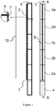
- the figure 1 schematically represents an injection ramp according to a first embodiment of the invention.
- the right part of the figure 1 represents a front view of an injection rail 1.
- a substrate 10 On the left side of the figure 1 , there is shown a substrate 10 on which it is desired to deposit a material and the injection rail 1 in longitudinal section along the direction AA '.
- an enlargement of a detail of the sectional view of the ramp In insert, on the left side of the figure 1 is shown an enlargement of a detail of the sectional view of the ramp.
- the injection rail extends along a longitudinal axis 5.
- the injection rail 1 comprises a reservoir module 4 for containing the material to be evaporated.
- the material to be evaporated can be in different forms (liquid, solid, powder ).
- the tank is intended to evaporate the following materials: silver (Ag), magnesium (Mg), gallium (Ga), indium (In), lithium fluoride (LiF), indium sulphide (In 2 S 3 ) zinc (Zn), cadmium (Cd), tin (Sn), aluminum (Al) or copper (Cu).
- the injection manifold 1 is mainly intended for be mounted vertically.
- the reservoir module 4 is positioned at the lower end of the ramp so as to contain the material not evaporated by gravity.
- the tank module is in line with the ramp.
- the reservoir module 4 may have a geometry, a disposition (in line, at 45 °, at 90 ° with respect to the longitudinal axis 5) or else a capacity (length, diameter) very particular according to the operation (horizontal or vertical), the material to be evaporated, the production time of the injection system or the consumption of material to be evaporated.
- the injection rail 1 also comprises a plurality of injection modules 2a, 2b, 2c, 2d, 2e connected in series.
- the example shown has five injection modules. However, the number of injection modules is of course not limited.
- the first injection module 2a is fixed on the reservoir module 4.
- the injection module 2b is fixed on an injection module 2a.
- the injection module 2c is fixed on an injection module 2b, etc.
- a shutter module 6 is fixed on the injection module 2e.
- the end of the ramp 1 opposite the reservoir module 4 is thus closed by the vapor-tight shutter module 6 of said material to be evaporated.
- the shutter module 6 can be integrated with an end injection module to form a single injection module closed at one end.
- the various injection modules comprising the ramp may be fixed to each other, for example by interlocking or by screwing.
- the injection modules are orientable about their axis so as to be able to make an angular adjustment of each injection module. This adjustment in orientation makes it possible to ensure the alignment of the nozzles along the ramp, this alignment being critical for the quality of the deposits.
- each injection module has a thread 7 adapted.
- the starting position of the thread is controlled with respect to the position of the nozzles, which gives a coarse alignment, the fine alignment is ensured by the compression of a seal.
- the reservoir module 4 and the injection modules 2a, 2b, 2c, 2d, 2e are tubular and hollow.
- the injection modules are cylindrical, the nozzles being aligned on a generatrix of the cylinder.
- the injection modules are of approximately circular section but include a flat which carries the nozzles.
- the injection module 2a communicates with the reservoir 4 through a central opening.
- the injection module 2b also communicates with the injection module 2a via a central opening and so on until the injection module 2e and the shutter module 6.
- the evaporated material leaving the reservoir can thus diffuse freely inside all the modules of the injection rail to the shutter module.
- the internal diameter of the various modules of the injection manifold is sufficient for its conductance to ensure a low or negligible pressure drop, thereby ensuring the same flow on each nozzle.
- Each injection module 2a, 2b, ... 2e is provided with a plurality of injection nozzles 3.
- a nozzle 3 generally comprises a channel connecting the interior of the ramp to the evaporation chamber to allow the diffusion of the material evaporated towards the substrate 10.
- the nozzles 3 of the different modules are aligned along an axis parallel to the axis 5 of the ramp.
- each injection module 2 comprises about twenty nozzles 3.
- the nozzles are distributed with a constant interval between consecutive nozzles so as to obtain a spatially uniform distribution of the nozzles 3 along the nozzle. an axis parallel to the axis 5.
- each nozzle is constituted by an insert, for example screwed on the injection module.
- a nozzle is interchangeable with a nozzle having a different opening. It is thus possible to arrange the nozzles 3 having different openings according to the position of the nozzle 3 along the ramp 1, in order to adjust the deposition profile over the entire surface of the substrate 10.
- the length of the nozzle an injection module 2a is equal to 400mm, the orientation accuracy by rotation about the longitudinal axis being less than two degrees, the space between nozzles is equal to 20mm, and the threading 7 extends over 10mm long.
- the injection modules, the shutter module and / or the reservoir module are made of a material which is chemically compatible with the material to be evaporated at the desired evaporation temperature.
- the material of the injection modules of the reservoir module and / or of a shutter module may be carbon, graphite, pyrolytic graphite, vitreous carbon, boron nitride, alumina, etc.
- sealing ring 8 made of flexible graphite of the order of 1 mm thick is interposed between two adjacent modules to seal and also to adjust the orientation of the different injection modules 2a, 2b. and thus allow to align the nozzles 3.
- the ramp 1 therefore consists of different modules connected in series to form a linear cell along the axis 5: reservoir module, injection modules and shutter module.
- the number of injection modules determines the length of the ramp and is easily reconfigurable.
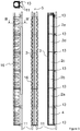
- the figure 2 represents a second embodiment of injection ramp, intended more particularly to be mounted horizontally along the axis 5.
- the right part of the figure 2 represents a bottom view of an injection manifold 1.
- a substrate 10 On the left side of the figure 2 there is shown a substrate 10 on which it is desired deposit a material and the injection rail 1 in longitudinal section along a section AA '.
- the same reference signs designate the same elements as on the figure 1 .
- the ramp of the figure 2 also comprises a reservoir module 4, several injection modules 2a, 2b, 2c, 2d, 2e connected in series and provided with injection nozzles 3, and a shutter module 6.
- the intermediate module is fixed on the one hand to the opening of the reservoir and on the other hand to the first injection module 2a.
- the intermediate module 9 has an inner wall which partially closes the inner opening of the ramp so as to contain the non-evaporated material in the tank.
- the inner wall has an opening for passing the flow of evaporated material (shown schematically by an arrow on the insert of the figure 2 ).
- This intermediate module 9 with internal wall is particularly suitable in the case where the reservoir module is aligned horizontally to allow to maintain the non-evaporated material in the reservoir module 4.
- the intermediate module is rotatable about the axis 5 of the ramp , so that the opening of the inner wall is in the upper part of the ramp, as shown in insert, in the case where the nozzles are oriented upwards.
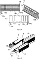
- the figure 3 represents different views of an injection rail provided with heating means to allow evaporation and diffusion of material.
- a ramp in front view to the left of the figure 3 in side view, to the right of the figure 3 a longitudinal sectional view along the axis 5 and at the top left of the figure 3 an axial sectional view of the ramp along the cutting plane BB '.
- the ramp includes the various modules as described in connection with the figure 1 , in particular a reservoir module 4, a plurality of injection modules 2a,..., 2e and an end module 6.
- the reservoir module 4 as well as each injection module is enveloped by a thermal shell.
- Each thermal shell has the same length as the reservoir module or injection module that it wraps.
- external cooling means of the thermal shells are observed in the form of coils 16 intended for the circulation of a cooling fluid, for example water.
- the injection rail is mounted on a frame comprising two cylindrical bars 11, the bars 11 being parallel to each other and parallel to the axis 5 of the ramp.
- the ramp 1 is fixed on the chassis by means of fixing lugs 13.
- the fixing lugs 13 are adjustable by sliding along the axis of the bars 11.
- a thermal shell is composed of two half-shells of generally semi-cylindrical shape and intended to envelop a ramp of external shape also cylindrical.
- the two half-shells forming a thermal shell are symmetrical with respect to a plane passing through the longitudinal axis 5 of the ramp.
- the figure 4 represents a front view, rear view and perspective view of a thermal half-shell for wrapping a module of an injection rail according to a particular embodiment.
- the half-shell 17 comprises on its inner face a filament 14 for heating a module of the ramp by radiation.
- the filament 14 makes it possible to carry the injection rail at a temperature that can reach 1200 ° C. to 1500 ° C.
- the half-shell 17 has electrical connections 14a, 14b at both ends of the filament 14.
- Each thermal half-shell can thus be connected to a source of electrical power independently of other thermal shells.
- Each thermal half-shell can also be connected in series with the other thermal shells to a single electric power source.
- the filament is protected from the environment of the ramp by a heat shield 15.
- a water cooling system 16 placed on the outer portion of the shell 17 reduces the outside temperature of the ramp.
- the cooling system 16 comprises fluidic connections 16a, 16b at both ends of the cooling circuit of a half-shell.
- Each thermal half-shell can thus be connected to a source of cooling water independently of the other thermal half-shells.
- Each thermal half-shell can also be connected in series with the other thermal half-shells to a single cooling water source.
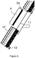
- FIG 5 schematically represents a perspective view of an injection rail during assembly / disassembly of a tank according to a particular embodiment.
- the two thermal half-shells 17 which surround the reservoir module are detached.
- the reservoir module is fitted or screwed by threads 7 on the first injection module 2a. This system makes it possible to leave the injection rail in place in the evaporation chamber.
- the tank change can be done very quickly.
- the figure 6 schematically represents a perspective view of an injection rail during assembly / disassembly of a tank according to another particular embodiment.
- the thermal shell surrounding the reservoir module is not dismantled, but simply moved by loosening the fastening tab 13 and then sliding the thermal shell along the bars 11 of the frame. The space released allows access to the tank to fill or replace it.
- it is sufficient to fix the reservoir module 4 on the first injection module 2a, then to slide the shell 17 along the bars 11 so that it envelops the reservoir module 4.
- the fixing lugs can be held by screws.
- the chassis provides the rigidity of the entire injection ramp 1.
- the chassis allows to interface the injection manifold with a transfer system to produce a movement of the ramp relative to substrates of large size. cut.
- the chassis makes it easy to orient one or more injection ramps relative to the plane of a substrate.
- the figure 7 illustrates different depot configurations.
- the use of a single injection rail for monoevaporation from a material tank has been illustrated.
- a system with two injection ramps 1 and 1 ' Each of the two injection ramps 1, 1 'has its own material tank. This system with two injection ramps easily allows the co-evaporation of different materials, which are deposited at the same time on the substrate.
- each ramp allows, by simple rotation around a bar, to orient each ramp, for example symmetrically with respect to the normal to the substrate.
- the two ramps advantageously have the same length, are parallel to each other, and parallel to the plane of the substrate which allows to obtain homogeneous co-evaporation over the entire length of the ramps 1 and 1 '.
- a system with three injection ramps 1, 1 ', 1 " is shown at the bottom of the figure 7 .
- Each of the three injection ramps 1, 1 ', 1 has its own reservoir of material, to allow the co-evaporation of three different materials, deposited simultaneously on the substrate 10.
- the three ramps have the same length, are disposed parallel to each other and parallel to the plane of the substrate 10, to allow uniform co-evaporation.
- injection rail by assembling different modules (injection modules, reservoir module) makes it possible to easily adapt to the size of the substrate to be treated and in particular to large substrate sizes.
- the manufacture of a ramp of particular length is based on the assembly of a predetermined number of injection modules, but does not require study or specific tools and is therefore of a lower cost.
- the reservoir module is easy to load and unload, which reduces the time when the device is stopped and thus improve the efficiency of the vacuum evaporation machine.
- the linear construction of the ramp injection allows to consider uniform co-evaporation configurations with two or three injection ramps or more.
Landscapes
- Chemical & Material Sciences (AREA)
- Chemical Kinetics & Catalysis (AREA)
- Engineering & Computer Science (AREA)
- Materials Engineering (AREA)
- Mechanical Engineering (AREA)
- Metallurgy (AREA)
- Organic Chemistry (AREA)
- Physical Vapour Deposition (AREA)
- Electroluminescent Light Sources (AREA)
Applications Claiming Priority (2)
| Application Number | Priority Date | Filing Date | Title |
|---|---|---|---|
| FR1159560A FR2981667B1 (fr) | 2011-10-21 | 2011-10-21 | Systeme d'injection pour dispositif de depot de couches minces par evaporation sous vide |
| PCT/FR2012/052388 WO2013057443A1 (fr) | 2011-10-21 | 2012-10-18 | Systeme d'injection pour dispositif de depot de couches minces par evaporation sous vide |
Publications (2)
| Publication Number | Publication Date |
|---|---|
| EP2769001A1 EP2769001A1 (fr) | 2014-08-27 |
| EP2769001B1 true EP2769001B1 (fr) | 2017-12-20 |
Family
ID=47221468
Family Applications (1)
| Application Number | Title | Priority Date | Filing Date |
|---|---|---|---|
| EP12790607.1A Active EP2769001B1 (fr) | 2011-10-21 | 2012-10-18 | Systeme d'injection pour dispositif de depot de couches minces par evaporation sous vide |
Country Status (9)
| Country | Link |
|---|---|
| US (1) | US20140245955A1 (enExample) |
| EP (1) | EP2769001B1 (enExample) |
| JP (1) | JP6170927B2 (enExample) |
| KR (1) | KR102108173B1 (enExample) |
| CN (1) | CN103906856B (enExample) |
| FR (1) | FR2981667B1 (enExample) |
| IN (1) | IN2014DN03425A (enExample) |
| SG (1) | SG11201401635PA (enExample) |
| WO (1) | WO2013057443A1 (enExample) |
Families Citing this family (12)
| Publication number | Priority date | Publication date | Assignee | Title |
|---|---|---|---|---|
| KR101990619B1 (ko) * | 2014-11-07 | 2019-06-18 | 어플라이드 머티어리얼스, 인코포레이티드 | 증발된 재료를 증착하기 위한 장치, 분배 파이프, 진공 증착 챔버, 및 증발된 재료를 증착하기 위한 방법 |
| US20170321318A1 (en) * | 2014-11-07 | 2017-11-09 | Applied Materials, Inc. | Material source arrangment and nozzle for vacuum deposition |
| JP6594986B2 (ja) * | 2014-11-07 | 2019-10-23 | アプライド マテリアルズ インコーポレイテッド | 真空堆積のための材料源アレンジメント及び材料分配アレンジメント |
| WO2017008838A1 (en) * | 2015-07-13 | 2017-01-19 | Applied Materials, Inc. | Evaporation source. |
| CN105088145B (zh) * | 2015-08-19 | 2017-03-29 | 京东方科技集团股份有限公司 | 用于oled蒸发源的坩埚及其制造方法 |
| CN205443432U (zh) * | 2016-04-07 | 2016-08-10 | 鄂尔多斯市源盛光电有限责任公司 | 一种线性蒸发源、蒸发源系统及蒸镀装置 |
| JP6823954B2 (ja) * | 2016-07-08 | 2021-02-03 | 株式会社ジャパンディスプレイ | 成膜装置および成膜方法 |
| CN106868456B (zh) * | 2017-03-21 | 2019-03-12 | 京东方科技集团股份有限公司 | 蒸发源和蒸镀设备 |
| JP6543664B2 (ja) * | 2017-09-11 | 2019-07-10 | アプライド マテリアルズ インコーポレイテッドApplied Materials,Incorporated | 真空堆積チャンバ |
| CN109943806A (zh) * | 2017-12-20 | 2019-06-28 | 合肥欣奕华智能机器有限公司 | 一种线性蒸发源装置及蒸镀装置 |
| CN109817842B (zh) * | 2019-01-16 | 2021-10-01 | 京东方科技集团股份有限公司 | 一种真空干燥装置、显示用基板的制备方法 |
| JP7842534B2 (ja) * | 2021-01-12 | 2026-04-08 | キヤノントッキ株式会社 | 蒸発源装置、成膜装置、成膜方法及び電子デバイスの製造方法 |
Citations (1)
| Publication number | Priority date | Publication date | Assignee | Title |
|---|---|---|---|---|
| US20060127599A1 (en) * | 2002-02-12 | 2006-06-15 | Wojak Gregory J | Process and apparatus for preparing a diamond substance |
Family Cites Families (26)
| Publication number | Priority date | Publication date | Assignee | Title |
|---|---|---|---|---|
| US2688500A (en) * | 1952-01-02 | 1954-09-07 | Laval Separator Co De | Coupling for pipes |
| US3661117A (en) * | 1969-12-03 | 1972-05-09 | Stanford Research Inst | Apparatus for depositing thin lines |
| US4016310A (en) * | 1975-04-23 | 1977-04-05 | Xerox Corporation | Coater hardware and method for obtaining uniform photoconductive layers on a xerographic photoreceptor |
| US4756465A (en) * | 1985-04-15 | 1988-07-12 | Latviisky Gosudarstvenny Institut | Method of cold welding |
| DE3636891A1 (de) * | 1986-10-30 | 1988-05-11 | Armin Dommer | Verfahren und vorrichtung zum stumpfschweissen von kunststoff-rohrabschnitten oder kunststoff-formstuecken |
| US5186120A (en) * | 1989-03-22 | 1993-02-16 | Mitsubishi Denki Kabushiki Kaisha | Mixture thin film forming apparatus |
| JP3139179B2 (ja) * | 1992-10-12 | 2001-02-26 | オイレス工業株式会社 | 球帯状シール体 |
| US5458725A (en) * | 1993-08-17 | 1995-10-17 | Motorola, Inc. | Gas distribution system |
| FR2800754B1 (fr) * | 1999-11-08 | 2003-05-09 | Joint Industrial Processors For Electronics | Dispositif evaporateur d'une installation de depot chimique en phase vapeur |
| DE10256038A1 (de) * | 2002-11-30 | 2004-06-17 | Applied Films Gmbh & Co. Kg | Bedampfungsvorrichtung |
| JP4015064B2 (ja) * | 2003-05-28 | 2007-11-28 | トッキ株式会社 | 蒸着装置 |
| KR100659762B1 (ko) * | 2005-01-17 | 2006-12-19 | 삼성에스디아이 주식회사 | 증발원, 증착장치 및 이를 이용한 증착방법 |
| KR101153161B1 (ko) * | 2005-04-01 | 2012-06-18 | 주성엔지니어링(주) | 가스분사장치 및 이를 포함하는 액정표시소자의 제조장치 |
| EP1752555A1 (de) * | 2005-07-28 | 2007-02-14 | Applied Materials GmbH & Co. KG | Verdampfervorrichtung |
| JP5213341B2 (ja) * | 2007-03-20 | 2013-06-19 | 東京エレクトロン株式会社 | 気化器,気化モジュール,成膜装置 |
| JP2008274322A (ja) * | 2007-04-26 | 2008-11-13 | Sony Corp | 蒸着装置 |
| JP5043776B2 (ja) * | 2008-08-08 | 2012-10-10 | 株式会社日立国際電気 | 基板処理装置及び半導体装置の製造方法 |
| US8512806B2 (en) * | 2008-08-12 | 2013-08-20 | Momentive Performance Materials Inc. | Large volume evaporation source |
| US20100159132A1 (en) * | 2008-12-18 | 2010-06-24 | Veeco Instruments, Inc. | Linear Deposition Source |
| JP4831841B2 (ja) * | 2009-07-10 | 2011-12-07 | 三菱重工業株式会社 | 真空蒸着装置及び方法 |
| KR100977374B1 (ko) * | 2009-08-03 | 2010-08-20 | 텔리오솔라 테크놀로지스 인크 | 대면적 박막형 cigs 태양전지 고속증착 및 양산장비, 그 공정방법 |
| JP5642952B2 (ja) * | 2009-09-07 | 2014-12-17 | 花王株式会社 | 包装箱 |
| DE102010046389A1 (de) * | 2009-09-25 | 2011-05-19 | Creaphys Gmbh | Verdampfereinrichtung für eine Beschichtungsanlage und Beschichtungsanlage |
| WO2011082179A1 (en) * | 2009-12-28 | 2011-07-07 | Global Solar Energy, Inc. | Apparatus and methods of mixing and depositing thin film photovoltaic compositions |
| FR2956412B1 (fr) * | 2010-02-16 | 2012-04-06 | Astron Fiamm Safety | Vanne d'obturation a volume constant d'une source de depot en phase vapeur |
| CN103430625B (zh) * | 2011-03-15 | 2015-09-23 | 夏普株式会社 | 蒸镀装置、蒸镀方法和有机el显示装置的制造方法 |
-
2011
- 2011-10-21 FR FR1159560A patent/FR2981667B1/fr active Active
-
2012
- 2012-10-18 EP EP12790607.1A patent/EP2769001B1/fr active Active
- 2012-10-18 WO PCT/FR2012/052388 patent/WO2013057443A1/fr not_active Ceased
- 2012-10-18 CN CN201280051570.2A patent/CN103906856B/zh active Active
- 2012-10-18 JP JP2014536318A patent/JP6170927B2/ja active Active
- 2012-10-18 US US14/350,104 patent/US20140245955A1/en not_active Abandoned
- 2012-10-18 IN IN3425DEN2014 patent/IN2014DN03425A/en unknown
- 2012-10-18 KR KR1020147010540A patent/KR102108173B1/ko active Active
- 2012-10-18 SG SG11201401635PA patent/SG11201401635PA/en unknown
Patent Citations (1)
| Publication number | Priority date | Publication date | Assignee | Title |
|---|---|---|---|---|
| US20060127599A1 (en) * | 2002-02-12 | 2006-06-15 | Wojak Gregory J | Process and apparatus for preparing a diamond substance |
Also Published As
| Publication number | Publication date |
|---|---|
| US20140245955A1 (en) | 2014-09-04 |
| FR2981667A1 (fr) | 2013-04-26 |
| EP2769001A1 (fr) | 2014-08-27 |
| IN2014DN03425A (enExample) | 2015-06-05 |
| FR2981667B1 (fr) | 2014-07-04 |
| CN103906856A (zh) | 2014-07-02 |
| KR102108173B1 (ko) | 2020-05-08 |
| JP6170927B2 (ja) | 2017-07-26 |
| CN103906856B (zh) | 2016-11-09 |
| WO2013057443A1 (fr) | 2013-04-25 |
| SG11201401635PA (en) | 2014-09-26 |
| KR20140092816A (ko) | 2014-07-24 |
| JP2015501379A (ja) | 2015-01-15 |
Similar Documents
| Publication | Publication Date | Title |
|---|---|---|
| EP2769001B1 (fr) | Systeme d'injection pour dispositif de depot de couches minces par evaporation sous vide | |
| CA2655711C (fr) | Appareil de broyage d'echantillons biologiques | |
| CH626456A5 (enExample) | ||
| US20130337174A1 (en) | Vaporization source, vaporization chamber, coating method and nozzle plate | |
| EP2937443A1 (fr) | Cellule d'évaporation | |
| EP3973581B1 (fr) | Batterie équipée d'un dispositif de régulation de température à l'aide d'un fluide diélectrique | |
| EP2577678B1 (fr) | Emballage pour le transport et/ou entreposage de matieres radioactives, comprenant des moyens de conduction thermique ameliores | |
| FR3018082A1 (fr) | Procede de rechargement d'une cellule d'evaporation | |
| FR2879218A1 (fr) | Dispositif pour vaporiser un materiau et appliquer un materiau vaporise sur une structure | |
| EP2320429A1 (fr) | Emballage pour le transport et/ou entreposage de matières radioactives comprenant des éléments de protection radiologique empiles radialement | |
| EP1330402A1 (fr) | Dispositif de transfert de materiaux pulverulents, et application a l'alimentation d'un metal en fusion en materiau pulverulent | |
| EP2103565B1 (fr) | Appareil de distribution de boisson muni d'un élément caloporteur | |
| EP3504057B1 (fr) | Outil de pressage a chaud, son procede de mise en oeuvre, installation et procede de fabrication correspondants | |
| EP3084934A2 (fr) | Méthode de refroidissement d'une génératrice électrique et dispositif pour la mise en oeuvre de cette méthode | |
| FR2597260A1 (fr) | Procede d'introduction directe automatique d'echantillons dans un spectrometre de masse, et dispositif pour la mise en oeuvre de ce procede | |
| EP3880556A1 (fr) | Procédé de fixation d'un équipement dissipatif, mur de véhicule spatial et véhicule spatial | |
| FR2956412A1 (fr) | Vanne d'obturation a volume constant d'une source de depot en phase vapeur | |
| EP0148695A2 (fr) | Chauffe-eau solaire pour le chauffage et le stockage par passage direct de l'eau et son procédé de fabrication | |
| BE1020306A3 (fr) | Systeme magnetron avec une cible creuse. | |
| EP0241447A1 (fr) | Cathode de pulvérisation | |
| FR3149432A1 (fr) | Dispositif contrôlé thermiquement de stockage d'énergie électrique et véhicule associé | |
| EP2861928A1 (fr) | Dispositif de contrôle thermique | |
| WO2007063259A1 (fr) | Cellule d'effusion haute temperature de grande capacite | |
| FR3059341A1 (fr) | Electrode pour installation de traitement de surface d'un substrat en mouvement, unite et installation correspondantes | |
| EP0792382A1 (fr) | Appareil de depot sous vide relatif d'un materiau sur des pieces en vrac |
Legal Events
| Date | Code | Title | Description |
|---|---|---|---|
| PUAI | Public reference made under article 153(3) epc to a published international application that has entered the european phase |
Free format text: ORIGINAL CODE: 0009012 |
|
| 17P | Request for examination filed |
Effective date: 20140408 |
|
| AK | Designated contracting states |
Kind code of ref document: A1 Designated state(s): AL AT BE BG CH CY CZ DE DK EE ES FI FR GB GR HR HU IE IS IT LI LT LU LV MC MK MT NL NO PL PT RO RS SE SI SK SM TR |
|
| DAX | Request for extension of the european patent (deleted) | ||
| STAA | Information on the status of an ep patent application or granted ep patent |
Free format text: STATUS: EXAMINATION IS IN PROGRESS |
|
| 17Q | First examination report despatched |
Effective date: 20170103 |
|
| GRAP | Despatch of communication of intention to grant a patent |
Free format text: ORIGINAL CODE: EPIDOSNIGR1 |
|
| STAA | Information on the status of an ep patent application or granted ep patent |
Free format text: STATUS: GRANT OF PATENT IS INTENDED |
|
| INTG | Intention to grant announced |
Effective date: 20170706 |
|
| RIN1 | Information on inventor provided before grant (corrected) |
Inventor name: BRIANT, NICOLAS Inventor name: ESTEVE, DAVID Inventor name: VILLETTE, JEROME Inventor name: GUYAUX, JEAN-LOUIS |
|
| GRAS | Grant fee paid |
Free format text: ORIGINAL CODE: EPIDOSNIGR3 |
|
| GRAA | (expected) grant |
Free format text: ORIGINAL CODE: 0009210 |
|
| STAA | Information on the status of an ep patent application or granted ep patent |
Free format text: STATUS: THE PATENT HAS BEEN GRANTED |
|
| AK | Designated contracting states |
Kind code of ref document: B1 Designated state(s): AL AT BE BG CH CY CZ DE DK EE ES FI FR GB GR HR HU IE IS IT LI LT LU LV MC MK MT NL NO PL PT RO RS SE SI SK SM TR |
|
| REG | Reference to a national code |
Ref country code: GB Ref legal event code: FG4D Free format text: NOT ENGLISH |
|
| REG | Reference to a national code |
Ref country code: CH Ref legal event code: EP |
|
| REG | Reference to a national code |
Ref country code: IE Ref legal event code: FG4D Free format text: LANGUAGE OF EP DOCUMENT: FRENCH |
|
| REG | Reference to a national code |
Ref country code: AT Ref legal event code: REF Ref document number: 956462 Country of ref document: AT Kind code of ref document: T Effective date: 20180115 |
|
| REG | Reference to a national code |
Ref country code: DE Ref legal event code: R096 Ref document number: 602012041159 Country of ref document: DE |
|
| REG | Reference to a national code |
Ref country code: NL Ref legal event code: MP Effective date: 20171220 |
|
| PG25 | Lapsed in a contracting state [announced via postgrant information from national office to epo] |
Ref country code: LT Free format text: LAPSE BECAUSE OF FAILURE TO SUBMIT A TRANSLATION OF THE DESCRIPTION OR TO PAY THE FEE WITHIN THE PRESCRIBED TIME-LIMIT Effective date: 20171220 Ref country code: SE Free format text: LAPSE BECAUSE OF FAILURE TO SUBMIT A TRANSLATION OF THE DESCRIPTION OR TO PAY THE FEE WITHIN THE PRESCRIBED TIME-LIMIT Effective date: 20171220 Ref country code: NO Free format text: LAPSE BECAUSE OF FAILURE TO SUBMIT A TRANSLATION OF THE DESCRIPTION OR TO PAY THE FEE WITHIN THE PRESCRIBED TIME-LIMIT Effective date: 20180320 Ref country code: FI Free format text: LAPSE BECAUSE OF FAILURE TO SUBMIT A TRANSLATION OF THE DESCRIPTION OR TO PAY THE FEE WITHIN THE PRESCRIBED TIME-LIMIT Effective date: 20171220 |
|
| REG | Reference to a national code |
Ref country code: LT Ref legal event code: MG4D |
|
| REG | Reference to a national code |
Ref country code: AT Ref legal event code: MK05 Ref document number: 956462 Country of ref document: AT Kind code of ref document: T Effective date: 20171220 |
|
| PG25 | Lapsed in a contracting state [announced via postgrant information from national office to epo] |
Ref country code: BG Free format text: LAPSE BECAUSE OF FAILURE TO SUBMIT A TRANSLATION OF THE DESCRIPTION OR TO PAY THE FEE WITHIN THE PRESCRIBED TIME-LIMIT Effective date: 20180320 Ref country code: GR Free format text: LAPSE BECAUSE OF FAILURE TO SUBMIT A TRANSLATION OF THE DESCRIPTION OR TO PAY THE FEE WITHIN THE PRESCRIBED TIME-LIMIT Effective date: 20180321 Ref country code: RS Free format text: LAPSE BECAUSE OF FAILURE TO SUBMIT A TRANSLATION OF THE DESCRIPTION OR TO PAY THE FEE WITHIN THE PRESCRIBED TIME-LIMIT Effective date: 20171220 Ref country code: HR Free format text: LAPSE BECAUSE OF FAILURE TO SUBMIT A TRANSLATION OF THE DESCRIPTION OR TO PAY THE FEE WITHIN THE PRESCRIBED TIME-LIMIT Effective date: 20171220 Ref country code: LV Free format text: LAPSE BECAUSE OF FAILURE TO SUBMIT A TRANSLATION OF THE DESCRIPTION OR TO PAY THE FEE WITHIN THE PRESCRIBED TIME-LIMIT Effective date: 20171220 |
|
| PG25 | Lapsed in a contracting state [announced via postgrant information from national office to epo] |
Ref country code: NL Free format text: LAPSE BECAUSE OF FAILURE TO SUBMIT A TRANSLATION OF THE DESCRIPTION OR TO PAY THE FEE WITHIN THE PRESCRIBED TIME-LIMIT Effective date: 20171220 |
|
| PG25 | Lapsed in a contracting state [announced via postgrant information from national office to epo] |
Ref country code: SK Free format text: LAPSE BECAUSE OF FAILURE TO SUBMIT A TRANSLATION OF THE DESCRIPTION OR TO PAY THE FEE WITHIN THE PRESCRIBED TIME-LIMIT Effective date: 20171220 Ref country code: CZ Free format text: LAPSE BECAUSE OF FAILURE TO SUBMIT A TRANSLATION OF THE DESCRIPTION OR TO PAY THE FEE WITHIN THE PRESCRIBED TIME-LIMIT Effective date: 20171220 Ref country code: EE Free format text: LAPSE BECAUSE OF FAILURE TO SUBMIT A TRANSLATION OF THE DESCRIPTION OR TO PAY THE FEE WITHIN THE PRESCRIBED TIME-LIMIT Effective date: 20171220 Ref country code: CY Free format text: LAPSE BECAUSE OF FAILURE TO SUBMIT A TRANSLATION OF THE DESCRIPTION OR TO PAY THE FEE WITHIN THE PRESCRIBED TIME-LIMIT Effective date: 20171220 Ref country code: ES Free format text: LAPSE BECAUSE OF FAILURE TO SUBMIT A TRANSLATION OF THE DESCRIPTION OR TO PAY THE FEE WITHIN THE PRESCRIBED TIME-LIMIT Effective date: 20171220 |
|
| PG25 | Lapsed in a contracting state [announced via postgrant information from national office to epo] |
Ref country code: IT Free format text: LAPSE BECAUSE OF FAILURE TO SUBMIT A TRANSLATION OF THE DESCRIPTION OR TO PAY THE FEE WITHIN THE PRESCRIBED TIME-LIMIT Effective date: 20171220 Ref country code: RO Free format text: LAPSE BECAUSE OF FAILURE TO SUBMIT A TRANSLATION OF THE DESCRIPTION OR TO PAY THE FEE WITHIN THE PRESCRIBED TIME-LIMIT Effective date: 20171220 Ref country code: IS Free format text: LAPSE BECAUSE OF FAILURE TO SUBMIT A TRANSLATION OF THE DESCRIPTION OR TO PAY THE FEE WITHIN THE PRESCRIBED TIME-LIMIT Effective date: 20180420 Ref country code: AT Free format text: LAPSE BECAUSE OF FAILURE TO SUBMIT A TRANSLATION OF THE DESCRIPTION OR TO PAY THE FEE WITHIN THE PRESCRIBED TIME-LIMIT Effective date: 20171220 Ref country code: SM Free format text: LAPSE BECAUSE OF FAILURE TO SUBMIT A TRANSLATION OF THE DESCRIPTION OR TO PAY THE FEE WITHIN THE PRESCRIBED TIME-LIMIT Effective date: 20171220 Ref country code: PL Free format text: LAPSE BECAUSE OF FAILURE TO SUBMIT A TRANSLATION OF THE DESCRIPTION OR TO PAY THE FEE WITHIN THE PRESCRIBED TIME-LIMIT Effective date: 20171220 |
|
| REG | Reference to a national code |
Ref country code: FR Ref legal event code: PLFP Year of fee payment: 7 |
|
| REG | Reference to a national code |
Ref country code: DE Ref legal event code: R097 Ref document number: 602012041159 Country of ref document: DE |
|
| PG25 | Lapsed in a contracting state [announced via postgrant information from national office to epo] |
Ref country code: MT Free format text: LAPSE BECAUSE OF FAILURE TO SUBMIT A TRANSLATION OF THE DESCRIPTION OR TO PAY THE FEE WITHIN THE PRESCRIBED TIME-LIMIT Effective date: 20171220 |
|
| PLBE | No opposition filed within time limit |
Free format text: ORIGINAL CODE: 0009261 |
|
| STAA | Information on the status of an ep patent application or granted ep patent |
Free format text: STATUS: NO OPPOSITION FILED WITHIN TIME LIMIT |
|
| 26N | No opposition filed |
Effective date: 20180921 |
|
| PG25 | Lapsed in a contracting state [announced via postgrant information from national office to epo] |
Ref country code: DK Free format text: LAPSE BECAUSE OF FAILURE TO SUBMIT A TRANSLATION OF THE DESCRIPTION OR TO PAY THE FEE WITHIN THE PRESCRIBED TIME-LIMIT Effective date: 20171220 |
|
| PG25 | Lapsed in a contracting state [announced via postgrant information from national office to epo] |
Ref country code: SI Free format text: LAPSE BECAUSE OF FAILURE TO SUBMIT A TRANSLATION OF THE DESCRIPTION OR TO PAY THE FEE WITHIN THE PRESCRIBED TIME-LIMIT Effective date: 20171220 |
|
| REG | Reference to a national code |
Ref country code: CH Ref legal event code: PL |
|
| GBPC | Gb: european patent ceased through non-payment of renewal fee |
Effective date: 20181018 |
|
| REG | Reference to a national code |
Ref country code: BE Ref legal event code: MM Effective date: 20181031 |
|
| PG25 | Lapsed in a contracting state [announced via postgrant information from national office to epo] |
Ref country code: MC Free format text: LAPSE BECAUSE OF FAILURE TO SUBMIT A TRANSLATION OF THE DESCRIPTION OR TO PAY THE FEE WITHIN THE PRESCRIBED TIME-LIMIT Effective date: 20171220 Ref country code: LU Free format text: LAPSE BECAUSE OF NON-PAYMENT OF DUE FEES Effective date: 20181018 |
|
| REG | Reference to a national code |
Ref country code: IE Ref legal event code: MM4A |
|
| PG25 | Lapsed in a contracting state [announced via postgrant information from national office to epo] |
Ref country code: BE Free format text: LAPSE BECAUSE OF NON-PAYMENT OF DUE FEES Effective date: 20181031 Ref country code: LI Free format text: LAPSE BECAUSE OF NON-PAYMENT OF DUE FEES Effective date: 20181031 Ref country code: CH Free format text: LAPSE BECAUSE OF NON-PAYMENT OF DUE FEES Effective date: 20181031 |
|
| PG25 | Lapsed in a contracting state [announced via postgrant information from national office to epo] |
Ref country code: IE Free format text: LAPSE BECAUSE OF NON-PAYMENT OF DUE FEES Effective date: 20181018 Ref country code: GB Free format text: LAPSE BECAUSE OF NON-PAYMENT OF DUE FEES Effective date: 20181018 |
|
| PG25 | Lapsed in a contracting state [announced via postgrant information from national office to epo] |
Ref country code: TR Free format text: LAPSE BECAUSE OF FAILURE TO SUBMIT A TRANSLATION OF THE DESCRIPTION OR TO PAY THE FEE WITHIN THE PRESCRIBED TIME-LIMIT Effective date: 20171220 |
|
| PG25 | Lapsed in a contracting state [announced via postgrant information from national office to epo] |
Ref country code: PT Free format text: LAPSE BECAUSE OF FAILURE TO SUBMIT A TRANSLATION OF THE DESCRIPTION OR TO PAY THE FEE WITHIN THE PRESCRIBED TIME-LIMIT Effective date: 20171220 |
|
| PG25 | Lapsed in a contracting state [announced via postgrant information from national office to epo] |
Ref country code: HU Free format text: LAPSE BECAUSE OF FAILURE TO SUBMIT A TRANSLATION OF THE DESCRIPTION OR TO PAY THE FEE WITHIN THE PRESCRIBED TIME-LIMIT; INVALID AB INITIO Effective date: 20121018 Ref country code: MK Free format text: LAPSE BECAUSE OF NON-PAYMENT OF DUE FEES Effective date: 20171220 |
|
| PG25 | Lapsed in a contracting state [announced via postgrant information from national office to epo] |
Ref country code: AL Free format text: LAPSE BECAUSE OF FAILURE TO SUBMIT A TRANSLATION OF THE DESCRIPTION OR TO PAY THE FEE WITHIN THE PRESCRIBED TIME-LIMIT Effective date: 20171220 |
|
| PGFP | Annual fee paid to national office [announced via postgrant information from national office to epo] |
Ref country code: FR Payment date: 20250901 Year of fee payment: 14 |
|
| PGFP | Annual fee paid to national office [announced via postgrant information from national office to epo] |
Ref country code: DE Payment date: 20250904 Year of fee payment: 14 |