EP2767570A2 - Reaktionsmaterial und chemische Wärmepumpe - Google Patents
Reaktionsmaterial und chemische Wärmepumpe Download PDFInfo
- Publication number
- EP2767570A2 EP2767570A2 EP14155172.1A EP14155172A EP2767570A2 EP 2767570 A2 EP2767570 A2 EP 2767570A2 EP 14155172 A EP14155172 A EP 14155172A EP 2767570 A2 EP2767570 A2 EP 2767570A2
- Authority
- EP
- European Patent Office
- Prior art keywords
- magnesium
- reaction material
- heat pump
- reaction
- chemical heat
- Prior art date
- Legal status (The legal status is an assumption and is not a legal conclusion. Google has not performed a legal analysis and makes no representation as to the accuracy of the status listed.)
- Granted
Links
- 238000006243 chemical reaction Methods 0.000 title claims abstract description 232
- 239000000463 material Substances 0.000 title claims abstract description 217
- 239000000126 substance Substances 0.000 title claims abstract description 59
- OSGAYBCDTDRGGQ-UHFFFAOYSA-L calcium sulfate Chemical compound [Ca+2].[O-]S([O-])(=O)=O OSGAYBCDTDRGGQ-UHFFFAOYSA-L 0.000 claims abstract description 220
- 239000011777 magnesium Substances 0.000 claims abstract description 111
- 238000000034 method Methods 0.000 claims abstract description 106
- 230000008569 process Effects 0.000 claims abstract description 103
- 150000002681 magnesium compounds Chemical class 0.000 claims abstract description 67
- 238000005338 heat storage Methods 0.000 claims abstract description 32
- ZOMBKNNSYQHRCA-UHFFFAOYSA-J calcium sulfate hemihydrate Chemical compound O.[Ca+2].[Ca+2].[O-]S([O-])(=O)=O.[O-]S([O-])(=O)=O ZOMBKNNSYQHRCA-UHFFFAOYSA-J 0.000 claims abstract description 24
- -1 hemihydrate gypsum Chemical class 0.000 claims abstract description 17
- 150000001875 compounds Chemical class 0.000 claims abstract description 13
- XLYOFNOQVPJJNP-UHFFFAOYSA-N water Substances O XLYOFNOQVPJJNP-UHFFFAOYSA-N 0.000 claims description 77
- 239000011575 calcium Substances 0.000 claims description 68
- KRKNYBCHXYNGOX-UHFFFAOYSA-N citric acid Chemical compound OC(=O)CC(O)(C(O)=O)CC(O)=O KRKNYBCHXYNGOX-UHFFFAOYSA-N 0.000 claims description 49
- 239000000203 mixture Substances 0.000 claims description 43
- FYYHWMGAXLPEAU-UHFFFAOYSA-N Magnesium Chemical group [Mg] FYYHWMGAXLPEAU-UHFFFAOYSA-N 0.000 claims description 31
- 229910052749 magnesium Inorganic materials 0.000 claims description 31
- CSNNHWWHGAXBCP-UHFFFAOYSA-L Magnesium sulfate Chemical compound [Mg+2].[O-][S+2]([O-])([O-])[O-] CSNNHWWHGAXBCP-UHFFFAOYSA-L 0.000 claims description 30
- 239000013078 crystal Substances 0.000 claims description 23
- YIXJRHPUWRPCBB-UHFFFAOYSA-N magnesium nitrate Chemical compound [Mg+2].[O-][N+]([O-])=O.[O-][N+]([O-])=O YIXJRHPUWRPCBB-UHFFFAOYSA-N 0.000 claims description 20
- 238000002156 mixing Methods 0.000 claims description 16
- 229910052943 magnesium sulfate Inorganic materials 0.000 claims description 15
- 235000019341 magnesium sulphate Nutrition 0.000 claims description 15
- 238000004898 kneading Methods 0.000 claims description 14
- VTHJTEIRLNZDEV-UHFFFAOYSA-L magnesium dihydroxide Chemical compound [OH-].[OH-].[Mg+2] VTHJTEIRLNZDEV-UHFFFAOYSA-L 0.000 claims description 13
- 239000000347 magnesium hydroxide Substances 0.000 claims description 13
- 229910001862 magnesium hydroxide Inorganic materials 0.000 claims description 13
- OYPRJOBELJOOCE-UHFFFAOYSA-N Calcium Chemical compound [Ca] OYPRJOBELJOOCE-UHFFFAOYSA-N 0.000 claims description 11
- 229910052791 calcium Inorganic materials 0.000 claims description 11
- UEGPKNKPLBYCNK-UHFFFAOYSA-L magnesium acetate Chemical compound [Mg+2].CC([O-])=O.CC([O-])=O UEGPKNKPLBYCNK-UHFFFAOYSA-L 0.000 claims description 10
- 229940069446 magnesium acetate Drugs 0.000 claims description 10
- 239000011654 magnesium acetate Substances 0.000 claims description 10
- 235000011285 magnesium acetate Nutrition 0.000 claims description 10
- PJJZFXPJNUVBMR-UHFFFAOYSA-L magnesium benzoate Chemical compound [Mg+2].[O-]C(=O)C1=CC=CC=C1.[O-]C(=O)C1=CC=CC=C1 PJJZFXPJNUVBMR-UHFFFAOYSA-L 0.000 claims description 10
- TWRXJAOTZQYOKJ-UHFFFAOYSA-L Magnesium chloride Chemical compound [Mg+2].[Cl-].[Cl-] TWRXJAOTZQYOKJ-UHFFFAOYSA-L 0.000 claims description 8
- 238000010304 firing Methods 0.000 claims description 7
- OTCKOJUMXQWKQG-UHFFFAOYSA-L magnesium bromide Chemical compound [Mg+2].[Br-].[Br-] OTCKOJUMXQWKQG-UHFFFAOYSA-L 0.000 claims description 4
- 229910001623 magnesium bromide Inorganic materials 0.000 claims description 4
- 229910001629 magnesium chloride Inorganic materials 0.000 claims description 4
- BLQJIBCZHWBKSL-UHFFFAOYSA-L magnesium iodide Chemical compound [Mg+2].[I-].[I-] BLQJIBCZHWBKSL-UHFFFAOYSA-L 0.000 claims description 4
- 229910001641 magnesium iodide Inorganic materials 0.000 claims description 4
- 230000007246 mechanism Effects 0.000 claims description 3
- 230000000052 comparative effect Effects 0.000 description 45
- 230000008859 change Effects 0.000 description 39
- 238000006731 degradation reaction Methods 0.000 description 34
- 230000015556 catabolic process Effects 0.000 description 31
- 239000007864 aqueous solution Substances 0.000 description 30
- 238000002441 X-ray diffraction Methods 0.000 description 21
- 229910052602 gypsum Inorganic materials 0.000 description 21
- 239000012153 distilled water Substances 0.000 description 20
- 239000012429 reaction media Substances 0.000 description 16
- 150000008064 anhydrides Chemical class 0.000 description 15
- 230000007423 decrease Effects 0.000 description 13
- 238000006297 dehydration reaction Methods 0.000 description 12
- 230000018044 dehydration Effects 0.000 description 11
- 239000010440 gypsum Substances 0.000 description 11
- 238000006703 hydration reaction Methods 0.000 description 10
- 230000020169 heat generation Effects 0.000 description 9
- 230000036571 hydration Effects 0.000 description 9
- 238000004519 manufacturing process Methods 0.000 description 9
- 239000007788 liquid Substances 0.000 description 8
- 238000000465 moulding Methods 0.000 description 8
- 238000002360 preparation method Methods 0.000 description 8
- 230000001629 suppression Effects 0.000 description 7
- MFUVDXOKPBAHMC-UHFFFAOYSA-N magnesium;dinitrate;hexahydrate Chemical compound O.O.O.O.O.O.[Mg+2].[O-][N+]([O-])=O.[O-][N+]([O-])=O MFUVDXOKPBAHMC-UHFFFAOYSA-N 0.000 description 6
- 238000001704 evaporation Methods 0.000 description 5
- 230000002441 reversible effect Effects 0.000 description 5
- 238000001035 drying Methods 0.000 description 4
- WRUGWIBCXHJTDG-UHFFFAOYSA-L magnesium sulfate heptahydrate Chemical compound O.O.O.O.O.O.O.[Mg+2].[O-]S([O-])(=O)=O WRUGWIBCXHJTDG-UHFFFAOYSA-L 0.000 description 4
- 229940061634 magnesium sulfate heptahydrate Drugs 0.000 description 4
- 238000010521 absorption reaction Methods 0.000 description 3
- 239000001354 calcium citrate Substances 0.000 description 3
- 229940097364 magnesium acetate tetrahydrate Drugs 0.000 description 3
- 239000000395 magnesium oxide Substances 0.000 description 3
- CPLXHLVBOLITMK-UHFFFAOYSA-N magnesium oxide Inorganic materials [Mg]=O CPLXHLVBOLITMK-UHFFFAOYSA-N 0.000 description 3
- XKPKPGCRSHFTKM-UHFFFAOYSA-L magnesium;diacetate;tetrahydrate Chemical compound O.O.O.O.[Mg+2].CC([O-])=O.CC([O-])=O XKPKPGCRSHFTKM-UHFFFAOYSA-L 0.000 description 3
- LORPPIYFNZTKOE-UHFFFAOYSA-L magnesium;dibenzoate;trihydrate Chemical compound O.O.O.[Mg+2].[O-]C(=O)C1=CC=CC=C1.[O-]C(=O)C1=CC=CC=C1 LORPPIYFNZTKOE-UHFFFAOYSA-L 0.000 description 3
- AXZKOIWUVFPNLO-UHFFFAOYSA-N magnesium;oxygen(2-) Chemical compound [O-2].[Mg+2] AXZKOIWUVFPNLO-UHFFFAOYSA-N 0.000 description 3
- 235000013337 tricalcium citrate Nutrition 0.000 description 3
- ODINCKMPIJJUCX-UHFFFAOYSA-N Calcium oxide Chemical compound [Ca]=O ODINCKMPIJJUCX-UHFFFAOYSA-N 0.000 description 2
- 239000000654 additive Substances 0.000 description 2
- 230000000996 additive effect Effects 0.000 description 2
- 229910052925 anhydrite Inorganic materials 0.000 description 2
- FNAQSUUGMSOBHW-UHFFFAOYSA-H calcium citrate Chemical compound [Ca+2].[Ca+2].[Ca+2].[O-]C(=O)CC(O)(CC([O-])=O)C([O-])=O.[O-]C(=O)CC(O)(CC([O-])=O)C([O-])=O FNAQSUUGMSOBHW-UHFFFAOYSA-H 0.000 description 2
- 230000003247 decreasing effect Effects 0.000 description 2
- 238000003795 desorption Methods 0.000 description 2
- 230000008020 evaporation Effects 0.000 description 2
- 238000010438 heat treatment Methods 0.000 description 2
- 239000002245 particle Substances 0.000 description 2
- 239000000843 powder Substances 0.000 description 2
- 230000002123 temporal effect Effects 0.000 description 2
- 230000009471 action Effects 0.000 description 1
- BRPQOXSCLDDYGP-UHFFFAOYSA-N calcium oxide Chemical compound [O-2].[Ca+2] BRPQOXSCLDDYGP-UHFFFAOYSA-N 0.000 description 1
- 239000000292 calcium oxide Substances 0.000 description 1
- 239000010432 diamond Substances 0.000 description 1
- 238000004134 energy conservation Methods 0.000 description 1
- 238000005259 measurement Methods 0.000 description 1
- 239000002994 raw material Substances 0.000 description 1
- 238000011084 recovery Methods 0.000 description 1
- 238000003860 storage Methods 0.000 description 1
- 239000011232 storage material Substances 0.000 description 1
- 229910021653 sulphate ion Inorganic materials 0.000 description 1
- 230000007704 transition Effects 0.000 description 1
Images


Classifications
-
- C—CHEMISTRY; METALLURGY
- C09—DYES; PAINTS; POLISHES; NATURAL RESINS; ADHESIVES; COMPOSITIONS NOT OTHERWISE PROVIDED FOR; APPLICATIONS OF MATERIALS NOT OTHERWISE PROVIDED FOR
- C09K—MATERIALS FOR MISCELLANEOUS APPLICATIONS, NOT PROVIDED FOR ELSEWHERE
- C09K5/00—Heat-transfer, heat-exchange or heat-storage materials, e.g. refrigerants; Materials for the production of heat or cold by chemical reactions other than by combustion
- C09K5/16—Materials undergoing chemical reactions when used
-
- F—MECHANICAL ENGINEERING; LIGHTING; HEATING; WEAPONS; BLASTING
- F25—REFRIGERATION OR COOLING; COMBINED HEATING AND REFRIGERATION SYSTEMS; HEAT PUMP SYSTEMS; MANUFACTURE OR STORAGE OF ICE; LIQUEFACTION SOLIDIFICATION OF GASES
- F25B—REFRIGERATION MACHINES, PLANTS OR SYSTEMS; COMBINED HEATING AND REFRIGERATION SYSTEMS; HEAT PUMP SYSTEMS
- F25B17/00—Sorption machines, plants or systems, operating intermittently, e.g. absorption or adsorption type
- F25B17/08—Sorption machines, plants or systems, operating intermittently, e.g. absorption or adsorption type the absorbent or adsorbent being a solid, e.g. salt
-
- F—MECHANICAL ENGINEERING; LIGHTING; HEATING; WEAPONS; BLASTING
- F28—HEAT EXCHANGE IN GENERAL
- F28D—HEAT-EXCHANGE APPARATUS, NOT PROVIDED FOR IN ANOTHER SUBCLASS, IN WHICH THE HEAT-EXCHANGE MEDIA DO NOT COME INTO DIRECT CONTACT
- F28D20/00—Heat storage plants or apparatus in general; Regenerative heat-exchange apparatus not covered by groups F28D17/00 or F28D19/00
- F28D20/003—Heat storage plants or apparatus in general; Regenerative heat-exchange apparatus not covered by groups F28D17/00 or F28D19/00 using thermochemical reactions
-
- F—MECHANICAL ENGINEERING; LIGHTING; HEATING; WEAPONS; BLASTING
- F28—HEAT EXCHANGE IN GENERAL
- F28D—HEAT-EXCHANGE APPARATUS, NOT PROVIDED FOR IN ANOTHER SUBCLASS, IN WHICH THE HEAT-EXCHANGE MEDIA DO NOT COME INTO DIRECT CONTACT
- F28D20/00—Heat storage plants or apparatus in general; Regenerative heat-exchange apparatus not covered by groups F28D17/00 or F28D19/00
- F28D20/02—Heat storage plants or apparatus in general; Regenerative heat-exchange apparatus not covered by groups F28D17/00 or F28D19/00 using latent heat
- F28D20/021—Heat storage plants or apparatus in general; Regenerative heat-exchange apparatus not covered by groups F28D17/00 or F28D19/00 using latent heat the latent heat storage material and the heat-exchanging means being enclosed in one container
-
- F—MECHANICAL ENGINEERING; LIGHTING; HEATING; WEAPONS; BLASTING
- F28—HEAT EXCHANGE IN GENERAL
- F28D—HEAT-EXCHANGE APPARATUS, NOT PROVIDED FOR IN ANOTHER SUBCLASS, IN WHICH THE HEAT-EXCHANGE MEDIA DO NOT COME INTO DIRECT CONTACT
- F28D20/00—Heat storage plants or apparatus in general; Regenerative heat-exchange apparatus not covered by groups F28D17/00 or F28D19/00
- F28D20/02—Heat storage plants or apparatus in general; Regenerative heat-exchange apparatus not covered by groups F28D17/00 or F28D19/00 using latent heat
- F28D20/023—Heat storage plants or apparatus in general; Regenerative heat-exchange apparatus not covered by groups F28D17/00 or F28D19/00 using latent heat the latent heat storage material being enclosed in granular particles or dispersed in a porous, fibrous or cellular structure
-
- Y—GENERAL TAGGING OF NEW TECHNOLOGICAL DEVELOPMENTS; GENERAL TAGGING OF CROSS-SECTIONAL TECHNOLOGIES SPANNING OVER SEVERAL SECTIONS OF THE IPC; TECHNICAL SUBJECTS COVERED BY FORMER USPC CROSS-REFERENCE ART COLLECTIONS [XRACs] AND DIGESTS
- Y02—TECHNOLOGIES OR APPLICATIONS FOR MITIGATION OR ADAPTATION AGAINST CLIMATE CHANGE
- Y02E—REDUCTION OF GREENHOUSE GAS [GHG] EMISSIONS, RELATED TO ENERGY GENERATION, TRANSMISSION OR DISTRIBUTION
- Y02E60/00—Enabling technologies; Technologies with a potential or indirect contribution to GHG emissions mitigation
- Y02E60/14—Thermal energy storage
Definitions
- Exemplary embodiments of the present disclosure generally relates to a reaction material and a chemical heat pump.
- Chemical heat pumps are systems that conduct supplying of heat and storage of heat employing exothermic and endothermic phenomenon accompanying reversible chemical reaction (hydration reaction and dehydration reaction) occurring between a reaction medium and a storage material (hereinafter referred to as reaction material).
- reaction material a storage material
- chemical heat pumps include a reactor including a heat exchanger having a reaction material reacting in a reversible manner with the reaction medium, an evaporator for evaporating a liquid reaction medium, a condenser for condensing a gaseous reaction medium, and an opening and closing mechanism that connects the reactor, evaporator, and condenser.
- reaction material for the chemical heat pump examples include materials employing calcium oxide (CaO), materials employing magnesium oxide (MgO), and materials employing calcium sulfate (CaSO 4 ).
- CaO calcium oxide
- MgO magnesium oxide
- CaSO 4 calcium sulfate
- type III anhydrous gypsum (referred to as type III calcium sulfate) is employed from the standpoint of heat storage-release properties.
- heat release process reaction heat generated by reaction of type III calcium sulfate and the reaction medium is extracted.
- heat storage process an external heat such as excessive exhaust heat is added to calcium sulfate hemihydrate (calcined gypsum) and the reaction medium is desorbed.
- a decline of reaction rate of the reaction material is also a problem when calcium sulfate is employed as the reaction material.
- the decline in reaction rate when calcium sulfate is employed as the reaction material is mainly due to phase change of crystal structure of calcium sulfate. More specifically, crystal structure of type III calcium sulfate changes to a more stable crystal structure of type II anhydrous gypsum (referred to as type II calcium sulfate) by repeating heat storage and heat release processes.
- type II calcium sulfate type II anhydrous gypsum
- a purpose of the present invention is to provide a novel reaction material for a chemical heat pump able to suppress crystal structure change from type III calcium sulfate to type II calcium sulfate even when heat storage and heat release processes are repeated.
- the novel reaction material for the chemical heat pump including type III anhydrous gypsum, a magnesium compound, and Ca x Mg 1-x SO 4 .
- the reaction material for the chemical heat pump structurally changes between a compound including type III anhydrous gypsum, the magnesium compound, and Ca x Mg 1-x SO 4 , and a compound including hemihydrate gypsum, a hydrate of the magnesium compound, and a hydrate of CaMg 1-x SO 4 when subjected to heat storage process and heat release process.
- x is 0 ⁇ x ⁇ 1.
- the reaction material for the chemical heat pump able to suppress crystal structure change from type III calcium sulfate to type II calcium sulfate even when heat storage and heat release processes are repeated.
- a novel reaction material for a chemical heat pump able to suppress crystal structure change from type III calcium sulfate to type II calcium sulfate even when heat storage and heat release processes are repeated.
- the reaction material according to an embodiment of the present invention includes type III calcium sulfate (CaSO 4 : type III anhydrous gypsum) serving as a main component and a magnesium compound, and is obtained by mixing and kneading type III calcium sulfate and the magnesium compound.
- the average composition of the reaction material according to an embodiment of the present invention calculated from prepared amount of raw material is expressed as CayMg 1-y SO 4 (however, y is 0.5 ⁇ y ⁇ 1). It is important to note that type III calcium sulfate included in the reaction material may be type III ⁇ calcium sulfate or type III ⁇ calcium sulfate.
- the reaction material according to an embodiment of the present invention includes Ca x Mg 1-x SO 4 (however, x is 0 ⁇ x ⁇ 1).
- a mol amount n' Mg of magnesium with respect to a mol amount n Ca of calcium is within 10 mol%, more preferably a mol amount n' Mg of magnesium with respect to a mol amount n Ca of calcium is within 5 mol%.
- reaction medium reacting in a reversible manner with the reaction material according to an embodiment of the present invention as long as the reaction medium reacts in a reversible manner with calcium sulfate serving as the main component.
- An example of the reaction medium is water vapor.
- the magnesium compound includes one compound or more selected from a group of magnesium sulfate, magnesium nitrate, magnesium acetate, magnesium hydroxide, magnesium benzoate, magnesium chloride, magnesium bromide, and magnesium iodide.
- citric acid or a citric acid compound is added when mixing and kneading calcium sulfate and the magnesium compound.
- the citric acid compound there is no restriction regarding the citric acid compound.
- calcium citrate may be preferably employed as the citric acid compound.
- addition amount of citric acid or the citric acid compound preferably addition amount is in a range from approximately 0.01 mol% to approximately 1 mol%.
- reaction material reacts with the reaction medium (water vapor) in a reversible manner by heat storage-release processes.
- the reaction material structurally changes between a compound including type III anhydrous gypsum, the magnesium compound, and Ca x Mg 1-x SO 4 , and a compound including hemihydrate gypsum, a hydrate of the magnesium compound, and a hydrate of Ca x Mg 1-x SO 4 .
- the reaction material structurally changes between a compound including type III anhydrous gypsum, the magnesium compound, and Ca x Mg 1-x SO 4 , and a compound including hemihydrate gypsum, a hydrate of the magnesium compound, and a hydrate of Ca x Mg 1-x SO 4 " indicates when a typical load of a reaction material for a heat pump known to those skilled in the art is applied to the reaction material according to an embodiment of the present invention, structural change of type III anhydrous gypsum (referred to as type III calcium sulfate) to type II anhydrous gypsum (referred to as type II calcium sulfate) is suppressed (or decreased).
- type III calcium sulfate type III calcium sulfate
- type II calcium sulfate type II calcium sulfate
- a method of confirming whether structural change of type III anhydrous gypsum to type II anhydrous gypsum is suppressed (or decreased) is as follows.
- a load of a dehydration process of water vapor pressure of approximately 1.5 kPa applied for 30 minutes, and a hydration process of water vapor pressure of approximately 90 kPa applied for four hours is applied to the reaction material one time.
- Suppression of structural change to type II anhydrous gypsum may be determined when a mixture ratio of type II anhydrous gypsum is 1 % or less, preferably 0.1 %.
- the manufacturing method of the reaction material includes a process (S100) of preparing a magnesium compound aqueous solution by mixing the magnesium compound to water, a process (S110) of mixing and kneading the magnesium compound aqueous solution and calcium sulfate, a process (S120) of molding a mixture obtained from the process (S110) of mixing and kneading, a process (S130) of drying the molded mixture obtained from the process (S120) of molding, and a process (S140) of firing the dry molded mixture obtained from the process (S130) of drying.
- a hydrate or an anhydride of the magnesium compound is mixed with distilled water and the magnesium compound aqueous solution is prepared.
- the employed magnesium compound may be a hydrate or an anhydride.
- a mixture liquid of the magnesium compound aqueous solution is prepared by determining an amount of water to be mixed to calcium sulfate with consideration to ease of pouring the magnesium compound aqueous solution in the process of molding described later and consideration to density and strength of the magnesium compound aqueous solution after hardening, and then dissolving a desired mixture amount of the magnesium compound.
- the magnesium compound aqueous solution obtained in the process (S100) of preparing the magnesium compound aqueous solution is mixed and kneaded (blended) with calcium sulfate.
- the mixture obtained from the process (S110) is prepared.
- Calcium sulfate may be anhydrous gypsum or hemihydrate gypsum. Even if hemihydrate gypsum is employed, hemihydrate gypsum becomes anhydrous due to subsequent process of firing. In the embodiment of the present invention, ⁇ type hemihydrate gypsum is employed from the standpoint of density after molding.
- the employed calcium sulfate may have, for example, a powder form, a particle form, or an agglomerated form.
- citric acid or the citric acid compound may be added when mixing and kneading calcium sulfate and the magnesium compound.
- a pre-mixture of calcium sulfate and citric acid or the citric acid compound may be prepared and then mixed and kneaded with the magnesium compound aqueous solution.
- the employed citric acid or the citric acid compound may have, for example, a powder form, a particle form, or an agglomerated form.
- the mixing and kneading temperature is room temperature.
- a method of molding may be a method of pouring the mixture in a predetermined mold, and hardening by leaving the poured mixture in the predetermined mold for a predetermined time period.
- the anhydride of the reaction material may be obtained by firing for a predetermined time period at a temperature of approximately 100°C or more to approximately 200°C or less under reduced pressure atmosphere or atmosphere.
- the reaction material according to an embodiment of the present invention includes Ca x Mg 1-x SO 4 in which at least one part of calcium site of type III anhydrous gypsum is substituted with magnesium. It is preferable that the whole of the reaction material has a uniform mixed state, however, the value of x may locally change within a crystal.
- a crystal lattice of calcium sulfate of Ca x Mg 1-x SO 4 in which at least one part of calcium site of type III anhydrous gypsum is substituted with magnesium is deformed.
- the reaction material according to an embodiment of the present invention may maintain heat storage-release properties equivalent to type III anhydrous gypsum.
- the reaction material according to an embodiment of the present invention for the chemical heat pump has good repetition durability.
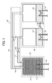
- FIG. 1 is a schematic view of a configuration of one example of the chemical heat pump according to an embodiment of the present invention.
- the chemical heat pump 100 includes a reaction member 120 accommodating the reaction material R according to an embodiment of the present invention, and an evaporator-condenser member 140 that condenses a gaseous reaction medium or evaporates a liquid reaction medium.
- the chemical heat pump 100 includes a connecting member 160 configured of connection pipes connecting the reaction member 120 and the evaporator-condenser 140.
- the reaction member 120 includes a reactor 122 and a first heat exchanger 124 provided at an outer side of the reactor 122. Due to the first heat exchanger 124, heat transfer with outside of the reactor 122 may be conducted. Normally, a heat medium flow path not shown in FIG. 1 is formed on the outside of the reactor 122 and reaction heat generated by the reactor 122 is supplied to a heat medium via the first heat exchanger 124 and the heat medium flow path.
- FIG. 1 shows an example of the chemical heat pump 100 having one reactor 122 for explanation.
- the chemical heat pump 100 may have a plurality of reactor 122.
- the evaporator-condenser member 140 includes a condenser 142 for condensing the gaseous reaction medium, an evaporator 144 for evaporating the liquid reaction medium, and a first connecting pipe 146 connecting the condenser 142 and the evaporator 144.
- the first connecting pipe 146 includes a first opening-closing valve 148.
- the first opening-closing valve 148 controls the connection between the condenser 142 and the evaporator 144. In other words, the first opening-closing valve 148 controls the movement of the reaction medium.
- the condenser 142 and the evaporator 144 include a second heat exchanger 150 and a third heat exchanger 152, respectively. Due to the second heat exchanger 150 and the third heat exchanger 152, heat transfer with outside of the condenser 142 and the evaporator 144 may be conducted, respectively. More specifically, the condenser 142 may convert water vapor to liquid water by releasing heat outside of the condenser 142 with the second heat exchanger 150. The evaporator 144 may convert liquid water to water vapor by receiving heat from outside of the evaporator 144 with the third heat exchanger 152. By operating the first connecting pipe 146 and the first opening-closing valve 148, liquid water (and water vapor) condensed by the condenser 142 may be supplied to the evaporator 144 side.
- the chemical heat pump 100 includes the connecting member 160 connecting the reaction member 120 and the evaporator-condenser member 140.
- the connecting member 160 includes a second connecting pipe 162 connecting the reactor 122 and the condenser 142 and a third connecting pipe 164 connecting the reactor 122 and the evaporator 144.
- the second connecting pipe 162 and the third connecting pipe 164 includes a second opening-closing valve 166 and a third opening-closing valve 168, respectively.
- Water vapor (and water) released in the reactor 122 may be supplied to the condenser 142 via the second connecting pipe 162.
- water vapor (and water) generated in the evaporator 144 may be supplied to the reactor 122 via the third connecting pipe 164.
- the chemical heat pump 100 condenses water vapor generated by the reacting member 120 with the condenser 142, supplies water formed of condensed water vapor to the evaporator 144, evaporates supplied water with the evaporator 144, and supplies water vapor formed from supplied water to the reacting member 120.
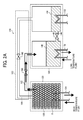
- FIG. 2A and FIG. 2B are a schematic view of an example of operation of the chemical heat pump according to an embodiment of the present invention. More specifically, FIG. 2A is a schematic view of an example of operation of the chemical heat pump in a heat storage process and FIG. 2B is a schematic view of an example of operation of the chemical heat pump in a heat release process.
- heat such as excessive exhaust heat is supplied to the reactor 122 via the first heat exchanger 124.
- a desorption reaction in which water vapor desorbs from a hydrate of the reaction material R and water vapor occurs due to supplied heat. Due to the desorption reaction, water vapor is generated in the reactor 122.
- the generated water vapor is introduced to the condenser 142 via the second connecting pipe 162.
- the second opening-closing valve 166 is in an open state.
- Water vapor introduced to the condenser 142 is discharged to an outer side of the evaporator-condenser member 140 via the second heat exchanger 150 in the condenser 142, or condensed employing low temperature heat from a low temperature heat source to liquefy into water.
- the first opening-closing valve 148 of the first connecting pipe 146 is opened and water is moved from the condenser 142 to the evaporator 144.
- Water vapor is introduced to the reactor 122 by opening the third opening-closing valve 168. Then, water vapor is introduced to the reactor 122 and the reaction material R adsorbs water vapor and becomes a hydrate. When adsorbing, heat is released in the reactor 122.
- the chemical heat pump 100 may conduct the following.
- the reaction member 120 absorbs high heat from outside and discharges heat from the evaporator-condenser member 140.
- the evaporator-condenser member 140 absorbs high heat from outside and discharges heat from the reaction member 120.
- magnesium sulfate aqueous solutions are prepared by adding 85.3 parts by weight of magnesium sulfate heptahydrate with respect to 7400 parts by weight of distilled water, 171.5 parts by weight of magnesium sulfate heptahydrate with respect to 7400 parts by weight of distilled water, and 893.8 parts by weight of magnesium sulfate heptahydrate with respect to 7400 parts by weight of distilled water.
- each magnesium sulfate aqueous solution 10,000 parts by weight of ⁇ type hemihydrate gypsum (Sakura gypsum A class, from Yoshino Gypsum Co., Ltd.) is added, mixed, and kneaded.
- ⁇ type hemihydrate gypsum Sakura gypsum A class, from Yoshino Gypsum Co., Ltd.
- Each mixture of magnesium sulfate aqueous solution and ⁇ type hemihydrate gypsum (Sakura gypsum A class, from Yoshino Gypsum Co., Ltd.) is poured in a predetermined mold and hardened.
- multiple magnesium nitrate aqueous solutions are prepared by adding 88.8 parts by weight of magnesium nitrate hexahydrate with respect to 4000 parts by weight of distilled water, 178.4 parts by weight of magnesium nitrate hexahydrate with respect to 4000 parts by weight of distilled water, and 360.5 parts by weight of magnesium nitrate hexahydrate with respect to 4000 parts by weight of distilled water.
- each magnesium nitrate aqueous solution 10,000 parts by weight of ⁇ type hemihydrate gypsum (Sakura gypsum A class, from Yoshino Gypsum Co., Ltd.) is added, mixed, and kneaded.
- ⁇ type hemihydrate gypsum (Sakura gypsum A class, from Yoshino Gypsum Co., Ltd.) is poured in a predetermined mold and hardened.
- multiple magnesium acetate aqueous solutions are prepared by adding 74.2 parts by weight of magnesium acetate tetrahydrate with respect to 4000 parts by weight of distilled water, 149.2 parts by weight of magnesium acetate tetrahydrate with respect to 4000 parts by weight of distilled water, and 301.5 parts by weight of magnesium acetate tetrahydrate with respect to 4000 parts by weight of distilled water.
- each magnesium acetate aqueous solution 10,000 parts by weight of ⁇ type hemihydrate gypsum (Sakura gypsum A class, from Yoshino Gypsum Co., Ltd.) is added, mixed, and kneaded.
- ⁇ type hemihydrate gypsum (Sakura gypsum A class, from Yoshino Gypsum Co., Ltd.) is poured in a predetermined mold and hardened.
- multiple magnesium hydroxide aqueous solutions are prepared by adding 20.2 parts by weight of magnesium hydroxide with respect to 4000 parts by weight of distilled water, 40.6 parts by weight of magnesium hydroxide with respect to 4000 parts by weight of distilled water, 82.0 parts by weight of magnesium hydroxide with respect to 4000 parts by weight of distilled water, 167.4 parts by weight of magnesium hydroxide with respect to 4000 parts by weight of distilled water, and 349.4 parts by weight of magnesium hydroxide with respect to 4000 parts by weight of distilled water.
- each magnesium hydroxide aqueous solution 10,000 parts by weight of ⁇ type hemihydrate gypsum (Sakura gypsum A class, from Yoshino Gypsum Co., Ltd.) is added, mixed, and kneaded.
- ⁇ type hemihydrate gypsum Sakura gypsum A class, from Yoshino Gypsum Co., Ltd.
- ⁇ type hemihydrate gypsum (Sakura gypsum A class, from Yoshino Gypsum Co., Ltd.) is poured in a predetermined mold and hardened.
- multiple magnesium benzoate aqueous solutions are prepared by adding 44.3 parts by weight of magnesium benzoate trihydrate with respect to 4000 parts by weight of distilled water, 110.0 parts by weight of magnesium benzoate trihydrate with respect to 4000 parts by weight of distilled water, and 223.1 parts by weight of magnesium benzoate trihydrate with respect to 4000 parts by weight of distilled water.
- each magnesium benzoate aqueous solution 10,000 parts by weight of ⁇ type hemihydrate gypsum (Sakura gypsum A class, from Yoshino Gypsum Co., Ltd.) is added, mixed, and kneaded.
- ⁇ type hemihydrate gypsum Sakura gypsum A class, from Yoshino Gypsum Co., Ltd.
- ⁇ type hemihydrate gypsum (Sakura gypsum A class, from Yoshino Gypsum Co., Ltd.) is poured in a predetermined mold and hardened.
- reaction materials anhydride of calcium sulfate of the first example are obtained.
- a comparative example is obtained by repeating the above-described preparation except for not adding the above-described magnesium compounds. Accordingly, a comparative reaction material (anhydride of calcium sulfate) of the first example is obtained.
- the load of the following conditions is conducted to change to type II anhydrous gypsum.
- a sample of each of the reaction materials and the comparative example of the first example is held in a container, the container is decompressed with a vacuum pump, and heating for 30 minutes at a temperature of 180°C is conducted. An anhydride of each sample is obtained. The anhydride of each sample is hydrated for one hour by introducing water vapor of 100 kPa in the container. It is important to note that the above-described conditions correspond to conditions in which degradation of a reaction material progress most in typical use of a chemical heat pump employing calcium sulfate, i.e., use of the chemical heat pump with water vapor pressure being 1 atmospheric pressure or less. By applying the above-described temperature and pressure conditions for a long time period, degradation of the reaction material progresses.
- reaction materials and the comparative example of the first example processed to change to type II anhydrous gypsum and each of the reaction materials and the comparative example of the first example without processing to change to type II anhydrous gypsum are left standing for one day in a thermo-humidistat tank having a temperature of 25°C and 50% RH. Amount of water absorption is compared.
- FIG. 3 is one example of a graph explaining degradation characteristics of reaction materials according to an embodiment of the present invention.
- the horizontal axis of FIG. 3 is mol fraction of magnesium with respect to calcium and magnesium in each of the reaction materials of the first example, and the vertical axis of FIG. 3 is non-degradation rate.
- Non-degradation rate of the reaction materials of the first example are determined as amount of water absorption of the reaction materials of the first example processed to change to type II anhydrous gypsum with respect to amount of water absorption of the reaction materials of the first example without processing to change to type II anhydrous gypsum.
- the higher non-degradation rate of the reaction material of the first example change to type II anhydrous gypsum does not progress even in a case in which the above-described processing to change to type II anhydrous gypsum is applied. Accordingly, the reaction material of the first example having high non-degradation rate may be said to have good degradation characteristics.
- the results of the above-described non-degradation rate are calculated with subtracting hydrate water moisture calculated from mixture amount of the magnesium compound.
- non-degradation rate of the reaction material of the first example including magnesium sulfate as the magnesium compound is higher compared to the comparative reaction material of the first example.
- Non-degradation rate is almost the same for conditions of 0.01 (1%) mol fraction of magnesium and 0.05 (5%) mol fraction of magnesium.
- a mixture ratio in which suppression of change to type II anhydrous gypsum is largest is between 0.01 (1%) mol fraction of magnesium to 0.05 (5%) mol fraction of magnesium.
- non-degradation rate of the reaction material of the first example including magnesium nitrate as the magnesium compound is higher compared to the comparative reaction material of the first example.
- a decline of 0.01 (1 %) of non-degradation rate is seen for conditions of 0.005 (0.5%) mol fraction of magnesium and 0.01 (1%) mol fraction of magnesium.
- a mixture ratio in which suppression of change to type II anhydrous gypsum is largest is around 0.005 mol fraction of magnesium.
- non-degradation rate of the reaction material of the first example including magnesium acetate as the magnesium compound is higher compared to the comparative reaction material of the first example.
- a decline of 0.02 (2%) of non-degradation rate is seen for conditions of 0.01(1%) mol fraction of magnesium and 0.02 (2%) mol fraction of magnesium.
- a mixture ratio in which suppression of change to type II anhydrous gypsum is largest is around 0.01 mol fraction of magnesium.
- non-degradation rate of the reaction material of the first example including magnesium hydroxide as the magnesium compound is higher compared to the comparative reaction material of the first example.
- Non-degradation rate is almost the same for conditions of 0.04 (4%) mol fraction of magnesium and 0.08 (8%) mol fraction of magnesium.
- a mixture ratio in which suppression of change to type II anhydrous gypsum is largest is between 0.04 (4%) mol fraction of magnesium to 0.08 (8%) mol fraction of magnesium.
- non-degradation rate of the reaction material of the first example including magnesium benzoate as the magnesium compound is higher compared to the comparative reaction material of the first example.
- the larger mol fraction of magnesium is non-degradation rate becomes larger.
- preparing a magnesium benzoate aqueous solution having a concentration beyond 0.01 (1%) mol fraction of magnesium at normal temperature is difficult.
- suppression of change to type II anhydrous gypsum is largest at 0.01 (1%) mol fraction of magnesium.
- reaction materials of the first example are understood to suppress crystal structure change to type II anhydrous gypsum even when a severe load is applied to the reaction material according to an embodiment of the present invention of the first example.
- reaction materials (anhydride of a sulphate compound) according to an embodiment of the present invention of the second example are prepared by repeating the preparation of the first example employing magnesium sulfate as the magnesium compound.
- a comparative reaction material (anhydride of calcium sulfate) of the second example as a comparative example is obtained by repeating the above-described preparation except for not adding magnesium sulfate heptahydrate.
- a load of a hydration process (heat release process) and a dehydration process (heat storage process) of the following conditions is repeated for a predetermined number of times, and the calculation of the first example is repeated to measure transition of non-degradation rate.
- the conditions are placing the reaction materials and the comparative reaction material of the second example in a thermostatic container and maintained at a temperature of 180°C, applying a hydration process of water vapor pressure of approximately 90 kPa for four hours, and applying a dehydration process of water vapor pressure of approximately 1.5 kPa for 30 minutes.
- the above-described conditions correspond to conditions in which degradation of a reaction material progress most in typical use of a chemical heat pump employing calcium sulfate, i.e., use of the chemical heat pump with water vapor pressure being 1 atmospheric pressure or less.
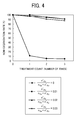
- FIG. 4 is another example of a graph explaining degradation characteristics of reaction materials according to an embodiment of the present invention.
- the horizontal axis of FIG. 4 is the number of times the above-described processing to change to type II anhydrous gypsum and dehydration process is repeated, and the vertical axis is non-degradation rate.
- the reaction materials (diamond symbol, square symbol, and triangle symbol in FIG. 4 ) according to an embodiment of the present invention of the second example have non-degradation rate of 90% or more even when the heat release process and the heat storage process are repeated.
- non-degradation rate of the comparative reaction material (x symbol in FIG. 4 ) of the second example declined to 10% or less with an application of the hydration process and the dehydration process for one time.
- a reaction material according to an embodiment of the present invention of the third example and a comparative reaction material of the third example are prepared by repeating the preparation of the first example.
- the reaction material of the third example having 0.01 (1%) mol fraction of magnesium is applied with the above-described hydration process and dehydration process for three times as a heat load, sufficiently dehydrated at a temperature of 150°C to form into an anhydride, left standing in a temperature of 25°C and 50% RH, and analyzed with X-ray diffraction (XRD).
- XRD X-ray diffraction
- type III calcium sulfate changes to a hemihydrate and type II calcium sulfate is maintained as an anhydride when left standing in a temperature of 25°C and 50% RH.
- a XRD peak strength of hemihydrate gypsum and a XRD peak strength of type II anhydrous gypsum a result that is the same as comparing a XRD peak strength of type III anhydrous gypsum and a XRD peak strength of type II anhydrous gypsum is obtained.
- FIG. 5A and FIG. 5B are examples of a graph explaining X-ray diffraction (XRD) results of the reaction material of the third example employing magnesium sulfate as the magnesium compound. More specifically, FIG. 5A is the result of the reaction material of the third example and FIG. 5B is the result of the comparative reaction material of the third example.
- the thick line represents the reaction material of the third example without applying the above-described hydration process and dehydration process, and the thin line represents the reaction material of the third example after applying the above-described hydration process and dehydration process.
- the circle symbol represents a theoretical peak position of calcium sulfate hemihydrate
- the triangle symbol represents a theoretical peak position of type II calcium sulfate.
- the reaction material of the third example without applying the heat load exhibits a peak of type III calcium sulfate.
- the reaction material of the third example applied with the heat load also exhibits a peak of type III calcium sulfate.
- phase change to type II calcium sulfate does not occur because at least one part of calcium site of type III calcium sulfate is substituted with magnesium making a deformed crystal lattice of calcium sulfate.
- the comparative reaction material of the third example without applying the heat load exhibits a main peak of type III calcium sulfate and a sub-peak of type II calcium sulfate. It is understood that the sub-peak of type II calcium sulfate is due to change of calcium sulfate to type II calcium sulfate at manufacture of the reaction material of the third example. Accordingly, it is understood that the reaction material of the third example represented by FIG. 5A suppress change of calcium sulfate to type II calcium sulfate even at manufacture of the reaction material of the third example.
- the comparative reaction material of the third example applied with the heat load exhibits a weaker peak of type III calcium sulfate and a strong peak of type II calcium sulfate.
- the comparative reaction material of the third example is subjected to repeated processing to change to type II calcium sulfate and dehydration process, it is understood that crystal structure change from type III calcium sulfate to type II calcium sulfate may easily progress.
- Type II calcium sulfate does not react with water vapor and is unsuitable for the reaction material of the chemical heat pump.
- the reaction material of the third example suppresses change to type II calcium sulfate and maintain crystal structure of type III calcium sulfate. Accordingly, the reaction material of the third example has a characteristic desired by the chemical heat pump of being difficult to degrade and may be said to be suitable for the reaction material of the chemical heat pump.
- reaction materials according to an embodiment of the present invention of the fourth example are prepared by repeating the preparation of the first example.
- a comparative reaction material (anhydride of calcium sulfate) of the fourth example as a comparative example is obtained by repeating the above-described preparation except for not adding a magnesium compound.
- a heat medium having a temperature of 150°C is introduced to the reactor 122 from the first heat exchanger 124 and water moisture is evaporated from the reaction materials of the fourth example.
- the evaporated water moisture is introduced to the condenser 142 via the second connecting pipe 162 and is liquefied by setting the condenser 142 to a water vapor pressure of 1.5 kPa.
- the heat storage process is conducted for 10 minutes.
- the evaporator 144 is set to a water vapor pressure of 90 kPa and water vapor is exposed (supplied) to the reaction materials of the fourth example via the third connecting pipe 164.
- the reaction materials of the fourth example having absorbed the water vapor generates a heat of approximately 185°C, raises the temperature of the heat medium having a temperature of 150°C introduced to the reactor 122, and raised temperature heat is extracted at the first heat exchanger 124.
- the heat release process is conducted for 10 minutes.
- the above-described heat storage process and heat release process is considered as one heat storage-release process, and an operation of the heat storage-release process is repeated twenty times. It is important to note that the above-described conditions correspond to conditions near to actual operation in typical use of a chemical heat pump employing calcium sulfate, i.e., use of the chemical heat pump with water vapor pressure being 1 atmospheric pressure or less.
- the above-described conditions are conditions in which degradation progress of a reaction material is slower than the conditions of the load of the first and second examples.
- ratio of type II calcium sulfate in the reaction materials of the fourth example is evaluated with XRD measurement. It is important to note that ratio may be determined by comparing a XRD pattern of a reaction material and a XRD pattern of type III anhydrous gypsum alone and type II anhydrous gypsum alone.
- FIG. 6 is another example of a graph explaining X-ray diffraction (XRD) results of a reaction material according to an embodiment of the present invention.
- XRD X-ray diffraction
- XRD pattern of crystal other than type III anhydrous gypsum of the reaction materials of the fourth example after repeating heat storage-release process is not observed.
- XRD pattern of crystal other than hemihydrate gypsum of the reaction materials of the fourth example before conducting repeated heat storage-release process is not observed.
- the comparative reaction material of the fourth example after repeating the above-described heat storage-release process twenty times exhibited a ratio of type II anhydrous gypsum of 47%.
- the reaction material 1 of the fourth example exhibited a ratio of type II anhydrous gypsum of 6%.
- the other reaction materials of the fourth example exhibited a smaller ratio of type II anhydrous gypsum compared to the comparative reaction material of the fourth example. From the results, it is understood that by mixing and kneading the magnesium compounds to the reaction materials of the fourth example, phase change of crystal structure from type III anhydrous gypsum to type II anhydrous gypsum is suppressed.
- reaction materials according to an embodiment of the present invention of the fifth example are prepared by repeating the preparation of the first example.
- a comparative reaction material (anhydride of calcium sulfate) of the fifth example as a comparative example is obtained by repeating the above-described preparation except for not adding a magnesium compound.
- table 2 Shown in table 2 are the type of magnesium compounds and the content amount (mixture ratio) of the magnesium compounds at manufacture of the reaction materials of the fifth example. Further, reaction material 1, reaction material 2, and reaction material 3 of the fourth example and the comparative reaction material of the fourth example are manufactured and shown in table 2 indicated with the same reference name and number of reaction material 1, reaction material 2, reaction material 3, and comparative reaction material.
- the load of the fourth example is applied except for the number of times the load is repeated is changed from twenty times to one hundred times. Accordingly, ratio of type II anhydrous gypsum is obtained.
- the ratio of type II anhydrous gypsum of the reaction materials and the comparative reaction material of the fourth example are 86%, 39%, 52%, and 49%, respectively.
- the ratio of type II anhydrous gypsum of the reaction materials of the fifth example, reaction material 9, reaction material 10, reaction material 11, and reaction material 12 are 23%, 9%, 16%, and 13%, respectively.
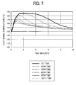
- FIG. 7 is another example of a graph explaining degradation characteristics of a comparative reaction material according to an embodiment of the present invention. More specifically, FIG. 7 is a graph indicating temporal change of temperature of the comparative reaction material of the fifth example in the heat release process. The horizontal axis of FIG. 7 is time period of the heat release process and the vertical axis is temperature of the comparative reaction material of the fifth example.
- the comparative reaction material of the fifth example exhibits a heat generation characteristic of 185°C in the first application of the heat release process.
- temperature of heat generated by the comparative reaction material of the fifth example declines as the number of times of applying the heat release process increases.
- the heat generation characteristic of the comparative reaction material of the fifth example is 165°C.
- time of heat generation of the comparative reaction material of the fifth example declines as the number of times the application of the load increases. It is understood that decline in temperature of generated heat and decline in time of heat generation is due to structure change of type III anhydrous gypsum to type II anhydrous gypsum having a lower heat storage-release characteristic.
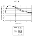
- FIG. 8 is another example of a graph explaining degradation characteristics of a reaction material according to an embodiment of the present invention. More specifically, FIG. 8 is a graph indicating temporal change of temperature of the reaction material 10 of the fifth example in the heat release process. The horizontal axis of FIG. 8 is time period of the heat release process and the vertical axis is temperature of the comparative reaction material of the fifth example.
- the reaction material 10 of the fifth example exhibits a heat generation characteristic of 185°C in the first application of the heat release process. Temperature of heat generated by the reaction material 10 of the fifth example almost does not decline even when the number of times of applying the heat release process increases. At the one hundredth time of the heat release process, the heat generation characteristic of the reaction material 10 of the fifth example is 185°C. In addition, time of heat generation of the reaction material 10 of the fifth example almost does not decline even at the one hundredth time of application of the heat release process compared to the first application of the heat release process.
- reaction materials of the fifth example suppresses crystal structure change from type III calcium sulfate to type II calcium sulfate even when heat storage-release process is repeated.
- the reaction materials of the fifth example are reaction materials for the chemical heat pump having good heat storage-release characteristics and good degradation characteristics.
Landscapes
- Engineering & Computer Science (AREA)
- Chemical & Material Sciences (AREA)
- Physics & Mathematics (AREA)
- Thermal Sciences (AREA)
- Mechanical Engineering (AREA)
- General Engineering & Computer Science (AREA)
- Chemical Kinetics & Catalysis (AREA)
- Organic Chemistry (AREA)
- Materials Engineering (AREA)
- Combustion & Propulsion (AREA)
- General Chemical & Material Sciences (AREA)
- Dispersion Chemistry (AREA)
- Sorption Type Refrigeration Machines (AREA)
- Compounds Of Alkaline-Earth Elements, Aluminum Or Rare-Earth Metals (AREA)
- Curing Cements, Concrete, And Artificial Stone (AREA)
Applications Claiming Priority (2)
| Application Number | Priority Date | Filing Date | Title |
|---|---|---|---|
| JP2013029185 | 2013-02-18 | ||
| JP2013272520A JP6248623B2 (ja) | 2013-02-18 | 2013-12-27 | 反応材及びケミカルヒートポンプ |
Publications (3)
| Publication Number | Publication Date |
|---|---|
| EP2767570A2 true EP2767570A2 (de) | 2014-08-20 |
| EP2767570A3 EP2767570A3 (de) | 2017-03-08 |
| EP2767570B1 EP2767570B1 (de) | 2018-04-04 |
Family
ID=50101776
Family Applications (1)
| Application Number | Title | Priority Date | Filing Date |
|---|---|---|---|
| EP14155172.1A Not-in-force EP2767570B1 (de) | 2013-02-18 | 2014-02-14 | Reaktionsmaterial und chemische Wärmepumpe |
Country Status (4)
| Country | Link |
|---|---|
| US (1) | US9243179B2 (de) |
| EP (1) | EP2767570B1 (de) |
| JP (1) | JP6248623B2 (de) |
| CN (1) | CN103992771B (de) |
Cited By (1)
| Publication number | Priority date | Publication date | Assignee | Title |
|---|---|---|---|---|
| EP3037630A1 (de) * | 2014-12-22 | 2016-06-29 | NGK Insulators, Ltd. | Chemische wärmepumpe |
Families Citing this family (11)
| Publication number | Priority date | Publication date | Assignee | Title |
|---|---|---|---|---|
| JP6248623B2 (ja) * | 2013-02-18 | 2017-12-20 | 株式会社リコー | 反応材及びケミカルヒートポンプ |
| JP6515685B2 (ja) * | 2015-06-02 | 2019-05-22 | 株式会社豊田中央研究所 | 蒸発凝縮器、蒸発器及び凝縮器 |
| JP2017002200A (ja) * | 2015-06-11 | 2017-01-05 | 株式会社リコー | ケミカルヒートポンプ用反応材及びその製造方法 |
| KR102599490B1 (ko) * | 2017-06-30 | 2023-11-07 | 다테호 가가쿠 고교 가부시키가이샤 | 화학 축열재와 그 제조 방법, 및 화학 열 펌프와 그 운전 방법 |
| JP6471947B1 (ja) * | 2017-06-30 | 2019-02-20 | タテホ化学工業株式会社 | 化学蓄熱材及びその製造方法、並びにケミカルヒートポンプ及びその運転方法 |
| JP7190702B2 (ja) * | 2019-03-28 | 2022-12-16 | 宇部マテリアルズ株式会社 | 脱水促進材 |
| JP2021080404A (ja) | 2019-11-21 | 2021-05-27 | 株式会社リコー | 液体組成物及び電気化学素子の製造方法 |
| JP7679969B2 (ja) * | 2019-11-29 | 2025-05-20 | タテホ化学工業株式会社 | 化学蓄熱材及びその製造方法、並びにケミカルヒートポンプ |
| GR1010488B (el) * | 2022-05-30 | 2023-06-16 | Αριστοτελειο Πανεπιστημιο Θεσσαλονικης - Ειδικος Λογαριασμος Κονδυλιων Ερευνας, | Δοχειο ενθυλακωσης για συστημα αποθηκευσης θερμικης ενεργειας με μακροενθυλακωση |
| MA56957B1 (fr) * | 2022-06-02 | 2024-04-30 | Univ Mohammed Vi Polytechnique | Phosphogypse en tant que materiau utilise pour le stockage d’energie thermique |
| CN117433345B (zh) * | 2023-10-09 | 2024-06-18 | 广州市鑫湖能源科技有限公司 | 蓄冷储能系统及蓄冷储能控制方法 |
Citations (2)
| Publication number | Priority date | Publication date | Assignee | Title |
|---|---|---|---|---|
| JPH0926225A (ja) | 1995-07-11 | 1997-01-28 | Meidensha Corp | ケミカルヒートポンプ |
| JP2010185035A (ja) | 2009-02-13 | 2010-08-26 | Toyota Central R&D Labs Inc | 蓄熱体粉末の製造方法、並びに、化学蓄熱装置及びその製造方法 |
Family Cites Families (28)
| Publication number | Priority date | Publication date | Assignee | Title |
|---|---|---|---|---|
| JPS6042563A (ja) | 1983-08-17 | 1985-03-06 | 松下電器産業株式会社 | ケミカルヒ−トポンプ |
| JPS6050362A (ja) | 1983-08-30 | 1985-03-20 | 松下電器産業株式会社 | ケミカルヒ−トポンプ |
| EP0141550A1 (de) * | 1983-10-13 | 1985-05-15 | Sumitomo Chemical Company, Limited | Zusammensetzung zur Wärmespeicherung |
| JPS6289786A (ja) * | 1985-10-15 | 1987-04-24 | Matsushita Electric Ind Co Ltd | 蓄熱材 |
| US5598721A (en) * | 1989-03-08 | 1997-02-04 | Rocky Research | Heating and air conditioning systems incorporating solid-vapor sorption reactors capable of high reaction rates |
| JP3757041B2 (ja) * | 1997-10-17 | 2006-03-22 | 株式会社豊田中央研究所 | 蒸気吸放出材料 |
| JP2000104045A (ja) * | 1998-09-29 | 2000-04-11 | Mi Tec:Kk | 融雪防滑剤及びその製法 |
| JP4145051B2 (ja) * | 2002-01-22 | 2008-09-03 | 株式会社電業社機械製作所 | ケミカルヒートポンプ装置およびその運転方法 |
| JP4694810B2 (ja) * | 2004-09-08 | 2011-06-08 | 株式会社日本触媒 | 吸水性樹脂を主成分とする植物育成用保水材 |
| JP2008527102A (ja) * | 2005-01-07 | 2008-07-24 | コーニンクレッカ フィリップス エレクトロニクス エヌ ヴィ | 保護コーティングを備えた誘電バリア放電ランプ |
| JP4868820B2 (ja) | 2005-10-20 | 2012-02-01 | シャープ株式会社 | 化合物太陽電池及び製造方法 |
| JP4776391B2 (ja) * | 2006-02-17 | 2011-09-21 | 大阪瓦斯株式会社 | 排熱利用システム |
| EP1990595A1 (de) * | 2006-03-01 | 2008-11-12 | Matsushita Electric Industrial Co., Ltd. | Wärmestauungsverfahren und wärmestauungssystem |
| WO2008000855A1 (es) * | 2006-06-27 | 2008-01-03 | Aditivos Del Cemento, S.L. | Procedimiento de obtencion de un aditivo para el cemento y aditivo asi conseguido |
| JP4008490B1 (ja) * | 2006-10-02 | 2007-11-14 | 株式会社エネルダイン | 発熱剤 |
| JP5227084B2 (ja) * | 2008-05-27 | 2013-07-03 | 愛三工業株式会社 | 造粒蓄熱材とその製造方法 |
| JP2012516578A (ja) | 2009-01-28 | 2012-07-19 | マイクロリンク デバイセズ, インク. | 酸化窓層を備えた高効率のiii−v族化合物半導体の太陽電池装置 |
| JP2010230268A (ja) | 2009-03-27 | 2010-10-14 | Toyoda Gosei Co Ltd | ケミカルヒートポンプ装置及びその使用方法 |
| JP2011163730A (ja) | 2010-02-15 | 2011-08-25 | Chiba Univ | ケミカルヒートポンプ及びそれを用いたハイブリッド冷凍システム |
| JP5747479B2 (ja) * | 2010-11-04 | 2015-07-15 | アイシン精機株式会社 | 暖房装置 |
| JP2012145252A (ja) | 2011-01-11 | 2012-08-02 | Daihatsu Motor Co Ltd | ケミカルヒートポンプ |
| JP5772172B2 (ja) * | 2011-04-13 | 2015-09-02 | 株式会社リコー | 熱回収利用システム及び熱回収利用方法 |
| JP6016208B2 (ja) * | 2012-03-21 | 2016-10-26 | 国立大学法人 千葉大学 | ケミカルヒートポンプ及びその制御方法 |
| JP6248623B2 (ja) * | 2013-02-18 | 2017-12-20 | 株式会社リコー | 反応材及びケミカルヒートポンプ |
| JP6446782B2 (ja) | 2013-03-14 | 2019-01-09 | 株式会社リコー | 化合物半導体太陽電池、及び、化合物半導体太陽電池の製造方法 |
| WO2014142340A1 (en) | 2013-03-14 | 2014-09-18 | Ricoh Company, Ltd. | Compound semiconductor photovoltaic cell and manufacturing method of the same |
| JP2015038952A (ja) | 2013-07-16 | 2015-02-26 | 株式会社リコー | 化合物半導体太陽電池、及び、化合物半導体太陽電池の製造方法 |
| JP6550691B2 (ja) | 2013-07-30 | 2019-07-31 | 株式会社リコー | 化合物半導体太陽電池 |
-
2013
- 2013-12-27 JP JP2013272520A patent/JP6248623B2/ja not_active Expired - Fee Related
-
2014
- 2014-02-14 EP EP14155172.1A patent/EP2767570B1/de not_active Not-in-force
- 2014-02-14 US US14/180,426 patent/US9243179B2/en not_active Expired - Fee Related
- 2014-02-18 CN CN201410054842.5A patent/CN103992771B/zh not_active Expired - Fee Related
Patent Citations (2)
| Publication number | Priority date | Publication date | Assignee | Title |
|---|---|---|---|---|
| JPH0926225A (ja) | 1995-07-11 | 1997-01-28 | Meidensha Corp | ケミカルヒートポンプ |
| JP2010185035A (ja) | 2009-02-13 | 2010-08-26 | Toyota Central R&D Labs Inc | 蓄熱体粉末の製造方法、並びに、化学蓄熱装置及びその製造方法 |
Cited By (2)
| Publication number | Priority date | Publication date | Assignee | Title |
|---|---|---|---|---|
| EP3037630A1 (de) * | 2014-12-22 | 2016-06-29 | NGK Insulators, Ltd. | Chemische wärmepumpe |
| US9873826B2 (en) | 2014-12-22 | 2018-01-23 | Ngk Insulators, Ltd. | Chemical heat pump |
Also Published As
| Publication number | Publication date |
|---|---|
| CN103992771A (zh) | 2014-08-20 |
| JP2014177619A (ja) | 2014-09-25 |
| EP2767570A3 (de) | 2017-03-08 |
| US9243179B2 (en) | 2016-01-26 |
| CN103992771B (zh) | 2017-07-14 |
| JP6248623B2 (ja) | 2017-12-20 |
| EP2767570B1 (de) | 2018-04-04 |
| US20140231698A1 (en) | 2014-08-21 |
Similar Documents
| Publication | Publication Date | Title |
|---|---|---|
| EP2767570B1 (de) | Reaktionsmaterial und chemische Wärmepumpe | |
| US8795626B2 (en) | Zeolite having copper and alkali earth metal supported thereon | |
| Kubota et al. | Enhancement of hydration rate of LiOH by combining with mesoporous carbon for Low-temperature chemical heat storage | |
| KR101859112B1 (ko) | 다공성 제올라이트-금속염 복합체를 이용한 열화학식 축열소재 및 이의 제조방법 | |
| US11045785B2 (en) | Metal-organic framework, method for preparing the same, and adsorption device employing the same | |
| JP2015232101A (ja) | ケミカルヒートポンプ用反応材、ケミカルヒートポンプ | |
| KR102304623B1 (ko) | 다공성 흡착제 및 이의 제조 방법 | |
| EP2749624B1 (de) | Chemische wärmespeicherstruktur enthaltend ein chemisches wärmespeichermaterial | |
| KR102599491B1 (ko) | 화학 축열재와 그 제조 방법, 및 화학 열 펌프와 그 운전 방법 | |
| EP4417303A1 (de) | Ethylbenzoldehydrierungskatalysator, herstellungsverfahren dafür und verwendung davon | |
| JP2017002200A (ja) | ケミカルヒートポンプ用反応材及びその製造方法 | |
| KR20210054745A (ko) | 전자기파를 이용한 안정성이 개선된 이산화탄소 포집용 다공성 나노소재 | |
| KR20200121305A (ko) | 화학 축열재 및 그의 제조방법 | |
| CN100479921C (zh) | 一种球形尖晶石骨架结构材料及其制备方法 | |
| Włódarkiewicz et al. | The dissolution of potassium sodium niobate (KNN) in aqueous media towards sustainable electroceramics sintering | |
| KR102307019B1 (ko) | 내구성 및 작업성이 향상된 수화열 저감재. | |
| RU2729004C1 (ru) | Материал для аккумулирования тепла, способ изготовления материала для аккумулирования тепла и химический тепловой насос | |
| JP5451393B2 (ja) | 硫化亜鉛成型体及びその製造方法 | |
| JP2016023193A (ja) | ケミカルヒートポンプ用反応材とその製造方法、ケミカルヒートポンプ | |
| JP6815915B2 (ja) | 化学蓄熱材及びその製造方法 | |
| CN113754328B (zh) | 一种结构稳定的半水-无水硫酸钙混合物及其制备方法 | |
| JP2017071698A (ja) | 蓄熱材料およびその製造方法 | |
| EP3591023A1 (de) | Wärmespeichermaterial mit metallsalz von cyanursäure | |
| KR20240113642A (ko) | 나노복합소재 및 이의 제조방법 | |
| KR20230171763A (ko) | 이산화탄소 흡착용 이중 금속 유기 골격체 및 이의 제조방법 |
Legal Events
| Date | Code | Title | Description |
|---|---|---|---|
| PUAI | Public reference made under article 153(3) epc to a published international application that has entered the european phase |
Free format text: ORIGINAL CODE: 0009012 |
|
| 17P | Request for examination filed |
Effective date: 20140214 |
|
| AK | Designated contracting states |
Kind code of ref document: A2 Designated state(s): AL AT BE BG CH CY CZ DE DK EE ES FI FR GB GR HR HU IE IS IT LI LT LU LV MC MK MT NL NO PL PT RO RS SE SI SK SM TR |
|
| AX | Request for extension of the european patent |
Extension state: BA ME |
|
| PUAL | Search report despatched |
Free format text: ORIGINAL CODE: 0009013 |
|
| AK | Designated contracting states |
Kind code of ref document: A3 Designated state(s): AL AT BE BG CH CY CZ DE DK EE ES FI FR GB GR HR HU IE IS IT LI LT LU LV MC MK MT NL NO PL PT RO RS SE SI SK SM TR |
|
| AX | Request for extension of the european patent |
Extension state: BA ME |
|
| RIC1 | Information provided on ipc code assigned before grant |
Ipc: C09K 5/16 20060101AFI20170130BHEP Ipc: F28D 20/00 20060101ALI20170130BHEP |
|
| GRAP | Despatch of communication of intention to grant a patent |
Free format text: ORIGINAL CODE: EPIDOSNIGR1 |
|
| STAA | Information on the status of an ep patent application or granted ep patent |
Free format text: STATUS: GRANT OF PATENT IS INTENDED |
|
| INTG | Intention to grant announced |
Effective date: 20170907 |
|
| GRAS | Grant fee paid |
Free format text: ORIGINAL CODE: EPIDOSNIGR3 |
|
| RIN1 | Information on inventor provided before grant (corrected) |
Inventor name: MASUZAWA, MASAHIRO Inventor name: AMAN, YASUTOMO Inventor name: SHIREN, YOHEI Inventor name: OHKURA, HIROKO Inventor name: OHBA, YOSHIFUMI |
|
| GRAA | (expected) grant |
Free format text: ORIGINAL CODE: 0009210 |
|
| STAA | Information on the status of an ep patent application or granted ep patent |
Free format text: STATUS: THE PATENT HAS BEEN GRANTED |
|
| AK | Designated contracting states |
Kind code of ref document: B1 Designated state(s): AL AT BE BG CH CY CZ DE DK EE ES FI FR GB GR HR HU IE IS IT LI LT LU LV MC MK MT NL NO PL PT RO RS SE SI SK SM TR |
|
| REG | Reference to a national code |
Ref country code: GB Ref legal event code: FG4D |
|
| REG | Reference to a national code |
Ref country code: CH Ref legal event code: EP |
|
| REG | Reference to a national code |
Ref country code: AT Ref legal event code: REF Ref document number: 985583 Country of ref document: AT Kind code of ref document: T Effective date: 20180415 |
|
| REG | Reference to a national code |
Ref country code: IE Ref legal event code: FG4D |
|
| REG | Reference to a national code |
Ref country code: DE Ref legal event code: R096 Ref document number: 602014023194 Country of ref document: DE |
|
| REG | Reference to a national code |
Ref country code: NL Ref legal event code: MP Effective date: 20180404 |
|
| REG | Reference to a national code |
Ref country code: LT Ref legal event code: MG4D |
|
| PG25 | Lapsed in a contracting state [announced via postgrant information from national office to epo] |
Ref country code: NL Free format text: LAPSE BECAUSE OF FAILURE TO SUBMIT A TRANSLATION OF THE DESCRIPTION OR TO PAY THE FEE WITHIN THE PRESCRIBED TIME-LIMIT Effective date: 20180404 |
|
| PG25 | Lapsed in a contracting state [announced via postgrant information from national office to epo] |
Ref country code: NO Free format text: LAPSE BECAUSE OF FAILURE TO SUBMIT A TRANSLATION OF THE DESCRIPTION OR TO PAY THE FEE WITHIN THE PRESCRIBED TIME-LIMIT Effective date: 20180704 Ref country code: BG Free format text: LAPSE BECAUSE OF FAILURE TO SUBMIT A TRANSLATION OF THE DESCRIPTION OR TO PAY THE FEE WITHIN THE PRESCRIBED TIME-LIMIT Effective date: 20180704 Ref country code: PL Free format text: LAPSE BECAUSE OF FAILURE TO SUBMIT A TRANSLATION OF THE DESCRIPTION OR TO PAY THE FEE WITHIN THE PRESCRIBED TIME-LIMIT Effective date: 20180404 Ref country code: LT Free format text: LAPSE BECAUSE OF FAILURE TO SUBMIT A TRANSLATION OF THE DESCRIPTION OR TO PAY THE FEE WITHIN THE PRESCRIBED TIME-LIMIT Effective date: 20180404 Ref country code: ES Free format text: LAPSE BECAUSE OF FAILURE TO SUBMIT A TRANSLATION OF THE DESCRIPTION OR TO PAY THE FEE WITHIN THE PRESCRIBED TIME-LIMIT Effective date: 20180404 Ref country code: AL Free format text: LAPSE BECAUSE OF FAILURE TO SUBMIT A TRANSLATION OF THE DESCRIPTION OR TO PAY THE FEE WITHIN THE PRESCRIBED TIME-LIMIT Effective date: 20180404 Ref country code: SE Free format text: LAPSE BECAUSE OF FAILURE TO SUBMIT A TRANSLATION OF THE DESCRIPTION OR TO PAY THE FEE WITHIN THE PRESCRIBED TIME-LIMIT Effective date: 20180404 Ref country code: FI Free format text: LAPSE BECAUSE OF FAILURE TO SUBMIT A TRANSLATION OF THE DESCRIPTION OR TO PAY THE FEE WITHIN THE PRESCRIBED TIME-LIMIT Effective date: 20180404 |
|
| PG25 | Lapsed in a contracting state [announced via postgrant information from national office to epo] |
Ref country code: LV Free format text: LAPSE BECAUSE OF FAILURE TO SUBMIT A TRANSLATION OF THE DESCRIPTION OR TO PAY THE FEE WITHIN THE PRESCRIBED TIME-LIMIT Effective date: 20180404 Ref country code: RS Free format text: LAPSE BECAUSE OF FAILURE TO SUBMIT A TRANSLATION OF THE DESCRIPTION OR TO PAY THE FEE WITHIN THE PRESCRIBED TIME-LIMIT Effective date: 20180404 Ref country code: GR Free format text: LAPSE BECAUSE OF FAILURE TO SUBMIT A TRANSLATION OF THE DESCRIPTION OR TO PAY THE FEE WITHIN THE PRESCRIBED TIME-LIMIT Effective date: 20180705 Ref country code: HR Free format text: LAPSE BECAUSE OF FAILURE TO SUBMIT A TRANSLATION OF THE DESCRIPTION OR TO PAY THE FEE WITHIN THE PRESCRIBED TIME-LIMIT Effective date: 20180404 |
|
| REG | Reference to a national code |
Ref country code: AT Ref legal event code: MK05 Ref document number: 985583 Country of ref document: AT Kind code of ref document: T Effective date: 20180404 |
|
| PG25 | Lapsed in a contracting state [announced via postgrant information from national office to epo] |
Ref country code: PT Free format text: LAPSE BECAUSE OF FAILURE TO SUBMIT A TRANSLATION OF THE DESCRIPTION OR TO PAY THE FEE WITHIN THE PRESCRIBED TIME-LIMIT Effective date: 20180806 |
|
| REG | Reference to a national code |
Ref country code: DE Ref legal event code: R097 Ref document number: 602014023194 Country of ref document: DE |
|
| PG25 | Lapsed in a contracting state [announced via postgrant information from national office to epo] |
Ref country code: EE Free format text: LAPSE BECAUSE OF FAILURE TO SUBMIT A TRANSLATION OF THE DESCRIPTION OR TO PAY THE FEE WITHIN THE PRESCRIBED TIME-LIMIT Effective date: 20180404 Ref country code: AT Free format text: LAPSE BECAUSE OF FAILURE TO SUBMIT A TRANSLATION OF THE DESCRIPTION OR TO PAY THE FEE WITHIN THE PRESCRIBED TIME-LIMIT Effective date: 20180404 Ref country code: DK Free format text: LAPSE BECAUSE OF FAILURE TO SUBMIT A TRANSLATION OF THE DESCRIPTION OR TO PAY THE FEE WITHIN THE PRESCRIBED TIME-LIMIT Effective date: 20180404 Ref country code: SK Free format text: LAPSE BECAUSE OF FAILURE TO SUBMIT A TRANSLATION OF THE DESCRIPTION OR TO PAY THE FEE WITHIN THE PRESCRIBED TIME-LIMIT Effective date: 20180404 Ref country code: CZ Free format text: LAPSE BECAUSE OF FAILURE TO SUBMIT A TRANSLATION OF THE DESCRIPTION OR TO PAY THE FEE WITHIN THE PRESCRIBED TIME-LIMIT Effective date: 20180404 Ref country code: RO Free format text: LAPSE BECAUSE OF FAILURE TO SUBMIT A TRANSLATION OF THE DESCRIPTION OR TO PAY THE FEE WITHIN THE PRESCRIBED TIME-LIMIT Effective date: 20180404 |
|
| PLBE | No opposition filed within time limit |
Free format text: ORIGINAL CODE: 0009261 |
|
| STAA | Information on the status of an ep patent application or granted ep patent |
Free format text: STATUS: NO OPPOSITION FILED WITHIN TIME LIMIT |
|
| PG25 | Lapsed in a contracting state [announced via postgrant information from national office to epo] |
Ref country code: SM Free format text: LAPSE BECAUSE OF FAILURE TO SUBMIT A TRANSLATION OF THE DESCRIPTION OR TO PAY THE FEE WITHIN THE PRESCRIBED TIME-LIMIT Effective date: 20180404 Ref country code: IT Free format text: LAPSE BECAUSE OF FAILURE TO SUBMIT A TRANSLATION OF THE DESCRIPTION OR TO PAY THE FEE WITHIN THE PRESCRIBED TIME-LIMIT Effective date: 20180404 |
|
| 26N | No opposition filed |
Effective date: 20190107 |
|
| PG25 | Lapsed in a contracting state [announced via postgrant information from national office to epo] |
Ref country code: SI Free format text: LAPSE BECAUSE OF FAILURE TO SUBMIT A TRANSLATION OF THE DESCRIPTION OR TO PAY THE FEE WITHIN THE PRESCRIBED TIME-LIMIT Effective date: 20180404 |
|
| REG | Reference to a national code |
Ref country code: CH Ref legal event code: PL |
|
| PG25 | Lapsed in a contracting state [announced via postgrant information from national office to epo] |
Ref country code: LU Free format text: LAPSE BECAUSE OF NON-PAYMENT OF DUE FEES Effective date: 20190214 Ref country code: MC Free format text: LAPSE BECAUSE OF FAILURE TO SUBMIT A TRANSLATION OF THE DESCRIPTION OR TO PAY THE FEE WITHIN THE PRESCRIBED TIME-LIMIT Effective date: 20180404 |
|
| REG | Reference to a national code |
Ref country code: BE Ref legal event code: MM Effective date: 20190228 |
|
| REG | Reference to a national code |
Ref country code: IE Ref legal event code: MM4A |
|
| PG25 | Lapsed in a contracting state [announced via postgrant information from national office to epo] |
Ref country code: LI Free format text: LAPSE BECAUSE OF NON-PAYMENT OF DUE FEES Effective date: 20190228 Ref country code: CH Free format text: LAPSE BECAUSE OF NON-PAYMENT OF DUE FEES Effective date: 20190228 |
|
| PG25 | Lapsed in a contracting state [announced via postgrant information from national office to epo] |
Ref country code: IE Free format text: LAPSE BECAUSE OF NON-PAYMENT OF DUE FEES Effective date: 20190214 |
|
| PG25 | Lapsed in a contracting state [announced via postgrant information from national office to epo] |
Ref country code: BE Free format text: LAPSE BECAUSE OF NON-PAYMENT OF DUE FEES Effective date: 20190228 |
|
| PG25 | Lapsed in a contracting state [announced via postgrant information from national office to epo] |
Ref country code: TR Free format text: LAPSE BECAUSE OF FAILURE TO SUBMIT A TRANSLATION OF THE DESCRIPTION OR TO PAY THE FEE WITHIN THE PRESCRIBED TIME-LIMIT Effective date: 20180404 |
|
| PGFP | Annual fee paid to national office [announced via postgrant information from national office to epo] |
Ref country code: DE Payment date: 20200219 Year of fee payment: 7 Ref country code: GB Payment date: 20200219 Year of fee payment: 7 |
|
| PG25 | Lapsed in a contracting state [announced via postgrant information from national office to epo] |
Ref country code: MT Free format text: LAPSE BECAUSE OF NON-PAYMENT OF DUE FEES Effective date: 20190214 |
|
| PGFP | Annual fee paid to national office [announced via postgrant information from national office to epo] |
Ref country code: FR Payment date: 20200219 Year of fee payment: 7 |
|
| PG25 | Lapsed in a contracting state [announced via postgrant information from national office to epo] |
Ref country code: CY Free format text: LAPSE BECAUSE OF FAILURE TO SUBMIT A TRANSLATION OF THE DESCRIPTION OR TO PAY THE FEE WITHIN THE PRESCRIBED TIME-LIMIT Effective date: 20180404 |
|
| PG25 | Lapsed in a contracting state [announced via postgrant information from national office to epo] |
Ref country code: IS Free format text: LAPSE BECAUSE OF FAILURE TO SUBMIT A TRANSLATION OF THE DESCRIPTION OR TO PAY THE FEE WITHIN THE PRESCRIBED TIME-LIMIT Effective date: 20180804 |
|
| PG25 | Lapsed in a contracting state [announced via postgrant information from national office to epo] |
Ref country code: HU Free format text: LAPSE BECAUSE OF FAILURE TO SUBMIT A TRANSLATION OF THE DESCRIPTION OR TO PAY THE FEE WITHIN THE PRESCRIBED TIME-LIMIT; INVALID AB INITIO Effective date: 20140214 |
|
| REG | Reference to a national code |
Ref country code: DE Ref legal event code: R119 Ref document number: 602014023194 Country of ref document: DE |
|
| GBPC | Gb: european patent ceased through non-payment of renewal fee |
Effective date: 20210214 |
|
| PG25 | Lapsed in a contracting state [announced via postgrant information from national office to epo] |
Ref country code: FR Free format text: LAPSE BECAUSE OF NON-PAYMENT OF DUE FEES Effective date: 20210228 Ref country code: GB Free format text: LAPSE BECAUSE OF NON-PAYMENT OF DUE FEES Effective date: 20210214 Ref country code: DE Free format text: LAPSE BECAUSE OF NON-PAYMENT OF DUE FEES Effective date: 20210901 |
|
| PG25 | Lapsed in a contracting state [announced via postgrant information from national office to epo] |
Ref country code: MK Free format text: LAPSE BECAUSE OF FAILURE TO SUBMIT A TRANSLATION OF THE DESCRIPTION OR TO PAY THE FEE WITHIN THE PRESCRIBED TIME-LIMIT Effective date: 20180404 |