EP2743545B1 - Kraftübertragungsvorrichtung und verfahren zu ihrer herstellung - Google Patents
Kraftübertragungsvorrichtung und verfahren zu ihrer herstellung Download PDFInfo
- Publication number
- EP2743545B1 EP2743545B1 EP13020073.6A EP13020073A EP2743545B1 EP 2743545 B1 EP2743545 B1 EP 2743545B1 EP 13020073 A EP13020073 A EP 13020073A EP 2743545 B1 EP2743545 B1 EP 2743545B1
- Authority
- EP
- European Patent Office
- Prior art keywords
- opening
- gear
- casing body
- input
- incorporating
- Prior art date
- Legal status (The legal status is an assumption and is not a legal conclusion. Google has not performed a legal analysis and makes no representation as to the accuracy of the status listed.)
- Active
Links
Images

Classifications
-
- F—MECHANICAL ENGINEERING; LIGHTING; HEATING; WEAPONS; BLASTING
- F16—ENGINEERING ELEMENTS AND UNITS; GENERAL MEASURES FOR PRODUCING AND MAINTAINING EFFECTIVE FUNCTIONING OF MACHINES OR INSTALLATIONS; THERMAL INSULATION IN GENERAL
- F16H—GEARING
- F16H57/00—General details of gearing
- F16H57/02—Gearboxes; Mounting gearing therein
- F16H57/031—Gearboxes; Mounting gearing therein characterised by covers or lids for gearboxes
-
- F—MECHANICAL ENGINEERING; LIGHTING; HEATING; WEAPONS; BLASTING
- F16—ENGINEERING ELEMENTS AND UNITS; GENERAL MEASURES FOR PRODUCING AND MAINTAINING EFFECTIVE FUNCTIONING OF MACHINES OR INSTALLATIONS; THERMAL INSULATION IN GENERAL
- F16H—GEARING
- F16H57/00—General details of gearing
- F16H57/02—Gearboxes; Mounting gearing therein
- F16H57/023—Mounting or installation of gears or shafts in the gearboxes, e.g. methods or means for assembly
-
- F—MECHANICAL ENGINEERING; LIGHTING; HEATING; WEAPONS; BLASTING
- F16—ENGINEERING ELEMENTS AND UNITS; GENERAL MEASURES FOR PRODUCING AND MAINTAINING EFFECTIVE FUNCTIONING OF MACHINES OR INSTALLATIONS; THERMAL INSULATION IN GENERAL
- F16H—GEARING
- F16H57/00—General details of gearing
- F16H57/02—Gearboxes; Mounting gearing therein
- F16H57/032—Gearboxes; Mounting gearing therein characterised by the materials used
-
- F—MECHANICAL ENGINEERING; LIGHTING; HEATING; WEAPONS; BLASTING
- F16—ENGINEERING ELEMENTS AND UNITS; GENERAL MEASURES FOR PRODUCING AND MAINTAINING EFFECTIVE FUNCTIONING OF MACHINES OR INSTALLATIONS; THERMAL INSULATION IN GENERAL
- F16H—GEARING
- F16H57/00—General details of gearing
- F16H57/02—Gearboxes; Mounting gearing therein
- F16H57/038—Gearboxes for accommodating bevel gears
-
- F—MECHANICAL ENGINEERING; LIGHTING; HEATING; WEAPONS; BLASTING
- F16—ENGINEERING ELEMENTS AND UNITS; GENERAL MEASURES FOR PRODUCING AND MAINTAINING EFFECTIVE FUNCTIONING OF MACHINES OR INSTALLATIONS; THERMAL INSULATION IN GENERAL
- F16H—GEARING
- F16H57/00—General details of gearing
- F16H57/02—Gearboxes; Mounting gearing therein
- F16H2057/02039—Gearboxes for particular applications
- F16H2057/02069—Gearboxes for particular applications for industrial applications
- F16H2057/02073—Reduction gearboxes for industry
-
- F—MECHANICAL ENGINEERING; LIGHTING; HEATING; WEAPONS; BLASTING
- F16—ENGINEERING ELEMENTS AND UNITS; GENERAL MEASURES FOR PRODUCING AND MAINTAINING EFFECTIVE FUNCTIONING OF MACHINES OR INSTALLATIONS; THERMAL INSULATION IN GENERAL
- F16H—GEARING
- F16H57/00—General details of gearing
- F16H57/02—Gearboxes; Mounting gearing therein
- F16H2057/02091—Measures for reducing weight of gearbox
-
- F—MECHANICAL ENGINEERING; LIGHTING; HEATING; WEAPONS; BLASTING
- F16—ENGINEERING ELEMENTS AND UNITS; GENERAL MEASURES FOR PRODUCING AND MAINTAINING EFFECTIVE FUNCTIONING OF MACHINES OR INSTALLATIONS; THERMAL INSULATION IN GENERAL
- F16H—GEARING
- F16H57/00—General details of gearing
- F16H57/02—Gearboxes; Mounting gearing therein
- F16H57/032—Gearboxes; Mounting gearing therein characterised by the materials used
- F16H2057/0325—Moulded casings made from plastic
-
- Y—GENERAL TAGGING OF NEW TECHNOLOGICAL DEVELOPMENTS; GENERAL TAGGING OF CROSS-SECTIONAL TECHNOLOGIES SPANNING OVER SEVERAL SECTIONS OF THE IPC; TECHNICAL SUBJECTS COVERED BY FORMER USPC CROSS-REFERENCE ART COLLECTIONS [XRACs] AND DIGESTS
- Y10—TECHNICAL SUBJECTS COVERED BY FORMER USPC
- Y10T—TECHNICAL SUBJECTS COVERED BY FORMER US CLASSIFICATION
- Y10T29/00—Metal working
- Y10T29/49—Method of mechanical manufacture
- Y10T29/49462—Gear making
- Y10T29/49464—Assembling of gear into force transmitting device
-
- Y—GENERAL TAGGING OF NEW TECHNOLOGICAL DEVELOPMENTS; GENERAL TAGGING OF CROSS-SECTIONAL TECHNOLOGIES SPANNING OVER SEVERAL SECTIONS OF THE IPC; TECHNICAL SUBJECTS COVERED BY FORMER USPC CROSS-REFERENCE ART COLLECTIONS [XRACs] AND DIGESTS
- Y10—TECHNICAL SUBJECTS COVERED BY FORMER USPC
- Y10T—TECHNICAL SUBJECTS COVERED BY FORMER US CLASSIFICATION
- Y10T74/00—Machine element or mechanism
- Y10T74/19—Gearing
- Y10T74/19642—Directly cooperating gears
Definitions
- the present invention relates to a power transmission device and a manufacturing method thereof.
- a power transmission device which includes a gear speed reduction mechanism including an input shaft, an input pinion provided on the input shaft, a rotary shaft other than the input shaft, and a gear incorporated to the rotary shaft, and a casing accommodating the gear speed reduction mechanism.
- a casing made of aluminum or a casing made by casting is used.
- a casing made of stainless steel may be used.
- EP 2 279 898 A1 was used as a basis for the preamble of claim 1 and discloses a speed reduction device for a power seat.
- the speed reduction device includes a worm gear, a helical gear, a casing including a casing body and a casing cover, and a motor fixation device.
- the motor fixation device includes a first fitting portion provided at a housing, a first engagement portion formed at the first fitting portion, a second fitting portion formed at the casing body and to which the first fitting portion is fitted, a second engagement portion formed at the second fitting portion and arranged to overlap the first engagement portion in a direction perpendicular to the output shaft of the motor in a case where the first fitting portion is fitted to the second fitting portion, and an engagement projection formed at the casing cover and engaging with the first engagement portion and the second engagement portion in a case where the casing cover is tightened to the casing body.
- JP 2001 346352 A discloses a geared motor.
- a gear housing, connected and fixed to a yoke housing, is molded integrally out of synthetic resin.
- the gear housing has a motor fixing part, a worm housing part, a wheel housing part and a reinforcement part.
- the reinforcement part is formed so as to be provided in parallel with the worm housing part of the gear housing.
- the reinforcement part has an air hole linked with the inside of the yoke housing.
- US 2001/026105 A1 discloses a geared motor which includes a yoke and a gear housing.
- the gear housing includes a worm housing segment and a wheel housing segment.
- a shaft supporting portion is formed for supporting an output shaft at a center of a base wall of the wheel housing segment.
- Ribs extend radially outwardly from the shaft supporting portion along an outer surface of the base wall of the wheel housing segment.
- a lateral thickness of each rib is equal to or smaller than an axial thickness of the base wall of the wheel housing segment.
- FR 2 677 416 A1 discloses a small motor equipped with a worm-type reduction gear, in which a worm, an armature and the like are mounted on the outer periphery of an intermediate portion of a drive shaft and fixed to it.
- the drive shaft is inserted in a reduction gear casing, the result of which being that a worm wheel meshes with the worm.
- a journal having an outer diameter which is greater than that of the worm is provided, projecting in a position close to the worm of the drive shaft, a bearing in the intermediate portion is fixed to the reduction gear casing and the journal is supported by this bearing in the intermediate portion.
- a power transmission device is provided as set forth in claim 1. Preferred embodiments of the power transmission device may be gathered from the dependent claims.
- the casing is configured of the casing body which includes the incorporating opening to which the gear (other than the input pinion) is incorporated, and the cover which closes the incorporating opening.
- the input pinion is incorporated into the casing from the input side opening which is separately formed in the casing body.
- the size of the input side opening is set to a size that the input pinion can be inserted but the gear cannot be inserted.
- the rotary shaft is configured to be supported by the bearing support, and the bearing support is formed only on the casing body and is not formed on the cover.
- the size of the opening portion of the casing can be further decreased, and thus, rigidity of the casing body can be further increased.
- the bearing support which supports the rotary shaft is formed in the casing body having high rigidity, the rotary shaft can be rotated in a considerably stable state.
- a power transmission device capable of suppressing a decrease in strength or rigidity as much as possible while adopting a casing made of resin having a reduction in weight and low costs, and a manufacturing method thereof can be obtained.
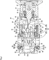
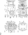
- Figs. 1 to 3D show a speed reduction device G1 (power transmission device) according to an example of an embodiment of the present invention in various directions and cross-sections.
- Fig. 3A is not a rear view when viewed from a rear surface in a state where up and down directions are maintained with respect to Fig. 2 but a rear view (reversed in the up and down directions) when viewed from a rear surface in a state where left and right directions are maintained with respect to Fig. 2 .
- the speed reduction device G1 When the speed reduction device G1 is schematically described, the speed reduction device G1 is used to be connected via a motor (not shown) and a connection casing 12.
- the speed reduction device G1 includes a gear speed reduction mechanism 14 and a casing 16 which accommodates the gear speed reduction mechanism 14.
- the gear speed reduction mechanism 14 includes an input shaft 18, a hypoid pinion 20 (input pinion) provided on the input shaft 18, an intermediate shaft 22A and an output shaft 22B which are rotary shafts 22 other than the input shaft 18, and a hypoid gear 24A (orthogonal gear), an intermediate gear 24B, and an output gear 24C which are gears 24 (other than the input pinion) which are incorporated on the rotary shaft 22.
- the casing 16 is made of a resin.
- the casing 16 includes a casing body 30, which includes an incorporating opening 26 for incorporating the gear 24 (hypoid gear 24A, intermediate gear 24B, and output gear 24C), and a cover 32 which closes the incorporating opening 26.
- the casing body 30 further includes an input side opening 34 with the opening being a size that the hypoid pinion 20 (input pinion) can be inserted but the gear 24 (hypoid gear 24A, intermediate gear 24B, and output gear 24C) cannot be inserted.
- the rotary shaft 22 (intermediate shaft 22A and output shaft 22B) is supported by first bearing supports 36 and 37 and second bearing supports 38 and 39 which are formed in the casing body 30. However, the bearing supports of the rotary shaft 22 are not formed on the cover 32.
- connection casing 12 (an input shaft support member which is also used as a motor connection member) is provided between the motor and the speed reduction device G1.
- the input shaft 18 of the speed reduction device G1 is supported on the connection casing 12 via bearings 41 and 42.
- the connection casing 12 may not be necessary.
- a motor shaft of the motor is also used as the input shaft of the speed reduction device, an input pinion is formed on the tip of the motor shaft, and the input pinion of the tip of the motor shaft may be inserted into the casing of the speed reduction device.
- the input shaft may be supported by a bearing which is disposed in the input side opening.
- the input side opening has the size which does not allow the insertion of the gears other than the input shaft.
- the hypoid pinion 20 (input pinion) is formed on the input shaft 18.
- the hypoid pinion 20 is engaged with the hypoid gear 24A which is incorporated to the intermediate shaft 22A.
- the intermediate gear 24B is formed on the intermediate shaft 22A by directly cutting the intermediate gear 24B into the intermediate shaft 22A.
- the intermediate gear 24B is engaged with the output gear 24C which is incorporated to the output shaft 22B.
- all power transmission members (input shaft 18, hypoid pinion 20, rotary shaft 22, and gear 24) other than the casing 16 are formed of metal. That is, in a power transmission system, the configuration and the material are similar as those of the related art.
- the casing 16 of the speed reduction device G1 is configured of the casing body 30 and the cover 32.
- a configuration of the casing body 30 will be described in detail.
- the overall shape of the casing body 30 is an approximately rectangular parallelepiped shape, and the casing body includes the input side opening 34, the incorporating opening 26, the first bearing supports 36 and 37, and the second bearing supports 38 and 39.
- the input side opening 34 of the casing body 30 has the size that the hypoid pinion 20 can be inserted but the gear 24 (hypoid gear 24A, intermediate gear 24B, and output gear 24C) cannot be inserted, that is, has a minimum size required to insert the hypoid pinion 20.
- the hypoid pinion 20 is inserted into the casing body 30 from the input side opening 34 and is engaged with the hypoid gear 24A in the casing body 30.
- the input side opening 34 is formed at a position which is offset by ⁇ 1 from the center of a side surface of the casing body 30.
- a quadrilateral tubular portion 46 for connecting the connection casing 12 is formed to be protruded on a surface 30a (a surface of an input side of the casing body 30) on which the input side opening 34 is formed.
- a ring-like stiffened member 48 made of metal is positioned on a corner of an inner circumference of the tubular portion 46. Accordingly, strength and rigidity of the surface 30a, on which the input side opening 34 of the casing body 30 is formed, are increased.
- the incorporating opening 26 of the casing body 30 is formed on a surface 30b of a side opposite to the motor. That is, the input side opening 34 and the incorporating opening 26 are provided on opposite surfaces 30a and 30b of the casing body 30 respectively. Since the size of the gear 24 (hypoid gear 24A, intermediate gear 24B, and output gear 24C) other than the hypoid pinion 20 is larger than that of the input side opening 34, all the gears are inserted through the incorporating opening 26.
- the incorporating opening 26 is not a simple quadrilateral in shape, and includes a portion 26a in which an opening height (an opening width in a direction perpendicular to the output shaft 22B) h1 is larger than an outer diameter d2 of the output gear 24C incorporated to the output shaft 22B and a portion 26b in which an opening height h2 is smaller than the outer diameter d2.
- the opening height of the incorporating opening 26 means a size in a direction perpendicular to the axial direction of the output shaft 22B of the incorporating opening 26.
- the incorporating opening 26 includes the portion 26a in which the opening height h1 is larger than the outer diameter d2 of the output gear 24C and the output shaft 22B can be incorporated, and the portion 26b in which the opening height h2 is smaller than the outer diameter d2 of the output gear 24C and the output shaft 22B cannot be incorporated.
- a closed quadrilateral (ring-like) stiffened member 61 made of metal is also disposed around the incorporating opening 26, and thus, strength and rigidity in the vicinity of the incorporating opening 26 of the casing body 30 are further increased.
- a recess is formed in the inner side of the incorporating opening 26 of the casing body 30, and the stiffened member 61 is disposed in the recess and is interposed between the cover 32 and the recess.
- the casing body 30 further includes the first bearing supports 36 and 37 for supporting the intermediate shaft 22A and the second bearing supports 38 and 39 which support the output shaft 22B.
- the first bearing supports 36 and 37 and the second bearing supports 38 and 39 are formed on surfaces 30c and 30d which intersect (perpendicular in this example) the surfaces 30a and 30b (opposite surfaces of the casing body 30) on which the input side opening 34 and the incorporating opening 26 are provided.
- First openings 50 and 51 are formed on the first bearing supports 36 and 37 which support the intermediate shaft 22A.
- the inner diameter of the first opening 50 of the first bearing support 36 close to the hypoid gear 24A is D4
- the inner diameter of the first opening 51 of the first bearing support 37 far from the hypoid gear 24A is D5 which is smaller than D4 (D4 > D5).
- First bearings 60 and 62 are disposed in the first inner openings 50A and 51A respectively.
- First retaining rings 52 and 53 are fit to ends in the radial direction of the first inner openings 50A and 51A and lock the first bearings 60 and 62.
- Caps 54 and 55 are covered on the first outer openings 50B and 51B respectively.
- the intermediate shaft 22A can be incorporated into the casing 16 from the first opening 50 of the first bearing support 36 (close to the hypoid gear 24A) or the first opening 51 of the opposite first bearing support 37 from the outside of the casing body 30.
- the reason why the left and the right of the intermediate shaft 22A are different from each other on the paper surface of Fig. 1 is because the right side on the paper surface is shown in a developed cross-section.
- the first bearings 60 and 62 may be the same as each other, and on the contrary to the embodiment, D4 ⁇ D5 may be satisfied.
- the second bearing supports 38 and 39 which support the output shaft 22B also includes an approximately similar configuration to the first bearing supports 36 and 37. That is, also in the second bearing supports 38 and 39, second openings 56 and 57 (second inner openings 56A and 57A and second outer rings 56B and 57B) are formed.
- the second openings 56 and 57 of the second bearing supports 38 and 39 include an inner diameter D7 which is the same as the both ends of the output shaft 22B.
- Output shaft bearings 64 and 66 are fitted to the second inner openings 56A and 57A.
- Second retaining rings 58 and 59 are fitted to the ends in the radial direction of the second inner openings 56A and 57A and lock the output shaft bearings 64 and 66.
- the output shaft 22B protrudes outside the casing body 30, oil seals 70 and 71 are disposed on the second outer rings 56B and 57B. Accordingly, sealing between the output shaft 22B and the casing body 30 is performed. Also in the second bearing supports 38 and 39, since the inner diameter D7 of the second openings 56 and 57 is larger than a maximum outer diameter d8 of the output shaft 22B, the output shaft 22B can be incorporated into the casing 16 from the second opening 56 of the second bearing support 38 (close to the output gear 24C) or the second opening 57 of the opposite second bearing support 39 from the outside of the casing body 30.
- the thickness of the casing body 30 at the surface perpendicular to the output shaft 22B is not the same at each position (position of Fig. 2C and position of Fig. 3C ) in the axial direction.
- the same thicknesses m1 and m11 are maintained from the incorporating opening 26, and the thickness is thickened to correspond to the outer diameter d3 of the hypoid gear 24A only at the motor side.
- the thickness m1 of the casing body 30 of the side (the lower side in Fig.
- the thicknesses m3 and m4 of the side (the upper side in Fig. 3A to 3D ), to which the input shaft 18 (or the connection casing 12 which supports the input shaft 18) is shifted (by the ⁇ 1) from the center of the casing 16 in the axial direction of the output shaft 22B, are formed to be thicker than the thicknesses m13 and m14 of the counter-shift side.
- the cover 32 of the casing 16 which closes the incorporating opening 26 is quadrilateral which is the same shape as the side surface shape of the casing body 30.
- the cover 32 is fixed to the side surface 30b of the side opposite to the motor of the casing body 30 by four bolts 80 (refer to Figs. 2D and 3D ), and thus, the incorporating opening 26 is closed.
- the bearing support which supports the rotary shaft 22 is not provided on the cover 32.
- the cover 32 closes the incorporating opening 26, and thus, a closed space, in which lubricant is enclosed in the casing body 30, is formed, and the periphery of the incorporating opening 26 of the side surface 30b of the casing body 30 is stiffened so as not to be deformed.
- a recess 32a is formed in the cover 32, and thus, a portion of the output gear 24C enters the recess 32a (refer to Figs. 1 and 3C ).
- the casing body 30 and the cover 32 which configure the casing 16 are prepared.
- the input side opening 34, the incorporating opening 26 to which the gear 24 is incorporated, and the first bearing supports 36 and 37 and the second bearing supports 38 and 39 which support the rotary shaft 22 are formed in the casing body 30.
- the hypoid gear 24A is put into the casing body 30 from the incorporating opening 26, and is positioned with respect to the first opening 50 (first inner opening 50A and first outer opening 50B) of the first bearing support 36 formed in the casing body 30 (also possible in the first bearing support 37 side).
- the intermediate shaft 22A (to which the intermediate gear 24B is integrally formed) is inserted from the first opening 50 of the first bearing support 36, and the hypoid gear 24A, which is positioned to the first opening 50 in advance, is assembled to the inserted intermediate shaft 22A (also possible from the first bearing support 37 side).
- first bearings 60 and 62 are disposed between the intermediate shaft 22A and the first inner openings 50A and 51A of the first bearing supports 36 and 37, and the intermediate shaft 22A is bearing-supported in the casing body 30.
- first retaining rings 52 and 53 are fitted, and the caps 54 and 55 are covered on the first outer openings 50B and 51B.
- the output gear 24C and the output shaft 22B are assembled. That is, first, the output gear 24C is put into the casing body 30 from the portion 26a in which the opening height h1 of the incorporating opening 26 is formed to be larger than the outer diameter d2 of the output gear 24C, and is positioned with respect to the second opening 57 of the second bearing support 39 formed in the casing 16 (also possible in the second bearing support 38 side) . Sequentially, the output shaft 22B is inserted from the second opening 57 of the second bearing support 39, and the output gear 24C, which is positioned to the second opening 57 in advance, is assembled to the inserted output shaft 22B (also possible from the second bearing support 38 side).
- the output shaft bearings 64 and 66 are disposed between the output shaft 22B and the second inner openings 56A and 57A of the second openings 56 and 57, and the output shaft 22B is bearing-supported in the casing body 30.
- the second retaining rings 58 and 59 are fitted, and the oil seals 70 and 71 are covered on the second outer opening 56B and 57B.
- the cover 32 is placed on the incorporating opening 26 and is closed by bolts 80, and finally, the hypoid pinion 20 supported to the connection casing 12 is inserted into the input side opening 34 and is engaged with the hypoid gear 24A which is incorporated in advance. Moreover, the insertion of the hypoid pinion 20 and the engagement between the hypoid pinion and the hypoid gear 24 may be performed before or after the incorporation of the hypoid gear 24A.
- the hypoid pinion 20 is inserted from the input side opening 34, the hypoid gear 24A and output gear 24C are incorporated from the incorporating opening 26, and the rotary shaft 22 (intermediate shaft 22A and output shaft 22B) can be incorporated from the first openings 50 and 51 of the first bearing supports 36 and 37 and the second openings 56 and 57 of the second bearing supports 38 and 39.
- the input side opening 34 is the opening having the minimum size through which the hypoid pinion 20 can be inserted and the first bearing supports 36 and 37 and the second bearing supports 38 and 39 are formed only on the casing body 30 side in which rigidity is easily secured, the intermediate shaft 22A and the output shaft 22B can be supported with high strength and rigidity, and rotation can be stably maintained.
- the input pinion is the hypoidpinion 20 (orthogonal pinion)
- the input side opening 34 and the incorporating opening 26 are provided on the opposite surfaces 30a and 30b of the casing body 30 respectively
- the first bearing supports 36 and 37 and the second bearing supports 38 and 39 are formed on the surfaces 30c and 30d which intersect (perpendicular in this example) the surfaces 30a and 30b on which the input side opening 34 and the incorporating opening 26 are provided. Accordingly, since the plurality of openings are not lined up on the same surface, strength or rigidity of the casing body 30 can be highly maintained.
- stiffened member 61 made of metal is disposed in the incorporating opening 26, although the relatively large incorporating opening 26 is formed, strength or rigidity in the vicinity of the incorporating opening 26 can be highly maintained.
- the tubular portion 46 for connecting the connection casing 12 is formed in the input side of the casing body 30, and the stiffened member 48 made of metal is disposed in the inner circumference of the tubular portion 46.
- the orthogonal engagement mechanism in which the hypoid pinion 20 and the hypoid gear 24A are engaged with each other at shaft centers offset to each other, is adopted in the input side of the gear speed reduction mechanism 14, support rigidity of the hypoid pinion 20 and the hypoid gear 24A is needed to be highly maintained.
- strength and rigidity of the input side can be highly maintained.
- the incorporating opening 26 includes the portion 26a in which the opening height h1 is larger than the outer diameter d2 of the output gear 24C incorporated to the output shaft 22B and the portion 26b in which the opening height h2 is smaller than the outer diameter d2, the overall opening area of the incorporating opening 26 can be maintained to be smaller while the output gear 24C can be incorporated. Therefore, with the decrease of the opening area, strength and rigidity of the casing body 30, particularly, the strength and the rigidity in the vicinity of the incorporating opening 26 can be increased.
- the recess 32a is formed in the cover 32 and the cover is configured so that a portion of the output gear 24C enters the recess 32a, the overall strength of the cover 32 can be highly maintained while an increase in the size in the longitudinal direction (axial direction of the input shaft 18) of the speed reduction device G1 is avoided.
- the hypoid pinion 20 (orthogonal pinion) is adopted as the input pinion.
- the gear speed reduction mechanism of the power transmission device according to the present invention includes the configuration of the input pinion, and particularly, the present invention is not limited to the configuration. That is, for example, the input pinion may be a spur pinion or a helical pinion.
- the stiffened member 61 made of metal is disposed in the incorporating opening 26, the tubular portion 46 for connecting the connection casing 12 which is a motor connection member is formed in the input side of the casing body 30, the stiffened member 48 made of metal is disposed in the inner circumference of the tubular portion 46, and thus, the strength and the rigidity are further increased.
- the stiffened member is disposed in the periphery of the bearing disposition portion, and thus, the stiffening effect may be increased.
- the incorporating opening 26 is formed in the shape which includes the portion 26a in which the opening height h1 is larger than the outer diameter d2 of the output gear 24C incorporated to the output shaft 22B in the gear 24 incorporated to the rotary shaft 22, and the portion 26b in which the opening height h2 is smaller than the outer diameter d2 so that the incorporating opening 26 has an approximately minimum opening area.
- this configuration is also not absolutely necessary.
- the recess 32a is formed in the cover 32 and a portion of the gear 24 (output gear 24C) enters the recess 32a.
- the cover 32 may be a simple flat plate.
Landscapes
- Engineering & Computer Science (AREA)
- General Engineering & Computer Science (AREA)
- Mechanical Engineering (AREA)
- General Details Of Gearings (AREA)
- Gear Transmission (AREA)
Claims (6)
- Leistungsübertragungsvorrichtung (G1), die Folgendes aufweist:einen Zahnraddrehzahluntersetzungsmechanismus (14), der eine Eingangswelle (18), ein Eingangsritzel (20), welches an der Eingangswelle (18) vorgesehen ist, eine sich drehende Welle bzw. Drehwelle (22), die eine andere ist als die Eingangswelle (18) und ein Zahnrad (24), aufweist, welches in der Drehwelle (22) verkörpert ist und in kämmendem Eingriff mit dem Eingangsritzel (20) ist; undein Gehäuse (16), welches den Zahnraddrehzahluntersetzungsmechanismus (14) aufnimmt,wobei das Gehäuse (16) aus Kunststoff gemacht ist und einen Gehäusekörper (30) aufweist, der eine Einführungsöffnung (26) aufweist, um das Zahnrad (24) einzuführen, und eine Abdeckung (32), welche die Einführungsöffnung (26) schließt,wobei der Gehäusekörper (30) eine Eingangsseitenöffnung (34) aufweist,wobei die Öffnung (34) größer bemessen ist als das Eingangsritzel (20),so dass das Eingangsritzel (20) eingeführt werden kann, jedoch kleiner als das Zahnrad (24), so dass das Zahnrad (24) nicht eingeführt werden kann,wobei die Drehwelle (22) durch einen Lagerträger (36, 37, 38, 39) getragen wird, der in dem Gehäusekörper (30) geformt ist, und wobei der Lagerträger (36, 37, 38, 39) der Drehwelle (22) nicht an der Abdeckung (32) geformt ist, undwobei das Eingangsritzel (20) ein Hypoidritzel ist,dadurch gekennzeichnet, dassdie Eingangsseitenöffnung (34) und die Einführungsöffnung (26) jeweils auf gegenüberliegenden Flächen des Gehäusekörpers (30) vorgesehen sind, undwobei der Lagerträger (36, 37, 38, 39) an einer Oberfläche (30c, 30d) geformt ist, welcher eine Oberfläche (30a) schneidet, an der die Eingangsseitenöffnung (34) vorgesehen ist und eine Oberfläche (30b), an der die Einführungsöffnung (26) vorgesehen ist.
- Leistungsübertragungsvorrichtung nach Anspruch 1, wobei ein versteiftes Glied (61) aus Metall in der Einführungsöffnung (26) angeordnet ist.
- Leistungsübertragungsvorrichtung nach Anspruch 1, wobei ein Rohrteil (46) zum Verbinden mit einem Motors oder einem Motorverbindungsglied (12) in einer Eingangsseite des Gehäusekörpers (30) geformt ist und wobei ein versteiftes Glied (48), das aus Metall gemacht ist, in einem Innenumfang des Rohrteils (46) angeordnet ist.
- Leistungsübertragungsvorrichtung nach Anspruch 1, wobei die Einführungsöffnung (26) einen Teil (26a) aufweist, wobei eine Öffnungshöhe (h1) größer ist als ein Außendurchmesser (d2) eines Ausgangszahnrades (24C), welches in einer Ausgangswelle (22B) der Zahnräder (24) verkörpert ist, die an der Drehwelle (22) verkörpert sind, und einen Teil (26b), wobei eine Öffnungshöhe (h2) kleiner ist als der Außendurchmesser (d2) des Ausgangszahnrades (24C).
- Leistungsübertragungsvorrichtung nach Anspruch 1, wobei eine Ausnehmung (32a) in der Abdeckung (32) geformt ist, und wobei ein Teil des Zahnrades (24) in die Ausnehmung (32a) eintritt.
- Herstellungsverfahren für eine Leistungsübertragungsvorrichtung (G1) nach einem der vorhergehenden Ansprüche, wobei das Verfahren Folgendes aufweist:Vorbereiten des Gehäusekörpers (30), der die Eingangsseitenöffnung (34) aufweist, durch welche das Eingangsritzel (20) eingeführt wird, weiter die Einführungsöffnung (26), durch welche das Zahnrad (24) eingeführt wird und den Lagerträger (36, 37, 38, 39), der die Drehwelle (22) trägt, und die Abdeckung (32), welche die Einführungsöffnung (26) schließt, und zwar als das Gehäuse (16);Anordnen des Zahnrades (24) von der Einführungsöffnung (26) in den Gehäusekörper (30) und Positionieren des Zahnrades (24) an einer Öffnung (50, 51, 56, 57) des Lagerträgers (36, 37, 38, 39), der in dem Gehäusekörper (30) geformt ist;Einführen der Drehwelle (22) von der Öffnung (50, 51, 56, 57) des Lagerträgers (36, 37, 38, 39) und Montieren des Zahnrades (24), welches in der Öffnung (50, 51, 56, 57) des Lagerträgers (36, 37, 38, 39) zuvor positioniert ist, an der eingeführten Drehwelle (22):Anordnen eines Lagers (60, 62, 64, 66) zwischen der Drehwelle (22) und der Öffnung (50, 51, 56, 57) des Lagerträgers (36, 37, 38, 39) und Lagern der Drehwelle (22) mit dem Lager (60, 62, 64, 66) in dem Gehäusekörper (30);Schließen der Einführungsöffnung (26) durch die Abdeckung (32); undEinführen des Eingangsritzels (20) in die Eingangsseitenöffnung (34) und In-Eingriff-Bringen des Eingangsritzels (20) mit dem Zahnrad (24), welches zuvor eingeführt wurde.
Applications Claiming Priority (1)
| Application Number | Priority Date | Filing Date | Title |
|---|---|---|---|
| JP2012237320A JP5844712B2 (ja) | 2012-10-26 | 2012-10-26 | 動力伝達装置およびその製造方法 |
Publications (3)
| Publication Number | Publication Date |
|---|---|
| EP2743545A2 EP2743545A2 (de) | 2014-06-18 |
| EP2743545A3 EP2743545A3 (de) | 2014-11-26 |
| EP2743545B1 true EP2743545B1 (de) | 2020-01-15 |
Family
ID=48948206
Family Applications (1)
| Application Number | Title | Priority Date | Filing Date |
|---|---|---|---|
| EP13020073.6A Active EP2743545B1 (de) | 2012-10-26 | 2013-08-02 | Kraftübertragungsvorrichtung und verfahren zu ihrer herstellung |
Country Status (4)
| Country | Link |
|---|---|
| US (1) | US9377098B2 (de) |
| EP (1) | EP2743545B1 (de) |
| JP (1) | JP5844712B2 (de) |
| CN (1) | CN103791067B (de) |
Families Citing this family (3)
| Publication number | Priority date | Publication date | Assignee | Title |
|---|---|---|---|---|
| JP6599257B2 (ja) * | 2016-01-29 | 2019-10-30 | 住友重機械工業株式会社 | ケーシング |
| JP2019132407A (ja) * | 2018-02-02 | 2019-08-08 | 住友重機械ギヤボックス株式会社 | 動力伝達装置 |
| JP7374791B2 (ja) * | 2020-01-31 | 2023-11-07 | マブチモーター株式会社 | 減速機およびギアドモータ |
Family Cites Families (31)
| Publication number | Priority date | Publication date | Assignee | Title |
|---|---|---|---|---|
| US2604795A (en) * | 1950-03-08 | 1952-07-29 | Milwaukee Electric Tool Corp | Angular drive |
| US2785587A (en) * | 1955-03-28 | 1957-03-19 | Clifton D Lowe | Differential transmission |
| DE1172124B (de) * | 1962-01-19 | 1964-06-11 | Daimler Benz Ag | Anordnung des Ausgleichgetriebes im Achs-getriebegehaeuse fuer Kraftfahrzeuge |
| JP2521403Y2 (ja) * | 1991-06-04 | 1996-12-25 | 株式会社ミツバ | ウオーム減速機付小型モータ |
| US5330394A (en) * | 1991-07-09 | 1994-07-19 | Hydro-Gear Limited Partnership | Rider transaxle having improved hydrostatic transmission |
| US5287770A (en) * | 1992-11-25 | 1994-02-22 | Schiller-Pfeiffer, Inc. | Die cast transmission housing for rototiller |
| JP3336141B2 (ja) * | 1995-01-27 | 2002-10-21 | アスモ株式会社 | 移動体の位置検出装置 |
| JP2971870B1 (ja) * | 1998-09-29 | 1999-11-08 | 川崎重工業株式会社 | ベルトコンバータのカバー構造 |
| FR2798184B1 (fr) * | 1999-09-07 | 2001-11-23 | Guy Fontanille | Carter de dispositif de renvoi d'angle de moteur de propulsion pour bateau |
| DE10013785A1 (de) * | 2000-03-20 | 2001-10-18 | Sew Eurodrive Gmbh & Co | Getriebebaukasten |
| US6628026B2 (en) | 2000-03-30 | 2003-09-30 | Asmo Co., Ltd. | Geared motor including ribbed gear housing |
| JP3705425B2 (ja) | 2000-03-30 | 2005-10-12 | アスモ株式会社 | ギヤードモータ |
| JP2002327805A (ja) * | 2001-05-01 | 2002-11-15 | Sankyo Seiki Mfg Co Ltd | 歯車付モータ |
| JP2003235302A (ja) * | 2002-02-21 | 2003-08-26 | Honda Motor Co Ltd | 管理機 |
| TWI235636B (en) * | 2002-02-21 | 2005-07-11 | Honda Motor Co Ltd | Cultivator |
| JP3782748B2 (ja) * | 2002-03-29 | 2006-06-07 | 株式会社ジェイテクト | 車両のステアリング装置 |
| JP2004301234A (ja) * | 2003-03-31 | 2004-10-28 | Sumitomo Heavy Ind Ltd | 直交軸歯車減速機 |
| CN104098891A (zh) * | 2005-05-12 | 2014-10-15 | 株式会社捷太格特 | 聚酰胺树脂组合物 |
| US20070044587A1 (en) * | 2005-08-29 | 2007-03-01 | Shine Far Metal Industry Co., Ltd. | Driving device for differential |
| TW200722657A (en) * | 2005-11-10 | 2007-06-16 | Sumitomo Heavy Industries | Power transmission mechanism, parts assembly comprising the power transmission mechanism, and fabrication method of the power transmission apparatus |
| JP2007327521A (ja) * | 2006-06-06 | 2007-12-20 | Sumitomo Heavy Ind Ltd | ハイポイド減速機 |
| JP5006691B2 (ja) * | 2007-04-27 | 2012-08-22 | 住友重機械工業株式会社 | ハイポイドギヤモータ及びその製造方法 |
| JP5428258B2 (ja) * | 2008-09-11 | 2014-02-26 | アイシン精機株式会社 | 車両用パワーシート装置 |
| JP5130177B2 (ja) * | 2008-09-29 | 2013-01-30 | 住友重機械工業株式会社 | 減速装置 |
| JP2010091013A (ja) * | 2008-10-08 | 2010-04-22 | Sumitomo Heavy Ind Ltd | 減速装置の軸の支持構造 |
| WO2010081523A1 (de) * | 2009-01-13 | 2010-07-22 | Sew-Eurodrive Gmbh & Co. Kg | Getriebegehäuse |
| DE102009005344A1 (de) * | 2009-01-16 | 2010-08-05 | Sew-Eurodrive Gmbh & Co. Kg | Getriebemotor |
| JP5267372B2 (ja) | 2009-07-31 | 2013-08-21 | アイシン精機株式会社 | パワーシートの減速装置 |
| JP5374395B2 (ja) | 2010-01-15 | 2013-12-25 | 住友重機械工業株式会社 | オイルシール |
| JP5425700B2 (ja) * | 2010-04-30 | 2014-02-26 | 住友重機械工業株式会社 | 風力発電設備の減速装置及びその据え付け方法 |
| JP5615745B2 (ja) * | 2011-03-16 | 2014-10-29 | 住友重機械工業株式会社 | 減速装置、及び減速装置のシリーズ |
-
2012
- 2012-10-26 JP JP2012237320A patent/JP5844712B2/ja not_active Expired - Fee Related
-
2013
- 2013-07-08 CN CN201310284482.3A patent/CN103791067B/zh not_active Expired - Fee Related
- 2013-07-26 US US13/951,863 patent/US9377098B2/en not_active Expired - Fee Related
- 2013-08-02 EP EP13020073.6A patent/EP2743545B1/de active Active
Non-Patent Citations (1)
| Title |
|---|
| None * |
Also Published As
| Publication number | Publication date |
|---|---|
| EP2743545A2 (de) | 2014-06-18 |
| CN103791067B (zh) | 2017-06-13 |
| JP2014085008A (ja) | 2014-05-12 |
| CN103791067A (zh) | 2014-05-14 |
| US9377098B2 (en) | 2016-06-28 |
| JP5844712B2 (ja) | 2016-01-20 |
| US20140116171A1 (en) | 2014-05-01 |
| EP2743545A3 (de) | 2014-11-26 |
Similar Documents
| Publication | Publication Date | Title |
|---|---|---|
| EP2684723B1 (de) | Antriebsvorrichtung für ein elektrofahrzeug | |
| EP2684722B1 (de) | Antriebsvorrichtung für ein elektrofahrzeug | |
| EP2685610B1 (de) | Antriebsvorrichtung für ein elektrofahrzeug | |
| US6481306B2 (en) | Geared motor having seal member for restraining intrusion of water or the like | |
| US9362804B2 (en) | Drive device for electric vehicle | |
| CN105762977B (zh) | 电机驱动组件及其齿轮箱 | |
| EP2685609B1 (de) | Antriebsvorrichtung für ein elektrofahrzeug | |
| EP2476602A2 (de) | Lenksystem | |
| WO2019194222A1 (ja) | 減速機構および減速機構付モータ | |
| CN111213305A (zh) | 驱动装置 | |
| EP2103843A1 (de) | Motor mit untersetzungsgetriebe | |
| US20250120380A1 (en) | Electric fishing reel | |
| US20230272840A1 (en) | Transmission housing, gearbox and wheeled vehicle provided with such a gearbox | |
| EP3072726B1 (de) | Planetengetriebeeinheit | |
| EP2743545A2 (de) | Kraftübertragungsvorrichtung und Verfahren zu ihrer Herstellung | |
| CN111082592B (zh) | 一种电机以及包含该电机的驱动器 | |
| US20090044649A1 (en) | Spur Gear Transmission | |
| JP2021121741A (ja) | 減速機およびギアドモータ | |
| JP2006304558A (ja) | モータ組込みハイポサイクロイド減速機 | |
| CN211266660U (zh) | 一种电机以及包含该电机的驱动器 | |
| CN118589753A (zh) | 驱动装置及电动泵 | |
| CN215622243U (zh) | 方向机和全地形车 | |
| KR101939470B1 (ko) | 차량의 전자 브레이크 모터 | |
| JP4155012B2 (ja) | ドライブユニットケース用キャップ、及びドライブユニットケースのモータ取付構造 | |
| JP2025076646A (ja) | 減速機構付モータ |
Legal Events
| Date | Code | Title | Description |
|---|---|---|---|
| PUAI | Public reference made under article 153(3) epc to a published international application that has entered the european phase |
Free format text: ORIGINAL CODE: 0009012 |
|
| 17P | Request for examination filed |
Effective date: 20130802 |
|
| AK | Designated contracting states |
Kind code of ref document: A2 Designated state(s): AL AT BE BG CH CY CZ DE DK EE ES FI FR GB GR HR HU IE IS IT LI LT LU LV MC MK MT NL NO PL PT RO RS SE SI SK SM TR |
|
| AX | Request for extension of the european patent |
Extension state: BA ME |
|
| PUAL | Search report despatched |
Free format text: ORIGINAL CODE: 0009013 |
|
| AK | Designated contracting states |
Kind code of ref document: A3 Designated state(s): AL AT BE BG CH CY CZ DE DK EE ES FI FR GB GR HR HU IE IS IT LI LT LU LV MC MK MT NL NO PL PT RO RS SE SI SK SM TR |
|
| AX | Request for extension of the european patent |
Extension state: BA ME |
|
| RIC1 | Information provided on ipc code assigned before grant |
Ipc: F16H 57/032 20120101ALI20141022BHEP Ipc: F16H 57/02 20120101AFI20141022BHEP |
|
| R17P | Request for examination filed (corrected) |
Effective date: 20150526 |
|
| RBV | Designated contracting states (corrected) |
Designated state(s): AL AT BE BG CH CY CZ DE DK EE ES FI FR GB GR HR HU IE IS IT LI LT LU LV MC MK MT NL NO PL PT RO RS SE SI SK SM TR |
|
| 17Q | First examination report despatched |
Effective date: 20160615 |
|
| GRAP | Despatch of communication of intention to grant a patent |
Free format text: ORIGINAL CODE: EPIDOSNIGR1 |
|
| STAA | Information on the status of an ep patent application or granted ep patent |
Free format text: STATUS: GRANT OF PATENT IS INTENDED |
|
| INTG | Intention to grant announced |
Effective date: 20190925 |
|
| GRAS | Grant fee paid |
Free format text: ORIGINAL CODE: EPIDOSNIGR3 |
|
| GRAA | (expected) grant |
Free format text: ORIGINAL CODE: 0009210 |
|
| STAA | Information on the status of an ep patent application or granted ep patent |
Free format text: STATUS: THE PATENT HAS BEEN GRANTED |
|
| AK | Designated contracting states |
Kind code of ref document: B1 Designated state(s): AL AT BE BG CH CY CZ DE DK EE ES FI FR GB GR HR HU IE IS IT LI LT LU LV MC MK MT NL NO PL PT RO RS SE SI SK SM TR |
|
| REG | Reference to a national code |
Ref country code: GB Ref legal event code: FG4D Ref country code: CH Ref legal event code: EP |
|
| REG | Reference to a national code |
Ref country code: IE Ref legal event code: FG4D |
|
| REG | Reference to a national code |
Ref country code: DE Ref legal event code: R096 Ref document number: 602013065043 Country of ref document: DE |
|
| REG | Reference to a national code |
Ref country code: AT Ref legal event code: REF Ref document number: 1225430 Country of ref document: AT Kind code of ref document: T Effective date: 20200215 |
|
| REG | Reference to a national code |
Ref country code: NL Ref legal event code: MP Effective date: 20200115 |
|
| REG | Reference to a national code |
Ref country code: LT Ref legal event code: MG4D |
|
| PG25 | Lapsed in a contracting state [announced via postgrant information from national office to epo] |
Ref country code: FI Free format text: LAPSE BECAUSE OF FAILURE TO SUBMIT A TRANSLATION OF THE DESCRIPTION OR TO PAY THE FEE WITHIN THE PRESCRIBED TIME-LIMIT Effective date: 20200115 Ref country code: NO Free format text: LAPSE BECAUSE OF FAILURE TO SUBMIT A TRANSLATION OF THE DESCRIPTION OR TO PAY THE FEE WITHIN THE PRESCRIBED TIME-LIMIT Effective date: 20200415 Ref country code: NL Free format text: LAPSE BECAUSE OF FAILURE TO SUBMIT A TRANSLATION OF THE DESCRIPTION OR TO PAY THE FEE WITHIN THE PRESCRIBED TIME-LIMIT Effective date: 20200115 Ref country code: PT Free format text: LAPSE BECAUSE OF FAILURE TO SUBMIT A TRANSLATION OF THE DESCRIPTION OR TO PAY THE FEE WITHIN THE PRESCRIBED TIME-LIMIT Effective date: 20200607 Ref country code: RS Free format text: LAPSE BECAUSE OF FAILURE TO SUBMIT A TRANSLATION OF THE DESCRIPTION OR TO PAY THE FEE WITHIN THE PRESCRIBED TIME-LIMIT Effective date: 20200115 |
|
| PG25 | Lapsed in a contracting state [announced via postgrant information from national office to epo] |
Ref country code: BG Free format text: LAPSE BECAUSE OF FAILURE TO SUBMIT A TRANSLATION OF THE DESCRIPTION OR TO PAY THE FEE WITHIN THE PRESCRIBED TIME-LIMIT Effective date: 20200415 Ref country code: GR Free format text: LAPSE BECAUSE OF FAILURE TO SUBMIT A TRANSLATION OF THE DESCRIPTION OR TO PAY THE FEE WITHIN THE PRESCRIBED TIME-LIMIT Effective date: 20200416 Ref country code: IS Free format text: LAPSE BECAUSE OF FAILURE TO SUBMIT A TRANSLATION OF THE DESCRIPTION OR TO PAY THE FEE WITHIN THE PRESCRIBED TIME-LIMIT Effective date: 20200515 Ref country code: HR Free format text: LAPSE BECAUSE OF FAILURE TO SUBMIT A TRANSLATION OF THE DESCRIPTION OR TO PAY THE FEE WITHIN THE PRESCRIBED TIME-LIMIT Effective date: 20200115 Ref country code: SE Free format text: LAPSE BECAUSE OF FAILURE TO SUBMIT A TRANSLATION OF THE DESCRIPTION OR TO PAY THE FEE WITHIN THE PRESCRIBED TIME-LIMIT Effective date: 20200115 Ref country code: LV Free format text: LAPSE BECAUSE OF FAILURE TO SUBMIT A TRANSLATION OF THE DESCRIPTION OR TO PAY THE FEE WITHIN THE PRESCRIBED TIME-LIMIT Effective date: 20200115 |
|
| REG | Reference to a national code |
Ref country code: DE Ref legal event code: R097 Ref document number: 602013065043 Country of ref document: DE |
|
| PG25 | Lapsed in a contracting state [announced via postgrant information from national office to epo] |
Ref country code: DK Free format text: LAPSE BECAUSE OF FAILURE TO SUBMIT A TRANSLATION OF THE DESCRIPTION OR TO PAY THE FEE WITHIN THE PRESCRIBED TIME-LIMIT Effective date: 20200115 Ref country code: LT Free format text: LAPSE BECAUSE OF FAILURE TO SUBMIT A TRANSLATION OF THE DESCRIPTION OR TO PAY THE FEE WITHIN THE PRESCRIBED TIME-LIMIT Effective date: 20200115 Ref country code: ES Free format text: LAPSE BECAUSE OF FAILURE TO SUBMIT A TRANSLATION OF THE DESCRIPTION OR TO PAY THE FEE WITHIN THE PRESCRIBED TIME-LIMIT Effective date: 20200115 Ref country code: SM Free format text: LAPSE BECAUSE OF FAILURE TO SUBMIT A TRANSLATION OF THE DESCRIPTION OR TO PAY THE FEE WITHIN THE PRESCRIBED TIME-LIMIT Effective date: 20200115 Ref country code: EE Free format text: LAPSE BECAUSE OF FAILURE TO SUBMIT A TRANSLATION OF THE DESCRIPTION OR TO PAY THE FEE WITHIN THE PRESCRIBED TIME-LIMIT Effective date: 20200115 Ref country code: CZ Free format text: LAPSE BECAUSE OF FAILURE TO SUBMIT A TRANSLATION OF THE DESCRIPTION OR TO PAY THE FEE WITHIN THE PRESCRIBED TIME-LIMIT Effective date: 20200115 Ref country code: SK Free format text: LAPSE BECAUSE OF FAILURE TO SUBMIT A TRANSLATION OF THE DESCRIPTION OR TO PAY THE FEE WITHIN THE PRESCRIBED TIME-LIMIT Effective date: 20200115 Ref country code: RO Free format text: LAPSE BECAUSE OF FAILURE TO SUBMIT A TRANSLATION OF THE DESCRIPTION OR TO PAY THE FEE WITHIN THE PRESCRIBED TIME-LIMIT Effective date: 20200115 |
|
| REG | Reference to a national code |
Ref country code: AT Ref legal event code: MK05 Ref document number: 1225430 Country of ref document: AT Kind code of ref document: T Effective date: 20200115 |
|
| PLBE | No opposition filed within time limit |
Free format text: ORIGINAL CODE: 0009261 |
|
| STAA | Information on the status of an ep patent application or granted ep patent |
Free format text: STATUS: NO OPPOSITION FILED WITHIN TIME LIMIT |
|
| 26N | No opposition filed |
Effective date: 20201016 |
|
| PG25 | Lapsed in a contracting state [announced via postgrant information from national office to epo] |
Ref country code: AT Free format text: LAPSE BECAUSE OF FAILURE TO SUBMIT A TRANSLATION OF THE DESCRIPTION OR TO PAY THE FEE WITHIN THE PRESCRIBED TIME-LIMIT Effective date: 20200115 |
|
| PG25 | Lapsed in a contracting state [announced via postgrant information from national office to epo] |
Ref country code: PL Free format text: LAPSE BECAUSE OF FAILURE TO SUBMIT A TRANSLATION OF THE DESCRIPTION OR TO PAY THE FEE WITHIN THE PRESCRIBED TIME-LIMIT Effective date: 20200115 Ref country code: SI Free format text: LAPSE BECAUSE OF FAILURE TO SUBMIT A TRANSLATION OF THE DESCRIPTION OR TO PAY THE FEE WITHIN THE PRESCRIBED TIME-LIMIT Effective date: 20200115 |
|
| PG25 | Lapsed in a contracting state [announced via postgrant information from national office to epo] |
Ref country code: MC Free format text: LAPSE BECAUSE OF FAILURE TO SUBMIT A TRANSLATION OF THE DESCRIPTION OR TO PAY THE FEE WITHIN THE PRESCRIBED TIME-LIMIT Effective date: 20200115 |
|
| REG | Reference to a national code |
Ref country code: CH Ref legal event code: PL |
|
| GBPC | Gb: european patent ceased through non-payment of renewal fee |
Effective date: 20200802 |
|
| PG25 | Lapsed in a contracting state [announced via postgrant information from national office to epo] |
Ref country code: LI Free format text: LAPSE BECAUSE OF NON-PAYMENT OF DUE FEES Effective date: 20200831 Ref country code: CH Free format text: LAPSE BECAUSE OF NON-PAYMENT OF DUE FEES Effective date: 20200831 Ref country code: LU Free format text: LAPSE BECAUSE OF NON-PAYMENT OF DUE FEES Effective date: 20200802 |
|
| REG | Reference to a national code |
Ref country code: BE Ref legal event code: MM Effective date: 20200831 |
|
| PG25 | Lapsed in a contracting state [announced via postgrant information from national office to epo] |
Ref country code: FR Free format text: LAPSE BECAUSE OF NON-PAYMENT OF DUE FEES Effective date: 20200831 |
|
| PG25 | Lapsed in a contracting state [announced via postgrant information from national office to epo] |
Ref country code: GB Free format text: LAPSE BECAUSE OF NON-PAYMENT OF DUE FEES Effective date: 20200802 Ref country code: IE Free format text: LAPSE BECAUSE OF NON-PAYMENT OF DUE FEES Effective date: 20200802 Ref country code: BE Free format text: LAPSE BECAUSE OF NON-PAYMENT OF DUE FEES Effective date: 20200831 |
|
| PGFP | Annual fee paid to national office [announced via postgrant information from national office to epo] |
Ref country code: IT Payment date: 20210712 Year of fee payment: 9 |
|
| PGFP | Annual fee paid to national office [announced via postgrant information from national office to epo] |
Ref country code: DE Payment date: 20210630 Year of fee payment: 9 |
|
| PG25 | Lapsed in a contracting state [announced via postgrant information from national office to epo] |
Ref country code: TR Free format text: LAPSE BECAUSE OF FAILURE TO SUBMIT A TRANSLATION OF THE DESCRIPTION OR TO PAY THE FEE WITHIN THE PRESCRIBED TIME-LIMIT Effective date: 20200115 Ref country code: MT Free format text: LAPSE BECAUSE OF FAILURE TO SUBMIT A TRANSLATION OF THE DESCRIPTION OR TO PAY THE FEE WITHIN THE PRESCRIBED TIME-LIMIT Effective date: 20200115 Ref country code: CY Free format text: LAPSE BECAUSE OF FAILURE TO SUBMIT A TRANSLATION OF THE DESCRIPTION OR TO PAY THE FEE WITHIN THE PRESCRIBED TIME-LIMIT Effective date: 20200115 |
|
| PG25 | Lapsed in a contracting state [announced via postgrant information from national office to epo] |
Ref country code: MK Free format text: LAPSE BECAUSE OF FAILURE TO SUBMIT A TRANSLATION OF THE DESCRIPTION OR TO PAY THE FEE WITHIN THE PRESCRIBED TIME-LIMIT Effective date: 20200115 Ref country code: AL Free format text: LAPSE BECAUSE OF FAILURE TO SUBMIT A TRANSLATION OF THE DESCRIPTION OR TO PAY THE FEE WITHIN THE PRESCRIBED TIME-LIMIT Effective date: 20200115 |
|
| REG | Reference to a national code |
Ref country code: DE Ref legal event code: R119 Ref document number: 602013065043 Country of ref document: DE |
|
| PG25 | Lapsed in a contracting state [announced via postgrant information from national office to epo] |
Ref country code: IT Free format text: LAPSE BECAUSE OF NON-PAYMENT OF DUE FEES Effective date: 20220802 Ref country code: DE Free format text: LAPSE BECAUSE OF NON-PAYMENT OF DUE FEES Effective date: 20230301 |