EP2728212B1 - Bearing device for turbocharger - Google Patents
Bearing device for turbocharger Download PDFInfo
- Publication number
- EP2728212B1 EP2728212B1 EP12803917.9A EP12803917A EP2728212B1 EP 2728212 B1 EP2728212 B1 EP 2728212B1 EP 12803917 A EP12803917 A EP 12803917A EP 2728212 B1 EP2728212 B1 EP 2728212B1
- Authority
- EP
- European Patent Office
- Prior art keywords
- bearing
- floating bush
- peripheral surface
- floating
- outer peripheral
- Prior art date
- Legal status (The legal status is an assumption and is not a legal conclusion. Google has not performed a legal analysis and makes no representation as to the accuracy of the status listed.)
- Active
Links
Images


Classifications
-
- F—MECHANICAL ENGINEERING; LIGHTING; HEATING; WEAPONS; BLASTING
- F02—COMBUSTION ENGINES; HOT-GAS OR COMBUSTION-PRODUCT ENGINE PLANTS
- F02M—SUPPLYING COMBUSTION ENGINES IN GENERAL WITH COMBUSTIBLE MIXTURES OR CONSTITUENTS THEREOF
- F02M55/00—Fuel-injection apparatus characterised by their fuel conduits or their venting means; Arrangements of conduits between fuel tank and pump F02M37/00
-
- F—MECHANICAL ENGINEERING; LIGHTING; HEATING; WEAPONS; BLASTING
- F01—MACHINES OR ENGINES IN GENERAL; ENGINE PLANTS IN GENERAL; STEAM ENGINES
- F01D—NON-POSITIVE DISPLACEMENT MACHINES OR ENGINES, e.g. STEAM TURBINES
- F01D25/00—Component parts, details, or accessories, not provided for in, or of interest apart from, other groups
- F01D25/16—Arrangement of bearings; Supporting or mounting bearings in casings
- F01D25/166—Sliding contact bearing
-
- F—MECHANICAL ENGINEERING; LIGHTING; HEATING; WEAPONS; BLASTING
- F01—MACHINES OR ENGINES IN GENERAL; ENGINE PLANTS IN GENERAL; STEAM ENGINES
- F01D—NON-POSITIVE DISPLACEMENT MACHINES OR ENGINES, e.g. STEAM TURBINES
- F01D25/00—Component parts, details, or accessories, not provided for in, or of interest apart from, other groups
- F01D25/18—Lubricating arrangements
- F01D25/22—Lubricating arrangements using working-fluid or other gaseous fluid as lubricant
-
- F—MECHANICAL ENGINEERING; LIGHTING; HEATING; WEAPONS; BLASTING
- F02—COMBUSTION ENGINES; HOT-GAS OR COMBUSTION-PRODUCT ENGINE PLANTS
- F02B—INTERNAL-COMBUSTION PISTON ENGINES; COMBUSTION ENGINES IN GENERAL
- F02B39/00—Component parts, details, or accessories relating to, driven charging or scavenging pumps, not provided for in groups F02B33/00 - F02B37/00
- F02B39/14—Lubrication of pumps; Safety measures therefor
-
- F—MECHANICAL ENGINEERING; LIGHTING; HEATING; WEAPONS; BLASTING
- F16—ENGINEERING ELEMENTS AND UNITS; GENERAL MEASURES FOR PRODUCING AND MAINTAINING EFFECTIVE FUNCTIONING OF MACHINES OR INSTALLATIONS; THERMAL INSULATION IN GENERAL
- F16C—SHAFTS; FLEXIBLE SHAFTS; ELEMENTS OR CRANKSHAFT MECHANISMS; ROTARY BODIES OTHER THAN GEARING ELEMENTS; BEARINGS
- F16C17/00—Sliding-contact bearings for exclusively rotary movement
- F16C17/12—Sliding-contact bearings for exclusively rotary movement characterised by features not related to the direction of the load
- F16C17/18—Sliding-contact bearings for exclusively rotary movement characterised by features not related to the direction of the load with floating brasses or brushing, rotatable at a reduced speed
-
- F—MECHANICAL ENGINEERING; LIGHTING; HEATING; WEAPONS; BLASTING
- F16—ENGINEERING ELEMENTS AND UNITS; GENERAL MEASURES FOR PRODUCING AND MAINTAINING EFFECTIVE FUNCTIONING OF MACHINES OR INSTALLATIONS; THERMAL INSULATION IN GENERAL
- F16C—SHAFTS; FLEXIBLE SHAFTS; ELEMENTS OR CRANKSHAFT MECHANISMS; ROTARY BODIES OTHER THAN GEARING ELEMENTS; BEARINGS
- F16C27/00—Elastic or yielding bearings or bearing supports, for exclusively rotary movement
- F16C27/02—Sliding-contact bearings
-
- F—MECHANICAL ENGINEERING; LIGHTING; HEATING; WEAPONS; BLASTING
- F05—INDEXING SCHEMES RELATING TO ENGINES OR PUMPS IN VARIOUS SUBCLASSES OF CLASSES F01-F04
- F05D—INDEXING SCHEME FOR ASPECTS RELATING TO NON-POSITIVE-DISPLACEMENT MACHINES OR ENGINES, GAS-TURBINES OR JET-PROPULSION PLANTS
- F05D2220/00—Application
- F05D2220/40—Application in turbochargers
-
- F—MECHANICAL ENGINEERING; LIGHTING; HEATING; WEAPONS; BLASTING
- F05—INDEXING SCHEMES RELATING TO ENGINES OR PUMPS IN VARIOUS SUBCLASSES OF CLASSES F01-F04
- F05D—INDEXING SCHEME FOR ASPECTS RELATING TO NON-POSITIVE-DISPLACEMENT MACHINES OR ENGINES, GAS-TURBINES OR JET-PROPULSION PLANTS
- F05D2240/00—Components
- F05D2240/50—Bearings
- F05D2240/54—Radial bearings
-
- F—MECHANICAL ENGINEERING; LIGHTING; HEATING; WEAPONS; BLASTING
- F05—INDEXING SCHEMES RELATING TO ENGINES OR PUMPS IN VARIOUS SUBCLASSES OF CLASSES F01-F04
- F05D—INDEXING SCHEME FOR ASPECTS RELATING TO NON-POSITIVE-DISPLACEMENT MACHINES OR ENGINES, GAS-TURBINES OR JET-PROPULSION PLANTS
- F05D2250/00—Geometry
- F05D2250/60—Structure; Surface texture
- F05D2250/61—Structure; Surface texture corrugated
-
- F—MECHANICAL ENGINEERING; LIGHTING; HEATING; WEAPONS; BLASTING
- F16—ENGINEERING ELEMENTS AND UNITS; GENERAL MEASURES FOR PRODUCING AND MAINTAINING EFFECTIVE FUNCTIONING OF MACHINES OR INSTALLATIONS; THERMAL INSULATION IN GENERAL
- F16C—SHAFTS; FLEXIBLE SHAFTS; ELEMENTS OR CRANKSHAFT MECHANISMS; ROTARY BODIES OTHER THAN GEARING ELEMENTS; BEARINGS
- F16C17/00—Sliding-contact bearings for exclusively rotary movement
- F16C17/02—Sliding-contact bearings for exclusively rotary movement for radial load only
-
- F—MECHANICAL ENGINEERING; LIGHTING; HEATING; WEAPONS; BLASTING
- F16—ENGINEERING ELEMENTS AND UNITS; GENERAL MEASURES FOR PRODUCING AND MAINTAINING EFFECTIVE FUNCTIONING OF MACHINES OR INSTALLATIONS; THERMAL INSULATION IN GENERAL
- F16C—SHAFTS; FLEXIBLE SHAFTS; ELEMENTS OR CRANKSHAFT MECHANISMS; ROTARY BODIES OTHER THAN GEARING ELEMENTS; BEARINGS
- F16C17/00—Sliding-contact bearings for exclusively rotary movement
- F16C17/26—Systems consisting of a plurality of sliding-contact bearings
-
- F—MECHANICAL ENGINEERING; LIGHTING; HEATING; WEAPONS; BLASTING
- F16—ENGINEERING ELEMENTS AND UNITS; GENERAL MEASURES FOR PRODUCING AND MAINTAINING EFFECTIVE FUNCTIONING OF MACHINES OR INSTALLATIONS; THERMAL INSULATION IN GENERAL
- F16C—SHAFTS; FLEXIBLE SHAFTS; ELEMENTS OR CRANKSHAFT MECHANISMS; ROTARY BODIES OTHER THAN GEARING ELEMENTS; BEARINGS
- F16C2202/00—Solid materials defined by their properties
- F16C2202/50—Lubricating properties
- F16C2202/54—Molybdenum disulfide
-
- F—MECHANICAL ENGINEERING; LIGHTING; HEATING; WEAPONS; BLASTING
- F16—ENGINEERING ELEMENTS AND UNITS; GENERAL MEASURES FOR PRODUCING AND MAINTAINING EFFECTIVE FUNCTIONING OF MACHINES OR INSTALLATIONS; THERMAL INSULATION IN GENERAL
- F16C—SHAFTS; FLEXIBLE SHAFTS; ELEMENTS OR CRANKSHAFT MECHANISMS; ROTARY BODIES OTHER THAN GEARING ELEMENTS; BEARINGS
- F16C2206/00—Materials with ceramics, cermets, hard carbon or similar non-metallic hard materials as main constituents
- F16C2206/02—Carbon based material
- F16C2206/04—Diamond like carbon [DLC]
-
- F—MECHANICAL ENGINEERING; LIGHTING; HEATING; WEAPONS; BLASTING
- F16—ENGINEERING ELEMENTS AND UNITS; GENERAL MEASURES FOR PRODUCING AND MAINTAINING EFFECTIVE FUNCTIONING OF MACHINES OR INSTALLATIONS; THERMAL INSULATION IN GENERAL
- F16C—SHAFTS; FLEXIBLE SHAFTS; ELEMENTS OR CRANKSHAFT MECHANISMS; ROTARY BODIES OTHER THAN GEARING ELEMENTS; BEARINGS
- F16C2240/00—Specified values or numerical ranges of parameters; Relations between them
- F16C2240/40—Linear dimensions, e.g. length, radius, thickness, gap
-
- F—MECHANICAL ENGINEERING; LIGHTING; HEATING; WEAPONS; BLASTING
- F16—ENGINEERING ELEMENTS AND UNITS; GENERAL MEASURES FOR PRODUCING AND MAINTAINING EFFECTIVE FUNCTIONING OF MACHINES OR INSTALLATIONS; THERMAL INSULATION IN GENERAL
- F16C—SHAFTS; FLEXIBLE SHAFTS; ELEMENTS OR CRANKSHAFT MECHANISMS; ROTARY BODIES OTHER THAN GEARING ELEMENTS; BEARINGS
- F16C2360/00—Engines or pumps
- F16C2360/23—Gas turbine engines
- F16C2360/24—Turbochargers
-
- F—MECHANICAL ENGINEERING; LIGHTING; HEATING; WEAPONS; BLASTING
- F16—ENGINEERING ELEMENTS AND UNITS; GENERAL MEASURES FOR PRODUCING AND MAINTAINING EFFECTIVE FUNCTIONING OF MACHINES OR INSTALLATIONS; THERMAL INSULATION IN GENERAL
- F16C—SHAFTS; FLEXIBLE SHAFTS; ELEMENTS OR CRANKSHAFT MECHANISMS; ROTARY BODIES OTHER THAN GEARING ELEMENTS; BEARINGS
- F16C33/00—Parts of bearings; Special methods for making bearings or parts thereof
- F16C33/02—Parts of sliding-contact bearings
- F16C33/04—Brasses; Bushes; Linings
- F16C33/043—Sliding surface consisting mainly of ceramics, cermets or hard carbon, e.g. diamond like carbon [DLC]
-
- F—MECHANICAL ENGINEERING; LIGHTING; HEATING; WEAPONS; BLASTING
- F16—ENGINEERING ELEMENTS AND UNITS; GENERAL MEASURES FOR PRODUCING AND MAINTAINING EFFECTIVE FUNCTIONING OF MACHINES OR INSTALLATIONS; THERMAL INSULATION IN GENERAL
- F16C—SHAFTS; FLEXIBLE SHAFTS; ELEMENTS OR CRANKSHAFT MECHANISMS; ROTARY BODIES OTHER THAN GEARING ELEMENTS; BEARINGS
- F16C33/00—Parts of bearings; Special methods for making bearings or parts thereof
- F16C33/02—Parts of sliding-contact bearings
- F16C33/04—Brasses; Bushes; Linings
- F16C33/06—Sliding surface mainly made of metal
- F16C33/10—Construction relative to lubrication
- F16C33/1025—Construction relative to lubrication with liquid, e.g. oil, as lubricant
- F16C33/106—Details of distribution or circulation inside the bearings, e.g. details of the bearing surfaces to affect flow or pressure of the liquid
- F16C33/1065—Grooves on a bearing surface for distributing or collecting the liquid
Definitions
- the present invention relates a floating bush bearing which is suitable for a rotary machine having a high-speed rotation shaft, such as a turbocharger.
- a floating bush bearing includes a floating bush rotatably provided in a space between a rotation shaft and a bearing housing.
- the floating bush bearing is configured so as to supply pressurized lubricating oil from the bearing housing to a space between an inner peripheral surface of the bearing housing and an outer peripheral surface of the floating bush and also to a space between an inner peripheral surface of the floating bush and the rotation shaft via an oil supply path provided in the floating bush in the radial direction.
- the floating bush bearing is configured to support the rotation shaft stably while suppressing its oscillation by a damping effect of the oil film of the lubricating oil formed in these spaces and also to prevent seizure.
- FIG.5 is a detailed view of a floating bush bearing for rotatably supporting a rotation shaft of a high-speed rotary machine such as a turbocharger.
- a turbocharger 0100 is formed by a pair of vane wheels 0102a and 0102b and a rotor shaft 0104 for integrally connecting the pair of vane wheels 0102a and 0102b.
- a floating bush bearing 0110 is formed by a bearing housing 0112 and a floating bush 0114 placed between the bearing housing 0112 and the rotor shaft 0104. The floating bush 0114 rotatably supports the rotor shaft 0104.
- Oil passages 0116 and 0118 are provided in the bearing housing 0112 and the floating bush 0114, respectively.
- the lubricating oil is supplied from the bearing housing 0112 through the oil passages 0116 and 0118 to the space between the inner peripheral surface of the bearing housing 0112 and the outer peripheral surface of the floating bush 0114 and the space between the inner peripheral surface of the floating bush 0114 and the rotor shaft 0104.
- the floating bush 0114 is rotatably arranged and is configured to co-rotate with the rotor shaft 0104 at a speed lower than the rotor shaft 0104 due to sliding resistance against the rotor shaft 0104.
- the oil film composed of the lubricating oil is formed in these spaces so as to prevent seizure occurring at a sliding face in the spaces and damage (wear).
- JP 2009-156333 A Patent Document 1
- the width of the inner periphery of the floating bush on the compressor side, Lc is set smaller than the width of the inner periphery of the floating bush on the turbine side, Lt (Lc ⁇ Lt).
- a spring constant by an oil film on the floating bush bearing on the compressor side is smaller than a spring constant by an oil film on the floating bush bearing on the turbine side.
- a spiral groove is provided in at least one of an inner peripheral surface or an outer peripheral surface of a fully floating bearing and that, when the fully floating bearing is rotated, distribution of the pressure loaded on the inner or outer peripheral surface from fluid (lubricating oil) changes along the axial direction by the spiral groove formed in at least one of the inner peripheral surface or the outer peripheral surface. This change makes it difficult for the fully floating bearing to be in a stable state, thereby suppressing self-excited oscillation.
- US 4640630 A relates to a bearing assembly including floating bushes journaling a rotor shaft interposed between the rotor shaft and a housing assembly, the floating bushes each have an inner peripheral portion of a smaller length than an outer peripheral portion.
- JP S63-088318 A relates to a bearing device for a turbocharger with the features of the preamble of claim 1, wherein the outer peripheral surface of a floating bush is provided with a ring-shaped groove for feeding of lubricating oil sufficiently all over a bearing.
- US 7189005 B2 relates to a bearing system for a turbocharger having desired rotational dynamics of a three-piece bearing design.
- the width of the inner periphery of the floating bush on the compressor side, Lc is set smaller than the width of the inner periphery of the floating bush on the turbine side, Lt (Lc ⁇ Lt) so as to reduce the natural frequency caused by self-excited oscillation in the high frequency range decreases, thereby achieving noise reduction.
- the floating bush bearing on the compressor side and the floating bush bearing on the turbine side have different shapes and thus, the number of components increases. This results in increase in a management cost and a higher risk of misassembling.
- the spiral groove is provided in at least one of the inner and outer peripheral surfaces of the fully floating bearing. Therefore, it is a complicated work to form the groove and, in particular, the groove in the inner peripheral surface which has small inner diameter where the rotor shaft of the turbine rotor is fitted and the machining man hour increases. This results in higher component cost.
- an object of the present invention is to improve oscillation stability when a turbine rotor revolves at a high speed, reduce the number of parts, and facilitate processing and assemblability by configuring a first floating bush bearing disposed on a compressor housing side and a second floating bush bearing disposed on a turbine housing side to have substantially the same shape and reducing the width of the inner peripheral width Li relative to the outer peripheral width Lo of each of the first and second floating bushes at the same ratio.
- a bearing device for a turbocharger comprises:
- each of the first and second bushes is configured so that the inner bearing width Li is smaller than the outer bearing width Lo to reduce the co-rotation amount of the floating bush during the high-speed rotation of the rotor shaft and improve the oscillation stability during the high-speed rotation, thereby achieving the noise reduction effect.
- first and second bushes are configured so that the first and second bushes have the same ratio of the inner bearing width to the outer bearing width, viscosity resistance of the lubricating oil which occurs at the first and second bushes is the same, thereby achieving stable support of the rotor shaft.
- first and second floating bushes have the same configuration, it is possible to reduce the number of parts, and facilitate processing and assemblability. As a result, the risk of misassembling can be lowered and stable processing quality and cost reduction can be achieved.
- a ratio Li/Lo of the outer bearing width Lo to the inner bearing width Li is set to satisfy a range of Lx/Lo ⁇ Li/Lo ⁇ 0.5 where Lx is a minimum inner bearing width including a diameter ⁇ of the oil supply hole (oil supply path).
- the minimum width is set smaller than the diameter ⁇ of the oil supply hole, a tip of the oil supply path is removed to form an inclined surface of a cone shape. This causes the lubricating oil to flow directly in the axial direction of the rotor shaft from the oil supply hole ⁇ . This minimizes the damping effect of the lubricating oil on the floating bush bearing and the rotor shaft.
- the outer peripheral surface of the floating bush has a low friction treatment formed by a pair of edge grooves formed over the entire circumference of the outer peripheral surface on both sides of the oil supply hole of the outer peripheral surface in the bearing width direction, and a transverse groove is provided for each oil supply hole so that the pair of edge grooves communicate with the oil supply hole, the oil supply hole being provided at the center of the outer peripheral surface of the first and second floating bushes in the bearing width direction.
- the low friction treatment includes Diamond Like Carbon coating or molybdenum disulfide coating on the outer peripheral surface of the floating bush.
- the low friction treatment includes surface texture (dimples or micro recesses) formed on the outer peripheral surface of the floating bush.
- the low friction treatment includes a groove circumferentially arranged on the outer peripheral surface of the floating bush, the groove communicating with the oil supply hole.
- the lubricating oil fed from the lubricating oil path flows to a lower part of the floating bush via an edge groove, thereby filling a space between the floating bush and the bearing housing. As a result, the friction resistance at the start of rotation of can be suppressed.
- each of the first and second bushes by configuring each of the first and second bushes so that the inner bearing width is smaller than the outer bearing width, it is possible to maintain the co-rotation amount of each floating bush at an appropriate rotation speed with respect to the rotation speed of the rotor shaft during high-speed rotation of the rotor shaft, and improve the rotation oscillation stability so as to achieve the noise reduction effect.
- first and second floating bushes have the same configuration, it is possible to reduce the number of parts, and facilitate processing and assemblability. As a result, the risk of misassembling can be lowered and stable processing quality and cost reduction can be achieved.
- FIG.1 illustrates a floating bush bearing which rotatably supports a high-speed turbocharger according to an embodiment of the present invention.
- a turbocharger 1 is formed by an exhaust turbine 14 driven by exhaust gas of an internal combustion engine (hereinafter described as "engine"), a turbine housing 11 covering the exhaust turbine 14, a compressor impeller 15 for pressurizing intake air to the engine by a driving force of the exhaust turbine 14, a compressor housing 12 for covering the compressor impeller 15, a rotor shaft 16 for integrally connecting the exhaust turbine 14 and the compressor impeller 15, a bearing housing 15 interposed between the turbine housing 11 and the compressor housing 12 and rotatably supporting the rotor shaft 16, a thrust bearing 16b receiving a thrust load of the rotor shaft 16, and a sleeve 16c for positioning the compressor impeller 15 when fastening by a fastening member (not shown) from the compressor impeller 15 side.
- engine internal combustion engine
- first floating bush bearing 17 is configured to rotatably support a compressor impeller side of the rotor shaft 16.
- the second floating bush bearing 18 is configured to rotatably support an exhaust turbine 14 side of the rotor shaft 16.
- the first floating bush bearing 17 is formed by a bearing portion 13d formed in the bearing housing 13 and a first floating bush 19 which is fitted in the bearing portion 13d and in which the rotor shaft 16 is arranged.
- the first floating bush 19 is formed into an annular shape and an oil supply path 19a is arranged to penetrate the first floating bush 19 from an outer peripheral surface to an inner peripheral surface.
- the second floating bush bearing 48 is formed by a bearing portion 13d formed in the bearing housing 13 and a second floating bush 20 which is fitted in the bearing portion 13d and in which the rotor shaft 16 is arranged.
- the second floating bush 20 is formed into an annular shape and an oil supply path 20a is arranged to penetrate the second floating bush 20 from an outer peripheral surface to an inner peripheral surface.
- a pipe (not shown) is connected to a connection port 13a of the bearing housing 13 so that lubricating oil is supplied to the floating bush bearings 17 and 18.
- a compressor-side lubricating oil passage 13c is an oil passage extending linearly and obliquely with respect to the first floating bush bearing 17 from the connection port 13a.
- the lubricating oil pumped to the first floating bush bearing 17 side is supplied to the first floating bush bearing 17 and between the first floating bush bearing 17 and the thrust bearing 16b so as to lubricate and cool these parts.
- a turbine-side lubricating oil passage 13b is an oil passage extending linearly and obliquely with respect to the second floating bush bearing 18 from the connection port 13a.
- the lubricating oil pumped to the second floating bush bearing 18 side is supplied to the second floating bush bearing 18 and an increased diameter portion 16d of the rotor shaft 16 on the exhaust turbine 14 side so as to lubricate and cool these parts.
- the lubricating oil supplied to the first floating bush bearing 17 fills a gap between the bearing portion 13d and the first floating bush 19, passes through the oil supply path 19a penetrating the first floating bush 19 from the outer peripheral side to the inner peripheral side, and is finally supplied to between the first floating bush 19 and a shaft support part 16a of the rotor shaft 16.
- the lubricating oil supplied to the second floating bush bearing 18 fills a gap between the bearing portion 13d and the second floating bush 20, passes through the oil supply path 20a penetrating the second floating bush 20 from the outer peripheral side to the inner peripheral side, and is finally supplied to between the second floating bush 20 and the shaft support part 16a of the rotor shaft 16.
- Each of the floating bushes 19 and 29 and the rotor shaft 16 is configured to be supported in a floating manner to the bearing housing 13 by means of an oil film composed of the lubricating oil.
- the first floating bush bearing 17 (including the first floating bush 19) and the second floating bush bearing 18 (including the second floating bush 20) are explained above to avoid confusion, although they have the same configuration.
- first floating bush bearing 17 is described as “floating bush bearing 17”
- first floating bush 19 is described as “floating bush 19”.
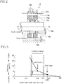
- the floating bush bearing 17 of the present invention is illustrated in FIG.2 .
- the configuration of the floating bush bearing 17 is explained in reference to FIG.2 .
- the floating bush 19 forming the floating bush bearing 17 is arranged to have a gap ⁇ so that an oil film is formed between the bearing portion 13d of the bearing housing 13 and an outer peripheral surface 19b of the floating bush 19.
- the rotor shaft 16 is loosely fitted to the floating bush 19 with a gap ⁇ so that an oil film is formed between an inner peripheral surface 19c of the floating bush 19 and the shaft support part 16a of the rotor shaft 16.
- the lubricating oil is fed through the compressor-side lubricating oil passage 13c within the bearing housing 13 (similarly to the turbine-side lubricating oil passage 13b).
- the lubricating oil passes through the oil supply path 19a of the floating bush 19, filling the gap ⁇ between the inner peripheral surface 19c of the floating bush 19 and the shaft support part 16a, thereby supporting the rotor shaft 16 in a floating state with the oil film composed of the lubricating oil.
- the floating bush 19 is configured so that an inner bearing width Li of an inner peripheral surface of the floating bush 19 is formed smaller than an outer bearing width Lo of an outer peripheral surface of the floating bush 19.
- the inner bearing width Li of the inner peripheral surface 19c of the floating bush 19 is formed by trimming both ends of the floating bush 19 inwardly into a cone shape. In this embodiment, both ends are cut by the same amount to be symmetrical with respect to the oil supply path 19a.
- Lx is the minimum inner bearing width including a diamter ⁇ of the oil supply path 19a (a lubricating oil path diameter ⁇ ).
- the minimum inner bearing width Lx is the minimum bearing width required to form an oil film thereon for supporting the shaft support part 16a by the inner peripheral surface 19c of the floating bush 19.
- FIG.3 shows calculation of a damping ratio based on experiment results.
- the damping ratio % indicates support stability of the rotor shaft 16 with respect to an inner/outer width ratio Li/Lo of the floating bush 19.
- the inner/outer width ratio Li/Lo is shown on the horizontal axis while the damping ratio % is shown on the longitudinal axis as a parameter defining the damping characteristic of the oil film.
- the higher damping ratio means better support stability of the rotation shaft 16.
- the support of the rotor shaft 16 by the floating bush 19 tends to be unstable when the floating bush 19 is co-rotated at high speed.
- the inner bearing width Li of the floating bush 19 is set smaller than the outer bearing width Lo of the floating bush 19 (Test Case 1 of FIG.3 ).
- the inner/outer width ratio Li/Lo of the floating bush 19 is Lx / Lo ⁇ Li / Lo ⁇ 0.5.
- the damping ratio is improved from 2% of the conventional case to 3.5%, which results in the significantly improved damping ratio.
- the bearing width Li of the inner peripheral surface 19c is set to the minimum inner bearing width Lx required to provide the hole diametercpof the oil supply path 19a and to form an oil film.
- the co-rotation amount of the floating bush 19 can be optimized in the high-speed rotational range of the rotor shaft 16.
- the oil film formed between the inner peripheral surface 19c of the floating bush 19 and the rotor shaft 16 becomes the sliding surface for supporting rotation of the rotor shaft 16.
- the rotation sliding resistance and oscillation of the rotor shaft 16 can increase, and oscillation stability of the rotor shaft 16 can be improved.
- first floating bush bearing 17 and the second floating bush bearing 18 have the same configuration, viscosity resistance generated at the first and the second floating bushes is the same. As a result, the support of rotor shat 16 becomes stable and the risk of misassembling is reduce. This achieves improved quality and reduced production cost.
- the ratio of the inner bearing width Li to the outer bearing width Lo of the floating bush 19 is set to Lx/Lo ⁇ Li/Lo ⁇ 0.5 to achieve stable support of the rotor shaft 16 during the high speed rotation.
- Lx/Lo ⁇ Li/Lo ⁇ 0.5 to achieve stable support of the rotor shaft 16 during the high speed rotation.
- the floating bush 19 to co-rotate at an early stage and thus, it is necessary to improve starting performance of the turbocharger 1 by reducing the rotation resistance of the rotor shaft 16.
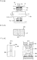
- FIG.4A illustrates a low friction treatment provided on an outer peripheral part of the floating bush according to a first reference example.
- FIG.4A shows an enlarged cross-sectional view of the floating bush 19 provided with the low friction treatment on the outer peripheral part to cause co-rotation of the floating bush 19 at an early stage in the low-speed rotational range of the rotor shaft 16.
- DLC Diamond Like Carbon
- the DLC used here may be metal-containing DLC (WC : tungsten carbide, Si : silicon), hydrogen containing DLC, or the like.
- the DLC coating is normally formed by, but not particularly limited to, chemical vapor deposition (CVD)
- the DLC film is hard and fragile and thus, to improve adhesion of the film to a base material (the floating bush), a substrate material may be provided between the base material (the floating bush) and the DLC film.
- the substrate material may be a single layer of or multiple layers of combination of chromium (Cr), chromium nitride (CrN), titanium (Ti), titanium nitride (TiN), tungsten carbide(WC), tungsten (W), nickel (Ni), copper (Cu), iron (Fe), iron nitride (FeN), silicon (Si), silicon carbide (Sic), etc.
- the outer peripheral surface of the floating bush 19 of the low friction treatment 19d e.g. DLC coating
- FIG.4B illustrates a low friction treatment of a second reference example.
- dimples 27s are provided, as the low friction treatment in the outer peripheral surface of a floating bush 27.
- the lubricant oil is retained in depressions of the dimples 27a, thereby reducing sliding resistance between the outer peripheral surface of the floating bush 27 and the oil film which intervenes between the bearing portion 13d and the floating bush 27.
- the dimples 27a may be formed, but not limit to, by fine particle shot peening.
- the dimples 27a have hemispheric shapes. This is, however, not restrictive and the dimples may have any shape such as a triangular pyramid as long as the shape allows the lubricating oil to retained in the dimples and achieves reduction of the friction coefficient.
- FIG.4C illustrates a low friction treatment of a third reference example in (C1).
- FIG.4C shows in (C2) a longitudinal cross-sectional view of (C1) in the radial direction.
- a center groove 30d is provided in an outer peripheral surface 30a of the floating bush 30 over the entire circumference of outer peripheral surface 30a approximately at the center of the outer peripheral surface 30a in the bearing width direction.
- the center groove 30d communicates with an oil supply hole 30c which penetrates the floating bush 30 from the outer peripheral surface 30a to the inner peripheral surface 30b.
- the lubricating oil fed from the lubricating oil path 13c flows to a lower part of the floating bush 30 via the center groove 30d, thereby filling the space between the floating bush 30 and the bearing portion 13d. As a result, the friction resistance at the start of rotation of the floating bush 30 can be reduced.
- FIG.4D illustrates a low friction treatment of an embodiment in (D1).
- FIG.4D shows in (D2) a longitudinal cross-sectional view of (D1) in the radial direction.
- an oil supply hole 35c is provided approximately at the center of the outer peripheral surface 35a of the floating bush 35 in the bearing width direction. The oil supply hole 35c penetrates the floating bush 35 from the outer peripheral surface 30a to the inner peripheral surface 30b.
- a pair of edge grooves 35d, 35d is formed over the entire circumference of the outer peripheral surface 35a.
- a transverse groove 35e is provided for each oil supply hole 35c so that the edge groove 35d communicates with the oil supply hole 35c.
- the lubricating oil fed from the lubricating oil path 13c flows to a lower part of the floating bush 35 (as indicated by arrows) via the edge grooves 35d, 35d, thereby filling the space between the floating bush 35 and the bearing portion 13d. As a result, the friction resistance during rotation start of the floating bush 35 can be suppressed.
- the inner bearing width is set smaller than the outer bearing width to reduce the co-rotation amount of the floating bush during the high-speed rotation and improve the oscillation stability, thereby achieving the noise reduction effect.
- the sliding resistance during the low-speed rotation of the rotor shaft 16 can be improved.
- the floating bushes 19 (20) have the same ratio of the inner bearing width Li to the outer bearing width Lo, viscosity resistance of the lubricating oil is the same for the floating bushes 19 (20).
- the rotor shaft 16 can be stably support, and misassembling of the floating bushes 19 (20) can be eliminated, which achieves the cost reduction.
- the co-rotation amount of the floating bush 19 (20) is optimized with respect to the rotation speed of the rotor shaft 16.
- the co-rotation amount of each floating bush can be lowered during the high-speed rotation of the rotor shaft 16, and with improved oscillation stability, it is possible to obtain the noise reduction effect.
- the above floating bearing is suitable as a bearing for a high-speed rotation shaft, and is suitable for use in a rotary machine, such as a turbocharger, revolving at high speed, so as to maintain favorable supply of the lubricant oil to the inner peripheral surface of the floating bush at low cost and to lower the noise and rotation resistance by stably supporting the rotation shaft.
Landscapes
- Engineering & Computer Science (AREA)
- General Engineering & Computer Science (AREA)
- Mechanical Engineering (AREA)
- Chemical & Material Sciences (AREA)
- Combustion & Propulsion (AREA)
- Supercharger (AREA)
- Sliding-Contact Bearings (AREA)
Applications Claiming Priority (2)
| Application Number | Priority Date | Filing Date | Title |
|---|---|---|---|
| JP2011145797A JP5705665B2 (ja) | 2011-06-30 | 2011-06-30 | ターボチャージャの軸受装置 |
| PCT/JP2012/066000 WO2013002142A1 (ja) | 2011-06-30 | 2012-06-22 | ターボチャージャの軸受装置 |
Publications (3)
| Publication Number | Publication Date |
|---|---|
| EP2728212A1 EP2728212A1 (en) | 2014-05-07 |
| EP2728212A4 EP2728212A4 (en) | 2015-03-11 |
| EP2728212B1 true EP2728212B1 (en) | 2020-10-14 |
Family
ID=47424037
Family Applications (1)
| Application Number | Title | Priority Date | Filing Date |
|---|---|---|---|
| EP12803917.9A Active EP2728212B1 (en) | 2011-06-30 | 2012-06-22 | Bearing device for turbocharger |
Country Status (5)
| Country | Link |
|---|---|
| US (1) | US9587515B2 (enExample) |
| EP (1) | EP2728212B1 (enExample) |
| JP (1) | JP5705665B2 (enExample) |
| CN (1) | CN103597227B (enExample) |
| WO (1) | WO2013002142A1 (enExample) |
Families Citing this family (22)
| Publication number | Priority date | Publication date | Assignee | Title |
|---|---|---|---|---|
| US9909450B1 (en) * | 2013-03-13 | 2018-03-06 | Us Synthetic Corporation | Turbine assembly including at least one superhard bearing |
| CN105492739A (zh) * | 2013-09-05 | 2016-04-13 | 博格华纳公司 | 用于涡轮增压器的挠曲支点可倾瓦块轴颈轴承 |
| GB201401704D0 (en) * | 2014-01-31 | 2014-03-19 | Cummins Ltd | Turbocharger system |
| CN105940229B (zh) * | 2014-02-27 | 2018-09-28 | 三菱重工发动机和增压器株式会社 | 浮动衬套轴承装置以及具有该轴承装置的涡轮增压器 |
| DE102014208078A1 (de) * | 2014-04-29 | 2015-10-29 | Bosch Mahle Turbo Systems Gmbh & Co. Kg | Abgasturbolader mit einem Rotor |
| CN106460183A (zh) * | 2014-06-25 | 2017-02-22 | 株式会社Ihi | 抑制污染物的附着的被膜及具备该被膜的流路部件 |
| WO2016031013A1 (ja) * | 2014-08-28 | 2016-03-03 | 三菱重工業株式会社 | 軸受装置、及び回転機械 |
| US9695708B2 (en) | 2015-04-12 | 2017-07-04 | Honeywell International Inc. | Turbocharger spring assembly |
| US10208623B2 (en) * | 2015-04-12 | 2019-02-19 | Garrett Transportation I Inc. | Turbocharger bearing assembly |
| US9976476B2 (en) | 2015-04-12 | 2018-05-22 | Honeywell International Inc. | Turbocharger bearing assembly |
| CN106481671A (zh) * | 2015-08-27 | 2017-03-08 | 长城汽车股份有限公司 | 用于增压器的轴承座、增压器和汽车 |
| JP6368864B2 (ja) * | 2015-09-14 | 2018-08-01 | 三菱重工エンジン&ターボチャージャ株式会社 | ターボチャージャ |
| EP3406959B1 (en) * | 2016-03-01 | 2020-04-22 | Mitsubishi Heavy Industries Engine & Turbocharger, Ltd. | Bearing device and exhaust turbine supercharger |
| DE102017126950A1 (de) * | 2017-11-16 | 2019-05-16 | Man Energy Solutions Se | Turbolader |
| DE112019002201T5 (de) | 2018-04-27 | 2021-01-07 | Ihi Corporation | Lager und Turbolader |
| CN108894831B (zh) * | 2018-07-03 | 2021-05-14 | 广州粤能电力科技开发有限公司 | 汽轮机的辅助设备、汽轮机 |
| KR102112409B1 (ko) * | 2018-09-11 | 2020-05-18 | 정일헌 | 타원형 딤플을 가진 부싱 |
| US10557498B1 (en) * | 2018-10-12 | 2020-02-11 | Borgwarner Inc. | Full-floating bearing and turbocharger including the same |
| CN109185147B (zh) * | 2018-10-29 | 2024-07-09 | 珠海格力节能环保制冷技术研究中心有限公司 | 泵体组件、压缩机 |
| JP7341218B2 (ja) * | 2019-02-27 | 2023-09-08 | 三菱重工エンジン&ターボチャージャ株式会社 | 浮動ブッシュ軸受および過給機 |
| JP7114520B2 (ja) * | 2019-03-26 | 2022-08-08 | Ntn株式会社 | スラストフォイル軸受、フォイル軸受ユニット、ターボ機械及びフォイル |
| CN113775651B (zh) * | 2021-09-02 | 2023-10-31 | 华南泵业有限公司 | 一种用水润滑轴承的闸门泵 |
Citations (2)
| Publication number | Priority date | Publication date | Assignee | Title |
|---|---|---|---|---|
| JPS6388318A (ja) * | 1986-10-01 | 1988-04-19 | Hitachi Ltd | 排気タ−ビン過給機 |
| US7189005B2 (en) * | 2005-03-14 | 2007-03-13 | Borgwarner Inc. | Bearing system for a turbocharger |
Family Cites Families (28)
| Publication number | Priority date | Publication date | Assignee | Title |
|---|---|---|---|---|
| JPS56138423A (en) * | 1980-04-01 | 1981-10-29 | Toyota Motor Corp | Structure of bearing of turbosupercharger |
| JPS57129919A (en) * | 1981-02-04 | 1982-08-12 | Hitachi Ltd | Floating bush bearing |
| EP0092920B1 (en) * | 1982-04-22 | 1987-03-04 | Holset Engineering Company Limited | Turbocharger |
| JPS59184327U (ja) * | 1983-05-27 | 1984-12-07 | 株式会社日立製作所 | 排気タ−ビン式過給機の軸封構造 |
| JPS6237625U (enExample) * | 1985-08-22 | 1987-03-05 | ||
| JPS634056A (ja) | 1986-06-24 | 1988-01-09 | Toyota Motor Corp | タ−ボチヤ−ジヤのフロ−テイングベアリング |
| JPH0536995Y2 (enExample) * | 1987-09-18 | 1993-09-20 | ||
| US4969805A (en) * | 1989-05-02 | 1990-11-13 | Allied-Signal Inc. | Unidirectional turbocharger assembly |
| DE4002583C1 (enExample) * | 1990-01-30 | 1991-05-29 | Aktiengesellschaft Kuehnle, Kopp & Kausch, 6710 Frankenthal, De | |
| JP3432303B2 (ja) | 1994-09-08 | 2003-08-04 | 川崎重工業株式会社 | 二重反転プロペラ用反転軸受 |
| JP2000087961A (ja) * | 1998-09-18 | 2000-03-28 | Unisia Jecs Corp | 軸受構造並びにこれを用いた内燃機関の可変動弁装置 |
| US7132936B1 (en) * | 1999-04-20 | 2006-11-07 | Peter Norton | Angular rate sensor |
| JP4386563B2 (ja) * | 2000-11-07 | 2009-12-16 | 株式会社日本自動車部品総合研究所 | ターボチャージャの軸受装置 |
| JP2003013710A (ja) * | 2001-07-02 | 2003-01-15 | Nissan Motor Co Ltd | 摺動装置及び内燃機関の動弁機構 |
| JP2003184883A (ja) | 2001-12-20 | 2003-07-03 | Nissan Motor Co Ltd | 軸受摺動部材 |
| DE10311202A1 (de) * | 2003-03-14 | 2004-10-14 | Man B & W Diesel Ag | Lager für eine mit hoher Drehzahl umlaufende Welle |
| JP2006090402A (ja) | 2004-09-22 | 2006-04-06 | Nsk Ltd | ターボチャージャ用回転支持装置 |
| JP2007046642A (ja) | 2005-08-08 | 2007-02-22 | Toyota Motor Corp | 過給機およびフルフロートベアリング |
| KR101455406B1 (ko) | 2006-03-31 | 2014-10-27 | 이데미쓰 고산 가부시키가이샤 | 윤활유 첨가제, 그것을 함유하는 윤활유 조성물, 각종 저마찰 접동 부재, 롤링 베어링 및 슬라이딩 베어링 |
| US7793499B2 (en) * | 2006-10-25 | 2010-09-14 | Honeywell International Inc. | Bearing spacer and housing |
| JP5082477B2 (ja) * | 2007-02-07 | 2012-11-28 | 株式会社Ihi | 浮動ブッシュ軸受構造 |
| JP2009007935A (ja) * | 2007-06-26 | 2009-01-15 | Hitachi Ltd | ターボチャージャ |
| JP2009156333A (ja) | 2007-12-26 | 2009-07-16 | Ihi Corp | 回転機械の軸受装置 |
| GB0801845D0 (en) * | 2008-02-01 | 2008-03-05 | Cummins Turbo Tech Ltd | A Shaft bearing assembly |
| JP4969531B2 (ja) | 2008-08-12 | 2012-07-04 | 三菱重工業株式会社 | 浮動ブッシュ軸受 |
| JP5359206B2 (ja) | 2008-11-11 | 2013-12-04 | トヨタ自動車株式会社 | 浮動ブッシュ軸受式の軸受装置及びこれを備える内燃機関の過給機 |
| JP2010138757A (ja) | 2008-12-10 | 2010-06-24 | Toyota Motor Corp | ターボチャージャ |
| DE102009007696A1 (de) * | 2009-02-05 | 2010-08-12 | Bosch Mahle Turbo Systems Gmbh & Co. Kg | Lageranordnung |
-
2011
- 2011-06-30 JP JP2011145797A patent/JP5705665B2/ja not_active Expired - Fee Related
-
2012
- 2012-06-22 WO PCT/JP2012/066000 patent/WO2013002142A1/ja not_active Ceased
- 2012-06-22 US US14/125,810 patent/US9587515B2/en not_active Expired - Fee Related
- 2012-06-22 CN CN201280027265.XA patent/CN103597227B/zh active Active
- 2012-06-22 EP EP12803917.9A patent/EP2728212B1/en active Active
Patent Citations (2)
| Publication number | Priority date | Publication date | Assignee | Title |
|---|---|---|---|---|
| JPS6388318A (ja) * | 1986-10-01 | 1988-04-19 | Hitachi Ltd | 排気タ−ビン過給機 |
| US7189005B2 (en) * | 2005-03-14 | 2007-03-13 | Borgwarner Inc. | Bearing system for a turbocharger |
Also Published As
| Publication number | Publication date |
|---|---|
| JP2013011331A (ja) | 2013-01-17 |
| US20140119898A1 (en) | 2014-05-01 |
| EP2728212A4 (en) | 2015-03-11 |
| CN103597227B (zh) | 2016-04-13 |
| JP5705665B2 (ja) | 2015-04-22 |
| EP2728212A1 (en) | 2014-05-07 |
| CN103597227A (zh) | 2014-02-19 |
| US9587515B2 (en) | 2017-03-07 |
| WO2013002142A1 (ja) | 2013-01-03 |
Similar Documents
| Publication | Publication Date | Title |
|---|---|---|
| EP2728212B1 (en) | Bearing device for turbocharger | |
| EP1896696B1 (en) | Turbocharger bearing and associated components | |
| EP1972759B1 (en) | Stepped outer diameter semi-floating bearing | |
| CN108825363B (zh) | 轴向轴承安排 | |
| US8449190B2 (en) | Centering mechanisms for turbocharger bearings | |
| EP2728137B1 (en) | Bearing device for turbocharger | |
| EP2208903B1 (en) | Bearing and retention mechanisms | |
| WO2011143079A2 (en) | Exhaust-gas turbocharger | |
| EP2163731B1 (en) | High performance thrust bearing pad | |
| US20150078689A1 (en) | Journal bearing | |
| JP2011153668A (ja) | 軸受装置 | |
| JP2013002559A (ja) | 排気ターボ過給機のスラスト軸受装置 | |
| US10077802B2 (en) | Tilting pad journal bearing assembly | |
| JP2013245663A (ja) | 過給機 | |
| EP2037135B1 (en) | Roller bearings, and struts and gas turbine engines involving such bearings | |
| US20210087945A1 (en) | Turbocharger for an internal combustion engine | |
| US20160281535A1 (en) | Bearing device for a turbocharger and turbocharger | |
| US10125818B2 (en) | Turbomachine shaft and journal bearing assembly | |
| JP2016536537A (ja) | ピストンピン及びピンに焼き付き防止コーティングを適用する方法 | |
| US10975727B2 (en) | Bearing bush of a turbocharger and turbocharger | |
| JP2011196248A (ja) | 過給機 | |
| CN111271372B (zh) | 一种倒置式三油叶芯棒结构滑动轴承 | |
| JP2017223317A (ja) | ターボチャージャ用軸受機構 | |
| JP2008215086A (ja) | ターボチャージャの軸受構造 |
Legal Events
| Date | Code | Title | Description |
|---|---|---|---|
| TPAC | Observations filed by third parties |
Free format text: ORIGINAL CODE: EPIDOSNTIPA |
|
| PUAI | Public reference made under article 153(3) epc to a published international application that has entered the european phase |
Free format text: ORIGINAL CODE: 0009012 |
|
| 17P | Request for examination filed |
Effective date: 20131210 |
|
| AK | Designated contracting states |
Kind code of ref document: A1 Designated state(s): AL AT BE BG CH CY CZ DE DK EE ES FI FR GB GR HR HU IE IS IT LI LT LU LV MC MK MT NL NO PL PT RO RS SE SI SK SM TR |
|
| DAX | Request for extension of the european patent (deleted) | ||
| A4 | Supplementary search report drawn up and despatched |
Effective date: 20150211 |
|
| RIC1 | Information provided on ipc code assigned before grant |
Ipc: F16C 17/02 20060101ALN20150205BHEP Ipc: F02B 39/14 20060101ALI20150205BHEP Ipc: F16C 33/10 20060101ALN20150205BHEP Ipc: F16C 27/02 20060101ALI20150205BHEP Ipc: F01D 25/18 20060101ALN20150205BHEP Ipc: F16C 17/18 20060101AFI20150205BHEP Ipc: F02B 39/00 20060101ALI20150205BHEP Ipc: F01D 25/16 20060101ALI20150205BHEP |
|
| STAA | Information on the status of an ep patent application or granted ep patent |
Free format text: STATUS: EXAMINATION IS IN PROGRESS |
|
| 17Q | First examination report despatched |
Effective date: 20200120 |
|
| GRAP | Despatch of communication of intention to grant a patent |
Free format text: ORIGINAL CODE: EPIDOSNIGR1 |
|
| STAA | Information on the status of an ep patent application or granted ep patent |
Free format text: STATUS: GRANT OF PATENT IS INTENDED |
|
| RIC1 | Information provided on ipc code assigned before grant |
Ipc: F16C 33/10 20060101ALI20200529BHEP Ipc: F02B 39/00 20060101ALI20200529BHEP Ipc: F01D 25/18 20060101ALN20200529BHEP Ipc: F16C 17/26 20060101ALN20200529BHEP Ipc: F16C 27/02 20060101ALI20200529BHEP Ipc: F16C 17/02 20060101ALN20200529BHEP Ipc: F01D 25/16 20060101ALI20200529BHEP Ipc: F16C 17/18 20060101AFI20200529BHEP Ipc: F02B 39/14 20060101ALI20200529BHEP |
|
| RIC1 | Information provided on ipc code assigned before grant |
Ipc: F16C 33/10 20060101ALI20200605BHEP Ipc: F16C 17/02 20060101ALN20200605BHEP Ipc: F02B 39/14 20060101ALI20200605BHEP Ipc: F01D 25/16 20060101ALI20200605BHEP Ipc: F01D 25/18 20060101ALN20200605BHEP Ipc: F02B 39/00 20060101ALI20200605BHEP Ipc: F16C 27/02 20060101ALI20200605BHEP Ipc: F16C 17/18 20060101AFI20200605BHEP Ipc: F16C 17/26 20060101ALN20200605BHEP |
|
| INTG | Intention to grant announced |
Effective date: 20200629 |
|
| GRAS | Grant fee paid |
Free format text: ORIGINAL CODE: EPIDOSNIGR3 |
|
| GRAA | (expected) grant |
Free format text: ORIGINAL CODE: 0009210 |
|
| STAA | Information on the status of an ep patent application or granted ep patent |
Free format text: STATUS: THE PATENT HAS BEEN GRANTED |
|
| AK | Designated contracting states |
Kind code of ref document: B1 Designated state(s): AL AT BE BG CH CY CZ DE DK EE ES FI FR GB GR HR HU IE IS IT LI LT LU LV MC MK MT NL NO PL PT RO RS SE SI SK SM TR |
|
| REG | Reference to a national code |
Ref country code: GB Ref legal event code: FG4D |
|
| REG | Reference to a national code |
Ref country code: AT Ref legal event code: REF Ref document number: 1323893 Country of ref document: AT Kind code of ref document: T Effective date: 20201015 Ref country code: CH Ref legal event code: EP |
|
| REG | Reference to a national code |
Ref country code: DE Ref legal event code: R096 Ref document number: 602012072807 Country of ref document: DE |
|
| REG | Reference to a national code |
Ref country code: IE Ref legal event code: FG4D |
|
| REG | Reference to a national code |
Ref country code: NL Ref legal event code: FP |
|
| REG | Reference to a national code |
Ref country code: AT Ref legal event code: MK05 Ref document number: 1323893 Country of ref document: AT Kind code of ref document: T Effective date: 20201014 |
|
| PG25 | Lapsed in a contracting state [announced via postgrant information from national office to epo] |
Ref country code: RS Free format text: LAPSE BECAUSE OF FAILURE TO SUBMIT A TRANSLATION OF THE DESCRIPTION OR TO PAY THE FEE WITHIN THE PRESCRIBED TIME-LIMIT Effective date: 20201014 Ref country code: FI Free format text: LAPSE BECAUSE OF FAILURE TO SUBMIT A TRANSLATION OF THE DESCRIPTION OR TO PAY THE FEE WITHIN THE PRESCRIBED TIME-LIMIT Effective date: 20201014 Ref country code: NO Free format text: LAPSE BECAUSE OF FAILURE TO SUBMIT A TRANSLATION OF THE DESCRIPTION OR TO PAY THE FEE WITHIN THE PRESCRIBED TIME-LIMIT Effective date: 20210114 Ref country code: PT Free format text: LAPSE BECAUSE OF FAILURE TO SUBMIT A TRANSLATION OF THE DESCRIPTION OR TO PAY THE FEE WITHIN THE PRESCRIBED TIME-LIMIT Effective date: 20210215 Ref country code: GR Free format text: LAPSE BECAUSE OF FAILURE TO SUBMIT A TRANSLATION OF THE DESCRIPTION OR TO PAY THE FEE WITHIN THE PRESCRIBED TIME-LIMIT Effective date: 20210115 |
|
| REG | Reference to a national code |
Ref country code: LT Ref legal event code: MG4D |
|
| PG25 | Lapsed in a contracting state [announced via postgrant information from national office to epo] |
Ref country code: SE Free format text: LAPSE BECAUSE OF FAILURE TO SUBMIT A TRANSLATION OF THE DESCRIPTION OR TO PAY THE FEE WITHIN THE PRESCRIBED TIME-LIMIT Effective date: 20201014 Ref country code: IS Free format text: LAPSE BECAUSE OF FAILURE TO SUBMIT A TRANSLATION OF THE DESCRIPTION OR TO PAY THE FEE WITHIN THE PRESCRIBED TIME-LIMIT Effective date: 20210214 Ref country code: PL Free format text: LAPSE BECAUSE OF FAILURE TO SUBMIT A TRANSLATION OF THE DESCRIPTION OR TO PAY THE FEE WITHIN THE PRESCRIBED TIME-LIMIT Effective date: 20201014 Ref country code: LV Free format text: LAPSE BECAUSE OF FAILURE TO SUBMIT A TRANSLATION OF THE DESCRIPTION OR TO PAY THE FEE WITHIN THE PRESCRIBED TIME-LIMIT Effective date: 20201014 Ref country code: ES Free format text: LAPSE BECAUSE OF FAILURE TO SUBMIT A TRANSLATION OF THE DESCRIPTION OR TO PAY THE FEE WITHIN THE PRESCRIBED TIME-LIMIT Effective date: 20201014 Ref country code: AT Free format text: LAPSE BECAUSE OF FAILURE TO SUBMIT A TRANSLATION OF THE DESCRIPTION OR TO PAY THE FEE WITHIN THE PRESCRIBED TIME-LIMIT Effective date: 20201014 Ref country code: BG Free format text: LAPSE BECAUSE OF FAILURE TO SUBMIT A TRANSLATION OF THE DESCRIPTION OR TO PAY THE FEE WITHIN THE PRESCRIBED TIME-LIMIT Effective date: 20210114 |
|
| PG25 | Lapsed in a contracting state [announced via postgrant information from national office to epo] |
Ref country code: HR Free format text: LAPSE BECAUSE OF FAILURE TO SUBMIT A TRANSLATION OF THE DESCRIPTION OR TO PAY THE FEE WITHIN THE PRESCRIBED TIME-LIMIT Effective date: 20201014 |
|
| REG | Reference to a national code |
Ref country code: DE Ref legal event code: R097 Ref document number: 602012072807 Country of ref document: DE |
|
| PG25 | Lapsed in a contracting state [announced via postgrant information from national office to epo] |
Ref country code: RO Free format text: LAPSE BECAUSE OF FAILURE TO SUBMIT A TRANSLATION OF THE DESCRIPTION OR TO PAY THE FEE WITHIN THE PRESCRIBED TIME-LIMIT Effective date: 20201014 Ref country code: SK Free format text: LAPSE BECAUSE OF FAILURE TO SUBMIT A TRANSLATION OF THE DESCRIPTION OR TO PAY THE FEE WITHIN THE PRESCRIBED TIME-LIMIT Effective date: 20201014 Ref country code: LT Free format text: LAPSE BECAUSE OF FAILURE TO SUBMIT A TRANSLATION OF THE DESCRIPTION OR TO PAY THE FEE WITHIN THE PRESCRIBED TIME-LIMIT Effective date: 20201014 Ref country code: CZ Free format text: LAPSE BECAUSE OF FAILURE TO SUBMIT A TRANSLATION OF THE DESCRIPTION OR TO PAY THE FEE WITHIN THE PRESCRIBED TIME-LIMIT Effective date: 20201014 Ref country code: EE Free format text: LAPSE BECAUSE OF FAILURE TO SUBMIT A TRANSLATION OF THE DESCRIPTION OR TO PAY THE FEE WITHIN THE PRESCRIBED TIME-LIMIT Effective date: 20201014 Ref country code: SM Free format text: LAPSE BECAUSE OF FAILURE TO SUBMIT A TRANSLATION OF THE DESCRIPTION OR TO PAY THE FEE WITHIN THE PRESCRIBED TIME-LIMIT Effective date: 20201014 |
|
| PLBE | No opposition filed within time limit |
Free format text: ORIGINAL CODE: 0009261 |
|
| STAA | Information on the status of an ep patent application or granted ep patent |
Free format text: STATUS: NO OPPOSITION FILED WITHIN TIME LIMIT |
|
| PG25 | Lapsed in a contracting state [announced via postgrant information from national office to epo] |
Ref country code: DK Free format text: LAPSE BECAUSE OF FAILURE TO SUBMIT A TRANSLATION OF THE DESCRIPTION OR TO PAY THE FEE WITHIN THE PRESCRIBED TIME-LIMIT Effective date: 20201014 |
|
| 26N | No opposition filed |
Effective date: 20210715 |
|
| PG25 | Lapsed in a contracting state [announced via postgrant information from national office to epo] |
Ref country code: AL Free format text: LAPSE BECAUSE OF FAILURE TO SUBMIT A TRANSLATION OF THE DESCRIPTION OR TO PAY THE FEE WITHIN THE PRESCRIBED TIME-LIMIT Effective date: 20201014 Ref country code: IT Free format text: LAPSE BECAUSE OF FAILURE TO SUBMIT A TRANSLATION OF THE DESCRIPTION OR TO PAY THE FEE WITHIN THE PRESCRIBED TIME-LIMIT Effective date: 20201014 |
|
| PG25 | Lapsed in a contracting state [announced via postgrant information from national office to epo] |
Ref country code: SI Free format text: LAPSE BECAUSE OF FAILURE TO SUBMIT A TRANSLATION OF THE DESCRIPTION OR TO PAY THE FEE WITHIN THE PRESCRIBED TIME-LIMIT Effective date: 20201014 |
|
| PG25 | Lapsed in a contracting state [announced via postgrant information from national office to epo] |
Ref country code: MC Free format text: LAPSE BECAUSE OF FAILURE TO SUBMIT A TRANSLATION OF THE DESCRIPTION OR TO PAY THE FEE WITHIN THE PRESCRIBED TIME-LIMIT Effective date: 20201014 |
|
| REG | Reference to a national code |
Ref country code: CH Ref legal event code: PL |
|
| REG | Reference to a national code |
Ref country code: BE Ref legal event code: MM Effective date: 20210630 |
|
| PG25 | Lapsed in a contracting state [announced via postgrant information from national office to epo] |
Ref country code: LU Free format text: LAPSE BECAUSE OF NON-PAYMENT OF DUE FEES Effective date: 20210622 |
|
| PG25 | Lapsed in a contracting state [announced via postgrant information from national office to epo] |
Ref country code: LI Free format text: LAPSE BECAUSE OF NON-PAYMENT OF DUE FEES Effective date: 20210630 Ref country code: IE Free format text: LAPSE BECAUSE OF NON-PAYMENT OF DUE FEES Effective date: 20210622 Ref country code: CH Free format text: LAPSE BECAUSE OF NON-PAYMENT OF DUE FEES Effective date: 20210630 |
|
| PG25 | Lapsed in a contracting state [announced via postgrant information from national office to epo] |
Ref country code: IS Free format text: LAPSE BECAUSE OF FAILURE TO SUBMIT A TRANSLATION OF THE DESCRIPTION OR TO PAY THE FEE WITHIN THE PRESCRIBED TIME-LIMIT Effective date: 20210214 |
|
| PGFP | Annual fee paid to national office [announced via postgrant information from national office to epo] |
Ref country code: NL Payment date: 20220513 Year of fee payment: 11 |
|
| PG25 | Lapsed in a contracting state [announced via postgrant information from national office to epo] |
Ref country code: BE Free format text: LAPSE BECAUSE OF NON-PAYMENT OF DUE FEES Effective date: 20210630 |
|
| PGFP | Annual fee paid to national office [announced via postgrant information from national office to epo] |
Ref country code: GB Payment date: 20220428 Year of fee payment: 11 Ref country code: FR Payment date: 20220510 Year of fee payment: 11 |
|
| PG25 | Lapsed in a contracting state [announced via postgrant information from national office to epo] |
Ref country code: HU Free format text: LAPSE BECAUSE OF FAILURE TO SUBMIT A TRANSLATION OF THE DESCRIPTION OR TO PAY THE FEE WITHIN THE PRESCRIBED TIME-LIMIT; INVALID AB INITIO Effective date: 20120622 Ref country code: CY Free format text: LAPSE BECAUSE OF FAILURE TO SUBMIT A TRANSLATION OF THE DESCRIPTION OR TO PAY THE FEE WITHIN THE PRESCRIBED TIME-LIMIT Effective date: 20201014 |
|
| REG | Reference to a national code |
Ref country code: NL Ref legal event code: MM Effective date: 20230701 |
|
| GBPC | Gb: european patent ceased through non-payment of renewal fee |
Effective date: 20230622 |
|
| PG25 | Lapsed in a contracting state [announced via postgrant information from national office to epo] |
Ref country code: NL Free format text: LAPSE BECAUSE OF NON-PAYMENT OF DUE FEES Effective date: 20230701 |
|
| PG25 | Lapsed in a contracting state [announced via postgrant information from national office to epo] |
Ref country code: MK Free format text: LAPSE BECAUSE OF FAILURE TO SUBMIT A TRANSLATION OF THE DESCRIPTION OR TO PAY THE FEE WITHIN THE PRESCRIBED TIME-LIMIT Effective date: 20201014 Ref country code: GB Free format text: LAPSE BECAUSE OF NON-PAYMENT OF DUE FEES Effective date: 20230622 |
|
| PG25 | Lapsed in a contracting state [announced via postgrant information from national office to epo] |
Ref country code: FR Free format text: LAPSE BECAUSE OF NON-PAYMENT OF DUE FEES Effective date: 20230630 |
|
| PG25 | Lapsed in a contracting state [announced via postgrant information from national office to epo] |
Ref country code: MT Free format text: LAPSE BECAUSE OF FAILURE TO SUBMIT A TRANSLATION OF THE DESCRIPTION OR TO PAY THE FEE WITHIN THE PRESCRIBED TIME-LIMIT Effective date: 20201014 |
|
| PGFP | Annual fee paid to national office [announced via postgrant information from national office to epo] |
Ref country code: DE Payment date: 20250429 Year of fee payment: 14 |
|
| PG25 | Lapsed in a contracting state [announced via postgrant information from national office to epo] |
Ref country code: TR Free format text: LAPSE BECAUSE OF FAILURE TO SUBMIT A TRANSLATION OF THE DESCRIPTION OR TO PAY THE FEE WITHIN THE PRESCRIBED TIME-LIMIT Effective date: 20201014 |