EP2722211A1 - Vorrichtung zur installation einer fahrzeugbatterieeinheit - Google Patents
Vorrichtung zur installation einer fahrzeugbatterieeinheit Download PDFInfo
- Publication number
- EP2722211A1 EP2722211A1 EP12802669.7A EP12802669A EP2722211A1 EP 2722211 A1 EP2722211 A1 EP 2722211A1 EP 12802669 A EP12802669 A EP 12802669A EP 2722211 A1 EP2722211 A1 EP 2722211A1
- Authority
- EP
- European Patent Office
- Prior art keywords
- battery unit
- base plate
- frame
- striker
- installation apparatus
- Prior art date
- Legal status (The legal status is an assumption and is not a legal conclusion. Google has not performed a legal analysis and makes no representation as to the accuracy of the status listed.)
- Withdrawn
Links
Images


Classifications
-
- B—PERFORMING OPERATIONS; TRANSPORTING
- B60—VEHICLES IN GENERAL
- B60K—ARRANGEMENT OR MOUNTING OF PROPULSION UNITS OR OF TRANSMISSIONS IN VEHICLES; ARRANGEMENT OR MOUNTING OF PLURAL DIVERSE PRIME-MOVERS IN VEHICLES; AUXILIARY DRIVES FOR VEHICLES; INSTRUMENTATION OR DASHBOARDS FOR VEHICLES; ARRANGEMENTS IN CONNECTION WITH COOLING, AIR INTAKE, GAS EXHAUST OR FUEL SUPPLY OF PROPULSION UNITS IN VEHICLES
- B60K1/00—Arrangement or mounting of electrical propulsion units
- B60K1/04—Arrangement or mounting of electrical propulsion units of the electric storage means for propulsion
-
- B—PERFORMING OPERATIONS; TRANSPORTING
- B60—VEHICLES IN GENERAL
- B60L—PROPULSION OF ELECTRICALLY-PROPELLED VEHICLES; SUPPLYING ELECTRIC POWER FOR AUXILIARY EQUIPMENT OF ELECTRICALLY-PROPELLED VEHICLES; ELECTRODYNAMIC BRAKE SYSTEMS FOR VEHICLES IN GENERAL; MAGNETIC SUSPENSION OR LEVITATION FOR VEHICLES; MONITORING OPERATING VARIABLES OF ELECTRICALLY-PROPELLED VEHICLES; ELECTRIC SAFETY DEVICES FOR ELECTRICALLY-PROPELLED VEHICLES
- B60L53/00—Methods of charging batteries, specially adapted for electric vehicles; Charging stations or on-board charging equipment therefor; Exchange of energy storage elements in electric vehicles
- B60L53/80—Exchanging energy storage elements, e.g. removable batteries
-
- B—PERFORMING OPERATIONS; TRANSPORTING
- B60—VEHICLES IN GENERAL
- B60K—ARRANGEMENT OR MOUNTING OF PROPULSION UNITS OR OF TRANSMISSIONS IN VEHICLES; ARRANGEMENT OR MOUNTING OF PLURAL DIVERSE PRIME-MOVERS IN VEHICLES; AUXILIARY DRIVES FOR VEHICLES; INSTRUMENTATION OR DASHBOARDS FOR VEHICLES; ARRANGEMENTS IN CONNECTION WITH COOLING, AIR INTAKE, GAS EXHAUST OR FUEL SUPPLY OF PROPULSION UNITS IN VEHICLES
- B60K1/00—Arrangement or mounting of electrical propulsion units
- B60K1/04—Arrangement or mounting of electrical propulsion units of the electric storage means for propulsion
- B60K2001/0405—Arrangement or mounting of electrical propulsion units of the electric storage means for propulsion characterised by their position
- B60K2001/0438—Arrangement under the floor
-
- B—PERFORMING OPERATIONS; TRANSPORTING
- B60—VEHICLES IN GENERAL
- B60K—ARRANGEMENT OR MOUNTING OF PROPULSION UNITS OR OF TRANSMISSIONS IN VEHICLES; ARRANGEMENT OR MOUNTING OF PLURAL DIVERSE PRIME-MOVERS IN VEHICLES; AUXILIARY DRIVES FOR VEHICLES; INSTRUMENTATION OR DASHBOARDS FOR VEHICLES; ARRANGEMENTS IN CONNECTION WITH COOLING, AIR INTAKE, GAS EXHAUST OR FUEL SUPPLY OF PROPULSION UNITS IN VEHICLES
- B60K1/00—Arrangement or mounting of electrical propulsion units
- B60K1/04—Arrangement or mounting of electrical propulsion units of the electric storage means for propulsion
- B60K2001/0455—Removal or replacement of the energy storages
- B60K2001/0472—Removal or replacement of the energy storages from below
-
- B—PERFORMING OPERATIONS; TRANSPORTING
- B60—VEHICLES IN GENERAL
- B60R—VEHICLES, VEHICLE FITTINGS, OR VEHICLE PARTS, NOT OTHERWISE PROVIDED FOR
- B60R16/00—Electric or fluid circuits specially adapted for vehicles and not otherwise provided for; Arrangement of elements of electric or fluid circuits specially adapted for vehicles and not otherwise provided for
- B60R16/02—Electric or fluid circuits specially adapted for vehicles and not otherwise provided for; Arrangement of elements of electric or fluid circuits specially adapted for vehicles and not otherwise provided for electric constitutive elements
- B60R16/04—Arrangement of batteries
-
- Y—GENERAL TAGGING OF NEW TECHNOLOGICAL DEVELOPMENTS; GENERAL TAGGING OF CROSS-SECTIONAL TECHNOLOGIES SPANNING OVER SEVERAL SECTIONS OF THE IPC; TECHNICAL SUBJECTS COVERED BY FORMER USPC CROSS-REFERENCE ART COLLECTIONS [XRACs] AND DIGESTS
- Y02—TECHNOLOGIES OR APPLICATIONS FOR MITIGATION OR ADAPTATION AGAINST CLIMATE CHANGE
- Y02T—CLIMATE CHANGE MITIGATION TECHNOLOGIES RELATED TO TRANSPORTATION
- Y02T10/00—Road transport of goods or passengers
- Y02T10/60—Other road transportation technologies with climate change mitigation effect
- Y02T10/70—Energy storage systems for electromobility, e.g. batteries
-
- Y—GENERAL TAGGING OF NEW TECHNOLOGICAL DEVELOPMENTS; GENERAL TAGGING OF CROSS-SECTIONAL TECHNOLOGIES SPANNING OVER SEVERAL SECTIONS OF THE IPC; TECHNICAL SUBJECTS COVERED BY FORMER USPC CROSS-REFERENCE ART COLLECTIONS [XRACs] AND DIGESTS
- Y02—TECHNOLOGIES OR APPLICATIONS FOR MITIGATION OR ADAPTATION AGAINST CLIMATE CHANGE
- Y02T—CLIMATE CHANGE MITIGATION TECHNOLOGIES RELATED TO TRANSPORTATION
- Y02T10/00—Road transport of goods or passengers
- Y02T10/60—Other road transportation technologies with climate change mitigation effect
- Y02T10/7072—Electromobility specific charging systems or methods for batteries, ultracapacitors, supercapacitors or double-layer capacitors
-
- Y—GENERAL TAGGING OF NEW TECHNOLOGICAL DEVELOPMENTS; GENERAL TAGGING OF CROSS-SECTIONAL TECHNOLOGIES SPANNING OVER SEVERAL SECTIONS OF THE IPC; TECHNICAL SUBJECTS COVERED BY FORMER USPC CROSS-REFERENCE ART COLLECTIONS [XRACs] AND DIGESTS
- Y02—TECHNOLOGIES OR APPLICATIONS FOR MITIGATION OR ADAPTATION AGAINST CLIMATE CHANGE
- Y02T—CLIMATE CHANGE MITIGATION TECHNOLOGIES RELATED TO TRANSPORTATION
- Y02T90/00—Enabling technologies or technologies with a potential or indirect contribution to GHG emissions mitigation
- Y02T90/10—Technologies relating to charging of electric vehicles
- Y02T90/12—Electric charging stations
-
- Y—GENERAL TAGGING OF NEW TECHNOLOGICAL DEVELOPMENTS; GENERAL TAGGING OF CROSS-SECTIONAL TECHNOLOGIES SPANNING OVER SEVERAL SECTIONS OF THE IPC; TECHNICAL SUBJECTS COVERED BY FORMER USPC CROSS-REFERENCE ART COLLECTIONS [XRACs] AND DIGESTS
- Y02—TECHNOLOGIES OR APPLICATIONS FOR MITIGATION OR ADAPTATION AGAINST CLIMATE CHANGE
- Y02T—CLIMATE CHANGE MITIGATION TECHNOLOGIES RELATED TO TRANSPORTATION
- Y02T90/00—Enabling technologies or technologies with a potential or indirect contribution to GHG emissions mitigation
- Y02T90/10—Technologies relating to charging of electric vehicles
- Y02T90/14—Plug-in electric vehicles
-
- Y—GENERAL TAGGING OF NEW TECHNOLOGICAL DEVELOPMENTS; GENERAL TAGGING OF CROSS-SECTIONAL TECHNOLOGIES SPANNING OVER SEVERAL SECTIONS OF THE IPC; TECHNICAL SUBJECTS COVERED BY FORMER USPC CROSS-REFERENCE ART COLLECTIONS [XRACs] AND DIGESTS
- Y10—TECHNICAL SUBJECTS COVERED BY FORMER USPC
- Y10T—TECHNICAL SUBJECTS COVERED BY FORMER US CLASSIFICATION
- Y10T29/00—Metal working
- Y10T29/53—Means to assemble or disassemble
- Y10T29/53961—Means to assemble or disassemble with work-holder for assembly
Definitions
- the present invention relates to a vehicle battery unit installation apparatus used in a vehicle such as an electric vehicle capable of detaching or attaching a battery unit.
- batteries are installed as a supply source of electric power for a traveling motor.
- the batteries are housed in a case as a battery unit.
- the battery unit is installed in the vehicle body.
- the type of the electric vehicle requiring the replacement of the battery unit includes an electric vehicle enabling the installation of a battery unit on the bottom part of a vehicle body and enabling replacement of the battery unit from below the vehicle body by using a battery unit installation apparatus.
- various vehicle battery unit installation apparatuses are proposed in order to install the battery unit in the vehicle body efficiently.
- a vehicle battery unit installation apparatus disclosed in Patent Document 1 includes a bolt, provided to vertically extend on the lower part of a vehicle body, and a nut secured to the bolt.
- a battery unit can be installed in the lower part of the vehicle body by using the bolt and the nut.
- Patent Document 1 Japanese Laid-Open Patent Publication No. 2010-184621
- An object of the present invention is to provide a vehicle battery unit installation apparatus capable of reliably installing a battery unit in a vehicle body.
- One aspect of the present invention provides a vehicle battery unit installation apparatus for installing a battery unit in a lower part of a vehicle body, the vehicle body has a frame configuring a part of a lower surface of the vehicle body in a state where the battery unit is not installed, the vehicle battery unit installation apparatus includes: a striker device configured to be secured to the vehicle body, wherein the striker device includes a base plate, and a striker secured to the base plate, and wherein the striker has a support part capable of supporting a load; and a locking device secured to the battery unit and capable of securing the support part, wherein the base plate is configured to be secured to the frame, and the striker has ends secured to the base plate such that the support part is located below the frame.
- the support part of the striker device secured to the vehicle body is secured to the locking device secured to the battery unit, so that the battery unit can be installed in the lower part of the vehicle body.
- the striker device has the base plate and the striker secured to the base plate.
- the base plate is secured to the frame configuring a part of the lower surface of the vehicle body.
- the striker has the support part.
- the striker has the ends secured to the base plate such that the support part is located below the frame. Therefore, the load of the battery unit is shared by the ends of the support part to be transmitted to the base plate, and is supported by the frame. Therefore, the battery unit can be firmly installed in the vehicle body.
- the battery unit can be reliably installed in the vehicle body.
- the support part is located at the lower part of the frame. Therefore, compared to a case where the support part is located on the side of the frame, the battery unit can be brought closer to the frame and as large a battery unit as possible can be installed in the vehicle body.
- the vehicle battery unit installation apparatus of the present invention can be mainly employed as an apparatus for installing a battery unit in a vehicle body in a vehicle that travels by electric power stored in the batteries. Additionally, the vehicle battery unit installation apparatus can be employed as an apparatus for installing a battery unit in a vehicle body in a vehicle that travels by fuel such as gasoline and gas oil.
- the concept of the vehicle body includes not only vehicle bodies for automobiles, but also vehicle bodies for industrial vehicles such as forklifts, automatic conveyance vehicle, and the like.
- the number of striker devices and the number of locking devices are not limited, and the number of striker devices and the number of locking devices can be arbitrarily changed according to the load of the battery unit.
- the shape thereof is not limited and can be variously changed according to the shape of the vehicle body or the battery unit.
- a space enabling mounting of the battery unit on the lower part of the vehicle body may be provided, and the frame may be provided in the space. Or the frame may protrude to the lower part of the vehicle body.
- the vehicle body and the frame may be integrally formed, or the vehicle body and the frame may be independently formed.
- the frame can have a pair of frame side walls and a frame lower wall connected to lower ends of the frame side walls.
- the base plate can have a base plate lower wall extending substantially parallel to the frame lower wall and secured to the frame lower wall. At least a first end of the striker preferably extends upward from the support part, thereafter preferably extends parallel to the base plate lower wall, and is preferably welded to an upper surface of the base plate lower wall.
- the base plate lower wall can be suitably secured to the frame lower wall. Consequently, the striker device can be firmly secured to the frame, and the aforementioned load of the striker device can be suitably shared by the frame. Additionally, the first end of the striker is secured to the base plate lower wall in a state of being placed on the upper surface of the base plate lower wall, and hence one end of the support part is reliably supported on the upper surface of the base plate lower wall. Thus, the durability of the striker device is improved, and the reliability of the installation of the battery unit in the vehicle body is improved.
- the base plate can have a base plate side wall formed by bending and extending an end of the base plate lower wall along the frame side walls.
- a second end of the striker preferably extends upward from the support part and is preferably welded to the base plate side wall.
- the respective ends of the striker are secured to the base plate lower wall and the base plate side wall, and the ends of the support part are reliably supported by the base plate. Therefore, the durability of the striker device is further improved.
- the base plate can be secured to the frame with a plurality of bolts.
- the frame is preferably provided with a back plate jointed with the base plate by means of the bolts.
- the striker device can be easily secured to the frame. Additionally, the necessary part of the frame is reinforced by the back plate, and hence the frame can be effectively reinforced.
- the battery unit can be detached from the lower part of the vehicle body.
- the locking device can have: a housing formed with an entering opening enabling entering of the support part; a latch pivotally supported about a first swing shaft center with respect to the housing and enabling switching between a locking state, where the support part is locked in the entering opening, and a released state, where the support part is released in the entering opening; and a pawl capable of regulating the swinging motion of the latch.
- the latch is preferably located on a vertical line passing the centroid in a cross section of the frame, in a state where the battery unit is installed in the vehicle body.
- the latch in the locking state locks the support part, so that the support part can be secured to the locking device.
- the latch in the locking state swings to be brought into the released state, so that the support part locked by the latch is released, and hence the securing of the locking part by the locking device can be released.
- the securing and the release between the vehicle body and the battery unit can be easily performed.
- the swing of the latch in the locking state is regulated by the pawl, and hence the securing of the support part by the locking device is reliably performed.
- the latch In the state where the battery unit is installed in the vehicle body, the latch is located on the vertical line passing the centroid in the cross section of the frame, so that the load of the battery unit acts along the central axis of the strength of the cross section of the frame. Consequently, in the vehicle battery unit installation apparatus, a load does not act on the frame in such a direction that the frame is twisted, and the battery unit can be more reliably installed in the vehicle body.
- centroid on the vertical line of the centroid means “on the vertical line passing the centroid of the cross section of the frame in a state where the vehicle body is horizontally located". Additionally, the wording "centroid in the cross section of the frame” means “centroid on a closed cross section formed by the single frame, or combination of the frame and other parts formed by a vehicle body frame”.
- the frame can include a plurality of side members extending in the longitudinal direction of the vehicle body.
- the base plate can be secured to each of the side members.
- the locking device is preferably provided on the side surface of the battery unit. In this case, the load of the battery unit can be suitably supported by each of the side members.
- the pawl can include pivotally supported about a second swing shaft center with respect to the housing between a first position, where the swing of the latch can be regulated, and a second position, where the swing of the latch can be allowed.
- a lock releasing part configured to swing the pawl from the first position to the second position is preferably provided.
- the lock releasing part swings the pawl from the first position to the second position, the securing of the support part by the locking device can be released. Therefore, in the vehicle battery unit installation apparatus, the battery unit can be easily detached from the vehicle body.
- the lock releasing parts for example, a key or a pin can be employed.
- the battery unit can be easily and reliably installed in the vehicle body.
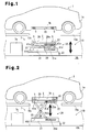
- a vehicle battery unit installation apparatus of each of the first and second embodiments and the modifications 1 and 2 installs a battery unit 3 in a vehicle body 1 a of an electric vehicle 1, and detaches the battery unit 3 from the vehicle body 1 a in a battery mounting station 10 (hereinafter, referred to as a station 10).
- a station 10 a battery mounting station 10
- the station 10 has an upper floor 10a and a lower floor 10b.
- the station 10 is formed with a communication opening 10c for communicating the upper floor 10a and the lower floor 10b.
- the electric vehicle 1 can be arranged on the upper floor 10a.
- the transfer apparatus 7 is arranged on the lower floor 10b.
- the electric vehicle 1 is formed with a mounting space 1b capable of mounting the battery unit 3 on the lower part of the vehicle body 1a.
- the vehicle body 1a is provided with side members 20 as a pair of frames, extending in the longitudinal direction of the vehicle body 1 a. The configuration of the side members 20 will be described later.
- the vehicle battery unit installation apparatus of the first embodiment includes striker devices 9, locking devices 5, and pins 11 and first solenoids 27b (see Fig. 7(A) and Fig. 7(B) ) that serve as lock releasing parts.
- the vehicle battery unit installation apparatus is provided with the four striker devices 9, the four locking devices 5, the four pins 11, and the four first solenoids 27b.
- each striker device 9 is provided in the vehicle body 1 a, and each locking device 5 is provided in the battery unit 3.
- the aforementioned side members 20 each have a pair of frame side walls 20a and 20b and a frame lower wall 20c that is connected to the lower ends of the frame side walls 20a and 20b and extends in the substantially horizontal direction, as shown in Fig. 4 .
- Each side member 20 has a vertical cross section formed in a substantially rectangular U-shape.
- a back plate 20d having a vertical cross section formed in a substantial L-shape is provided inside the side member 20, a back plate 20d having a vertical cross section formed in a substantial L-shape is provided.
- each striker device 9 has a base plate 90, and a striker 91.
- the base plate 90 has a base plate lower wall 90a extending substantially parallel to the frame lower wall 20c, and a base plate side wall 90b formed by bending and extending one end of the base plate lower wall 90a along the frame side wall 20a.
- the base plate 90 has a vertical cross section formed in a substantial L-shape.
- a recess 90c is formed on the substantial center of the base plate lower wall 90a.
- a plurality of bolt holes 90d are formed on each of the base plate lower wall 90a and the base plate side wall 90b.
- the striker 91 is made of steel and has a support part 91 a extending substantially parallel to the frame lower wall 20c, as shown in Fig. 4 . As shown in Fig. 4 , bending work is applied to both of the first end 91 b and the second end 91 c of the striker 91.
- the first end 91 b extends upward from the support part 91 a in the substantially vertical direction and thereafter extends parallel to the base plate lower wall 20c to be located in the recess 90c of the base plate lower wall 90a.
- the second end 91 c of the striker 91 extends upward in the substantially vertical direction along the base plate side wall 90b from the support part 91 a.
- the first end 91 b of the striker 91 is welded to the upper surface of the base plate lower wall 90a, namely, the base plate lower wall 90a in the recess 90c.
- the second end 91 c of the striker 91 is welded to the base plate side wall 90b.
- the striker 91 has both ends secured to the base plate 90 such that the support part 91 a is located below the side member 20.
- the base plate 90 is secured to the back plate 20d shown in Fig. 4 via the side member 20 with bolts 90e inserted into the respective bolt holes 90d. Consequently, the striker device 9 is secured to the side member 20 in a state where the base plate lower wall 90a and the base plate side wall 90b abut on the frame lower wall 20c and the frame side wall 20a, respectively.
- the two striker devices 9 are mounted on each of the side members 20 to be located in the mounting space 1 b shown in Fig. 1 .
- the two strikers 91 face each other in the longitudinal direction. Therefore, the support parts 91 a are capable of supporting the load of the battery unit 3 installed in the vehicle body 1 a, as shown in Fig. 2 .
- the number of the striker devices 9 to be mounted on the each of the side members 20 can be appropriately changed according to the size or the load of the battery unit 3.
- the side member 20 on the rear side of the sheet and the striker devices 9 mounted on this side member 20 are omitted.
- the battery unit 3 includes a rectangular box-like case 3a and a plurality of batteries (not shown in detail) housed in the case 3a.
- the case 3a is provided with connection terminals (not shown) capable of electrically connecting the vehicle body 1 a shown in Fig. 1 and the respective batteries.
- the shape of the case 3a can be appropriately changed according to the shape of the mounting space 1 b shown in Fig. 1 . This is also applicable to the modifications 1 and 2 described later.
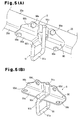
- each locking device 5 has a housing 13, a latch 15, a pawl 17, and a second solenoid 19.
- the second solenoid 19 is secured to a lock pin 25.
- each housing 13 is secured to the case 3a of the battery unit 3.
- the housing 13 has an entering opening 13b that is opened on an upper end and extends downward to enable the entering of the support part 91 a of the striker 91.
- the housing 13 has an insertion hole 13c that is opened from the lower end toward the inside of the housing 13 to enable the insertion of the pin 11.
- a guide part 13d for guiding the pin 11 is formed around the insertion hole 13c by applying bending work to the housing 13.
- the housing 13 is formed with three bolt holes 13e. The housing 13 is secured to the case 3a with bolts (not shown) inserted into the respective bolt holes 13e.
- first swing shaft 21 and a second swing shaft 23 are provided to protrude horizontally.
- the shaft center of the first swing shaft 21 is a first swing shaft center O1
- the shaft center of the second swing shaft 23 is a second swing shaft center 02.
- a recess 15c is formed on a part of the latch 15, and the latch 15 has a substantial U-shape.
- the upper side of the recess 15c is an upper pawl part 15a
- the lower side of the recess 15c is a lower pawl part 15b.
- the support part 91 a that enters the entering opening 13b of the housing 13 is configured to be housed in the recess 15c.
- an engaging surface 15d is formed on a side opposite to the recess 15c.
- the latch 15 is pivotally supported with respect to the first swing shaft 21 and can selectively swing in the direction A1 and the direction A2.
- the latch 15 is urged in the direction A2 by a coil spring (not shown).
- the latch 15 swings in the direction A1, thereby bringing into a locking state where the support part 91 a is locked in the entering opening 13b.
- the latch 15 swings in the direction A2, thereby bringing into a released state where the support part 91 a is released in the entering opening 13b.
- the latch 15 swings about the first swing shaft center O1, thereby enabling switching between the locking state and the released state.
- the latch 15 is arranged in the housing 13 to be located on the vertical line CL passing the centroid G in the cross section of the side members 20, in a state where the battery unit 3 is installed in the vehicle body 1 a.
- the members such as the first swing shaft 21 are omitted.
- the members are omitted.
- the pawl 17 is formed with a locking piece 17a and an operation piece 17b substantially orthogonal with each other and has a substantial L-shape.
- the pawl 17 is pivotally supported with respect to the second swing shaft 23 and can selectively swing in the direction B1 and the direction B2.
- the pawl 17 is urged in the direction B1 by a coil spring (not shown).
- the pawl 17 swings in the direction B1, thereby causing the locking piece 17a to move a first position where the swing of the latch 15 can be regulated.
- the pawl 17 swings in the direction B2, thereby causing the locking piece 17a to move a second position where the swing of the latch 15 can be allowed.
- the pawl 17 swings about the second swing shaft center 02, thereby enabling switching of the position of the locking piece 17a between the first position and the second position.
- Each second solenoid 19 is electrically connected to a controller 7a, described later, by a connection terminal (not shown) arranged on a contact surface of the case 3a and a placing table 27, in a state where the battery unit 3 is placed on the placing table 27.
- the electrical connection between the second solenoid 19 and the controller 7a is released by separating the placing table 27 from the battery unit 3.
- the second solenoid 19 is driven by the controller 7a, thereby enabling switching between a state where the lock pin 25 horizontally protrudes in the housing 13 and a state where the lock pin 25 is housed in the second solenoid 19.
- the lock pin 25 horizontally protrudes in the housing 13, so that the lock pin 25 can regulate the swing of the pawl 17.
- the lock pin 25 is housed in the second solenoid 19, so that the lock pin 25 can release the regulation of the swing of the pawl 17.
- Other configurations of the second solenoid 19 are similar to those of known solenoids, and therefore the detailed description of the configurations will be omitted.
- the transfer apparatus 7 includes a base part 33 secured on the lower floor 10b, the placing table 27, a lifting mechanism 36 provided between the base part 33 and the placing table 27. In the vicinity of the transfer apparatus 7, the controller 7a is arranged.
- the lifting mechanism 36 includes a lower holding member 31, a pair of a first link member 35 and a second link member 37, and an upper holding member 29.
- the lower holding member 31 is secured on the base part 33.
- the lower holding member 31 is formed with a pair of long holes 31 a extending horizontally.
- the upper holding member 29 is formed with a pair of long holes 29a extending horizontally.
- the first and second link members 35 and 37 are formed to have the same length and are pivotally coupled to each other at the central parts thereof by a coupling pin 39.
- the lower end of the first link member 35 is pivotally coupled to the lower holding member 31 by a coupling shaft 41 b.
- the lower end of second link member 37 is pivotal with respect to the lower holding member 31 and slidable in the long holes 31 a by a coupling shaft 41 d.
- the upper end of the second link member 37 is pivotally coupled to the upper holding member 29 by a coupling shaft 41 c.
- the upper end of the first link member 35 is pivotal with respect to the upper holding member 29 and slidable in the long holes 29a by a coupling shaft 41 a.
- the placing table 27 is secured to the upper holding member 29.
- a motor (not shown) and a gear train(not shown) capable of transmitting power to the coupling shaft 41 d by the motor is provided.
- the motor is electrically connected to the controller 7a.
- An electric direct-operated cylinder or a hydraulic cylinder can be employed in place of the motor.
- limit switches 28 are mounted at such positions as to abut on the housings 13 of the respective locking devices 5.
- the placing table 27 is mounted with the four limit switches 28.
- Each of the limit switches 28 is electrically connected to the controller 7a shown in Fig. 1 .
- Each limit switch 28 detects that the battery unit 3 and the placing table 27 abut on each other by being pressed down by the housing 13 of the corresponding locking device 5, thereby enabling transmission of a detection signal.
- pressure sensors capable of detecting the pressure of the battery unit 3 located on the placing table 27 may be employed.
- Each pin 11 is secured on the placing table 27 at such a position as to be inserted into the insertion hole 13c corresponding to the locking device 5 secured to the case 3a of the battery unit 3.
- each pin 11 vertically extends upward from the surface 27a of the placing table 27.
- Each pin 11 is connected to the first solenoid 27b provided in the placing table 27 corresponding to the pin 11.
- Each first solenoid 27b is electrically connected to the controller 7a shown in Fig. 1 .
- Each first solenoid 27b is driven on the basis of a detection signal of the corresponding limit switch 28 at the time of the removing of the battery unit 3.
- Each first solenoid 27b can change the corresponding pin 11 between the first length ⁇ shown in Fig. 7(A) and the second length ⁇ shown in Fig. 7(B) .
- electric direct-operated cylinders or hydraulic cylinders can be employed.
- Each pin 11 protrudes from the surface 27a of the placing table 27 by the first length ⁇ shown in Fig. 7(A) , so that the battery unit 3 on the placing table 27 can be positioned while the pin 11 is inserted into the corresponding insertion hole 13c (see Fig. 6 ). Additionally, each pin 11 protrudes from the surface 27a of the placing table 27 by the second length ⁇ shown in Fig. 7(B) , so that the pin 11 abuts on the pawl 17 shown in Fig. 6 to cause the pawl 17 to swing from the direction B1 to the direction B2, namely, the position of the locking piece 17a can be made swing from the first position to the second position.
- the battery unit 3 is installed in the vehicle body 1 a and detached from the vehicle body 1 a, as described below.
- the electric vehicle 1 is arranged at a predetermined position of the upper floor 10a of the station 10. At this time, the position of the electric vehicle 1 is adjusted such that the mounting space 1 b is located right above the communication opening 10c, namely, right above the transfer apparatus 7. The electric vehicle 1 is not mounted with the battery unit 3 in the mounting space 1 b.
- each pin 11 protrudes from the surface 27a of the placing table 27 by the first length ⁇ .
- each pin 11 is inserted into the corresponding insertion hole 13c via the corresponding guide part 13d, as shown in Fig. 8 . Therefore, the battery unit 3 is positioned on the placing table 27.
- Each lock pin 25 is housed in the corresponding second solenoid 19, and the pawl 17 is released from the regulation of its swinging motion.
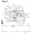
- the pawls 17 swing in the direction B1 by the urging force of the coil springs, and the locking pieces 17a each move from the second position to the first position (see the broken arrow in Fig. 10 ), as shown in Fig. 10 . Therefore, the locking pieces 17a are engaged with the engaging surfaces 15d of the latches 15. Thus, the latches 15 are brought into a locking state, to lock the support parts 91 a in the recesses 15c. At this time, as shown in Fig.
- the latches 15 each lock the support part 91 a on the vertical line CL passing the centroid G in the cross section of the side member 20, namely, right below the frame lower wall 20c.
- the batteries in the battery unit 3 and the electric vehicle 1 are simultaneously electrically connected to each other.
- the controller 7a drives the second solenoids 19 to protrude the lock pins 25 in the housing 13, as shown in Fig. 10 . Consequently, the operation pieces 17b of the pawls 17 and the lock pins 25 abut on each other, and the swinging of the pawls 17 from the direction B1 to the direction B2 is secured by the lock pins 25. That is, the locking pieces 17a regulate the movement to the second position.
- the lock pins 25 complete to secure the pawls 17, and the pawls 17 complete to secure the latches 15.
- the controller 7a lowers the placing table 27 (see the solid arrow in Fig. 11 ), and the pins 11 are pulled out from the inside of the insertion holes 13c. Consequently, the locking devices 5 complete to secure the support parts 91 a, and installation of the battery unit 3 in the mounting space 1 b is completed.
- the transfer apparatus 7 lifts the battery unit 3 up to the mounting space 1 b, so that the battery unit 3 can be installed in the vehicle body 1 a.
- the pawls 17 secure the swing of the latches 15 in the locking state, and therefore each locking device 5 reliably secures the corresponding support part 91 a.
- the latches 15 are located below the side members 20 as shown in Fig. 4 . Therefore, in the vehicle battery unit installation apparatus, when the battery unit 3 is installed in the vehicle body 1 a, the load (see the white arrow in Fig. 4 ) of the battery unit 3 acts only on the side members 20. Furthermore, the latches 15 each are located on the vertical line CL passing the centroid G in the cross section of the side members 20, so that only the vertically downward load of the battery unit 3 acts on the centroid G being the center of the strength of each side member 20.
- the battery unit 3 can be reliably installed in the vehicle body 1 a.
- description will be made by contrast with a vehicle battery mounting apparatus of a comparative example.
- striker devices 9a are mounted with a battery unit 3, and locking devices 5 are mounted on side members 20.
- Each of the striker devices 9a has a base plate 92 and a striker 93.
- the striker 93 has a support part 93a substantially parallel to a frame lower wall 20c. Substantially vertical bending work is applied to the striker 93 twice from the support part 93a toward a first end 93b.
- the striker 93 has a substantial U-shape.
- the first end 93b and a second end 93c of the striker 93 are welded to the base plate 92, so that the striker 93 is secured to the base plate 92.
- the base plate 92 is secured to a case 3a via a bolt 90e.
- the locking device 5 is secured to a back plate 20d by bolts 90e, to abut on the frame side wall 20b.
- the strength of each side member 20 needs to be increased by increasing the place thickness of each side member 20, or further providing a reinforcing part on the side member 20.
- the weight of the vehicle battery unit installation apparatus of the comparative example is greater than that of the vehicle battery unit mounting apparatus of the first embodiment.
- the electric vehicle 1 is arranged at a predetermined position of the upper floor 10a of the station 10. Also at this time, the position of the electric vehicle 1 is adjusted such that the mounting space 1 b is located right above the communication opening 10c, namely, right above the transfer apparatus 7. The electric vehicle 1 is mounted with the battery unit 3 in the mounting space 1 b.
- each pin 11 protrudes from the surface 27a of the placing table 27 by the first length ⁇ .
- the controller 7a lifts the placing table 27, as shown in Fig. 13 . Then, while each pin 11a on the placing table 27 is inserted into the corresponding insertion hole 13c, the placing table 27, and the battery unit 3 and the locking devices 5 abut on each other. At this time, each pin 11 is inserted into the corresponding insertion hole 13c while being guided by the corresponding guide part 13d, and therefore the placing table 27 is positioned with respect to the battery unit 3. Additionally, the battery unit 3 and the placing table 27 come into contact with each other, so that the second solenoids 19 and the controller 7a are electrically connected to each other.
- each second solenoid 19 is driven, so that the corresponding lock pin 25 is housed in the second solenoid 19.
- the controller 7a drives each first solenoid 27b. Consequently, the pin 11 protrudes from the surface 27a of the placing table 27 by the second length ⁇ .
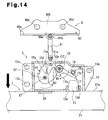
- the operation piece 17b of the pawl 17 is pressed by the pin 11 protruding by the second length ⁇ , so that the pawl 17 swings in the direction B2 (see the broken arrow in Fig.
- the placing table 27 is lowered, thereby moving the battery unit 3 downward from the inside of the mounting space 1b (see the solid arrow in Fig. 14 ). Consequently, the upper pawl parts 15a of the latches 15 are pressed by the support parts 91 a and are swung in the direction A2 with urging force of the coil springs, thereby bringing the latches 15 into a released state. Therefore, the support parts 91 a relatively move in such a direction as to separate from the entering openings 13b. Thus, the securing of the support parts 91 a by the locking devices 5 is released, and the detaching of the battery unit 3 from the vehicle body 1 a is completed. At this time, electrical connection between the batteries in the battery unit 3 and the electric vehicle 1 is simultaneously released.
- the controller 7a drives the first solenoids 27b, so that the pins 11 are moved to protrude by the first length ⁇ . Consequently, the pressing by the pins 11 to the operation pieces 17b are released. Therefore, by the urging force of the coil springs, the pawls 17 are swung in the direction B1, and the locking pieces 17a move from the second position to the first position. Thereafter, the battery unit 3 completely detached moves from the placing table 27. The protruding length of each pin 11 is changed from the second length ⁇ to the first length ⁇ before the battery unit 3 moves from the placing table 27, so that the damage of the pins 11 can be prevented.
- the battery unit 3 can be reliably installed in the vehicle body 1 a, and the battery unit 3 installed in the vehicle body 1 a can be easily detached.
- each striker device 9 is firmly secured to the corresponding side member 20, and the aforementioned load of the striker device 9 can be suitably shared by the side member 20.
- each striker 91 The ends of each striker 91 are secured to the base plate lower wall 90a and the base plate side wall 90b, and hence in the vehicle battery unit installation apparatus, the ends of the support part 91 a are reliably supported by the base plate 90.
- the first end 91 b of the striker 91 is secured to the base plate lower wall 90a in a state of being placed in the recess 90c of the upper surface of the base plate lower wall 90a, and hence one end of the support part 91 a is reliably supported in the recess 90c of the upper surface of the base plate lower wall 90a.
- the durability of each striker device 9 is improved, and reliability of the installation of the battery unit 3 in the vehicle body 1 a is improved.
- each base plate 90 is secured to the side member 20 by the plurality of bolts 90e.
- the side member 20 is provided with the back plate 20d joined with the base plate 90 by the bolts 90e. Therefore, in the vehicle battery unit installation apparatus, each striker device 9 can be easily secured to the side member 20. Additionally, the necessary part of the side member 20 is reinforced by the back plate 20d, and hence the side member 20 can be effectively reinforced.
- striker devices 9 each have a base plate 94 and a striker 95.
- the base plate 94 has a base plate lower wall 94a extending substantially parallel to a frame lower wall 20c, and a base plate side wall 94b formed by bending and extending an end of the base plate lower wall 94a along a frame side wall 20a. Additionally, the base plate lower wall 94a has a tip end to which bending work is applied and is formed with a fitting hole 94c.
- Other configurations of the base plate 94 are similar to those of the base plate 90.
- Each striker 95 has a support part 95a extending substantially parallel to the frame lower wall 20c. Additionally, the striker 95 has a first end 95b and a second end 95c extending upward from the support part 95a in the substantially vertical direction. Then, after the first end 95b of the striker 95 is inserted into the fitting hole 94c, the end surface 95d of the first end 95b is crushed, so that the first end 95b is secured to the base plate lower wall 94a. On the other hand, the second end 95c of the striker 95 is welded to the base plate side wall 94b. Consequently, in the striker 95, the ends of the striker 95 are secured to the base plate 94 such that the support part 95a is located below the side members 20.
- Other configurations of the vehicle battery unit installation apparatus are similar to those of the vehicle battery unit installation apparatus of the first embodiment, the same configurations are denoted by the same reference numerals, and the detailed description thereof will be omitted.
- the load of the battery unit 3 at the time of installation is shared by the ends of the support parts 95a to be transmitted to the base plates 94, and supported by the side members 20. Therefore, also in the vehicle battery unit installation apparatus, the battery unit 3 can be firmly installed in the vehicle body 1 a.
- Other working effects are similar to those of the vehicle battery unit installation apparatus of the first embodiment.
- a battery unit 3 has a case 30a.
- the case 30a is formed with four recesses 30b.
- Locking devices 5 are secured to the case 30a in a state where being arranged in the corresponding recesses 30b.
- the locking devices 5 do not protrude from the battery unit 3, so that the mounting space 1 b can be downsized.
- Other working effects are similar to those of the vehicle battery unit installation apparatus of the first embodiment.
- a battery unit 3 has a case 300a.
- the case 300a is formed with four recesses 300b and is formed to protrude in the height direction.
- Each locking device 5 is secured to the case 300a in a state of being arranged in the corresponding recess 300b.
- the battery unit 3 having the case 300 enables the electric vehicle 1 to travel a longer distance.
- the case 300a is formed to have a reduced length in the longitudinal direction or the width direction, so that the length of the battery unit 3 in the longitudinal direction or the width direction can be reduced without reduction in the number of batteries to be housed. Therefore, with the case 300a, the degree of freedom of design in the vehicle body 1 a can be improved. Other working effects are similar to those of the vehicle battery unit installation apparatuses of the first embodiment and the modification 1.
- the present invention is described based on the first and second embodiments, and the modifications 1 and 2.
- the present invention is not limited to the first and second embodiments, and the modifications 1 and 2, and, of course, can be appropriately modified without departing from the spirit thereof.
- a detection unit capable of detecting the locking state and the released state of each latch 15 to transmit a detection signal can be provided.
- the controller 7a may drive each second solenoid 19 to protrude or house the corresponding lock pin 25, on the basis of the detection signal. In this case, misoperation is prevented at the time of the securing and detaching of the battery unit 3.
- the mounting space 1b capable of mounting the battery unit 3 is formed in the electric vehicle 1.
- the present invention is not limited to such a shape. Any electric vehicle capable of installing the battery unit on the lower surface of the vehicle body 1 a may be employed.
- each side member 20 is formed in a rectangle where the frame lower wall 20c extends horizontally.
- the frame lower wall 20c may be formed to incline with respect to the width direction of the vehicle body 1 a, or the side member may have a polygon.
- the connection portions of the frame lower wall 20c, and the frame side walls 20a and 20b may be chamfered. In a case where the connection portions are chamfered, the base plate 90 similarly chamfered can be employed.
- each back plate 20d is arranged inside the side member 20.
- the back plate 20d may be arranged outside the side member 20. In this case, the base plate 90 and the side member 20 are secured by the bolts 90e via the back plate 20d.
- each striker 91 is welded to the upper surface of the base plate lower wall 90a.
- the first end 91 b and the second end 91 c of the striker 91 may be welded to the upper surface of the base plate lower wall 90a.
- the second end 91 c of the striker 91 is preferably located on the upper surface of the base plate lower wall 90a by providing a notch in the base plate side wall 90b, or including only the base plate lower wall 90a in the base plate 90.
Landscapes
- Engineering & Computer Science (AREA)
- Mechanical Engineering (AREA)
- Transportation (AREA)
- Chemical & Material Sciences (AREA)
- Combustion & Propulsion (AREA)
- Power Engineering (AREA)
- Arrangement Or Mounting Of Propulsion Units For Vehicles (AREA)
- Battery Mounting, Suspending (AREA)
Applications Claiming Priority (2)
| Application Number | Priority Date | Filing Date | Title |
|---|---|---|---|
| JP2011136803A JP5141795B2 (ja) | 2011-06-20 | 2011-06-20 | 車両用バッテリユニット装着装置 |
| PCT/JP2012/064529 WO2012176619A1 (ja) | 2011-06-20 | 2012-06-06 | 車両用バッテリユニット装着装置 |
Publications (2)
| Publication Number | Publication Date |
|---|---|
| EP2722211A1 true EP2722211A1 (de) | 2014-04-23 |
| EP2722211A4 EP2722211A4 (de) | 2015-04-15 |
Family
ID=47422459
Family Applications (1)
| Application Number | Title | Priority Date | Filing Date |
|---|---|---|---|
| EP12802669.7A Withdrawn EP2722211A4 (de) | 2011-06-20 | 2012-06-06 | Vorrichtung zur installation einer fahrzeugbatterieeinheit |
Country Status (5)
| Country | Link |
|---|---|
| US (1) | US9573453B2 (de) |
| EP (1) | EP2722211A4 (de) |
| JP (1) | JP5141795B2 (de) |
| CN (1) | CN103619623B (de) |
| WO (1) | WO2012176619A1 (de) |
Cited By (3)
| Publication number | Priority date | Publication date | Assignee | Title |
|---|---|---|---|---|
| WO2016198552A1 (en) * | 2015-06-10 | 2016-12-15 | Battswap, Inc. | Battery exchange system |
| WO2019075017A1 (en) * | 2017-10-12 | 2019-04-18 | Inevit Llc | CLIP-BASED FIXING FOR A COMPARTMENT COVER FOR BATTERY MODULE |
| EP3733434A4 (de) * | 2017-12-29 | 2021-08-04 | Shanghai Dianba New Energy Technology Co., Ltd. | Schlossmechanismus, schlosssystem, schnellwechselklammeranordnung und elektronisches fahrzeug |
Families Citing this family (32)
| Publication number | Priority date | Publication date | Assignee | Title |
|---|---|---|---|---|
| FR2954592B1 (fr) * | 2009-12-21 | 2012-01-06 | Renault Sa | Procede et syteme de montage ou demontage d'une batterie d'un vehicule automobile. |
| JP2013006568A (ja) * | 2011-06-27 | 2013-01-10 | Toyota Industries Corp | 移載装置 |
| EP2614982A3 (de) * | 2012-01-11 | 2017-11-01 | Tata Technologies Pte Ltd | Austauschbares, konfigurierbares und strukturiertes Batteriepack für Elektrofahrzeuge |
| JP6036315B2 (ja) * | 2013-01-11 | 2016-11-30 | 株式会社豊田自動織機 | ロック構造 |
| JP6036667B2 (ja) * | 2013-12-04 | 2016-11-30 | 株式会社豊田自動織機 | 車両用バッテリユニット保持装置 |
| DE102014100334A1 (de) * | 2014-01-14 | 2015-07-16 | Dr. Ing. H.C. F. Porsche Aktiengesellschaft | Verfahren und Vorrichtung zum Wechsel einer Batterie eines Hybrid- oder Elektrofahrzeugs |
| DE102014012463B4 (de) | 2014-08-21 | 2020-06-04 | Diehl Defence Gmbh & Co. Kg | Vorrichtung zur Unterflur-Montage eines Generators an einem Kraftfahrzeug |
| CN104385892B (zh) * | 2014-09-18 | 2017-02-01 | 浙江吉利控股集团有限公司 | 一种电动车辆 |
| CN107249958B (zh) * | 2015-02-27 | 2022-04-29 | 川崎重工业株式会社 | 安装件、安装单元、以及铁道车辆 |
| CN106080159B (zh) * | 2016-05-25 | 2019-03-22 | 上海蔚来汽车有限公司 | 锁体组件、动力电池、其锁止机构及使用方法、交通工具 |
| CN114148212A (zh) * | 2016-11-21 | 2022-03-08 | 上海电巴新能源科技有限公司 | 锁止装置及电动汽车 |
| DE102016123553A1 (de) * | 2016-12-06 | 2018-06-07 | Dr. Ing. H.C. F. Porsche Aktiengesellschaft | Fahrzeugkarosserie für ein elektrisch angetriebenes Fahrzeug |
| CN111645562A (zh) * | 2016-12-30 | 2020-09-11 | 上海电巴新能源科技有限公司 | 换电平台、电池安装部及换电移动装置 |
| KR102016349B1 (ko) * | 2017-07-06 | 2019-08-30 | 주식회사 성우하이텍 | 전기자동차용 배터리 케이스의 체결장치 |
| JP6946995B2 (ja) * | 2017-12-13 | 2021-10-13 | トヨタ自動車株式会社 | 車両 |
| CN114161987B (zh) * | 2017-12-29 | 2023-12-29 | 上海电巴新能源科技有限公司 | 换电设备解锁装置、换电设备及电池箱快速换电系统 |
| CN111933851B (zh) * | 2017-12-29 | 2023-01-31 | 上海电巴新能源科技有限公司 | 支撑装置、电池固定座及电动车 |
| CN110203071B (zh) * | 2018-02-28 | 2022-05-06 | 奥动新能源汽车科技有限公司 | 电动汽车及其电池箱检测装置 |
| CN108382372A (zh) * | 2018-04-09 | 2018-08-10 | 广东技术师范学院 | 一种电动车快速换电系统 |
| JP7163059B2 (ja) * | 2018-04-27 | 2022-10-31 | メルセデス・ベンツ グループ アクチェンゲゼルシャフト | 車両用バッテリハウジング、車両用バッテリパック、及び電動車両 |
| NL2020843B1 (en) * | 2018-04-30 | 2019-11-07 | R U Eng & Detachering B V | Battery exchange system and method |
| CN111048706B (zh) * | 2018-10-12 | 2022-10-21 | 奥动新能源汽车科技有限公司 | 车载动力电池组件以及新能源车 |
| CN111114372A (zh) * | 2018-11-01 | 2020-05-08 | 北京新能源汽车股份有限公司 | 锁止结构、电池包、电池锁止装置、车辆以及换电方法 |
| CN111332151B (zh) * | 2018-12-03 | 2021-05-14 | 浙江吉智新能源汽车科技有限公司 | 一种电池快换装置、电动汽车及快换方法 |
| CN109910583A (zh) * | 2019-03-27 | 2019-06-21 | 上海玖行能源科技有限公司 | 一种电池包斜面锁止机构 |
| CN112140859B (zh) * | 2019-06-27 | 2024-07-02 | 奥动新能源汽车科技有限公司 | 快换支架组件及电动汽车 |
| US11325453B2 (en) | 2019-12-18 | 2022-05-10 | Toyota Motor Engineering & Manufacturing North America, Inc. | Battery mounting bracket for heavy duty vehicle |
| US11891119B2 (en) * | 2020-05-27 | 2024-02-06 | Eve Power Co., Ltd. | Chassis assembly and vehicle |
| CN114194063B (zh) * | 2020-09-17 | 2024-07-02 | 奥动新能源汽车科技有限公司 | 用于水平挂接电池包的电池包安装部及其电动汽车 |
| CN215154062U (zh) * | 2021-05-31 | 2021-12-14 | 浙江康迪智能换电科技有限公司 | 一种电动汽车换电定位举升机构 |
| CN217730194U (zh) * | 2021-11-30 | 2022-11-04 | 奥动新能源汽车科技有限公司 | 适用多规格电池包的电动汽车 |
| CN114520392B (zh) * | 2022-03-03 | 2024-04-12 | 中国第一汽车股份有限公司 | 电池快换装置及具有其的车辆 |
Citations (1)
| Publication number | Priority date | Publication date | Assignee | Title |
|---|---|---|---|---|
| FR2943970A3 (fr) * | 2009-04-03 | 2010-10-08 | Renault Sas | Dispositif de verrouillage de la position d'un moyen de stockage d'energie electrique |
Family Cites Families (38)
| Publication number | Priority date | Publication date | Assignee | Title |
|---|---|---|---|---|
| US3572062A (en) * | 1969-09-22 | 1971-03-23 | S & C Electric Co | Tamper proof locking means using a padlock |
| JPS53700Y2 (de) * | 1973-10-23 | 1978-01-11 | ||
| DE3436318C2 (de) * | 1984-10-04 | 1986-07-24 | Daimler-Benz Ag, 7000 Stuttgart | Schloß, insbesondere für schwenkbare Hauben, Klappen oder dergleichen von Kraftwagen |
| DE4229687A1 (de) * | 1992-09-05 | 1994-03-10 | Dieter Kitto Werkzeug Und Masc | Batteriewechselstation für elektrisch angetriebene Kraftfahrzeuge |
| US5529356A (en) * | 1994-05-25 | 1996-06-25 | Atoma International Inc. | Vehicle door striker with improved end portion |
| JP3293355B2 (ja) * | 1994-09-06 | 2002-06-17 | スズキ株式会社 | 自動車のフード構造 |
| JP3201969B2 (ja) * | 1997-03-07 | 2001-08-27 | 三井金属鉱業株式会社 | 車両ドアロック装置における衝突時の開扉防止装置 |
| US6000737A (en) * | 1997-09-17 | 1999-12-14 | Atoma International Corp. | Loop striker |
| JP3957874B2 (ja) * | 1998-05-13 | 2007-08-15 | 本田技研工業株式会社 | 自動車のボンネット |
| US6547291B1 (en) * | 2001-01-26 | 2003-04-15 | Midway Products Group, Inc. | Latch assembly for vehicle hood |
| JP3941422B2 (ja) * | 2001-06-06 | 2007-07-04 | 株式会社豊田自動織機 | バッテリ装置およびその取り付け構造 |
| JP2003118397A (ja) * | 2001-10-10 | 2003-04-23 | Toyota Industries Corp | バッテリ装置の取り付け構造 |
| JP2006123658A (ja) * | 2004-10-27 | 2006-05-18 | Mitsubishi Fuso Truck & Bus Corp | 車両の電子機器取付構造 |
| JP4383327B2 (ja) * | 2004-11-30 | 2009-12-16 | 本田技研工業株式会社 | 燃料電池自動車およびガス燃料自動車の放出管取付構造 |
| FR2880476A1 (fr) | 2005-01-04 | 2006-07-07 | Joel Henry Marcel Enault | Coffre a batterie pour vehicule electrique |
| JP4385020B2 (ja) * | 2005-06-02 | 2009-12-16 | 本田技研工業株式会社 | 車両用電源装置 |
| DE202006019165U1 (de) * | 2006-12-20 | 2008-05-08 | S-Fasteners Gmbh | Anordnung mit einem Verriegelungs-Element für einen Verriegelungshaken |
| JP4420017B2 (ja) * | 2006-12-28 | 2010-02-24 | 三菱自動車工業株式会社 | 電気自動車のバッテリ搭載構造 |
| US7854452B2 (en) * | 2007-03-23 | 2010-12-21 | Nishio Seimitsu Kabushiki Kaisha | Engagement fitting and manufacturing method of engagement fitting |
| JP5015709B2 (ja) * | 2007-09-24 | 2012-08-29 | 株式会社アンセイ | 車両用開閉体のストライカ及びその製造方法 |
| JP5151363B2 (ja) * | 2007-09-28 | 2013-02-27 | 三菱自動車工業株式会社 | 電気自動車用バッテリケース |
| JP5040566B2 (ja) | 2007-09-28 | 2012-10-03 | 三菱自動車工業株式会社 | 電気自動車のバッテリー固定構造 |
| US7631928B2 (en) * | 2007-11-09 | 2009-12-15 | Toyota Motor Engineering & Manufacturing North America, Inc. | Vehicle hood reinforcement structures |
| JP5091707B2 (ja) * | 2008-02-14 | 2012-12-05 | 株式会社エンプラス | 偏光状態変換方法、偏光状態変換装置並びに液晶ディスプレイ |
| US8006793B2 (en) * | 2008-09-19 | 2011-08-30 | Better Place GmbH | Electric vehicle battery system |
| JP4479844B2 (ja) * | 2008-09-30 | 2010-06-09 | トヨタ自動車株式会社 | 車両用フード構造 |
| JP2010184621A (ja) | 2009-02-13 | 2010-08-26 | Nissan Motor Co Ltd | バッテリ固定装置およびバッテリ交換装置 |
| EP2269879A1 (de) * | 2009-03-22 | 2011-01-05 | Oliver Vogt | Auswechselbarer Energiespeicher für ein Kraftfahrzeug |
| JP2010284984A (ja) * | 2009-06-09 | 2010-12-24 | Fuji Heavy Ind Ltd | 車両用バッテリ搭載構造 |
| DE102009035394A1 (de) * | 2009-07-30 | 2011-02-03 | Jungheinrich Aktiengesellschaft | Verriegelungsvorrichtung für einen Batterieblock für ein Flurförderzeug |
| US8795876B2 (en) * | 2009-09-24 | 2014-08-05 | Alte Powertrain Technologies, Inc. | Device for making rapid connections and disconnections between high voltage battery modules and other motor vehicle systems |
| JP5136539B2 (ja) | 2009-11-06 | 2013-02-06 | 株式会社豊田自動織機 | 電気自動車のバッテリ搭載構造 |
| US8801052B2 (en) * | 2010-01-11 | 2014-08-12 | Deere & Company | Hood latch |
| US7913788B1 (en) * | 2010-02-09 | 2011-03-29 | Gm Global Technology Operations, Llc | Integrated energy storage and rear suspension assembly |
| JP5140893B2 (ja) * | 2010-06-09 | 2013-02-13 | 三井金属アクト株式会社 | ラッチ装置 |
| US8292015B2 (en) * | 2010-07-21 | 2012-10-23 | Caterpillar Global Mining America Llc | Battery-powered mining vehicle |
| US8925983B2 (en) * | 2011-06-20 | 2015-01-06 | Kabushiki Kaisha Toyota Jidoshokki | Locking apparatus for vehicle |
| JP6020958B2 (ja) * | 2012-07-13 | 2016-11-02 | 三菱自動車工業株式会社 | 電池パックトレー |
-
2011
- 2011-06-20 JP JP2011136803A patent/JP5141795B2/ja not_active Expired - Fee Related
-
2012
- 2012-06-06 CN CN201280029986.4A patent/CN103619623B/zh active Active
- 2012-06-06 US US14/127,565 patent/US9573453B2/en not_active Expired - Fee Related
- 2012-06-06 WO PCT/JP2012/064529 patent/WO2012176619A1/ja active Application Filing
- 2012-06-06 EP EP12802669.7A patent/EP2722211A4/de not_active Withdrawn
Patent Citations (1)
| Publication number | Priority date | Publication date | Assignee | Title |
|---|---|---|---|---|
| FR2943970A3 (fr) * | 2009-04-03 | 2010-10-08 | Renault Sas | Dispositif de verrouillage de la position d'un moyen de stockage d'energie electrique |
Non-Patent Citations (1)
| Title |
|---|
| See also references of WO2012176619A1 * |
Cited By (6)
| Publication number | Priority date | Publication date | Assignee | Title |
|---|---|---|---|---|
| WO2016198552A1 (en) * | 2015-06-10 | 2016-12-15 | Battswap, Inc. | Battery exchange system |
| WO2019075017A1 (en) * | 2017-10-12 | 2019-04-18 | Inevit Llc | CLIP-BASED FIXING FOR A COMPARTMENT COVER FOR BATTERY MODULE |
| EP3733434A4 (de) * | 2017-12-29 | 2021-08-04 | Shanghai Dianba New Energy Technology Co., Ltd. | Schlossmechanismus, schlosssystem, schnellwechselklammeranordnung und elektronisches fahrzeug |
| KR20210124508A (ko) * | 2017-12-29 | 2021-10-14 | 상하이 디안바 뉴 에너지 테크놀러지 코., 엘티디. | 잠금 메커니즘, 잠금 시스템, 퀵 교체 브래킷 어셈블리 및 전기 자동차 |
| US11359410B2 (en) | 2017-12-29 | 2022-06-14 | Shanghai Dianba New Energy Technology Co., Ltd. | Lock mechanism, lock system, quick exchange bracket assembly and electronic vehicle |
| AU2018393463B2 (en) * | 2017-12-29 | 2024-01-25 | Aulton New Energy Automotive Technology Group | Lock mechanism, lock system, quick exchange bracket assembly and electronic vehicle |
Also Published As
| Publication number | Publication date |
|---|---|
| WO2012176619A1 (ja) | 2012-12-27 |
| EP2722211A4 (de) | 2015-04-15 |
| US20140165354A1 (en) | 2014-06-19 |
| JP2013001336A (ja) | 2013-01-07 |
| CN103619623A (zh) | 2014-03-05 |
| JP5141795B2 (ja) | 2013-02-13 |
| US9573453B2 (en) | 2017-02-21 |
| CN103619623B (zh) | 2016-04-20 |
Similar Documents
| Publication | Publication Date | Title |
|---|---|---|
| EP2722211A1 (de) | Vorrichtung zur installation einer fahrzeugbatterieeinheit | |
| JP2013001335A (ja) | 車両用バッテリユニット装着装置 | |
| EP2602162A2 (de) | Batteriemontagevorrichtung für elektrische Fahrzeuge, Batterieeinheitsübertragungsvorrichtung für elektrische Fahrzeuge und Verfahren zur Montage der Batterieeinheit | |
| JP2013006568A (ja) | 移載装置 | |
| WO2023098723A1 (zh) | 电动车辆及快换组件 | |
| CN105895841A (zh) | 电池包固定结构及电池包更换装置 | |
| JP2013028324A (ja) | 車両用ロック装置 | |
| JP5754745B2 (ja) | 自動車を駆動するモータに電力供給するバッテリを交換するためのデバイス | |
| JP2018154190A (ja) | バッテリパック交換装置 | |
| CN113415144A (zh) | 电池包锁止机构、托架总成、电动汽车及电池包的锁止方法 | |
| WO2012160557A2 (en) | Latching mechanism for a vehicle's battery pack | |
| CN112389917B (zh) | 换电方法 | |
| JP2011063944A (ja) | 充電機能を備えた機械式駐車装置 | |
| CN113479050A (zh) | 电池包锁止机构、托架总成、电动汽车及电池包的锁止方法 | |
| CN107848388B (zh) | 电动车辆 | |
| CN205509143U (zh) | 充电枪的锁止装置 | |
| CN113479048A (zh) | 锁止装置、托架总成、电动汽车及电池箱的锁止方法 | |
| CN215284331U (zh) | 电池包锁止机构、托架总成及电动汽车 | |
| CN205790104U (zh) | 电池包固定结构及电池包更换装置 | |
| CN211688081U (zh) | 换电移动装置 | |
| CN218505679U (zh) | 电动卡车换电系统 | |
| CN218367370U (zh) | 电动汽车的电池包锁止机构、快换支架及电动矿用卡车 | |
| CN212332350U (zh) | 电池包锁定装置、托架总成及电动汽车 | |
| JP2003226142A (ja) | 電気自動車のバッテリ交換方法および電気自動車のバッテリ搭載構造 | |
| CN215284332U (zh) | 电池包锁止机构、托架总成及电动汽车 |
Legal Events
| Date | Code | Title | Description |
|---|---|---|---|
| PUAI | Public reference made under article 153(3) epc to a published international application that has entered the european phase |
Free format text: ORIGINAL CODE: 0009012 |
|
| 17P | Request for examination filed |
Effective date: 20131217 |
|
| AK | Designated contracting states |
Kind code of ref document: A1 Designated state(s): AL AT BE BG CH CY CZ DE DK EE ES FI FR GB GR HR HU IE IS IT LI LT LU LV MC MK MT NL NO PL PT RO RS SE SI SK SM TR |
|
| DAX | Request for extension of the european patent (deleted) | ||
| RA4 | Supplementary search report drawn up and despatched (corrected) |
Effective date: 20150312 |
|
| RIC1 | Information provided on ipc code assigned before grant |
Ipc: B60L 11/18 20060101ALI20150306BHEP Ipc: B60K 1/04 20060101AFI20150306BHEP |
|
| GRAP | Despatch of communication of intention to grant a patent |
Free format text: ORIGINAL CODE: EPIDOSNIGR1 |
|
| INTG | Intention to grant announced |
Effective date: 20170330 |
|
| GRAS | Grant fee paid |
Free format text: ORIGINAL CODE: EPIDOSNIGR3 |
|
| STAA | Information on the status of an ep patent application or granted ep patent |
Free format text: STATUS: THE APPLICATION IS DEEMED TO BE WITHDRAWN |
|
| 18D | Application deemed to be withdrawn |
Effective date: 20180103 |