EP2646384B1 - Verfahren zur herstellung von hochdichten lochanordnungen in glas - Google Patents
Verfahren zur herstellung von hochdichten lochanordnungen in glas Download PDFInfo
- Publication number
- EP2646384B1 EP2646384B1 EP11799537.3A EP11799537A EP2646384B1 EP 2646384 B1 EP2646384 B1 EP 2646384B1 EP 11799537 A EP11799537 A EP 11799537A EP 2646384 B1 EP2646384 B1 EP 2646384B1
- Authority
- EP
- European Patent Office
- Prior art keywords
- glass
- range
- irradiating
- holes
- front surface
- Prior art date
- Legal status (The legal status is an assumption and is not a legal conclusion. Google has not performed a legal analysis and makes no representation as to the accuracy of the status listed.)
- Not-in-force
Links
Images


Classifications
-
- C—CHEMISTRY; METALLURGY
- C03—GLASS; MINERAL OR SLAG WOOL
- C03B—MANUFACTURE, SHAPING, OR SUPPLEMENTARY PROCESSES
- C03B33/00—Severing cooled glass
- C03B33/08—Severing cooled glass by fusing, i.e. by melting through the glass
- C03B33/082—Severing cooled glass by fusing, i.e. by melting through the glass using a focussed radiation beam, e.g. laser
-
- B—PERFORMING OPERATIONS; TRANSPORTING
- B23—MACHINE TOOLS; METAL-WORKING NOT OTHERWISE PROVIDED FOR
- B23K—SOLDERING OR UNSOLDERING; WELDING; CLADDING OR PLATING BY SOLDERING OR WELDING; CUTTING BY APPLYING HEAT LOCALLY, e.g. FLAME CUTTING; WORKING BY LASER BEAM
- B23K26/00—Working by laser beam, e.g. welding, cutting or boring
- B23K26/36—Removing material
- B23K26/38—Removing material by boring or cutting
- B23K26/382—Removing material by boring or cutting by boring
- B23K26/389—Removing material by boring or cutting by boring of fluid openings, e.g. nozzles, jets
-
- H—ELECTRICITY
- H10—SEMICONDUCTOR DEVICES; ELECTRIC SOLID-STATE DEVICES NOT OTHERWISE PROVIDED FOR
- H10W—GENERIC PACKAGES, INTERCONNECTIONS, CONNECTORS OR OTHER CONSTRUCTIONAL DETAILS OF DEVICES COVERED BY CLASS H10
- H10W70/00—Package substrates; Interposers; Redistribution layers [RDL]
- H10W70/60—Insulating or insulated package substrates; Interposers; Redistribution layers
- H10W70/62—Insulating or insulated package substrates; Interposers; Redistribution layers characterised by their interconnections
- H10W70/63—Vias, e.g. via plugs
- H10W70/635—Through-vias
-
- C—CHEMISTRY; METALLURGY
- C03—GLASS; MINERAL OR SLAG WOOL
- C03C—CHEMICAL COMPOSITION OF GLASSES, GLAZES OR VITREOUS ENAMELS; SURFACE TREATMENT OF GLASS; SURFACE TREATMENT OF FIBRES OR FILAMENTS MADE FROM GLASS, MINERALS OR SLAGS; JOINING GLASS TO GLASS OR OTHER MATERIALS
- C03C23/00—Other surface treatment of glass not in the form of fibres or filaments
-
- B—PERFORMING OPERATIONS; TRANSPORTING
- B23—MACHINE TOOLS; METAL-WORKING NOT OTHERWISE PROVIDED FOR
- B23K—SOLDERING OR UNSOLDERING; WELDING; CLADDING OR PLATING BY SOLDERING OR WELDING; CUTTING BY APPLYING HEAT LOCALLY, e.g. FLAME CUTTING; WORKING BY LASER BEAM
- B23K26/00—Working by laser beam, e.g. welding, cutting or boring
- B23K26/36—Removing material
- B23K26/38—Removing material by boring or cutting
- B23K26/382—Removing material by boring or cutting by boring
- B23K26/384—Removing material by boring or cutting by boring of specially shaped holes
-
- B—PERFORMING OPERATIONS; TRANSPORTING
- B23—MACHINE TOOLS; METAL-WORKING NOT OTHERWISE PROVIDED FOR
- B23K—SOLDERING OR UNSOLDERING; WELDING; CLADDING OR PLATING BY SOLDERING OR WELDING; CUTTING BY APPLYING HEAT LOCALLY, e.g. FLAME CUTTING; WORKING BY LASER BEAM
- B23K26/00—Working by laser beam, e.g. welding, cutting or boring
- B23K26/36—Removing material
- B23K26/38—Removing material by boring or cutting
- B23K26/382—Removing material by boring or cutting by boring
- B23K26/386—Removing material by boring or cutting by boring of blind holes
-
- B—PERFORMING OPERATIONS; TRANSPORTING
- B23—MACHINE TOOLS; METAL-WORKING NOT OTHERWISE PROVIDED FOR
- B23K—SOLDERING OR UNSOLDERING; WELDING; CLADDING OR PLATING BY SOLDERING OR WELDING; CUTTING BY APPLYING HEAT LOCALLY, e.g. FLAME CUTTING; WORKING BY LASER BEAM
- B23K26/00—Working by laser beam, e.g. welding, cutting or boring
- B23K26/36—Removing material
- B23K26/40—Removing material taking account of the properties of the material involved
- B23K26/402—Removing material taking account of the properties of the material involved involving non-metallic material, e.g. isolators
-
- C—CHEMISTRY; METALLURGY
- C03—GLASS; MINERAL OR SLAG WOOL
- C03C—CHEMICAL COMPOSITION OF GLASSES, GLAZES OR VITREOUS ENAMELS; SURFACE TREATMENT OF GLASS; SURFACE TREATMENT OF FIBRES OR FILAMENTS MADE FROM GLASS, MINERALS OR SLAGS; JOINING GLASS TO GLASS OR OTHER MATERIALS
- C03C15/00—Surface treatment of glass, not in the form of fibres or filaments, by etching
- C03C15/02—Surface treatment of glass, not in the form of fibres or filaments, by etching for making a smooth surface
-
- C—CHEMISTRY; METALLURGY
- C03—GLASS; MINERAL OR SLAG WOOL
- C03C—CHEMICAL COMPOSITION OF GLASSES, GLAZES OR VITREOUS ENAMELS; SURFACE TREATMENT OF GLASS; SURFACE TREATMENT OF FIBRES OR FILAMENTS MADE FROM GLASS, MINERALS OR SLAGS; JOINING GLASS TO GLASS OR OTHER MATERIALS
- C03C23/00—Other surface treatment of glass not in the form of fibres or filaments
- C03C23/0005—Other surface treatment of glass not in the form of fibres or filaments by irradiation
- C03C23/0025—Other surface treatment of glass not in the form of fibres or filaments by irradiation by a laser beam
-
- H—ELECTRICITY
- H10—SEMICONDUCTOR DEVICES; ELECTRIC SOLID-STATE DEVICES NOT OTHERWISE PROVIDED FOR
- H10W—GENERIC PACKAGES, INTERCONNECTIONS, CONNECTORS OR OTHER CONSTRUCTIONAL DETAILS OF DEVICES COVERED BY CLASS H10
- H10W70/00—Package substrates; Interposers; Redistribution layers [RDL]
- H10W70/01—Manufacture or treatment
- H10W70/05—Manufacture or treatment of insulating or insulated package substrates, or of interposers, or of redistribution layers
- H10W70/095—Manufacture or treatment of insulating or insulated package substrates, or of interposers, or of redistribution layers of vias therein
-
- H—ELECTRICITY
- H10—SEMICONDUCTOR DEVICES; ELECTRIC SOLID-STATE DEVICES NOT OTHERWISE PROVIDED FOR
- H10W—GENERIC PACKAGES, INTERCONNECTIONS, CONNECTORS OR OTHER CONSTRUCTIONAL DETAILS OF DEVICES COVERED BY CLASS H10
- H10W70/00—Package substrates; Interposers; Redistribution layers [RDL]
- H10W70/60—Insulating or insulated package substrates; Interposers; Redistribution layers
- H10W70/67—Insulating or insulated package substrates; Interposers; Redistribution layers characterised by their insulating layers or insulating parts
- H10W70/69—Insulating materials thereof
- H10W70/692—Ceramics or glasses
-
- B—PERFORMING OPERATIONS; TRANSPORTING
- B23—MACHINE TOOLS; METAL-WORKING NOT OTHERWISE PROVIDED FOR
- B23K—SOLDERING OR UNSOLDERING; WELDING; CLADDING OR PLATING BY SOLDERING OR WELDING; CUTTING BY APPLYING HEAT LOCALLY, e.g. FLAME CUTTING; WORKING BY LASER BEAM
- B23K2103/00—Materials to be soldered, welded or cut
- B23K2103/50—Inorganic materials other than metals or composite materials
-
- G—PHYSICS
- G02—OPTICS
- G02B—OPTICAL ELEMENTS, SYSTEMS OR APPARATUS
- G02B6/00—Light guides; Structural details of arrangements comprising light guides and other optical elements, e.g. couplings
- G02B6/10—Light guides; Structural details of arrangements comprising light guides and other optical elements, e.g. couplings of the optical waveguide type
- G02B6/12—Light guides; Structural details of arrangements comprising light guides and other optical elements, e.g. couplings of the optical waveguide type of the integrated circuit kind
- G02B6/122—Basic optical elements, e.g. light-guiding paths
- G02B6/1225—Basic optical elements, e.g. light-guiding paths comprising photonic band-gap structures or photonic lattices
-
- G—PHYSICS
- G02—OPTICS
- G02B—OPTICAL ELEMENTS, SYSTEMS OR APPARATUS
- G02B6/00—Light guides; Structural details of arrangements comprising light guides and other optical elements, e.g. couplings
- G02B6/10—Light guides; Structural details of arrangements comprising light guides and other optical elements, e.g. couplings of the optical waveguide type
- G02B6/12—Light guides; Structural details of arrangements comprising light guides and other optical elements, e.g. couplings of the optical waveguide type of the integrated circuit kind
- G02B6/13—Integrated optical circuits characterised by the manufacturing method
- G02B6/136—Integrated optical circuits characterised by the manufacturing method by etching
Definitions
- the present disclosure relates to methods of fabricating high-density arrays of holes in glass, particularly high-density arrays of through-holes, and also particularly high-density arrays of high aspect ratio holes.
- tapered (conical) holes 120 -130 ⁇ m in diameter may be made by laser ablation followed by acid etching to remove surface defects and chips.
- the disclosed process requires an ionexchange step before laser irradiation. Irradiation conditions beyond laser spot size and fluence are not disclosed.
- US Patent Publication 20090013724 describes hole formation by laser irradiation and acid etching in glasses of various compositions. Lasers with wavelengths 355 nm and 266 nm were used. The recommended (numerical) beam aperture is NA ⁇ .07 and the focus is disclosed as either within the glass or behind the back surface. Hole profile and placement accuracy are not specifically addressed.
- fabricating a high-density array of holes in glass comprises providing a glass piece having a front surface, then irradiating the front surface of the glass piece with a UV laser beam focused to a focal point within +/- 100 um of the front surface of the glass piece most desirably within +/- 50 um of the front surface.
- the lens focusing the laser has a numerical aperture desirably in the range of from 0.1 to 0.4, more desirably in the range of from 0.1 to 0.15 for glass thickness between 0.3 mm and 0.63 mm, even more desirably in the range of from 0.12 to 0.13, so as to produce open holes extending into the glass piece 100 from the front surface 102 of the glass piece, the holes having an diameter the in range of from 5 to 15 ⁇ m, and an aspect ratio of at least 20:1.
- the numerical aperture is desirably from 0.25 to 0.4, more desirably from 0.25 to 0.3, and the beam is preferably focused to within +/- 30 um of the front surface of the glass.
- the laser is desirable operated at a repetition rate of about 15 kHz or below, and generally of sufficient irradiation duration to form an open hole extending just up to a back surface of the glass piece.
- An array of holes thus produced may then be enlarged by etching.
- the front surface may be polished prior to etching, if desired.
- holes of 200 ⁇ m or less diameter on a minimum pitch of not more than 300 ⁇ m, with variation in diameter limited to 10 ⁇ m or less, desirably 5 ⁇ m or less, and with placement (hole center) positional variation limited to 8 ⁇ m or less, desirably 4 ⁇ m or less, are formed in a thin sheet of glass, desirably less than 0.8 mm thick, preferably in the range of 0.1 to 0.63 mm thick.
- the thinnest or "waist" diameter of the holes is not less than 65% of the diameter of the opening at the surface, desirably not less than 80%.
- the method comprises providing a glass piece 100 having a front surface 102, then irradiating the front surface of the glass piece 100 with a UV laser beam 24 in irradiation step 20 represented in Figure 1 .
- the beam 24 is most desirably focused by a lens 26 to a focal point within +/- 100 um of the front surface 102 of the glass piece 100, most desirably within +/- 50 um the front surface 102.
- the lens 26 has a numerical aperture desirably in the range of from 0.1 to 0.4, more desirably in the range of from 0.1 to 0.15 for glass thickness between 0.3 mm and 0.63 mm, even more desirably in the range of from 0.12 to 0.13, so as to produce open holes extending into the glass piece 100 from the front surface 102 of the glass piece, the holes having an diameter the in range of from 5 to 15 ⁇ m, and an aspect ratio of at least 20:1.
- the numerical aperture is desirably from 0.25 to 0.4, more desirably from 0.25 to 0.3, and the beam is preferably focused to within +/- 30 um of the front surface of the glass.
- the laser is desirable operated at a repetition rate of about 15 kHz or below, and generally of sufficient irradiation duration to form an open hole extending just up to a back surface of the glass piece.
- the irradiating step 20 of Figure 1 is performed with a UV laser beam 24 as noted above preferably with a laser beam 24 having a wavelength in the range from 200 to 400 nm, more desirably in the range of from 300-400 nm, most preferably with an Nd:KGW (Neodymium doped Potassium-Gadolinium Tungstate) or other Nd-doped laser 22 operated at 355 nm wavelength, or within 20 nm, preferably 5 nm, thereof.
- the laser 22 is preferably operated at repetition rate in the range of from 5 to 50 kHz, more preferably in the range of from 10 to 20 kHz, and most preferably in the range of from 12-18 kHz.
- the irradiating step 20 of Figure 1 in order to produce through-holes in EagleXG® glass of 0.63 mm thickness, desirably comprises irradiating the front surface 102 of the glass piece 100 with a UV laser beam 24 for a duration in the range of from 8 to 150 milliseconds per hole, more desirably in the range of from 60 to 120 milliseconds per hole, and most desirably in the range of from 80 to 100 milliseconds per hole.
- 0.1 mm thick glass about 10 milliseconds is desirable, for 0.15 mm glass 25 milliseconds, and for 0.3 mm 30 milliseconds. Thicker glass requires longer exposure (higher pulse count).
- the duration desirably may be chosen by experiment or calculation, or by a combination thereof, to be that duration which will cause the resulting hole to extend just up to a back surface 104 of the piece of glass 100. This will allow the method to apply to various glasses having differing behavior under UV laser irradiation.
- the resulting high aspect ratio open holes may desirably be etched in an etching step, step 40 of Figure 1 , in an HF + HNO 3 solution.
- HF + HF + HNO 3 has been shown in the present work to allow for even etching across substrates with thousands of holes spaced at minimum pitch of as low as 200 ⁇ m, in contrast to some other etchant solutions.
- a desirable concentration is a 20% HF + 10% HNO 3 solution.
- a polishing step 60 maybe applied to the front surface 102 of the glass piece 100.
- FIGS. 2 and 3 diagrammatic representation of a laser-exposure setup and an etching station, respectively, useful in the methods of the present disclosure.
- the glass piece 100 desirably may placed on a motorized XYZ stage as shown in Figure 2 , which has the accuracy and the repeatability equal or better than 1 um.
- the laser beam 24 is focused with a lens 26 onto the front surface 102 of the glass 100.
- Our beam 24 using a lens 26 with an aperture of NA 0.125 produced well-defined damage.
- the currently preferred laser conditions are: 15 kHz repetition rate, 1.5 W mean power, and duration of 90 ms.
- the damage does not have well-defined boundaries as shown in Fig. 9 , which is an image of a comparative process where the repetition rate was 100 kHz.
- Such damage does not result in a quasi-cylindrical hole profile, rather a conical one, at best.
- Powers lower than about 1.5 W do not produce enough damage while powers above 1.5 W can cause significant front-surface damage, which also leads to a funnel-type hole profile.
- a 90-ms train/burst of 15-kHz pulses is selected for the exposure and the burst duration is optimized for the damage extending from one side of the glass to the other, in Corning EAGLE XG® glass of 0.63 mm thickness. Longer bursts cause strong rear-surface damage, while shorter burst results in the damage-length decrease.
- the position of the focus of the beam 24 plays a significant role in damage formation. Damage like that shown in Fig. 4 can be achieved when the beam is focused within +/- 100 um from the front glass surface. For better consistency, this range should be reduced to +/- 50 um. If the beam is focused closer to the back surface or behind it, the damage looks different, as shown in the image of Figure 10 , and it becomes almost impossible to etch the hole without a waist, as shown in the image of Figure 11 .
- the resulting holes 120 are quasi-cylindrical, as seen in the image of Figure 6 , and basically meeting the requirements stated above. Adding a surfactant to the acid, such as Capstone FS-10, for example, may help to flush the products of etching from glass.
- the top and the bottom views displayed in Figures 7 and 8 , as well as the side view image of Figure 6 are of holes resulting when the optional step of front side polishing 60 is employed. In the sample shown in the images, the front surface was polished by approximately 80 um in order to the remove front-surface damage, prior to the etching step. The front-side opening of the hole can have a more irregular shape without such polishing.
- FIG 3 is a schematic representation of acid etch bench 42 useful in the etching step 40.
- the bench 42 includes an outer tub 44 with a sonic energy transmission fluid 46, such as water, held therein.
- An acid tub 48 is supported with the fluid 46, and an acid or acid blend 50 is contained therein.
- the irradiated and annealed glass sheet 100 is submerged in the acid or acid blend 50.
- Sonic energy is applied by energy transducers 52 to the outer tub 44 and is transmitted through the intervening tubs and fluids to the glass sheet 100 during the etching process.
- Etching determines the diameter of the etched hole 120 and its shape. For example, if etching is done using low acid concentrations (1% HF + 1% HCl solution by volume in water) for 1 hr., the holes 120 are much smaller. The bottom diameter is 19 um and the top diameter is 65 um. Under these conditions the glass thickness was decreased by 10 um from 0.63 mm to 0.62 mm. Using higher acid concentrations produced the holes of about 100 um in diameter shown in Figures 6-8 .
- the etching parameters affecting the resulting hole dimensions include acid concentrations, etchant recipe (or selection of acids), duration of etching, and the temperature of the solution.
- Acid blends can include HF alone (1 - 30 vol%), or combined with HCl (1-50 vol%), H2SO4 (1 - 20 vol%), HNO3 (1 - 40 vol%), and H3PO4 (1 - 40 vol%).
- the temperature of the acids preferably ranges from 25 to 60°C. Sonication or other type of agitation (such as spray-etching, for example) is desirable for solution convection within micro-holes, and for faster etching in the waist area.
- the proposed approach also enables formation of angled holes. If the laser beam is directed onto the glass sample at an angle the damage and the etched hole will be also oriented at angle to the surface.
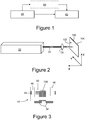
- the configuration of the laser setup may be designed in such a way that it will allow for making an array, which has both holes perpendicular to the glass surface and the angled ones, such as the holes 120 shown in the schematic cross section of a glass sheet 100 in Figure 12 .
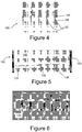
- Beam-shaping may also be used, if desired, as a means to change the hole shape, to various shapes such as shown schematically in holes 120 on glass sheet 100 of Figure 13 .
- Elliptical holes have been produce by irradiating with an elliptical beam, and other shapes are possible by beam shaping through apertures and imaging, overlapping beams, and/or other techniques and combinations of techniques.
- blind holes will develop if, for example, the laser burst duration is reduced from 90 ms to approximately 10-20 ms.
- the resulting damage is similar with respect to the 7-10 um micro-channel described above, starting at the front surface of the glass and extending to some length inside the glass, which is a function of the ratio between the shortened duration and the full duration. Etching of such a track will produce a blind hole.
- an acid-resistant film/coating to the glass surfaces can improve the hole shape even further.
- This coating may perform several functions: (a) protect the surface from the laser-ablated debris; (b) mitigate mechanical damage to the surface of the glass surrounding the exposed area; (c) prevent glass thinning during etching thus improving the hole aspect ratio.
- Such coating/film may be removable or it may be left on the glass if it does not prevent further processing.
Landscapes
- Engineering & Computer Science (AREA)
- Physics & Mathematics (AREA)
- Optics & Photonics (AREA)
- Chemical & Material Sciences (AREA)
- Mechanical Engineering (AREA)
- Plasma & Fusion (AREA)
- Materials Engineering (AREA)
- Organic Chemistry (AREA)
- General Chemical & Material Sciences (AREA)
- Geochemistry & Mineralogy (AREA)
- Life Sciences & Earth Sciences (AREA)
- Chemical Kinetics & Catalysis (AREA)
- Health & Medical Sciences (AREA)
- Toxicology (AREA)
- Re-Forming, After-Treatment, Cutting And Transporting Of Glass Products (AREA)
- Surface Treatment Of Glass (AREA)
- Laser Beam Processing (AREA)
- Lasers (AREA)
Claims (13)
- Verfahren zum Herstellen einer hochdichten Lochanordnung in Glas, wobei das Verfahren umfasst:Bereitstellen eines Glasstücks mit einer vorderen Oberfläche;Bestrahlen der vorderen Oberfläche des Glasstücks mit einem UV-Laserstrahl, wobei der Strahl mit einer Linse innerhalb von +/- 100 µm bezüglich der vorderen Oberfläche des Glasstücks fokussiert wird, wobei die Linse eine numerische Öffnung im Bereich von 0,1 bis 0,4 aufweist, um offene Löcher zu erzeugen, die sich von der vorderen Oberfläche des Glasstücks in das Glasstück erstrecken, wobei die Löcher einen Durchmesser im Bereich von 5 bis 15 µm und ein Seitenverhältnis von mindestens 20:1 aufweisen.
- Verfahren nach Anspruch 1, wobei der im Bestrahlungsschritt verwendete Nah-UV-Laser ein Nd:KGW-(Neodym-dotierter Kalium-Gadolinium-Wolframat)-Laser ist, der mit einer Wellenlänge von 355 µm betrieben wird.
- Verfahren nach Anspruch 1 oder 2, wobei die numerische Öffnung der im Bestrahlungsschritt verwendeten Linse im Bereich von 0,12 bis 0,15 für eine Glasdicke zwischen 0,3 mm und 0,63 mm ist.
- Verfahren nach Anspruch 3, wobei die numerische Öffnung der Linse im Bereich von 0,12 bis 0,13 ist.
- Verfahren nach einem der Ansprüche 1 bis 4, wobei der Laser während des Bestrahlungsschritts bei einer Frequenz im Bereich von 5 bis 50 kHz betrieben wird.
- Verfahren nach Anspruch 5, wobei der Laser während des Bestrahlungsschritts bei einer Frequenz im Bereich von 10 bis 20 kHz betrieben wird.
- Verfahren nach Anspruch 6, wobei der Laser während des Bestrahlungsschritts bei einer Frequenz im Bereich von 12 bis 18 kHz betrieben wird.
- Verfahren nach einem der Ansprüche 1 bis 7, wobei der Bestrahlungsschritt das Bestrahlen der vorderen Oberfläche des Glasstücks mit einem UV-Laserstrahl für eine Dauer im Bereich von 8 bis 150 Millisekunden pro Loch umfasst.
- Verfahren nach einem der Ansprüche 1 bis 7, wobei das Glas eine Dicke von 0,63 mm aufweist und der Bestrahlungsschritt das Bestrahlen der vorderen Oberfläche des Glasstücks mit einem UV-Laserstrahl für eine Dauer im Bereich von 60 bis 120 Millisekunden pro Loch umfasst.
- Verfahren nach einem der Ansprüche 1 bis 7, wobei das Glas eine Dicke von 0,63 mm aufweist und der Bestrahlungsschritt das Bestrahlen der vorderen Oberfläche des Glasstücks mit einem UV-Laserstrahl für eine Dauer im Bereich von 80 bis 100 Millisekunden pro Loch umfasst.
- Verfahren nach einem der Ansprüche 1 bis 10, wobei das Verfahren ferner das Ätzen des Glasstücks in einer HF + HNO3-Lösung umfasst.
- Verfahren nach Anspruch 11, wobei der Schritt des Ätzens ferner das Ätzen in einer Lösung aus 20 % HF + 10 % HNO3-Lösung umfasst.
- Verfahren nach einem der Ansprüche 1 bis 12, ferner umfassend, nach dem Bestrahlen und vor dem Ätzen, das Polieren der vorderen Oberfläche des Glasstücks.
Applications Claiming Priority (2)
| Application Number | Priority Date | Filing Date | Title |
|---|---|---|---|
| US41815210P | 2010-11-30 | 2010-11-30 | |
| PCT/US2011/062520 WO2012075072A2 (en) | 2010-11-30 | 2011-11-30 | Methods of forming high-density arrays of holes in glass |
Publications (2)
| Publication Number | Publication Date |
|---|---|
| EP2646384A2 EP2646384A2 (de) | 2013-10-09 |
| EP2646384B1 true EP2646384B1 (de) | 2019-03-27 |
Family
ID=45390179
Family Applications (1)
| Application Number | Title | Priority Date | Filing Date |
|---|---|---|---|
| EP11799537.3A Not-in-force EP2646384B1 (de) | 2010-11-30 | 2011-11-30 | Verfahren zur herstellung von hochdichten lochanordnungen in glas |
Country Status (7)
| Country | Link |
|---|---|
| US (2) | US9278886B2 (de) |
| EP (1) | EP2646384B1 (de) |
| JP (1) | JP5905899B2 (de) |
| KR (1) | KR101917401B1 (de) |
| CN (2) | CN103237771B (de) |
| TW (1) | TWI599429B (de) |
| WO (1) | WO2012075072A2 (de) |
Families Citing this family (103)
| Publication number | Priority date | Publication date | Assignee | Title |
|---|---|---|---|---|
| TWI547454B (zh) * | 2011-05-31 | 2016-09-01 | 康寧公司 | 於玻璃中高速製造微孔洞的方法 |
| US9938186B2 (en) | 2012-04-13 | 2018-04-10 | Corning Incorporated | Strengthened glass articles having etched features and methods of forming the same |
| WO2014079478A1 (en) | 2012-11-20 | 2014-05-30 | Light In Light Srl | High speed laser processing of transparent materials |
| CN105246850B (zh) * | 2012-11-29 | 2018-01-30 | 康宁股份有限公司 | 通过激光损坏和蚀刻制造玻璃制品的方法 |
| EP2925482A1 (de) | 2012-11-29 | 2015-10-07 | Corning Incorporated | Opferdeckschichten für laserbohrsubstrate und entsprechende verfahren |
| EP2754524B1 (de) | 2013-01-15 | 2015-11-25 | Corning Laser Technologies GmbH | Verfahren und Vorrichtung zum laserbasierten Bearbeiten von flächigen Substraten, d.h. Wafer oder Glaselement, unter Verwendung einer Laserstrahlbrennlinie |
| EP2781296B1 (de) | 2013-03-21 | 2020-10-21 | Corning Laser Technologies GmbH | Vorrichtung und verfahren zum ausschneiden von konturen aus flächigen substraten mittels laser |
| DE112013007305A5 (de) | 2013-08-07 | 2016-06-02 | Trumpf Laser- Und Systemtechnik Gmbh | Verfahren zum Bearbeiten eines plattenartigen Werkstückes mit einer transparenten, gläsernen, glasartigen keramischen und/oder kristallinen Lage, Trennvorrichtung für ein derartiges Werkstück sowie Produkt aus einem derartigen Werkstück |
| US9296646B2 (en) | 2013-08-29 | 2016-03-29 | Corning Incorporated | Methods for forming vias in glass substrates |
| US10005152B2 (en) * | 2013-11-19 | 2018-06-26 | Rofin-Sinar Technologies Llc | Method and apparatus for spiral cutting a glass tube using filamentation by burst ultrafast laser pulses |
| US9850160B2 (en) | 2013-12-17 | 2017-12-26 | Corning Incorporated | Laser cutting of display glass compositions |
| US11556039B2 (en) | 2013-12-17 | 2023-01-17 | Corning Incorporated | Electrochromic coated glass articles and methods for laser processing the same |
| US10442719B2 (en) | 2013-12-17 | 2019-10-15 | Corning Incorporated | Edge chamfering methods |
| US9815730B2 (en) | 2013-12-17 | 2017-11-14 | Corning Incorporated | Processing 3D shaped transparent brittle substrate |
| US9676167B2 (en) | 2013-12-17 | 2017-06-13 | Corning Incorporated | Laser processing of sapphire substrate and related applications |
| US9517963B2 (en) | 2013-12-17 | 2016-12-13 | Corning Incorporated | Method for rapid laser drilling of holes in glass and products made therefrom |
| US9701563B2 (en) | 2013-12-17 | 2017-07-11 | Corning Incorporated | Laser cut composite glass article and method of cutting |
| US20150165560A1 (en) | 2013-12-17 | 2015-06-18 | Corning Incorporated | Laser processing of slots and holes |
| CN105940323B (zh) * | 2014-01-29 | 2019-07-12 | 康宁公司 | 用于显示器照明的激光特征玻璃 |
| JP6262039B2 (ja) | 2014-03-17 | 2018-01-17 | 株式会社ディスコ | 板状物の加工方法 |
| TWI556898B (zh) * | 2014-04-29 | 2016-11-11 | Nat Inst Chung Shan Science & Technology | A method and system for preparing vertical micro-guide hole on fly black laser on opaque ceramic sheet |
| JP2017520906A (ja) * | 2014-04-30 | 2017-07-27 | コーニング インコーポレイテッド | 貫通ガラスバイアの作製のための接合材料のエッチバックプロセス |
| JP6301203B2 (ja) * | 2014-06-02 | 2018-03-28 | 株式会社ディスコ | チップの製造方法 |
| CN106687419A (zh) | 2014-07-08 | 2017-05-17 | 康宁股份有限公司 | 用于激光处理材料的方法和设备 |
| US11648623B2 (en) | 2014-07-14 | 2023-05-16 | Corning Incorporated | Systems and methods for processing transparent materials using adjustable laser beam focal lines |
| EP3169479B1 (de) | 2014-07-14 | 2019-10-02 | Corning Incorporated | Verfahren und system zum stoppen von inzidenter rissausbreitung in einem transparenten material |
| US10611667B2 (en) | 2014-07-14 | 2020-04-07 | Corning Incorporated | Method and system for forming perforations |
| EP3169476A1 (de) | 2014-07-14 | 2017-05-24 | Corning Incorporated | Schnittstellenblock, system und verfahren zum schneiden eines transparenten substrats mit einem wellenlängenbereich mit solch einem schnittstellenblock |
| CN106573829B (zh) | 2014-07-30 | 2020-05-05 | 康宁股份有限公司 | 超声槽和均匀玻璃基板蚀刻方法 |
| JP2016070900A (ja) * | 2014-10-02 | 2016-05-09 | セイコーエプソン株式会社 | 磁気計測装置の製造方法、ガスセルの製造方法、磁気計測装置、およびガスセル |
| JP2016080613A (ja) * | 2014-10-21 | 2016-05-16 | セイコーエプソン株式会社 | 磁気計測装置、ガスセル、磁気計測装置の製造方法、およびガスセルの製造方法 |
| JP6723236B2 (ja) | 2014-11-05 | 2020-07-15 | コーニング インコーポレイテッド | バイアボトムアップ電解メッキ方法 |
| US10047001B2 (en) | 2014-12-04 | 2018-08-14 | Corning Incorporated | Glass cutting systems and methods using non-diffracting laser beams |
| JP6104354B2 (ja) * | 2014-12-16 | 2017-03-29 | 旭硝子株式会社 | 貫通孔形成方法、貫通孔形成装置、および貫通孔を有するガラス基板の製造方法 |
| WO2016115017A1 (en) | 2015-01-12 | 2016-07-21 | Corning Incorporated | Laser cutting of thermally tempered substrates using the multi photon absorption method |
| HUE055461T2 (hu) | 2015-03-24 | 2021-11-29 | Corning Inc | Kijelzõ üveg kompozíciók lézeres vágása és feldolgozása |
| WO2016160391A1 (en) * | 2015-03-27 | 2016-10-06 | Corning Incorporated | Gas permeable window and method of fabricating the same |
| JP2018520003A (ja) | 2015-04-28 | 2018-07-26 | コーニング インコーポレイテッド | 出射犠牲カバー層を使用して基板に貫通孔をレーザー穿孔する方法、および対応するワークピース |
| CN107771169A (zh) * | 2015-05-18 | 2018-03-06 | 康宁股份有限公司 | 包含光提取特征的玻璃制品及其制造方法 |
| US20160347643A1 (en) * | 2015-05-29 | 2016-12-01 | Asahi Glass Company, Limited | Glass substrate manufacturing method |
| TW201704177A (zh) | 2015-06-10 | 2017-02-01 | 康寧公司 | 蝕刻玻璃基板的方法及玻璃基板 |
| EP3319911B1 (de) * | 2015-07-10 | 2023-04-19 | Corning Incorporated | Verfahren zur kontinuierlichen herstellung von löchern in flexiblen substratbahnen und zugehörige produkte |
| RU2598011C1 (ru) * | 2015-07-16 | 2016-09-20 | федеральное государственное автономное образовательное учреждение высшего образования "Санкт-Петербургский национальный исследовательский университет информационных технологий, механики и оптики" (Университет ИТМО) | Способ изготовления полой трехмерной структуры в объеме пластины фоточувствительного стекла |
| WO2017038075A1 (ja) * | 2015-08-31 | 2017-03-09 | 日本板硝子株式会社 | 微細構造付きガラスの製造方法 |
| US20170103249A1 (en) | 2015-10-09 | 2017-04-13 | Corning Incorporated | Glass-based substrate with vias and process of forming the same |
| JP2017088467A (ja) * | 2015-11-16 | 2017-05-25 | 旭硝子株式会社 | ガラス基板に孔を形成する装置および方法 |
| JP6885161B2 (ja) * | 2016-04-06 | 2021-06-09 | Agc株式会社 | 貫通孔を有するガラス基板の製造方法およびガラス基板に貫通孔を形成する方法 |
| US10292275B2 (en) * | 2016-04-06 | 2019-05-14 | AGC Inc. | Method of manufacturing glass substrate that has through hole, method of forming through hole in glass substrate and system for manufacturing glass substrate that has through hole |
| JP6938543B2 (ja) | 2016-05-06 | 2021-09-22 | コーニング インコーポレイテッド | 透明基板からの、輪郭設定された形状のレーザ切断及び取り外し |
| US10410883B2 (en) | 2016-06-01 | 2019-09-10 | Corning Incorporated | Articles and methods of forming vias in substrates |
| JP6911288B2 (ja) * | 2016-06-23 | 2021-07-28 | 凸版印刷株式会社 | ガラスの加工方法 |
| US10134657B2 (en) | 2016-06-29 | 2018-11-20 | Corning Incorporated | Inorganic wafer having through-holes attached to semiconductor wafer |
| US10794679B2 (en) | 2016-06-29 | 2020-10-06 | Corning Incorporated | Method and system for measuring geometric parameters of through holes |
| WO2018022476A1 (en) | 2016-07-29 | 2018-02-01 | Corning Incorporated | Apparatuses and methods for laser processing |
| JP2018024571A (ja) * | 2016-08-05 | 2018-02-15 | 旭硝子株式会社 | 孔を有するガラス基板の製造方法 |
| KR102423775B1 (ko) | 2016-08-30 | 2022-07-22 | 코닝 인코포레이티드 | 투명 재료의 레이저 가공 |
| TW201815710A (zh) | 2016-08-31 | 2018-05-01 | 美商康寧公司 | 具有經填充之孔洞的經強化玻璃系物件及製造其之方法 |
| JP6341245B2 (ja) | 2016-09-05 | 2018-06-13 | 大日本印刷株式会社 | 貫通電極基板の製造方法、貫通電極基板および半導体装置 |
| US10366904B2 (en) | 2016-09-08 | 2019-07-30 | Corning Incorporated | Articles having holes with morphology attributes and methods for fabricating the same |
| TW201822282A (zh) | 2016-09-09 | 2018-06-16 | 美商康寧公司 | 具有通孔的低表面粗糙度基板及其製作方法 |
| CN109803786B (zh) | 2016-09-30 | 2021-05-07 | 康宁股份有限公司 | 使用非轴对称束斑对透明工件进行激光加工的设备和方法 |
| JP6981422B2 (ja) * | 2016-10-20 | 2021-12-15 | Agc株式会社 | 孔を有するガラス基板の製造方法、インターポーザの製造方法、およびガラス基板に孔を形成する方法 |
| US11542190B2 (en) | 2016-10-24 | 2023-01-03 | Corning Incorporated | Substrate processing station for laser-based machining of sheet-like glass substrates |
| US10752534B2 (en) | 2016-11-01 | 2020-08-25 | Corning Incorporated | Apparatuses and methods for laser processing laminate workpiece stacks |
| JP2019535619A (ja) | 2016-11-04 | 2019-12-12 | コーニング インコーポレイテッド | 微細穿孔板システム、用途、および微細穿孔板システムを作る方法 |
| US10688599B2 (en) | 2017-02-09 | 2020-06-23 | Corning Incorporated | Apparatus and methods for laser processing transparent workpieces using phase shifted focal lines |
| KR20190116378A (ko) * | 2017-03-06 | 2019-10-14 | 엘피케이에프 레이저 앤드 일렉트로닉스 악티엔게젤샤프트 | 전자기 방사선과 후속 에칭공정을 이용해 재료 안으로 적어도 하나의 리세스를 도입하기 위한 방법 |
| CN106848832A (zh) * | 2017-04-24 | 2017-06-13 | 西南石油大学 | 一种小型化单巴条端面泵浦脉冲激光器 |
| WO2018200920A1 (en) | 2017-04-28 | 2018-11-01 | Corning Incorporated | Glass electrochemical sensor with wafer level stacking and through glass via (tgv) interconnects |
| US10580725B2 (en) | 2017-05-25 | 2020-03-03 | Corning Incorporated | Articles having vias with geometry attributes and methods for fabricating the same |
| US11078112B2 (en) | 2017-05-25 | 2021-08-03 | Corning Incorporated | Silica-containing substrates with vias having an axially variable sidewall taper and methods for forming the same |
| US10626040B2 (en) | 2017-06-15 | 2020-04-21 | Corning Incorporated | Articles capable of individual singulation |
| US20190024237A1 (en) | 2017-07-20 | 2019-01-24 | Corning Incorporated | Methods for metalizing vias within a substrate |
| TW201919805A (zh) * | 2017-08-25 | 2019-06-01 | 美商康寧公司 | 使用遠焦光束調整組件以雷射處理透明工件的設備與方法 |
| KR102487611B1 (ko) | 2017-10-27 | 2023-01-11 | 코닝 인코포레이티드 | 보호 물질을 사용한 관통 유리 비아 제조방법 |
| US12180108B2 (en) | 2017-12-19 | 2024-12-31 | Corning Incorporated | Methods for etching vias in glass-based articles employing positive charge organic molecules |
| WO2019135985A1 (en) | 2018-01-03 | 2019-07-11 | Corning Incorporated | Methods for making electrodes and providing electrical connections in sensors |
| US10917966B2 (en) | 2018-01-29 | 2021-02-09 | Corning Incorporated | Articles including metallized vias |
| TWI675126B (zh) * | 2018-02-14 | 2019-10-21 | 國立臺灣大學 | 針對矽晶圓之經製絨的表面上孔洞之擴孔方法 |
| US11554984B2 (en) | 2018-02-22 | 2023-01-17 | Corning Incorporated | Alkali-free borosilicate glasses with low post-HF etch roughness |
| WO2019193862A1 (ja) | 2018-04-05 | 2019-10-10 | パナソニックIpマネジメント株式会社 | 傷形成方法、試料分割方法、半導体素子の製造方法、半導体レーザ素子の製造方法及び半導体レーザ素子 |
| US11152294B2 (en) | 2018-04-09 | 2021-10-19 | Corning Incorporated | Hermetic metallized via with improved reliability |
| WO2020061437A1 (en) | 2018-09-20 | 2020-03-26 | Industrial Technology Research Institute | Copper metallization for through-glass vias on thin glass |
| WO2020112710A1 (en) | 2018-11-27 | 2020-06-04 | Corning Incorporated | 3d interposer with through glass vias - method of increasing adhesion between copper and glass surfaces and articles therefrom |
| JP2022519724A (ja) * | 2019-02-08 | 2022-03-24 | コーニング インコーポレイテッド | パルスレーザビーム焦点レンズおよび蒸気エッチングを使用して透明なワークピースをレーザ加工するための方法 |
| CN113474311B (zh) | 2019-02-21 | 2023-12-29 | 康宁股份有限公司 | 具有铜金属化贯穿孔的玻璃或玻璃陶瓷制品及其制造过程 |
| CN113613825B (zh) | 2019-03-21 | 2024-11-19 | 康宁股份有限公司 | 使用环形涡旋激光束在基于玻璃的物体中形成微孔的系统及方法 |
| TW202103830A (zh) * | 2019-03-25 | 2021-02-01 | 美商康寧公司 | 在玻璃中形成穿孔之方法 |
| US11952310B2 (en) | 2019-05-10 | 2024-04-09 | Corning Incorporated | Silicate glass compositions useful for the efficient production of through glass vias |
| US11881613B2 (en) | 2019-05-10 | 2024-01-23 | Corning Incorporated | Transparent package for window mounted transceiver unit |
| EP3990209B1 (de) | 2019-07-01 | 2023-10-04 | Corning Incorporated | Verfahren zur laserbearbeitung von transparenten werkstücken mittels gekrümmter quasi-nicht-beugender laserstrahlen |
| JP7205413B2 (ja) * | 2019-08-07 | 2023-01-17 | 株式会社Sumco | レーザマーク付きシリコンウェーハの製造方法 |
| US12383983B2 (en) | 2019-10-03 | 2025-08-12 | Orvinum Ag | Apparatus for creating a hole in a glass container |
| WO2021108079A1 (en) | 2019-11-27 | 2021-06-03 | Corning Incorporated | Fabricating laminate glass with blind vias |
| CN112894146A (zh) * | 2019-12-04 | 2021-06-04 | 大族激光科技产业集团股份有限公司 | 玻璃基板通孔的激光加工方法和装置 |
| WO2022055671A1 (en) * | 2020-09-09 | 2022-03-17 | Corning Incorporated | Glass substrates with blind vias having depth uniformity and methods for forming the same |
| JPWO2022075068A1 (de) * | 2020-10-06 | 2022-04-14 | ||
| EP4244889A1 (de) | 2020-11-16 | 2023-09-20 | Corning Incorporated | 3d-zwischenstück mit glasdurchgängen - verfahren zur erhöhung der haftung zwischen kupfer- und glasoberflächen und artikel daraus |
| CN113292236A (zh) * | 2021-05-21 | 2021-08-24 | 江西沃格光电股份有限公司 | 一种Mini-LED基板通孔的形成方法及电子设备 |
| KR102605271B1 (ko) | 2021-07-13 | 2023-11-27 | 주식회사 중우나라 | 유리기판의 관통홀 형성방법 |
| WO2024118449A1 (en) * | 2022-11-30 | 2024-06-06 | Corning Incorporated | Systems and methods for laser micromachining substrates using a liquid-assist medium and articles fabricated by the same |
| CN117263520A (zh) * | 2023-08-29 | 2023-12-22 | 北方夜视技术股份有限公司 | 一种铅玻璃通孔微通道板、其制作方法与用途 |
| WO2025164391A1 (ja) * | 2024-01-30 | 2025-08-07 | Agc株式会社 | ガラス基板の製造方法 |
Family Cites Families (28)
| Publication number | Priority date | Publication date | Assignee | Title |
|---|---|---|---|---|
| US5919607A (en) | 1995-10-26 | 1999-07-06 | Brown University Research Foundation | Photo-encoded selective etching for glass based microtechnology applications |
| JP2873937B2 (ja) | 1996-05-24 | 1999-03-24 | 工業技術院長 | ガラスの光微細加工方法 |
| JP3118203B2 (ja) * | 1997-03-27 | 2000-12-18 | 住友重機械工業株式会社 | レーザ加工方法 |
| JP4512786B2 (ja) * | 2000-11-17 | 2010-07-28 | 独立行政法人産業技術総合研究所 | ガラス基板の加工方法 |
| JP2002265233A (ja) | 2001-03-05 | 2002-09-18 | Nippon Sheet Glass Co Ltd | レーザ加工用母材ガラスおよびレーザ加工用ガラス |
| US6754429B2 (en) * | 2001-07-06 | 2004-06-22 | Corning Incorporated | Method of making optical fiber devices and devices thereof |
| JP2003226551A (ja) | 2002-02-05 | 2003-08-12 | Nippon Sheet Glass Co Ltd | 微細孔を有するガラス板およびその製造方法 |
| CA2428187C (en) * | 2002-05-08 | 2012-10-02 | National Research Council Of Canada | Method of fabricating sub-micron structures in transparent dielectric materials |
| US7106342B2 (en) | 2002-09-27 | 2006-09-12 | Lg Electronics Inc. | Method of controlling brightness of user-selected area for image display device |
| US7880117B2 (en) * | 2002-12-24 | 2011-02-01 | Panasonic Corporation | Method and apparatus of drilling high density submicron cavities using parallel laser beams |
| US6990285B2 (en) * | 2003-07-31 | 2006-01-24 | Corning Incorporated | Method of making at least one hole in a transparent body and devices made by this method |
| JP4849890B2 (ja) * | 2003-10-06 | 2012-01-11 | Hoya株式会社 | 貫通孔を有するガラス部品およびその製造方法 |
| JP2005144622A (ja) | 2003-11-18 | 2005-06-09 | Seiko Epson Corp | 構造体の製造方法、液滴吐出ヘッド、液滴吐出装置 |
| US7057135B2 (en) * | 2004-03-04 | 2006-06-06 | Matsushita Electric Industrial, Co. Ltd. | Method of precise laser nanomachining with UV ultrafast laser pulses |
| JP4631044B2 (ja) * | 2004-05-26 | 2011-02-16 | 国立大学法人北海道大学 | レーザ加工方法および装置 |
| KR20060000515A (ko) | 2004-06-29 | 2006-01-06 | 대주전자재료 주식회사 | 플라즈마 디스플레이 패널 격벽용 무연 유리 조성물 |
| US20060207976A1 (en) * | 2005-01-21 | 2006-09-21 | Bovatsek James M | Laser material micromachining with green femtosecond pulses |
| JP2006290630A (ja) * | 2005-02-23 | 2006-10-26 | Nippon Sheet Glass Co Ltd | レーザを用いたガラスの加工方法 |
| US20090013724A1 (en) * | 2006-02-22 | 2009-01-15 | Nippon Sheet Glass Company, Limited | Glass Processing Method Using Laser and Processing Device |
| JP4672689B2 (ja) * | 2006-02-22 | 2011-04-20 | 日本板硝子株式会社 | レーザを用いたガラスの加工方法および加工装置 |
| KR100868228B1 (ko) | 2007-12-04 | 2008-11-11 | 주식회사 켐트로닉스 | 유리 기판용 식각액 조성물 |
| US8257603B2 (en) * | 2008-08-29 | 2012-09-04 | Corning Incorporated | Laser patterning of glass bodies |
| US20100119808A1 (en) * | 2008-11-10 | 2010-05-13 | Xinghua Li | Method of making subsurface marks in glass |
| CN102300820B (zh) * | 2009-02-02 | 2014-02-26 | 旭硝子株式会社 | 半导体器件构件用玻璃基板及半导体器件构件用玻璃基板的制造方法 |
| DE102010025967B4 (de) * | 2010-07-02 | 2015-12-10 | Schott Ag | Verfahren zur Erzeugung einer Vielzahl von Löchern, Vorrichtung hierzu und Glas-Interposer |
| US20120052302A1 (en) | 2010-08-24 | 2012-03-01 | Matusick Joseph M | Method of strengthening edge of glass article |
| TWI547454B (zh) * | 2011-05-31 | 2016-09-01 | 康寧公司 | 於玻璃中高速製造微孔洞的方法 |
| EP2754524B1 (de) * | 2013-01-15 | 2015-11-25 | Corning Laser Technologies GmbH | Verfahren und Vorrichtung zum laserbasierten Bearbeiten von flächigen Substraten, d.h. Wafer oder Glaselement, unter Verwendung einer Laserstrahlbrennlinie |
-
2011
- 2011-11-30 US US13/989,914 patent/US9278886B2/en not_active Expired - Fee Related
- 2011-11-30 CN CN201180057698.5A patent/CN103237771B/zh not_active Expired - Fee Related
- 2011-11-30 CN CN201610872785.0A patent/CN106425129B/zh not_active Expired - Fee Related
- 2011-11-30 TW TW100144070A patent/TWI599429B/zh not_active IP Right Cessation
- 2011-11-30 EP EP11799537.3A patent/EP2646384B1/de not_active Not-in-force
- 2011-11-30 KR KR1020137015860A patent/KR101917401B1/ko not_active Expired - Fee Related
- 2011-11-30 JP JP2013542117A patent/JP5905899B2/ja active Active
- 2011-11-30 WO PCT/US2011/062520 patent/WO2012075072A2/en not_active Ceased
-
2015
- 2015-12-17 US US14/972,352 patent/US9802855B2/en not_active Expired - Fee Related
Non-Patent Citations (1)
| Title |
|---|
| None * |
Also Published As
| Publication number | Publication date |
|---|---|
| CN106425129A (zh) | 2017-02-22 |
| CN106425129B (zh) | 2018-07-17 |
| WO2012075072A3 (en) | 2012-10-18 |
| JP2014501686A (ja) | 2014-01-23 |
| KR101917401B1 (ko) | 2018-11-09 |
| US20130247615A1 (en) | 2013-09-26 |
| TWI599429B (zh) | 2017-09-21 |
| US20160102009A1 (en) | 2016-04-14 |
| EP2646384A2 (de) | 2013-10-09 |
| JP5905899B2 (ja) | 2016-04-20 |
| WO2012075072A2 (en) | 2012-06-07 |
| CN103237771B (zh) | 2016-10-19 |
| KR20130135873A (ko) | 2013-12-11 |
| US9802855B2 (en) | 2017-10-31 |
| CN103237771A (zh) | 2013-08-07 |
| TW201235145A (en) | 2012-09-01 |
| US9278886B2 (en) | 2016-03-08 |
Similar Documents
| Publication | Publication Date | Title |
|---|---|---|
| EP2646384B1 (de) | Verfahren zur herstellung von hochdichten lochanordnungen in glas | |
| US9321680B2 (en) | High-speed micro-hole fabrication in glass | |
| EP1990125B1 (de) | Glasbearbeitungsverfahren mit laser | |
| US8257603B2 (en) | Laser patterning of glass bodies | |
| JP4630971B2 (ja) | パルスレーザによる微小構造の形成方法 | |
| US8591753B2 (en) | Laser processing method | |
| US8894868B2 (en) | Substrate containing aperture and methods of forming the same | |
| CN113614045A (zh) | 采用脉冲激光束聚焦线和气相蚀刻对透明工件进行激光加工的方法 | |
| JP2011037707A (ja) | レーザを用いたガラスの加工方法および加工装置 | |
| JP2017511777A (ja) | エッジ面取り加工方法 | |
| JP2003226551A (ja) | 微細孔を有するガラス板およびその製造方法 | |
| WO2012014709A1 (ja) | レーザ加工方法 | |
| US20260078045A1 (en) | Method for preparing and/or performing the separation of a substrate element and substrate sub-element | |
| JP2020142941A (ja) | ガラス用エッチング液およびガラス基板製造方法 | |
| JP6162975B2 (ja) | 微細孔を備えた基板の製造方法 | |
| KR102491775B1 (ko) | 레이저와 습식 식각을 이용한 박막 글라스 커팅 및 커팅면 형상 가공 방법 | |
| JP7251704B2 (ja) | ガラス用エッチング液およびガラス基板製造方法 | |
| CN116621463B (zh) | 一种孔结构形成方法 | |
| TW202344333A (zh) | 利用紅外線鐳射的快速精密貫通孔形成方法 | |
| CN121159147A (zh) | 一种玻璃盲槽侧壁粗糙度的优化加工方法 | |
| CN112719602A (zh) | 一种激光化学腐蚀加工灰度阶梯结构产品的方法及其系统 |
Legal Events
| Date | Code | Title | Description |
|---|---|---|---|
| PUAI | Public reference made under article 153(3) epc to a published international application that has entered the european phase |
Free format text: ORIGINAL CODE: 0009012 |
|
| 17P | Request for examination filed |
Effective date: 20130606 |
|
| AK | Designated contracting states |
Kind code of ref document: A2 Designated state(s): AL AT BE BG CH CY CZ DE DK EE ES FI FR GB GR HR HU IE IS IT LI LT LU LV MC MK MT NL NO PL PT RO RS SE SI SK SM TR |
|
| DAX | Request for extension of the european patent (deleted) | ||
| STAA | Information on the status of an ep patent application or granted ep patent |
Free format text: STATUS: EXAMINATION IS IN PROGRESS |
|
| 17Q | First examination report despatched |
Effective date: 20171201 |
|
| GRAP | Despatch of communication of intention to grant a patent |
Free format text: ORIGINAL CODE: EPIDOSNIGR1 |
|
| STAA | Information on the status of an ep patent application or granted ep patent |
Free format text: STATUS: GRANT OF PATENT IS INTENDED |
|
| GRAS | Grant fee paid |
Free format text: ORIGINAL CODE: EPIDOSNIGR3 |
|
| INTG | Intention to grant announced |
Effective date: 20190123 |
|
| GRAA | (expected) grant |
Free format text: ORIGINAL CODE: 0009210 |
|
| STAA | Information on the status of an ep patent application or granted ep patent |
Free format text: STATUS: THE PATENT HAS BEEN GRANTED |
|
| AK | Designated contracting states |
Kind code of ref document: B1 Designated state(s): AL AT BE BG CH CY CZ DE DK EE ES FI FR GB GR HR HU IE IS IT LI LT LU LV MC MK MT NL NO PL PT RO RS SE SI SK SM TR |
|
| REG | Reference to a national code |
Ref country code: GB Ref legal event code: FG4D |
|
| REG | Reference to a national code |
Ref country code: CH Ref legal event code: EP |
|
| REG | Reference to a national code |
Ref country code: DE Ref legal event code: R082 Ref document number: 602011057579 Country of ref document: DE Representative=s name: HERNANDEZ, YORCK, DIPL.-ING., DE |
|
| REG | Reference to a national code |
Ref country code: AT Ref legal event code: REF Ref document number: 1112850 Country of ref document: AT Kind code of ref document: T Effective date: 20190415 |
|
| REG | Reference to a national code |
Ref country code: IE Ref legal event code: FG4D |
|
| REG | Reference to a national code |
Ref country code: DE Ref legal event code: R096 Ref document number: 602011057579 Country of ref document: DE |
|
| PG25 | Lapsed in a contracting state [announced via postgrant information from national office to epo] |
Ref country code: SE Free format text: LAPSE BECAUSE OF FAILURE TO SUBMIT A TRANSLATION OF THE DESCRIPTION OR TO PAY THE FEE WITHIN THE PRESCRIBED TIME-LIMIT Effective date: 20190327 Ref country code: LT Free format text: LAPSE BECAUSE OF FAILURE TO SUBMIT A TRANSLATION OF THE DESCRIPTION OR TO PAY THE FEE WITHIN THE PRESCRIBED TIME-LIMIT Effective date: 20190327 Ref country code: NO Free format text: LAPSE BECAUSE OF FAILURE TO SUBMIT A TRANSLATION OF THE DESCRIPTION OR TO PAY THE FEE WITHIN THE PRESCRIBED TIME-LIMIT Effective date: 20190627 Ref country code: FI Free format text: LAPSE BECAUSE OF FAILURE TO SUBMIT A TRANSLATION OF THE DESCRIPTION OR TO PAY THE FEE WITHIN THE PRESCRIBED TIME-LIMIT Effective date: 20190327 |
|
| REG | Reference to a national code |
Ref country code: NL Ref legal event code: MP Effective date: 20190327 |
|
| PG25 | Lapsed in a contracting state [announced via postgrant information from national office to epo] |
Ref country code: BG Free format text: LAPSE BECAUSE OF FAILURE TO SUBMIT A TRANSLATION OF THE DESCRIPTION OR TO PAY THE FEE WITHIN THE PRESCRIBED TIME-LIMIT Effective date: 20190627 Ref country code: LV Free format text: LAPSE BECAUSE OF FAILURE TO SUBMIT A TRANSLATION OF THE DESCRIPTION OR TO PAY THE FEE WITHIN THE PRESCRIBED TIME-LIMIT Effective date: 20190327 Ref country code: NL Free format text: LAPSE BECAUSE OF FAILURE TO SUBMIT A TRANSLATION OF THE DESCRIPTION OR TO PAY THE FEE WITHIN THE PRESCRIBED TIME-LIMIT Effective date: 20190327 Ref country code: RS Free format text: LAPSE BECAUSE OF FAILURE TO SUBMIT A TRANSLATION OF THE DESCRIPTION OR TO PAY THE FEE WITHIN THE PRESCRIBED TIME-LIMIT Effective date: 20190327 Ref country code: GR Free format text: LAPSE BECAUSE OF FAILURE TO SUBMIT A TRANSLATION OF THE DESCRIPTION OR TO PAY THE FEE WITHIN THE PRESCRIBED TIME-LIMIT Effective date: 20190628 Ref country code: HR Free format text: LAPSE BECAUSE OF FAILURE TO SUBMIT A TRANSLATION OF THE DESCRIPTION OR TO PAY THE FEE WITHIN THE PRESCRIBED TIME-LIMIT Effective date: 20190327 |
|
| REG | Reference to a national code |
Ref country code: AT Ref legal event code: MK05 Ref document number: 1112850 Country of ref document: AT Kind code of ref document: T Effective date: 20190327 |
|
| PG25 | Lapsed in a contracting state [announced via postgrant information from national office to epo] |
Ref country code: CZ Free format text: LAPSE BECAUSE OF FAILURE TO SUBMIT A TRANSLATION OF THE DESCRIPTION OR TO PAY THE FEE WITHIN THE PRESCRIBED TIME-LIMIT Effective date: 20190327 Ref country code: RO Free format text: LAPSE BECAUSE OF FAILURE TO SUBMIT A TRANSLATION OF THE DESCRIPTION OR TO PAY THE FEE WITHIN THE PRESCRIBED TIME-LIMIT Effective date: 20190327 Ref country code: IT Free format text: LAPSE BECAUSE OF FAILURE TO SUBMIT A TRANSLATION OF THE DESCRIPTION OR TO PAY THE FEE WITHIN THE PRESCRIBED TIME-LIMIT Effective date: 20190327 Ref country code: AL Free format text: LAPSE BECAUSE OF FAILURE TO SUBMIT A TRANSLATION OF THE DESCRIPTION OR TO PAY THE FEE WITHIN THE PRESCRIBED TIME-LIMIT Effective date: 20190327 Ref country code: PT Free format text: LAPSE BECAUSE OF FAILURE TO SUBMIT A TRANSLATION OF THE DESCRIPTION OR TO PAY THE FEE WITHIN THE PRESCRIBED TIME-LIMIT Effective date: 20190727 Ref country code: SK Free format text: LAPSE BECAUSE OF FAILURE TO SUBMIT A TRANSLATION OF THE DESCRIPTION OR TO PAY THE FEE WITHIN THE PRESCRIBED TIME-LIMIT Effective date: 20190327 Ref country code: EE Free format text: LAPSE BECAUSE OF FAILURE TO SUBMIT A TRANSLATION OF THE DESCRIPTION OR TO PAY THE FEE WITHIN THE PRESCRIBED TIME-LIMIT Effective date: 20190327 Ref country code: ES Free format text: LAPSE BECAUSE OF FAILURE TO SUBMIT A TRANSLATION OF THE DESCRIPTION OR TO PAY THE FEE WITHIN THE PRESCRIBED TIME-LIMIT Effective date: 20190327 |
|
| PG25 | Lapsed in a contracting state [announced via postgrant information from national office to epo] |
Ref country code: SM Free format text: LAPSE BECAUSE OF FAILURE TO SUBMIT A TRANSLATION OF THE DESCRIPTION OR TO PAY THE FEE WITHIN THE PRESCRIBED TIME-LIMIT Effective date: 20190327 Ref country code: PL Free format text: LAPSE BECAUSE OF FAILURE TO SUBMIT A TRANSLATION OF THE DESCRIPTION OR TO PAY THE FEE WITHIN THE PRESCRIBED TIME-LIMIT Effective date: 20190327 |
|
| PG25 | Lapsed in a contracting state [announced via postgrant information from national office to epo] |
Ref country code: IS Free format text: LAPSE BECAUSE OF FAILURE TO SUBMIT A TRANSLATION OF THE DESCRIPTION OR TO PAY THE FEE WITHIN THE PRESCRIBED TIME-LIMIT Effective date: 20190727 Ref country code: AT Free format text: LAPSE BECAUSE OF FAILURE TO SUBMIT A TRANSLATION OF THE DESCRIPTION OR TO PAY THE FEE WITHIN THE PRESCRIBED TIME-LIMIT Effective date: 20190327 |
|
| REG | Reference to a national code |
Ref country code: DE Ref legal event code: R097 Ref document number: 602011057579 Country of ref document: DE |
|
| PG25 | Lapsed in a contracting state [announced via postgrant information from national office to epo] |
Ref country code: DK Free format text: LAPSE BECAUSE OF FAILURE TO SUBMIT A TRANSLATION OF THE DESCRIPTION OR TO PAY THE FEE WITHIN THE PRESCRIBED TIME-LIMIT Effective date: 20190327 |
|
| PGFP | Annual fee paid to national office [announced via postgrant information from national office to epo] |
Ref country code: DE Payment date: 20191017 Year of fee payment: 9 |
|
| PLBE | No opposition filed within time limit |
Free format text: ORIGINAL CODE: 0009261 |
|
| STAA | Information on the status of an ep patent application or granted ep patent |
Free format text: STATUS: NO OPPOSITION FILED WITHIN TIME LIMIT |
|
| PG25 | Lapsed in a contracting state [announced via postgrant information from national office to epo] |
Ref country code: SI Free format text: LAPSE BECAUSE OF FAILURE TO SUBMIT A TRANSLATION OF THE DESCRIPTION OR TO PAY THE FEE WITHIN THE PRESCRIBED TIME-LIMIT Effective date: 20190327 |
|
| PGFP | Annual fee paid to national office [announced via postgrant information from national office to epo] |
Ref country code: FR Payment date: 20191029 Year of fee payment: 9 |
|
| 26N | No opposition filed |
Effective date: 20200103 |
|
| PG25 | Lapsed in a contracting state [announced via postgrant information from national office to epo] |
Ref country code: TR Free format text: LAPSE BECAUSE OF FAILURE TO SUBMIT A TRANSLATION OF THE DESCRIPTION OR TO PAY THE FEE WITHIN THE PRESCRIBED TIME-LIMIT Effective date: 20190327 |
|
| REG | Reference to a national code |
Ref country code: CH Ref legal event code: PL |
|
| PG25 | Lapsed in a contracting state [announced via postgrant information from national office to epo] |
Ref country code: LI Free format text: LAPSE BECAUSE OF NON-PAYMENT OF DUE FEES Effective date: 20191130 Ref country code: CH Free format text: LAPSE BECAUSE OF NON-PAYMENT OF DUE FEES Effective date: 20191130 Ref country code: LU Free format text: LAPSE BECAUSE OF NON-PAYMENT OF DUE FEES Effective date: 20191130 Ref country code: MC Free format text: LAPSE BECAUSE OF FAILURE TO SUBMIT A TRANSLATION OF THE DESCRIPTION OR TO PAY THE FEE WITHIN THE PRESCRIBED TIME-LIMIT Effective date: 20190327 |
|
| REG | Reference to a national code |
Ref country code: BE Ref legal event code: MM Effective date: 20191130 |
|
| GBPC | Gb: european patent ceased through non-payment of renewal fee |
Effective date: 20191130 |
|
| PG25 | Lapsed in a contracting state [announced via postgrant information from national office to epo] |
Ref country code: IE Free format text: LAPSE BECAUSE OF NON-PAYMENT OF DUE FEES Effective date: 20191130 Ref country code: GB Free format text: LAPSE BECAUSE OF NON-PAYMENT OF DUE FEES Effective date: 20191130 |
|
| PG25 | Lapsed in a contracting state [announced via postgrant information from national office to epo] |
Ref country code: BE Free format text: LAPSE BECAUSE OF NON-PAYMENT OF DUE FEES Effective date: 20191130 |
|
| PG25 | Lapsed in a contracting state [announced via postgrant information from national office to epo] |
Ref country code: CY Free format text: LAPSE BECAUSE OF FAILURE TO SUBMIT A TRANSLATION OF THE DESCRIPTION OR TO PAY THE FEE WITHIN THE PRESCRIBED TIME-LIMIT Effective date: 20190327 |
|
| REG | Reference to a national code |
Ref country code: DE Ref legal event code: R119 Ref document number: 602011057579 Country of ref document: DE |
|
| PG25 | Lapsed in a contracting state [announced via postgrant information from national office to epo] |
Ref country code: MT Free format text: LAPSE BECAUSE OF FAILURE TO SUBMIT A TRANSLATION OF THE DESCRIPTION OR TO PAY THE FEE WITHIN THE PRESCRIBED TIME-LIMIT Effective date: 20190327 Ref country code: HU Free format text: LAPSE BECAUSE OF FAILURE TO SUBMIT A TRANSLATION OF THE DESCRIPTION OR TO PAY THE FEE WITHIN THE PRESCRIBED TIME-LIMIT; INVALID AB INITIO Effective date: 20111130 |
|
| PG25 | Lapsed in a contracting state [announced via postgrant information from national office to epo] |
Ref country code: FR Free format text: LAPSE BECAUSE OF NON-PAYMENT OF DUE FEES Effective date: 20201130 |
|
| PG25 | Lapsed in a contracting state [announced via postgrant information from national office to epo] |
Ref country code: DE Free format text: LAPSE BECAUSE OF NON-PAYMENT OF DUE FEES Effective date: 20210601 |
|
| PG25 | Lapsed in a contracting state [announced via postgrant information from national office to epo] |
Ref country code: MK Free format text: LAPSE BECAUSE OF FAILURE TO SUBMIT A TRANSLATION OF THE DESCRIPTION OR TO PAY THE FEE WITHIN THE PRESCRIBED TIME-LIMIT Effective date: 20190327 |