EP2641809B1 - Systèmes et procédés de stabilisation de chariots élévateurs lors du braquage - Google Patents
Systèmes et procédés de stabilisation de chariots élévateurs lors du braquage Download PDFInfo
- Publication number
- EP2641809B1 EP2641809B1 EP13151790.6A EP13151790A EP2641809B1 EP 2641809 B1 EP2641809 B1 EP 2641809B1 EP 13151790 A EP13151790 A EP 13151790A EP 2641809 B1 EP2641809 B1 EP 2641809B1
- Authority
- EP
- European Patent Office
- Prior art keywords
- caster
- slide mechanism
- drive unit
- set forth
- load bearing
- Prior art date
- Legal status (The legal status is an assumption and is not a legal conclusion. Google has not performed a legal analysis and makes no representation as to the accuracy of the status listed.)
- Active
Links
- 238000000034 method Methods 0.000 title claims description 14
- 230000007246 mechanism Effects 0.000 claims description 70
- 230000000087 stabilizing effect Effects 0.000 claims description 6
- 235000004443 Ricinus communis Nutrition 0.000 description 12
- 240000000528 Ricinus communis Species 0.000 description 6
- 230000008901 benefit Effects 0.000 description 4
- 239000006096 absorbing agent Substances 0.000 description 2
- 238000007792 addition Methods 0.000 description 2
- 238000013016 damping Methods 0.000 description 2
- 239000000463 material Substances 0.000 description 2
- 230000008569 process Effects 0.000 description 2
- 230000035939 shock Effects 0.000 description 2
- 230000006641 stabilisation Effects 0.000 description 2
- 238000011105 stabilization Methods 0.000 description 2
- 239000000725 suspension Substances 0.000 description 2
- 229910000831 Steel Inorganic materials 0.000 description 1
- 230000008859 change Effects 0.000 description 1
- 230000000694 effects Effects 0.000 description 1
- 230000002708 enhancing effect Effects 0.000 description 1
- 230000003993 interaction Effects 0.000 description 1
- 238000012986 modification Methods 0.000 description 1
- 230000004048 modification Effects 0.000 description 1
- 230000010355 oscillation Effects 0.000 description 1
- 238000005096 rolling process Methods 0.000 description 1
- 239000010959 steel Substances 0.000 description 1
- 238000003466 welding Methods 0.000 description 1
Images


Classifications
-
- B—PERFORMING OPERATIONS; TRANSPORTING
- B62—LAND VEHICLES FOR TRAVELLING OTHERWISE THAN ON RAILS
- B62B—HAND-PROPELLED VEHICLES, e.g. HAND CARTS OR PERAMBULATORS; SLEDGES
- B62B3/00—Hand carts having more than one axis carrying transport wheels; Steering devices therefor; Equipment therefor
- B62B3/001—Steering devices
-
- B—PERFORMING OPERATIONS; TRANSPORTING
- B62—LAND VEHICLES FOR TRAVELLING OTHERWISE THAN ON RAILS
- B62B—HAND-PROPELLED VEHICLES, e.g. HAND CARTS OR PERAMBULATORS; SLEDGES
- B62B3/00—Hand carts having more than one axis carrying transport wheels; Steering devices therefor; Equipment therefor
- B62B3/04—Hand carts having more than one axis carrying transport wheels; Steering devices therefor; Equipment therefor involving means for grappling or securing in place objects to be carried; Loading or unloading equipment
- B62B3/06—Hand carts having more than one axis carrying transport wheels; Steering devices therefor; Equipment therefor involving means for grappling or securing in place objects to be carried; Loading or unloading equipment for simply clearing the load from the ground
-
- B—PERFORMING OPERATIONS; TRANSPORTING
- B66—HOISTING; LIFTING; HAULING
- B66F—HOISTING, LIFTING, HAULING OR PUSHING, NOT OTHERWISE PROVIDED FOR, e.g. DEVICES WHICH APPLY A LIFTING OR PUSHING FORCE DIRECTLY TO THE SURFACE OF A LOAD
- B66F9/00—Devices for lifting or lowering bulky or heavy goods for loading or unloading purposes
- B66F9/06—Devices for lifting or lowering bulky or heavy goods for loading or unloading purposes movable, with their loads, on wheels or the like, e.g. fork-lift trucks
- B66F9/075—Constructional features or details
- B66F9/07559—Stabilizing means
-
- B—PERFORMING OPERATIONS; TRANSPORTING
- B60—VEHICLES IN GENERAL
- B60G—VEHICLE SUSPENSION ARRANGEMENTS
- B60G2200/00—Indexing codes relating to suspension types
- B60G2200/40—Indexing codes relating to the wheels in the suspensions
- B60G2200/445—Self-steered wheels
-
- B—PERFORMING OPERATIONS; TRANSPORTING
- B60—VEHICLES IN GENERAL
- B60G—VEHICLE SUSPENSION ARRANGEMENTS
- B60G2300/00—Indexing codes relating to the type of vehicle
- B60G2300/02—Trucks; Load vehicles
- B60G2300/022—Fork lift trucks, Clark
-
- B—PERFORMING OPERATIONS; TRANSPORTING
- B60—VEHICLES IN GENERAL
- B60G—VEHICLE SUSPENSION ARRANGEMENTS
- B60G2500/00—Indexing codes relating to the regulated action or device
- B60G2500/30—Height or ground clearance
- B60G2500/32—Height or ground clearance of only one vehicle part or side
- B60G2500/326—Height or ground clearance of only one vehicle part or side only left or right side
-
- B—PERFORMING OPERATIONS; TRANSPORTING
- B62—LAND VEHICLES FOR TRAVELLING OTHERWISE THAN ON RAILS
- B62B—HAND-PROPELLED VEHICLES, e.g. HAND CARTS OR PERAMBULATORS; SLEDGES
- B62B2301/00—Wheel arrangements; Steering; Stability; Wheel suspension
- B62B2301/08—Wheel arrangements; Steering; Stability; Wheel suspension comprising additional wheels to increase stability
-
- B—PERFORMING OPERATIONS; TRANSPORTING
- B62—LAND VEHICLES FOR TRAVELLING OTHERWISE THAN ON RAILS
- B62B—HAND-PROPELLED VEHICLES, e.g. HAND CARTS OR PERAMBULATORS; SLEDGES
- B62B2301/00—Wheel arrangements; Steering; Stability; Wheel suspension
- B62B2301/20—Resilient wheel suspension using springs
- B62B2301/23—Resilient wheel suspension using springs the pressure of the wheel on the ground being controlled, e.g. by the load or the wheel slip
Definitions
- the present invention relates to the field of industrial lift trucks, and more specifically to systems and methods for improved turning stability control for lift trucks.
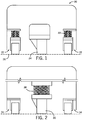
- a simplified front view of a lift truck 20 is shown using spring loaded casters 22 and a center drive tire 24 spaced between the two spring loaded casters 22.
- the spring loaded casters allow for lift truck turning and driving over rough floors 26 while still maintaining a smooth ride and good contact force for the drive tire 24.
- the casters 22 are adjusted to find an optimum operation between drive tire slippage and the truck rocking or tilting between both casters.
- FIG. 2 still other varieties of lift truck configurations use fixed casters 34 and a suspended drive tire 36.
- This configuration lets the suspension spring 38 provide enough force to keep the suspended drive tire 36 in contact with the floor, and is more prevalent with very flat floors.
- operators of a truck with this configuration are known to feel oscillations and the truck may tilt on most every bump. Also, the effect of hitting an object with one caster may cause a noticeable contact and tilt felt by the operator.
- the present invention overcomes the drawbacks of the previous lift truck systems and methods by providing stability control features to reduce or eliminate swaying of the truck away from a turn or bank into a turn.
- a system for stabilizing a lift truck comprising a rotatable drive unit, the drive unit including a steerable drive tire.
- a first slide mechanism is coupled to the rotatable drive unit.
- a caster is mounted to a caster plate, with a second slide mechanism mounted to the caster plate.
- a steering mechanism is coupled to the rotatable drive unit, such that when the steering mechanism is moved to steer the steerable drive tire, the first slide mechanism interacts with the second slide mechanism to affect a pressure on the caster.
- the system comprises a rotatable drive unit, the drive unit including a steerable drive tire.
- a left side slide mechanism and a right side slide mechanism are coupled to the rotatable drive unit.
- a left caster is mounted to a left caster plate, and a right caster is mounted to a right caster plate.
- a left caster slide mechanism is mounted to the left caster plate, and a right caster slide mechanism is mounted to the right caster plate.
- a steering mechanism is coupled to the rotatable drive unit, such that when the steering mechanism is moved to turn the lift truck to the left, the right side slide mechanism interacts with the right caster slide mechanism to produce a downward pressure on the right caster.
- a method for stabilizing a lift truck comprises the steps of providing a rotatable drive unit, the drive unit including a steerable drive tire; providing a first slide mechanism coupled to the rotatable drive unit; providing a caster mounted to a caster plate; providing a second slide mechanism mounted to the caster plate; providing a steering mechanism coupled to the rotatable drive unit, the steering mechanism for steering the steerable drive tire and causing the first slide mechanism to interact with the second slide mechanism; and affecting a pressure on the caster.
- Embodiments of the invention described herein, either alone or in combination, are well suited to provide a stabilized lift truck.
- the truck achieves improved turning stabilization through one or more individual or combined improvements that are configured to minimize side to side motion caused by vehicle turning.
- the collective improvements provide a simple mechanical solution, and allow greater productivity by permitting faster travel speeds.
- FIG. 3 depicts a hand/rider truck 50 having load bearing forks 52 and a steering control mechanism 54 that includes a movable steering arm 56 and steering arm handle 58.
- the truck 50 is also provided with a drive unit 60 including a traction motor 62 (see Fig. 4 ) enclosed in a motor housing 64, and a steerable drive tire 66 (see Fig. 5 ) located under a platform 68.
- the drive unit 60 is shown to be generally centered along centerline 118.
- the truck 50 is also shown with stabilizing casters 70, and a hand rail 72 that can be grasped by a riding operator standing on the platform 68.
- the drive unit 60 is coupled to the steering mechanism 54.
- the steering mechanism 54 is rotatable to the right and left to change the direction of the lift truck 10 (i.e., to turn to the right and left) and may be further movable in an arc between a generally vertical position and a generally horizontal position. In the lift truck configuration shown, a turn of the steering mechanism 54 to the left would cause the lift truck to turn to the left, and a turn of the steering mechanism 54 to the right would cause the lift truck to turn to the right.
- lift trucks are designed in a variety of configurations to perform a variety of tasks.
- the lift truck 50 is shown by way of example as a hand/rider truck, it will be apparent to those of skill in the art that the present invention is not limited to vehicles of this type, and can also be provided in various other types of material handling and lift vehicle configurations, including for example, pallet trucks, stacker trucks, and fore-aft stance operator configuration lift trucks.
- the systems and methods are suitable for both driver controlled, pedestrian controlled and remotely controlled lift trucks.
- hand/rider type trucks are typically built as five wheel vehicles where two or more load wheels 80 are arranged as a load axle 82, one is the laterally rotating drive unit 60 (including drive tire 66), and the two castors 70 (including caster wheels 74) are used to provide additional stability.
- the casters may be fixed, spring loaded, and/or shock absorber loaded casters, for example.
- the load wheels 80 and the drive unit 60 form a typical three-wheeled vehicle stance and the castors 70 are typically placed to the sides of the drive tire 66 to reduce lateral tilting of the truck.
- the lateral rotation of the drive unit 60 provides the steering function, via the steering mechanism 54, and the castors 70 will turn to follow the truck motion as the truck turns.
- Embodiments of the invention retain the same basic wheel configuration but modifies the operation of the castors and/or the drive unit in order to improve truck stability when making a turn.
- Embodiments of the invention increase the downward pressure of the outside castor wheel 70 when the truck 50 goes into a turn. Doing so will prevent/reduce any tendency of the truck to sway or tilt to the outside. Alternatively, or in combination, tension on the inside caster wheel may be reduced.
- Embodiments of the invention take advantage of rotation of the drive unit 60, or other parts associated with or affected by steering, to directly trigger the pressure changes on one or the other, or both, castors 70.
- each of the castors 70 can be seen mounted to a normally horizontal caster plate 86, such that the castor 70 can pivot down (see arrow 88) towards the floor 26 from a flexible or rotatable connection or mechanism, shown as a hinged connection 90, at or near the outer wall or frame 92 of the truck 50.
- a flexible or rotatable connection or mechanism shown as a hinged connection 90
- the hinged connection may be made of flexible material or of moving components.
- Upward motion of the caster plate 86 may be limited by a stop 96, which may also be an element of the truck frame 92, and may serve to support the drive unit 60. It is contemplated that stops can also be provided to limit the downward motion of the caster plates 86 to a maximum value. Stop 96 and/or caster plate 86 may be incorporated into a bracket 98 mounted to the frame 92 or other parts of the truck 50.
- Each caster plate 86 may have a first slide mechanism, shown as a cam device 100, connected on top surface 102 such that in one embodiment, the cam 100 has a tapered surface 103 tapering upward partially or completely from front 104 to back 106, as best seen in Fig. 6A .
- Slide mechanisms of different profiles and/or heights and/or orientations are considered for different applications and/or to suit the operator's preferences. For example, slide mechanisms may be horizontally or laterally oriented.
- a height 101 of the cam 100 can be adjusted to provide different responses. If the cam height is made small then the amount of truck tipping would simply be reduced. If the cam height were made large then the truck could actually be made to tip into the turn rather than away from it.
- the cam 100 may extend through an aperture 105 and above the stop 96 (an element of the truck frame 92), with the caster plate 86 positioned below the stop 96.
- the cam 100 may be attached to the caster plate 86 by using welding, rivets, and/or nuts and bolts, as non-limiting examples.
- the cam 100 may be attached to the caster plate 86 using stand-offs 110, e.g., steel, as a non-limiting example, so as to minimize the size of the aperture 105 in the stop 96 to accommodate the cam 100.
- stand-offs 110 e.g., steel, as a non-limiting example
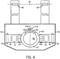
- the laterally rotating portion 112 of the truck drive unit 60 may also include a second slide mechanism(s) that make contact with or interact with the first slide mechanism (e.g., cam 100) as the laterally rotating portion 112 is rotated during a turn.
- the second slide mechanism comprises a bearing 114 that engages the cam 100, such that the bearing(s) 114 would move about a horizontal axis (see arrow 116 in Fig. 4 ) projecting out from the center of rotation of the drive unit 60.
- a single bearing 114 may be used, and may be placed on the truck centerline 118 on the fixed axle side 120 of the drive unit 60 when the steering mechanism 54 is in a straight ahead position.
- bearings or cam mechanism mounted to the fixed axle side of the drive unit allows the mechanism to increase the pressure on the outside castor when the truck is turning. It is to be appreciated that other configurations are considered where a bearing(s) or a cam(s) is mounted opposite of the fixed axle side of the drive unit.
- a bearing 114 allows for a generally smooth interaction between the cam 100 and the bearing 114 as the laterally rotating portion 112 rotates and the bearing 114 contacts and moves, rolls, and/or slides across the cam surface 103.
- the bearing(s) engage the cam 100 on top of the hinged castor wheel, pushing the caster 70 and caster wheel 74 down. This works to prevent the truck from tilting to the outside and keeps the truck more stable. It is to be appreciated that downward pressure on the inside castor may also be reduced in a turn so as to affect movement of one or both the inside and outside caster during a turn.
- one or more second slide mechanisms e.g., bearings 124 and 126
- they may be placed at a predetermined angle or angles away or offset from the centerline 118 of the truck, again on the fixed axle side 120 of the drive unit 60.
- Use of two or more bearings 124, 126 projecting out of the drive unit rather than one allows the stabilization process to begin at a smaller turn angle and/or allows for using smaller cams.
- a single cam 130 is shown coupled to the laterally rotating portion 112 of the truck drive unit 60.
- the cam 130 includes two tapered surfaces 132 and 134 to engage bearings 136 and 138 respectively.
- the bearings 136, 138 are positioned on, or in, the caster plate 86. It is to be appreciated that more than one cam may be used in place of the single cam 130.
- the first slide mechanism may comprise a cam or bearing, and the second slide mechanism may also comprise a cam or a bearing.
- embodiments may use a wide range of systems and methods to adjust the truck stability, and each may be used alone or in combination with other stability controls.
- some embodiments may use an actuator to adjust the caster spring tension in a turn. In this configuration, the caster spring tension may be monitored and controlled to maximize stability.
Landscapes
- Engineering & Computer Science (AREA)
- Transportation (AREA)
- Mechanical Engineering (AREA)
- Structural Engineering (AREA)
- Chemical & Material Sciences (AREA)
- Combustion & Propulsion (AREA)
- Civil Engineering (AREA)
- Life Sciences & Earth Sciences (AREA)
- Geology (AREA)
- Handcart (AREA)
- Vehicle Body Suspensions (AREA)
- Steering-Linkage Mechanisms And Four-Wheel Steering (AREA)
Claims (15)
- Système pour stabiliser un chariot élévateur (50), le système comprenant :une unité d'entraînement (60) rotative. l'unité d'entraînement (60) incluant un pneu d'entraînement (66) dirigeable ;un premier mécanisme coulissant (100) relié à l'unité d'entraînement (60) rotative ;une roulette (70) montée à une plaque de roulette (86) ;un deuxième mécanisme coulissant (114, 124, 126) monté à la plaque de roulette (86);caractérisé en ce que le système comprendun mécanisme de direction (54) relié à l'unité d'entraînement (60) rotative de telle manière que, lors que le mécanisme de direction (54) est déplacé pour diriger le pneu d'entraînement (66) dirigeable, le premier mécanisme coulissant (100) interagit avec le deuxième mécanisme coulissant (114, 124, 126) pour influer une pression sur la roulette (70).
- Système selon la revendication 1, dans lequel la roulette (70) est une roulette extérieure et le premier mécanisme coulissant (100) interagit avec le deuxième mécanisme coulissant (114, 124, 126) pour produire une pression vers le bas sur la roulette extérieure.
- Système selon la revendication 1, dans lequel la roulette (70) est une roulette intérieure et le premier mécanisme coulissant (100) interagit avec le deuxième mécanisme coulissant (114, 124, 126) pour réduire une pression vers le bas sur la roulette intérieure.
- Système selon la revendication 2, comprenant en outre une liaison articulée (90) pour connecter la plaque de roulette (86) avec le chariot élévateur (50) de telle manière que la liaison articulée (90) permet que la pression vers le bas sur la roulette (70) fasse pivoter la roulette (70) vers le bas en direction d'un sol.
- Système selon l'une quelconque des revendications 1 à 4, dans lequel le premier mécanisme coulissant (100) comprend un parmi une came et un palier et le deuxième mécanisme coulissant (114, 124, 126) comprend l'autre parmi la came et le palier.
- Système selon l'une quelconque des revendications 1 à 5, dans lequel l'unité d'entraînement (60) rotative généralement est positionnée entre deux roulettes (70).
- Système selon l'une quelconque des revendications 1 à 6, dans lequel le chariot élévateur (50), en outre, comprend une fourche (52) porteuse de charges, la fourche (52) porteuse de charges incluant des roues porteuse de charges, les roues porteuses de charges étant disposées comme essieu porteur de charges.
- Système selon la revendication 7, dans lequel le premier mécanisme coulissant (100) est monté sur le côté faisant face à l'essieu porteur de charges de l'unité d'entraînement (60) rotative.
- Système selon la revendication 1, dans lequel
le premier mécanisme coulissant (100) comprend un mécanisme coulissant sur le côté gauche et un mécanisme coulissant sur le côté droit ;
la roulette (70) comprend une roulette gauche montée à une plaque de roulette gauche et une roulette droite montée à une plaque de roulette droite ;
le deuxième mécanisme coulissant (114, 124, 126) comprend un mécanisme coulissant de la roulette gauche monté à la plaque de roulette gauche et un mécanisme coulissant de la roulette droite monté à la plaque de roulette droite ; et
dans lequel, lorsque le mécanisme de direction (54) est déplacé pour tourner le chariot élévateur (50) à gauche, le mécanisme coulissant sur le côté droit interagit avec le mécanisme coulissant de la roulette droite pour produire une pression vers le bas sur la roulette droite. - Système selon la revendication 9, comprenant en outre une liaison articulée gauche pour connecter la plaque de roulette gauche avec le chariot élévateur (50) ; et
une liaison articulée droite pour connecter la plaque de roulette droite avec le chariot élévateur (50). - Système selon la revendication 9 ou 10, comprenant en outre une fourche porteuse de charges, la fourche porteuse de charges incluant des roues porteuse de charges, les roues porteuses de charges étant disposées comme essieu porteur de charges.
- Système selon la revendication 11, dans lequel le mécanisme coulissant gauche et le mécanisme coulissant droit sont montés sur le côté faisant face á l'essieu porteur de charges de l'unité d'entraînement rotative.
- Procédé pour stabiliser un chariot élévateur (50), le procédé comprenant :prévoir une unité d'entraînement (60) rotative, l'unité d'entraînement (60) incluant un pneu d'entraînement (66) dirigeable ;prévoir un premier mécanisme coulissant (100) relié à l'unité d'entraînement (60) rotative ;prévoir une roulette (70) montée à une plaque de roulette (86) ;prévoir un deuxième mécanisme coulissant (114, 124, 126) monté à la plaque de roulette (86) ;prévoir un mécanisme de direction (54) relié à l'unité d'entraînement (60) rotative, le mécanisme de direction (54) servant à diriger le pneu d'entraînement (66) dirigeable et provoquant que le premier mécanisme coulissant (100) interagisse avec le deuxième mécanisme coulissant (114, 124, 126) ; et influer une pression sur la roulette (70).
- Procédé selon la revendication 13, dans lequel la roulette (70) est une roulette extérieure et influer la pression comprend produire une pression vers le bas sur la roulette extérieure.
- Procédé selon la revendication 13, dans lequel la roulette (70) est une roulette intérieure et influer la pression comprend réduire une pression vers le bas sur la roulette intérieure.
Applications Claiming Priority (1)
| Application Number | Priority Date | Filing Date | Title |
|---|---|---|---|
| US13/424,886 US8763990B2 (en) | 2012-03-20 | 2012-03-20 | Turn stability systems and methods for lift trucks |
Publications (3)
| Publication Number | Publication Date |
|---|---|
| EP2641809A2 EP2641809A2 (fr) | 2013-09-25 |
| EP2641809A3 EP2641809A3 (fr) | 2017-12-27 |
| EP2641809B1 true EP2641809B1 (fr) | 2020-07-29 |
Family
ID=47563266
Family Applications (1)
| Application Number | Title | Priority Date | Filing Date |
|---|---|---|---|
| EP13151790.6A Active EP2641809B1 (fr) | 2012-03-20 | 2013-01-18 | Systèmes et procédés de stabilisation de chariots élévateurs lors du braquage |
Country Status (5)
| Country | Link |
|---|---|
| US (1) | US8763990B2 (fr) |
| EP (1) | EP2641809B1 (fr) |
| CN (1) | CN103318255B (fr) |
| AU (1) | AU2013200185B2 (fr) |
| CA (1) | CA2804145C (fr) |
Families Citing this family (11)
| Publication number | Priority date | Publication date | Assignee | Title |
|---|---|---|---|---|
| US8894037B1 (en) * | 2011-07-20 | 2014-11-25 | Jeffrey L. Brauer | Lift truck platform apparatus and methods for transporting rolling racks |
| CA2820695A1 (fr) * | 2013-07-10 | 2015-01-10 | J.H. Ryder Machinery Limited | Transpalette |
| US9593003B2 (en) * | 2014-04-01 | 2017-03-14 | The Raymond Corporation | Caster wheel with constant force mechanism |
| US10315900B2 (en) * | 2014-04-01 | 2019-06-11 | The Raymond Corporation | Caster wheel with constant force mechanism |
| WO2019035059A1 (fr) * | 2017-08-16 | 2019-02-21 | Newell Gregory | Dispositif de déplacement de chariot sans attelage |
| EP3459814B1 (fr) | 2017-09-25 | 2022-04-13 | Mitsubishi Logisnext Europe AB | Dispositif de roue de support de stabilisation et chariot de manutention comprenant un tel dispositif de roue de support |
| EP3470297B1 (fr) * | 2017-10-10 | 2022-05-11 | Mitsubishi Logisnext Europe AB | Unité d'entraînement pour camion industriel et chariot industriel comportant une telle unité d'entraînement |
| CN108773432B (zh) * | 2018-06-26 | 2023-06-27 | 深圳市功夫机器人有限公司 | 悬挂结构和agv |
| US10737922B2 (en) | 2018-08-08 | 2020-08-11 | International Business Machines Corporation | Mechanically actuated load stabilizer for pallet jacks |
| CN111056497B (zh) * | 2019-12-26 | 2021-05-28 | 杭叉集团股份有限公司 | 一种后驱式叉车防滑控制方法及其控制系统 |
| GB2595845B (en) * | 2020-05-01 | 2024-03-06 | M Mover Holdings Ltd | Load transporting apparatus |
Family Cites Families (88)
| Publication number | Priority date | Publication date | Assignee | Title |
|---|---|---|---|---|
| US2438571A (en) * | 1944-05-27 | 1948-03-30 | Jr Glenway Maxon | Stabilizer for spring mounted vehicles |
| US2614643A (en) * | 1947-06-04 | 1952-10-21 | Yale & Towne Mfg Co | Stabilizer for lift trucks |
| DE957377C (de) | 1953-10-25 | 1957-01-31 | Miag Muehlenbau & Ind Gmbh | Hubvorrichtung fuer Flurfoerdergeraete |
| US2982395A (en) | 1958-12-08 | 1961-05-02 | Harbor Boat Building Company | Reusable shipping container |
| US3031024A (en) | 1959-07-23 | 1962-04-24 | Yale & Towne Mfg Co | All directional industrial truck |
| US3067839A (en) | 1961-03-29 | 1962-12-11 | Raymond Corp | Material handling vehicle |
| US3504889A (en) | 1968-03-18 | 1970-04-07 | Midland Ross Corp | Portable vehicle lift |
| US3672634A (en) | 1969-07-28 | 1972-06-27 | Ezy Way Mfg & Sales Co | Lifting apparatus |
| US3918597A (en) | 1971-10-14 | 1975-11-11 | Lee Inventions Inc | Method of moving a heavy load |
| US4037739A (en) | 1974-05-07 | 1977-07-26 | Lee Inventions, Inc. | Moving system with integral casters |
| JPS57160708A (en) | 1981-03-27 | 1982-10-04 | Nissan Motor Co Ltd | Rear wheel suspension for one-sided wheel drive type four-point support car |
| US4509127A (en) | 1981-03-31 | 1985-04-02 | Kabushiki Kaisha Toyoda Jidoh Shokki Seisakusho | Control device for loading and unloading mechanism |
| JPS58167214A (ja) | 1982-03-27 | 1983-10-03 | Toyoda Autom Loom Works Ltd | 産業車両における車軸固定装置 |
| US4530492A (en) | 1983-05-25 | 1985-07-23 | Bork Robert L | Apparatus for supporting vehicle body parts |
| US4534433A (en) * | 1983-09-19 | 1985-08-13 | The Raymond Corporation | Material handling vehicle |
| FR2606765B1 (fr) * | 1986-11-13 | 1989-03-03 | Loc Manutention | Mecanisme repartiteur d'appui pour chariots de manutention et de levage notamment les transpalettes et les gerbeurs |
| BR8707700A (pt) | 1987-03-18 | 1989-10-03 | Monroe Auto Equipment Co | Processo e aparelho para absorver choques mecanicos |
| US4771531A (en) * | 1987-05-13 | 1988-09-20 | Rufus Asher | Device for lifting vehicle wheels |
| US5107969A (en) | 1987-09-17 | 1992-04-28 | Alfred Teves Gmbh | Controllable vibration damper |
| FR2667546B1 (fr) * | 1990-10-09 | 1993-01-08 | Loc Manutention | Chariot a plate-forme a stabilite renforcee. |
| US5289902A (en) | 1991-10-29 | 1994-03-01 | Kabushiki Kaisha Toshiba | Elevator |
| US5269501A (en) | 1992-12-03 | 1993-12-14 | Hein-Werner Corporation | Vehicle and vehicle parts transportation system |
| JPH06263145A (ja) | 1993-03-10 | 1994-09-20 | Pfu Ltd | スクラップ箱、スクラップ排出装置及び排出方法 |
| US5480275A (en) * | 1993-10-18 | 1996-01-02 | Taylor Iron-Machine Works, Inc. | Fork lift truck |
| FR2716878B1 (fr) * | 1994-03-04 | 1996-04-26 | Mic | Chariot de manutention avec roues stabilisatrices. |
| JP2736607B2 (ja) | 1994-05-30 | 1998-04-02 | 浅香工業株式会社 | ロールボックスの格納装置 |
| JPH0899513A (ja) | 1994-09-29 | 1996-04-16 | Unisia Jecs Corp | 車両懸架装置 |
| US5647600A (en) | 1995-01-09 | 1997-07-15 | American Wholesale Beverage Co., Inc. | Cart |
| US5579859A (en) | 1995-02-10 | 1996-12-03 | Crown Equipment Corporation | Isolated floor for material handling vehicle |
| IT1281790B1 (it) * | 1995-05-03 | 1998-03-03 | Carer Snc Dell Ing Angelo Gaet | Carrello elevatore a quattro ruote con stretto raggio di sterzata e stabilita' migliorata |
| US5628377A (en) | 1995-06-16 | 1997-05-13 | M I C, Societe Anonyme | Goods-handling cart with stabilizing wheels |
| JPH0986610A (ja) | 1995-09-26 | 1997-03-31 | Murata Mach Ltd | カゴ台車用自動倉庫 |
| JP3317112B2 (ja) | 1995-11-20 | 2002-08-26 | 株式会社豊田中央研究所 | スピン限界検出装置及びスピン防止装置 |
| EP0806715B1 (fr) | 1995-11-30 | 1999-03-17 | Siemag Transplan Gmbh | Procédé pour la régulation d'un appareil de desserte de rayonnages commandé par ordinateur |
| US5878851A (en) | 1996-07-02 | 1999-03-09 | Lord Corporation | Controllable vibration apparatus |
| DE19641192C2 (de) | 1996-09-24 | 2002-10-31 | Siemens Ag | Handhabungsgerät, insbesondere Regalbediengerät |
| US5993358A (en) | 1997-03-05 | 1999-11-30 | Lord Corporation | Controllable platform suspension system for treadmill decks and the like and devices therefor |
| JPH1120442A (ja) | 1997-07-08 | 1999-01-26 | Toyota Autom Loom Works Ltd | 産業車両用揺動制御装置 |
| CA2304139C (fr) | 1997-09-30 | 2008-11-18 | Crown Equipment Corporation | Systeme de freinage intelligent pour vehicules de manutention de matieres |
| JPH11100200A (ja) | 1997-09-30 | 1999-04-13 | Komatsu Forklift Co Ltd | フォークリフトトラックの懸架装置 |
| JPH11165998A (ja) | 1997-12-04 | 1999-06-22 | Toyota Autom Loom Works Ltd | 産業車両の車体揺動制御装置及び産業車両 |
| DE19802119A1 (de) | 1998-01-21 | 1999-07-22 | Still Wagner Gmbh & Co Kg | Flurförderzeug mit einer Hubvorrichtung |
| JP3601294B2 (ja) | 1998-04-22 | 2004-12-15 | 株式会社豊田自動織機 | 産業車両の車体揺動制御装置 |
| JP2000062428A (ja) | 1998-08-21 | 2000-02-29 | Toyota Autom Loom Works Ltd | 産業車両の車体揺動制御装置 |
| JP4245722B2 (ja) | 1999-02-17 | 2009-04-02 | 住友ナコ マテリアル ハンドリング株式会社 | フォークリフトの車軸揺動装置 |
| FR2796887B1 (fr) | 1999-07-27 | 2002-11-15 | Lohr Ind | Dispositif d'amortissement des mouvements de lacet d'une remorque routiere tractee par un vehicule a moteur |
| US6517094B1 (en) | 2000-03-30 | 2003-02-11 | American Axle & Manufacturing, Inc. | Hydraulic anti-roll suspension system for motor vehicles |
| US6279199B1 (en) | 2000-06-13 | 2001-08-28 | Ross Design & Engineering, Inc. | Vertically adjustable caster |
| DE10033801A1 (de) | 2000-07-12 | 2002-01-24 | Fiat Om Carrelli Elevatori | Flurförderzug |
| US7070028B2 (en) | 2001-02-07 | 2006-07-04 | Tenneco Automotive Operating Company Inc. | Frequency dependent damper |
| US6601825B2 (en) | 2001-02-22 | 2003-08-05 | Alum-A-Lift, Inc. | Portable and demountable lifting device |
| US6499184B2 (en) | 2001-05-14 | 2002-12-31 | Ross Design & Engineering, Inc. | Elastomeric biased caster |
| DE10126933B4 (de) | 2001-06-01 | 2004-08-26 | Continental Aktiengesellschaft | Verfahren zur Regelung oder Steuerung der Dämpferkraft verstellbarer Dämpfer an Fahrzeugen |
| JP2002370899A (ja) | 2001-06-14 | 2002-12-24 | Mitsubishi Heavy Ind Ltd | フォークリフト車両 |
| GB2379434B (en) | 2001-09-10 | 2004-09-22 | Lansing Linde Ltd | Industrial truck with a lifting frame |
| FR2837809B1 (fr) | 2002-03-29 | 2004-11-12 | Manitou Bf | Chariot elevateur a portee variable a trois roues |
| JP2004001941A (ja) | 2002-05-31 | 2004-01-08 | Tcm Corp | マスト装置 |
| AU2003279045A1 (en) | 2002-10-02 | 2004-04-23 | Harlan Silverstein | Pneumatic locking swivel caster |
| JP2004269236A (ja) | 2003-03-12 | 2004-09-30 | Nippon Yusoki Co Ltd | フォークリフト |
| US7008166B1 (en) | 2003-06-05 | 2006-03-07 | Honda Giken Kogyo Kabushiki Kaisha | Door lifting apparatus and method |
| US7073643B2 (en) | 2003-10-27 | 2006-07-11 | Tenneco Automotive Operating Company Inc. | Compensated rod for a frequency dependent damper shock absorber |
| US20050173849A1 (en) | 2004-02-10 | 2005-08-11 | Bart Vandewal | Electronically controlled frequency dependent damping |
| DE102004019072A1 (de) | 2004-04-20 | 2005-11-17 | Om Carrelli Elevatori S.P.A. | Flurförderzeug, insbesondere Gabelhubwagen |
| US20060138733A1 (en) | 2004-08-11 | 2006-06-29 | Luke Clauson | Suspension adjustment system |
| DE102004048519A1 (de) | 2004-08-23 | 2006-03-02 | Sandt Logistik Gmbh | Antriebsregelung für ein Regalbediengerät |
| US20060182578A1 (en) | 2005-01-26 | 2006-08-17 | Escalera, Inc. | Cart & dual use ramp for console copier relocation |
| JP4546308B2 (ja) | 2005-03-30 | 2010-09-15 | 本田技研工業株式会社 | 可変減衰力ダンパーの制御装置 |
| US7770904B2 (en) | 2005-04-14 | 2010-08-10 | Nmhg Oregon, Llc | Stability system for an industrial vehicle |
| CA2559463A1 (fr) | 2005-09-15 | 2007-03-15 | Dynatool Industries Inc. | Roue pivotante a blocage motorise |
| DE102005053264A1 (de) | 2005-11-08 | 2007-05-10 | Still Gmbh | Mobile Arbeitsmaschine mit einem Fahrerplatz |
| SE531618C2 (sv) | 2006-02-23 | 2009-06-09 | Oehlins Racing Ab | Elektrisk styrd trycksatt dämpare |
| US20070231113A1 (en) | 2006-03-10 | 2007-10-04 | Mcgurn Arthur S | Apparatus and method for lifting and transporting a container with an independent mechanized unit |
| CN2889874Y (zh) | 2006-03-23 | 2007-04-18 | 历德奎 | 立式弓片减振器 |
| US7823862B2 (en) * | 2006-05-03 | 2010-11-02 | Hussam Wakil | Toilet lift and transport apparatus |
| US20090312875A1 (en) | 2006-07-12 | 2009-12-17 | Lasse Lehtonen | Method and an arrangement for dampening vibrations in a mast structure |
| JP2008081261A (ja) | 2006-09-28 | 2008-04-10 | Toyota Industries Corp | フォークリフトにおける振動抑制装置 |
| US7888901B2 (en) | 2006-11-15 | 2011-02-15 | Honeywell International Inc. | Active human-machine interface system including an electrically controllable damper |
| DE102007015488A1 (de) | 2007-03-30 | 2008-10-02 | Still Wagner Gmbh | Schwingungskompensation am Hubgerüst eines Flurförderzeugs |
| DE102007038016A1 (de) | 2007-08-10 | 2009-02-12 | Iveco Magirus Ag | Drehleiter |
| US7905555B2 (en) | 2007-08-16 | 2011-03-15 | Global Polymer Industries, Inc. | Yaw control system for a vehicle-trailer combination |
| DE102007045211B4 (de) | 2007-09-21 | 2010-11-11 | Ford Global Technologies, LLC, Dearborn | Verfahren und eine Vorrichtung zum elektrisch gesteuerten Unterstützen einer Fahrzeugbewegung eines Fahrzeugs |
| US7896358B2 (en) | 2007-10-25 | 2011-03-01 | The Raymond Corporation | Magneto-rheological inertial damping system for lift trucks |
| CN201136759Y (zh) * | 2007-11-26 | 2008-10-22 | 华为技术有限公司 | 一种叉车 |
| DE102008020595B4 (de) | 2008-04-24 | 2022-02-10 | Linde Material Handling Gmbh | Verfahren zur Schwingungsdämpfung bei Flurförderzeugen |
| US8967648B2 (en) | 2009-03-12 | 2015-03-03 | Arvinmeritor Technology, Llc | Continuous force control for dual air spring configuration |
| US8140228B2 (en) | 2009-03-27 | 2012-03-20 | The Raymond Corporation | System and method for dynamically maintaining the stability of a material handling vehicle having a vertical lift |
| KR102072792B1 (ko) | 2010-03-12 | 2020-02-03 | 심보틱 엘엘씨 | 보충 및 주문 이행 시스템 |
| DE102010016062A1 (de) | 2010-03-22 | 2011-09-22 | Technische Universität München | Dämpfung oder Vermeidung von Schwingungen bei Flurförderzeugen |
-
2012
- 2012-03-20 US US13/424,886 patent/US8763990B2/en active Active
-
2013
- 2013-01-14 AU AU2013200185A patent/AU2013200185B2/en active Active
- 2013-01-18 CN CN201310071256.7A patent/CN103318255B/zh active Active
- 2013-01-18 EP EP13151790.6A patent/EP2641809B1/fr active Active
- 2013-01-25 CA CA2804145A patent/CA2804145C/fr active Active
Non-Patent Citations (1)
| Title |
|---|
| None * |
Also Published As
| Publication number | Publication date |
|---|---|
| CA2804145A1 (fr) | 2013-09-20 |
| CN103318255A (zh) | 2013-09-25 |
| CN103318255B (zh) | 2016-12-28 |
| US8763990B2 (en) | 2014-07-01 |
| CA2804145C (fr) | 2019-04-30 |
| AU2013200185A1 (en) | 2013-10-17 |
| US20130248787A1 (en) | 2013-09-26 |
| AU2013200185B2 (en) | 2014-07-10 |
| EP2641809A3 (fr) | 2017-12-27 |
| EP2641809A2 (fr) | 2013-09-25 |
Similar Documents
| Publication | Publication Date | Title |
|---|---|---|
| EP2641809B1 (fr) | Systèmes et procédés de stabilisation de chariots élévateurs lors du braquage | |
| CN100393607C (zh) | 具有行进驱动装置和乘员位置的工业卡车 | |
| CN112061287A (zh) | 用于多轮式侧倾车辆的侧倾机构 | |
| KR20110034642A (ko) | 개선된 수륙양용차 | |
| CA2658310A1 (fr) | Corps mobile du type a roues pouvant etre inversees | |
| JP2004224333A (ja) | 車輌の懸架装置 | |
| US20060254841A1 (en) | Vehicle with adjustable axle system for actively maintaining stability | |
| US20140083785A1 (en) | Steerable wheel assembly for a vehicle, and vehicle including such an assembly | |
| JP7375631B2 (ja) | 三列車輪車両 | |
| JP7352190B2 (ja) | 三列車輪車両 | |
| KR101533932B1 (ko) | 회전 주행의 안정성이 향상된 이륜차 | |
| WO2007087255A2 (fr) | Systeme de stabilisation pour motocyclette | |
| JP7181507B2 (ja) | 三列車輪車両 | |
| EP1799472B1 (fr) | Systeme de commande de l'inclinaison et de l'alignement d'un vehicule | |
| EP3459814B1 (fr) | Dispositif de roue de support de stabilisation et chariot de manutention comprenant un tel dispositif de roue de support | |
| CN210149440U (zh) | 用于车辆的天平式重心控制装置 | |
| JP2018024388A (ja) | 走行装置 | |
| JP2021142963A (ja) | 三列車輪車両 | |
| JP2010163147A (ja) | 自転車用積載時姿勢安定装置 | |
| JP2006160406A (ja) | 荷役車両 | |
| JP3109280B2 (ja) | 後輪操舵車両における揺動制御構造 | |
| US20180281887A1 (en) | Vehicle | |
| CN212098325U (zh) | 驱动系统及自动导引运输车 | |
| JP5355189B2 (ja) | サスペンション装置 | |
| EP3470297B1 (fr) | Unité d'entraînement pour camion industriel et chariot industriel comportant une telle unité d'entraînement |
Legal Events
| Date | Code | Title | Description |
|---|---|---|---|
| PUAI | Public reference made under article 153(3) epc to a published international application that has entered the european phase |
Free format text: ORIGINAL CODE: 0009012 |
|
| AK | Designated contracting states |
Kind code of ref document: A2 Designated state(s): AL AT BE BG CH CY CZ DE DK EE ES FI FR GB GR HR HU IE IS IT LI LT LU LV MC MK MT NL NO PL PT RO RS SE SI SK SM TR |
|
| AX | Request for extension of the european patent |
Extension state: BA ME |
|
| PUAL | Search report despatched |
Free format text: ORIGINAL CODE: 0009013 |
|
| AK | Designated contracting states |
Kind code of ref document: A3 Designated state(s): AL AT BE BG CH CY CZ DE DK EE ES FI FR GB GR HR HU IE IS IT LI LT LU LV MC MK MT NL NO PL PT RO RS SE SI SK SM TR |
|
| AX | Request for extension of the european patent |
Extension state: BA ME |
|
| RIC1 | Information provided on ipc code assigned before grant |
Ipc: B62B 3/06 20060101AFI20171121BHEP |
|
| STAA | Information on the status of an ep patent application or granted ep patent |
Free format text: STATUS: REQUEST FOR EXAMINATION WAS MADE |
|
| 17P | Request for examination filed |
Effective date: 20180220 |
|
| RBV | Designated contracting states (corrected) |
Designated state(s): AL AT BE BG CH CY CZ DE DK EE ES FI FR GB GR HR HU IE IS IT LI LT LU LV MC MK MT NL NO PL PT RO RS SE SI SK SM TR |
|
| GRAP | Despatch of communication of intention to grant a patent |
Free format text: ORIGINAL CODE: EPIDOSNIGR1 |
|
| STAA | Information on the status of an ep patent application or granted ep patent |
Free format text: STATUS: GRANT OF PATENT IS INTENDED |
|
| INTG | Intention to grant announced |
Effective date: 20200303 |
|
| GRAS | Grant fee paid |
Free format text: ORIGINAL CODE: EPIDOSNIGR3 |
|
| GRAA | (expected) grant |
Free format text: ORIGINAL CODE: 0009210 |
|
| STAA | Information on the status of an ep patent application or granted ep patent |
Free format text: STATUS: THE PATENT HAS BEEN GRANTED |
|
| AK | Designated contracting states |
Kind code of ref document: B1 Designated state(s): AL AT BE BG CH CY CZ DE DK EE ES FI FR GB GR HR HU IE IS IT LI LT LU LV MC MK MT NL NO PL PT RO RS SE SI SK SM TR |
|
| REG | Reference to a national code |
Ref country code: GB Ref legal event code: FG4D |
|
| REG | Reference to a national code |
Ref country code: CH Ref legal event code: EP |
|
| REG | Reference to a national code |
Ref country code: AT Ref legal event code: REF Ref document number: 1295453 Country of ref document: AT Kind code of ref document: T Effective date: 20200815 |
|
| REG | Reference to a national code |
Ref country code: IE Ref legal event code: FG4D |
|
| REG | Reference to a national code |
Ref country code: DE Ref legal event code: R096 Ref document number: 602013071053 Country of ref document: DE |
|
| REG | Reference to a national code |
Ref country code: SE Ref legal event code: TRGR |
|
| REG | Reference to a national code |
Ref country code: LT Ref legal event code: MG4D |
|
| REG | Reference to a national code |
Ref country code: NL Ref legal event code: MP Effective date: 20200729 |
|
| REG | Reference to a national code |
Ref country code: AT Ref legal event code: MK05 Ref document number: 1295453 Country of ref document: AT Kind code of ref document: T Effective date: 20200729 |
|
| PG25 | Lapsed in a contracting state [announced via postgrant information from national office to epo] |
Ref country code: FI Free format text: LAPSE BECAUSE OF FAILURE TO SUBMIT A TRANSLATION OF THE DESCRIPTION OR TO PAY THE FEE WITHIN THE PRESCRIBED TIME-LIMIT Effective date: 20200729 Ref country code: PT Free format text: LAPSE BECAUSE OF FAILURE TO SUBMIT A TRANSLATION OF THE DESCRIPTION OR TO PAY THE FEE WITHIN THE PRESCRIBED TIME-LIMIT Effective date: 20201130 Ref country code: BG Free format text: LAPSE BECAUSE OF FAILURE TO SUBMIT A TRANSLATION OF THE DESCRIPTION OR TO PAY THE FEE WITHIN THE PRESCRIBED TIME-LIMIT Effective date: 20201029 Ref country code: GR Free format text: LAPSE BECAUSE OF FAILURE TO SUBMIT A TRANSLATION OF THE DESCRIPTION OR TO PAY THE FEE WITHIN THE PRESCRIBED TIME-LIMIT Effective date: 20201030 Ref country code: LT Free format text: LAPSE BECAUSE OF FAILURE TO SUBMIT A TRANSLATION OF THE DESCRIPTION OR TO PAY THE FEE WITHIN THE PRESCRIBED TIME-LIMIT Effective date: 20200729 Ref country code: HR Free format text: LAPSE BECAUSE OF FAILURE TO SUBMIT A TRANSLATION OF THE DESCRIPTION OR TO PAY THE FEE WITHIN THE PRESCRIBED TIME-LIMIT Effective date: 20200729 Ref country code: AT Free format text: LAPSE BECAUSE OF FAILURE TO SUBMIT A TRANSLATION OF THE DESCRIPTION OR TO PAY THE FEE WITHIN THE PRESCRIBED TIME-LIMIT Effective date: 20200729 Ref country code: ES Free format text: LAPSE BECAUSE OF FAILURE TO SUBMIT A TRANSLATION OF THE DESCRIPTION OR TO PAY THE FEE WITHIN THE PRESCRIBED TIME-LIMIT Effective date: 20200729 Ref country code: NO Free format text: LAPSE BECAUSE OF FAILURE TO SUBMIT A TRANSLATION OF THE DESCRIPTION OR TO PAY THE FEE WITHIN THE PRESCRIBED TIME-LIMIT Effective date: 20201029 |
|
| PG25 | Lapsed in a contracting state [announced via postgrant information from national office to epo] |
Ref country code: IS Free format text: LAPSE BECAUSE OF FAILURE TO SUBMIT A TRANSLATION OF THE DESCRIPTION OR TO PAY THE FEE WITHIN THE PRESCRIBED TIME-LIMIT Effective date: 20201129 Ref country code: PL Free format text: LAPSE BECAUSE OF FAILURE TO SUBMIT A TRANSLATION OF THE DESCRIPTION OR TO PAY THE FEE WITHIN THE PRESCRIBED TIME-LIMIT Effective date: 20200729 Ref country code: RS Free format text: LAPSE BECAUSE OF FAILURE TO SUBMIT A TRANSLATION OF THE DESCRIPTION OR TO PAY THE FEE WITHIN THE PRESCRIBED TIME-LIMIT Effective date: 20200729 Ref country code: LV Free format text: LAPSE BECAUSE OF FAILURE TO SUBMIT A TRANSLATION OF THE DESCRIPTION OR TO PAY THE FEE WITHIN THE PRESCRIBED TIME-LIMIT Effective date: 20200729 |
|
| PG25 | Lapsed in a contracting state [announced via postgrant information from national office to epo] |
Ref country code: NL Free format text: LAPSE BECAUSE OF FAILURE TO SUBMIT A TRANSLATION OF THE DESCRIPTION OR TO PAY THE FEE WITHIN THE PRESCRIBED TIME-LIMIT Effective date: 20200729 |
|
| PG25 | Lapsed in a contracting state [announced via postgrant information from national office to epo] |
Ref country code: RO Free format text: LAPSE BECAUSE OF FAILURE TO SUBMIT A TRANSLATION OF THE DESCRIPTION OR TO PAY THE FEE WITHIN THE PRESCRIBED TIME-LIMIT Effective date: 20200729 Ref country code: SM Free format text: LAPSE BECAUSE OF FAILURE TO SUBMIT A TRANSLATION OF THE DESCRIPTION OR TO PAY THE FEE WITHIN THE PRESCRIBED TIME-LIMIT Effective date: 20200729 Ref country code: CZ Free format text: LAPSE BECAUSE OF FAILURE TO SUBMIT A TRANSLATION OF THE DESCRIPTION OR TO PAY THE FEE WITHIN THE PRESCRIBED TIME-LIMIT Effective date: 20200729 Ref country code: DK Free format text: LAPSE BECAUSE OF FAILURE TO SUBMIT A TRANSLATION OF THE DESCRIPTION OR TO PAY THE FEE WITHIN THE PRESCRIBED TIME-LIMIT Effective date: 20200729 Ref country code: EE Free format text: LAPSE BECAUSE OF FAILURE TO SUBMIT A TRANSLATION OF THE DESCRIPTION OR TO PAY THE FEE WITHIN THE PRESCRIBED TIME-LIMIT Effective date: 20200729 |
|
| REG | Reference to a national code |
Ref country code: DE Ref legal event code: R097 Ref document number: 602013071053 Country of ref document: DE |
|
| PG25 | Lapsed in a contracting state [announced via postgrant information from national office to epo] |
Ref country code: AL Free format text: LAPSE BECAUSE OF FAILURE TO SUBMIT A TRANSLATION OF THE DESCRIPTION OR TO PAY THE FEE WITHIN THE PRESCRIBED TIME-LIMIT Effective date: 20200729 |
|
| PLBE | No opposition filed within time limit |
Free format text: ORIGINAL CODE: 0009261 |
|
| STAA | Information on the status of an ep patent application or granted ep patent |
Free format text: STATUS: NO OPPOSITION FILED WITHIN TIME LIMIT |
|
| PG25 | Lapsed in a contracting state [announced via postgrant information from national office to epo] |
Ref country code: SK Free format text: LAPSE BECAUSE OF FAILURE TO SUBMIT A TRANSLATION OF THE DESCRIPTION OR TO PAY THE FEE WITHIN THE PRESCRIBED TIME-LIMIT Effective date: 20200729 |
|
| 26N | No opposition filed |
Effective date: 20210430 |
|
| PG25 | Lapsed in a contracting state [announced via postgrant information from national office to epo] |
Ref country code: SI Free format text: LAPSE BECAUSE OF FAILURE TO SUBMIT A TRANSLATION OF THE DESCRIPTION OR TO PAY THE FEE WITHIN THE PRESCRIBED TIME-LIMIT Effective date: 20200729 Ref country code: MC Free format text: LAPSE BECAUSE OF FAILURE TO SUBMIT A TRANSLATION OF THE DESCRIPTION OR TO PAY THE FEE WITHIN THE PRESCRIBED TIME-LIMIT Effective date: 20200729 |
|
| REG | Reference to a national code |
Ref country code: CH Ref legal event code: PL |
|
| PG25 | Lapsed in a contracting state [announced via postgrant information from national office to epo] |
Ref country code: LU Free format text: LAPSE BECAUSE OF NON-PAYMENT OF DUE FEES Effective date: 20210118 |
|
| REG | Reference to a national code |
Ref country code: BE Ref legal event code: MM Effective date: 20210131 |
|
| PG25 | Lapsed in a contracting state [announced via postgrant information from national office to epo] |
Ref country code: CH Free format text: LAPSE BECAUSE OF NON-PAYMENT OF DUE FEES Effective date: 20210131 Ref country code: LI Free format text: LAPSE BECAUSE OF NON-PAYMENT OF DUE FEES Effective date: 20210131 |
|
| PG25 | Lapsed in a contracting state [announced via postgrant information from national office to epo] |
Ref country code: IE Free format text: LAPSE BECAUSE OF NON-PAYMENT OF DUE FEES Effective date: 20210118 |
|
| PG25 | Lapsed in a contracting state [announced via postgrant information from national office to epo] |
Ref country code: BE Free format text: LAPSE BECAUSE OF NON-PAYMENT OF DUE FEES Effective date: 20210131 |
|
| PG25 | Lapsed in a contracting state [announced via postgrant information from national office to epo] |
Ref country code: HU Free format text: LAPSE BECAUSE OF FAILURE TO SUBMIT A TRANSLATION OF THE DESCRIPTION OR TO PAY THE FEE WITHIN THE PRESCRIBED TIME-LIMIT; INVALID AB INITIO Effective date: 20130118 |
|
| PG25 | Lapsed in a contracting state [announced via postgrant information from national office to epo] |
Ref country code: CY Free format text: LAPSE BECAUSE OF FAILURE TO SUBMIT A TRANSLATION OF THE DESCRIPTION OR TO PAY THE FEE WITHIN THE PRESCRIBED TIME-LIMIT Effective date: 20200729 |
|
| P01 | Opt-out of the competence of the unified patent court (upc) registered |
Effective date: 20230530 |
|
| PGFP | Annual fee paid to national office [announced via postgrant information from national office to epo] |
Ref country code: GB Payment date: 20231130 Year of fee payment: 12 |
|
| PGFP | Annual fee paid to national office [announced via postgrant information from national office to epo] |
Ref country code: SE Payment date: 20231213 Year of fee payment: 12 Ref country code: FR Payment date: 20231212 Year of fee payment: 12 |
|
| PG25 | Lapsed in a contracting state [announced via postgrant information from national office to epo] |
Ref country code: MK Free format text: LAPSE BECAUSE OF FAILURE TO SUBMIT A TRANSLATION OF THE DESCRIPTION OR TO PAY THE FEE WITHIN THE PRESCRIBED TIME-LIMIT Effective date: 20200729 |
|
| PGFP | Annual fee paid to national office [announced via postgrant information from national office to epo] |
Ref country code: DE Payment date: 20231205 Year of fee payment: 12 |
|
| PGFP | Annual fee paid to national office [announced via postgrant information from national office to epo] |
Ref country code: IT Payment date: 20231212 Year of fee payment: 12 |