EP2632750B1 - Fugenlose heckklappe - Google Patents
Fugenlose heckklappe Download PDFInfo
- Publication number
- EP2632750B1 EP2632750B1 EP11776742.6A EP11776742A EP2632750B1 EP 2632750 B1 EP2632750 B1 EP 2632750B1 EP 11776742 A EP11776742 A EP 11776742A EP 2632750 B1 EP2632750 B1 EP 2632750B1
- Authority
- EP
- European Patent Office
- Prior art keywords
- tailgate
- carrier
- layers
- layer
- weight
- Prior art date
- Legal status (The legal status is an assumption and is not a legal conclusion. Google has not performed a legal analysis and makes no representation as to the accuracy of the status listed.)
- Active
Links
Images


Classifications
-
- B—PERFORMING OPERATIONS; TRANSPORTING
- B60—VEHICLES IN GENERAL
- B60J—WINDOWS, WINDSCREENS, NON-FIXED ROOFS, DOORS, OR SIMILAR DEVICES FOR VEHICLES; REMOVABLE EXTERNAL PROTECTIVE COVERINGS SPECIALLY ADAPTED FOR VEHICLES
- B60J5/00—Doors
- B60J5/10—Doors arranged at the vehicle rear
-
- B—PERFORMING OPERATIONS; TRANSPORTING
- B32—LAYERED PRODUCTS
- B32B—LAYERED PRODUCTS, i.e. PRODUCTS BUILT-UP OF STRATA OF FLAT OR NON-FLAT, e.g. CELLULAR OR HONEYCOMB, FORM
- B32B27/00—Layered products comprising a layer of synthetic resin
- B32B27/36—Layered products comprising a layer of synthetic resin comprising polyesters
- B32B27/365—Layered products comprising a layer of synthetic resin comprising polyesters comprising polycarbonates
-
- B—PERFORMING OPERATIONS; TRANSPORTING
- B32—LAYERED PRODUCTS
- B32B—LAYERED PRODUCTS, i.e. PRODUCTS BUILT-UP OF STRATA OF FLAT OR NON-FLAT, e.g. CELLULAR OR HONEYCOMB, FORM
- B32B3/00—Layered products comprising a layer with external or internal discontinuities or unevennesses, or a layer of non-planar shape; Layered products comprising a layer having particular features of form
- B32B3/26—Layered products comprising a layer with external or internal discontinuities or unevennesses, or a layer of non-planar shape; Layered products comprising a layer having particular features of form characterised by a particular shape of the outline of the cross-section of a continuous layer; characterised by a layer with cavities or internal voids ; characterised by an apertured layer
- B32B3/30—Layered products comprising a layer with external or internal discontinuities or unevennesses, or a layer of non-planar shape; Layered products comprising a layer having particular features of form characterised by a particular shape of the outline of the cross-section of a continuous layer; characterised by a layer with cavities or internal voids ; characterised by an apertured layer characterised by a layer formed with recesses or projections, e.g. hollows, grooves, protuberances, ribs
-
- B—PERFORMING OPERATIONS; TRANSPORTING
- B60—VEHICLES IN GENERAL
- B60J—WINDOWS, WINDSCREENS, NON-FIXED ROOFS, DOORS, OR SIMILAR DEVICES FOR VEHICLES; REMOVABLE EXTERNAL PROTECTIVE COVERINGS SPECIALLY ADAPTED FOR VEHICLES
- B60J1/00—Windows; Windscreens; Accessories therefor
- B60J1/18—Windows; Windscreens; Accessories therefor arranged at the vehicle rear
-
- B—PERFORMING OPERATIONS; TRANSPORTING
- B60—VEHICLES IN GENERAL
- B60J—WINDOWS, WINDSCREENS, NON-FIXED ROOFS, DOORS, OR SIMILAR DEVICES FOR VEHICLES; REMOVABLE EXTERNAL PROTECTIVE COVERINGS SPECIALLY ADAPTED FOR VEHICLES
- B60J5/00—Doors
- B60J5/10—Doors arranged at the vehicle rear
- B60J5/101—Doors arranged at the vehicle rear for non-load transporting vehicles, i.e. family cars including vans
- B60J5/107—Doors arranged at the vehicle rear for non-load transporting vehicles, i.e. family cars including vans constructional details, e.g. about door frame, panels, materials used, reinforcements
-
- Y—GENERAL TAGGING OF NEW TECHNOLOGICAL DEVELOPMENTS; GENERAL TAGGING OF CROSS-SECTIONAL TECHNOLOGIES SPANNING OVER SEVERAL SECTIONS OF THE IPC; TECHNICAL SUBJECTS COVERED BY FORMER USPC CROSS-REFERENCE ART COLLECTIONS [XRACs] AND DIGESTS
- Y10—TECHNICAL SUBJECTS COVERED BY FORMER USPC
- Y10T—TECHNICAL SUBJECTS COVERED BY FORMER US CLASSIFICATION
- Y10T428/00—Stock material or miscellaneous articles
- Y10T428/13—Hollow or container type article [e.g., tube, vase, etc.]
- Y10T428/1352—Polymer or resin containing [i.e., natural or synthetic]
-
- Y—GENERAL TAGGING OF NEW TECHNOLOGICAL DEVELOPMENTS; GENERAL TAGGING OF CROSS-SECTIONAL TECHNOLOGIES SPANNING OVER SEVERAL SECTIONS OF THE IPC; TECHNICAL SUBJECTS COVERED BY FORMER USPC CROSS-REFERENCE ART COLLECTIONS [XRACs] AND DIGESTS
- Y10—TECHNICAL SUBJECTS COVERED BY FORMER USPC
- Y10T—TECHNICAL SUBJECTS COVERED BY FORMER US CLASSIFICATION
- Y10T428/00—Stock material or miscellaneous articles
- Y10T428/24—Structurally defined web or sheet [e.g., overall dimension, etc.]
- Y10T428/24479—Structurally defined web or sheet [e.g., overall dimension, etc.] including variation in thickness
- Y10T428/24521—Structurally defined web or sheet [e.g., overall dimension, etc.] including variation in thickness with component conforming to contour of nonplanar surface
-
- Y—GENERAL TAGGING OF NEW TECHNOLOGICAL DEVELOPMENTS; GENERAL TAGGING OF CROSS-SECTIONAL TECHNOLOGIES SPANNING OVER SEVERAL SECTIONS OF THE IPC; TECHNICAL SUBJECTS COVERED BY FORMER USPC CROSS-REFERENCE ART COLLECTIONS [XRACs] AND DIGESTS
- Y10—TECHNICAL SUBJECTS COVERED BY FORMER USPC
- Y10T—TECHNICAL SUBJECTS COVERED BY FORMER US CLASSIFICATION
- Y10T428/00—Stock material or miscellaneous articles
- Y10T428/24—Structurally defined web or sheet [e.g., overall dimension, etc.]
- Y10T428/24479—Structurally defined web or sheet [e.g., overall dimension, etc.] including variation in thickness
- Y10T428/24612—Composite web or sheet
-
- Y—GENERAL TAGGING OF NEW TECHNOLOGICAL DEVELOPMENTS; GENERAL TAGGING OF CROSS-SECTIONAL TECHNOLOGIES SPANNING OVER SEVERAL SECTIONS OF THE IPC; TECHNICAL SUBJECTS COVERED BY FORMER USPC CROSS-REFERENCE ART COLLECTIONS [XRACs] AND DIGESTS
- Y10—TECHNICAL SUBJECTS COVERED BY FORMER USPC
- Y10T—TECHNICAL SUBJECTS COVERED BY FORMER US CLASSIFICATION
- Y10T428/00—Stock material or miscellaneous articles
- Y10T428/31504—Composite [nonstructural laminate]
- Y10T428/31507—Of polycarbonate
Definitions
- the invention relates to a method for producing seamlessly manufactured vehicle components in the form of tailgates, with a continuous support made of a thermoplastic material, which have at least one transparent area which is an integral part of the support.
- a flap for a motor vehicle which can be designed in particular as a tailgate.
- the tailgate can have a carrier element, which can be formed in one piece including a window pane, for example made of polycarbonate. Those areas of the carrier element that do not form part of the window pane can be colored or coated with an opaque film.
- the object was surprisingly achieved by a vehicle component in the form of a tailgate according to claim 1 and a method for its production according to claim 14.
- the carrier has a thickness of 3-7 mm, preferably 4-6 mm, particularly preferably 4.5-5.5 mm.
- the thickness of the carrier varies across the entire component by a maximum of 10%, preferably a maximum of 5%.
- Seamless in the sense of the present invention means that the outer surface of the component has no joints or transitions with a depth of more than 0.20 mm, more preferably of more than 0.15 mm and particularly preferably of more than 0.10 mm .
- the joints or transitions further preferably have a width of not more than 0.20 mm, more preferably of not more than 0.15 mm, and particularly preferably of no more than 0.10 mm.
- the carrier consists of a thermoplastic, which is preferably transparent, and can be completely flat or curved to different degrees. In the flat as in the curved embodiments, the carrier can also be further structured and / or shaped.
- the carrier has an outer surface of at least 360,000 mm 2 .
- the carrier preferably has a surface area between 360,000 mm 2 and 3,600,000 mm 2 , more preferably between 360,000 mm 2 and 3300,000 mm 2 , more preferably between 810000 mm 2 and 3000000 mm 2 and particularly preferably between 810000 mm 2 and 2500000 mm 2 .
- part of the carrier consists of a transparent plastic, while a second part consists of a directly injection-molded, non-transparent plastic, the injection transitions meeting the above-mentioned requirements with regard to the joints and transitions.
- the transparent part preferably consists of polycarbonate and the non-transparent part consists of a polycarbonate blend, preferably with acrylonitrile butadiene or polyester (e.g. PET, PBT).
- the transition of the materials is preferably in edge areas, so that any unevenness that may occur is concealed.
- transparent means that the plastic has a light transmission (based on ASTM 1003 or ISO 13468; specified in% and type of light D65 / 10 °) of at least 6%, more preferably of at least 12%, and particularly preferably of has at least 23%.
- the haze is preferably less than 3%, more preferably less than 2.5%, and particularly preferably less than 2.0%.
- Thermoplastic plastics which can be used to produce the carrier of the vehicle components according to the invention are polycarbonate, copolycarbonate, polyester carbonate, polystyrene, styrene copolymers, aromatic polyesters such as polyethylene terephthalate (PET), PET-cyclohexanedimethanol copolymer (PETG), polyethylene naphthalate (PEN), Polybutylene terephthalate (PBT), polyamide, cyclic polyolefin, poly- or poly- or copolyacrylates and poly- or copoly methacrylate such as poly- or copolymethyl methacrylates (such as PMMA) as well as copolymers with styrene such as transparent polystyrene acrylonitrile (PSAN), thermoplastic polyurethanes, polymers based of cyclic olefins (for example TOPAS®, a commercial product from Ticona), more preferably polycarbonate, copolycarbonate, polyester carbonate,
- thermoplastic polymers are also possible, in particular if they are transparently miscible with one another, in a special embodiment a mixture of polycarbonate with PMMA (more preferably with PMMA ⁇ 2% by weight) or polyester is preferred.
- a further special embodiment contains a mixture of polycarbonate and PMMA with less than 2.0% by weight, preferably less than 1.0% by weight, more preferably less than 0.5% by weight, with at least 0.01 %
- PMMA are based on the amount of polycarbonate, the PMMA preferably having a molecular weight of ⁇ 40,000 g / mol.
- the proportion of PMMA is 0.2% by weight, and particularly preferably 0.1% by weight, based on the amount of polycarbonate, the PMMA preferably having a molecular weight ⁇ 40,000 g / mol.
- An alternative further special embodiment contains a mixture of PMMA and polycarbonate with less than 2% by weight, preferably less than 1% by weight, more preferably less than 0.5% by weight, wherein at least 0.01% by weight of polycarbonate is contained based on the amount of PMMA,
- the proportion of polycarbonate is 0.2% by weight, and particularly preferably 0.1% by weight, based on the amount of PMMA.
- Suitable polycarbonates for the production of the plastic composition according to the invention are all known polycarbonates. These are homopolycarbonates, copolycarbonates and thermoplastic polyester carbonates.
- the polycarbonates are preferably produced by the phase interface process or the melt transesterification process, which are described in many different ways in the literature.
- phase boundary method is an example on H. Schnell, "Chemistry and Physics of Polycarbonates", Polymer Reviews, Vol. 9, Interscience Publishers, New York 1964 pp. 33 ff ., on Polymer Reviews, Vol. 10, “Condensation Polymers by Interfacial and Solution Methods," Paul W. Morgan, Interscience Publishers, New York 1965, chap. VIII, p. 325 , on Dres. U. Grigo, K. Kircher and P. R-Müller "Polycarbonate” in Becker / Braun, plastic manual, volume 3/1, polycarbonates, polyacetals, polyester, cellulose esters, Carl Hanser Verlag Kunststoff, Vienna 1992, p. 118-145 as well as on EP 0 517 044 A1 referred.
- melt transesterification process is for example in the Encyclopedia of Polymer Science, Vol. 10 (1969 ), Chemistry and Physics of Polycarbonates, Polymer Reviews, H. Schnell, Vol. 9, John Wiley and Sons, Inc. (1964 ) as well as in the patent specifications DE-B 10 31 512 and US-B 6 228 973 described.
- the polycarbonates are preferably prepared by reactions of bisphenol compounds with carbonic acid compounds, in particular phosgene, or diphenyl carbonate or dimethyl carbonate in the melt transesterification process.
- Homopolycarbonates based on bisphenol-A and copolycarbonates based on the monomers bisphenol-A and 1,1-bis (4-hydroxyphenyl) -3,3,5-trimethylcyclohexane are particularly preferred.
- the polycarbonates can be linear or branched. Mixtures of branched and unbranched polycarbonates can also be used.
- Suitable branching agents for polycarbonates are known from the literature and are described, for example, in the patents US-B 4 185 009 and DE 25 00 092 A1 (3,3-bis- (4-hydroxyaryl-oxindoles according to the invention, see in each case the entire document), DE 42 40 313 A1 (see p. 3, lines 33 to 55), DE 19 943 642 A1 (see p. 5, lines 25 to 34) and US-B 5 367 044 as well as in the literature cited herein.
- polycarbonates used can also be intrinsically branched, with no branching agent being added in the course of polycarbonate production.
- An example of intrinsic branching are so-called Fries structures, as used for melt polycarbonates in the EP 1 506 249 A1 are disclosed.
- Chain terminators can also be used in polycarbonate production.
- Phenols such as phenol, alkylphenols such as cresol and 4-tert-butylphenol, chlorophenol, bromophenol, cumylphenol or mixtures thereof are preferably used as chain terminators.
- the polycarbonates can also conventional polymer additives, such as those in EP-A 0 839 623 , WO-A 96/15102 , EP-A 0 500 496 or " Plastics Additives Handbook ", Hans Doubt, 5th Edition 2000, Hanser Verlag , Kunststoff described flame retardants, optical brighteners, flow improvers, organic or inorganic colorants, thermal stabilizers, inorganic pigments, mold release agents or processing aids.
- UV absorber or IR absorber may be included. Suitable UV absorbers are described, for example, in US Pat EP 1 308 084 A1 , in the DE 102007011069 A1 as well as in the DE 10311063 A1 .
- Suitable IR absorbers are, for example, in EP 1 559 743 A1 , EP 1 865 027 A1 , DE 10022037 A1 , DE 10006208 A1 as well as in Italian patent applications RM2010A000225 , RM2010A000227 such as RM2010A000228 disclosed.
- IR absorbers Of the IR absorbers mentioned in the cited literature, those based on boride and tungstate as well as absorbers based on ITO and ATO and combinations thereof are preferred.
- the thermoplastic for the carrier of the vehicle component is a polycarbonate with a molecular weight M w of 22,000 to 30,000, more preferably from 24,000 to 28,000 and particularly preferably from 25,000 to 27,000, determined by gel permeation chromatography with polycarbonate calibration.
- the flowability of the polycarbonate used for the production of the carrier is also sufficient to achieve flow paths of 600 mm to 1200 mm, preferably 800 mm to 1100 mm, particularly preferably 900 mm to 1000 mm in the injection molding process, the melt temperature preferably being from 280 ° C.
- the tool temperature is preferably from 60 ° C to 110 ° C, more preferably from 80 ° C to 100 ° C
- the filling pressure from 50 bar to 1000 bar, more preferably from 80 bar to 750 bar and particularly preferably from 100 bar to 500 bar
- the embossing gap is from 0.5 mm to 10 mm, preferably from 2 mm to 7 mm, particularly preferably from 5 mm to 6 mm.
- the vehicle components according to the invention containing the carrier made of thermoplastic material, hereinafter also referred to as base layer (I) of the vehicle component according to the invention, can also contain further layers in the sense of a multi-layer composite.
- the carrier all layers indirectly or directly connected to it, and the integrated functional elements form the vehicle component according to the invention.
- layers for forming black edges and / or reinforcing frame elements which can be made from the aforementioned thermoplastic plastics or their mixtures and are preferably not transparent, one or more of the following layers in different layers can be provided on the carrier
- a scratch-resistant coating in the sense of the present invention.
- epoxy, acrylic, polysiloxane, colloidal silica gel or inorganic / organic (hybrid systems) based paints can be used. These systems can be applied via, for example, immersion processes, spin coating, spray processes or flood coating. The curing can take place thermally or by means of UV radiation.
- the scratch-resistant layer is applied directly to the carrier in an inline process (direct coating / direct skinning).
- the scratch-resistant coating can be applied, for example, directly or after preparation of the substrate surface with a primer. Furthermore, a scratch-resistant coating can be applied using plasma-assisted polymerization processes, for example using an SiO 2 plasma.
- additives such as UV absorbers derived, for example, from triazoles or triazines, can be present in the scratch-resistant layer.
- IR absorbers of organic or inorganic nature can also be present.
- These additives can be contained in the scratch-resistant lacquer itself or in the primer layer.
- the thickness of the scratch-resistant layer is 1-20 ⁇ m, preferably 2-15 ⁇ m.
- the resistance of the scratch-resistant layer is insufficient below 1 ⁇ m. Above 20 ⁇ m cracks in the lacquer occur more frequently.
- the base material according to the invention which is described in the present invention, is preferably provided with a scratch-resistant and / or anti-reflective layer as described above after the injection molded article has been produced, since the preferred area of application is in the area of window or automobile glazing.
- a primer containing UV absorber is preferably used in order to improve the adhesion of the scratch-resistant lacquer.
- the primer can contain other stabilizers such as e.g. Contain HALS systems (stabilizers based on sterically hindered amines), adhesion promoters, flow aids.
- the respective resin can be selected from a variety of materials and is, for example, in Ullmann's Encylopedia of Industrial Chemistry, 5th Edition, Vol. A18, pp. 368-426, VCH, Weinheim 1991 described. Polyacrylates, polyurethanes, phenol-based, melamine-based, epoxy and alkyd systems or mixtures of these systems can be used. The resin is usually dissolved in suitable solvents - often in alcohols.
- curing can take place at room temperature or at elevated temperatures. Temperatures between 50 ° C and 130 ° C are preferred - often after a large part of the solvent has been briefly removed at room temperature.
- Commercially available systems are, for example, SHP470, SHP470FT-2050 and SHP401 from Momentive Performance Materials. Such coatings are for example in US 6350512 B1 , US 5869185 , WO 2006/108520 such as EP 1308084 described.
- Scratch-resistant paints are preferably made up of siloxanes and preferably contain UV absorbers. They are preferably applied by immersion or flow processes. Curing takes place at temperatures of 50 ° C - 130 ° C.
- Commercially available systems are, for example, AS4000, SHC5020 and AS4700 from Momentive Performance Materials. Such systems are for example in US 5041313 , DE 3121385 , US 5391795 , WO 2008/109072 described. These materials are usually synthesized via the condensation of alkoxy- and / or alkylalkoxysilanes with acid or base catalysis. Optionally, nanoparticles can be incorporated.
- Preferred solvents are alcohols such as butanol, isopropanol, methanol, ethanol and mixtures thereof.
- one-component hybrid systems can be used. These are eg in EP 0570165 or WO 2008/071363 or DE 2804283 described. Commercially available hybrid systems are available, for example, under the names PHC587 or UVHC 3000 from Momentive Performance Materials.
- the coating is applied by the flood process, since it leads to coated parts with high optical quality.
- the flooding process can be carried out manually with a hose or a suitable coating head, or automatically in a continuous process using flood painting robots and, if necessary, slot nozzles.
- the components both hanging and stored in a corresponding goods carrier, can be coated.
- the part to be coated is hung or placed in a suitable goods carrier.
- Small parts can also be coated by hand.
- the layering liquid primer or lacquer solution is poured from the top edge of the small part in the longitudinal direction over the plate, while at the same time the starting point of the lacquer on the plate is guided from left to right across the plate width.
- the lacquered panels are vented and cured vertically hanging on a clamp according to the respective manufacturer's specifications.
- the layers (III) are preferably based on thermoplastic materials, the thermoplastic materials which are also used for the production of the carrier (I) preferably being used here.
- thermoplastic materials which are also used for the production of the carrier (I) preferably being used here.
- Polycarbonates and poly- or copolymethacrylates such as e.g. Poly- or copolymethyl methacrylates (such as PMMA) are particularly preferred here.
- the thermoplastic materials used for the production of (III) are added in such a way that their resistance to radiation is significantly increased, in particular in the range from 180 nm to 400 nm and / or in the range from 750 nm to 2500 nm.
- UV absorbers see for example EP 1 308 084 A1 , DE 102007011069 A1 or DE 10311063 A1
- IR absorber see for example EP 1 559 743 A1 , EP 1 865 027 A1 , DE 10022037 A1 , DE 10006208 A1 as well as the Italian patent applications RM2010A000225 , RM2010A000227 and RM2010A000228 ) used.
- the layers for protection against weather influences (III) can be produced by methods which are customary for the production of multi-layer systems from a base layer and optional cover layer / optional cover layers. These processes include (co) extrusion, direct skinning, direct coating, insert molding, film injection molding, or other suitable processes known to the person skilled in the art.
- Extrusion processes are known to the person skilled in the art and are described in, for example, coextrusion EP-A 0 110 221 , EP-A 0 110 238 and EP-A 0 716 919 .
- For details of the adapter and Nozzle process see Johannaber / Ast: “Plastic machine operator”, Hanser Verlag, 2000 and in Weg Kunststofftechnik: “Coextruded foils and sheets: future prospects, requirements, systems and production, quality assurance", VDI-Verlag, 1990 .
- thermoplastic plastics containing fillers or reinforcing materials in particular the use of plastic blends equipped in this way, is a suitable material.
- blends containing polycarbonate and at least one further thermoplastic are preferred.
- the fillers and reinforcing materials used can be fibrous, platelet, tube, rod or spherical or spherical or particulate.
- Fillers and reinforcing materials which are suitable for the purposes of the present invention include, for example, talc, wollastonite, mica, kaolin, diatomaceous earth, calcium sulfate, calcium carbonate, barium sulfate, glass fibers, glass or ceramic balls, hollow glass balls or hollow ceramic balls, glass or mineral wool, carbon fibers or carbon fibers. Nanotubes.
- Preferred fillers are fillers which bring about an isotropic shrinkage behavior of the composition.
- talc and short glass fibers are particularly preferred.
- Glass or ceramic balls or hollow balls can increase the scratch resistance of this surface.
- the content of fillers and reinforcing materials is from 5% by weight to 40% by weight, preferably from 7% by weight to 30% by weight, more preferably from 8% by weight to 25% by weight. , the weight data relating to the total composition of (V).
- the material used for the production of (V) can optionally be the one shown in EP-A 0 839 623 , WO-A 96/15102 , EP-A 0 500 496 or " Plastics Additives Handbook ", Hans Doubt, 5th Edition 2000, Hanser Verlag , Kunststoff contain the usual polymer additives.
- organic and / or organic colorants or pigments include organic and / or organic colorants or pigments, UV absorbers, IR absorbers, mold release agents, thermal stabilizers or processing stabilizers.
- the plastic blend is a blend containing at least one polycarbonate or at least one Polyester, wherein the polyester is preferably a polyalkylene terephthalate, more preferably a polyethylene terephthalate (PET) or a polybutylene terephthalate (PBT). PET is particularly preferred as polyester.
- PET is particularly preferred as polyester.
- the proportion of polycarbonate in the polycarbonate polyester blends is 10% by weight to 90% by weight, preferably 30% by weight to 80% by weight, more preferably 35% by weight to 70% by weight , particularly preferably 40% by weight to 65% by weight, based in each case on the total composition of (V).
- the proportion of the polyester in the polycarbonate polyester blends amounts to 60% by weight to 5% by weight, preferably 50% by weight to 10% by weight, more preferably 35% by weight to 10% by weight , particularly preferably 25% by weight to 15% by weight, based in each case on the total composition of (V).
- compositions of (V) can also contain elastomer modifiers in amounts of from 0% by weight to 25% by weight, preferably 3% by weight to 20% by weight, more preferably 6% by weight, 20% by weight. -% and particularly preferably 8 wt .-% to 18 wt .-% may be included.
- the percentages by weight relate to the overall composition of (V)
- the glass transition temperatures of the graft bases are preferably ⁇ 10 ° C, preferably ⁇ 0 ° C, particularly preferably ⁇ -20 ° C.
- the graft base B.1.2 generally has an average particle size (d 50 value) of 0.05 to 10 ⁇ m, preferably 0.1 to 5 ⁇ m, particularly preferably 0.15 to 1 ⁇ m.
- Preferred monomers B.1.1.1 are selected from at least one of the monomers styrene, ⁇ -methylstyrene and methyl methacrylate
- preferred monomers B.1.1.2 are selected from at least one of the monomers acrylonitrile, maleic anhydride and methyl methacrylate.
- Particularly preferred monomers are B.1.1.1 styrene and B.1.1.2 acrylonitrile.
- Graft bases B.1.2 suitable for the graft polymers B.1 are, for example, diene rubbers, EP (D) M rubbers, that is to say those based on ethylene / propylene and, if appropriate, diene, acrylate, polyurethane, silicone, chloroprene and ethylene / vinyl acetate Rubbers and silicone / acrylate composite rubbers.
- Preferred graft bases B.1.2 are diene rubbers, for example based on butadiene and isoprene, or mixtures of diene rubbers or copolymers of diene rubbers or their mixtures with other copolymerizable monomers (for example according to B.1.1.1 and B.1.1.2), with the proviso that that the glass transition temperature of component B.2 is below ⁇ 10 ° C, preferably ⁇ 0 ° C, particularly preferably ⁇ -20 ° C. Pure polybutadiene rubber is particularly preferred.
- the gel fraction of the graft base B.1.2 is at least 30% by weight, preferably at least 40% by weight (measured in toluene).
- the glass transition temperature is determined by means of dynamic differential thermal analysis (DSC) according to the standard DIN EN 61006 at a heating rate of 10 K / min with definition of the T g as the center temperature (tangent method).
- DSC dynamic differential thermal analysis
- RS linear thermal expansion coefficient in the longitudinal direction
- the RS / QS ratio of the linear thermal expansion coefficient of the respective material should be in a relatively narrow range, with QS the transverse direction, i. H. means the direction orthogonal to the direction of melt flow considered by the gate.
- the linear thermal expansion coefficient of the frame material in the longitudinal direction is 1x10 -5 to 3x10 -5 (mm / mm K) lower than that of the carrier material.
- the quotient RS / RQ should be in a range from 0.6 to 1.0.
- the material for forming the black edge or the reinforcing frame element is preferably connected to the carrier by injecting it partially behind it.
- the carrier preferably consists of a transparent thermoplastic
- a visible area in the sense of a window pane can be represented by injecting the black edge or the reinforcing frame element.
- the transparent viewing area is a total of 10-90%, more preferably 20-75% and particularly preferably 30-50% of the component area and can be continuous or in the form of transparent partial areas which are optically separated from one another by non-transparent back-molded material are separated.
- bonnets, bonnets and tailgates With bonnets, bonnets and tailgates, the number of components for the lighting elements is reduced by at least the number of components that were previously installed on the outside in the previous design. It is also no longer necessary to seal the lights, the recess for the logo could also be integrated into the component,
- the transparency of the carrier material also allows the vehicle registration number to be placed behind the carrier, e.g. for theft protection.
- light sensors can also be installed behind the polycarbonate outer skin, with which the flap or door can be opened and closed.
- the reinforcing elements (VI) give the vehicle component according to the invention high rigidity and at the same time low weight and, in the context of the present invention, preferably have a base body, a rib structure and a support profile and are preferably produced by injection molding or extrusion and can consist of the same material or different materials .
- the support (I) or a layer directly or indirectly connected to it can preferably also form the base body for the reinforcing element.
- the reinforcing elements (VI) can extend completely over the surface of one side of the carrier except for the transparent viewing areas. However, it is also possible to position (VI) on partial areas of the support outside of the visible area. This particularly includes areas with particularly high mechanical stress. In the case of movable automotive parts, these can be the areas in which hinges or movable functional parts such as windshield wipers are integrated.
- Thermoplastic materials are suitable as materials for the rib structure.
- a non-reinforced, reinforced and / or filled plastic based on polyamide (PA), polyester, in particular polyethylene terephthalate (PET), polybutylene terephthalate (PBT), polyacrylates, in particular polymethyl methacrylate (PMMA), polybutylene terephthalate (PBT), polystyrene (PS) is particularly suitable ), syndiotactic polystyrene, acrylonitrile butadiene styrene (ABS), polyolefin, in particular polypropylene (PP), polyethylene (PE), polycarbonate (PC), copolycarbonate (CoPC), copolyester carbonate or a mixture of these plastics.
- PA polyamide
- PET polyethylene terephthalate
- PBT polybutylene terephthalate
- PMMA polymethyl methacrylate
- PBT polybutylene terephthalate
- PS polysty
- the plastics are amorphous thermoplastics, in particular polycarbonate, copolycarbonate, copolyester carbonate, PC blends and polymethyl methacrylate.
- the support profile inserted into the rib structure can be in one part or in several parts. It can either be made solid or with cavities, channels or the like.
- the support profile is an I profile, an L profile or a T profile.
- a U-profile is also possible, which e.g. also connects pairs of ribs. It can be a closed profile, e.g. a rectangular tube. In this case, the geometries of the narrow and wide side surfaces can be identical.
- the support profile can e.g. contain one or more channels that can be used to hold cables and hoses or to conduct liquids.
- the geometry of the surface of the support profile can correspond to the ribs, so that the inserted profile has the same height as the ribs, but it can also be lower or higher than the ribs, so that it may protrude above the rib or from the rib package .
- the geometry of the support profile can be designed so that it has additional functions e.g. can take over as a fastener. In this case, the support profile is already a semi-finished product with properties that go beyond the simple reinforcement function.
- the support profile can also be designed such that a non-positive and / or positive connection to at least one further component runs over the structure of the support profile.
- At least one broad side surface of the support profile is glued to a rib and a narrow side surface of the profile stands on the plastic base body.
- the wide side surface of the profile and the surface of the plastic base body are thus perpendicular or approximately perpendicular (at an angle of approx. 70 - 110 °) to each other.
- the support profile can be made of metallic, fiber composite or ceramic materials. It can be manufactured by extrusion, stamping, deep drawing, roll forming or other shaping processes.
- the support profile is preferably produced from a metallic material.
- the support profile is a simple reinforcement profile made of sheet metal, preferably made of steel, iron, titanium, aluminum or magnesium or alloys of these metals.
- the support profile is a rolled steel strip or an aluminum extruded profile.
- the profiles can also consist of ceramic, thermosets or plastic composite materials.
- the structural adhesive used for bonding can be commercially available adhesive such as is used, for example, in the automotive industry for bonding panes or sheet metal structures. Wet adhesives, contact adhesives, hot melt adhesives or reaction adhesives can be used. One or two component structural adhesives based on polyurethane with different stiffnesses are particularly suitable for this technology. However, e.g. Adhesives based on acrylic / acrylate, methyl methacrylate, silicone or epoxy resin can be used. In the rib package, the adhesive layer can have a thickness of up to several millimeters. The minimum thickness of the adhesive layer is specified by the requirements for the flexibility of the adhesive layer and thus by the materials and the geometry of the composite components as well as the requirements on the composite component.
- the thickness of the adhesive layer can be adjusted by means of different distances between two ribs, which are connected to a support profile by adhesive technology, whereby the type and degree of stiffening and decoupling can be adjusted flexibly.
- the adhesive can also be a thermoplastic melt adhesive. In this case, it is possible to combine plastic, hot melt adhesive and support profile in a multi-component injection molding process to form the composite component.
- the adhesive layer is between 0.5-10 mm thick, in a particularly preferred embodiment 1-5 mm.
- adhesive or elastic connecting material can also form a positive connection.
- the adhesive serves as a composite and decoupling element.
- the adhesive surfaces transmit high loads over a large area and not selectively, so that there are no voltage peaks in the component and the associated disadvantages. Different glue expansion coefficients can be compensated for with the large components in question.
- the component surface is treated with a primer before the adhesive is applied.
- the reinforcement elements (VI) can be produced as follows.
- the reinforcing element (VI) containing a base body and a rib structure containing at least one rib or at least one pair of ribs can be produced by means of one, two or multi-component injection molding or extrusion processes, with at least one surface of a support profile having at least one rib surface being over Adhesive technology is connected. If a support profile is connected to two adjacent ribs, it can first be inserted between the ribs and then glued in place. It’s the same possible to first press the adhesive between the ribs and then insert the support profile.
- the support profile is in contact with the base body only via the adhesive or the elastic connecting material.
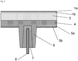
- a T-support profile is accommodated in a U-rib profile, the adhesive filling all 3 sides of the U-rib profile in a uniform thickness in the range of 1-5 mm (cf. Fig. 1 ).
- the adhesive is preferably a two-component polyurethane system with a Shore A 70 hardness.
- the metallic hinge components are connected to the carrier or to a layer connected to the carrier via a two-component polyurethane system with a Shore A 70 hardness.
- plastic composite components Another possible manufacturing process for such plastic composite components is a multi-component injection molding process, in which the support profile is already inserted into the appropriate shape and the plastic and the thermoplastic elastomer, which takes on the adhesive function, are injected.
- the composite component according to the invention has the advantage that very low demands are placed on the geometry of the support profile. Simple reinforcement plates can be inserted, tolerance deviations can be compensated for by the thickness of the adhesive layer.
- the simple geometry means there is no waste of material and the vertical arrangement of the support profile and the main surface of the base body means that less support profile is required. This means on the one hand cost efficiency due to lower material costs and lower manufacturing costs of the support profile, on the other hand weight reduction of the finished part.
- With the help of the adhesive layers occurring loads are evenly and evenly distributed in the plastic, so that there are no stress peaks.
- the new technology also enables components made of amorphous thermoplastics to be stiffened with metal profiles. The type and degree of stiffening and decoupling can be set very flexibly via the rib geometry and the adhesive layer thicknesses. The damping properties of the adhesive layer suppress vibrations and noise.
- Insulation materials can be applied to the inside of the components, optionally also between or above the reinforcing elements, for insulation and noise insulation, preferably in a "direct coating” process. Polyurethane systems are preferably used for this.
- the insulation layer is coated with a further lacquer or surface layer, so that an optically and haptically appealing inner surface of the component is created.
- Vehicle components in the sense of the present invention are tailgates.
- a tailgate based on a carrier (I) made from Makrolon® AG2677 from Bayer MaterialScience AG was produced by injection molding. According to the Figures 1 , 2nd and 3rd realized three different multilayer composites containing the carrier (I). In a preferred embodiment, the tailgate contains the functional elements Fig. 4 .
- Makrolon® AG2677 is a linear, UV-stabilized and easily demoldable polycarbonate based on bisphenol-A. Makrolon® AG2677 has a melt volume flow rate MVR according to ISO 1133 of 12.5 cm 3/10 min, measured at 300 ° C and 1.2 kg load on. The product is available from Bayer MaterialScience AG, Leverkusen.
- Makroblend® 7665 is an elastomer-modified polycarbonate, polyethylene terephthalate blend with 20% mineral filling with a melt volume flow rate MVR according to ISO 1133 of 14 cm 3/10 min, measured at 270 ° C and 5 kg load.
- the product is available from Bayer MaterialScience AG, Leverkusen.
- Makroblend® UT235M is a mineral-filled polyethylene terephthalate easily entformbares polycarbonate blend with a melt volume flow rate MVR according to ISO 1133 of 35 cm 3/10 min, measured at 270 ° C and 5 kg load.
- the product is available from Bayer MaterialScience AG, Leverkusen.
- Bayblend T95MF is a polycarbonate ABS blend with 9% mineral filling and a melt volume-flow rate MVR according to ISO 1133 of 18 cm 3/10 min, measured at 260 ° C and 5 kg load.
- the product is available from Bayer MaterialScience AG, Leverkusen.
- Scratch-resistant paint AS4700 is a thermally curing silicone-based paint containing isopropanol, n-butanol and methanol as a solvent, with a solids content of 25% by weight, a specific density of 0.92 and a viscosity measured at 25 ° C from 3-7.
- the product is available from Momentive Performance Materials GmbH, Leverkusen.
- SHP470 is a primer with a solids content of 7% by weight. a specific density of 0.94 and a viscosity at 25 ° C of 30 to 60 based on 1-methoxy-2-propanol as solvent.
- the product is available from Momentive Performance Materials GmbH, Leverkusen.
- Adhesive is a highly viscous, moisture-curing 1-component polyurethane system (e.g. DOW Betaseal 1842).
- the film 2 can also be dispensed with during manufacture.
- a spoiler (21) is formed in which a transparent area for the third brake light (12) is also integrated. Furthermore, transparent areas for indicators (14) and rear lights (16) are provided, as well as another transparent area underneath the windshield wiper mount (with integrated opening (20). Troughs for logo (18) and license plate (17) are also integrated.
Landscapes
- Engineering & Computer Science (AREA)
- Mechanical Engineering (AREA)
- Injection Moulding Of Plastics Or The Like (AREA)
- Laminated Bodies (AREA)
- Moulds For Moulding Plastics Or The Like (AREA)
Description
- Die Erfindung betrifft ein Verfahren zur Herstellung von fugenlos gefertigten Fahrzeugbauteilen in Form von Heckklappen, mit einem durchgehenden Träger aus einem thermoplastischen Kunststoff, die mindestens einen transparenten Bereich aufweisen, der integraler Bestandteil des Trägers ist.
- Um im Automobilbau das Karosseriegewicht zu reduzieren, werden z.B. Glasscheiben durch transparente Kunststoffscheiben ersetzt. Darüber hinaus werden schon seit langem auch viele außenliegende Fahrzeugbauteile aus Kunststoff gefertigt, wie z.B. Stoßfänger und Schutzkanten.
- Bezüglich der Fahrzeugbauteile besteht ein großes Interesse daran, verschiedene Funktionselemente in die Bauteile zu integrieren, den Bauteilaufbau jedoch so zu gestalten, daß die Bauteile einteilig auf Basis eines einzigen Trägermaterials gefertigt werden können.
- Hierbei müssen insbesondere großflächige Bauteile über eine ausreichende Steifigkeit verfügen, um den an sie gestellten mechanischen Anforderungen gerecht werden zu können. Gleichzeitig sollten die Bauteile jedoch so ausgelegt sein, daß sie ein möglichst niedriges Eigengewicht aufweisen.
- Im Automobilbau bestehen zudem speziell für hochpreisige Fahrzeuge ambitionierte Anforderungen bezüglich des optischen Erscheinungsbildes der verbauten Materialien. Inhomogenitäten, beziehungsweise optische Störungen in der Bauteiloberfläche sind in diesem Zusammenhang nicht akzeptabel.
- Zudem sind aufgrund des immer komplexer werdenden Aufbaus von Fahrzeugbauteilen aktuell vermehrt effiziente Fertigungsverfahren gefragt, die es ermöglichen, die Bauteile in möglichst wenigen Schritten herzustellen.
- Aus
WO 2006/053547 A2 ist eine Klappe für ein Kraftfahrzeug bekannt, die insbesondere als Heckklappe ausgestaltet sein kann. Die Heckklappe kann ein Trägerelement aufweisen, welches einschließlich einer Fensterscheibe einstückig geformt sein kann, beispielsweise aus Polycarbonat. Dabei können diejenigen Bereiche des Trägerelementes, die keine Bestandteile der Fensterscheibe bilden, eingefärbt oder mit einer lichtundurchlässigen Folie überzogen sein. - Es ist somit Aufgabe der vorliegenden Erfindung, fugenlos gefertigte Fahrzeugbauteile mit hoher Steifigkeit und mit geringem Gewicht, aufweisend mindestens einen integrierten transparenten Bereich und ein oder mehrere integrierte Funktionselemente zur Verfügung zu stellen, wobei die gesamte Bauteiloberfläche eine durchgängige, fugenlose ausgezeichnete optische Qualität aufweist.
- Ferner ist es eine Aufgabe der vorliegenden Erfindung ein Verfahren zur Herstellung der erfindungsgemäßen Fahrzeugbauteile bereitzustellen, in dem alle Fertigungsschritte nebst Integration der Funktionselemente in einem Werkzeug realisierbar sind und ein nachträgliches Anbringen und Abdichten der Funktionselemente entfällt.
- Die gestellte Aufgabe konnte überraschenderweise durch ein Fahrzeugbauteil in Form einer Heckklappe gemäß Anspruch 1 und ein Verfahren zu deren Herstellung nach Anspruch 14 gelöst werden.
- Hierbei weist der Träger eine Dicke von 3 - 7 mm, bevorzugt von 4 - 6 mm, besonders bevorzugt von 4,5 - 5,5 mm auf. Die Dicke des Trägers variiert über das gesamte Bauteil maximal um 10%, vorzugsweise maximal um 5%.
- Fugenlos im Sinne der vorliegenden Erfindung bedeutet, daß die äußere Oberfläche des Bauteils keine Fugen oder Übergänge mit einer Tiefe von mehr als 0,20 mm, weiter bevorzugt von mehr als 0,15 mm, und besonders bevorzugt von mehr als 0,10 mm aufweist. Die Fugen oder Übergänge haben weiterhin vorzugsweise eine Breite von nicht mehr als 0,20 mm, weiter bevorzugt von nicht mehr als 0,15 mm, und besonders bevorzugt von nicht mehr als 0,10 mm.
- Der Träger besteht aus einem thermoplastischen Kunststoff, welcher bevorzugt transparent ist, und kann vollkommen eben oder unterschiedlich stark gekrümmt ausgeführt sein. In der ebenen wie in den gekrümmten Ausführungsformen kann der Träger darüber hinaus zusätzlich weiter strukturiert und/oder ausgeformt sein.
- Ferner weist der Träger eine äußere Oberfläche von mindestens 360000 mm2 auf. Bevorzugt weist der Träger eine Oberfläche zwischen 360000 mm2 und 3600000 mm2, weiter bevorzugt zwischen 360000 mm2 und 3300000 mm2, weiter bevorzugt zwischen 810000 mm2 und 3000000 mm2 sowie besonders bevorzugt zwischen 810000 mm2 und 2500000 mm2 auf.
- In einer alternativen Ausführungsform besteht ein Teil des Trägers aus einem transparenten Kunststoff, während ein zweiter Teil aus einem direkt angespritzten nicht-transparenten Kunststoff besteht, wobei die Anspritzübergänge die oben genannten Anforderungen hinsichtlich der Fugen und Übergänge erfüllen. Vorzugsweise bestehen der transparente Teil aus Polycarbonat und der nicht-transparente Teil aus einem Polycarbonatblend, vorzugsweise mit Acrylnitrilbutadien oder Polyester (z.B. PET, PBT). Der Übergang der Materialien liegt vorzugsweise in Kantenbereichen, so daß eventuell auftretende Unebenheiten kaschiert werden.
- Transparent im Sinne der vorliegenden Erfindung bedeutet, daß der Kunststoff eine Lichtransmission (in Anlehnung an ASTM 1003 bzw. ISO 13468; angegeben in % und Lichtart D65/10°) von mindestens 6 %, weiter bevorzugt von mindestens 12 %, und besonders bevorzugt von mindestens 23 % aufweist. Weiterhin ist die Trübung vorzugsweise kleiner als 3 %, weiter bevorzugt kleiner als 2,5 %, und besonders bevorzugt kleiner als 2,0 %.
- Thermoplastische Kunststoffe, die zur Herstellung des Trägers der erfindungsgemäßen Fahrzeugbauteile verwendet werden können, sind Polycarbonat, Copolycarbonat, Polyestercarbonat, Polystyrol, Styrol-Copolymere, aromatische Polyester wie Polyethylenterephthalat (PET), PET-Cyclohexandimethanol-Copolymer (PETG), Polyethylennaphthalat (PEN), Polybutylenterephthalat (PBT), Polyamid, cyclisches Polyolefin, Poly- oder Poly- oder Copolyacrylate und Poly- oder Copolymethacrylat wie z.B. Poly- oder Copolymethylmethacrylate (wie PMMA) sowie Copolymere mit Styrol wie z.B. transparentes Polystyrolacrylnitril (PSAN), thermoplastische Polyurethane, Polymere auf Basis von zyklischen Olefinen (z.B. TOPAS®, ein Handelsprodukt der Firma Ticona) weiter bevorzugt Polycarbonat, Copolycarbonat, Polyestercarbonat, aromatische Polyester oder Polymethylmethacrylat, oder Mischungen der genannten Komponenten, und besonders bevorzugt Polycarbonat und Copolycarbonat.
- Auch Mischungen von mehreren thermoplastischen Polymeren, insbesondere wenn sie transparent miteinander mischbar sind, sind möglich, wobei in einer speziellen Ausführungsform eine Mischung aus Polycarbonat mit PMMA (weiter bevorzugt mit PMMA < 2 Gew.%) oder Polyester bevorzugt ist.
- Eine weitere spezielle Ausführungsform enthält in diesem Zusammenhang eine Mischung aus Polycarbonat und PMMA mit weniger als 2,0 Gew.%, vorzugsweise weniger als 1,0 Gew.%, weiter bevorzugt weniger als 0,5 Gew.%, wobei mindestens 0,01 Gew.% PMMA enthalten sind bezogen auf die Menge Polycarbonat, wobei das PMMA bevorzugt ein Molgewicht <40.000 g/mol aufweist. In einer besonders bevorzugten Ausführungsform beträgt der Anteil an PMMA 0,2 Gew.%, und besonders bevorzugt 0,1 Gew.%, bezogen auf die Menge Polycarbonat, wobei das PMMA bevorzugt ein Molgewicht <40.000 g/mol aufweist.
- Eine alternative weitere spezielle Ausführungsform enthält eine Mischung aus PMMA und Polycarbonat mit weniger als 2 Gew.%, vorzugsweise weniger als 1 Gew.%, weiter bevorzugt weniger als 0,5 Gew.%, wobei mindestens 0,01 Gew.% Polycarbonat enthalten sind bezogen auf die Menge PMMA,
- In einer besonders bevorzugten Ausführungsform beträgt der Anteil an Polycarbonat 0,2 Gew.%, und besonders bevorzugt 0,1 Gew.%, bezogen auf die Menge PMMA.
- Geeignete Polycarbonate für die Herstellung der erfindungsgemäßen Kunststoffzusammensetzung sind alle bekannten Polycarbonate. Dies sind Homopolycarbonate, Copolycarbonate und thermoplastische Polyestercarbonate.
- Die Herstellung der Polycarbonate erfolgt vorzugsweise nach dem Phasengrenzflächenverfahren oder dem Schmelze-Umesterungsverfahren, welche mannigfaltig in der Literatur beschrieben werden.
- Zum Phasengrenzflächenverfahren sei beispielhaft auf H. Schnell, "Chemistry and Physics of Polycarbonates", Polymer Reviews, Vol. 9, Interscience Publishers, New York 1964 S. 33 ff., auf Polymer Reviews, Vol. 10, "Condensation Polymers by Interfacial and Solution Methods", Paul W. Morgan, Interscience Publishers, New York 1965, Kap. VIII, S. 325, auf Dres. U. Grigo, K. Kircher und P. R- Müller "Polycarbonate" in Becker/Braun, Kunststoff-Handbuch, Band 3/1, Polycarbonate, Polyacetale, Polyester, Celluloseester, Carl Hanser Verlag München, Wien 1992, S. 118-145 sowie auf
EP 0 517 044 A1 verwiesen. - Das Schmelze-Umesterungsverfahren ist beispielsweise in der Encyclopedia of Polymer Science, Vol. 10 (1969), Chemistry and Physics of Polycarbonates, Polymer Reviews, H. Schnell, Vol. 9, John Wiley and Sons, Inc. (1964) sowie in den Patentschriften
DE-B 10 31 512 undUS-B 6 228 973 beschrieben. - Die Polycarbonate werden bevorzugt durch Reaktionen von Bisphenolverbindungen mit Kohlensäureverbindungen, insbesondere Phosgen oder beim Schmelzeumesterungsprozess Diphenylcarbonat bzw. Dimethylcarbonat, dargestellt.
- Hierbei sind Homopolycarbonate auf Basis Bisphenol-A und Copolycarbonate auf der Basis der Monomere Bisphenol-A und 1,1-Bis-(4-hydroxyphenyl)-3,3,5-trimethylcyclohexan besonders bevorzugt.
- Diese und weitere Bisphenol- bzw. Diolverbindungen, die sich für die Polycarbonatsynthese einsetzen lassen, sind unter anderem offenbart in
WO 2008037364 A1 (s.7, Z. 21 bis s. 10, Z. 5),EP 1 582 549 A1 ([0018] bis [0034]),WO 2002026862 A1 (S. 2, Z. 20 bis S. 5, Z. 14),WO 2005113639 A1 (S. 2, Z.1 bis S. 7, Z. 20). - Die Polycarbonate können linear oder verzweigt sein. Es könne auch Mischungen aus verzweigten und unverzweigten Polycarbonaten eingesetzt werden.
- Geeignete Verzweiger für Polycarbonate sind aus der Literatur bekannt und beispielsweise beschrieben in den Patentschriften
US-B 4 185 009 undDE 25 00 092 A1 (erfindungsgemäße 3,3-bis-(4-hydroxyaryl-oxindole, s. jeweils gesamtes Dokument),DE 42 40 313 A1 (s. S. 3, Z. 33 bis 55),DE 19 943 642 A1 (s. S. 5, Z. 25 bis 34) undUS-B 5 367 044 sowie in hierin zitierter Literatur. - Darüber hinaus können die verwendeten Polycarbonate auch intrinsisch verzweigt sein, wobei hier kein Verzweiger im Rahmen der Polycarbonatherstellung zugegeben wird. Ein Beispiel für intrinsische Verzweigungen sind so genannte Fries-Strukturen, wie sie für Schmelzepolycarbonate in der
EP 1 506 249 A1 offenbart sind. - Zudem können bei der Polycarbonat-Herstellung Kettenabbrecher eingesetzt werden. Als Kettenabbrecher werden bevorzugt Phenole wie Phenol, Alkylphenole wie Kresol und 4-tert.-Butylphenol, Chlorphenol, Bromphenol, Cumylphenol oder deren Mischungen verwendet.
- Die Polycarbonate können darüber hinaus übliche Polymeradditive, wie z.B. die in
EP-A 0 839 623 ,WO-A 96/15102 EP-A 0 500 496 oder "Plastics Additives Handbook", Hans Zweifel, 5th Edition 2000, Hanser Verlag, München beschriebenen Flammschutzmittel, optische Aufheller, Fließverbesserer, organische oder anorganische Farbmittel, Thermostabilisatoren, anorganische Pigmente, Entformungsmittel oder Verarbeitungshilfsmittel enthalten. - Ferner können. UV-Absorber oder IR-Absorber enthalten sein. Geeignete UV-Absorber sind beispielsweise beschrieben in der
EP 1 308 084 A1 , in derDE 102007011069 A1 sowie in derDE 10311063 A1 . - Geeignete IR-Absorber sind beispielsweise in
EP 1 559 743 A1 ,EP 1 865 027 A1 ,DE 10022037 A1 ,DE 10006208 A1 sowie in den italienischen PatentanmeldungenRM2010A000225 RM2010A000227 RM2010A000228 - Von den in der zitierten Literatur genannten IR-Absorbern sind solche auf Borid- und Wolframatbasis sowie auf ITO und ATO basierende Absorber sowie Kombinationen daraus bevorzugt.
- In einer besonders bevorzugten Ausführungsform der vorliegenden Erfindung ist der thermoplastische Kunststoff für den Träger des Fahrzeugbauteils ein Polycarbonat mit einem Molekulargewicht Mw von 22.000 bis 30.000, weiter bevorzugt von 24.000 bis 28.000 und besonders bevorzugt von 25.000 bis 27.000, ermittelt durch Gelpermeationschromatographie mit Polycarbonateichung.
- Die Fließfähigkeit des für die Herstellung des Trägers verwendeten Polycarbonats reicht ferner aus, um im Spritzprägeprozeß Fließwege von 600 mm bis 1200 mm, bevorzugt 800 mm bis 1100 mm, besonders bevorzugt 900 mm bis 1000 mm zu realisieren, wobei die Schmelzetemperatur vorzugsweise von 280 °C bis 320 °C, weiter bevorzugt von 300 °C bis 310 °C beträgt, die Werkzeugtemperatur vorzugsweise von 60 °C bis 110 °C, weiter bevorzugt von 80 °C bis 100 °C beträgt, der Fülldruck von 50 bar bis 1000 bar, weiter bevorzugt von 80 bar bis 750 bar und besonders bevorzugt von 100 bar bis 500 bar liegt, und der Prägespalt von 0,5 mm bis 10 mm, vorzugsweise von 2 mm bis 7mm, besonders bevorzugt von 5 mm bis 6 mm ist.
- Die erfindungsgemäßen Fahrzeugbauteile enthaltend den Träger aus thermoplastischem Kunststoff, nachfolgend auch als Basisschicht (I) des erfindungsgemäßen Fahrzeugbauteils bezeichnet, können zudem im Sinne eines mehrlagigen Verbundes weitere Schichten enthalten.
- Hierbei bilden der Träger, alle mit diesem mittelbar oder unmittelbar verbundenen Schichten sowie die integrierten Funktionselemente das erfindungsgemäße Fahrzeugbauteil.
- Folgende Funktionselemente können hierbei in dem erfindungsgemäße Fahrzeugbauteil integral ausgeformte und/oder eingebunden sein:
- Scharniere
- Heizelemente
- Antennen
- Schließfunktionalitäten
- Lampengehäuse /-aufnahme z.B. für Rücklichter, Blinker, Bremslichter, Kennzeichenbeleuchtung und hochgesetzte Bremsleuchte
- Scheibenwischer(und -motor)aufnahme
- Kennzeichenmulde
- Spoiler
- Stylinglinien
- Strukturelemente für das Wassermanagement (Ableiten von Spritz- und Regenwasser)
- Nummernschildaufnahme außen oder innen
- Solarmodule
- Auf dem Träger können zusätzlich zu Schichten zur Ausbildung von Schwarzrändern und/ oder verstärkenden Rahmenelementen, welche aus den vorgenanten thermoplastischen Kunststoffen oder deren Mischungen hergestellt sein können und bevorzugt nicht transparent sind, zudem eine oder mehrere der folgenden Schichten in unterschiedlichen
- Abfolgen entweder auf einer Seite des Trägers oder auf beiden Seiten des Trägers aufgebracht werden. Hierzu zählen:
- (II) Schichten zur Erhöhung der Kratzfestigkeit insbesondere über dem transparenten Sichtbereich des Fahrzeugbauteils.
- (III) Schichten zum Schutz vor Witterungseinflüssen beispielsweise enthaltend UV-Absorber und/oder IR-Absorber, wobei hierzu auch Reflexionsschichten für IR- und UV-Strahlung zählen (IR-Strahlung von 750 nm - 2500 nm, UV-Strahlung von 400 nm bis 180 nm) .
- (IV) Farbgebende Schichten enthaltend Farbmittel und oder Pigmente
- (VI) mechanische Verstärkungselemente,
- (VII) Funktionsschichten wie Antibeschlag-, Antireflexschichten sowie Schichten zur Transparenzsteuerung (Elektrochromie, Thermotropie, Thermochromie)
- (VIII) Dämm- und Isolierschichten
- Es sind verschiedene Methoden bekannt, um eine Kratzfestbeschichtung im Sinne der vorliegenden Erfindung herzustellen. Beispielsweise können Epoxy-, Acryl-, Polysiloxan-, kolloidales Kieselgel-, oder anorganisch/organisch (Hybridsysteme) basierte Lacke verwendet werden. Diese Systeme können über beispielsweise über Tauchverfahren, Spincoating, Sprühverfahren, oder Flutbeschichtung aufgebracht werden. Die Aushärtung kann thermisch oder mittels UV-Bestrahlung erfolgen. In einer speziellen Ausführungsform wird Kratzfestschicht in einem Inline-Verfahren (Direct Coating / Direct Skinning) direkt auf den Träger aufgebracht.
- Es können Ein- oder Mehrschichtsysteme verwendet werden. Die Kratzfestbeschichtung kann z.B. direkt oder nach Vorbereitung der Substratoberfläche mit einer Grundierung (Primer) aufgetragen werden. Ferner kann eine Kratzfestbeschichtung über Plasma-gestützte Polymerisationsverfahren aufgebracht werden, z.B. über ein SiO2-Plasma.
- Weiterhin ist es möglich, über bestimmte Spritzgussverfahren, wie z.B. das Hinterspritzen von oberflächenbehandelten Folien, eine Kratzfestbeschichtung auf den resultierenden Formkörper aufzubringen.
- In der Kratzfestschicht können verschiedene Additive, wie z.B. UV-Absorber, abgeleitet z.B. von Triazolen oder Triazinen, vorhanden sein. Ferner können IR-Absorber organischer oder anorganischer Natur enthalten sein. Diese Additive können im Kratzfestlack selbst oder in der Primerschicht enthalten sein. Die Dicke der Kratzfestschicht beträgt 1 - 20 µm, bevorzugt 2 - 15 µm. Unterhalb von 1 µm ist die Beständigkeit der Kratzfestschicht ungenügend. Oberhalb von 20 µm treten häufiger Risse im Lack auf. Das erfindungsgemäße Basismaterial, welches in der vorliegenden Erfindung beschrieben wird, wird bevorzugt nach Fertigstellung des Spritzgussartikels mit einer oben beschriebenen Kratzfest- und/oder Antireflexschicht versehen, da der bevorzugte Einsatzbereich im Bereich von Fenster- oder- Automobilverscheibung liegt.
- Für Polycarbonate wird bevorzugt ein UV-Absorber enthaltener Primer eingesetzt, um die Haftung des Kratzfestlackes zu verbessern. Der Primer kann weitere Stabilisatoren wie z.B. HALS-Systeme (Stabilisatoren auf Basis sterisch gehinderter Amine), Haftvermittler, Fließhilfsmittel enthalten.
- Das jeweilige Harz kann aus einer Vielzahl von Materialien ausgewählt werden und ist z.B. in Ullmann's Encylopedia of Industrial Chemistry, 5th Edition, Vol. A18, pp. 368-426, VCH, Weinheim 1991 beschrieben. Es können Polyacrylate, Polyurethane, Phenol-basierte, Melaminbasierte, Epoxy- und Alkyd-Systeme oder Mischungen dieser Systeme eingesetzt werden. Das Harz wird meist in geeigneten Lösemitteln gelöst - häufig in Alkoholen.
- Abhängig vom gewählten Harz kann die Aushärtung bei Raumtemperatur oder bei erhöhten Temperaturen erfolgen. Bevorzugt werden Temperaturen zwischen 50 °C und 130 °C eingesetzt - häufig nach dem ein Großteil des Lösemittels kurzzeitig bei Raumtemperatur entfernt wurde. Kommerziell erhältliche Systeme sind z.B. SHP470, SHP470FT-2050 und SHP401 der Firma Momentive Performance Materials. Derartige Beschichtungen sind z.B. in
US 6350512 B1 ,US 5869185 ,WO 2006/108520 sowieEP 1308084 beschrieben. - Kratzfest-Lacke (Hard-Coat) sind bevorzugt aus Siloxanen aufgebaut und enthalten bevorzugt UV-.Absorber. Sie werden bevorzugt über Tauch- oder Fließverfahren aufgebracht. Die Aushärtung erfolgt bei Temperaturen von 50 °C - 130 °C. Kommerziell erhältliche Systeme sind z.B. AS4000, SHC5020 und AS4700 von Momentive Performance Materials. Derartige Systeme sind z.B. in
US 5041313 ,DE 3121385 ,US 5391795 ,WO 2008/109072 beschrieben. Die Synthese dieser Materialien erfolgt meist über Kondensation von Alkoxy- und/oder Alkylalkoxysilanen unter Säure- oder Basenkatalyse. Optional können Nanopartikel eingearbeitet werden. Bevorzugte Lösemittel sind Alkohole wie Butanol, Isopropanol, Methanol, Ethanol und deren Mischungen. - Anstatt von Primer / Kratzfestbeschichtungs-Kombinationen können Einkomponenten-Hybrid-Systeme eingesetzt werden. Diese sind z.B. in
EP 0570165 oderWO 2008/071363 oderDE 2804283 beschrieben. Kommerziell erhältlich Hybrid-Systeme sind z.B. unter den Namen PHC587 oder UVHC 3000 von Momentive Performance Materials erhältlich. - In einem besonders bevorzugtem Verfahren erfolgt die Applikation des Lackes über das Flutverfahren, da es zu beschichteten Teilen mit hoher optischer Qualität führt.
- Das Flutverfahren kann manuell mit Schlauch oder geeignetem Beschichtungskopf oder automatisch im Durchlauf über Flutlackierroboter- und gegebenenfalls Schlitzdüsen erfolgen.
- Hierbei könne die Bauteile, sowohl hängend als auch in einem entsprechenden Warenträger gelagert, beschichtet werden.
- Bei größeren und/oder 3D-Bauteilen wird das zu beschichtende Teil in einen geeigneten Warenträger eingehangen oder aufgesetzt.
- Bei Kleinteilen kann die Beschichtung auch per Hand durchgeführt werden. Hierbei wird die zuschichtende flüssige Primer- oder Lacklösung ausgehend von der oberen Kante des Kleinteiles in Längsrichtung über die Platte gegossen, während gleichzeitig der Ansatzpunkt des Lackes auf der Platte von links nach rechts über die Plattenbreite geführt wird. Die lackierten Platten werden senkrecht an einer Klammer hängend nach den jeweiligen Herstellervorgaben abgelüftet und gehärtet.
- Die Schichten (III) basieren vorzugsweise auf thermoplastischen Kunststoffen, wobei hierbei vorzugsweise die thermoplastischen Kunststoffe, welche auch für die Herstellung des Trägers (I) verwendet werden, zum Einsatz kommen. Polycarbonate und Poly- oder Copolymethacrylate wie z.B. Poly- oder Copolymethylmethacrylate (wie PMMA) sind hierbei besonders bevorzugt. Die zur Herstellung von (III) verwendeten thermoplastischen Kunststoffe werden derart additiviert, daß deren Beständigkeit gegenüber Strahlung insbesondere im Bereich von 180 nm bis 400 nm und/oder im Bereich von 750 nm bis 2500 nm signifikant erhöht wird.
- Hierzu werden UV-Absorber (siehe beispielsweise
EP 1 308 084 A1 ,DE 102007011069 A1 oderDE 10311063 A1 ) und /oder IR Absorber (siehe beispielsweiseEP 1 559 743 A1 ,EP 1 865 027 A1 ,DE 10022037 A1 ,DE 10006208 A1 sowie die italienischen PatentanmeldungenRM2010A000225 RM2010A000227 RM2010A000228 - Ferner können weitere übliche Polymeradditive, wie z.B. die in
EP-A 0 839 623 ,WO-A 96/15102 EP-A 0 500 496 oder "Plastics Additives Handbook", Hans Zweifel, 5th Edition 2000, Hanser Verlag, München beschriebenen, optische Aufheller, Fließverbesserer, Thermostabilisatoren, Entformungsmittel oder Verarbeitungshilfsmittel enthalten sein. - Die Schichten zum Schutz vor Witterungseinflüssen (III) können nach Verfahren hergestellt werden, wie sie für die Fertigung von Mehrschichtsystemen aus einer Basis- und optionaler Deckschicht / optionalen Deckschichten üblich sind. Zu diesen Verfahren zählen die (Co)extrusion, Direct Skinning, Direct Coating, Insert Moulding, Folienhinterspritzen, oder sonstige dem Fachmann bekannte geeignete Verfahren.
- Spritzgießverfahren sind dem Fachmann bekannt und beispielsweise im "Handbuch Spritzgiessen", Friedrich Johannnaber/Walter Michaeli, München; Wien: Hanser, 2001, ISBN 3-446-15632-1 oder "Anleitung zum Bau von Spritzgiesswerkzeugen", Menges/Michaeli/Mohren, München; Wien: Hanser, 1999, ISBN 3-446-21258-2 beschrieben.
- Extrusionsverfahren sind dem Fachmann bekannt und beispielsweise für die Coextrusion unter anderem beschrieben in
EP-A 0 110 221 ,EP-A 0 110 238 undEP-A 0 716 919 . Für Details des Adapter- und Düsenverfahrens siehe Johannaber/Ast:"Kunststoff- Maschinenführer", Hanser Verlag, 2000 und in Gesellschaft Kunststofftechnik: "Coextrudierte Folien und Platten: Zukunftsperspektiven, Anforderungen, Anlagen und Herstellung, Qualitätssicherung", VDI-Verlag, 1990. - Für die Herstellung von erfindungsgemäß vorgesehenen Schwarzrändern beziehungsweise verstärkenden Rahmenelementen (V) bietet sich als Material die Verwendung thermoplastischer Kunststoffe enthaltend Füll- beziehungsweise Verstärkungsstoffe, insbesondere die Verwendung von derart ausgerüsteten Kunststoff Blends an. In diesem Zusammenhang sind Blends enthaltend Polycarbonat und mindestens einen weiteren thermoplastischen Kunststoff bevorzugt.
- Die verwendeten Füll- und Verstärkungsstoffe können faser-, plättchen-, röhren-, stäbchen- oder kugelförmig bzw. sphärisch oder partikulär sein. Zu den im Sinne der vorliegenden Erfindung geeigneten Füll- und Verstärkungsstoffen zählen beispielsweise Talk, Wollastonit, Glimmer, Kaolin, Kieselgur, Calciumsulfat, Calciumcarbonat, Bariumsulfat, Glasfasern, Glas- oder Keramikkugeln, Glashohlkugeln oder Keramikhohlkugeln, Glas- oder Mineralwolle, Kohlefasern oder Carbon-Nanotubes. Bevorzugte Füllstoffe sind Füllstoffe, die ein isotropes Schwindungsverhalten der Zusammensetzung bewirken.
- Im Rahmen der vorliegenden Erfindung ist die Verwendung von Talk und Kurzglasfasern besonders bevorzugt.
- Glas- oder Keramikkugeln oder -hohlkugeln können dabei die Kratzfestigkeit dieser Oberfläche erhöhen.
- In den Zusammensetzungen (V) ist der Gehalt an Füll- und Verstärkungsstoffen von 5 Gew.% bis 40 Gew.%, vorzugsweise von 7 Gew.% bis 30 Gew.%, weiter bevorzugt von 8 Gew.% bis 25 Gew.%., wobei sich die Gewichtsangaben auf die Gesamtzusammensetzung von (V) beziehen.
- Ferner kann das für die Herstellung von (V) verwendete Material optional die in
EP-A 0 839 623 ,WO-A 96/15102 EP-A 0 500 496 oder "Plastics Additives Handbook", Hans Zweifel, 5th Edition 2000, Hanser Verlag, München beschriebenen üblichen Polymeradditive enthalten. - Hierzu zählen unter anderem organische und/oder organische Farbmittel oder Pigmente, UV-Absorber, IR-Absorber, Entformungsmittel, Thermostabilisatoren oder Verarbeitungsstabilisatoren.
- In einer speziellen Ausführungsform der vorliegenden Erfindung handelt es sich bei dem Kunststoff Blend um ein Blend enthaltend mindestens ein Polycarbonat um mindestens einen Polyester, wobei der Polyester bevorzugt ein Polyalkylenterephthalat, weiter bevorzugt ein Polyethylenterephthalat (PET) oder ein Polybutylenterephthalat (PBT) ist. Als Polyester besonders bevorzugt ist PET.
- Der Mengenanteil von Polycarbonat in den Polycarbonat Polyester Blends beläuft sich auf 10 Gew.-% bis 90 Gew.-%, bevorzugt 30 Gew.-% bis 80 Gew.-%, weiter bevorzugt 35 Gew.-% bis 70 Gew.-%, besonders bevorzugt 40 Gew.-% bis 65 Gew.-% jeweils bezogen auf die Gesamtzusammensetzung von (V).
- Der Mengenanteil des Polyesters in den Polycarbonat Polyester Blends beläuft sich auf 60 Gew.-% bis 5 Gew.-%, bevorzugt 50 Gew.-% bis 10 Gew.-%, weiter bevorzugt 35 Gew.-% bis 10 Gew.-%, besonders bevorzugt 25 Gew.-% bis 15 Gew.-% jeweils bezogen auf die Gesamtzusammensetzung von (V).
- Optional können die Zusammensetzungen von (V) auch Elastomermodifikatoren enthalten die in Mengen von 0 Gew.-% bis 25 Gew.-%, bevorzugt 3 Gew.-% bis 20 Gew.-%, weiter bevorzugt 6 Gew.-% 20 Gew.-% und besonders bevorzugt 8 Gew.-% bis 18 Gew.-% enthalten sein können. Auch hier beziehen sich die Gew.-% Angaben auf die Gesamtzusammensetzung von (V)
- In einer alternativen speziellen Ausführungsform der vorliegenden Erfindung handelt es sich bei dem bei dem Kunststoff Blend um eine Zusammensetzung umfassend die Kunststoffe A) und B), wobei
- A) 10 bis 100 Gew.-Teile, bevorzugt 60 bis 95 Gew.-Teile, besonders bevorzugt 75 bis 95 Gew.-Teile, insbesondere 85 bis 95 Gew.-Teile (bezogen auf die Summe der Komponenten A) und B) mindestens einer Komponente ausgewählt aus der Gruppe bestehend aus aromatischem Polycarbonat, aromatischem Polyestercarbonat, Polymethylmethacrylat-(Co)Polymer und Polystyrol-(Co)Polymer, ist und
- B) 0 bis 90 Gew.-Teile, bevorzugt 5 bis 40 Gew.-Teile, besonders bevorzugt 5 bis 25 Gew.-Teile, insbesondere 5 bis 15 Gew.-Teile (bezogen auf die Summe der Komponenten A)und B) mindestens eines Propfpolymerisats. Das Propfpolymerisat ist bevorzugt hergestellt im Emulsionspolymerisationsverfahren, Suspensionsverfahren, Massepolymerisationsverfahren, oder Lösungsverfahren.
- C) optional kautschukfreies Vinylhomopolymerisat und/oder kautschukfreies Vinylcopolymerisat
- Die Komponente B umfasst vorzugsweise ein oder mehrere Pfropfpolymerisate von
- B.1.1 5 bis 95, vorzugsweise 30 bis 90 Gew.-%, wenigstens eines Vinylmonomeren auf
- B.1.2 95 bis 5, vorzugsweise 70 bis 10 Gew.-% einer oder mehrerer Pfropfgrundlagen.
- Die Glasübergangstemperaturen der Propfgrundlagen sind vorzugsweise < 10°C, vorzugsweise < 0°C, besonders bevorzugt < -20°C.
- Die Pfropfgrundlage B.1.2 hat im allgemeinen eine mittlere Teilchengröße (d50-Wert) von 0,05 bis 10 µm, vorzugsweise 0,1 bis 5 µm, besonders bevorzugt 0,15 bis 1 µm.
- Monomere B.1.1 sind vorzugsweise Gemische aus
- B.1.1.1 50 bis 99 Gew.-Teilen Vinylaromaten und/oder kernsubstituierten Vinylaromaten (wie Styrol, α-Methylstyrol, p-Methylstyrol, p-Chlorstyrol) und/oder Methacrylsäure-(C1-C8)-Alkylester, wie Methylmethacrylat, Ethylmethacrylat), und
- B.1.1.2 1 bis 50 Gew.-Teilen Vinylcyanide (ungesättigte Nitrile wie Acrylnitril und Methacrylnitril) und/oder (Meth)Acrylsäure-(C1-C8)-Alkylester, wie Methylmethacrylat, n-Butylacrylat, t-Butylacrylat, und/oder Derivate (wie Anhydride und Imide) ungesättigter Carbonsäuren, beispielsweise Maleinsäureanhydrid und N-Phenyl-Maleinimid.
- Bevorzugte Monomere B.1.1.1 sind ausgewählt aus mindestens einem der Monomere Styrol, α-Methylstyrol und Methylmethacrylat, bevorzugte Monomere B.1.1.2 sind ausgewählt aus mindestens einem der Monomere Acrylnitril, Maleinsäureanhydrid und Methylmethacrylat. Besonders bevorzugte Monomere sind B.1.1.1 Styrol und B.1.1.2 Acrylnitril.
- Für die Pfropfpolymerisate B.1 geeignete Pfropfgrundlagen B.1.2 sind beispielsweise Dienkautschuke, EP(D)M-Kautschuke, also solche auf Basis Ethylen/Propylen und gegebenenfalls Dien, Acrylat-, Polyurethan-, Silikon-, Chloropren- und Ethylen/Vinylacetat-Kautschuke sowie Silikon/Acrylat-Kompositkautschuke.
- Bevorzugte Pfropfgrundlagen B.1.2 sind Dienkautschuke, beispielsweise auf Basis Butadien und Isopren, oder Gemische von Dienkautschuken oder Copolymerisate von Dienkautschuken oder deren Gemischen mit weiteren copolymerisierbaren Monomeren (z.B. gemäß B.1.1.1 und B.1.1.2), mit der Maßgabe, dass die Glasübergangstemperatur der Komponente B.2 unterhalb < 10°C, vorzugsweise < 0°C, besonders bevorzugt < -20°C liegt. Besonders bevorzugt ist reiner Polybutadienkautschuk.
- Besonders bevorzugte Polymerisate B.1 sind beispielsweise ABS-Polymerisate (Emulsions-, Masse- und Suspensions-ABS), wie sie z.B. in der
DE-OS 2 035 390 3 644 574 ) oder in derDE-OS 2 248 242 1 409 275 - Die Glasübergangstemperaturen wird mittels dynamischer Differenz-Thermoanalyse (DSC) gemäß der Norm DIN EN 61006 bei einer Heizrate von 10 K/min mit Definition der Tg als Mittelpunkttemperatur (Tangentenmethode) bestimmt.
- Bevorzugt ist ist A) Polycarbonat und B) Acrylnitrilbutadienstyrol (ABS).
- Zum Vermeiden von Bauteilspannungen ist darauf zu achten, daß die thermischen Ausdehnungskoeffizienten der einzelnen Schichten durch eine geeignete Materialauswahl aufeinander abgestimmt sind.
- Dies ist insbesondere dann wichtig, da auf den Träger des erfindungsgemäßen Fahrzeugbauteils ein Schwarzrand beziehungsweise Rahmenelement unmittelbar aufgebracht wird.
- Hierbei hat es sich als vorteilhaft herausgestellt, für den Schwarzrand beziehungsweise das Rahmenelement ein Material zu wählen, dessen linearer thermischer Ausdehnungskoeffizient in Längsrichtung (d.h. vom Anguß betrachtet in Richtung des Schmelzflusses, nachfolgend als RS abgekürzt) niedriger ist, als der des Materials des Trägers. Zudem sollte das RS/QS-Verhältnis des linearen thermischen Ausdehnungskoeffizienten des jeweiligen Material in einem relativ engen Bereich liegen, wobei QS die Querrichtung, d. h. die Richtung orthogonal zur vom Anguß betrachteten Richtung des Schmelzflusses meint.
- In einer Ausführungsform der vorliegenden Erfindung ist der lineare thermische Ausdehnungskoeffizient des Rahmenmaterials in Längsrichtung um 1x10⁻⁵ bis 3x10⁻⁵ (mm/mm K) niedriger als der des Trägermaterials.
- Der Quotient RS/RQ sollte in einem Bereich von 0,6 bis 1,0 liegen.
- Das Material zur Ausbildung des Schwarzrandes beziehungsweise des verstärkenden Rahmenelements wird bevorzugt durch partielles Hinterspritzen des Trägers mit diesem verbunden.
- Da der Träger bevorzugt aus einem transparenten thermoplastischen Kunststoff besteht, kann durch das Hinterspritzen des Schwarzrandes beziehungsweise des verstärkenden Rahmenelements ein Sichtbereich im Sinne einer Fensterscheibe dargestellt werden. Bezogen auf das gesamte erfindungsgemäße Fahrzeugbauteil beträgt der transparente Sichtbereich in Summe 10 - 90 %, weiter bevorzugt 20-75 % und besonders bevorzugt 30 - 50 % der Bauteilfläche und kann durchgängig oder in Form von transparenten Teilflächen, welche durch nicht transparentes hinterspritztes Material optisch voneinander getrennt sind, ausgeführt sein.
- Auf diese Weise können transparente Oberflächen geschaffen werden, hinter denen Leuchten oder Kennzeichen angeordnet werden.
- Der große Vorteil dieser Ausführungsform ist es, daß eine Scheibe nicht mehr, wie in bislang gängigen Serienkonzepten üblich, eingeklebt und abgedichtet werden muß, was den Aufwand bei Montage und Logistik vereinfacht.
- Bei Motorhauben, Frontklappen und Heckklappen reduziert sich die Zahl der Bauteile für die Beleuchtungselemente mindestens um die Komponenten, die in der bisherigen Bauweise außen angebracht waren. Auch das Abdichten der Leuchten ist nicht mehr notwendig, ebenso konnte die Mulde für das Logo in das Bauteil integriert werden,
- Die Transparenz des Trägermaterials ermöglicht zudem, das Fahrzeugkennzeichen hinter die den Träger zu verlegen, z.B. zum Diebstahlschutz. Anstelle separat montierter Schlösser und Öffnungsgriffe können außerdem Lichtsensoren hinter der Polycarbonat-Außenhaut installiert werden, mit denen sich die Klappe oder Tür öffnen und schließen lässt.
- Die Verstärkungselemente (VI) verleihen dem erfindungsgemäßen Fahrzeugbauteil eine hohe Steifigkeit bei gleichzeitig niedrigem Gewicht und weisen im Rahmen der vorliegenden Erfindung bevorzugt einen Grundkörper, eine Rippenstruktur sowie ein Stützprofil auf und werden vorzugsweise im Spritzgussverfahren oder Extrusionsverfahren hergestellt und können aus demselben Material oder verschiedenen Materialien bestehen. Hierbei kann bevorzugt auch der Träger (I) oder eine mit ihm mittelbar oder unmittelbar verbundene Schicht selbst den Grundkörper für das Verstärkungselement bilden.
- Die Verstärkungselemente (VI) können sich hierbei vollständig über die Fläche einer Seite des Trägers ausgenommen die transparenten Sichtbereiche erstrecken. Aber auch die Positionierung von (VI) auf Teilflächen des Trägers außerhalb des Sichtbereichs ist möglich. Hierzu zählen insbesondere Bereiche mit besonders hoher mechanischer Beanspruchung. Bei beweglichen Automobilteilen können dies beispielsweise die Bereiche sein, in denen Scharniere oder bewegliche Funktionsteile wie Scheibenwischer integriert sind.
- Als Materialien für die Rippenstruktur kommen thermoplastische Kunststoffe infrage. Es eignet sich insbesondere ein unverstärkter, verstärkter und/oder gefüllter Kunststoff auf Basis von Polyamid (PA), Polyester, insbesondere Polyethylenterephthalat (PET), Polybutylenterephthalat (PBT), Polyacrylate, insbesondere Polymethylmethacrylat (PMMA), Polybutylenterephthalat (PBT), Polystyrol (PS), syndiotaktisches Polystyrol, Acrylnitril-Butadien-Styrol (ABS), Polyolefin, insbesondere Polypropylen (PP), Polyethylen (PE), Polycarbonat (PC), Copolycarbonat (CoPC), Copolyestercarbonat oder eine Mischung dieser Kunststoffe.
- In einer bevorzugten Ausführungsform handelt es sich bei den Kunststoffen um amorphe thermoplastische Kunststoffe, insbesondere um Polycarbonat, Copolycarbonat, Copolyestercarbonat, PC-Blends und Polymethylmethacrylat.
- Das in die Rippenstruktur eingelegte Stützprofil kann einteilig oder mehrteilig sein. Es kann entweder massiv oder mit Hohlräumen, Kanälen oder dergleichen, gefertigt sein. In einfachster und einer bevorzugten Ausführung ist das Stützprofil ein I-Profil, ein L-Profil oder ein T-Profil. Möglich ist auch ein U-Profil, welches z.B. auch Rippenpaare verbindet. Es kann ein geschlossenes Profil sein, z.B. ein Rechteckrohr. In diesem Fall können die Geometrien der schmalen und breiten Seitenflächen identisch sein. Bei einer entsprechenden Geometrie kann das Stützprofil z.B. einen oder mehrere Kanäle enthalten, die zur Aufnahme von Kabeln und Schläuchen oder zur Leitung von Flüssigkeiten genutzt werden können. Das Stützprofil kann in der Geometrie seiner Flächen den Rippen entsprechen, so dass das eingelegte Profil die gleiche Höhe wie die Rippen besitzt, es kann jedoch auch niedriger oder höher als die Rippen sein, so dass es gegebenenfalls über die Rippe bzw. aus dem Rippenpaket herausragt. Die Geometrie des Stützprofils kann so ausgeführt sein, dass es weitere Funktionen z.B. als Befestigungselement übernehmen kann. In diesem Fall handelt es sich bei dem Stützprofil bereits um ein Halbzeug mit über die einfache Verstärkungsfunktion hinausgehenden Eigenschaften. Das Stützprofil kann ebenfalls so ausgeführt sein, dass eine kraft- und/oder formschlüssige Verbindung zu mindestens einem weiteren Bauteil über die Struktur des Stützprofils läuft.
- Erfindungsgemäß wird mindestens eine breite Seitenfläche des Stützprofils mit einer Rippe verklebt und eine schmale Seitenfläche des Profils steht auf dem Kunststoffgrundkörper. Breite Seitenfläche des Profils und die Fläche des Kunststoffgrundkörpers stehen somit senkrecht oder annähernd senkrecht (in einem Winkel von ca. 70 - 110°) zueinander.
- Das Stützprofil kann aus metallischen, Faserverbund- oder keramischen Werkstoffen sein. Es kann durch Strangpressen, Stanzen, Tiefziehen, Rollformen oder sonstigen formgebende Prozesse hergestellt werden.
- Bevorzugt wird das Stützprofil aus einem metallischen Werkstoff hergestellt. In einer besonders bevorzugten Ausführungsform handelt es sich bei dem Stützprofil um ein einfaches Verstärkungsprofil aus einem Blech vorzugsweise aus Stahl, Eisen, Titan, Aluminium oder Magnesium oder Legierungen dieser Metalle. In einer besonders bevorzugten Ausführungsform ist das Stützprofil ein gewalzter Bandstahl oder ein Aluminiumstrangpressprofil.
- In anderen Ausführungsformen können die Profile auch aus Keramik, Duromeren oder Kunststoff-Komposit-Werkstoffen bestehen.
- Bei dem zur Verklebung verwendeten Strukturklebstoff kann es sich um handelsüblichen Klebstoff handeln, wie er beispielsweise in der Automobilindustrie zur Verklebung von Scheiben oder Blechstrukturen genutzt wird. Es können sowohl Nassklebstoffe, Kontaktklebstoffe, Schmelzklebstoffe oder Reaktionsklebstoffe eingesetzt werden. Besonders geeignet für diese Technologie sind ein- oder zweikomponentige Strukturklebstoffe auf Polyurethanbasis mit unterschiedlichen Steifigkeiten. Es können jedoch auch z.B. Klebstoffe auf Acryl/Acrylat-, Methylmethacrylat-, Silikon oder Epoxidharzbasis verwendet werden. Im Rippenpaket kann die Klebstoffschicht eine Dicke bis zu mehreren Millimetern aufweisen. Die minimale Dicke der Klebstoffschicht wird durch Anforderungen an die Flexibilität der Klebstoffschicht und damit durch die Materialien und die Geometrie der Verbundbauteile sowie die Anforderungen an das Verbundbauteil vorgegeben. Durch unterschiedliche Abstände zwischen zwei Rippen, welche über Klebetechnik mit einem Stützprofil verbunden sind, lässt sich die Dicke der Klebstoffschicht einstellen, wodurch Art und Grad der Versteifung und Entkopplung flexibel eingestellt werden können. Es kann sich bei dem Klebstoff auch um einen thermoplastisch verarbeitbaren Schmelzkleber handeln. In diesem Fall ist es möglich, Kunststoff, Schmelzkleber und Stützprofil in einem Mehrkomponenten-Spritzgießgang zum Verbundbauteil zu verbinden.
- In einer bevorzugten Ausführungsform ist die Klebstoffschicht zwischen 0,5 - 10 mm dick, in einer besonders bevorzugten Ausführungsform 1 - 5 mm.
- Gegebenenfalls können Klebstoff bzw. elastisches Verbindungsmaterial auch noch zusätzlich eine formschlüssige Verbindung eingehen. Bei kleineren Relativbewegungen zwischen den Verbundbauteilen dient der Klebstoff als Verbund- und Entkopplungselement. Hohe Belastungen werden von den Klebstoffflächen großflächig und nicht punktuell weitergeleitet, so dass es im Bauteil nicht zu Spannungsspitzen und den damit verbundenen Nachteilen kommt. Über den Klebstoff können so gerade bei den vorliegenden großen Bauteilen unterschiedliche Wärmeausdehungskoeffizienten kompensiert werden.
- In einer bevorzugten Ausführungsform wird die Bauteiloberfläche vor Aufbringen des Klebers mit einem Primer behandelt.
- Die Herstellung der Verstärkungselemente (VI) kann wie folgt realisiert werden. Zum einen kann das Verstärkungselement (VI) enthaltend einen Grundkörper und eine Rippenstruktur enthaltend mindestens eine Rippe oder mindestens ein Rippenpaar mittels Ein-, Zwei- oder Mehrkomponenten-Spritzguss- oder Extrusionsverfahren hergestellt werden, wobei weiterhin mindestens eine Fläche eines Stützprofils mit mindestens einer Rippenfläche über Klebetechnik verbunden wird. Wird ein Stützprofil mit zwei benachbarten Rippen verbunden, so kann es zunächst zwischen die Rippen eingelegt und anschließend eingeklebt werden. Es ist genauso möglich, den Klebstoff zuerst zwischen die Rippen zu pressen und anschließend das Stützprofil einzusetzen.
- In einer bevorzugten Ausführungsform hat das Stützprofil lediglich über den Klebstoff bzw. das elastische Verbindungsmaterial Kontakt zum Grundkörper.
- In einer bevorzugten Ausführungsform ist ein T-Stützprofil in einem U-Rippenprofil aufgenommen, wobei der Klebstoff alle 3 Seiten des U-Rippenprofils in einer gleichmäßen Dicke im Bereich von 1 - 5 mm ausfüllt (vgl.
Fig. 1 ). - Vorzugsweise ist der Klebstoff ein 2K-Polyurethansystem mit einer Härte von Shore A 70.
- In einer besonders bevorzugten Ausführungsform sind die metallischen Scharnierbauteile über ein 2K-Polyurethansystem mit einer Härte von Shore A 70 mit dem Träger oder einer mit dem Träger verbundenen Schicht verbunden.
- Ein anderes mögliches Herstellungsverfahren solcher Kunststoff-Verbundbauteile ist ein Mehrkomponenten-Spritzgussverfahren, bei dem das Stützprofil bereits in die entsprechende Form eingelegt ist und der Kunststoff sowie das thermoplastische Elastomer, welches Klebstofffunktion übernimmt, eingespritzt werden.
- Das erfindungsgemäße Verbundbauteil hat den Vorteil, dass an die Geometrie des Stützprofils sehr geringe Anforderungen gestellt werden. Es können einfache Verstärkungsbleche eingelegt werden, Toleranzabweichungen können durch die Dicke der Klebstoffschicht ausgeglichen werden. Durch die einfache Geometrie entsteht kein Materialverschnitt und durch die vertikale Anordnung von Stützprofil und Hauptfläche des Grundkörpers wird weniger Stützprofil benötigt. Dies bedeutet einerseits Kosteneffizienz aufgrund geringerer Materialkosten und geringerer Herstellungskosten des Stützprofils, andererseits Gewichtsreduktion des Fertigteils. Mit Hilfe der Klebstoffschichten werden auftretende Belastungen großflächig und gleichmäßig im Kunststoff verteilt, so dass es nicht zum Auftreten von Spannungsspitzen kommt. Die neue Technologie ermöglicht somit auch die Versteifung von Bauteilen aus amorphen Thermoplasten mit Metallprofilen. Über die Rippengeometrie und die Klebstoffschichtdicken können Art und Grad der Versteifung und Entkopplung sehr flexibel eingestellt werden. Durch die dämpfenden Eigenschaften der Klebstoffschicht werden Schwingungen und Geräusche unterdrückt.
- Dämmstoffe (VIII) können zur Isolation und Geräuschdämmung, vorzugsweise in einem "Direct Coating"-Verfahren, auf die Innenseite der Bauteile, optional auch zwischen oder über die Verstärkungselemente, aufgebracht werden. Vorzugsweise werden hierzu Polyurethan-Systeme verwendet. In einer bevorzugten Ausführungsform wird die Dämmschicht mit einer weiteren Lack- oder Oberflächenschicht versehen, so daß auch eine optisch und haptisch ansprechende innere Oberfläche des Bauteils entsteht.
- Fahrzeugbauteile im Sinne der vorliegenden Erfindung sind Heckklappen.
- Es wurde eine Heckklappe auf der Basis eines Trägers (I) aus Makrolon® AG2677 der Fa. Bayer MaterialScience AG im Spritzprägeverfahren hergestellt. Hierbei wurden entsprechend der
Figuren 1 ,2 und3 drei verschiedene Mehrschichtverbunde enthaltend den Träger (I) realisiert. Die Heckklappe enthält in einer bevorzugten Ausführungsform die Funktionselemente nachFig.4 . - Mehrschichtverbund gemäß
Figur 1 : - Schicht zur Erhöhung der Kratzfestigkeit (II): Kratzfestbeschichtung bestehend aus la Kratzfestlack (AS4700) und 1b Primer (SHP470 FT2050)
- 2: Folie wahlweise aus der Gruppe der Schichten (II), (IV) oder (VII)
- 3: Träger (I): Transparente Komponente: Makrolon AG2677
- 4: Schicht zur Ausbildung von Schwarzrändern, verstärkenden Rahmenelementen (V): Bayblend T95 MF gefärbt
- 5: Schicht zur Erhöhung der Kratzfestigkeit (II): bestehend aus 5a Primer (SHP470 FT2050) und 5b Kratzfestlack (AS700)
Mechanisches Verstärkungselement (VI) bestehend aus - 6: angeformtem Rippenelement
- 7: Kleber
- 8: Stützprofil in Form eines Metalleinlegers
- Es bedeuten in
Figur 2 :
Schicht zur Erhöhung der Kratzfestigkeit (II): Kratzfestbeschichtung bestehend aus 1a Kratzfestlack (AS4700) und 1b Primer (SHP470 FT2050) - 3: Träger (I): Transparente Komponente: Makrolon AG2677
- 4: Schicht zur Ausbildung von Schwarzrändern, verstärkenden Rahmenelementen (V): Bayblend T95 MF gefärbt
- Schicht zur Erhöhung der Kratzfestigkeit (II): bestehend aus 5a Primer (SHP470 FT2050) und 5b Kratzfestlack (AS4700)
Mechanisches Verstärkungselement (VI) bestehend aus - 6: angeformtem Rippenelement
- 7: Kleber
- 8: Stützprofil in Form eines Metalleinlegers
- Es bedeuten in
Figur 3 :
Schicht zur Erhöhung der Kratzfestigkeit (II): Kratzfestbeschichtung bestehend aus 1a Kratzfestlack (AS4700) und 1b Primer (SHP470 FT2050) - 3: Träger (I): Transparente Komponente: Makrolon AG2677
- 4: Schicht zur Ausbildung von Schwarzrändern, verstärkenden Rahmenelementen (V): Makroblend 7665
- Schicht zur Erhöhung der Kratzfestigkeit (II): bestehend aus 5a Primer (SHP470 FT2050) und 5b Kratzfestlack (AS4700)
Mechanisches Verstärkungselement (VI) bestehend aus - 6: angeformtem Rippenelement
- 7: Kleber
- 8: Stützprofil in Form eines Metalleinlegers
- Die verwendeten Materialien sind nachfolgend charakterisiert:
Makrolon® AG2677 ist ein lineares, UV-stabilisiertes und leicht entformbares Polycarbonat auf Basis Bisphenol-A. Makrolon® AG2677 weist eine Schmelzevolumenfließrate MVR gemäß ISO 1133 von 12,5 cm3/10 min , gemessen bei 300 °C und 1,2 kg Belastung, auf. Das Produkt ist erhältlich von der Bayer MaterialScience AG, Leverkusen. - Makroblend® 7665 ist ein elastomermodifiziertes Polycarbonat Polyethylenterephthalat Blend mit 20% Mineralfüllung mit einer Schmelzevolumenfließrate MVR gemäß ISO 1133 von 14 cm3/10 min , gemessen bei 270 °C und 5 kg Belastung. Das Produkt ist erhältlich von der Bayer MaterialScience AG, Leverkusen.
- Makroblend® UT235M ist ein mineralgefülltes leicht entformbares Polycarbonat Polyethylenterephthalat Blend mit einer Schmelzevolumenfließrate MVR gemäß ISO 1133 von 35 cm3/10 min , gemessen bei 270 °C und 5 kg Belastung. Das Produkt ist erhältlich von der Bayer MaterialScience AG, Leverkusen.
- Bayblend® T95MF ist ein Polycarbonat ABS Blend mit 9% Mineralfüllung und einer Schmelzevolumenfließrate MVR gemäß ISO 1133 von 18 cm3/10 min, gemessen bei 260 °C und 5 kg Belastung. Das Produkt ist erhältlich von der Bayer MaterialScience AG, Leverkusen.
- Kratzfestlack AS4700 ist ein thermisch härtender Lack auf Silicon-Basis, enthaltend Isopropanlol, n-Butanol und Methanol als Lösungsmittel, mit einem Feststoff-Gehalt von 25 Gew.-% , einer spezifischen Dichte von 0,92 sowie einer Viskosität gemessen bei 25 °C von 3-7. Das Produkt ist erhältlich von der Momentive Performance Materials GmbH, Leverkusen.
- SHP470 ist ein Primer mit einem Feststoffgehalt von 7 Gew.-%. einer spezifischen Dichte von 0,94 und einer Viskosität bei 25 °C von 30 bis 60 basierend auf 1-Methoxy-2-propanol als Lösungsmittel. Das Produkt ist erhältlich von der Momentive Performance Materials GmbH, Leverkusen.
- Kleber ist ein hochviskoses, luftfeuchtigkeitshärtendes 1K-Polyurethansystem (beispielsweise DOW Betaseal 1842).
- Zur Herstellung der Mehrschichtverbunde der Ausführungsbeispiele sind unterschiedliche Verfahren möglich:
Schritte zur Herstellung des Mehrschichtverbundes gemäßFigur 1 :
Prozedur 1- Einlegen der Folie 2 ins Spritzgießwerkzeug, - Schließen des Werkzeuges - Einspritzen von 3 (Makrolon® AG2677), anschließende Abkühlung auf <145°C Bauteiltemperatur (weiter bevorzugt <130°C, besonders bevorzugt <120°C), nicht aber unter 80 °C.
- Drehen der Kavität in die nächste Position, zwecks Einspritzen von 4 (Beim Schließen des Werkzeuges in dieser Position entsteht ein Zwischenraum zwischen 1. verfestigter Materialkomponente und Werkzeugwand.
- Einspritzen von 4 anschließende Abkühlung auf <145°C Bauteiltemperatur (weiter bevorzugt <130°C, besonders bevorzugt <120°C), nicht aber unter 80 °C.
- In einer alternativen Ausführungsform der Prozedur 1 kann bei der Herstellung auch auf die Folie 2 verzichtet werden.
- Prozedur 2: Beschichtung - Alternative A), im Anschluß an Prozedur 1
- Entformung
- Abkühlen des Bauteils auf Raumtemperatur
- Flutbeschichten des Bauteils mit dem Primer SHP470 FT2050 1b, 5a
- Abdunsten der Lösemittel (vorzugsweise mindestens 30 min)
- Einbrennen/Trocknen des Primers bei 20°C [MW1] bis 200°C, vorzugsweise 40°C bis 130°C (vorzugsweise für 45 min bei 130 °C).
- Abkühlen auf Raumtemperatur
- Beschichten mit Decklack: AS4700 1a, 5b
- Abdunsten der Lösemittel (vorzugsweise mindestens 30 min)- Einbrennen/Trocknen des Decklacks 1a, 5b bei 20°C bis 200°C, vorzugsweise 40°C bis 130°C (vorzugsweise für 45 min bei 130 °C).- Abkühlen auf Raumtemperatur
- Einbringen des Klebers 7 zwischen die Rippenelemente
- Einbetten des Versteifungselementes (Metall) 8 in den Kleber
- Aushärten des Klebers
- Prozedur 3: Alternativbeschichtung zu Prozedur 2: Beschichtung als Direct Coating im Anschluß an Prozedur 1:
- Drehen der Kavität in die nächste Position, zwecks Einspritzen des PU-Lacksystems (Beim Schließen des Werkzeuges in dieser Position entsteht ein Zwischenraum zwischen 1. verfestigter Materialkomponente und Werkzeugwand, (optional kann dieser Schritt auch vor dem Hiterspritzen mit der Schicht V oder VI erfolgen)
- Einspritzen des PU Lack-Systems
- Entformung
- Abkühlen auf Raumtemperatur
- Einbringen des Klebers zwischen die Rippenelements
- Einbetten des Versteifungselementes (Metall) in den Kleber
- Aushärten des Klebers
- Beschreibung der Funtionselemente (
Fig. 4 ) - 10 Heckklappe
- 12 Transparenter Bereich für 3. Bremsleuchte
- 13 Transparenter Bereich als Heckscheibe
- 14 Transparenter Bereich für Blinker
- 15 Transparenter Bereich als Fenster
- 16 Transparenter Bereich für Rückleuchten
- 17 Kennzeichenmulde
- 18 Logo
- 19 Schwarz hinterlegter Bereich
- 20 Durchbruch für Scheibenwischer
- 21 Spoiler
- Durch die Formgebung des Bauteils können verschiedene Funktionselemente integriert werden. Durch Ausformung des oberen Abschlußbereichs wird beispielsweise ein Spoiler (21) gebildet, in dem weiterhin ein transparenter Bereich für die dritte Bremsleuchte (12) integriert ist. Weiterhin sind transparente Bereiche für Blinker (14) und Rückleuchten (16) vorgesehen, sowie ein weiteren transparenter Bereich unterhalb der Scheibenwischeraufnahme (mit integriertem Durchbruch (20). Ferner sind Mulden für Logo (18) und Kennzeichen (17) integriert.
Claims (14)
- Heckklappe (10), umfassend mehrere Funktionselemente, die in der Heckklappe integral ausgeformt oder eingebunden sind, wobei die Heckklappe einteilig und fugenlos ist und fugenlos bedeutet, dass die äußere Oberfläche des Bauteils keine Fugen oder Übergänge mit einer Tiefe von mehr als 0,20 mm aufweist und mindestens einen durchgehenden Träger aus einem thermoplastischen Kunststoff umfasst, wobei die Heckklappe mindestens einen transparenten Bereich (12, 13, 14, 15, 16) aufweist, dadurch gekennzeichnet dass auf den Träger (3) mindestens eine Schicht (4) aufgebracht ist, die Schwarzränder und/oder verstärkende Rahmenelemente bildet und der lineare thermische Ausdehnungskoeffizient des Materials des Schwarzrandes und/ oder des verstärkenden Rahmenelementes in Längsrichtung um 1x10⁻⁵ bis 3x10⁻⁵ (mm/mm K) niedriger ist als der des Trägermaterials.
- Heckklappe (10) nach Anspruch 1, dadurch gekennzeichnet, dass der Träger (3) eine Dicke von 3 - 7 mm, bevorzugt von 4 - 6 mm, besonders bevorzugt von 4,5 - 5,5 mm aufweist.
- Heckklappe (10) nach Anspruch 1 oder 2, dadurch gekennzeichnet, dass die Dicke des Trägers (3) über die gesamte Heckklappe maximal um 10%, vorzugsweise maximal um 5% variiert.
- Heckklappe (10) nach Anspruch 1, dadurch gekennzeichnet, dass der thermoplastische Kunststoff des Trägers (3) Polycarbonat ist.
- Heckklappe (10) nach Anspruch 4, dadurch gekennzeichnet, dass das Polycarbonat ein Molekulargewicht Mw von 25.000 bis 27.000 g/mol aufweist.
- Heckklappe (10) nach einem der vorhergehenden Ansprüche, dadurch gekennzeichnet, dass die Schicht (4) die Schwarzränder oder verstärkende Rahmenelemente bildet Blends umfasst, welche
entweder (i) 10 bis 90 Gew.-% Polycarbonat und 5 bis 60 Gew.-% mindestens eines Polyesters oder(ii) Zusammensetzungen umfassend A) und B) enthalten, wobeisind, wobei sich die Gewichtsteile der Komponenten A) und B) zu 100 addieren undA) 60 bis 95 Gew.-Teile, bezogen auf die Summe der Komponenten A) und B), mindestens eines aromatischen Polycarbonats undB) 5 bis 40 Gew.-Teile, bezogen auf die Summe der Komponenten A) und B), mindestens eines Acrylnitrilbutadienstyrols
wobei das Material des Schwarzrands oder des verstärkenden Rahmenelements durch partielles Hinterspritzen des Trägers mit diesem verbunden wird. - Heckklappe (10) nach einem der vorhergehenden Ansprüche, dadurch gekennzeichnet, dass die Heckklappe (10) mechanische Verstärkungselemente (6, 7, 8) umfasst.
- Heckklappe (10) nach einem der vorhergehenden Ansprüche, dadurch gekennzeichnet, dass der Träger (3) mindestens eine weitere Schicht aufweist, ausgewählt aus der Gruppe, die- Schichten zur Erhöhung der Kratzfestigkeit (1a, 1b),- Schichten zum Schutz vor Witterungseinflüssen,- farbgebende Schichten enthaltend Farbmittel und/oder Pigmente (2),- mechanische Verstärkungselemente (6, 7, 8),- Funktionsschichten ausgewählt aus der Gruppe, die Antibeschlag-, Antireflexschichten und Schichten zur Transparenzsteuerung durch Elektrochromie, Thermotropie und Thermochromie, umfasst,- Dämm- und Isolierschichten,umfasst.
- Heckklappe nach einem der vorhergehenden Ansprüche, dadurch gekennzeichnet, dass mindestens ein Funktionselement enthalten ist, ausgewählt aus der Gruppe, die Scharniere, Heizelemente, Antennen, Schließfunktionalitäten, Lampengehäuse /-aufnahmen, Kennzeichenbeleuchtungen, hochgesetzte Bremsleuchten, Scheibenwischer (und -motor)aufnahmen (20), Kennzeichenmulden (17), Logomulden (18), Spoiler (21), Stylinglinien, Strukturelemente für das Wassermanagement, Nummernschildaufnahmen außen oder innen und Solarmodule umfasst.
- Heckklappe (10) nach einem der vorhergehenden Ansprüche, dadurch gekennzeichnet, dass das Trägermaterial in Bereichen weiterer Schichten auf der Auftragsseite der Schichten in der Dicke derart reduziert ist, dass die Dicke der zusätzlichen Schicht(en) der reduzierten Dicke des Trägermaterials entspricht.
- Heckklappe (10) nach einem der vorhergehenden Ansprüche, dadurch gekennzeichnet, dass verschiedene Bereiche des Träger (3) durch Anguss aus unterschiedlichen thermoplastischen Polymeren gefertigt werden, wobei mindestens ein Abschnitt transparent und ein Abschnitt nicht transparent ist..
- Heckklappe (10) nach einem der vorhergehenden Ansprüche, dadurch gekennzeichnet, dass es folgenden Schichtaufbau aufweist:a) Schicht zur Erhöhung der Kratzfestigkeit (1a, 1b),b) IR-Schutzfolie (2),c) Träger (3),d) Schicht (4), die Schwarzränder und verstärkende Rahmenelemente bildet,e) Schicht zur Erhöhung der Kratzfestigkeit (5)f) Mechanisches Verstärkungselement aus Stützprofil (8) verbunden über elastischen Klebstoff (7) mit einem angeformtem Rippenelement (6).
- Heckklappe (10) nach einem der vorhergehenden Ansprüche, dadurch gekennzeichnet, dass, fugenlos bedeutet, dass die äußere Oberfläche des Bauteils keine Fugen oder Übergänge mit einer Tiefe von mehr als 0,15 mm aufweist, bevorzugt von mehr als 0,10 mm.
- Verfahren zur Herstellung einer Heckklappe (10) nach Anspruch 1, welche einteilig und fugenlos ist wobei fugenlos bedeutet, dass die äußere Oberfläche des Bauteils keine Fugen oder Übergänge mit einer Tiefe von mehr als 0,20 mm aufweist und mindestens einen durchgehenden Träger (3) aus einem thermoplastischen Kunststoff umfasst, wobei die Heckklappe (10) mindestens einen transparenten Bereich (12, 13, 14, 15, 16) aufweist, dadurch gekennzeichnet, dass auf den Träger (3) mindestens eine Schicht (4) aufgebracht ist, die Schwarzränder und/oder verstärkende Rahmenelemente bildet und der lineare thermische Ausdehnungskoeffizient des Materials des Schwarzrandes und/ oder des verstärkenden Rahmenelementes in Längsrichtung um 1x10⁻⁵ bis 3x10⁻⁵ (mm/mm K) niedriger ist als der des Trägermaterials, wobei das Verfahren die Schritte umfasst:- optional Einlegen einer Folie (2) in ein Spritzgießwerkzeug, Schließen des Werkzeuges,- Einspritzen eines Trägers (3) und anschließende Abkühlung auf <145°C Bauteiltemperatur,- Drehen der Kavität in die nächste Position zur Erzeugung eines Zwischenraums zwecks Einspritzen eines Schwarzrandes (4) und/ oder des verstärkenden Rahmenelementes,- Einspritzen des Schwarzrandes (4) und/ oder des verstärkenden Rahmenelementes und anschließende Abkühlung auf <145°C Bauteiltemperatur,-(i) • Entformung,• Abkühlen des Bauteils auf Raumtemperatur,• optional Flutbeschichten des Bauteils mit einem Primer (1b, 5a),• Abdunsten der Lösemittel,• Einbrennen/Trocknen des Primers (1b, 5a) bei 20°C bis 200°C, vorzugsweise 40°C bis 130°C,• Abkühlen auf Raumtemperatur,• Beschichten mit einem Decklack (la, 5b),• Abdunsten von Lösemittel,• Einbrennen/Trocknen des Decklacks (la, 5b) bei 20°C bis 200°C, vorzugsweise 40°C bis 130°C,alternativ(ii)• Drehen der Kavität in die nächste Position, zum Einspritzen eines PU-Lacksystems,• Einspritzen des PU Lack-Systems,• Entformung,- Abkühlen auf Raumtemperatur,- Einbringen eines Klebstoffs (7) zwischen die Rippenelemente (6),- Einbetten eines Versteifungselementes (8) in den Klebstoffs,- Aushärten des Klebstoffs.
Applications Claiming Priority (2)
| Application Number | Priority Date | Filing Date | Title |
|---|---|---|---|
| DE201010042939 DE102010042939A1 (de) | 2010-10-26 | 2010-10-26 | Fugenlose Heckklappe |
| PCT/EP2011/068667 WO2012055873A2 (de) | 2010-10-26 | 2011-10-25 | Fugenlose heckklappe |
Publications (2)
| Publication Number | Publication Date |
|---|---|
| EP2632750A2 EP2632750A2 (de) | 2013-09-04 |
| EP2632750B1 true EP2632750B1 (de) | 2020-04-22 |
Family
ID=44903203
Family Applications (1)
| Application Number | Title | Priority Date | Filing Date |
|---|---|---|---|
| EP11776742.6A Active EP2632750B1 (de) | 2010-10-26 | 2011-10-25 | Fugenlose heckklappe |
Country Status (7)
| Country | Link |
|---|---|
| US (1) | US9630478B2 (de) |
| EP (1) | EP2632750B1 (de) |
| JP (1) | JP6636232B2 (de) |
| KR (1) | KR101916482B1 (de) |
| CN (1) | CN103180155B (de) |
| DE (1) | DE102010042939A1 (de) |
| WO (1) | WO2012055873A2 (de) |
Families Citing this family (33)
| Publication number | Priority date | Publication date | Assignee | Title |
|---|---|---|---|---|
| CN110077205B (zh) | 2013-10-07 | 2022-08-12 | 沙特基础工业全球技术有限公司 | 用于车辆的车辆部件及其制造方法和包括其的车辆 |
| JP5942973B2 (ja) * | 2013-12-18 | 2016-06-29 | トヨタ自動車株式会社 | 車両用部材の接着構造及びバックドアの接着構造 |
| EA033709B1 (ru) | 2014-07-17 | 2019-11-19 | Saint Gobain | Способ изготовления пластмассовой автомобильной детали |
| JP6135651B2 (ja) * | 2014-12-02 | 2017-05-31 | トヨタ自動車株式会社 | 車両用バックドア構造 |
| JP6241413B2 (ja) * | 2014-12-25 | 2017-12-06 | マツダ株式会社 | 樹脂部材およびその製造方法 |
| CN204871254U (zh) * | 2014-12-30 | 2015-12-16 | 全耐塑料公司 | 机动车尾门板件及包含该板件的机动车 |
| DE102016102982A1 (de) * | 2015-03-03 | 2016-09-08 | Inglass S.P.A. | Verfahren zur Herstellung einer Komponente |
| JP6241443B2 (ja) * | 2015-03-30 | 2017-12-06 | マツダ株式会社 | 樹脂部材およびその製造方法 |
| US10434846B2 (en) | 2015-09-07 | 2019-10-08 | Sabic Global Technologies B.V. | Surfaces of plastic glazing of tailgates |
| CN108025469B (zh) * | 2015-09-07 | 2020-12-25 | 沙特基础工业全球技术公司 | 后栏板的塑料玻璃的成型 |
| US10690314B2 (en) | 2015-09-07 | 2020-06-23 | Sabic Global Technologies B.V. | Lighting systems of tailgates with plastic glazing |
| CN108025624B (zh) * | 2015-09-07 | 2021-04-27 | 沙特基础工业全球技术公司 | 车辆的后挡板的塑料装配玻璃 |
| CN108367702B (zh) | 2015-11-23 | 2021-06-01 | 沙特基础工业全球技术公司 | 用于具有塑料玻璃的窗的照明系统 |
| EP3257694B1 (de) | 2016-06-16 | 2020-05-06 | C.R.F. Società Consortile per Azioni | Hintertür für motorfahrzeuge |
| DE102016213405A1 (de) | 2016-07-22 | 2018-01-25 | Bayerische Motoren Werke Aktiengesellschaft | Klappe für ein Kraftfahrzeug und Verfahren zur Herstellung einer Klappe, Kraftfahrzeug |
| US10377069B2 (en) * | 2016-07-27 | 2019-08-13 | Dura Operating, Llc | Injection molded window and method |
| JP6380487B2 (ja) * | 2016-08-29 | 2018-08-29 | トヨタ自動車株式会社 | 車両用バックドア |
| EP3519217B1 (de) | 2016-09-27 | 2021-06-30 | Covestro Intellectual Property GmbH & Co. KG | Kraftfahrzeug, aufweisend zwei a-säulen und eine frontscheibe |
| KR102573487B1 (ko) * | 2016-12-06 | 2023-09-04 | 현대자동차주식회사 | 차량용 테일게이트 및 그 제조방법 |
| JP2020501944A (ja) * | 2016-12-15 | 2020-01-23 | コベストロ、ドイチュラント、アクチエンゲゼルシャフトCovestro Deutschland Ag | 透明コーティングされたポリカーボネート部品、その製造および使用 |
| FR3060517B1 (fr) * | 2016-12-15 | 2019-06-14 | Compagnie Plastic Omnium | Element automobile en materiau thermodurcissable comprenant au moins un clip |
| CN107336749B (zh) * | 2016-12-28 | 2018-08-07 | 浙江中车电车有限公司 | 一种车用后尾机构 |
| DE102017216838A1 (de) * | 2017-09-22 | 2019-03-28 | Ford Global Technologies, Llc | Motorhaube aus Kunststoffmaterial |
| DE102017223726B4 (de) | 2017-12-22 | 2026-02-19 | Volkswagen Aktiengesellschaft | Anbauteil für ein Fahrzeug sowie Fahrzeug mit einem derartigen Anbauteil |
| JP6974190B2 (ja) * | 2018-01-17 | 2021-12-01 | トヨタ自動車株式会社 | 車両の樹脂バックドア |
| KR102632971B1 (ko) | 2018-01-26 | 2024-02-02 | 사빅 글로벌 테크놀러지스 비.브이. | 전기 차량을 위한 프론트 엔드 패널 조립체 |
| FR3079771B1 (fr) * | 2018-04-10 | 2021-09-10 | Plastic Omnium Cie | Piece de carrosserie comportant un insert surmoule en polyolefine amorphe |
| FR3083484B1 (fr) * | 2018-07-05 | 2021-04-09 | Renault Sas | Dispositif de structure de porte de coffre de vehicule |
| US10780927B2 (en) * | 2018-10-05 | 2020-09-22 | Toyota Motor Engineering & Manufacturing North America, Inc. | Spoiler apparatus for use with vehicles |
| FR3087728B1 (fr) * | 2018-10-24 | 2020-11-06 | Plastic Omnium Cie | Piece de carrosserie comprenant un element de decoration |
| DE102019109759A1 (de) * | 2019-04-12 | 2020-10-15 | HELLA GmbH & Co. KGaA | Verfahren zur Herstellung eines Metall-Kunststoff-Verbundbauteils sowie Metall-Kunststoff-Verbundbauteil |
| JP7322535B2 (ja) * | 2019-06-13 | 2023-08-08 | 株式会社レゾナック | 自動車用バックドア及びその製造方法 |
| IT202200012167A1 (it) * | 2022-06-08 | 2023-12-08 | Ferrari Spa | Cellula di telaio rinforzata per un autoveicolo e relativo procedimento di fabbricazione |
Citations (12)
| Publication number | Priority date | Publication date | Assignee | Title |
|---|---|---|---|---|
| GB2123841A (en) | 1982-07-02 | 1984-02-08 | Ppg Industries Inc | Abrasion resistant thin polyurethane coating |
| US4822098A (en) | 1986-11-05 | 1989-04-18 | Ford Motor Company | Double-walled structural body panel for motor vehicle |
| US20040036315A1 (en) | 2002-05-01 | 2004-02-26 | Idemitsu Petrochemical Co., Ltd. | Two-color molding and molding method thereof |
| US6833193B2 (en) | 2000-03-08 | 2004-12-21 | Bayer Aktiengesellschaft | Polycarbonate molded bodies with improved optical properties |
| US20050170191A1 (en) | 2002-02-20 | 2005-08-04 | Saint-Gobain Glass France | Glass pane with rigid element optionally incorporated in an overmoulded plastic part |
| US20060017304A1 (en) | 2004-07-20 | 2006-01-26 | Volkswagen Ag | End region of a vehicle with a lid |
| WO2006053547A2 (de) | 2004-11-17 | 2006-05-26 | Brose Fahrzeugteile Gmbh & Co. Kg, Coburg | Klappe für ein kraftfahrzeug |
| US20060151911A1 (en) | 2004-12-24 | 2006-07-13 | Olaf Zollner | Process and mold for molding and coating a substrate |
| EP1787841A2 (de) | 2005-11-22 | 2007-05-23 | HONDA MOTOR CO., Ltd. | Kunstharzstruktur zur Fahrzeugverkleidung |
| JP2007223445A (ja) | 2006-02-23 | 2007-09-06 | Mitsubishi Motors Corp | 車両の跳上げ式窓構造 |
| US20090304970A1 (en) | 2006-09-12 | 2009-12-10 | Hiroyuki Imaizumi | Panel-shaped molded product |
| JP4495938B2 (ja) | 2003-09-30 | 2010-07-07 | 出光興産株式会社 | 二色成形品の製造方法 |
Family Cites Families (50)
| Publication number | Priority date | Publication date | Assignee | Title |
|---|---|---|---|---|
| DE1031512B (de) | 1955-12-21 | 1958-06-04 | Bayer Ag | Verfahren zur Herstellung von hochmolekularen faser- und filmbildenden Polycarbonaten |
| US3644574A (en) | 1969-07-17 | 1972-02-22 | Eastman Kodak Co | Shaped articles of blends of polyesters and polyvinyls |
| US4013613A (en) | 1971-10-01 | 1977-03-22 | General Electric Company | Reinforced intercrystalline thermoplastic polyester compositions |
| US4185009A (en) | 1975-01-03 | 1980-01-22 | Bayer Aktiengesellschaft | Branched, high-molecular weight thermoplastic polycarbonates |
| DE2500092C3 (de) | 1975-01-03 | 1978-10-12 | Bayer Ag, 5090 Leverkusen | Verzweigte, hochmolekulare, thermoplastische und lösliche Polycarbonate |
| US4101513A (en) | 1977-02-02 | 1978-07-18 | Minnesota Mining And Manufacturing Company | Catalyst for condensation of hydrolyzable silanes and storage stable compositions thereof |
| DE2948524A1 (de) * | 1979-12-01 | 1981-06-04 | Daimler Benz Ag | Kraftwagen mit einem hochschwenkbaren hinteren karosserieabschluss |
| US4395463A (en) | 1980-06-03 | 1983-07-26 | General Electric Company | Article comprising silicone resin coated, methacrylate-primed substrate |
| DE8233007U1 (de) | 1982-11-25 | 1983-03-24 | Röhm GmbH, 6100 Darmstadt | Polycarbonat-kunststofftafel |
| DE3244953C2 (de) | 1982-12-04 | 1984-11-29 | Röhm GmbH, 6100 Darmstadt | Verfahren zur Herstellung einer Hohlkammerkunststofftafel |
| DE3913832A1 (de) * | 1988-05-11 | 1989-11-23 | Volkswagen Ag | Karosserieteil nach art einer heckklappe oder -tuer |
| US5041313A (en) | 1990-05-11 | 1991-08-20 | General Electric Company | Method for making silicone hardcoat composites and primer compositions |
| US5367044A (en) | 1990-10-12 | 1994-11-22 | General Electric Company | Blow molded article molded from a composition comprising a randomly branched aromatic polymer |
| TW222292B (de) | 1991-02-21 | 1994-04-11 | Ciba Geigy Ag | |
| DE4118232A1 (de) | 1991-06-04 | 1992-12-10 | Bayer Ag | Kontinuierliche herstellung von polycarbonaten |
| CA2093686A1 (en) | 1992-05-11 | 1993-11-12 | Gautam A. Patel | Heat curable primerless silicone hardcoat compositions, and thermoplastic composites |
| DE4240313A1 (de) | 1992-12-01 | 1994-06-09 | Bayer Ag | Polycarbonate für optische Datenträger |
| US5391795A (en) | 1994-02-18 | 1995-02-21 | General Electric Company | Silylated agents useful for absorbing ultraviolet light |
| DE69509952T2 (de) | 1994-03-04 | 1999-11-04 | General Electric Co., Schenectady | Beschichtungen geeignet zur Absorption von Ultraviolettlicht |
| PT0900782E (pt) | 1994-11-10 | 2002-07-31 | Basf Ag | Ester do acido 2-cianacrilico |
| DE4444868A1 (de) | 1994-12-16 | 1996-06-20 | Bayer Ag | UV-geschützte, mehrschichtige Polycarbonatplatten |
| CA2203595A1 (en) | 1996-04-26 | 1997-10-26 | Robert F. Hurley | Cross-linked polyolefin tape |
| EP0839623B1 (de) | 1996-10-30 | 2001-01-31 | Ciba SC Holding AG | Stabilisatorkombination für das Rotomolding-Verfahren |
| JP3784497B2 (ja) * | 1997-05-29 | 2006-06-14 | 三菱エンジニアリングプラスチックス株式会社 | 熱可塑性樹脂製グレージング材およびその製造方法 |
| DE19943642A1 (de) | 1999-09-13 | 2001-03-15 | Bayer Ag | Behälter |
| DE10006208A1 (de) | 2000-02-11 | 2001-08-16 | Bayer Ag | IR-absorbierende Zusammensetzungen |
| DE10022037A1 (de) | 2000-05-05 | 2001-11-08 | Bayer Ag | IR-absorbierende Zusammensetzungen |
| US6228973B1 (en) | 2000-06-02 | 2001-05-08 | General Electric Company | Method for preparing high molecular weight polycarbonate |
| DE10047483A1 (de) | 2000-09-26 | 2002-04-11 | Bayer Ag | Verwendung von Copolycarbonaten |
| US20030214070A1 (en) | 2002-05-08 | 2003-11-20 | General Electric Company | Multiwall polycarbonate sheet and method for its production |
| US6988757B2 (en) * | 2002-08-28 | 2006-01-24 | Dow Global Technologies Inc. | Composite panel and method of forming the same |
| EP1308084A1 (de) | 2002-10-02 | 2003-05-07 | Ciba SC Holding AG | Synergistisch wirksame UV-Absorbercombination |
| DE10311063A1 (de) | 2003-03-13 | 2004-09-23 | Basf Ag | Verwendung einer Stabilisatormischung in thermoplastischen Formmassen |
| JP2004331883A (ja) * | 2003-05-09 | 2004-11-25 | Nissan Motor Co Ltd | 複合樹脂組成物中間体、複合樹脂組成物、複合樹脂組成物中間体の製造方法、及び複合樹脂組成物の製造方法 |
| US20050165148A1 (en) | 2004-01-28 | 2005-07-28 | Bogerd Jos V.D. | Infra-red radiation absorption articles and method of manufacture thereof |
| US7365124B2 (en) | 2004-03-31 | 2008-04-29 | General Electric Company | Flame retardant resin blends based on polymers derived from 2-hydrocarbyl-3,3-bis(4-hydroxyaryl)phthalimidine monomers |
| DE102004022673A1 (de) | 2004-05-07 | 2005-11-24 | Bayer Materialscience Ag | Copolycarbonate mit verbesserter Fließfähigkeit |
| EP1865027B2 (de) | 2005-03-28 | 2017-07-12 | Mitsubishi Engineering-Plastics Corporation | Polycarbonatharzzusammensetzung und formprodukt zum schutz gegen heisse strahlung |
| DE102005017023A1 (de) | 2005-04-13 | 2006-10-19 | Bayer Materialscience Ag | UV-stabilisierte Polycarbonatformkörper |
| DE102006046330A1 (de) | 2006-09-28 | 2008-04-03 | Bayer Materialscience Ag | Polycarbonate und Copolycarbonate mit verbesserter Metallhaftung |
| GB2444053A (en) | 2006-11-23 | 2008-05-28 | Eques Coatings | Hybrid UV-curable resins |
| US7857905B2 (en) | 2007-03-05 | 2010-12-28 | Momentive Performance Materials Inc. | Flexible thermal cure silicone hardcoats |
| DE102007011069A1 (de) | 2007-03-07 | 2008-09-11 | Bayer Materialscience Ag | Polycarbonatzusammensetzung enthaltend UV-Absorber |
| CN101678580B (zh) * | 2007-05-01 | 2014-03-26 | 埃克阿泰克有限责任公司 | 具有可紫外固化印刷图案的有机玻璃板及其制造方法 |
| JP2009056893A (ja) * | 2007-08-30 | 2009-03-19 | Daikyo Nishikawa Kk | 車両のバックドア |
| JP2010099870A (ja) * | 2008-10-21 | 2010-05-06 | Polymatech Co Ltd | 装飾成形品の製造方法および装飾成形品 |
| JP5427190B2 (ja) * | 2008-12-12 | 2014-02-26 | ダイキョーニシカワ株式会社 | 車両用バックドア |
| WO2010086385A1 (en) * | 2009-01-28 | 2010-08-05 | Nexam Chemicals Ab | Cross-linkable aromatic polycarbonate |
| DE102009039631A1 (de) * | 2009-09-01 | 2011-03-03 | Daimler Ag | Heckklappe eines Kraftfahrzeugs mit illuminiertem Kennzeichen |
| BR112012029599A2 (pt) | 2010-05-21 | 2017-11-21 | Sidel Spa Con Socio Unico | método e linha para transporte de recipientes, em particular garrafas |
-
2010
- 2010-10-26 DE DE201010042939 patent/DE102010042939A1/de not_active Withdrawn
-
2011
- 2011-10-25 WO PCT/EP2011/068667 patent/WO2012055873A2/de not_active Ceased
- 2011-10-25 US US13/878,545 patent/US9630478B2/en active Active
- 2011-10-25 JP JP2013535407A patent/JP6636232B2/ja active Active
- 2011-10-25 EP EP11776742.6A patent/EP2632750B1/de active Active
- 2011-10-25 CN CN201180051850.9A patent/CN103180155B/zh active Active
- 2011-10-25 KR KR1020137010569A patent/KR101916482B1/ko active Active
Patent Citations (12)
| Publication number | Priority date | Publication date | Assignee | Title |
|---|---|---|---|---|
| GB2123841A (en) | 1982-07-02 | 1984-02-08 | Ppg Industries Inc | Abrasion resistant thin polyurethane coating |
| US4822098A (en) | 1986-11-05 | 1989-04-18 | Ford Motor Company | Double-walled structural body panel for motor vehicle |
| US6833193B2 (en) | 2000-03-08 | 2004-12-21 | Bayer Aktiengesellschaft | Polycarbonate molded bodies with improved optical properties |
| US20050170191A1 (en) | 2002-02-20 | 2005-08-04 | Saint-Gobain Glass France | Glass pane with rigid element optionally incorporated in an overmoulded plastic part |
| US20040036315A1 (en) | 2002-05-01 | 2004-02-26 | Idemitsu Petrochemical Co., Ltd. | Two-color molding and molding method thereof |
| JP4495938B2 (ja) | 2003-09-30 | 2010-07-07 | 出光興産株式会社 | 二色成形品の製造方法 |
| US20060017304A1 (en) | 2004-07-20 | 2006-01-26 | Volkswagen Ag | End region of a vehicle with a lid |
| WO2006053547A2 (de) | 2004-11-17 | 2006-05-26 | Brose Fahrzeugteile Gmbh & Co. Kg, Coburg | Klappe für ein kraftfahrzeug |
| US20060151911A1 (en) | 2004-12-24 | 2006-07-13 | Olaf Zollner | Process and mold for molding and coating a substrate |
| EP1787841A2 (de) | 2005-11-22 | 2007-05-23 | HONDA MOTOR CO., Ltd. | Kunstharzstruktur zur Fahrzeugverkleidung |
| JP2007223445A (ja) | 2006-02-23 | 2007-09-06 | Mitsubishi Motors Corp | 車両の跳上げ式窓構造 |
| US20090304970A1 (en) | 2006-09-12 | 2009-12-10 | Hiroyuki Imaizumi | Panel-shaped molded product |
Non-Patent Citations (5)
| Title |
|---|
| ANONYMOUS: "Auto Glazing: Window of Opportunity for Molders ", PTONLINE, 1 April 2006 (2006-04-01), XP055981840, Retrieved from the Internet <URL:https://www.ptonline.com/articles/auto-g> [retrieved on 20221116] |
| ANONYMOUS: "DATASHEET Bayblend® T95 MF (PC+ABS)-T9 ", ALBIS COVESTRO DEUTSCHLAND AG, 22 December 2020 (2020-12-22), XP055981828, [retrieved on 20221116] |
| ANONYMOUS: "DATASHEET Makroblend® UT235 M", COVESTRO, 15 January 2019 (2019-01-15), XP055981831, [retrieved on 20221116] |
| ANONYMOUS: "Datasheet Makrolon® AG2677", COVESTRO, 3 December 2018 (2018-12-03), XP055981833, [retrieved on 20221116] |
| ANONYMOUS: "Makroblend DP 7665", BAYER MATERIAL SCIENCE, 25 April 2009 (2009-04-25), XP055981832, [retrieved on 20221116] |
Also Published As
| Publication number | Publication date |
|---|---|
| EP2632750A2 (de) | 2013-09-04 |
| CN103180155B (zh) | 2017-11-14 |
| CN103180155A (zh) | 2013-06-26 |
| KR20130120468A (ko) | 2013-11-04 |
| KR101916482B1 (ko) | 2018-11-07 |
| US9630478B2 (en) | 2017-04-25 |
| WO2012055873A2 (de) | 2012-05-03 |
| DE102010042939A1 (de) | 2012-04-26 |
| JP2014502229A (ja) | 2014-01-30 |
| JP6636232B2 (ja) | 2020-01-29 |
| US20130280452A1 (en) | 2013-10-24 |
| WO2012055873A3 (de) | 2012-07-26 |
Similar Documents
| Publication | Publication Date | Title |
|---|---|---|
| EP2632750B1 (de) | Fugenlose heckklappe | |
| EP1427627B1 (de) | Hohlprofilverbundbauteile | |
| EP3169502B1 (de) | Verfahren zur herstellung eines kunststoff-fahrzeuganbauteils | |
| EP3083075B1 (de) | Mehrschichtaufbau aus polycarbonat und polycarbonatblends mit hoher optischer güte, hoher kratzbeständigkeit und witterungsfestigkeit | |
| EP3191297B1 (de) | Blende für kraftfahrzeugverscheibungssysteme | |
| EP3849771B1 (de) | Dynamisch temperiertes folien-hinterspritzen | |
| WO2018108978A1 (de) | Transparent beschichtetes polycarbonat bauteil, dessen herstellung und verwendung | |
| EP3233551B1 (de) | Polymere scheibe mit anextrudiertem dichtungsprofil | |
| EP2758276B1 (de) | Säulenabdeckung für kraftfahrzeuge | |
| EP3519217B1 (de) | Kraftfahrzeug, aufweisend zwei a-säulen und eine frontscheibe | |
| EP2790842B1 (de) | Polymeres werkstück zur flutbeschichtung | |
| EP2758278B1 (de) | Säulenabdeckung für kraftfahrzeuge | |
| US12076970B2 (en) | Two shot molding with isosorbide based polycarbonate | |
| EP2716440A1 (de) | Verbundbauteil |
Legal Events
| Date | Code | Title | Description |
|---|---|---|---|
| PUAI | Public reference made under article 153(3) epc to a published international application that has entered the european phase |
Free format text: ORIGINAL CODE: 0009012 |
|
| 17P | Request for examination filed |
Effective date: 20130527 |
|
| AK | Designated contracting states |
Kind code of ref document: A2 Designated state(s): AL AT BE BG CH CY CZ DE DK EE ES FI FR GB GR HR HU IE IS IT LI LT LU LV MC MK MT NL NO PL PT RO RS SE SI SK SM TR |
|
| DAX | Request for extension of the european patent (deleted) | ||
| 17Q | First examination report despatched |
Effective date: 20150821 |
|
| RAP1 | Party data changed (applicant data changed or rights of an application transferred) |
Owner name: COVESTRO DEUTSCHLAND AG |
|
| STAA | Information on the status of an ep patent application or granted ep patent |
Free format text: STATUS: EXAMINATION IS IN PROGRESS |
|
| GRAP | Despatch of communication of intention to grant a patent |
Free format text: ORIGINAL CODE: EPIDOSNIGR1 |
|
| STAA | Information on the status of an ep patent application or granted ep patent |
Free format text: STATUS: GRANT OF PATENT IS INTENDED |
|
| INTG | Intention to grant announced |
Effective date: 20200108 |
|
| GRAS | Grant fee paid |
Free format text: ORIGINAL CODE: EPIDOSNIGR3 |
|
| GRAA | (expected) grant |
Free format text: ORIGINAL CODE: 0009210 |
|
| STAA | Information on the status of an ep patent application or granted ep patent |
Free format text: STATUS: THE PATENT HAS BEEN GRANTED |
|
| AK | Designated contracting states |
Kind code of ref document: B1 Designated state(s): AL AT BE BG CH CY CZ DE DK EE ES FI FR GB GR HR HU IE IS IT LI LT LU LV MC MK MT NL NO PL PT RO RS SE SI SK SM TR |
|
| REG | Reference to a national code |
Ref country code: GB Ref legal event code: FG4D Free format text: NOT ENGLISH |
|
| REG | Reference to a national code |
Ref country code: CH Ref legal event code: EP |
|
| REG | Reference to a national code |
Ref country code: IE Ref legal event code: FG4D Free format text: LANGUAGE OF EP DOCUMENT: GERMAN |
|
| REG | Reference to a national code |
Ref country code: DE Ref legal event code: R096 Ref document number: 502011016636 Country of ref document: DE |
|
| REG | Reference to a national code |
Ref country code: AT Ref legal event code: REF Ref document number: 1259633 Country of ref document: AT Kind code of ref document: T Effective date: 20200515 |
|
| REG | Reference to a national code |
Ref country code: LT Ref legal event code: MG4D |
|
| REG | Reference to a national code |
Ref country code: NL Ref legal event code: MP Effective date: 20200422 |
|
| PG25 | Lapsed in a contracting state [announced via postgrant information from national office to epo] |
Ref country code: SE Free format text: LAPSE BECAUSE OF FAILURE TO SUBMIT A TRANSLATION OF THE DESCRIPTION OR TO PAY THE FEE WITHIN THE PRESCRIBED TIME-LIMIT Effective date: 20200422 Ref country code: IS Free format text: LAPSE BECAUSE OF FAILURE TO SUBMIT A TRANSLATION OF THE DESCRIPTION OR TO PAY THE FEE WITHIN THE PRESCRIBED TIME-LIMIT Effective date: 20200822 Ref country code: NO Free format text: LAPSE BECAUSE OF FAILURE TO SUBMIT A TRANSLATION OF THE DESCRIPTION OR TO PAY THE FEE WITHIN THE PRESCRIBED TIME-LIMIT Effective date: 20200722 Ref country code: GR Free format text: LAPSE BECAUSE OF FAILURE TO SUBMIT A TRANSLATION OF THE DESCRIPTION OR TO PAY THE FEE WITHIN THE PRESCRIBED TIME-LIMIT Effective date: 20200723 Ref country code: LT Free format text: LAPSE BECAUSE OF FAILURE TO SUBMIT A TRANSLATION OF THE DESCRIPTION OR TO PAY THE FEE WITHIN THE PRESCRIBED TIME-LIMIT Effective date: 20200422 Ref country code: FI Free format text: LAPSE BECAUSE OF FAILURE TO SUBMIT A TRANSLATION OF THE DESCRIPTION OR TO PAY THE FEE WITHIN THE PRESCRIBED TIME-LIMIT Effective date: 20200422 Ref country code: PT Free format text: LAPSE BECAUSE OF FAILURE TO SUBMIT A TRANSLATION OF THE DESCRIPTION OR TO PAY THE FEE WITHIN THE PRESCRIBED TIME-LIMIT Effective date: 20200824 Ref country code: NL Free format text: LAPSE BECAUSE OF FAILURE TO SUBMIT A TRANSLATION OF THE DESCRIPTION OR TO PAY THE FEE WITHIN THE PRESCRIBED TIME-LIMIT Effective date: 20200422 |
|
| PG25 | Lapsed in a contracting state [announced via postgrant information from national office to epo] |
Ref country code: LV Free format text: LAPSE BECAUSE OF FAILURE TO SUBMIT A TRANSLATION OF THE DESCRIPTION OR TO PAY THE FEE WITHIN THE PRESCRIBED TIME-LIMIT Effective date: 20200422 Ref country code: HR Free format text: LAPSE BECAUSE OF FAILURE TO SUBMIT A TRANSLATION OF THE DESCRIPTION OR TO PAY THE FEE WITHIN THE PRESCRIBED TIME-LIMIT Effective date: 20200422 Ref country code: RS Free format text: LAPSE BECAUSE OF FAILURE TO SUBMIT A TRANSLATION OF THE DESCRIPTION OR TO PAY THE FEE WITHIN THE PRESCRIBED TIME-LIMIT Effective date: 20200422 Ref country code: BG Free format text: LAPSE BECAUSE OF FAILURE TO SUBMIT A TRANSLATION OF THE DESCRIPTION OR TO PAY THE FEE WITHIN THE PRESCRIBED TIME-LIMIT Effective date: 20200722 |
|
| PG25 | Lapsed in a contracting state [announced via postgrant information from national office to epo] |
Ref country code: AL Free format text: LAPSE BECAUSE OF FAILURE TO SUBMIT A TRANSLATION OF THE DESCRIPTION OR TO PAY THE FEE WITHIN THE PRESCRIBED TIME-LIMIT Effective date: 20200422 |
|
| REG | Reference to a national code |
Ref country code: DE Ref legal event code: R026 Ref document number: 502011016636 Country of ref document: DE |
|
| PG25 | Lapsed in a contracting state [announced via postgrant information from national office to epo] |
Ref country code: SM Free format text: LAPSE BECAUSE OF FAILURE TO SUBMIT A TRANSLATION OF THE DESCRIPTION OR TO PAY THE FEE WITHIN THE PRESCRIBED TIME-LIMIT Effective date: 20200422 Ref country code: ES Free format text: LAPSE BECAUSE OF FAILURE TO SUBMIT A TRANSLATION OF THE DESCRIPTION OR TO PAY THE FEE WITHIN THE PRESCRIBED TIME-LIMIT Effective date: 20200422 Ref country code: CZ Free format text: LAPSE BECAUSE OF FAILURE TO SUBMIT A TRANSLATION OF THE DESCRIPTION OR TO PAY THE FEE WITHIN THE PRESCRIBED TIME-LIMIT Effective date: 20200422 Ref country code: RO Free format text: LAPSE BECAUSE OF FAILURE TO SUBMIT A TRANSLATION OF THE DESCRIPTION OR TO PAY THE FEE WITHIN THE PRESCRIBED TIME-LIMIT Effective date: 20200422 Ref country code: DK Free format text: LAPSE BECAUSE OF FAILURE TO SUBMIT A TRANSLATION OF THE DESCRIPTION OR TO PAY THE FEE WITHIN THE PRESCRIBED TIME-LIMIT Effective date: 20200422 Ref country code: EE Free format text: LAPSE BECAUSE OF FAILURE TO SUBMIT A TRANSLATION OF THE DESCRIPTION OR TO PAY THE FEE WITHIN THE PRESCRIBED TIME-LIMIT Effective date: 20200422 |
|
| PLBI | Opposition filed |
Free format text: ORIGINAL CODE: 0009260 |
|
| PLAX | Notice of opposition and request to file observation + time limit sent |
Free format text: ORIGINAL CODE: EPIDOSNOBS2 |
|
| PG25 | Lapsed in a contracting state [announced via postgrant information from national office to epo] |
Ref country code: PL Free format text: LAPSE BECAUSE OF FAILURE TO SUBMIT A TRANSLATION OF THE DESCRIPTION OR TO PAY THE FEE WITHIN THE PRESCRIBED TIME-LIMIT Effective date: 20200422 Ref country code: SK Free format text: LAPSE BECAUSE OF FAILURE TO SUBMIT A TRANSLATION OF THE DESCRIPTION OR TO PAY THE FEE WITHIN THE PRESCRIBED TIME-LIMIT Effective date: 20200422 |
|
| 26 | Opposition filed |
Opponent name: SABIC GLOBAL TECHNOLOGIES B.V. Effective date: 20210119 |
|
| PG25 | Lapsed in a contracting state [announced via postgrant information from national office to epo] |
Ref country code: SI Free format text: LAPSE BECAUSE OF FAILURE TO SUBMIT A TRANSLATION OF THE DESCRIPTION OR TO PAY THE FEE WITHIN THE PRESCRIBED TIME-LIMIT Effective date: 20200422 |
|
| REG | Reference to a national code |
Ref country code: CH Ref legal event code: PL |
|
| PLBB | Reply of patent proprietor to notice(s) of opposition received |
Free format text: ORIGINAL CODE: EPIDOSNOBS3 |
|
| PG25 | Lapsed in a contracting state [announced via postgrant information from national office to epo] |
Ref country code: LU Free format text: LAPSE BECAUSE OF NON-PAYMENT OF DUE FEES Effective date: 20201025 Ref country code: MC Free format text: LAPSE BECAUSE OF FAILURE TO SUBMIT A TRANSLATION OF THE DESCRIPTION OR TO PAY THE FEE WITHIN THE PRESCRIBED TIME-LIMIT Effective date: 20200422 |
|
| REG | Reference to a national code |
Ref country code: BE Ref legal event code: MM Effective date: 20201031 |
|
| PG25 | Lapsed in a contracting state [announced via postgrant information from national office to epo] |
Ref country code: FR Free format text: LAPSE BECAUSE OF NON-PAYMENT OF DUE FEES Effective date: 20201031 |
|
| PG25 | Lapsed in a contracting state [announced via postgrant information from national office to epo] |
Ref country code: BE Free format text: LAPSE BECAUSE OF NON-PAYMENT OF DUE FEES Effective date: 20201031 Ref country code: CH Free format text: LAPSE BECAUSE OF NON-PAYMENT OF DUE FEES Effective date: 20201031 Ref country code: LI Free format text: LAPSE BECAUSE OF NON-PAYMENT OF DUE FEES Effective date: 20201031 |
|
| PG25 | Lapsed in a contracting state [announced via postgrant information from national office to epo] |
Ref country code: IE Free format text: LAPSE BECAUSE OF NON-PAYMENT OF DUE FEES Effective date: 20201025 |
|
| REG | Reference to a national code |
Ref country code: AT Ref legal event code: MM01 Ref document number: 1259633 Country of ref document: AT Kind code of ref document: T Effective date: 20201025 |
|
| PG25 | Lapsed in a contracting state [announced via postgrant information from national office to epo] |
Ref country code: AT Free format text: LAPSE BECAUSE OF NON-PAYMENT OF DUE FEES Effective date: 20201025 |
|
| PG25 | Lapsed in a contracting state [announced via postgrant information from national office to epo] |
Ref country code: TR Free format text: LAPSE BECAUSE OF FAILURE TO SUBMIT A TRANSLATION OF THE DESCRIPTION OR TO PAY THE FEE WITHIN THE PRESCRIBED TIME-LIMIT Effective date: 20200422 Ref country code: MT Free format text: LAPSE BECAUSE OF FAILURE TO SUBMIT A TRANSLATION OF THE DESCRIPTION OR TO PAY THE FEE WITHIN THE PRESCRIBED TIME-LIMIT Effective date: 20200422 Ref country code: CY Free format text: LAPSE BECAUSE OF FAILURE TO SUBMIT A TRANSLATION OF THE DESCRIPTION OR TO PAY THE FEE WITHIN THE PRESCRIBED TIME-LIMIT Effective date: 20200422 |
|
| REG | Reference to a national code |
Ref country code: DE Ref legal event code: R100 Ref document number: 502011016636 Country of ref document: DE |
|
| PG25 | Lapsed in a contracting state [announced via postgrant information from national office to epo] |
Ref country code: MK Free format text: LAPSE BECAUSE OF FAILURE TO SUBMIT A TRANSLATION OF THE DESCRIPTION OR TO PAY THE FEE WITHIN THE PRESCRIBED TIME-LIMIT Effective date: 20200422 |
|
| PLCK | Communication despatched that opposition was rejected |
Free format text: ORIGINAL CODE: EPIDOSNREJ1 |
|
| PLAB | Opposition data, opponent's data or that of the opponent's representative modified |
Free format text: ORIGINAL CODE: 0009299OPPO |
|
| R26 | Opposition filed (corrected) |
Opponent name: SABIC GLOBAL TECHNOLOGIES B.V. Effective date: 20210119 |
|
| PLBN | Opposition rejected |
Free format text: ORIGINAL CODE: 0009273 |
|
| STAA | Information on the status of an ep patent application or granted ep patent |
Free format text: STATUS: OPPOSITION REJECTED |
|
| 27O | Opposition rejected |
Effective date: 20220615 |
|
| PGFP | Annual fee paid to national office [announced via postgrant information from national office to epo] |
Ref country code: IT Payment date: 20250926 Year of fee payment: 15 |
|
| PGFP | Annual fee paid to national office [announced via postgrant information from national office to epo] |
Ref country code: GB Payment date: 20250918 Year of fee payment: 15 |
|
| PGFP | Annual fee paid to national office [announced via postgrant information from national office to epo] |
Ref country code: DE Payment date: 20250916 Year of fee payment: 15 |