EP2632750B1 - Hayon sans joints - Google Patents
Hayon sans joints Download PDFInfo
- Publication number
- EP2632750B1 EP2632750B1 EP11776742.6A EP11776742A EP2632750B1 EP 2632750 B1 EP2632750 B1 EP 2632750B1 EP 11776742 A EP11776742 A EP 11776742A EP 2632750 B1 EP2632750 B1 EP 2632750B1
- Authority
- EP
- European Patent Office
- Prior art keywords
- tailgate
- carrier
- layers
- layer
- weight
- Prior art date
- Legal status (The legal status is an assumption and is not a legal conclusion. Google has not performed a legal analysis and makes no representation as to the accuracy of the status listed.)
- Active
Links
- 239000010410 layer Substances 0.000 claims description 62
- 229920000515 polycarbonate Polymers 0.000 claims description 55
- 239000004417 polycarbonate Substances 0.000 claims description 54
- 239000000203 mixture Substances 0.000 claims description 37
- 238000000034 method Methods 0.000 claims description 36
- 239000000853 adhesive Substances 0.000 claims description 30
- 230000001070 adhesive effect Effects 0.000 claims description 30
- 239000000463 material Substances 0.000 claims description 28
- 230000003014 reinforcing effect Effects 0.000 claims description 24
- 238000004519 manufacturing process Methods 0.000 claims description 20
- 238000000576 coating method Methods 0.000 claims description 17
- 229920000728 polyester Polymers 0.000 claims description 17
- 239000004922 lacquer Substances 0.000 claims description 16
- 239000011248 coating agent Substances 0.000 claims description 15
- 229920001169 thermoplastic Polymers 0.000 claims description 15
- 238000001746 injection moulding Methods 0.000 claims description 12
- 239000002904 solvent Substances 0.000 claims description 11
- 239000004416 thermosoftening plastic Substances 0.000 claims description 10
- 238000001816 cooling Methods 0.000 claims description 8
- 230000007704 transition Effects 0.000 claims description 8
- 239000012876 carrier material Substances 0.000 claims description 7
- 238000002347 injection Methods 0.000 claims description 7
- 239000007924 injection Substances 0.000 claims description 7
- 239000004676 acrylonitrile butadiene styrene Substances 0.000 claims description 6
- 238000009413 insulation Methods 0.000 claims description 6
- 125000003118 aryl group Chemical group 0.000 claims description 5
- XECAHXYUAAWDEL-UHFFFAOYSA-N acrylonitrile butadiene styrene Chemical compound C=CC=C.C=CC#N.C=CC1=CC=CC=C1 XECAHXYUAAWDEL-UHFFFAOYSA-N 0.000 claims description 4
- 229920000122 acrylonitrile butadiene styrene Polymers 0.000 claims description 4
- 238000001035 drying Methods 0.000 claims description 4
- 238000001704 evaporation Methods 0.000 claims description 4
- 230000003667 anti-reflective effect Effects 0.000 claims description 3
- 230000008020 evaporation Effects 0.000 claims description 3
- 238000010438 heat treatment Methods 0.000 claims description 3
- 239000000049 pigment Substances 0.000 claims description 3
- XLYOFNOQVPJJNP-UHFFFAOYSA-N water Substances O XLYOFNOQVPJJNP-UHFFFAOYSA-N 0.000 claims description 3
- 239000002346 layers by function Substances 0.000 claims description 2
- 230000001681 protective effect Effects 0.000 claims description 2
- 238000010304 firing Methods 0.000 claims 2
- 238000005286 illumination Methods 0.000 claims 1
- 230000000485 pigmenting effect Effects 0.000 claims 1
- 230000005144 thermotropism Effects 0.000 claims 1
- 229920003023 plastic Polymers 0.000 description 25
- 239000004033 plastic Substances 0.000 description 22
- 230000008569 process Effects 0.000 description 21
- -1 copolycarbonate Polymers 0.000 description 20
- 239000002987 primer (paints) Substances 0.000 description 20
- 239000006096 absorbing agent Substances 0.000 description 18
- 229920003229 poly(methyl methacrylate) Polymers 0.000 description 18
- 239000004926 polymethyl methacrylate Substances 0.000 description 17
- 239000002131 composite material Substances 0.000 description 15
- 230000003678 scratch resistant effect Effects 0.000 description 15
- 229920004087 Makrolon® AG2677 Polymers 0.000 description 11
- 229920000642 polymer Polymers 0.000 description 11
- PPBRXRYQALVLMV-UHFFFAOYSA-N Styrene Natural products C=CC1=CC=CC=C1 PPBRXRYQALVLMV-UHFFFAOYSA-N 0.000 description 10
- 239000005020 polyethylene terephthalate Substances 0.000 description 10
- 229920000139 polyethylene terephthalate Polymers 0.000 description 10
- 239000004814 polyurethane Substances 0.000 description 10
- 240000005702 Galium aparine Species 0.000 description 9
- 239000012790 adhesive layer Substances 0.000 description 9
- 229920001577 copolymer Polymers 0.000 description 9
- 239000000155 melt Substances 0.000 description 9
- 229910052751 metal Inorganic materials 0.000 description 9
- 239000002184 metal Substances 0.000 description 9
- 239000000178 monomer Substances 0.000 description 9
- 229920001707 polybutylene terephthalate Polymers 0.000 description 9
- 239000000654 additive Substances 0.000 description 8
- 230000002787 reinforcement Effects 0.000 description 8
- 239000006120 scratch resistant coating Substances 0.000 description 8
- VVQNEPGJFQJSBK-UHFFFAOYSA-N Methyl methacrylate Chemical compound COC(=O)C(C)=C VVQNEPGJFQJSBK-UHFFFAOYSA-N 0.000 description 7
- IISBACLAFKSPIT-UHFFFAOYSA-N bisphenol A Chemical class C=1C=C(O)C=CC=1C(C)(C)C1=CC=C(O)C=C1 IISBACLAFKSPIT-UHFFFAOYSA-N 0.000 description 7
- 229920002635 polyurethane Polymers 0.000 description 7
- NLHHRLWOUZZQLW-UHFFFAOYSA-N Acrylonitrile Chemical compound C=CC#N NLHHRLWOUZZQLW-UHFFFAOYSA-N 0.000 description 6
- OKKJLVBELUTLKV-UHFFFAOYSA-N Methanol Chemical compound OC OKKJLVBELUTLKV-UHFFFAOYSA-N 0.000 description 6
- 239000004793 Polystyrene Substances 0.000 description 6
- 238000001723 curing Methods 0.000 description 6
- 239000000945 filler Substances 0.000 description 6
- 239000000047 product Substances 0.000 description 6
- 239000012815 thermoplastic material Substances 0.000 description 6
- BVKZGUZCCUSVTD-UHFFFAOYSA-L Carbonate Chemical compound [O-]C([O-])=O BVKZGUZCCUSVTD-UHFFFAOYSA-L 0.000 description 5
- 239000003795 chemical substances by application Substances 0.000 description 5
- 238000001125 extrusion Methods 0.000 description 5
- 230000003287 optical effect Effects 0.000 description 5
- 239000003973 paint Substances 0.000 description 5
- 239000013500 performance material Substances 0.000 description 5
- 230000005855 radiation Effects 0.000 description 5
- KFZMGEQAYNKOFK-UHFFFAOYSA-N Isopropanol Chemical compound CC(C)O KFZMGEQAYNKOFK-UHFFFAOYSA-N 0.000 description 4
- LRHPLDYGYMQRHN-UHFFFAOYSA-N N-Butanol Chemical compound CCCCO LRHPLDYGYMQRHN-UHFFFAOYSA-N 0.000 description 4
- 239000000919 ceramic Substances 0.000 description 4
- 229920003244 diene elastomer Polymers 0.000 description 4
- 229920001971 elastomer Polymers 0.000 description 4
- 238000005516 engineering process Methods 0.000 description 4
- 238000011049 filling Methods 0.000 description 4
- 239000011521 glass Substances 0.000 description 4
- 239000003292 glue Substances 0.000 description 4
- 229920000578 graft copolymer Polymers 0.000 description 4
- 229920001296 polysiloxane Polymers 0.000 description 4
- 229920002223 polystyrene Polymers 0.000 description 4
- 239000012779 reinforcing material Substances 0.000 description 4
- 125000000391 vinyl group Chemical group [H]C([*])=C([H])[H] 0.000 description 4
- 229920002554 vinyl polymer Polymers 0.000 description 4
- NIXOWILDQLNWCW-UHFFFAOYSA-M Acrylate Chemical compound [O-]C(=O)C=C NIXOWILDQLNWCW-UHFFFAOYSA-M 0.000 description 3
- LFQSCWFLJHTTHZ-UHFFFAOYSA-N Ethanol Chemical compound CCO LFQSCWFLJHTTHZ-UHFFFAOYSA-N 0.000 description 3
- 239000004952 Polyamide Substances 0.000 description 3
- YXFVVABEGXRONW-UHFFFAOYSA-N Toluene Chemical compound CC1=CC=CC=C1 YXFVVABEGXRONW-UHFFFAOYSA-N 0.000 description 3
- XYLMUPLGERFSHI-UHFFFAOYSA-N alpha-Methylstyrene Chemical compound CC(=C)C1=CC=CC=C1 XYLMUPLGERFSHI-UHFFFAOYSA-N 0.000 description 3
- 239000003086 colorant Substances 0.000 description 3
- 230000009477 glass transition Effects 0.000 description 3
- 229910052500 inorganic mineral Inorganic materials 0.000 description 3
- 239000011707 mineral Substances 0.000 description 3
- 239000006082 mold release agent Substances 0.000 description 3
- 229920002647 polyamide Polymers 0.000 description 3
- 229920005989 resin Polymers 0.000 description 3
- 239000011347 resin Substances 0.000 description 3
- 238000012552 review Methods 0.000 description 3
- 239000005060 rubber Substances 0.000 description 3
- 239000007787 solid Substances 0.000 description 3
- 239000000243 solution Substances 0.000 description 3
- 239000003381 stabilizer Substances 0.000 description 3
- 239000003017 thermal stabilizer Substances 0.000 description 3
- 238000005809 transesterification reaction Methods 0.000 description 3
- KTZVZZJJVJQZHV-UHFFFAOYSA-N 1-chloro-4-ethenylbenzene Chemical compound ClC1=CC=C(C=C)C=C1 KTZVZZJJVJQZHV-UHFFFAOYSA-N 0.000 description 2
- ARXJGSRGQADJSQ-UHFFFAOYSA-N 1-methoxypropan-2-ol Chemical compound COCC(C)O ARXJGSRGQADJSQ-UHFFFAOYSA-N 0.000 description 2
- HIDBROSJWZYGSZ-UHFFFAOYSA-N 1-phenylpyrrole-2,5-dione Chemical compound O=C1C=CC(=O)N1C1=CC=CC=C1 HIDBROSJWZYGSZ-UHFFFAOYSA-N 0.000 description 2
- JLBJTVDPSNHSKJ-UHFFFAOYSA-N 4-Methylstyrene Chemical compound CC1=CC=C(C=C)C=C1 JLBJTVDPSNHSKJ-UHFFFAOYSA-N 0.000 description 2
- KAKZBPTYRLMSJV-UHFFFAOYSA-N Butadiene Chemical compound C=CC=C KAKZBPTYRLMSJV-UHFFFAOYSA-N 0.000 description 2
- VTYYLEPIZMXCLO-UHFFFAOYSA-L Calcium carbonate Chemical compound [Ca+2].[O-]C([O-])=O VTYYLEPIZMXCLO-UHFFFAOYSA-L 0.000 description 2
- 229920000049 Carbon (fiber) Polymers 0.000 description 2
- 229920001634 Copolyester Polymers 0.000 description 2
- 206010013786 Dry skin Diseases 0.000 description 2
- 239000004593 Epoxy Substances 0.000 description 2
- 239000004831 Hot glue Substances 0.000 description 2
- XEEYBQQBJWHFJM-UHFFFAOYSA-N Iron Chemical compound [Fe] XEEYBQQBJWHFJM-UHFFFAOYSA-N 0.000 description 2
- RRHGJUQNOFWUDK-UHFFFAOYSA-N Isoprene Chemical compound CC(=C)C=C RRHGJUQNOFWUDK-UHFFFAOYSA-N 0.000 description 2
- GYCMBHHDWRMZGG-UHFFFAOYSA-N Methylacrylonitrile Chemical compound CC(=C)C#N GYCMBHHDWRMZGG-UHFFFAOYSA-N 0.000 description 2
- 239000006057 Non-nutritive feed additive Substances 0.000 description 2
- ISWSIDIOOBJBQZ-UHFFFAOYSA-N Phenol Chemical compound OC1=CC=CC=C1 ISWSIDIOOBJBQZ-UHFFFAOYSA-N 0.000 description 2
- 239000004698 Polyethylene Substances 0.000 description 2
- 239000004743 Polypropylene Substances 0.000 description 2
- VYPSYNLAJGMNEJ-UHFFFAOYSA-N Silicium dioxide Chemical compound O=[Si]=O VYPSYNLAJGMNEJ-UHFFFAOYSA-N 0.000 description 2
- 229910000831 Steel Inorganic materials 0.000 description 2
- 208000012886 Vertigo Diseases 0.000 description 2
- NIXOWILDQLNWCW-UHFFFAOYSA-N acrylic acid group Chemical group C(C=C)(=O)O NIXOWILDQLNWCW-UHFFFAOYSA-N 0.000 description 2
- 150000001298 alcohols Chemical class 0.000 description 2
- 229910052782 aluminium Inorganic materials 0.000 description 2
- XAGFODPZIPBFFR-UHFFFAOYSA-N aluminium Chemical compound [Al] XAGFODPZIPBFFR-UHFFFAOYSA-N 0.000 description 2
- 150000008064 anhydrides Chemical class 0.000 description 2
- TZCXTZWJZNENPQ-UHFFFAOYSA-L barium sulfate Chemical compound [Ba+2].[O-]S([O-])(=O)=O TZCXTZWJZNENPQ-UHFFFAOYSA-L 0.000 description 2
- 230000008901 benefit Effects 0.000 description 2
- 229940106691 bisphenol a Drugs 0.000 description 2
- 239000006085 branching agent Substances 0.000 description 2
- CQEYYJKEWSMYFG-UHFFFAOYSA-N butyl acrylate Chemical compound CCCCOC(=O)C=C CQEYYJKEWSMYFG-UHFFFAOYSA-N 0.000 description 2
- OSGAYBCDTDRGGQ-UHFFFAOYSA-L calcium sulfate Chemical compound [Ca+2].[O-]S([O-])(=O)=O OSGAYBCDTDRGGQ-UHFFFAOYSA-L 0.000 description 2
- 239000004917 carbon fiber Substances 0.000 description 2
- 150000004649 carbonic acid derivatives Chemical class 0.000 description 2
- 238000006243 chemical reaction Methods 0.000 description 2
- 238000009833 condensation Methods 0.000 description 2
- 230000005494 condensation Effects 0.000 description 2
- SUPCQIBBMFXVTL-UHFFFAOYSA-N ethyl 2-methylprop-2-enoate Chemical compound CCOC(=O)C(C)=C SUPCQIBBMFXVTL-UHFFFAOYSA-N 0.000 description 2
- 239000011888 foil Substances 0.000 description 2
- 239000003365 glass fiber Substances 0.000 description 2
- 150000003949 imides Chemical class 0.000 description 2
- 238000007654 immersion Methods 0.000 description 2
- 239000007788 liquid Substances 0.000 description 2
- FPYJFEHAWHCUMM-UHFFFAOYSA-N maleic anhydride Chemical compound O=C1OC(=O)C=C1 FPYJFEHAWHCUMM-UHFFFAOYSA-N 0.000 description 2
- 150000002734 metacrylic acid derivatives Chemical class 0.000 description 2
- 150000002825 nitriles Chemical class 0.000 description 2
- 229920000058 polyacrylate Polymers 0.000 description 2
- 229920000573 polyethylene Polymers 0.000 description 2
- 229920000098 polyolefin Polymers 0.000 description 2
- 229920001155 polypropylene Polymers 0.000 description 2
- 210000003660 reticulum Anatomy 0.000 description 2
- 238000007493 shaping process Methods 0.000 description 2
- 239000010959 steel Substances 0.000 description 2
- 239000000725 suspension Substances 0.000 description 2
- 239000000454 talc Substances 0.000 description 2
- 229910052623 talc Inorganic materials 0.000 description 2
- ISXSCDLOGDJUNJ-UHFFFAOYSA-N tert-butyl prop-2-enoate Chemical compound CC(C)(C)OC(=O)C=C ISXSCDLOGDJUNJ-UHFFFAOYSA-N 0.000 description 2
- WKBPZYKAUNRMKP-UHFFFAOYSA-N 1-[2-(2,4-dichlorophenyl)pentyl]1,2,4-triazole Chemical compound C=1C=C(Cl)C=C(Cl)C=1C(CCC)CN1C=NC=N1 WKBPZYKAUNRMKP-UHFFFAOYSA-N 0.000 description 1
- CJWNFAKWHDOUKL-UHFFFAOYSA-N 2-(2-phenylpropan-2-yl)phenol Chemical compound C=1C=CC=C(O)C=1C(C)(C)C1=CC=CC=C1 CJWNFAKWHDOUKL-UHFFFAOYSA-N 0.000 description 1
- VADKRMSMGWJZCF-UHFFFAOYSA-N 2-bromophenol Chemical compound OC1=CC=CC=C1Br VADKRMSMGWJZCF-UHFFFAOYSA-N 0.000 description 1
- ISPYQTSUDJAMAB-UHFFFAOYSA-N 2-chlorophenol Chemical compound OC1=CC=CC=C1Cl ISPYQTSUDJAMAB-UHFFFAOYSA-N 0.000 description 1
- QTWJRLJHJPIABL-UHFFFAOYSA-N 2-methylphenol;3-methylphenol;4-methylphenol Chemical compound CC1=CC=C(O)C=C1.CC1=CC=CC(O)=C1.CC1=CC=CC=C1O QTWJRLJHJPIABL-UHFFFAOYSA-N 0.000 description 1
- UMPGNGRIGSEMTC-UHFFFAOYSA-N 4-[1-(4-hydroxyphenyl)-3,3,5-trimethylcyclohexyl]phenol Chemical compound C1C(C)CC(C)(C)CC1(C=1C=CC(O)=CC=1)C1=CC=C(O)C=C1 UMPGNGRIGSEMTC-UHFFFAOYSA-N 0.000 description 1
- QHPQWRBYOIRBIT-UHFFFAOYSA-N 4-tert-butylphenol Chemical compound CC(C)(C)C1=CC=C(O)C=C1 QHPQWRBYOIRBIT-UHFFFAOYSA-N 0.000 description 1
- 239000005995 Aluminium silicate Substances 0.000 description 1
- 229930185605 Bisphenol Natural products 0.000 description 1
- 239000004821 Contact adhesive Substances 0.000 description 1
- VGGSQFUCUMXWEO-UHFFFAOYSA-N Ethene Chemical compound C=C VGGSQFUCUMXWEO-UHFFFAOYSA-N 0.000 description 1
- 239000005977 Ethylene Substances 0.000 description 1
- 239000005909 Kieselgur Substances 0.000 description 1
- FYYHWMGAXLPEAU-UHFFFAOYSA-N Magnesium Chemical compound [Mg] FYYHWMGAXLPEAU-UHFFFAOYSA-N 0.000 description 1
- 229920000877 Melamine resin Polymers 0.000 description 1
- YGYAWVDWMABLBF-UHFFFAOYSA-N Phosgene Chemical compound ClC(Cl)=O YGYAWVDWMABLBF-UHFFFAOYSA-N 0.000 description 1
- 229920001283 Polyalkylene terephthalate Polymers 0.000 description 1
- 229910004298 SiO 2 Inorganic materials 0.000 description 1
- 229920010524 Syndiotactic polystyrene Polymers 0.000 description 1
- 239000004433 Thermoplastic polyurethane Substances 0.000 description 1
- RTAQQCXQSZGOHL-UHFFFAOYSA-N Titanium Chemical compound [Ti] RTAQQCXQSZGOHL-UHFFFAOYSA-N 0.000 description 1
- 238000006887 Ullmann reaction Methods 0.000 description 1
- XTXRWKRVRITETP-UHFFFAOYSA-N Vinyl acetate Chemical compound CC(=O)OC=C XTXRWKRVRITETP-UHFFFAOYSA-N 0.000 description 1
- 239000002253 acid Substances 0.000 description 1
- 238000007171 acid catalysis Methods 0.000 description 1
- 150000008360 acrylonitriles Chemical class 0.000 description 1
- 239000002318 adhesion promoter Substances 0.000 description 1
- 229920000180 alkyd Polymers 0.000 description 1
- 239000000956 alloy Substances 0.000 description 1
- 229910045601 alloy Inorganic materials 0.000 description 1
- 235000012211 aluminium silicate Nutrition 0.000 description 1
- 150000001412 amines Chemical class 0.000 description 1
- 239000011805 ball Substances 0.000 description 1
- 238000005815 base catalysis Methods 0.000 description 1
- 230000005540 biological transmission Effects 0.000 description 1
- 230000015572 biosynthetic process Effects 0.000 description 1
- 230000037396 body weight Effects 0.000 description 1
- 238000012662 bulk polymerization Methods 0.000 description 1
- NTXGQCSETZTARF-UHFFFAOYSA-N buta-1,3-diene;prop-2-enenitrile Chemical compound C=CC=C.C=CC#N NTXGQCSETZTARF-UHFFFAOYSA-N 0.000 description 1
- 229910000019 calcium carbonate Inorganic materials 0.000 description 1
- 150000001735 carboxylic acids Chemical class 0.000 description 1
- 229920002678 cellulose Polymers 0.000 description 1
- 229910010293 ceramic material Inorganic materials 0.000 description 1
- YACLQRRMGMJLJV-UHFFFAOYSA-N chloroprene Chemical compound ClC(=C)C=C YACLQRRMGMJLJV-UHFFFAOYSA-N 0.000 description 1
- 239000008119 colloidal silica Substances 0.000 description 1
- 238000004040 coloring Methods 0.000 description 1
- 239000013065 commercial product Substances 0.000 description 1
- 238000010276 construction Methods 0.000 description 1
- 238000010924 continuous production Methods 0.000 description 1
- 229930003836 cresol Natural products 0.000 description 1
- 125000004122 cyclic group Chemical group 0.000 description 1
- 238000013016 damping Methods 0.000 description 1
- 150000001993 dienes Chemical class 0.000 description 1
- 238000004455 differential thermal analysis Methods 0.000 description 1
- IEJIGPNLZYLLBP-UHFFFAOYSA-N dimethyl carbonate Chemical compound COC(=O)OC IEJIGPNLZYLLBP-UHFFFAOYSA-N 0.000 description 1
- ROORDVPLFPIABK-UHFFFAOYSA-N diphenyl carbonate Chemical compound C=1C=CC=CC=1OC(=O)OC1=CC=CC=C1 ROORDVPLFPIABK-UHFFFAOYSA-N 0.000 description 1
- 230000000694 effects Effects 0.000 description 1
- 239000000806 elastomer Substances 0.000 description 1
- 238000004049 embossing Methods 0.000 description 1
- 239000000839 emulsion Substances 0.000 description 1
- 238000007720 emulsion polymerization reaction Methods 0.000 description 1
- 239000003822 epoxy resin Substances 0.000 description 1
- HQQADJVZYDDRJT-UHFFFAOYSA-N ethene;prop-1-ene Chemical group C=C.CC=C HQQADJVZYDDRJT-UHFFFAOYSA-N 0.000 description 1
- 239000000835 fiber Substances 0.000 description 1
- 239000003063 flame retardant Substances 0.000 description 1
- 239000000499 gel Substances 0.000 description 1
- 238000005227 gel permeation chromatography Methods 0.000 description 1
- 239000011491 glass wool Substances 0.000 description 1
- 229920001519 homopolymer Polymers 0.000 description 1
- 239000001023 inorganic pigment Substances 0.000 description 1
- 239000012774 insulation material Substances 0.000 description 1
- 230000010354 integration Effects 0.000 description 1
- 229910052742 iron Inorganic materials 0.000 description 1
- NLYAJNPCOHFWQQ-UHFFFAOYSA-N kaolin Chemical compound O.O.O=[Al]O[Si](=O)O[Si](=O)O[Al]=O NLYAJNPCOHFWQQ-UHFFFAOYSA-N 0.000 description 1
- 229910052749 magnesium Inorganic materials 0.000 description 1
- 239000011777 magnesium Substances 0.000 description 1
- JDSHMPZPIAZGSV-UHFFFAOYSA-N melamine Chemical compound NC1=NC(N)=NC(N)=N1 JDSHMPZPIAZGSV-UHFFFAOYSA-N 0.000 description 1
- 239000007769 metal material Substances 0.000 description 1
- 150000002739 metals Chemical class 0.000 description 1
- 239000010445 mica Substances 0.000 description 1
- 229910052618 mica group Inorganic materials 0.000 description 1
- 239000011490 mineral wool Substances 0.000 description 1
- 239000003607 modifier Substances 0.000 description 1
- 238000013008 moisture curing Methods 0.000 description 1
- 238000000465 moulding Methods 0.000 description 1
- 239000002105 nanoparticle Substances 0.000 description 1
- 239000002071 nanotube Substances 0.000 description 1
- 238000010422 painting Methods 0.000 description 1
- 239000002245 particle Substances 0.000 description 1
- 230000005501 phase interface Effects 0.000 description 1
- 150000002989 phenols Chemical class 0.000 description 1
- 229920002857 polybutadiene Polymers 0.000 description 1
- 229920000647 polyepoxide Polymers 0.000 description 1
- 239000011112 polyethylene naphthalate Substances 0.000 description 1
- 229920005644 polyethylene terephthalate glycol copolymer Polymers 0.000 description 1
- 238000006116 polymerization reaction Methods 0.000 description 1
- 229920006324 polyoxymethylene Polymers 0.000 description 1
- 238000002360 preparation method Methods 0.000 description 1
- 239000013615 primer Substances 0.000 description 1
- 238000000275 quality assurance Methods 0.000 description 1
- 239000011265 semifinished product Substances 0.000 description 1
- 229910002027 silica gel Inorganic materials 0.000 description 1
- 229920002050 silicone resin Polymers 0.000 description 1
- 238000004528 spin coating Methods 0.000 description 1
- 239000007921 spray Substances 0.000 description 1
- 238000005507 spraying Methods 0.000 description 1
- 239000000758 substrate Substances 0.000 description 1
- 239000002344 surface layer Substances 0.000 description 1
- 238000003786 synthesis reaction Methods 0.000 description 1
- 229920002725 thermoplastic elastomer Polymers 0.000 description 1
- 229920002803 thermoplastic polyurethane Polymers 0.000 description 1
- 229920001187 thermosetting polymer Polymers 0.000 description 1
- 239000010936 titanium Substances 0.000 description 1
- 229910052719 titanium Inorganic materials 0.000 description 1
- 229920006352 transparent thermoplastic Polymers 0.000 description 1
- 150000003918 triazines Chemical class 0.000 description 1
- 150000003852 triazoles Chemical class 0.000 description 1
- PBYZMCDFOULPGH-UHFFFAOYSA-N tungstate Chemical compound [O-][W]([O-])(=O)=O PBYZMCDFOULPGH-UHFFFAOYSA-N 0.000 description 1
- 229920006163 vinyl copolymer Polymers 0.000 description 1
- 230000000007 visual effect Effects 0.000 description 1
- 239000002699 waste material Substances 0.000 description 1
- 239000013585 weight reducing agent Substances 0.000 description 1
- 239000010456 wollastonite Substances 0.000 description 1
- 229910052882 wollastonite Inorganic materials 0.000 description 1
Images


Classifications
-
- B—PERFORMING OPERATIONS; TRANSPORTING
- B60—VEHICLES IN GENERAL
- B60J—WINDOWS, WINDSCREENS, NON-FIXED ROOFS, DOORS, OR SIMILAR DEVICES FOR VEHICLES; REMOVABLE EXTERNAL PROTECTIVE COVERINGS SPECIALLY ADAPTED FOR VEHICLES
- B60J5/00—Doors
- B60J5/10—Doors arranged at the vehicle rear
-
- B—PERFORMING OPERATIONS; TRANSPORTING
- B32—LAYERED PRODUCTS
- B32B—LAYERED PRODUCTS, i.e. PRODUCTS BUILT-UP OF STRATA OF FLAT OR NON-FLAT, e.g. CELLULAR OR HONEYCOMB, FORM
- B32B27/00—Layered products comprising a layer of synthetic resin
- B32B27/36—Layered products comprising a layer of synthetic resin comprising polyesters
- B32B27/365—Layered products comprising a layer of synthetic resin comprising polyesters comprising polycarbonates
-
- B—PERFORMING OPERATIONS; TRANSPORTING
- B32—LAYERED PRODUCTS
- B32B—LAYERED PRODUCTS, i.e. PRODUCTS BUILT-UP OF STRATA OF FLAT OR NON-FLAT, e.g. CELLULAR OR HONEYCOMB, FORM
- B32B3/00—Layered products comprising a layer with external or internal discontinuities or unevennesses, or a layer of non-planar shape; Layered products comprising a layer having particular features of form
- B32B3/26—Layered products comprising a layer with external or internal discontinuities or unevennesses, or a layer of non-planar shape; Layered products comprising a layer having particular features of form characterised by a particular shape of the outline of the cross-section of a continuous layer; characterised by a layer with cavities or internal voids ; characterised by an apertured layer
- B32B3/30—Layered products comprising a layer with external or internal discontinuities or unevennesses, or a layer of non-planar shape; Layered products comprising a layer having particular features of form characterised by a particular shape of the outline of the cross-section of a continuous layer; characterised by a layer with cavities or internal voids ; characterised by an apertured layer characterised by a layer formed with recesses or projections, e.g. hollows, grooves, protuberances, ribs
-
- B—PERFORMING OPERATIONS; TRANSPORTING
- B60—VEHICLES IN GENERAL
- B60J—WINDOWS, WINDSCREENS, NON-FIXED ROOFS, DOORS, OR SIMILAR DEVICES FOR VEHICLES; REMOVABLE EXTERNAL PROTECTIVE COVERINGS SPECIALLY ADAPTED FOR VEHICLES
- B60J1/00—Windows; Windscreens; Accessories therefor
- B60J1/18—Windows; Windscreens; Accessories therefor arranged at the vehicle rear
-
- B—PERFORMING OPERATIONS; TRANSPORTING
- B60—VEHICLES IN GENERAL
- B60J—WINDOWS, WINDSCREENS, NON-FIXED ROOFS, DOORS, OR SIMILAR DEVICES FOR VEHICLES; REMOVABLE EXTERNAL PROTECTIVE COVERINGS SPECIALLY ADAPTED FOR VEHICLES
- B60J5/00—Doors
- B60J5/10—Doors arranged at the vehicle rear
- B60J5/101—Doors arranged at the vehicle rear for non-load transporting vehicles, i.e. family cars including vans
- B60J5/107—Doors arranged at the vehicle rear for non-load transporting vehicles, i.e. family cars including vans constructional details, e.g. about door frame, panels, materials used, reinforcements
-
- Y—GENERAL TAGGING OF NEW TECHNOLOGICAL DEVELOPMENTS; GENERAL TAGGING OF CROSS-SECTIONAL TECHNOLOGIES SPANNING OVER SEVERAL SECTIONS OF THE IPC; TECHNICAL SUBJECTS COVERED BY FORMER USPC CROSS-REFERENCE ART COLLECTIONS [XRACs] AND DIGESTS
- Y10—TECHNICAL SUBJECTS COVERED BY FORMER USPC
- Y10T—TECHNICAL SUBJECTS COVERED BY FORMER US CLASSIFICATION
- Y10T428/00—Stock material or miscellaneous articles
- Y10T428/13—Hollow or container type article [e.g., tube, vase, etc.]
- Y10T428/1352—Polymer or resin containing [i.e., natural or synthetic]
-
- Y—GENERAL TAGGING OF NEW TECHNOLOGICAL DEVELOPMENTS; GENERAL TAGGING OF CROSS-SECTIONAL TECHNOLOGIES SPANNING OVER SEVERAL SECTIONS OF THE IPC; TECHNICAL SUBJECTS COVERED BY FORMER USPC CROSS-REFERENCE ART COLLECTIONS [XRACs] AND DIGESTS
- Y10—TECHNICAL SUBJECTS COVERED BY FORMER USPC
- Y10T—TECHNICAL SUBJECTS COVERED BY FORMER US CLASSIFICATION
- Y10T428/00—Stock material or miscellaneous articles
- Y10T428/24—Structurally defined web or sheet [e.g., overall dimension, etc.]
- Y10T428/24479—Structurally defined web or sheet [e.g., overall dimension, etc.] including variation in thickness
- Y10T428/24521—Structurally defined web or sheet [e.g., overall dimension, etc.] including variation in thickness with component conforming to contour of nonplanar surface
-
- Y—GENERAL TAGGING OF NEW TECHNOLOGICAL DEVELOPMENTS; GENERAL TAGGING OF CROSS-SECTIONAL TECHNOLOGIES SPANNING OVER SEVERAL SECTIONS OF THE IPC; TECHNICAL SUBJECTS COVERED BY FORMER USPC CROSS-REFERENCE ART COLLECTIONS [XRACs] AND DIGESTS
- Y10—TECHNICAL SUBJECTS COVERED BY FORMER USPC
- Y10T—TECHNICAL SUBJECTS COVERED BY FORMER US CLASSIFICATION
- Y10T428/00—Stock material or miscellaneous articles
- Y10T428/24—Structurally defined web or sheet [e.g., overall dimension, etc.]
- Y10T428/24479—Structurally defined web or sheet [e.g., overall dimension, etc.] including variation in thickness
- Y10T428/24612—Composite web or sheet
-
- Y—GENERAL TAGGING OF NEW TECHNOLOGICAL DEVELOPMENTS; GENERAL TAGGING OF CROSS-SECTIONAL TECHNOLOGIES SPANNING OVER SEVERAL SECTIONS OF THE IPC; TECHNICAL SUBJECTS COVERED BY FORMER USPC CROSS-REFERENCE ART COLLECTIONS [XRACs] AND DIGESTS
- Y10—TECHNICAL SUBJECTS COVERED BY FORMER USPC
- Y10T—TECHNICAL SUBJECTS COVERED BY FORMER US CLASSIFICATION
- Y10T428/00—Stock material or miscellaneous articles
- Y10T428/31504—Composite [nonstructural laminate]
- Y10T428/31507—Of polycarbonate
Definitions
- the invention relates to a method for producing seamlessly manufactured vehicle components in the form of tailgates, with a continuous support made of a thermoplastic material, which have at least one transparent area which is an integral part of the support.
- a flap for a motor vehicle which can be designed in particular as a tailgate.
- the tailgate can have a carrier element, which can be formed in one piece including a window pane, for example made of polycarbonate. Those areas of the carrier element that do not form part of the window pane can be colored or coated with an opaque film.
- the object was surprisingly achieved by a vehicle component in the form of a tailgate according to claim 1 and a method for its production according to claim 14.
- the carrier has a thickness of 3-7 mm, preferably 4-6 mm, particularly preferably 4.5-5.5 mm.
- the thickness of the carrier varies across the entire component by a maximum of 10%, preferably a maximum of 5%.
- Seamless in the sense of the present invention means that the outer surface of the component has no joints or transitions with a depth of more than 0.20 mm, more preferably of more than 0.15 mm and particularly preferably of more than 0.10 mm .
- the joints or transitions further preferably have a width of not more than 0.20 mm, more preferably of not more than 0.15 mm, and particularly preferably of no more than 0.10 mm.
- the carrier consists of a thermoplastic, which is preferably transparent, and can be completely flat or curved to different degrees. In the flat as in the curved embodiments, the carrier can also be further structured and / or shaped.
- the carrier has an outer surface of at least 360,000 mm 2 .
- the carrier preferably has a surface area between 360,000 mm 2 and 3,600,000 mm 2 , more preferably between 360,000 mm 2 and 3300,000 mm 2 , more preferably between 810000 mm 2 and 3000000 mm 2 and particularly preferably between 810000 mm 2 and 2500000 mm 2 .
- part of the carrier consists of a transparent plastic, while a second part consists of a directly injection-molded, non-transparent plastic, the injection transitions meeting the above-mentioned requirements with regard to the joints and transitions.
- the transparent part preferably consists of polycarbonate and the non-transparent part consists of a polycarbonate blend, preferably with acrylonitrile butadiene or polyester (e.g. PET, PBT).
- the transition of the materials is preferably in edge areas, so that any unevenness that may occur is concealed.
- transparent means that the plastic has a light transmission (based on ASTM 1003 or ISO 13468; specified in% and type of light D65 / 10 °) of at least 6%, more preferably of at least 12%, and particularly preferably of has at least 23%.
- the haze is preferably less than 3%, more preferably less than 2.5%, and particularly preferably less than 2.0%.
- Thermoplastic plastics which can be used to produce the carrier of the vehicle components according to the invention are polycarbonate, copolycarbonate, polyester carbonate, polystyrene, styrene copolymers, aromatic polyesters such as polyethylene terephthalate (PET), PET-cyclohexanedimethanol copolymer (PETG), polyethylene naphthalate (PEN), Polybutylene terephthalate (PBT), polyamide, cyclic polyolefin, poly- or poly- or copolyacrylates and poly- or copoly methacrylate such as poly- or copolymethyl methacrylates (such as PMMA) as well as copolymers with styrene such as transparent polystyrene acrylonitrile (PSAN), thermoplastic polyurethanes, polymers based of cyclic olefins (for example TOPAS®, a commercial product from Ticona), more preferably polycarbonate, copolycarbonate, polyester carbonate,
- thermoplastic polymers are also possible, in particular if they are transparently miscible with one another, in a special embodiment a mixture of polycarbonate with PMMA (more preferably with PMMA ⁇ 2% by weight) or polyester is preferred.
- a further special embodiment contains a mixture of polycarbonate and PMMA with less than 2.0% by weight, preferably less than 1.0% by weight, more preferably less than 0.5% by weight, with at least 0.01 %
- PMMA are based on the amount of polycarbonate, the PMMA preferably having a molecular weight of ⁇ 40,000 g / mol.
- the proportion of PMMA is 0.2% by weight, and particularly preferably 0.1% by weight, based on the amount of polycarbonate, the PMMA preferably having a molecular weight ⁇ 40,000 g / mol.
- An alternative further special embodiment contains a mixture of PMMA and polycarbonate with less than 2% by weight, preferably less than 1% by weight, more preferably less than 0.5% by weight, wherein at least 0.01% by weight of polycarbonate is contained based on the amount of PMMA,
- the proportion of polycarbonate is 0.2% by weight, and particularly preferably 0.1% by weight, based on the amount of PMMA.
- Suitable polycarbonates for the production of the plastic composition according to the invention are all known polycarbonates. These are homopolycarbonates, copolycarbonates and thermoplastic polyester carbonates.
- the polycarbonates are preferably produced by the phase interface process or the melt transesterification process, which are described in many different ways in the literature.
- phase boundary method is an example on H. Schnell, "Chemistry and Physics of Polycarbonates", Polymer Reviews, Vol. 9, Interscience Publishers, New York 1964 pp. 33 ff ., on Polymer Reviews, Vol. 10, “Condensation Polymers by Interfacial and Solution Methods," Paul W. Morgan, Interscience Publishers, New York 1965, chap. VIII, p. 325 , on Dres. U. Grigo, K. Kircher and P. R-Müller "Polycarbonate” in Becker / Braun, plastic manual, volume 3/1, polycarbonates, polyacetals, polyester, cellulose esters, Carl Hanser Verlag Kunststoff, Vienna 1992, p. 118-145 as well as on EP 0 517 044 A1 referred.
- melt transesterification process is for example in the Encyclopedia of Polymer Science, Vol. 10 (1969 ), Chemistry and Physics of Polycarbonates, Polymer Reviews, H. Schnell, Vol. 9, John Wiley and Sons, Inc. (1964 ) as well as in the patent specifications DE-B 10 31 512 and US-B 6 228 973 described.
- the polycarbonates are preferably prepared by reactions of bisphenol compounds with carbonic acid compounds, in particular phosgene, or diphenyl carbonate or dimethyl carbonate in the melt transesterification process.
- Homopolycarbonates based on bisphenol-A and copolycarbonates based on the monomers bisphenol-A and 1,1-bis (4-hydroxyphenyl) -3,3,5-trimethylcyclohexane are particularly preferred.
- the polycarbonates can be linear or branched. Mixtures of branched and unbranched polycarbonates can also be used.
- Suitable branching agents for polycarbonates are known from the literature and are described, for example, in the patents US-B 4 185 009 and DE 25 00 092 A1 (3,3-bis- (4-hydroxyaryl-oxindoles according to the invention, see in each case the entire document), DE 42 40 313 A1 (see p. 3, lines 33 to 55), DE 19 943 642 A1 (see p. 5, lines 25 to 34) and US-B 5 367 044 as well as in the literature cited herein.
- polycarbonates used can also be intrinsically branched, with no branching agent being added in the course of polycarbonate production.
- An example of intrinsic branching are so-called Fries structures, as used for melt polycarbonates in the EP 1 506 249 A1 are disclosed.
- Chain terminators can also be used in polycarbonate production.
- Phenols such as phenol, alkylphenols such as cresol and 4-tert-butylphenol, chlorophenol, bromophenol, cumylphenol or mixtures thereof are preferably used as chain terminators.
- the polycarbonates can also conventional polymer additives, such as those in EP-A 0 839 623 , WO-A 96/15102 , EP-A 0 500 496 or " Plastics Additives Handbook ", Hans Doubt, 5th Edition 2000, Hanser Verlag , Kunststoff described flame retardants, optical brighteners, flow improvers, organic or inorganic colorants, thermal stabilizers, inorganic pigments, mold release agents or processing aids.
- UV absorber or IR absorber may be included. Suitable UV absorbers are described, for example, in US Pat EP 1 308 084 A1 , in the DE 102007011069 A1 as well as in the DE 10311063 A1 .
- Suitable IR absorbers are, for example, in EP 1 559 743 A1 , EP 1 865 027 A1 , DE 10022037 A1 , DE 10006208 A1 as well as in Italian patent applications RM2010A000225 , RM2010A000227 such as RM2010A000228 disclosed.
- IR absorbers Of the IR absorbers mentioned in the cited literature, those based on boride and tungstate as well as absorbers based on ITO and ATO and combinations thereof are preferred.
- the thermoplastic for the carrier of the vehicle component is a polycarbonate with a molecular weight M w of 22,000 to 30,000, more preferably from 24,000 to 28,000 and particularly preferably from 25,000 to 27,000, determined by gel permeation chromatography with polycarbonate calibration.
- the flowability of the polycarbonate used for the production of the carrier is also sufficient to achieve flow paths of 600 mm to 1200 mm, preferably 800 mm to 1100 mm, particularly preferably 900 mm to 1000 mm in the injection molding process, the melt temperature preferably being from 280 ° C.
- the tool temperature is preferably from 60 ° C to 110 ° C, more preferably from 80 ° C to 100 ° C
- the filling pressure from 50 bar to 1000 bar, more preferably from 80 bar to 750 bar and particularly preferably from 100 bar to 500 bar
- the embossing gap is from 0.5 mm to 10 mm, preferably from 2 mm to 7 mm, particularly preferably from 5 mm to 6 mm.
- the vehicle components according to the invention containing the carrier made of thermoplastic material, hereinafter also referred to as base layer (I) of the vehicle component according to the invention, can also contain further layers in the sense of a multi-layer composite.
- the carrier all layers indirectly or directly connected to it, and the integrated functional elements form the vehicle component according to the invention.
- layers for forming black edges and / or reinforcing frame elements which can be made from the aforementioned thermoplastic plastics or their mixtures and are preferably not transparent, one or more of the following layers in different layers can be provided on the carrier
- a scratch-resistant coating in the sense of the present invention.
- epoxy, acrylic, polysiloxane, colloidal silica gel or inorganic / organic (hybrid systems) based paints can be used. These systems can be applied via, for example, immersion processes, spin coating, spray processes or flood coating. The curing can take place thermally or by means of UV radiation.
- the scratch-resistant layer is applied directly to the carrier in an inline process (direct coating / direct skinning).
- the scratch-resistant coating can be applied, for example, directly or after preparation of the substrate surface with a primer. Furthermore, a scratch-resistant coating can be applied using plasma-assisted polymerization processes, for example using an SiO 2 plasma.
- additives such as UV absorbers derived, for example, from triazoles or triazines, can be present in the scratch-resistant layer.
- IR absorbers of organic or inorganic nature can also be present.
- These additives can be contained in the scratch-resistant lacquer itself or in the primer layer.
- the thickness of the scratch-resistant layer is 1-20 ⁇ m, preferably 2-15 ⁇ m.
- the resistance of the scratch-resistant layer is insufficient below 1 ⁇ m. Above 20 ⁇ m cracks in the lacquer occur more frequently.
- the base material according to the invention which is described in the present invention, is preferably provided with a scratch-resistant and / or anti-reflective layer as described above after the injection molded article has been produced, since the preferred area of application is in the area of window or automobile glazing.
- a primer containing UV absorber is preferably used in order to improve the adhesion of the scratch-resistant lacquer.
- the primer can contain other stabilizers such as e.g. Contain HALS systems (stabilizers based on sterically hindered amines), adhesion promoters, flow aids.
- the respective resin can be selected from a variety of materials and is, for example, in Ullmann's Encylopedia of Industrial Chemistry, 5th Edition, Vol. A18, pp. 368-426, VCH, Weinheim 1991 described. Polyacrylates, polyurethanes, phenol-based, melamine-based, epoxy and alkyd systems or mixtures of these systems can be used. The resin is usually dissolved in suitable solvents - often in alcohols.
- curing can take place at room temperature or at elevated temperatures. Temperatures between 50 ° C and 130 ° C are preferred - often after a large part of the solvent has been briefly removed at room temperature.
- Commercially available systems are, for example, SHP470, SHP470FT-2050 and SHP401 from Momentive Performance Materials. Such coatings are for example in US 6350512 B1 , US 5869185 , WO 2006/108520 such as EP 1308084 described.
- Scratch-resistant paints are preferably made up of siloxanes and preferably contain UV absorbers. They are preferably applied by immersion or flow processes. Curing takes place at temperatures of 50 ° C - 130 ° C.
- Commercially available systems are, for example, AS4000, SHC5020 and AS4700 from Momentive Performance Materials. Such systems are for example in US 5041313 , DE 3121385 , US 5391795 , WO 2008/109072 described. These materials are usually synthesized via the condensation of alkoxy- and / or alkylalkoxysilanes with acid or base catalysis. Optionally, nanoparticles can be incorporated.
- Preferred solvents are alcohols such as butanol, isopropanol, methanol, ethanol and mixtures thereof.
- one-component hybrid systems can be used. These are eg in EP 0570165 or WO 2008/071363 or DE 2804283 described. Commercially available hybrid systems are available, for example, under the names PHC587 or UVHC 3000 from Momentive Performance Materials.
- the coating is applied by the flood process, since it leads to coated parts with high optical quality.
- the flooding process can be carried out manually with a hose or a suitable coating head, or automatically in a continuous process using flood painting robots and, if necessary, slot nozzles.
- the components both hanging and stored in a corresponding goods carrier, can be coated.
- the part to be coated is hung or placed in a suitable goods carrier.
- Small parts can also be coated by hand.
- the layering liquid primer or lacquer solution is poured from the top edge of the small part in the longitudinal direction over the plate, while at the same time the starting point of the lacquer on the plate is guided from left to right across the plate width.
- the lacquered panels are vented and cured vertically hanging on a clamp according to the respective manufacturer's specifications.
- the layers (III) are preferably based on thermoplastic materials, the thermoplastic materials which are also used for the production of the carrier (I) preferably being used here.
- thermoplastic materials which are also used for the production of the carrier (I) preferably being used here.
- Polycarbonates and poly- or copolymethacrylates such as e.g. Poly- or copolymethyl methacrylates (such as PMMA) are particularly preferred here.
- the thermoplastic materials used for the production of (III) are added in such a way that their resistance to radiation is significantly increased, in particular in the range from 180 nm to 400 nm and / or in the range from 750 nm to 2500 nm.
- UV absorbers see for example EP 1 308 084 A1 , DE 102007011069 A1 or DE 10311063 A1
- IR absorber see for example EP 1 559 743 A1 , EP 1 865 027 A1 , DE 10022037 A1 , DE 10006208 A1 as well as the Italian patent applications RM2010A000225 , RM2010A000227 and RM2010A000228 ) used.
- the layers for protection against weather influences (III) can be produced by methods which are customary for the production of multi-layer systems from a base layer and optional cover layer / optional cover layers. These processes include (co) extrusion, direct skinning, direct coating, insert molding, film injection molding, or other suitable processes known to the person skilled in the art.
- Extrusion processes are known to the person skilled in the art and are described in, for example, coextrusion EP-A 0 110 221 , EP-A 0 110 238 and EP-A 0 716 919 .
- For details of the adapter and Nozzle process see Johannaber / Ast: “Plastic machine operator”, Hanser Verlag, 2000 and in Weg Kunststofftechnik: “Coextruded foils and sheets: future prospects, requirements, systems and production, quality assurance", VDI-Verlag, 1990 .
- thermoplastic plastics containing fillers or reinforcing materials in particular the use of plastic blends equipped in this way, is a suitable material.
- blends containing polycarbonate and at least one further thermoplastic are preferred.
- the fillers and reinforcing materials used can be fibrous, platelet, tube, rod or spherical or spherical or particulate.
- Fillers and reinforcing materials which are suitable for the purposes of the present invention include, for example, talc, wollastonite, mica, kaolin, diatomaceous earth, calcium sulfate, calcium carbonate, barium sulfate, glass fibers, glass or ceramic balls, hollow glass balls or hollow ceramic balls, glass or mineral wool, carbon fibers or carbon fibers. Nanotubes.
- Preferred fillers are fillers which bring about an isotropic shrinkage behavior of the composition.
- talc and short glass fibers are particularly preferred.
- Glass or ceramic balls or hollow balls can increase the scratch resistance of this surface.
- the content of fillers and reinforcing materials is from 5% by weight to 40% by weight, preferably from 7% by weight to 30% by weight, more preferably from 8% by weight to 25% by weight. , the weight data relating to the total composition of (V).
- the material used for the production of (V) can optionally be the one shown in EP-A 0 839 623 , WO-A 96/15102 , EP-A 0 500 496 or " Plastics Additives Handbook ", Hans Doubt, 5th Edition 2000, Hanser Verlag , Kunststoff contain the usual polymer additives.
- organic and / or organic colorants or pigments include organic and / or organic colorants or pigments, UV absorbers, IR absorbers, mold release agents, thermal stabilizers or processing stabilizers.
- the plastic blend is a blend containing at least one polycarbonate or at least one Polyester, wherein the polyester is preferably a polyalkylene terephthalate, more preferably a polyethylene terephthalate (PET) or a polybutylene terephthalate (PBT). PET is particularly preferred as polyester.
- PET is particularly preferred as polyester.
- the proportion of polycarbonate in the polycarbonate polyester blends is 10% by weight to 90% by weight, preferably 30% by weight to 80% by weight, more preferably 35% by weight to 70% by weight , particularly preferably 40% by weight to 65% by weight, based in each case on the total composition of (V).
- the proportion of the polyester in the polycarbonate polyester blends amounts to 60% by weight to 5% by weight, preferably 50% by weight to 10% by weight, more preferably 35% by weight to 10% by weight , particularly preferably 25% by weight to 15% by weight, based in each case on the total composition of (V).
- compositions of (V) can also contain elastomer modifiers in amounts of from 0% by weight to 25% by weight, preferably 3% by weight to 20% by weight, more preferably 6% by weight, 20% by weight. -% and particularly preferably 8 wt .-% to 18 wt .-% may be included.
- the percentages by weight relate to the overall composition of (V)
- the glass transition temperatures of the graft bases are preferably ⁇ 10 ° C, preferably ⁇ 0 ° C, particularly preferably ⁇ -20 ° C.
- the graft base B.1.2 generally has an average particle size (d 50 value) of 0.05 to 10 ⁇ m, preferably 0.1 to 5 ⁇ m, particularly preferably 0.15 to 1 ⁇ m.
- Preferred monomers B.1.1.1 are selected from at least one of the monomers styrene, ⁇ -methylstyrene and methyl methacrylate
- preferred monomers B.1.1.2 are selected from at least one of the monomers acrylonitrile, maleic anhydride and methyl methacrylate.
- Particularly preferred monomers are B.1.1.1 styrene and B.1.1.2 acrylonitrile.
- Graft bases B.1.2 suitable for the graft polymers B.1 are, for example, diene rubbers, EP (D) M rubbers, that is to say those based on ethylene / propylene and, if appropriate, diene, acrylate, polyurethane, silicone, chloroprene and ethylene / vinyl acetate Rubbers and silicone / acrylate composite rubbers.
- Preferred graft bases B.1.2 are diene rubbers, for example based on butadiene and isoprene, or mixtures of diene rubbers or copolymers of diene rubbers or their mixtures with other copolymerizable monomers (for example according to B.1.1.1 and B.1.1.2), with the proviso that that the glass transition temperature of component B.2 is below ⁇ 10 ° C, preferably ⁇ 0 ° C, particularly preferably ⁇ -20 ° C. Pure polybutadiene rubber is particularly preferred.
- the gel fraction of the graft base B.1.2 is at least 30% by weight, preferably at least 40% by weight (measured in toluene).
- the glass transition temperature is determined by means of dynamic differential thermal analysis (DSC) according to the standard DIN EN 61006 at a heating rate of 10 K / min with definition of the T g as the center temperature (tangent method).
- DSC dynamic differential thermal analysis
- RS linear thermal expansion coefficient in the longitudinal direction
- the RS / QS ratio of the linear thermal expansion coefficient of the respective material should be in a relatively narrow range, with QS the transverse direction, i. H. means the direction orthogonal to the direction of melt flow considered by the gate.
- the linear thermal expansion coefficient of the frame material in the longitudinal direction is 1x10 -5 to 3x10 -5 (mm / mm K) lower than that of the carrier material.
- the quotient RS / RQ should be in a range from 0.6 to 1.0.
- the material for forming the black edge or the reinforcing frame element is preferably connected to the carrier by injecting it partially behind it.
- the carrier preferably consists of a transparent thermoplastic
- a visible area in the sense of a window pane can be represented by injecting the black edge or the reinforcing frame element.
- the transparent viewing area is a total of 10-90%, more preferably 20-75% and particularly preferably 30-50% of the component area and can be continuous or in the form of transparent partial areas which are optically separated from one another by non-transparent back-molded material are separated.
- bonnets, bonnets and tailgates With bonnets, bonnets and tailgates, the number of components for the lighting elements is reduced by at least the number of components that were previously installed on the outside in the previous design. It is also no longer necessary to seal the lights, the recess for the logo could also be integrated into the component,
- the transparency of the carrier material also allows the vehicle registration number to be placed behind the carrier, e.g. for theft protection.
- light sensors can also be installed behind the polycarbonate outer skin, with which the flap or door can be opened and closed.
- the reinforcing elements (VI) give the vehicle component according to the invention high rigidity and at the same time low weight and, in the context of the present invention, preferably have a base body, a rib structure and a support profile and are preferably produced by injection molding or extrusion and can consist of the same material or different materials .
- the support (I) or a layer directly or indirectly connected to it can preferably also form the base body for the reinforcing element.
- the reinforcing elements (VI) can extend completely over the surface of one side of the carrier except for the transparent viewing areas. However, it is also possible to position (VI) on partial areas of the support outside of the visible area. This particularly includes areas with particularly high mechanical stress. In the case of movable automotive parts, these can be the areas in which hinges or movable functional parts such as windshield wipers are integrated.
- Thermoplastic materials are suitable as materials for the rib structure.
- a non-reinforced, reinforced and / or filled plastic based on polyamide (PA), polyester, in particular polyethylene terephthalate (PET), polybutylene terephthalate (PBT), polyacrylates, in particular polymethyl methacrylate (PMMA), polybutylene terephthalate (PBT), polystyrene (PS) is particularly suitable ), syndiotactic polystyrene, acrylonitrile butadiene styrene (ABS), polyolefin, in particular polypropylene (PP), polyethylene (PE), polycarbonate (PC), copolycarbonate (CoPC), copolyester carbonate or a mixture of these plastics.
- PA polyamide
- PET polyethylene terephthalate
- PBT polybutylene terephthalate
- PMMA polymethyl methacrylate
- PBT polybutylene terephthalate
- PS polysty
- the plastics are amorphous thermoplastics, in particular polycarbonate, copolycarbonate, copolyester carbonate, PC blends and polymethyl methacrylate.
- the support profile inserted into the rib structure can be in one part or in several parts. It can either be made solid or with cavities, channels or the like.
- the support profile is an I profile, an L profile or a T profile.
- a U-profile is also possible, which e.g. also connects pairs of ribs. It can be a closed profile, e.g. a rectangular tube. In this case, the geometries of the narrow and wide side surfaces can be identical.
- the support profile can e.g. contain one or more channels that can be used to hold cables and hoses or to conduct liquids.
- the geometry of the surface of the support profile can correspond to the ribs, so that the inserted profile has the same height as the ribs, but it can also be lower or higher than the ribs, so that it may protrude above the rib or from the rib package .
- the geometry of the support profile can be designed so that it has additional functions e.g. can take over as a fastener. In this case, the support profile is already a semi-finished product with properties that go beyond the simple reinforcement function.
- the support profile can also be designed such that a non-positive and / or positive connection to at least one further component runs over the structure of the support profile.
- At least one broad side surface of the support profile is glued to a rib and a narrow side surface of the profile stands on the plastic base body.
- the wide side surface of the profile and the surface of the plastic base body are thus perpendicular or approximately perpendicular (at an angle of approx. 70 - 110 °) to each other.
- the support profile can be made of metallic, fiber composite or ceramic materials. It can be manufactured by extrusion, stamping, deep drawing, roll forming or other shaping processes.
- the support profile is preferably produced from a metallic material.
- the support profile is a simple reinforcement profile made of sheet metal, preferably made of steel, iron, titanium, aluminum or magnesium or alloys of these metals.
- the support profile is a rolled steel strip or an aluminum extruded profile.
- the profiles can also consist of ceramic, thermosets or plastic composite materials.
- the structural adhesive used for bonding can be commercially available adhesive such as is used, for example, in the automotive industry for bonding panes or sheet metal structures. Wet adhesives, contact adhesives, hot melt adhesives or reaction adhesives can be used. One or two component structural adhesives based on polyurethane with different stiffnesses are particularly suitable for this technology. However, e.g. Adhesives based on acrylic / acrylate, methyl methacrylate, silicone or epoxy resin can be used. In the rib package, the adhesive layer can have a thickness of up to several millimeters. The minimum thickness of the adhesive layer is specified by the requirements for the flexibility of the adhesive layer and thus by the materials and the geometry of the composite components as well as the requirements on the composite component.
- the thickness of the adhesive layer can be adjusted by means of different distances between two ribs, which are connected to a support profile by adhesive technology, whereby the type and degree of stiffening and decoupling can be adjusted flexibly.
- the adhesive can also be a thermoplastic melt adhesive. In this case, it is possible to combine plastic, hot melt adhesive and support profile in a multi-component injection molding process to form the composite component.
- the adhesive layer is between 0.5-10 mm thick, in a particularly preferred embodiment 1-5 mm.
- adhesive or elastic connecting material can also form a positive connection.
- the adhesive serves as a composite and decoupling element.
- the adhesive surfaces transmit high loads over a large area and not selectively, so that there are no voltage peaks in the component and the associated disadvantages. Different glue expansion coefficients can be compensated for with the large components in question.
- the component surface is treated with a primer before the adhesive is applied.
- the reinforcement elements (VI) can be produced as follows.
- the reinforcing element (VI) containing a base body and a rib structure containing at least one rib or at least one pair of ribs can be produced by means of one, two or multi-component injection molding or extrusion processes, with at least one surface of a support profile having at least one rib surface being over Adhesive technology is connected. If a support profile is connected to two adjacent ribs, it can first be inserted between the ribs and then glued in place. It’s the same possible to first press the adhesive between the ribs and then insert the support profile.
- the support profile is in contact with the base body only via the adhesive or the elastic connecting material.
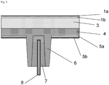
- a T-support profile is accommodated in a U-rib profile, the adhesive filling all 3 sides of the U-rib profile in a uniform thickness in the range of 1-5 mm (cf. Fig. 1 ).
- the adhesive is preferably a two-component polyurethane system with a Shore A 70 hardness.
- the metallic hinge components are connected to the carrier or to a layer connected to the carrier via a two-component polyurethane system with a Shore A 70 hardness.
- plastic composite components Another possible manufacturing process for such plastic composite components is a multi-component injection molding process, in which the support profile is already inserted into the appropriate shape and the plastic and the thermoplastic elastomer, which takes on the adhesive function, are injected.
- the composite component according to the invention has the advantage that very low demands are placed on the geometry of the support profile. Simple reinforcement plates can be inserted, tolerance deviations can be compensated for by the thickness of the adhesive layer.
- the simple geometry means there is no waste of material and the vertical arrangement of the support profile and the main surface of the base body means that less support profile is required. This means on the one hand cost efficiency due to lower material costs and lower manufacturing costs of the support profile, on the other hand weight reduction of the finished part.
- With the help of the adhesive layers occurring loads are evenly and evenly distributed in the plastic, so that there are no stress peaks.
- the new technology also enables components made of amorphous thermoplastics to be stiffened with metal profiles. The type and degree of stiffening and decoupling can be set very flexibly via the rib geometry and the adhesive layer thicknesses. The damping properties of the adhesive layer suppress vibrations and noise.
- Insulation materials can be applied to the inside of the components, optionally also between or above the reinforcing elements, for insulation and noise insulation, preferably in a "direct coating” process. Polyurethane systems are preferably used for this.
- the insulation layer is coated with a further lacquer or surface layer, so that an optically and haptically appealing inner surface of the component is created.
- Vehicle components in the sense of the present invention are tailgates.
- a tailgate based on a carrier (I) made from Makrolon® AG2677 from Bayer MaterialScience AG was produced by injection molding. According to the Figures 1 , 2nd and 3rd realized three different multilayer composites containing the carrier (I). In a preferred embodiment, the tailgate contains the functional elements Fig. 4 .
- Makrolon® AG2677 is a linear, UV-stabilized and easily demoldable polycarbonate based on bisphenol-A. Makrolon® AG2677 has a melt volume flow rate MVR according to ISO 1133 of 12.5 cm 3/10 min, measured at 300 ° C and 1.2 kg load on. The product is available from Bayer MaterialScience AG, Leverkusen.
- Makroblend® 7665 is an elastomer-modified polycarbonate, polyethylene terephthalate blend with 20% mineral filling with a melt volume flow rate MVR according to ISO 1133 of 14 cm 3/10 min, measured at 270 ° C and 5 kg load.
- the product is available from Bayer MaterialScience AG, Leverkusen.
- Makroblend® UT235M is a mineral-filled polyethylene terephthalate easily entformbares polycarbonate blend with a melt volume flow rate MVR according to ISO 1133 of 35 cm 3/10 min, measured at 270 ° C and 5 kg load.
- the product is available from Bayer MaterialScience AG, Leverkusen.
- Bayblend T95MF is a polycarbonate ABS blend with 9% mineral filling and a melt volume-flow rate MVR according to ISO 1133 of 18 cm 3/10 min, measured at 260 ° C and 5 kg load.
- the product is available from Bayer MaterialScience AG, Leverkusen.
- Scratch-resistant paint AS4700 is a thermally curing silicone-based paint containing isopropanol, n-butanol and methanol as a solvent, with a solids content of 25% by weight, a specific density of 0.92 and a viscosity measured at 25 ° C from 3-7.
- the product is available from Momentive Performance Materials GmbH, Leverkusen.
- SHP470 is a primer with a solids content of 7% by weight. a specific density of 0.94 and a viscosity at 25 ° C of 30 to 60 based on 1-methoxy-2-propanol as solvent.
- the product is available from Momentive Performance Materials GmbH, Leverkusen.
- Adhesive is a highly viscous, moisture-curing 1-component polyurethane system (e.g. DOW Betaseal 1842).
- the film 2 can also be dispensed with during manufacture.
- a spoiler (21) is formed in which a transparent area for the third brake light (12) is also integrated. Furthermore, transparent areas for indicators (14) and rear lights (16) are provided, as well as another transparent area underneath the windshield wiper mount (with integrated opening (20). Troughs for logo (18) and license plate (17) are also integrated.
Landscapes
- Engineering & Computer Science (AREA)
- Mechanical Engineering (AREA)
- Injection Moulding Of Plastics Or The Like (AREA)
- Laminated Bodies (AREA)
- Moulds For Moulding Plastics Or The Like (AREA)
Claims (14)
- Hayon (10), comprenant une pluralité d'éléments fonctionnels qui sont intégralement formés ou insérés dans le hayon, le hayon étant d'une seule pièce et sans joints et sans joints signifiant que la surface extérieure du composant ne comporte pas de joints ou de transitions d'une profondeur supérieure à 0,20 mm et comprend au moins un support continu en matière thermoplastique, le hayon comportant au moins une région transparente (12, 13, 14, 15, 16), caractérisé en ce qu'au moins une couche (4) est appliquée sur le support (3), laquelle forme des bords noirs et/ou des éléments de cadre de renforcement et le coefficient de dilatation thermique linéaire du matériau du bord noir et/ou de l'élément de cadre de renforcement dans la direction longitudinale est inférieur de 1 x 10⁻⁵ à 3 x 10⁻⁵ (mm/mm K) à celui du matériau de support.
- Hayon (10) selon la revendication 1, caractérisé en ce que le support (3) a une épaisseur de 3 à 7 mm, de préférence de 4 à 6 mm, de manière particulièrement préférée de 4,5 à 5,5 mm.
- Hayon (10) selon la revendication 1 ou la revendication 2, caractérisé en ce que l'épaisseur du support (3) sur tout le hayon varie de 10 % maximum, de préférence de 5 % maximum.
- Hayon (10) selon la revendication 1, caractérisé en ce que la matière thermoplastique du support (3) est du polycarbonate.
- Hayon (10) selon la revendication 4, caractérisé en ce que le polycarbonate a un poids moléculaire Mw de 25 000 à 27 000 g/mol.
- Hayon (10) selon l'une des revendications précédentes, caractérisé en ce que la couche (4) comprend des bords noirs ou des éléments de cadre de renforcement formés de mélanges qui contiennent(i) 10 à 90 % en poids de polycarbonate et 5 à 60 % en poids d'au moins un polyester ou(ii) des compositions comprenant A) et B),les parties en poids des composants A) et B) totalisant 100 etA) 60 à 95 parties en poids, sur la base de la somme des composants A) et B), d'au moins un polycarbonate aromatique etB) 5 à 40 parties en poids, sur la base de la somme des composants A) et B), d'au moins un acrylonitrile-butadiène-styrène,
le matériau du bord noir ou de l'élément de cadre de renforcement étant relié au support par une contre-injection partielle de ce dernier. - Hayon (10) selon l'une des revendications précédentes, caractérisé en ce que le hayon (10) comprend des éléments de renforcement mécanique (6, 7, 8) .
- Hayon (10) selon l'une des revendications précédentes, caractérisé en ce que le support (3) comporte au moins une autre couche, choisie dans le groupe comprenant- des couches destinées à augmenter la résistance aux rayures (1a, 1b),- des couches destinées à protéger contre les influences météorologiques,- des couches de coloration contenant des colorants et/ou des pigments (2),- des éléments de renforcement mécaniques (6, 7, 8),- des couches fonctionnelles choisies dans le groupe comprenant les couches antichocs, les couches antireflets et les couches de commande de transparence par électrochromie, thermotropie et thermochromie,- des couches d'isolation et d'insonorisation.
- Hayon selon l'une des revendications précédentes, caractérisé en ce qu'au moins un élément fonctionnel est inclus qui est choisi dans le groupe qui comprend des charnières, des éléments chauffants, des antennes, des fonctionnalités de fermeture, des boîtiers/réceptacles de lampe, des feux de plaque d'immatriculation, des feux de freinage surélevés, des logements d'essuie-glaces (et de moteur) (20), des évidements de plaque d'immatriculation (17), des évidements de logo (18), des spoilers (21), des lignes de style, des éléments structurels pour la gestion de l'eau, des réceptacles de plaque d'immatriculation à l'extérieur ou à l'intérieur et des modules solaires.
- Hayon (10) selon l'une des revendications précédentes, caractérisé en ce que le matériau de support situé dans des régions d'autres couches du côté d'application des couches est réduit en épaisseur de sorte que l'épaisseur de l'au moins une couche supplémentaire correspond à l'épaisseur réduite du matériau de support.
- Hayon (10) selon l'une des revendications précédentes, caractérisé en ce que différentes régions du support (3) sont réalisées par coulée de différents polymères thermoplastiques, au moins une portion étant transparente et une portion n'étant pas transparente.
- Hayon (10) selon l'une des revendications précédentes, caractérisé en ce qu'il comporte la structure en couches suivante :a) couche destinée à augmenter la résistance aux rayures (1a, 1b),b) film de protection IR (2),c) support (3),d) couche (4) qui forme des bords noirs et des éléments de cadre de renforcement,e) couche destinée à augmenter la résistance aux rayures (5)f) élément de renforcement mécanique formé d'un profilé de support (8) relié par un adhésif élastique (7) à un élément nervuré moulé (6).
- Hayon (10) selon l'une des revendications précédentes, caractérisé en ce que sans couture signifie que la surface extérieure du composant ne comporte pas de joints ou de transitions d'une profondeur supérieure à 0,15 mm, de préférence supérieure à 0,10 mm.
- Procédé de fabrication d'un hayon (10) selon la revendication 1, qui est d'une seule pièce et sans couture, sans couture signifiant que la surface extérieure du composant ne comporte pas de joints ou de transitions d'une profondeur supérieure à 0,20 mm et comprenant au moins un support continu (3) en matière thermoplastique, le hayon (10) comprenant au moins une région transparente (12, 13, 14, 15, 16), caractérisé en ce qu'au moins une couche (4) est appliquée sur le support (3), laquelle forme les bords noirs et/ou les éléments de cadre de renforcement, et le coefficient de dilatation thermique linéaire du matériau du bord noir et/ou de l'élément de cadre de renforcement dans la direction longitudinale est inférieur de 1 x 10⁻⁵ à 3 x 10⁻⁵ (mm/mm K) à celui du matériau de support, le procédé comprenant les étapes suivantes :- insérer éventuellement un film (2) dans un moule d'injection, fermer le moule,- injecter un support (3) puis refroidir à une température de composant < 145 °C,- faire tourner la cavité dans la position suivante pour créer un espace intermédiaire pour injecter un bord noir (4) et/ou l'élément de cadre de renforcement,- injecter le bord noir (4) et/ou l'élément de cadre de renforcement puis refroidir à une température de composant < 145 °C,-(i)• démouler,• refroidir le composant à la température ambiante,• revêtir par injection éventuellement le composant avec un primaire d'apprêt (1b, 5a),• laisser les solvants s'évaporer,• cuire/sécher le primaire d'apprêt (1b, 5a) à une température allant de 20 °C à 200 °C, de préférence de 40 °C à 130 °C,• refroidir à la température ambiante,• revêtir d'une couche de finition (la, 5b),• laisser le solvant s'évaporer,• cuire/sécher la couche de finition (la, 5b) à une température allant de 20 °C à 200 °C, de préférence de 40 °C à 130 °C,
en variante(ii)• faire tourner la cavité dans la position suivante pour injecter un système de peinture PU,• injecter le système de peinture PU,• démouler,- refroidir à température ambiante,- introduire un adhésif (7) entre les éléments nervurés (6),- incorporer un élément de renforcement (8) dans l'adhésif,- faire durcir l'adhésif.
Applications Claiming Priority (2)
| Application Number | Priority Date | Filing Date | Title |
|---|---|---|---|
| DE201010042939 DE102010042939A1 (de) | 2010-10-26 | 2010-10-26 | Fugenlose Heckklappe |
| PCT/EP2011/068667 WO2012055873A2 (fr) | 2010-10-26 | 2011-10-25 | Hayon sans joints |
Publications (2)
| Publication Number | Publication Date |
|---|---|
| EP2632750A2 EP2632750A2 (fr) | 2013-09-04 |
| EP2632750B1 true EP2632750B1 (fr) | 2020-04-22 |
Family
ID=44903203
Family Applications (1)
| Application Number | Title | Priority Date | Filing Date |
|---|---|---|---|
| EP11776742.6A Active EP2632750B1 (fr) | 2010-10-26 | 2011-10-25 | Hayon sans joints |
Country Status (7)
| Country | Link |
|---|---|
| US (1) | US9630478B2 (fr) |
| EP (1) | EP2632750B1 (fr) |
| JP (1) | JP6636232B2 (fr) |
| KR (1) | KR101916482B1 (fr) |
| CN (1) | CN103180155B (fr) |
| DE (1) | DE102010042939A1 (fr) |
| WO (1) | WO2012055873A2 (fr) |
Families Citing this family (32)
| Publication number | Priority date | Publication date | Assignee | Title |
|---|---|---|---|---|
| KR102374628B1 (ko) | 2013-10-07 | 2022-03-15 | 사빅 글로벌 테크놀러지스 비.브이. | 폐쇄 단면 구조, 중공 형상, 차량 부품 |
| JP5942973B2 (ja) * | 2013-12-18 | 2016-06-29 | トヨタ自動車株式会社 | 車両用部材の接着構造及びバックドアの接着構造 |
| PL3169502T3 (pl) | 2014-07-17 | 2020-02-28 | Saint-Gobain Glass France | Sposób wytwarzania montażowej części samochodowej z tworzywa sztucznego |
| JP6135651B2 (ja) * | 2014-12-02 | 2017-05-31 | トヨタ自動車株式会社 | 車両用バックドア構造 |
| JP6241413B2 (ja) * | 2014-12-25 | 2017-12-06 | マツダ株式会社 | 樹脂部材およびその製造方法 |
| CN204871254U (zh) * | 2014-12-30 | 2015-12-16 | 全耐塑料公司 | 机动车尾门板件及包含该板件的机动车 |
| DE102016102982A1 (de) * | 2015-03-03 | 2016-09-08 | Inglass S.P.A. | Verfahren zur Herstellung einer Komponente |
| JP6241443B2 (ja) * | 2015-03-30 | 2017-12-06 | マツダ株式会社 | 樹脂部材およびその製造方法 |
| US10690314B2 (en) | 2015-09-07 | 2020-06-23 | Sabic Global Technologies B.V. | Lighting systems of tailgates with plastic glazing |
| CN108025625B (zh) | 2015-09-07 | 2021-06-29 | 沙特基础工业全球技术公司 | 背门的塑料玻璃表面 |
| CN108025624B (zh) * | 2015-09-07 | 2021-04-27 | 沙特基础工业全球技术公司 | 车辆的后挡板的塑料装配玻璃 |
| EP3347184B1 (fr) * | 2015-09-07 | 2022-08-03 | SABIC Global Technologies B.V. | Moulage d'un vitrage en matière plastique de hayons |
| KR20180082561A (ko) | 2015-11-23 | 2018-07-18 | 사빅 글로벌 테크놀러지스 비.브이. | 플라스틱 글레이징을 갖는 윈도우를 위한 라이팅 시스템 |
| EP3257694B1 (fr) * | 2016-06-16 | 2020-05-06 | C.R.F. Società Consortile per Azioni | Hayon pour véhicules à moteur |
| DE102016213405A1 (de) | 2016-07-22 | 2018-01-25 | Bayerische Motoren Werke Aktiengesellschaft | Klappe für ein Kraftfahrzeug und Verfahren zur Herstellung einer Klappe, Kraftfahrzeug |
| US10377069B2 (en) | 2016-07-27 | 2019-08-13 | Dura Operating, Llc | Injection molded window and method |
| JP6380487B2 (ja) * | 2016-08-29 | 2018-08-29 | トヨタ自動車株式会社 | 車両用バックドア |
| WO2018060081A1 (fr) | 2016-09-27 | 2018-04-05 | Covestro Deutschland Ag | Pare-brise de véhicule automobile |
| KR102573487B1 (ko) * | 2016-12-06 | 2023-09-04 | 현대자동차주식회사 | 차량용 테일게이트 및 그 제조방법 |
| US11027312B2 (en) * | 2016-12-15 | 2021-06-08 | Covestro Deutschland Ag | Transparently coated polycarbonate component, its production and use |
| FR3060517B1 (fr) * | 2016-12-15 | 2019-06-14 | Compagnie Plastic Omnium | Element automobile en materiau thermodurcissable comprenant au moins un clip |
| CN107336749B (zh) * | 2016-12-28 | 2018-08-07 | 浙江中车电车有限公司 | 一种车用后尾机构 |
| DE102017216838A1 (de) * | 2017-09-22 | 2019-03-28 | Ford Global Technologies, Llc | Motorhaube aus Kunststoffmaterial |
| DE102017223726A1 (de) * | 2017-12-22 | 2019-06-27 | Volkswagen Aktiengesellschaft | Anbauteil für ein Fahrzeug sowie Fahrzeug mit einem derartigen Anbauteil |
| JP6974190B2 (ja) * | 2018-01-17 | 2021-12-01 | トヨタ自動車株式会社 | 車両の樹脂バックドア |
| EP3743316B1 (fr) | 2018-01-26 | 2021-10-27 | SABIC Global Technologies B.V. | Panneau d'extrémité avant pour véhicule électrique |
| FR3079771B1 (fr) * | 2018-04-10 | 2021-09-10 | Plastic Omnium Cie | Piece de carrosserie comportant un insert surmoule en polyolefine amorphe |
| FR3083484B1 (fr) * | 2018-07-05 | 2021-04-09 | Renault Sas | Dispositif de structure de porte de coffre de vehicule |
| US10780927B2 (en) * | 2018-10-05 | 2020-09-22 | Toyota Motor Engineering & Manufacturing North America, Inc. | Spoiler apparatus for use with vehicles |
| FR3087728B1 (fr) * | 2018-10-24 | 2020-11-06 | Plastic Omnium Cie | Piece de carrosserie comprenant un element de decoration |
| DE102019109759A1 (de) * | 2019-04-12 | 2020-10-15 | HELLA GmbH & Co. KGaA | Verfahren zur Herstellung eines Metall-Kunststoff-Verbundbauteils sowie Metall-Kunststoff-Verbundbauteil |
| JP7322535B2 (ja) * | 2019-06-13 | 2023-08-08 | 株式会社レゾナック | 自動車用バックドア及びその製造方法 |
Citations (12)
| Publication number | Priority date | Publication date | Assignee | Title |
|---|---|---|---|---|
| GB2123841A (en) | 1982-07-02 | 1984-02-08 | Ppg Industries Inc | Abrasion resistant thin polyurethane coating |
| US4822098A (en) | 1986-11-05 | 1989-04-18 | Ford Motor Company | Double-walled structural body panel for motor vehicle |
| US20040036315A1 (en) | 2002-05-01 | 2004-02-26 | Idemitsu Petrochemical Co., Ltd. | Two-color molding and molding method thereof |
| US6833193B2 (en) | 2000-03-08 | 2004-12-21 | Bayer Aktiengesellschaft | Polycarbonate molded bodies with improved optical properties |
| US20050170191A1 (en) | 2002-02-20 | 2005-08-04 | Saint-Gobain Glass France | Glass pane with rigid element optionally incorporated in an overmoulded plastic part |
| US20060017304A1 (en) | 2004-07-20 | 2006-01-26 | Volkswagen Ag | End region of a vehicle with a lid |
| WO2006053547A2 (fr) | 2004-11-17 | 2006-05-26 | Brose Fahrzeugteile Gmbh & Co. Kg, Coburg | Capot pour un vehicule automobile |
| US20060151911A1 (en) | 2004-12-24 | 2006-07-13 | Olaf Zollner | Process and mold for molding and coating a substrate |
| EP1787841A2 (fr) | 2005-11-22 | 2007-05-23 | HONDA MOTOR CO., Ltd. | Structure résineusse pour le carénage de véhicules |
| JP2007223445A (ja) | 2006-02-23 | 2007-09-06 | Mitsubishi Motors Corp | 車両の跳上げ式窓構造 |
| US20090304970A1 (en) | 2006-09-12 | 2009-12-10 | Hiroyuki Imaizumi | Panel-shaped molded product |
| JP4495938B2 (ja) | 2003-09-30 | 2010-07-07 | 出光興産株式会社 | 二色成形品の製造方法 |
Family Cites Families (50)
| Publication number | Priority date | Publication date | Assignee | Title |
|---|---|---|---|---|
| DE1031512B (de) | 1955-12-21 | 1958-06-04 | Bayer Ag | Verfahren zur Herstellung von hochmolekularen faser- und filmbildenden Polycarbonaten |
| US3644574A (en) | 1969-07-17 | 1972-02-22 | Eastman Kodak Co | Shaped articles of blends of polyesters and polyvinyls |
| US4013613A (en) | 1971-10-01 | 1977-03-22 | General Electric Company | Reinforced intercrystalline thermoplastic polyester compositions |
| DE2500092C3 (de) | 1975-01-03 | 1978-10-12 | Bayer Ag, 5090 Leverkusen | Verzweigte, hochmolekulare, thermoplastische und lösliche Polycarbonate |
| US4185009A (en) | 1975-01-03 | 1980-01-22 | Bayer Aktiengesellschaft | Branched, high-molecular weight thermoplastic polycarbonates |
| US4101513A (en) | 1977-02-02 | 1978-07-18 | Minnesota Mining And Manufacturing Company | Catalyst for condensation of hydrolyzable silanes and storage stable compositions thereof |
| DE2948524A1 (de) * | 1979-12-01 | 1981-06-04 | Daimler Benz Ag | Kraftwagen mit einem hochschwenkbaren hinteren karosserieabschluss |
| US4395463A (en) | 1980-06-03 | 1983-07-26 | General Electric Company | Article comprising silicone resin coated, methacrylate-primed substrate |
| DE8233007U1 (de) | 1982-11-25 | 1983-03-24 | Röhm GmbH, 6100 Darmstadt | Polycarbonat-kunststofftafel |
| DE3244953C2 (de) | 1982-12-04 | 1984-11-29 | Röhm GmbH, 6100 Darmstadt | Verfahren zur Herstellung einer Hohlkammerkunststofftafel |
| DE3913832A1 (de) * | 1988-05-11 | 1989-11-23 | Volkswagen Ag | Karosserieteil nach art einer heckklappe oder -tuer |
| US5041313A (en) | 1990-05-11 | 1991-08-20 | General Electric Company | Method for making silicone hardcoat composites and primer compositions |
| US5367044A (en) | 1990-10-12 | 1994-11-22 | General Electric Company | Blow molded article molded from a composition comprising a randomly branched aromatic polymer |
| TW222292B (fr) | 1991-02-21 | 1994-04-11 | Ciba Geigy Ag | |
| DE4118232A1 (de) | 1991-06-04 | 1992-12-10 | Bayer Ag | Kontinuierliche herstellung von polycarbonaten |
| CA2093686A1 (fr) | 1992-05-11 | 1993-11-12 | Gautam A. Patel | Compositions pour revetement de silicone sans appret, thermodurcissables, et composites thermoplastiques |
| DE4240313A1 (de) | 1992-12-01 | 1994-06-09 | Bayer Ag | Polycarbonate für optische Datenträger |
| US5391795A (en) | 1994-02-18 | 1995-02-21 | General Electric Company | Silylated agents useful for absorbing ultraviolet light |
| DE69509952T2 (de) | 1994-03-04 | 1999-11-04 | General Electric Co., Schenectady | Beschichtungen geeignet zur Absorption von Ultraviolettlicht |
| CN1046707C (zh) | 1994-11-10 | 1999-11-24 | 巴斯福股份公司 | 2-氰基丙烯酸酯 |
| DE4444868A1 (de) | 1994-12-16 | 1996-06-20 | Bayer Ag | UV-geschützte, mehrschichtige Polycarbonatplatten |
| CA2203595A1 (fr) | 1996-04-26 | 1997-10-26 | Robert F. Hurley | Ruban de polyolefine reticule |
| DE59702969D1 (de) | 1996-10-30 | 2001-03-08 | Ciba Sc Holding Ag | Stabilisatorkombination für das Rotomolding-Verfahren |
| JP3784497B2 (ja) | 1997-05-29 | 2006-06-14 | 三菱エンジニアリングプラスチックス株式会社 | 熱可塑性樹脂製グレージング材およびその製造方法 |
| DE19943642A1 (de) | 1999-09-13 | 2001-03-15 | Bayer Ag | Behälter |
| DE10006208A1 (de) | 2000-02-11 | 2001-08-16 | Bayer Ag | IR-absorbierende Zusammensetzungen |
| DE10022037A1 (de) | 2000-05-05 | 2001-11-08 | Bayer Ag | IR-absorbierende Zusammensetzungen |
| US6228973B1 (en) | 2000-06-02 | 2001-05-08 | General Electric Company | Method for preparing high molecular weight polycarbonate |
| DE10047483A1 (de) | 2000-09-26 | 2002-04-11 | Bayer Ag | Verwendung von Copolycarbonaten |
| US20030214070A1 (en) | 2002-05-08 | 2003-11-20 | General Electric Company | Multiwall polycarbonate sheet and method for its production |
| US6988757B2 (en) * | 2002-08-28 | 2006-01-24 | Dow Global Technologies Inc. | Composite panel and method of forming the same |
| EP1308084A1 (fr) | 2002-10-02 | 2003-05-07 | Ciba SC Holding AG | Combinaison UV-absorbante avec un effet synergistique |
| DE10311063A1 (de) | 2003-03-13 | 2004-09-23 | Basf Ag | Verwendung einer Stabilisatormischung in thermoplastischen Formmassen |
| JP2004331883A (ja) * | 2003-05-09 | 2004-11-25 | Nissan Motor Co Ltd | 複合樹脂組成物中間体、複合樹脂組成物、複合樹脂組成物中間体の製造方法、及び複合樹脂組成物の製造方法 |
| US20050165148A1 (en) | 2004-01-28 | 2005-07-28 | Bogerd Jos V.D. | Infra-red radiation absorption articles and method of manufacture thereof |
| US7365124B2 (en) | 2004-03-31 | 2008-04-29 | General Electric Company | Flame retardant resin blends based on polymers derived from 2-hydrocarbyl-3,3-bis(4-hydroxyaryl)phthalimidine monomers |
| DE102004022673A1 (de) | 2004-05-07 | 2005-11-24 | Bayer Materialscience Ag | Copolycarbonate mit verbesserter Fließfähigkeit |
| WO2006103906A1 (fr) | 2005-03-28 | 2006-10-05 | Mitsubishi Engineering-Plastics Corporation | Composition de résine de polycarbonate et produit moulé faisant écran à un rayonnement chaud |
| DE102005017023A1 (de) | 2005-04-13 | 2006-10-19 | Bayer Materialscience Ag | UV-stabilisierte Polycarbonatformkörper |
| DE102006046330A1 (de) | 2006-09-28 | 2008-04-03 | Bayer Materialscience Ag | Polycarbonate und Copolycarbonate mit verbesserter Metallhaftung |
| GB2444053A (en) | 2006-11-23 | 2008-05-28 | Eques Coatings | Hybrid UV-curable resins |
| US7857905B2 (en) | 2007-03-05 | 2010-12-28 | Momentive Performance Materials Inc. | Flexible thermal cure silicone hardcoats |
| DE102007011069A1 (de) | 2007-03-07 | 2008-09-11 | Bayer Materialscience Ag | Polycarbonatzusammensetzung enthaltend UV-Absorber |
| JP5089770B2 (ja) * | 2007-05-01 | 2012-12-05 | エグザテック・リミテッド・ライアビリティー・カンパニー | Uv硬化性印刷パターンを有するプラスチックグレージングパネル及びそのパネルを作製する方法 |
| JP2009056893A (ja) * | 2007-08-30 | 2009-03-19 | Daikyo Nishikawa Kk | 車両のバックドア |
| JP2010099870A (ja) * | 2008-10-21 | 2010-05-06 | Polymatech Co Ltd | 装飾成形品の製造方法および装飾成形品 |
| CN102245414B (zh) | 2008-12-12 | 2013-11-13 | 大协西川株式会社 | 车辆用后背门 |
| WO2010086385A1 (fr) * | 2009-01-28 | 2010-08-05 | Nexam Chemicals Ab | Polycarbonate aromatique réticulable |
| DE102009039631A1 (de) * | 2009-09-01 | 2011-03-03 | Daimler Ag | Heckklappe eines Kraftfahrzeugs mit illuminiertem Kennzeichen |
| MX2012013445A (es) | 2010-05-21 | 2013-12-16 | Sidel Spa Con Socio Unico | Metodo y linea para el transporte de envases, en particular botellas. |
-
2010
- 2010-10-26 DE DE201010042939 patent/DE102010042939A1/de not_active Withdrawn
-
2011
- 2011-10-25 WO PCT/EP2011/068667 patent/WO2012055873A2/fr active Application Filing
- 2011-10-25 EP EP11776742.6A patent/EP2632750B1/fr active Active
- 2011-10-25 KR KR1020137010569A patent/KR101916482B1/ko active IP Right Grant
- 2011-10-25 JP JP2013535407A patent/JP6636232B2/ja active Active
- 2011-10-25 US US13/878,545 patent/US9630478B2/en active Active
- 2011-10-25 CN CN201180051850.9A patent/CN103180155B/zh active Active
Patent Citations (12)
| Publication number | Priority date | Publication date | Assignee | Title |
|---|---|---|---|---|
| GB2123841A (en) | 1982-07-02 | 1984-02-08 | Ppg Industries Inc | Abrasion resistant thin polyurethane coating |
| US4822098A (en) | 1986-11-05 | 1989-04-18 | Ford Motor Company | Double-walled structural body panel for motor vehicle |
| US6833193B2 (en) | 2000-03-08 | 2004-12-21 | Bayer Aktiengesellschaft | Polycarbonate molded bodies with improved optical properties |
| US20050170191A1 (en) | 2002-02-20 | 2005-08-04 | Saint-Gobain Glass France | Glass pane with rigid element optionally incorporated in an overmoulded plastic part |
| US20040036315A1 (en) | 2002-05-01 | 2004-02-26 | Idemitsu Petrochemical Co., Ltd. | Two-color molding and molding method thereof |
| JP4495938B2 (ja) | 2003-09-30 | 2010-07-07 | 出光興産株式会社 | 二色成形品の製造方法 |
| US20060017304A1 (en) | 2004-07-20 | 2006-01-26 | Volkswagen Ag | End region of a vehicle with a lid |
| WO2006053547A2 (fr) | 2004-11-17 | 2006-05-26 | Brose Fahrzeugteile Gmbh & Co. Kg, Coburg | Capot pour un vehicule automobile |
| US20060151911A1 (en) | 2004-12-24 | 2006-07-13 | Olaf Zollner | Process and mold for molding and coating a substrate |
| EP1787841A2 (fr) | 2005-11-22 | 2007-05-23 | HONDA MOTOR CO., Ltd. | Structure résineusse pour le carénage de véhicules |
| JP2007223445A (ja) | 2006-02-23 | 2007-09-06 | Mitsubishi Motors Corp | 車両の跳上げ式窓構造 |
| US20090304970A1 (en) | 2006-09-12 | 2009-12-10 | Hiroyuki Imaizumi | Panel-shaped molded product |
Non-Patent Citations (5)
| Title |
|---|
| ANONYMOUS: "Auto Glazing: Window of Opportunity for Molders ", PTONLINE, 1 April 2006 (2006-04-01), XP055981840, Retrieved from the Internet <URL:https://www.ptonline.com/articles/auto-g> [retrieved on 20221116] |
| ANONYMOUS: "DATASHEET Bayblend® T95 MF (PC+ABS)-T9 ", ALBIS COVESTRO DEUTSCHLAND AG, 22 December 2020 (2020-12-22), XP055981828, [retrieved on 20221116] |
| ANONYMOUS: "DATASHEET Makroblend® UT235 M", COVESTRO, 15 January 2019 (2019-01-15), XP055981831, [retrieved on 20221116] |
| ANONYMOUS: "Datasheet Makrolon® AG2677", COVESTRO, 3 December 2018 (2018-12-03), XP055981833, [retrieved on 20221116] |
| ANONYMOUS: "Makroblend DP 7665", BAYER MATERIAL SCIENCE, 25 April 2009 (2009-04-25), XP055981832, [retrieved on 20221116] |
Also Published As
| Publication number | Publication date |
|---|---|
| KR20130120468A (ko) | 2013-11-04 |
| WO2012055873A2 (fr) | 2012-05-03 |
| JP2014502229A (ja) | 2014-01-30 |
| EP2632750A2 (fr) | 2013-09-04 |
| DE102010042939A1 (de) | 2012-04-26 |
| KR101916482B1 (ko) | 2018-11-07 |
| CN103180155B (zh) | 2017-11-14 |
| CN103180155A (zh) | 2013-06-26 |
| WO2012055873A3 (fr) | 2012-07-26 |
| US9630478B2 (en) | 2017-04-25 |
| JP6636232B2 (ja) | 2020-01-29 |
| US20130280452A1 (en) | 2013-10-24 |
Similar Documents
| Publication | Publication Date | Title |
|---|---|---|
| EP2632750B1 (fr) | Hayon sans joints | |
| EP1427627B1 (fr) | Composants composites profiles creux | |
| EP3169502B1 (fr) | Procédé de fabrication d'une pièce rapportée de véhicule en matière plastique | |
| EP3083075B1 (fr) | Structure multicouches en polycarbonate et écran de polycarbonate avec une qualité optique élevée, une résistance élevée à l'abrasion et une résistance aux intempéries | |
| EP3191297B1 (fr) | Pare-brise pour véhicules automobiles | |
| EP3849771B1 (fr) | Surmoulage de feuille tempéré dynamique par injection | |
| EP3233551B1 (fr) | Vitre en polymère ayant un profil d'étanchéité extrudé | |
| EP3554722A1 (fr) | Composant en polycarbonate revêtu transparent, sa fabrication et son utilisation | |
| EP2758276B1 (fr) | Habillage de montant pour véhicules automobiles | |
| EP2790842B1 (fr) | Pièce usinée polymère pour le revêtement de canal | |
| EP3519217B1 (fr) | Véhicule automobile avec deux a-montants et un pare-brise | |
| EP2758278B1 (fr) | Habillage de montant pour véhicules automobiles | |
| US12076970B2 (en) | Two shot molding with isosorbide based polycarbonate | |
| EP2716440A1 (fr) | Composant composite |
Legal Events
| Date | Code | Title | Description |
|---|---|---|---|
| PUAI | Public reference made under article 153(3) epc to a published international application that has entered the european phase |
Free format text: ORIGINAL CODE: 0009012 |
|
| 17P | Request for examination filed |
Effective date: 20130527 |
|
| AK | Designated contracting states |
Kind code of ref document: A2 Designated state(s): AL AT BE BG CH CY CZ DE DK EE ES FI FR GB GR HR HU IE IS IT LI LT LU LV MC MK MT NL NO PL PT RO RS SE SI SK SM TR |
|
| DAX | Request for extension of the european patent (deleted) | ||
| 17Q | First examination report despatched |
Effective date: 20150821 |
|
| RAP1 | Party data changed (applicant data changed or rights of an application transferred) |
Owner name: COVESTRO DEUTSCHLAND AG |
|
| STAA | Information on the status of an ep patent application or granted ep patent |
Free format text: STATUS: EXAMINATION IS IN PROGRESS |
|
| GRAP | Despatch of communication of intention to grant a patent |
Free format text: ORIGINAL CODE: EPIDOSNIGR1 |
|
| STAA | Information on the status of an ep patent application or granted ep patent |
Free format text: STATUS: GRANT OF PATENT IS INTENDED |
|
| INTG | Intention to grant announced |
Effective date: 20200108 |
|
| GRAS | Grant fee paid |
Free format text: ORIGINAL CODE: EPIDOSNIGR3 |
|
| GRAA | (expected) grant |
Free format text: ORIGINAL CODE: 0009210 |
|
| STAA | Information on the status of an ep patent application or granted ep patent |
Free format text: STATUS: THE PATENT HAS BEEN GRANTED |
|
| AK | Designated contracting states |
Kind code of ref document: B1 Designated state(s): AL AT BE BG CH CY CZ DE DK EE ES FI FR GB GR HR HU IE IS IT LI LT LU LV MC MK MT NL NO PL PT RO RS SE SI SK SM TR |
|
| REG | Reference to a national code |
Ref country code: GB Ref legal event code: FG4D Free format text: NOT ENGLISH |
|
| REG | Reference to a national code |
Ref country code: CH Ref legal event code: EP |
|
| REG | Reference to a national code |
Ref country code: IE Ref legal event code: FG4D Free format text: LANGUAGE OF EP DOCUMENT: GERMAN |
|
| REG | Reference to a national code |
Ref country code: DE Ref legal event code: R096 Ref document number: 502011016636 Country of ref document: DE |
|
| REG | Reference to a national code |
Ref country code: AT Ref legal event code: REF Ref document number: 1259633 Country of ref document: AT Kind code of ref document: T Effective date: 20200515 |
|
| REG | Reference to a national code |
Ref country code: LT Ref legal event code: MG4D |
|
| REG | Reference to a national code |
Ref country code: NL Ref legal event code: MP Effective date: 20200422 |
|
| PG25 | Lapsed in a contracting state [announced via postgrant information from national office to epo] |
Ref country code: SE Free format text: LAPSE BECAUSE OF FAILURE TO SUBMIT A TRANSLATION OF THE DESCRIPTION OR TO PAY THE FEE WITHIN THE PRESCRIBED TIME-LIMIT Effective date: 20200422 Ref country code: IS Free format text: LAPSE BECAUSE OF FAILURE TO SUBMIT A TRANSLATION OF THE DESCRIPTION OR TO PAY THE FEE WITHIN THE PRESCRIBED TIME-LIMIT Effective date: 20200822 Ref country code: NO Free format text: LAPSE BECAUSE OF FAILURE TO SUBMIT A TRANSLATION OF THE DESCRIPTION OR TO PAY THE FEE WITHIN THE PRESCRIBED TIME-LIMIT Effective date: 20200722 Ref country code: GR Free format text: LAPSE BECAUSE OF FAILURE TO SUBMIT A TRANSLATION OF THE DESCRIPTION OR TO PAY THE FEE WITHIN THE PRESCRIBED TIME-LIMIT Effective date: 20200723 Ref country code: LT Free format text: LAPSE BECAUSE OF FAILURE TO SUBMIT A TRANSLATION OF THE DESCRIPTION OR TO PAY THE FEE WITHIN THE PRESCRIBED TIME-LIMIT Effective date: 20200422 Ref country code: FI Free format text: LAPSE BECAUSE OF FAILURE TO SUBMIT A TRANSLATION OF THE DESCRIPTION OR TO PAY THE FEE WITHIN THE PRESCRIBED TIME-LIMIT Effective date: 20200422 Ref country code: PT Free format text: LAPSE BECAUSE OF FAILURE TO SUBMIT A TRANSLATION OF THE DESCRIPTION OR TO PAY THE FEE WITHIN THE PRESCRIBED TIME-LIMIT Effective date: 20200824 Ref country code: NL Free format text: LAPSE BECAUSE OF FAILURE TO SUBMIT A TRANSLATION OF THE DESCRIPTION OR TO PAY THE FEE WITHIN THE PRESCRIBED TIME-LIMIT Effective date: 20200422 |
|
| PG25 | Lapsed in a contracting state [announced via postgrant information from national office to epo] |
Ref country code: LV Free format text: LAPSE BECAUSE OF FAILURE TO SUBMIT A TRANSLATION OF THE DESCRIPTION OR TO PAY THE FEE WITHIN THE PRESCRIBED TIME-LIMIT Effective date: 20200422 Ref country code: HR Free format text: LAPSE BECAUSE OF FAILURE TO SUBMIT A TRANSLATION OF THE DESCRIPTION OR TO PAY THE FEE WITHIN THE PRESCRIBED TIME-LIMIT Effective date: 20200422 Ref country code: RS Free format text: LAPSE BECAUSE OF FAILURE TO SUBMIT A TRANSLATION OF THE DESCRIPTION OR TO PAY THE FEE WITHIN THE PRESCRIBED TIME-LIMIT Effective date: 20200422 Ref country code: BG Free format text: LAPSE BECAUSE OF FAILURE TO SUBMIT A TRANSLATION OF THE DESCRIPTION OR TO PAY THE FEE WITHIN THE PRESCRIBED TIME-LIMIT Effective date: 20200722 |
|
| PG25 | Lapsed in a contracting state [announced via postgrant information from national office to epo] |
Ref country code: AL Free format text: LAPSE BECAUSE OF FAILURE TO SUBMIT A TRANSLATION OF THE DESCRIPTION OR TO PAY THE FEE WITHIN THE PRESCRIBED TIME-LIMIT Effective date: 20200422 |
|
| REG | Reference to a national code |
Ref country code: DE Ref legal event code: R026 Ref document number: 502011016636 Country of ref document: DE |
|
| PG25 | Lapsed in a contracting state [announced via postgrant information from national office to epo] |
Ref country code: SM Free format text: LAPSE BECAUSE OF FAILURE TO SUBMIT A TRANSLATION OF THE DESCRIPTION OR TO PAY THE FEE WITHIN THE PRESCRIBED TIME-LIMIT Effective date: 20200422 Ref country code: ES Free format text: LAPSE BECAUSE OF FAILURE TO SUBMIT A TRANSLATION OF THE DESCRIPTION OR TO PAY THE FEE WITHIN THE PRESCRIBED TIME-LIMIT Effective date: 20200422 Ref country code: CZ Free format text: LAPSE BECAUSE OF FAILURE TO SUBMIT A TRANSLATION OF THE DESCRIPTION OR TO PAY THE FEE WITHIN THE PRESCRIBED TIME-LIMIT Effective date: 20200422 Ref country code: RO Free format text: LAPSE BECAUSE OF FAILURE TO SUBMIT A TRANSLATION OF THE DESCRIPTION OR TO PAY THE FEE WITHIN THE PRESCRIBED TIME-LIMIT Effective date: 20200422 Ref country code: DK Free format text: LAPSE BECAUSE OF FAILURE TO SUBMIT A TRANSLATION OF THE DESCRIPTION OR TO PAY THE FEE WITHIN THE PRESCRIBED TIME-LIMIT Effective date: 20200422 Ref country code: EE Free format text: LAPSE BECAUSE OF FAILURE TO SUBMIT A TRANSLATION OF THE DESCRIPTION OR TO PAY THE FEE WITHIN THE PRESCRIBED TIME-LIMIT Effective date: 20200422 |
|
| PLBI | Opposition filed |
Free format text: ORIGINAL CODE: 0009260 |
|
| PLAX | Notice of opposition and request to file observation + time limit sent |
Free format text: ORIGINAL CODE: EPIDOSNOBS2 |
|
| PG25 | Lapsed in a contracting state [announced via postgrant information from national office to epo] |
Ref country code: PL Free format text: LAPSE BECAUSE OF FAILURE TO SUBMIT A TRANSLATION OF THE DESCRIPTION OR TO PAY THE FEE WITHIN THE PRESCRIBED TIME-LIMIT Effective date: 20200422 Ref country code: SK Free format text: LAPSE BECAUSE OF FAILURE TO SUBMIT A TRANSLATION OF THE DESCRIPTION OR TO PAY THE FEE WITHIN THE PRESCRIBED TIME-LIMIT Effective date: 20200422 |
|
| 26 | Opposition filed |
Opponent name: SABIC GLOBAL TECHNOLOGIES B.V. Effective date: 20210119 |
|
| PG25 | Lapsed in a contracting state [announced via postgrant information from national office to epo] |
Ref country code: SI Free format text: LAPSE BECAUSE OF FAILURE TO SUBMIT A TRANSLATION OF THE DESCRIPTION OR TO PAY THE FEE WITHIN THE PRESCRIBED TIME-LIMIT Effective date: 20200422 |
|
| REG | Reference to a national code |
Ref country code: CH Ref legal event code: PL |
|
| PLBB | Reply of patent proprietor to notice(s) of opposition received |
Free format text: ORIGINAL CODE: EPIDOSNOBS3 |
|
| PG25 | Lapsed in a contracting state [announced via postgrant information from national office to epo] |
Ref country code: LU Free format text: LAPSE BECAUSE OF NON-PAYMENT OF DUE FEES Effective date: 20201025 Ref country code: MC Free format text: LAPSE BECAUSE OF FAILURE TO SUBMIT A TRANSLATION OF THE DESCRIPTION OR TO PAY THE FEE WITHIN THE PRESCRIBED TIME-LIMIT Effective date: 20200422 |
|
| REG | Reference to a national code |
Ref country code: BE Ref legal event code: MM Effective date: 20201031 |
|
| PG25 | Lapsed in a contracting state [announced via postgrant information from national office to epo] |
Ref country code: FR Free format text: LAPSE BECAUSE OF NON-PAYMENT OF DUE FEES Effective date: 20201031 |
|
| PG25 | Lapsed in a contracting state [announced via postgrant information from national office to epo] |
Ref country code: BE Free format text: LAPSE BECAUSE OF NON-PAYMENT OF DUE FEES Effective date: 20201031 Ref country code: CH Free format text: LAPSE BECAUSE OF NON-PAYMENT OF DUE FEES Effective date: 20201031 Ref country code: LI Free format text: LAPSE BECAUSE OF NON-PAYMENT OF DUE FEES Effective date: 20201031 |
|
| PG25 | Lapsed in a contracting state [announced via postgrant information from national office to epo] |
Ref country code: IE Free format text: LAPSE BECAUSE OF NON-PAYMENT OF DUE FEES Effective date: 20201025 |
|
| REG | Reference to a national code |
Ref country code: AT Ref legal event code: MM01 Ref document number: 1259633 Country of ref document: AT Kind code of ref document: T Effective date: 20201025 |
|
| PG25 | Lapsed in a contracting state [announced via postgrant information from national office to epo] |
Ref country code: AT Free format text: LAPSE BECAUSE OF NON-PAYMENT OF DUE FEES Effective date: 20201025 |
|
| PG25 | Lapsed in a contracting state [announced via postgrant information from national office to epo] |
Ref country code: TR Free format text: LAPSE BECAUSE OF FAILURE TO SUBMIT A TRANSLATION OF THE DESCRIPTION OR TO PAY THE FEE WITHIN THE PRESCRIBED TIME-LIMIT Effective date: 20200422 Ref country code: MT Free format text: LAPSE BECAUSE OF FAILURE TO SUBMIT A TRANSLATION OF THE DESCRIPTION OR TO PAY THE FEE WITHIN THE PRESCRIBED TIME-LIMIT Effective date: 20200422 Ref country code: CY Free format text: LAPSE BECAUSE OF FAILURE TO SUBMIT A TRANSLATION OF THE DESCRIPTION OR TO PAY THE FEE WITHIN THE PRESCRIBED TIME-LIMIT Effective date: 20200422 |
|
| REG | Reference to a national code |
Ref country code: DE Ref legal event code: R100 Ref document number: 502011016636 Country of ref document: DE |
|
| PG25 | Lapsed in a contracting state [announced via postgrant information from national office to epo] |
Ref country code: MK Free format text: LAPSE BECAUSE OF FAILURE TO SUBMIT A TRANSLATION OF THE DESCRIPTION OR TO PAY THE FEE WITHIN THE PRESCRIBED TIME-LIMIT Effective date: 20200422 |
|
| PLCK | Communication despatched that opposition was rejected |
Free format text: ORIGINAL CODE: EPIDOSNREJ1 |
|
| PLAB | Opposition data, opponent's data or that of the opponent's representative modified |
Free format text: ORIGINAL CODE: 0009299OPPO |
|
| R26 | Opposition filed (corrected) |
Opponent name: SABIC GLOBAL TECHNOLOGIES B.V. Effective date: 20210119 |
|
| PLBN | Opposition rejected |
Free format text: ORIGINAL CODE: 0009273 |
|
| STAA | Information on the status of an ep patent application or granted ep patent |
Free format text: STATUS: OPPOSITION REJECTED |
|
| 27O | Opposition rejected |
Effective date: 20220615 |
|
| PGFP | Annual fee paid to national office [announced via postgrant information from national office to epo] |
Ref country code: IT Payment date: 20230926 Year of fee payment: 13 Ref country code: DE Payment date: 20230919 Year of fee payment: 13 |
|
| PGFP | Annual fee paid to national office [announced via postgrant information from national office to epo] |
Ref country code: GB Payment date: 20240919 Year of fee payment: 14 |