EP2631191A1 - Bedruckte nahtlose dose und verfahren zu ihrer herstellung - Google Patents
Bedruckte nahtlose dose und verfahren zu ihrer herstellung Download PDFInfo
- Publication number
- EP2631191A1 EP2631191A1 EP11834246.8A EP11834246A EP2631191A1 EP 2631191 A1 EP2631191 A1 EP 2631191A1 EP 11834246 A EP11834246 A EP 11834246A EP 2631191 A1 EP2631191 A1 EP 2631191A1
- Authority
- EP
- European Patent Office
- Prior art keywords
- printed
- ink
- printing
- seamless
- plate
- Prior art date
- Legal status (The legal status is an assumption and is not a legal conclusion. Google has not performed a legal analysis and makes no representation as to the accuracy of the status listed.)
- Granted
Links
- 238000000034 method Methods 0.000 title claims description 31
- 238000004519 manufacturing process Methods 0.000 title description 2
- 238000007639 printing Methods 0.000 claims abstract description 157
- 238000007641 inkjet printing Methods 0.000 claims abstract description 114
- 239000002966 varnish Substances 0.000 claims abstract description 33
- 239000000976 ink Substances 0.000 claims description 120
- 239000011248 coating agent Substances 0.000 claims description 65
- 238000000576 coating method Methods 0.000 claims description 65
- 239000003086 colorant Substances 0.000 claims description 10
- 238000004826 seaming Methods 0.000 claims description 6
- 238000011156 evaluation Methods 0.000 description 18
- 238000007645 offset printing Methods 0.000 description 10
- 238000001723 curing Methods 0.000 description 9
- 230000000052 comparative effect Effects 0.000 description 8
- 229910052751 metal Inorganic materials 0.000 description 7
- 239000002184 metal Substances 0.000 description 7
- GWEVSGVZZGPLCZ-UHFFFAOYSA-N Titan oxide Chemical compound O=[Ti]=O GWEVSGVZZGPLCZ-UHFFFAOYSA-N 0.000 description 6
- 238000001035 drying Methods 0.000 description 6
- 238000013007 heat curing Methods 0.000 description 6
- 229920005989 resin Polymers 0.000 description 6
- 239000011347 resin Substances 0.000 description 6
- 239000002904 solvent Substances 0.000 description 6
- 238000010438 heat treatment Methods 0.000 description 5
- 230000000694 effects Effects 0.000 description 4
- 239000002932 luster Substances 0.000 description 4
- 239000000049 pigment Substances 0.000 description 4
- OGIDPMRJRNCKJF-UHFFFAOYSA-N titanium oxide Inorganic materials [Ti]=O OGIDPMRJRNCKJF-UHFFFAOYSA-N 0.000 description 4
- 229910000831 Steel Inorganic materials 0.000 description 3
- 235000013361 beverage Nutrition 0.000 description 3
- 230000002950 deficient Effects 0.000 description 3
- 238000010586 diagram Methods 0.000 description 3
- 238000010409 ironing Methods 0.000 description 3
- 239000000463 material Substances 0.000 description 3
- 239000007787 solid Substances 0.000 description 3
- 239000010959 steel Substances 0.000 description 3
- 238000005406 washing Methods 0.000 description 3
- 229910052782 aluminium Inorganic materials 0.000 description 2
- XAGFODPZIPBFFR-UHFFFAOYSA-N aluminium Chemical compound [Al] XAGFODPZIPBFFR-UHFFFAOYSA-N 0.000 description 2
- 229920001225 polyester resin Polymers 0.000 description 2
- 239000004645 polyester resin Substances 0.000 description 2
- 239000005029 tin-free steel Substances 0.000 description 2
- 239000012463 white pigment Substances 0.000 description 2
- 239000004925 Acrylic resin Substances 0.000 description 1
- 229920000178 Acrylic resin Polymers 0.000 description 1
- 229910000838 Al alloy Inorganic materials 0.000 description 1
- 229920000298 Cellophane Polymers 0.000 description 1
- ATJFFYVFTNAWJD-UHFFFAOYSA-N Tin Chemical compound [Sn] ATJFFYVFTNAWJD-UHFFFAOYSA-N 0.000 description 1
- 239000002253 acid Substances 0.000 description 1
- 235000013334 alcoholic beverage Nutrition 0.000 description 1
- QVGXLLKOCUKJST-UHFFFAOYSA-N atomic oxygen Chemical compound [O] QVGXLLKOCUKJST-UHFFFAOYSA-N 0.000 description 1
- 235000014171 carbonated beverage Nutrition 0.000 description 1
- 239000002131 composite material Substances 0.000 description 1
- 239000008367 deionised water Substances 0.000 description 1
- 239000003822 epoxy resin Substances 0.000 description 1
- 235000013305 food Nutrition 0.000 description 1
- 239000007789 gas Substances 0.000 description 1
- 239000011521 glass Substances 0.000 description 1
- 239000008235 industrial water Substances 0.000 description 1
- 230000001678 irradiating effect Effects 0.000 description 1
- 239000007788 liquid Substances 0.000 description 1
- 238000001459 lithography Methods 0.000 description 1
- 239000001301 oxygen Substances 0.000 description 1
- 229910052760 oxygen Inorganic materials 0.000 description 1
- 239000004033 plastic Substances 0.000 description 1
- 229920003023 plastic Polymers 0.000 description 1
- 229920000647 polyepoxide Polymers 0.000 description 1
- 238000006748 scratching Methods 0.000 description 1
- 230000002393 scratching effect Effects 0.000 description 1
- 230000035939 shock Effects 0.000 description 1
- 238000004659 sterilization and disinfection Methods 0.000 description 1
- 239000008399 tap water Substances 0.000 description 1
- 235000020679 tap water Nutrition 0.000 description 1
- 229920002803 thermoplastic polyurethane Polymers 0.000 description 1
- 229920005992 thermoplastic resin Polymers 0.000 description 1
- 239000004408 titanium dioxide Substances 0.000 description 1
- 238000009966 trimming Methods 0.000 description 1
- 230000003245 working effect Effects 0.000 description 1
Images


Classifications
-
- B—PERFORMING OPERATIONS; TRANSPORTING
- B41—PRINTING; LINING MACHINES; TYPEWRITERS; STAMPS
- B41J—TYPEWRITERS; SELECTIVE PRINTING MECHANISMS, i.e. MECHANISMS PRINTING OTHERWISE THAN FROM A FORME; CORRECTION OF TYPOGRAPHICAL ERRORS
- B41J3/00—Typewriters or selective printing or marking mechanisms characterised by the purpose for which they are constructed
- B41J3/407—Typewriters or selective printing or marking mechanisms characterised by the purpose for which they are constructed for marking on special material
- B41J3/4073—Printing on three-dimensional objects not being in sheet or web form, e.g. spherical or cubic objects
- B41J3/40733—Printing on cylindrical or rotationally symmetrical objects, e. g. on bottles
-
- B—PERFORMING OPERATIONS; TRANSPORTING
- B41—PRINTING; LINING MACHINES; TYPEWRITERS; STAMPS
- B41F—PRINTING MACHINES OR PRESSES
- B41F17/00—Printing apparatus or machines of special types or for particular purposes, not otherwise provided for
- B41F17/08—Printing apparatus or machines of special types or for particular purposes, not otherwise provided for for printing on filamentary or elongated articles, or on articles with cylindrical surfaces
- B41F17/14—Printing apparatus or machines of special types or for particular purposes, not otherwise provided for for printing on filamentary or elongated articles, or on articles with cylindrical surfaces on articles of finite length
- B41F17/20—Printing apparatus or machines of special types or for particular purposes, not otherwise provided for for printing on filamentary or elongated articles, or on articles with cylindrical surfaces on articles of finite length on articles of uniform cross-section, e.g. pencils, rulers, resistors
- B41F17/22—Printing apparatus or machines of special types or for particular purposes, not otherwise provided for for printing on filamentary or elongated articles, or on articles with cylindrical surfaces on articles of finite length on articles of uniform cross-section, e.g. pencils, rulers, resistors by rolling contact
-
- B—PERFORMING OPERATIONS; TRANSPORTING
- B41—PRINTING; LINING MACHINES; TYPEWRITERS; STAMPS
- B41F—PRINTING MACHINES OR PRESSES
- B41F19/00—Apparatus or machines for carrying out printing operations combined with other operations
- B41F19/001—Apparatus or machines for carrying out printing operations combined with other operations with means for coating or laminating
-
- B—PERFORMING OPERATIONS; TRANSPORTING
- B41—PRINTING; LINING MACHINES; TYPEWRITERS; STAMPS
- B41F—PRINTING MACHINES OR PRESSES
- B41F19/00—Apparatus or machines for carrying out printing operations combined with other operations
- B41F19/007—Apparatus or machines for carrying out printing operations combined with other operations with selective printing mechanisms, e.g. ink-jet or thermal printers
-
- B—PERFORMING OPERATIONS; TRANSPORTING
- B41—PRINTING; LINING MACHINES; TYPEWRITERS; STAMPS
- B41F—PRINTING MACHINES OR PRESSES
- B41F23/00—Devices for treating the surfaces of sheets, webs, or other articles in connection with printing
- B41F23/04—Devices for treating the surfaces of sheets, webs, or other articles in connection with printing by heat drying, by cooling, by applying powders
-
- B—PERFORMING OPERATIONS; TRANSPORTING
- B41—PRINTING; LINING MACHINES; TYPEWRITERS; STAMPS
- B41J—TYPEWRITERS; SELECTIVE PRINTING MECHANISMS, i.e. MECHANISMS PRINTING OTHERWISE THAN FROM A FORME; CORRECTION OF TYPOGRAPHICAL ERRORS
- B41J2/00—Typewriters or selective printing mechanisms characterised by the printing or marking process for which they are designed
- B41J2/005—Typewriters or selective printing mechanisms characterised by the printing or marking process for which they are designed characterised by bringing liquid or particles selectively into contact with a printing material
- B41J2/01—Ink jet
-
- B—PERFORMING OPERATIONS; TRANSPORTING
- B41—PRINTING; LINING MACHINES; TYPEWRITERS; STAMPS
- B41J—TYPEWRITERS; SELECTIVE PRINTING MECHANISMS, i.e. MECHANISMS PRINTING OTHERWISE THAN FROM A FORME; CORRECTION OF TYPOGRAPHICAL ERRORS
- B41J3/00—Typewriters or selective printing or marking mechanisms characterised by the purpose for which they are constructed
- B41J3/407—Typewriters or selective printing or marking mechanisms characterised by the purpose for which they are constructed for marking on special material
- B41J3/4073—Printing on three-dimensional objects not being in sheet or web form, e.g. spherical or cubic objects
-
- B—PERFORMING OPERATIONS; TRANSPORTING
- B41—PRINTING; LINING MACHINES; TYPEWRITERS; STAMPS
- B41J—TYPEWRITERS; SELECTIVE PRINTING MECHANISMS, i.e. MECHANISMS PRINTING OTHERWISE THAN FROM A FORME; CORRECTION OF TYPOGRAPHICAL ERRORS
- B41J3/00—Typewriters or selective printing or marking mechanisms characterised by the purpose for which they are constructed
- B41J3/42—Two or more complete typewriters coupled for simultaneous operation
-
- B—PERFORMING OPERATIONS; TRANSPORTING
- B41—PRINTING; LINING MACHINES; TYPEWRITERS; STAMPS
- B41J—TYPEWRITERS; SELECTIVE PRINTING MECHANISMS, i.e. MECHANISMS PRINTING OTHERWISE THAN FROM A FORME; CORRECTION OF TYPOGRAPHICAL ERRORS
- B41J3/00—Typewriters or selective printing or marking mechanisms characterised by the purpose for which they are constructed
- B41J3/44—Typewriters or selective printing mechanisms having dual functions or combined with, or coupled to, apparatus performing other functions
-
- B—PERFORMING OPERATIONS; TRANSPORTING
- B41—PRINTING; LINING MACHINES; TYPEWRITERS; STAMPS
- B41M—PRINTING, DUPLICATING, MARKING, OR COPYING PROCESSES; COLOUR PRINTING
- B41M1/00—Inking and printing with a printer's forme
- B41M1/02—Letterpress printing, e.g. book printing
- B41M1/04—Flexographic printing
-
- B—PERFORMING OPERATIONS; TRANSPORTING
- B41—PRINTING; LINING MACHINES; TYPEWRITERS; STAMPS
- B41M—PRINTING, DUPLICATING, MARKING, OR COPYING PROCESSES; COLOUR PRINTING
- B41M1/00—Inking and printing with a printer's forme
- B41M1/06—Lithographic printing
-
- B—PERFORMING OPERATIONS; TRANSPORTING
- B41—PRINTING; LINING MACHINES; TYPEWRITERS; STAMPS
- B41M—PRINTING, DUPLICATING, MARKING, OR COPYING PROCESSES; COLOUR PRINTING
- B41M1/00—Inking and printing with a printer's forme
- B41M1/14—Multicolour printing
- B41M1/18—Printing one ink over another
-
- B—PERFORMING OPERATIONS; TRANSPORTING
- B41—PRINTING; LINING MACHINES; TYPEWRITERS; STAMPS
- B41M—PRINTING, DUPLICATING, MARKING, OR COPYING PROCESSES; COLOUR PRINTING
- B41M1/00—Inking and printing with a printer's forme
- B41M1/40—Printing on bodies of particular shapes, e.g. golf balls, candles, wine corks
-
- B—PERFORMING OPERATIONS; TRANSPORTING
- B41—PRINTING; LINING MACHINES; TYPEWRITERS; STAMPS
- B41M—PRINTING, DUPLICATING, MARKING, OR COPYING PROCESSES; COLOUR PRINTING
- B41M5/00—Duplicating or marking methods; Sheet materials for use therein
- B41M5/0082—Digital printing on bodies of particular shapes
- B41M5/0088—Digital printing on bodies of particular shapes by ink-jet printing
-
- B—PERFORMING OPERATIONS; TRANSPORTING
- B41—PRINTING; LINING MACHINES; TYPEWRITERS; STAMPS
- B41M—PRINTING, DUPLICATING, MARKING, OR COPYING PROCESSES; COLOUR PRINTING
- B41M7/00—After-treatment of prints, e.g. heating, irradiating, setting of the ink, protection of the printed stock
- B41M7/02—Dusting, e.g. with an anti-offset powder for obtaining raised printing such as by thermogravure ; Varnishing
-
- B—PERFORMING OPERATIONS; TRANSPORTING
- B41—PRINTING; LINING MACHINES; TYPEWRITERS; STAMPS
- B41P—INDEXING SCHEME RELATING TO PRINTING, LINING MACHINES, TYPEWRITERS, AND TO STAMPS
- B41P2233/00—Arrangements for the operation of printing presses
- B41P2233/50—Marks on printed material
- B41P2233/52—Marks on printed material for registering
Definitions
- This invention relates to a printed seamless can and to a method of producing the same. More specifically, the invention relates to a seamless can having an image printed by the plate-type printing and the ink-jet printing and to a method of producing the same.
- Seamless cans made from a metal such as aluminum or steel have large shock resistance and do not permit gases such as oxygen to pass through, offer such advantages as far superior preservability of the contents to the plastic containers as well as small weight as compared to glass bottles, and have been widely used as containers for containing carbonated beverages, alcohol beverages and many other beverages and foods.
- Patent Documents
- the plate-type printing executes a multi-color printing by preparing plates for each of the ink colors, and is efficient when the seamless cans having the same image are to be mass-produced.
- the plates When the design being printed is to be changed, however, the plates must be newly prepared. Namely, the plate-type printing requires an extended period of time for changing the design, has no freedom for changing the design that is to be printed, and can print only limited kinds of designs.
- the ink-jet printing requires no plate offering such advantages that the design to be printed can be freely changed in short periods of time (variableness), that the ink can be thickly printed enabling images with deepness to be formed and that highly fine images such as photographs can be excellently reproduced.
- the printing system is based on a principle of impinging ink droplets injected from ink heads poorly reproducing the density of the area solidly printed all over the surface (hereinafter often referred to as "dimming of the area solidly printed all over the surface”) and imposing limitation on the speed of printing due to the limitation on the width of the heads and on the frequency of ejecting liquid droplets.
- the seamless cans have now been mass-produced having the same design on the outer surfaces thereof as beverage cans and artistic cans, it is also a demand to produce the seamless cans in small lots having different designs. It has, therefore, been desired to provide a method of producing printed seamless cans that excellently reproduces the density of the area solidly printed all over the surface, that offers a large degree of freedom for designing the printing and that is capable of producing printed seamless cans in small lots having many kinds of designs. It has been expected that the printing system which is based on the combination of the plate-type printing and the ink-jet printing offers the advantages of the respective plate-type printing and the ink-jet printing. However, difficulty is involved in positioning the respectively printed images and in obtaining vivid images on the portions where the images are overlapping, and the system is still far from being satisfactory.
- an object of the present invention to provide printed seamless cans in small lots having many kinds of designs, the printed seamless cans excellently reproducing the density of the area solidly printed all over the surface and forming vivid images.
- Another object of the present invention is to provide a production method which features variableness in producing printed seamless cans in small lots having many kinds of designs within short periods of time, and is capable of efficiently producing printed seamless cans excellently reproducing the density of the area solidly printed all over the surface and forming vivid images.
- a printed seamless can forming at least a printed layer and a finishing varnish layer on at least the body portion on the outer surface of the seamless can, the printed layer having an image formed by the plate-type printing and an image formed by the ink-jet printing, and being covered with the finishing varnish layer.
- the printed seamless can of the present invention it is desired that:
- a method of producing a printed seamless can by forming a printed layer on at least the body portion on the outer surface of the seamless can by the plate-type printing and by the ink-jet printing and, thereafter, forming a finishing varnish layer on the printed layer by applying a finishing varnish thereon.
- the present invention which uses the plate-type printing and the ink-jet printing in combination, it is made possible to form an image excellently reproducing the density of the area solidly printed all over the surface by the plate-type printing and a variable image by the ink-jet printing in combination and, therefore, to produce the printed seamless cans in small lots having many kinds of designs that could not be realized by the plate-type printing alone and, further, excellently reproducing image densities that could not be accomplished by the ink-jet printing alone.
- the false-baking is conducted for false-curing the image that is printed earlier making it possible to provide the printed seamless cans having vivid images without blurring the ink even when the images are overlapping in some portions.
- the present invention which uses the plate-type printing that is a contact-type printing system in combination with the non-contact-type ink-jet printing and, further, false-cure the image formed by the plate-type printing, it is made possible to vividly print, on the seamless cans, an image composed of the image formed by the plate-type printing and the image formed by the ink-jet printing thereon without blurring.
- the method of producing the printed seamless cans of the present invention it is made possible to efficiently produce the seamless cans having both the image excellently reproducing the density of the area solidly printed all over the surface by the plate-type printing and the variable image formed by the ink-jet printing.
- the design on the printed seamless cans can be easily changed in short periods of time without changing the plates for the plate-type printing but using the same design and changing only the image of a portion formed by the ink-jet printing.
- the method of producing printed seamless cans of the present invention has an important feature in that a printed layer is formed on at least the body portion on the outer surface of a seamless can by the plate-type printing and the ink-jet printing and, thereafter, a finishing varnish layer is formed on the printed layer by applying a finishing varnish thereon.
- a printed layer is formed on at least the body portion on the outer surface of a seamless can by the plate-type printing and the ink-jet printing and, thereafter, a finishing varnish layer is formed on the printed layer by applying a finishing varnish thereon.
- the plate-type printing and the ink-jet printing onto the seamless can i.e., the order may be suitably determined depending on the design.
- the plate-type printing and the ink-j et printing may be conducted by using independent printing apparatuses or may be conducted by using the same apparatus or a composite apparatus (hereinafter often referred to as "hybrid apparatus").
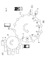
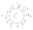
- Figs. 1 and 2 are diagrams illustrating the printing methods by using a plate-type printing apparatus (A) and an ink-jet printing apparatus (B) which are independent from each other.
- the seamless can having a plate-printed image is conveyed by a conveying device 5 to the ink-jet printing apparatus (B) and is subjected to the ink-jet printing and to the finishing varnish coating (C).
- the ink-jet printing apparatus B
- the finishing varnish coating C
- Figs. 3 and 4 are diagrams illustrating printing methods by using a hybrid apparatus in which the plate-type printing and the ink-jet printing are conducted in the same apparatus.
- the seamless can mounted on a mandrel 4 is, first, subjected to the plate-type printing and, thereafter, to the ink-jet printing and the finishing varnish coating (C).
- Fig. 3 the seamless can mounted on a mandrel 4 is, first, subjected to the plate-type printing and, thereafter, to the ink-jet printing and the finishing varnish coating (C).
- the seamless can mounted on the mandrel 4 is, first, subjected to the ink-jet printing and, thereafter, to the plate-type printing and the finishing varnish coating (C).
- the positioning as designated at 6 in the drawings and the false baking as designated at 7 in the drawings there are employed the positioning as designated at 6 in the drawings and the false baking as designated at 7 in the drawings. The false baking and positioning will be described later.
- the printing can be conducted according to any order described above. From the standpoint of easy positioning and designing such as overlapped printing by the ink-jet printing, however, it is specifically preferred to conduct the plate-type printing first. In this case, as will be described later, it is desired to false-cure the image formed first on the seamless can to suppress the ink from spreading. This prevents the ink from blurring on the portions where the images are overlapping, and a vivid image can be obtained. Further, to print the image as desired, it is important to effect the positioning prior to conducting the next printing when the plate-type printing and the ink-jet printing are conducted either by using the separate printing apparatuses or by using the same printing apparatus. Therefore, a positioning mark is formed by the first printing.
- the positioning mark is detected prior to conducting the next printing, the seamless can is positioned by controlling the turn of the mandrel mounting the seamless can, and the desired image is printed maintaining good reproducibility.
- the positioning mark may be formed at a plurality of places not at one place only. Instead of forming a special positioning mark, further, a portion of the printed image may be used as a mark for positioning, as a matter of course.
- the plate-type printing employed for printing the seamless cans of the present invention may be the printing system such as relief printing or lithography that has heretofore been employed for printing the seamless cans and, specifically preferably, the offset printing.
- the offset printing consists of feeding printing inks from ink feed units 1 to printing plates such as relief plates (not shown) on plate cylinders 2 and transferring the inks on the dots of the printing plates and on the image portion onto a blanket 3.
- the inks of all colors transferred onto the blanket 3 are further transferred onto the seamless cans mounted on mandrels 4 to thereby obtain the seamless cans printed by the plate-type printing.
- the inks are false-cured by false baking prior to conducting the ink-jet printing. This prevents the occurrence of blurring on the portions where the ink-jet printing overlaps the image.
- the image printed by the print-type printing forms, on a portion of it, a can-positioning mark for conducting the ink-jet printing. Specifically, it is desired that the mark is formed at a position that is concealed in the double-seamed portion after the step of double-seaming the can and the lid together.
- the printing inks used for the plate-type printing of the present invention may be the printing inks that have heretofore been used for printing the seamless cans and, specifically, the inks of the heat-drying type (solvent type).
- solvent type the inks of the heat-drying type
- the ink-jet printing employed for printing the seamless cans of the present invention may be the printing system that has heretofore been employed for printing the seamless cans.
- the ink-jet printing consists of injecting the droplets of inks from ink-jet heads 10 corresponding to the inks of white (W), yellow (Y), magenta (M), cyan (C) and black (K) so as to print an image on the seamless cans mounted on the mandrels 4.
- Arrangement of the ink-jet heads of these colors is not limited to an example that is shown but may be in any order.
- Figs. 5 to 8 are diagrams illustrating the timings for false baking in the ink-jet printing apparatus (B).
- the preferred timings for false baking designated at 7 in the drawings differ depending upon the image to be printed and the kinds of the inks used for the ink-jet printing. As shown in Figs.
- the inks are false-cured (i) after the feed of inks of all colors ( Fig. 5 ), (ii) immediately after the feed of each ink ( Fig. 6 ), (iii) after the feed of each ink but before the feed of the next ink ( Fig. 7 ), or (iv) two times immediately after the feed of the white ink and after the feed of inks of all colors ( Fig. 8 ).
- the plate-type printing is conducted first, and the ink-jet printing is conducted after the image printed by the plate-type printing is false-cured.
- the timings for false-curing the ink-jet printing are the same as in the cases of Figs. 5 to 8 . That is, the inks for ink-j et printing may be false-baked at any timings of (i) to (iv). From the economic standpoint, however, it is desired that the false-curing is conducted at the timings of (i) above. Further, as will be described later, when no white coating is formed on the seamless can, it is desired to solidly form a white layer all over the surface by the white-ink-jet printing in order to vividly form the image by ink-jet.
- the printing inks used for the ink-jet printing of the invention there can be used heat-drying inks, heat-curing inks, ultraviolet ray-curing inks or electron ray-curing inks that have heretofore been used for ink-jet-printing the seamless cans.
- the heat-drying inks are preferred from such a standpoint that the facility for baking is inexpensive.
- the heat-drying inks include those of the aqueous type, oil type and solvent type. Among them, the solvent types are preferred since the time needed for the curing is short.
- the system of the heads used for the ink-jet printing further, there have been known electrostatic system, piezo system, bubble-jet system and the like system which can be used in the present invention without limitation.
- the images are formed by the plate-type printing and the ink-jet printing and, thereafter, the finishing varnish is applied as designated at (C) in Figs. 1 to 4 .
- the present invention has an important feature in that the images formed by the plate-type printing and the ink-jet printing are both covered with the finishing varnish. This assures excellent adhesion of the printed images as well as scratch resistance of the printed seamless cans when the printed seamless cans are subjected to such workings as retort-sterilization and double-seaming or when they are rubbed by each other during the transit.
- finishing varnish used for producing the printed seamless cans of the invention there can be used a transparent coating material that has heretofore been used as a top coating of the printed seamless cans and, particularly preferably, coating material of the heat-curing type.
- the finishing varnish has been applied, when the heat-curing ink is used for forming images by the plate-type printing and the ink-jet printing simultaneously with the baking of the finishing varnish, the image formed by the ink-jet printing is baked to thereby produce the printed seamless cans of the present invention.
- the seamless cans that are to be printed are those seamless cans made from various surface-treated steel plates such as tin-free steel sheets (TFS), steel sheets plated with tin or the like, light metal sheets such as of aluminum, or resin-coated metal sheets comprising the above metal sheets coated with a thermoplastic resin such as polyester resin, that are formed through conventional means such as draw/redraw working, bend-stretch working (stretching) based on the draw/redrawing, bend-stretch/ironing based on the draw/redrawing, draw/ironing, or impact-working of a light metal sheet.
- TFS tin-free steel sheets
- light metal sheets such as of aluminum
- resin-coated metal sheets comprising the above metal sheets coated with a thermoplastic resin such as polyester resin
- a white coating on the outer surface of the seamless can since it conceals the ground color of the metal sheet and enables the image to be vividly printed. It is further desired to form an anchor coating on the white coating or on the outer surface of the seamless can when no white coating is formed thereon.
- the anchor coating Upon forming the anchor coating, the image formed by the ink-jet printing is firmly fixed and adheres more closely. The anchor coating, further, reduces the blurring of the ink that is jetted.
- the anchor coating can be formed by a known method; i.e., applying a coating solution obtained by dispersing or dissolving a heat-curable, ultraviolet ray-curable or electron ray-curable transparent polyester resin, acrylic resin, epoxy resin or urethane resin in a predetermined solvent, drying the thus formed coating, and curing the coating by heating, by the irradiation with ultraviolet rays or by the irradiation with electron rays.
- a method of heat-curing a heat-curable resin is preferred from the standpoint of a wide range of selection.
- the white coating can be similarly formed by adding a white pigment such as titanium dioxide to a coating solution comprising a resin exemplified above for forming the anchor coating.
- a preferred method comprises heat-curing a coating solution obtained by dispersing or dissolving the heat-curable resin in a solvent. It is desired that the thickness of the white coating is in a range of 0.1 to 10 ⁇ m and, specifically, 0.5 to 5 ⁇ m from the standpoint of concealing the ground color and that the thickness of the anchor coating is in a range of 0.1 to 5 ⁇ m and, specifically, 0.1 to 2 ⁇ m. The same effect can be obtained even by forming a white resin coating that contains a white pigment on the metal sheet instead of forming the white coating.
- Fig. 9 is a view illustrating a sectional structure of the body portion of the printed seamless can of the invention and in which a white coating 21 is formed on the outer surface of a can wall 20, and an anchor coating 22 is formed on the white coating 21.
- the anchor coating 22 there are formed inks 23a, 23b, 23c being transferred by the plate-type printing and inks 24a, 24b, 24c, 24d being injected by the ink-jet printing.
- the finishing varnish layer 25 is formed so as to completely cover both the inks 23 formed by the plate-type printing and the inks 24 formed by the ink-jet printing.
- the anchor coating 22 is formed on the outer surface of the can wall 20.
- the finishing varnish layer 25 is formed so as to completely cover both the inks 23 formed by the plate-type printing and the inks 24 formed by the ink-jet printing like in the case of Fig. 9 . In Fig. 10 , however, no white coating has been formed.
- the inks 24a, 24b, 24c and 24d of colors other than white are applied onto the white ink 26e that is solidly formed all over the surface by the ink-jet printing.
- the white ink 26e may not be solidly printed all over the surface but may be dot-printed.
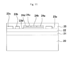
- the white coating 21 is formed on the outer surface of the can wall 20
- the anchor coating 22 is formed on the white coating 21
- inks 23a, 23b, 23c are formed on the anchor coating 22 being transferred by the plate-type printing
- inks 24a, 24b, 24c, 24d are formed being injected by the ink-jet printing
- the finishing varnish layer 25 is formed so as to completely cover both the inks 23 formed by the print-type printing and the inks 24 formed by the ink-jet printing in the same manner as in the case of Fig. 9 .
- the inks 29a, 24b, 24c, 24d are applied by the ink-jet printing onto the ink 23d that is applied by the plate-type printing forming a portion where the image formed by the plate-type printing and the image formed by the ink-jet printing are overlapping one upon the other.
- Figs. 12 and 13 are photographs showing embodiments of images printed on the body portions of the seamless cans of the invention.
- an image 31 is formed on nearly the whole surface of the can wall by the plate-type printing, the image 31 having a window portion 30 on where no image has been printed, and an image 32 is formed by the ink-jet printing on the window portion 30 where no image has been printed.
- the image 31 formed by the plate-type printing and having a window portion 30 on where no image has been formed serves as a fixed design
- a variable design 32 is formed by the ink-jet printing on the window portion 30 on where no image has been formed, making it possible to form seamless cans on which a variable design is printed.
- FIG. 13 shows the embodiment having a portion where an image is formed by the ink-jet printing on the image formed by the plate-type printing, i.e., the embodiment in which the image 31 is formed by the plate-type printing on the whole surface of the body portion of the seamless can and the image 32 is formed by the ink-jet printing on the image 31 that is formed by the plate-type printing.
- This embodiment makes it possible to provide seamless cans on which various designs are printed by varying the image 32 formed by the ink-jet printing.
- a seamless can was produced by blanking an aluminum alloy sheet JIS3004 of a thickness of 0.30 mm in a customary manner, drawing the blank to form a cup, redraw-ironing the cup, trimming an opening portion thereof, washing the inner and outer surfaces thereof with an acid solution by using a washing machine, and washing the cup with industrial water and with de-ionized water followed by drying.
- An epoxy-type anchor coating was applied onto the outer surface of the obtained seamless can and was baked.
- the seamless can was inserted in a mandrel of a hybrid printing apparatus shown in Fig. 3 , and was fixed therein by vacuum produced from the inside of the mandrel.
- the plate-type printing (offset printing), positioning, ink-jet printing, false-baking and application of finishing varnish were conducted accompanying the intermittent rotation of the apparatus shown in Fig. 3 , and the baking was conducted in an oven.
- the image formed by the ink-jet printing was false-baked at a timing shown in Fig. 8 .
- the image was printed in a design (1) as shown in Fig. 12 . No false-baking was conducted after the plate-type printing. Thereafter, the inner surface of the seamless can was coated and baked, and the opening portion of the seamless can was subjected to the necking and flanging to produce a 350-ml printed seamless can having a nominal can body diameter 211 and a nominal opening diameter 206. Details of the printing will be described below.
- the image of the design (1) shown in Fig. 12 was printed, and in which the image dot-printed by ink jet was not overlapping the image solidly printed all over the surface by the offset printing.
- the hybrid printing apparatus was as shown in Fig. 3 .
- a solvent-type ink that could be dried upon heating was solidly printed all over the outer surface of the can wall from the relief plate of resin via the blanket.
- a positioning mark 3 mm high and 10 mm wide was printed in black on the side of the opening portion. This portion was almost concealed in the double seamed portion of the lid after the content was filled.
- the positioning mark was detected by a camera, and the image formed by the plate-type printing was brought into agreement with the image formed by the ink-jet printing by turning the mandrel.
- a white ink (W-color) was solidly ink-jet-printed and was false-baked with the hot air of 100°C.
- dots were ink-jet-printed in order of yellow (Y-color), magenta (M-color), cyan (C-color) and black (K-color). Thereafter, the inks were baked at one time with the hot air of 100°C, the finishing varnish was applied thereon, and the baking was conducted at 200°C for one minute in an oven.
- the inks that were jet-printed were of the solvent type that could be dried by heating.
- the ink-jet head used for the ink-jet printing was of the single-head piezo type and was capable of printing the side wall of the seamless can over the whole height thereof.
- the seamless can was inserted and fixed in the mandrel so that the phases for printing Y-color, M-color, C-color and K-color were in agreement.
- the image to be printed had been programmed in a computer so as to be chromatically decomposed into Y-color, M-color, C-color and K-color, and reproduced with ink-jet-printed dots. Tables 1 and 2 show the specifications of the outer surface and the evaluated results.
- a printed seamless can was produced in the same manner as in Example 1 but without conducting the false-baking with the hot air after the W-color printing by ink jet.
- Tables 1 and 2 show the specifications of the outer surface and the evaluated results. The ink blurred slightly on a portion where the image was dot-printed by ink jet on the white image solidly printed all over the surface by ink jet.
- a printed seamless can was produced in the same manner as in Example 1 but without applying the anchor coating on the outer surface of the wall of the seamless can.
- Tables 1 and 2 show the specifications of the outer surface and the evaluated results.
- a printed seamless can was produced in the same manner as in Example 1 by applying a heat-curable base coating (white coating) containing a titanium oxide pigment onto the outer surface of the wall of the seamless can followed by baking and applying an anchor coating thereon followed by baking but conducting neither the W-color printing all over the surface by ink jet nor the baking thereof with the hot air.
- Tables 1 and 2 show the specifications of the outer surface and the evaluated results.
- a printed seamless can was produced in the same manner as in Example 4 but without applying and baking the finishing varnish.
- Tables 1 and 2 show the specifications of the outer surface and the evaluated results.
- a printed seamless can was produced in the same manner as in Example 1 but conducting the ink-jet printing by using an ink of the ultraviolet ray-curable type and employing a baking means based on the irradiation of ultraviolet rays.
- Tables 1 and 2 show the specifications of the outer surface and the evaluated results.
- a printed seamless can was produced in the same manner as in Example 5 but without conducting the false-baking with the irradiation of ultraviolet rays after the W-color printing by ink jet.
- Tables 1 and 2 show the specifications of the outer surface and the evaluated results. The ink blurred slightly on a portion where the image was dot-printed by ink jet on the white image solidly printed all over the surface by ink jet.
- a printed seamless can was produced in the same manner as in Example 5 but irradiating the ultraviolet rays every after the printing of each color by ink jet.
- the image formed by the ink-jet printing was false-baked at a timing shown in Fig. 7 .
- Tables 1 and 2 show the specifications of the outer surface and the evaluated results.
- the image dot-printed by ink jet was particularly vivid. The facility became bulky due to the provision of the ultraviolet ray irradiation apparatuses after the printing of each color by ink jet.
- a printed seamless can was produced in the same manner as in Example 5 by applying a heat-curable base coating (white coating) containing a titanium oxide pigment onto the outer surface of the wall of the seamless can followed by baking and applying an anchor coating thereon followed by baking but conducting neither the W-color solid printing all over the surface by ink jet nor the baking thereof with the ultraviolet rays.
- Tables 1 and 2 show the specifications of the outer surface and the evaluated results.
- a printed seamless can was produced in the same manner as in Example 1 but conducting the ink-jet printing by using inks of the electron ray-curable type and employing a baking means based on the irradiation of electron rays.
- Tables 1 and 2 show the specifications of the outer surface and the evaluated results.
- a printed seamless can was produced in the same manner as in Example 9 but without conducting the false-baking with the irradiation of electron rays after the W-color printing by ink jet.
- Tables 1 and 2 show the specifications of the outer surface and the evaluated results. The inks blurred slightly on a portion where the image was dot-printed by ink jet on the white image solidly printed all over the surface by ink jet.
- a printed seamless can was produced in the same manner as in Example 9 by applying a heat-curable base coating (white coating) containing a titanium oxide pigment onto the outer surface of the can wall followed by baking and applying an anchor coating thereon followed by baking but conducting neither the W-color solid printing all over the surface by ink jet nor the baking thereof by the irradiation with electron ray.
- Tables 1 and 2 show the specifications of the outer surface and the evaluated results.
- the image of the design (2) shown in Fig. 13 was printed, and in which the image printed (dot-printed) by ink jet was overlapping the image printed (solidly printed all over the surface) by the offset printing.
- a heat-curable base coating (white coating) containing a titanium oxide pigment was applied onto the outer surface of the side wall of the seamless can followed by baking and, thereafter, an anchor coating was applied thereon followed by baking.
- the seamless can was inserted and fixed in the mandrel of the apparatus shown in Fig. 3 .
- the plate-type printing (offset printing), false baking of the plate-printed image (treatment with the hot air of 100°C), positioning, ink-jet printing and false baking, and application of finishing varnish, were conducted accompanying the turn of the apparatus of Fig.
- a printed seamless can was produced in the same manner as in Example 12 but without false-baking the image formed by the plate-type printing.
- Tables 1 and 2 show the specifications of the outer surface and the evaluated results. The inks blurred slightly on a portion where the image was dot-printed by ink jet on the image formed by the plate-type printing.
- a printed seamless can was produced in the same manner as in Example 12 but conducting the ink-jet printing by using inks of the ultraviolet ray-curable type and employing a baking means based on the irradiation of ultraviolet rays.
- Tables 1 and 2 show the specifications of the outer surface and the evaluated results.
- a printed seamless can was produced in the same manner as in Example 14 but without false-baking the image formed by the plate-type printing.
- Tables 1 and 2 show the specifications of the outer surface and the evaluated results. The inks blurred slightly on a portion where the image was dot-printed by ink jet on the image formed by the plate-type printing.
- a printed seamless can was produced in the same manner as in Example 12 but conducting the ink-jet printing by using inks of the electron ray-curable type and employing a baking means based on the irradiation of electron rays.
- Tables 1 and 2 show the specifications of the outer surface and the evaluated results.
- a printed seamless can was produced in the same manner as in Example 16 but without false-baking the image formed by the plate-type printing.
- Tables 1 and 2 show the specifications of the outer surface and the evaluated results. The inks blurred slightly on a portion where the image was dot-printed by ink jet on the image formed by the plate-type printing.
- the apparatus shown in Fig. 1 was used as the printing apparatus.
- the image that was printed was the design (2) shown in Fig. 13 .
- the white coating and the anchor coating were formed on the outer surface of the seamless can like in Example 12. Thereafter, the seamless can was inserted and fixed in the mandrel of the plate-type printing apparatus shown in Fig. 1 , and the image was printed by offset printing (plate-type printing) by using solvent-type inks that could be dried by heating.
- the seamless can was conveyed to the ink-jet printing apparatus in a state where the bottom of the seamless can was sucked by vacuum from the outer surface side thereof and was fixed to the chuck, and was inserted in the mandrel of the ink-jet printing apparatus and was fixed thereto by vacuum.
- the hot air of 100°C was blown onto the side surface of the can wall to false-bake the printed image, and the mandrel was turned while detecting the positioning mark by using a camera so that the image to be formed by ink jet printing could be in agreement with the image formed by the plate-type printing.
- the procedure was the same as that in Example 12 to produce the printed seamless can.
- Tables 1 and 2 show the specifications of the outer surface and the evaluated results.
- the facility became bulky since the plate-type printing apparatus and the ink-jet printing apparatus were formed as separate apparatuses, and a conveyer apparatus was provided between them.
- the plate-type printing was conducted by using the printing apparatus shown in Fig. 3 followed by false baking and, thereafter, an image was printed in four colors by ink jet.
- the image of the same design as the design (1) shown in Fig. 12 was printed, the fixed design being solidly printed all over the surface by ink jet and the variable design being dot-printed thereon by ink jet all in one step.
- the procedure was the same as that in Example 4 to produce the printed seamless can.
- Tables 1 and 2 show the specifications of the outer surface and the evaluated results.
- the image solidly printed all over the surface by ink jet was dimming.
- a printed seamless can was produced in the same manner as in Comparative Example 2 but printing, in one step, an image of the same design as the design (2) shown in Fig. 13 , the fixed design being solidly printed all over the surface by ink jet and the variable design being dot-printed by ink jet.
- Tables 1 and 2 show the specifications of the outer surface and the evaluated results. The image solidly printed all over the surface by ink jet was dimming.
- a printed seamless can was produced in the same manner as in Comparative Example 2 but printing, in one step, an image of the same design as the design (1) shown in Fig. 12 by the offset printing (plate-type printing) only.
- the ink-jet printing was not conducted.
- Tables 1 and 2 show the specifications of the outer surface and the evaluated results.
- a printed seamless can was produced in the same manner as in Comparative Example 3 but printing an image of the same design as the design (2) shown in Fig. 13 by the offset printing (plate-type printing) only.
- the ink-jet printing was not conducted.
- Tables 1 and 2 show the specifications of the outer surface and the evaluated results.
- the seamless cans that were produced were evaluated for their images printed thereon with the eye into four steps.
- the evaluation was on the basis of excellent (O), good ( ⁇ ), fairly good ( ⁇ ) and defective ( ⁇ ), Evaluations O, ⁇ and ⁇ pertained to an allowable range. For the defective images, the reasons were added as described in Table 2.
- the printed seamless cans that were produced were evaluated for their luster on the printed surfaces with the eye into three steps.
- the evaluation was on the basis of good ( ⁇ ), fairly good ( ⁇ ) and defective ( ⁇ ). Evaluations ⁇ and ⁇ pertained to an allowable range.
- the printed seamless cans that were produced were subjected to the retort-treatment with steam heated at 130°C for 30 minutes. Thereafter, by using a cutter knife, six scratch lines were formed in each of the images of the offset-printed portion, ink-jet-printed portion and portion on where the ink-jet-printed portion overlapped the offset-printed portion maintaining a gap of 1 mm in the direction of height of the can and in the circumferential direction of the can to form a grid pattern consisting of 25 pieces.
- a cellophane tape (manufactured by Nichiban Co., registered trade name) was stuck thereto and was peeled off one time to evaluate the adhering property of the inks on the following basis of ( ⁇ ) when the peeling was less than 10%, ( ⁇ ) when the peeling was not less than 10% but was less than 50%, and ( ⁇ ) when the peeling was not less than 50%. Evaluations ⁇ and ⁇ pertained to an allowable range.
- the printed seamless cans that were produced were filled with tap water, double-seamed with lids, and were put in a carton (24-can carton) which was packed up.
- vibration corresponding to 1 G was imparted to the cans in the longitudinal and transverse directions for 30 minutes each, and the scratched states of the printed surfaces were observed with the eye and evaluated into three steps.
- the basis of evaluation was as follows, ⁇ and ⁇ being regarded to be in an allowable range:
- a scratch line was formed in the outer surfaces of the neck portions of the printed seamless cans that were produced along the whole circumference thereof.
- the printed seamless cans were subjected to the retort-treatment with steam heated at 130°C for 30 minutes, and were observed with the eye if the printed film was peeling at the scratched portion to thereby evaluate the adhering property at the worked portion.
- n 10 cans. The evaluation was on the basis of ( ⁇ ) when less than 10% of the cans developed peeling, ( ⁇ ) when more than 10% but less than 50% of the cans developed peeling, and ( ⁇ ) when more than 50% of the cans developed peeling. Evaluations ⁇ and ⁇ pertained to an allowable range.
- variable designs Without changing the fixed designs, the variable designs only were changed in the designs (1) and (2) shown in Figs. 12 and 13 , and the time required for changing the design was evaluated. The evaluation was on the basis of ⁇ (short time) and ⁇ (long time). ⁇ was when the facility became bulky. Evaluations ⁇ and ⁇ pertained to an allowable range.
- the printed seamless cans of the present invention excel in the reproducibility of density of the area solidly printed all over the surface and in the vividness of image and, further, excel in changing the design, and are suited for use as printed seamless cans that are desired to be produced in small lots having many kinds of designs. According to the method of producing printed seamless cans of the present invention, it is allowed to partly change the designs easily and in short periods of time making it possible to produce the printed seamless cans for containing beverages that are desired to be produced in small lots having many kinds of designs maintaining good productivity.
Landscapes
- Engineering & Computer Science (AREA)
- Manufacturing & Machinery (AREA)
- Mechanical Engineering (AREA)
- Details Of Rigid Or Semi-Rigid Containers (AREA)
- Application Of Or Painting With Fluid Materials (AREA)
- Printing Methods (AREA)
- Ink Jet (AREA)
- Ink Jet Recording Methods And Recording Media Thereof (AREA)
Applications Claiming Priority (2)
| Application Number | Priority Date | Filing Date | Title |
|---|---|---|---|
| JP2010234904A JP5724285B2 (ja) | 2010-10-19 | 2010-10-19 | 印刷シームレス缶及びその製造方法 |
| PCT/JP2011/073441 WO2012053406A1 (ja) | 2010-10-19 | 2011-10-12 | 印刷シームレス缶及びその製造方法 |
Publications (3)
| Publication Number | Publication Date |
|---|---|
| EP2631191A1 true EP2631191A1 (de) | 2013-08-28 |
| EP2631191A4 EP2631191A4 (de) | 2016-03-09 |
| EP2631191B1 EP2631191B1 (de) | 2018-08-29 |
Family
ID=45975123
Family Applications (1)
| Application Number | Title | Priority Date | Filing Date |
|---|---|---|---|
| EP11834246.8A Active EP2631191B1 (de) | 2010-10-19 | 2011-10-12 | Bedruckte nahtlose dose und verfahren zu ihrer herstellung |
Country Status (5)
| Country | Link |
|---|---|
| US (1) | US8899718B2 (de) |
| EP (1) | EP2631191B1 (de) |
| JP (1) | JP5724285B2 (de) |
| CN (1) | CN103328336B (de) |
| WO (1) | WO2012053406A1 (de) |
Cited By (3)
| Publication number | Priority date | Publication date | Assignee | Title |
|---|---|---|---|---|
| US20160221708A1 (en) * | 2013-10-25 | 2016-08-04 | Showa Aluminum Can Corporation | Can body manufacturing method, printing device, and beverage can |
| EP2909039B1 (de) | 2012-09-26 | 2017-12-20 | OCE-Technologies B.V. | Verfahren zur anwendung einer härtbaren flüssigkeit und vorrichtung zur durchführung des verfahrens |
| EP2858825B1 (de) * | 2012-06-08 | 2021-04-07 | Ball Beverage Packaging Europe Limited | Verfahren zum bedrucken einer zylindrischen druckoberfläche einer getränkedose und bedruckte getränkedose |
Families Citing this family (52)
| Publication number | Priority date | Publication date | Assignee | Title |
|---|---|---|---|---|
| DE102011119169A1 (de) * | 2011-11-23 | 2013-05-23 | Khs Gmbh | Vorrichtung zum Aufbringen vonAusstattungen auf Behälter |
| WO2013115302A1 (ja) * | 2012-02-03 | 2013-08-08 | 東洋製罐グループホールディングス株式会社 | インクジェット印刷用インク、印刷円筒形容器及びその製造方法 |
| BR102012016393A2 (pt) | 2012-07-02 | 2015-04-07 | Rexam Beverage Can South America S A | Dispositivo de impressão em latas, processo de impressão em latas, lata impressa e blanqueta |
| WO2014008544A1 (en) * | 2012-07-10 | 2014-01-16 | Amcor Limited | An apparatus and process |
| JP6111571B2 (ja) * | 2012-09-06 | 2017-04-12 | 東洋製罐株式会社 | インクジェット印刷装置及び円筒形状容器への印刷方法 |
| JP6234023B2 (ja) * | 2012-11-17 | 2017-11-22 | 株式会社ミマキエンジニアリング | 立体物上印刷システムおよび立体物上印刷用プログラム |
| CN105377566B (zh) | 2013-06-11 | 2018-08-10 | 鲍尔公司 | 使用软质光聚合物板的印刷工艺 |
| US9555616B2 (en) | 2013-06-11 | 2017-01-31 | Ball Corporation | Variable printing process using soft secondary plates and specialty inks |
| JP6285253B2 (ja) * | 2014-04-01 | 2018-02-28 | 昭和アルミニウム缶株式会社 | 印刷装置、および、画像が形成された缶体の製造方法 |
| JP2016000385A (ja) * | 2014-06-12 | 2016-01-07 | 武内プレス工業株式会社 | 鏡面光沢を有する金属容器の製造方法及びこの製法で造られた金属容器 |
| JP6393548B2 (ja) * | 2014-07-31 | 2018-09-19 | アイマー・プランニング株式会社 | 缶印刷装置 |
| US10086602B2 (en) | 2014-11-10 | 2018-10-02 | Rexam Beverage Can South America | Method and apparatus for printing metallic beverage container bodies |
| US20160136968A1 (en) * | 2014-11-13 | 2016-05-19 | The Procter & Gamble Company | Apparatus and Method for Depositing a Substance on and/or Decorating Articles |
| EP3028856B2 (de) | 2014-12-04 | 2023-07-26 | Ball Beverage Packaging Europe Limited | Druckvorrichtung |
| JP6755077B2 (ja) * | 2015-04-10 | 2020-09-16 | 昭和アルミニウム缶株式会社 | 印刷装置 |
| EP3756891B1 (de) | 2015-08-05 | 2023-03-01 | ALTEMIRA Co., Ltd. | Druckvorrichtung |
| JP6637266B2 (ja) * | 2015-08-05 | 2020-01-29 | 昭和アルミニウム缶株式会社 | 印刷装置 |
| JP6647815B2 (ja) * | 2015-08-05 | 2020-02-14 | 昭和アルミニウム缶株式会社 | 印刷装置 |
| JP6581840B2 (ja) * | 2015-08-11 | 2019-09-25 | 昭和アルミニウム缶株式会社 | 飲料用缶、飲料用缶の製造方法および画像形成システム |
| US10549921B2 (en) | 2016-05-19 | 2020-02-04 | Rexam Beverage Can Company | Beverage container body decorator inspection apparatus |
| JP6877097B2 (ja) * | 2016-06-28 | 2021-05-26 | 昭和アルミニウム缶株式会社 | 印刷装置、飲料用缶の製造方法 |
| DE102016212521A1 (de) * | 2016-07-08 | 2018-01-11 | Krones Ag | Verfahren und Vorrichtung zum mehrfarbigen Tintenstrahldruck auf Behälter |
| US10976263B2 (en) | 2016-07-20 | 2021-04-13 | Ball Corporation | System and method for aligning an inker of a decorator |
| US11034145B2 (en) | 2016-07-20 | 2021-06-15 | Ball Corporation | System and method for monitoring and adjusting a decorator for containers |
| EP3496952B1 (de) * | 2016-08-10 | 2024-05-29 | Ball Corporation | Verfahren und vorrichtung zum dekorieren eines metallischen behälters durch digitaldruck auf ein transfertuch |
| US10739705B2 (en) | 2016-08-10 | 2020-08-11 | Ball Corporation | Method and apparatus of decorating a metallic container by digital printing to a transfer blanket |
| JP7013129B2 (ja) * | 2017-01-31 | 2022-01-31 | 昭和アルミニウム缶株式会社 | 飲料用缶の製造方法、印刷システム、装置、プログラム、および、飲料用缶 |
| CN110546007B (zh) | 2017-04-24 | 2022-01-04 | 佛蒙特移印机械公司 | 独立印刷数据检测 |
| CN107415457A (zh) * | 2017-05-18 | 2017-12-01 | 山东双源印铁制罐有限公司 | 一种印刷洗铁自动烘干机 |
| JP7013161B2 (ja) | 2017-07-31 | 2022-01-31 | 昭和アルミニウム缶株式会社 | 飲料用缶の製造方法 |
| PL234264B1 (pl) * | 2017-08-18 | 2020-01-31 | Can Pack Spolka Akcyjna | Sposób i urządzenie do wykonania nadruku na puszkach |
| CA3075092C (en) | 2017-09-19 | 2022-08-23 | Ball Corporation | Container decoration apparatus and method |
| US10710377B2 (en) * | 2017-09-22 | 2020-07-14 | Xerox Corporation | System and method for producing an image on an article |
| JP2019108138A (ja) * | 2017-12-15 | 2019-07-04 | 昭和アルミニウム缶株式会社 | 飲料用缶、飲料缶、および、飲料用缶の製造方法 |
| JP7270805B2 (ja) * | 2017-12-27 | 2023-05-10 | アルテミラ株式会社 | 印刷装置 |
| JP7382130B2 (ja) * | 2018-01-09 | 2023-11-16 | アルテミラ株式会社 | 飲料用缶の製造方法、飲料用缶、および、飲料缶 |
| CN111867840B (zh) * | 2018-02-09 | 2022-05-17 | 鲍尔公司 | 通过向转印毡上进行数字印刷来装饰金属容器的方法和设备 |
| JP2019171659A (ja) * | 2018-03-28 | 2019-10-10 | 大和製罐株式会社 | 容器、容器の製造方法及び印刷装置 |
| JP2019209612A (ja) * | 2018-06-05 | 2019-12-12 | 東洋製罐株式会社 | 連続印刷システム |
| JP7171246B2 (ja) * | 2018-06-05 | 2022-11-15 | 東洋製罐株式会社 | 印刷缶の製造方法、及び印刷缶 |
| JP7149768B2 (ja) * | 2018-08-20 | 2022-10-07 | 株式会社Screenホールディングス | 印刷方法および印刷装置 |
| JP7406690B2 (ja) * | 2018-09-26 | 2023-12-28 | 東洋製罐株式会社 | 筒状容器の製造方法及び筒状容器 |
| JP7300261B2 (ja) * | 2018-11-12 | 2023-06-29 | アルテミラ株式会社 | 印刷システムおよび缶体の製造方法 |
| JP2020083391A (ja) * | 2018-11-27 | 2020-06-04 | 東洋製罐株式会社 | 加飾システムおよび加飾方法、並びに筒形状容器 |
| CN109677109B (zh) * | 2019-02-28 | 2020-02-14 | 广州泉源化学科技有限公司 | 一种新型多功能无缝罐印刷装置 |
| US20220371782A1 (en) * | 2019-09-30 | 2022-11-24 | Toyo Seikan Co., Ltd. | Method for Manufacturing Object to be Printed and Object to be Printed |
| JP7419796B2 (ja) * | 2019-12-23 | 2024-01-23 | 東洋製罐株式会社 | 基体の製造方法および容器 |
| JP7393242B2 (ja) * | 2020-02-20 | 2023-12-06 | アルテミラ株式会社 | 缶体印刷システム、および缶体印刷装置 |
| JP2021160218A (ja) | 2020-03-31 | 2021-10-11 | 東洋製罐株式会社 | 印刷物の製造方法、印刷装置及び印刷缶 |
| CN111619215B (zh) * | 2020-06-05 | 2022-05-31 | 成都优威易比应用技术有限公司 | 柔性基材eb固化系统和方法以及制备功能复合膜的方法 |
| WO2022269456A1 (en) * | 2021-06-22 | 2022-12-29 | Sacmi Imola S.C. | Apparatus for printing closure bodies of containers |
| US11857847B2 (en) * | 2022-02-02 | 2024-01-02 | Acushnet Company | Golf ball having overlap markings |
Family Cites Families (21)
| Publication number | Priority date | Publication date | Assignee | Title |
|---|---|---|---|---|
| US3817209A (en) * | 1973-02-16 | 1974-06-18 | Vlaanderen Container Machine | Gravure coating |
| JPS5743893A (en) * | 1980-08-28 | 1982-03-12 | Nippon Alum Mfg Co Ltd:The | Printing on metal barrel-shaped container |
| JPH0741718B2 (ja) * | 1985-10-01 | 1995-05-10 | 太陽鉄工株式会社 | 印刷機における回転部材の原点位置合わせ方法 |
| JP2555697B2 (ja) * | 1988-06-15 | 1996-11-20 | 東洋製罐株式会社 | 薄肉化絞り成形印刷缶及びその製法 |
| JPH10291539A (ja) * | 1997-02-19 | 1998-11-04 | Kanji Yamada | 包装用容器 |
| JP3713966B2 (ja) * | 1998-07-24 | 2005-11-09 | 東洋製罐株式会社 | 絞り成形体への事前印刷法 |
| JP2002205743A (ja) * | 2001-01-09 | 2002-07-23 | Neo Puraton:Kk | 缶入り飲料、缶入り飲料自動販売機、及び缶入り飲料を用いた広告方法 |
| JP2003084698A (ja) * | 2001-09-10 | 2003-03-19 | Toppan Printing Co Ltd | 広告付き容器包装体およびその製造方法及び広告付き容器包装体の広告決定方法およびそのシステム |
| DE10226500B4 (de) * | 2002-06-14 | 2010-04-22 | Ball Packaging Europe Holding Gmbh & Co. Kg | Vorrichtung zur Oberflächenbearbeitung von Teilen |
| JP2004042464A (ja) | 2002-07-12 | 2004-02-12 | Toyo Ink Mfg Co Ltd | 立体物への印刷方法 |
| JP2004098309A (ja) | 2002-09-05 | 2004-04-02 | Toyo Ink Mfg Co Ltd | 印刷方法および印刷物 |
| JP2005165647A (ja) * | 2003-12-02 | 2005-06-23 | Fuji Photo Film Co Ltd | 自動販売機 |
| JP4590241B2 (ja) * | 2004-09-29 | 2010-12-01 | 武内プレス工業株式会社 | 金属容器の製造方法及び金属容器 |
| JP2006224586A (ja) * | 2005-02-21 | 2006-08-31 | Hokkai Can Co Ltd | シームレス缶体 |
| JP4840035B2 (ja) | 2006-09-06 | 2011-12-21 | 東洋製罐株式会社 | シームレス缶の印刷方法 |
| JP5040250B2 (ja) * | 2006-10-10 | 2012-10-03 | 沖電気工業株式会社 | 通帳印刷システム及び該システムにより印刷される通帳 |
| JP2009149037A (ja) * | 2007-12-21 | 2009-07-09 | Tohoku Ricoh Co Ltd | インクジェット印刷装置におけるコーティング装置 |
| JP5218744B2 (ja) * | 2008-03-28 | 2013-06-26 | 東洋製罐株式会社 | 識別コード付き食品容器及び食品容器の識別コード形成方法 |
| EP2322445B1 (de) * | 2008-08-04 | 2017-10-04 | Toyo Seikan Kaisha, Ltd. | Dekorativer dosenkörper und herstellungsverfahren dafür |
| CN101708673B (zh) * | 2009-09-23 | 2012-05-23 | 太平洋制罐(北京)有限公司 | 铝制两片易拉罐的印刷底片设计方法 |
| US20110165542A1 (en) * | 2010-01-07 | 2011-07-07 | Fairfield University | Multi-parameter, customizable simulation building system for clinical scenarios for educating and training nurses and other health care professionals |
-
2010
- 2010-10-19 JP JP2010234904A patent/JP5724285B2/ja active Active
-
2011
- 2011-10-12 US US13/825,244 patent/US8899718B2/en active Active
- 2011-10-12 WO PCT/JP2011/073441 patent/WO2012053406A1/ja active Application Filing
- 2011-10-12 EP EP11834246.8A patent/EP2631191B1/de active Active
- 2011-10-12 CN CN201180050087.8A patent/CN103328336B/zh active Active
Cited By (6)
| Publication number | Priority date | Publication date | Assignee | Title |
|---|---|---|---|---|
| EP2858825B1 (de) * | 2012-06-08 | 2021-04-07 | Ball Beverage Packaging Europe Limited | Verfahren zum bedrucken einer zylindrischen druckoberfläche einer getränkedose und bedruckte getränkedose |
| US11192390B2 (en) | 2012-06-08 | 2021-12-07 | Ball Beverage Packaging Europe Limited | Method for printing a cylindrical printing surface of a beverage can, and printed beverage can |
| EP2909039B1 (de) | 2012-09-26 | 2017-12-20 | OCE-Technologies B.V. | Verfahren zur anwendung einer härtbaren flüssigkeit und vorrichtung zur durchführung des verfahrens |
| US20160221708A1 (en) * | 2013-10-25 | 2016-08-04 | Showa Aluminum Can Corporation | Can body manufacturing method, printing device, and beverage can |
| EP3061699A4 (de) * | 2013-10-25 | 2017-08-09 | Showa Aluminum Can Corporation | Dosenkörperherstellungsverfahren, druckvorrichtung und getränkedose |
| US10442564B2 (en) * | 2013-10-25 | 2019-10-15 | Showa Aluminum Can Corporation | Can body manufacturing method, printing device, and beverage can |
Also Published As
| Publication number | Publication date |
|---|---|
| JP5724285B2 (ja) | 2015-05-27 |
| WO2012053406A1 (ja) | 2012-04-26 |
| JP2012086870A (ja) | 2012-05-10 |
| CN103328336A (zh) | 2013-09-25 |
| CN103328336B (zh) | 2015-06-03 |
| US8899718B2 (en) | 2014-12-02 |
| US20130176358A1 (en) | 2013-07-11 |
| EP2631191B1 (de) | 2018-08-29 |
| EP2631191A4 (de) | 2016-03-09 |
Similar Documents
| Publication | Publication Date | Title |
|---|---|---|
| EP2631191B1 (de) | Bedruckte nahtlose dose und verfahren zu ihrer herstellung | |
| EP2810994B1 (de) | Tinte für tintenstrahldruck, bedruckter zylindrischer behälter und herstellungsverfahren dafür | |
| EP2703305A1 (de) | Tintenstrahldrucker und verfahren zum bedrucken einer nahtlosen dose damit | |
| US9259913B2 (en) | Apparatus and method for orienting a beverage container end closure and applying indicia in a predetermined location | |
| JP6111571B2 (ja) | インクジェット印刷装置及び円筒形状容器への印刷方法 | |
| CN111902284B (zh) | 容器、容器的制造方法以及印刷装置 | |
| CN105829209B (zh) | 容器用印制膜及其制造方法 | |
| JP6314468B2 (ja) | 印刷缶及びその製造方法 | |
| WO2011092927A1 (ja) | 容器用インキジェット印刷フィルム、その製造方法及び製造装置 | |
| JP2018012250A (ja) | 表と裏とが異なった図柄の印刷面を有する三方シール袋及びその製法。 | |
| JP2022183006A (ja) | 容器上にレリーフ状の印刷画像を作り出す方法 | |
| JP2019108138A (ja) | 飲料用缶、飲料缶、および、飲料用缶の製造方法 | |
| JP2006224585A (ja) | シームレス缶体 | |
| JP2006224584A (ja) | シームレス缶体 | |
| JP2020083391A (ja) | 加飾システムおよび加飾方法、並びに筒形状容器 | |
| JP6140942B2 (ja) | 印刷が施されたチューブ状積層容器及びその製造方法 | |
| JP2006224586A (ja) | シームレス缶体 |
Legal Events
| Date | Code | Title | Description |
|---|---|---|---|
| PUAI | Public reference made under article 153(3) epc to a published international application that has entered the european phase |
Free format text: ORIGINAL CODE: 0009012 |
|
| 17P | Request for examination filed |
Effective date: 20130315 |
|
| AK | Designated contracting states |
Kind code of ref document: A1 Designated state(s): AL AT BE BG CH CY CZ DE DK EE ES FI FR GB GR HR HU IE IS IT LI LT LU LV MC MK MT NL NO PL PT RO RS SE SI SK SM TR |
|
| DAX | Request for extension of the european patent (deleted) | ||
| RA4 | Supplementary search report drawn up and despatched (corrected) |
Effective date: 20160208 |
|
| RIC1 | Information provided on ipc code assigned before grant |
Ipc: B41F 19/00 20060101AFI20160202BHEP Ipc: B41M 5/00 20060101ALI20160202BHEP Ipc: B41J 2/01 20060101ALI20160202BHEP Ipc: B41M 1/18 20060101ALI20160202BHEP Ipc: B41M 7/02 20060101ALI20160202BHEP Ipc: B41J 3/42 20060101ALI20160202BHEP Ipc: B41M 1/06 20060101ALI20160202BHEP Ipc: B41J 3/44 20060101ALI20160202BHEP Ipc: B41M 1/40 20060101ALI20160202BHEP Ipc: B41F 17/22 20060101ALI20160202BHEP Ipc: B41M 1/04 20060101ALI20160202BHEP Ipc: B41F 23/04 20060101ALI20160202BHEP |
|
| REG | Reference to a national code |
Ref country code: DE Ref legal event code: R079 Ref document number: 602011051605 Country of ref document: DE Free format text: PREVIOUS MAIN CLASS: B65D0025200000 Ipc: B41F0019000000 |
|
| GRAP | Despatch of communication of intention to grant a patent |
Free format text: ORIGINAL CODE: EPIDOSNIGR1 |
|
| STAA | Information on the status of an ep patent application or granted ep patent |
Free format text: STATUS: GRANT OF PATENT IS INTENDED |
|
| RIC1 | Information provided on ipc code assigned before grant |
Ipc: B41M 1/04 20060101ALI20180315BHEP Ipc: B41F 23/04 20060101ALI20180315BHEP Ipc: B41M 1/18 20060101ALI20180315BHEP Ipc: B41M 7/02 20060101ALI20180315BHEP Ipc: B41M 1/06 20060101ALI20180315BHEP Ipc: B41F 19/00 20060101AFI20180315BHEP Ipc: B41J 2/01 20060101ALI20180315BHEP Ipc: B41M 1/40 20060101ALI20180315BHEP Ipc: B41M 5/00 20060101ALI20180315BHEP Ipc: B41F 17/22 20060101ALI20180315BHEP Ipc: B41J 3/42 20060101ALI20180315BHEP Ipc: B41J 3/44 20060101ALI20180315BHEP |
|
| INTG | Intention to grant announced |
Effective date: 20180418 |
|
| GRAS | Grant fee paid |
Free format text: ORIGINAL CODE: EPIDOSNIGR3 |
|
| GRAA | (expected) grant |
Free format text: ORIGINAL CODE: 0009210 |
|
| STAA | Information on the status of an ep patent application or granted ep patent |
Free format text: STATUS: THE PATENT HAS BEEN GRANTED |
|
| AK | Designated contracting states |
Kind code of ref document: B1 Designated state(s): AL AT BE BG CH CY CZ DE DK EE ES FI FR GB GR HR HU IE IS IT LI LT LU LV MC MK MT NL NO PL PT RO RS SE SI SK SM TR |
|
| REG | Reference to a national code |
Ref country code: GB Ref legal event code: FG4D |
|
| REG | Reference to a national code |
Ref country code: CH Ref legal event code: EP |
|
| REG | Reference to a national code |
Ref country code: AT Ref legal event code: REF Ref document number: 1034658 Country of ref document: AT Kind code of ref document: T Effective date: 20180915 |
|
| REG | Reference to a national code |
Ref country code: IE Ref legal event code: FG4D |
|
| REG | Reference to a national code |
Ref country code: DE Ref legal event code: R096 Ref document number: 602011051605 Country of ref document: DE |
|
| REG | Reference to a national code |
Ref country code: NL Ref legal event code: MP Effective date: 20180829 |
|
| REG | Reference to a national code |
Ref country code: LT Ref legal event code: MG4D |
|
| PG25 | Lapsed in a contracting state [announced via postgrant information from national office to epo] |
Ref country code: NL Free format text: LAPSE BECAUSE OF FAILURE TO SUBMIT A TRANSLATION OF THE DESCRIPTION OR TO PAY THE FEE WITHIN THE PRESCRIBED TIME-LIMIT Effective date: 20180829 Ref country code: BG Free format text: LAPSE BECAUSE OF FAILURE TO SUBMIT A TRANSLATION OF THE DESCRIPTION OR TO PAY THE FEE WITHIN THE PRESCRIBED TIME-LIMIT Effective date: 20181129 Ref country code: NO Free format text: LAPSE BECAUSE OF FAILURE TO SUBMIT A TRANSLATION OF THE DESCRIPTION OR TO PAY THE FEE WITHIN THE PRESCRIBED TIME-LIMIT Effective date: 20181129 Ref country code: RS Free format text: LAPSE BECAUSE OF FAILURE TO SUBMIT A TRANSLATION OF THE DESCRIPTION OR TO PAY THE FEE WITHIN THE PRESCRIBED TIME-LIMIT Effective date: 20180829 Ref country code: FI Free format text: LAPSE BECAUSE OF FAILURE TO SUBMIT A TRANSLATION OF THE DESCRIPTION OR TO PAY THE FEE WITHIN THE PRESCRIBED TIME-LIMIT Effective date: 20180829 Ref country code: GR Free format text: LAPSE BECAUSE OF FAILURE TO SUBMIT A TRANSLATION OF THE DESCRIPTION OR TO PAY THE FEE WITHIN THE PRESCRIBED TIME-LIMIT Effective date: 20181130 Ref country code: IS Free format text: LAPSE BECAUSE OF FAILURE TO SUBMIT A TRANSLATION OF THE DESCRIPTION OR TO PAY THE FEE WITHIN THE PRESCRIBED TIME-LIMIT Effective date: 20181229 Ref country code: LT Free format text: LAPSE BECAUSE OF FAILURE TO SUBMIT A TRANSLATION OF THE DESCRIPTION OR TO PAY THE FEE WITHIN THE PRESCRIBED TIME-LIMIT Effective date: 20180829 Ref country code: SE Free format text: LAPSE BECAUSE OF FAILURE TO SUBMIT A TRANSLATION OF THE DESCRIPTION OR TO PAY THE FEE WITHIN THE PRESCRIBED TIME-LIMIT Effective date: 20180829 |
|
| REG | Reference to a national code |
Ref country code: AT Ref legal event code: MK05 Ref document number: 1034658 Country of ref document: AT Kind code of ref document: T Effective date: 20180829 |
|
| PG25 | Lapsed in a contracting state [announced via postgrant information from national office to epo] |
Ref country code: LV Free format text: LAPSE BECAUSE OF FAILURE TO SUBMIT A TRANSLATION OF THE DESCRIPTION OR TO PAY THE FEE WITHIN THE PRESCRIBED TIME-LIMIT Effective date: 20180829 Ref country code: HR Free format text: LAPSE BECAUSE OF FAILURE TO SUBMIT A TRANSLATION OF THE DESCRIPTION OR TO PAY THE FEE WITHIN THE PRESCRIBED TIME-LIMIT Effective date: 20180829 Ref country code: AL Free format text: LAPSE BECAUSE OF FAILURE TO SUBMIT A TRANSLATION OF THE DESCRIPTION OR TO PAY THE FEE WITHIN THE PRESCRIBED TIME-LIMIT Effective date: 20180829 |
|
| PG25 | Lapsed in a contracting state [announced via postgrant information from national office to epo] |
Ref country code: IT Free format text: LAPSE BECAUSE OF FAILURE TO SUBMIT A TRANSLATION OF THE DESCRIPTION OR TO PAY THE FEE WITHIN THE PRESCRIBED TIME-LIMIT Effective date: 20180829 Ref country code: CZ Free format text: LAPSE BECAUSE OF FAILURE TO SUBMIT A TRANSLATION OF THE DESCRIPTION OR TO PAY THE FEE WITHIN THE PRESCRIBED TIME-LIMIT Effective date: 20180829 Ref country code: RO Free format text: LAPSE BECAUSE OF FAILURE TO SUBMIT A TRANSLATION OF THE DESCRIPTION OR TO PAY THE FEE WITHIN THE PRESCRIBED TIME-LIMIT Effective date: 20180829 Ref country code: ES Free format text: LAPSE BECAUSE OF FAILURE TO SUBMIT A TRANSLATION OF THE DESCRIPTION OR TO PAY THE FEE WITHIN THE PRESCRIBED TIME-LIMIT Effective date: 20180829 Ref country code: PL Free format text: LAPSE BECAUSE OF FAILURE TO SUBMIT A TRANSLATION OF THE DESCRIPTION OR TO PAY THE FEE WITHIN THE PRESCRIBED TIME-LIMIT Effective date: 20180829 Ref country code: EE Free format text: LAPSE BECAUSE OF FAILURE TO SUBMIT A TRANSLATION OF THE DESCRIPTION OR TO PAY THE FEE WITHIN THE PRESCRIBED TIME-LIMIT Effective date: 20180829 Ref country code: AT Free format text: LAPSE BECAUSE OF FAILURE TO SUBMIT A TRANSLATION OF THE DESCRIPTION OR TO PAY THE FEE WITHIN THE PRESCRIBED TIME-LIMIT Effective date: 20180829 |
|
| PG25 | Lapsed in a contracting state [announced via postgrant information from national office to epo] |
Ref country code: SK Free format text: LAPSE BECAUSE OF FAILURE TO SUBMIT A TRANSLATION OF THE DESCRIPTION OR TO PAY THE FEE WITHIN THE PRESCRIBED TIME-LIMIT Effective date: 20180829 Ref country code: DK Free format text: LAPSE BECAUSE OF FAILURE TO SUBMIT A TRANSLATION OF THE DESCRIPTION OR TO PAY THE FEE WITHIN THE PRESCRIBED TIME-LIMIT Effective date: 20180829 Ref country code: SM Free format text: LAPSE BECAUSE OF FAILURE TO SUBMIT A TRANSLATION OF THE DESCRIPTION OR TO PAY THE FEE WITHIN THE PRESCRIBED TIME-LIMIT Effective date: 20180829 |
|
| REG | Reference to a national code |
Ref country code: DE Ref legal event code: R097 Ref document number: 602011051605 Country of ref document: DE Ref country code: CH Ref legal event code: PL |
|
| REG | Reference to a national code |
Ref country code: BE Ref legal event code: MM Effective date: 20181031 |
|
| PG25 | Lapsed in a contracting state [announced via postgrant information from national office to epo] |
Ref country code: MC Free format text: LAPSE BECAUSE OF FAILURE TO SUBMIT A TRANSLATION OF THE DESCRIPTION OR TO PAY THE FEE WITHIN THE PRESCRIBED TIME-LIMIT Effective date: 20180829 Ref country code: LU Free format text: LAPSE BECAUSE OF NON-PAYMENT OF DUE FEES Effective date: 20181012 |
|
| PLBE | No opposition filed within time limit |
Free format text: ORIGINAL CODE: 0009261 |
|
| STAA | Information on the status of an ep patent application or granted ep patent |
Free format text: STATUS: NO OPPOSITION FILED WITHIN TIME LIMIT |
|
| REG | Reference to a national code |
Ref country code: IE Ref legal event code: MM4A |
|
| 26N | No opposition filed |
Effective date: 20190531 |
|
| PG25 | Lapsed in a contracting state [announced via postgrant information from national office to epo] |
Ref country code: LI Free format text: LAPSE BECAUSE OF NON-PAYMENT OF DUE FEES Effective date: 20181031 Ref country code: CH Free format text: LAPSE BECAUSE OF NON-PAYMENT OF DUE FEES Effective date: 20181031 Ref country code: BE Free format text: LAPSE BECAUSE OF NON-PAYMENT OF DUE FEES Effective date: 20181031 Ref country code: SI Free format text: LAPSE BECAUSE OF FAILURE TO SUBMIT A TRANSLATION OF THE DESCRIPTION OR TO PAY THE FEE WITHIN THE PRESCRIBED TIME-LIMIT Effective date: 20180829 |
|
| PG25 | Lapsed in a contracting state [announced via postgrant information from national office to epo] |
Ref country code: IE Free format text: LAPSE BECAUSE OF NON-PAYMENT OF DUE FEES Effective date: 20181012 Ref country code: FR Free format text: LAPSE BECAUSE OF NON-PAYMENT OF DUE FEES Effective date: 20181029 |
|
| PG25 | Lapsed in a contracting state [announced via postgrant information from national office to epo] |
Ref country code: MT Free format text: LAPSE BECAUSE OF NON-PAYMENT OF DUE FEES Effective date: 20181012 |
|
| PG25 | Lapsed in a contracting state [announced via postgrant information from national office to epo] |
Ref country code: TR Free format text: LAPSE BECAUSE OF FAILURE TO SUBMIT A TRANSLATION OF THE DESCRIPTION OR TO PAY THE FEE WITHIN THE PRESCRIBED TIME-LIMIT Effective date: 20180829 |
|
| PG25 | Lapsed in a contracting state [announced via postgrant information from national office to epo] |
Ref country code: PT Free format text: LAPSE BECAUSE OF FAILURE TO SUBMIT A TRANSLATION OF THE DESCRIPTION OR TO PAY THE FEE WITHIN THE PRESCRIBED TIME-LIMIT Effective date: 20180829 |
|
| PG25 | Lapsed in a contracting state [announced via postgrant information from national office to epo] |
Ref country code: MK Free format text: LAPSE BECAUSE OF NON-PAYMENT OF DUE FEES Effective date: 20180829 Ref country code: CY Free format text: LAPSE BECAUSE OF FAILURE TO SUBMIT A TRANSLATION OF THE DESCRIPTION OR TO PAY THE FEE WITHIN THE PRESCRIBED TIME-LIMIT Effective date: 20180829 Ref country code: HU Free format text: LAPSE BECAUSE OF FAILURE TO SUBMIT A TRANSLATION OF THE DESCRIPTION OR TO PAY THE FEE WITHIN THE PRESCRIBED TIME-LIMIT; INVALID AB INITIO Effective date: 20111012 |
|
| PGFP | Annual fee paid to national office [announced via postgrant information from national office to epo] |
Ref country code: GB Payment date: 20231020 Year of fee payment: 13 |
|
| PGFP | Annual fee paid to national office [announced via postgrant information from national office to epo] |
Ref country code: DE Payment date: 20231020 Year of fee payment: 13 |