EP2631142A1 - Steuerungsvorrichtung für ein hybridfahrzeug - Google Patents
Steuerungsvorrichtung für ein hybridfahrzeug Download PDFInfo
- Publication number
- EP2631142A1 EP2631142A1 EP11834472.0A EP11834472A EP2631142A1 EP 2631142 A1 EP2631142 A1 EP 2631142A1 EP 11834472 A EP11834472 A EP 11834472A EP 2631142 A1 EP2631142 A1 EP 2631142A1
- Authority
- EP
- European Patent Office
- Prior art keywords
- gear shift
- gear
- request
- engine
- control
- Prior art date
- Legal status (The legal status is an assumption and is not a legal conclusion. Google has not performed a legal analysis and makes no representation as to the accuracy of the status listed.)
- Granted
Links
- 230000005540 biological transmission Effects 0.000 claims abstract description 61
- 238000004891 communication Methods 0.000 claims description 24
- 238000000034 method Methods 0.000 claims description 21
- 230000008569 process Effects 0.000 claims description 20
- 230000007704 transition Effects 0.000 claims description 6
- 230000035939 shock Effects 0.000 abstract description 14
- 238000010586 diagram Methods 0.000 description 15
- 230000000694 effects Effects 0.000 description 7
- 230000001133 acceleration Effects 0.000 description 5
- 230000001172 regenerating effect Effects 0.000 description 3
- 230000006835 compression Effects 0.000 description 2
- 238000007906 compression Methods 0.000 description 2
- 230000007246 mechanism Effects 0.000 description 2
- 230000008929 regeneration Effects 0.000 description 2
- 238000011069 regeneration method Methods 0.000 description 2
- 238000007792 addition Methods 0.000 description 1
- 238000013459 approach Methods 0.000 description 1
- 230000008859 change Effects 0.000 description 1
- 239000011248 coating agent Substances 0.000 description 1
- 238000000576 coating method Methods 0.000 description 1
- 238000002485 combustion reaction Methods 0.000 description 1
- 230000003247 decreasing effect Effects 0.000 description 1
- 238000013461 design Methods 0.000 description 1
- 238000005265 energy consumption Methods 0.000 description 1
- 238000004880 explosion Methods 0.000 description 1
- 239000012530 fluid Substances 0.000 description 1
- 239000000446 fuel Substances 0.000 description 1
- 238000012986 modification Methods 0.000 description 1
- 230000004048 modification Effects 0.000 description 1
- 238000010248 power generation Methods 0.000 description 1
- 238000004886 process control Methods 0.000 description 1
- 238000012545 processing Methods 0.000 description 1
- 230000009467 reduction Effects 0.000 description 1
Images


Classifications
-
- B—PERFORMING OPERATIONS; TRANSPORTING
- B60—VEHICLES IN GENERAL
- B60W—CONJOINT CONTROL OF VEHICLE SUB-UNITS OF DIFFERENT TYPE OR DIFFERENT FUNCTION; CONTROL SYSTEMS SPECIALLY ADAPTED FOR HYBRID VEHICLES; ROAD VEHICLE DRIVE CONTROL SYSTEMS FOR PURPOSES NOT RELATED TO THE CONTROL OF A PARTICULAR SUB-UNIT
- B60W20/00—Control systems specially adapted for hybrid vehicles
- B60W20/30—Control strategies involving selection of transmission gear ratio
-
- B—PERFORMING OPERATIONS; TRANSPORTING
- B60—VEHICLES IN GENERAL
- B60K—ARRANGEMENT OR MOUNTING OF PROPULSION UNITS OR OF TRANSMISSIONS IN VEHICLES; ARRANGEMENT OR MOUNTING OF PLURAL DIVERSE PRIME-MOVERS IN VEHICLES; AUXILIARY DRIVES FOR VEHICLES; INSTRUMENTATION OR DASHBOARDS FOR VEHICLES; ARRANGEMENTS IN CONNECTION WITH COOLING, AIR INTAKE, GAS EXHAUST OR FUEL SUPPLY OF PROPULSION UNITS IN VEHICLES
- B60K6/00—Arrangement or mounting of plural diverse prime-movers for mutual or common propulsion, e.g. hybrid propulsion systems comprising electric motors and internal combustion engines ; Control systems therefor, i.e. systems controlling two or more prime movers, or controlling one of these prime movers and any of the transmission, drive or drive units Informative references: mechanical gearings with secondary electric drive F16H3/72; arrangements for handling mechanical energy structurally associated with the dynamo-electric machine H02K7/00; machines comprising structurally interrelated motor and generator parts H02K51/00; dynamo-electric machines not otherwise provided for in H02K see H02K99/00
- B60K6/20—Arrangement or mounting of plural diverse prime-movers for mutual or common propulsion, e.g. hybrid propulsion systems comprising electric motors and internal combustion engines ; Control systems therefor, i.e. systems controlling two or more prime movers, or controlling one of these prime movers and any of the transmission, drive or drive units Informative references: mechanical gearings with secondary electric drive F16H3/72; arrangements for handling mechanical energy structurally associated with the dynamo-electric machine H02K7/00; machines comprising structurally interrelated motor and generator parts H02K51/00; dynamo-electric machines not otherwise provided for in H02K see H02K99/00 the prime-movers consisting of electric motors and internal combustion engines, e.g. HEVs
- B60K6/22—Arrangement or mounting of plural diverse prime-movers for mutual or common propulsion, e.g. hybrid propulsion systems comprising electric motors and internal combustion engines ; Control systems therefor, i.e. systems controlling two or more prime movers, or controlling one of these prime movers and any of the transmission, drive or drive units Informative references: mechanical gearings with secondary electric drive F16H3/72; arrangements for handling mechanical energy structurally associated with the dynamo-electric machine H02K7/00; machines comprising structurally interrelated motor and generator parts H02K51/00; dynamo-electric machines not otherwise provided for in H02K see H02K99/00 the prime-movers consisting of electric motors and internal combustion engines, e.g. HEVs characterised by apparatus, components or means specially adapted for HEVs
- B60K6/36—Arrangement or mounting of plural diverse prime-movers for mutual or common propulsion, e.g. hybrid propulsion systems comprising electric motors and internal combustion engines ; Control systems therefor, i.e. systems controlling two or more prime movers, or controlling one of these prime movers and any of the transmission, drive or drive units Informative references: mechanical gearings with secondary electric drive F16H3/72; arrangements for handling mechanical energy structurally associated with the dynamo-electric machine H02K7/00; machines comprising structurally interrelated motor and generator parts H02K51/00; dynamo-electric machines not otherwise provided for in H02K see H02K99/00 the prime-movers consisting of electric motors and internal combustion engines, e.g. HEVs characterised by apparatus, components or means specially adapted for HEVs characterised by the transmission gearings
-
- B—PERFORMING OPERATIONS; TRANSPORTING
- B60—VEHICLES IN GENERAL
- B60K—ARRANGEMENT OR MOUNTING OF PROPULSION UNITS OR OF TRANSMISSIONS IN VEHICLES; ARRANGEMENT OR MOUNTING OF PLURAL DIVERSE PRIME-MOVERS IN VEHICLES; AUXILIARY DRIVES FOR VEHICLES; INSTRUMENTATION OR DASHBOARDS FOR VEHICLES; ARRANGEMENTS IN CONNECTION WITH COOLING, AIR INTAKE, GAS EXHAUST OR FUEL SUPPLY OF PROPULSION UNITS IN VEHICLES
- B60K6/00—Arrangement or mounting of plural diverse prime-movers for mutual or common propulsion, e.g. hybrid propulsion systems comprising electric motors and internal combustion engines ; Control systems therefor, i.e. systems controlling two or more prime movers, or controlling one of these prime movers and any of the transmission, drive or drive units Informative references: mechanical gearings with secondary electric drive F16H3/72; arrangements for handling mechanical energy structurally associated with the dynamo-electric machine H02K7/00; machines comprising structurally interrelated motor and generator parts H02K51/00; dynamo-electric machines not otherwise provided for in H02K see H02K99/00
- B60K6/20—Arrangement or mounting of plural diverse prime-movers for mutual or common propulsion, e.g. hybrid propulsion systems comprising electric motors and internal combustion engines ; Control systems therefor, i.e. systems controlling two or more prime movers, or controlling one of these prime movers and any of the transmission, drive or drive units Informative references: mechanical gearings with secondary electric drive F16H3/72; arrangements for handling mechanical energy structurally associated with the dynamo-electric machine H02K7/00; machines comprising structurally interrelated motor and generator parts H02K51/00; dynamo-electric machines not otherwise provided for in H02K see H02K99/00 the prime-movers consisting of electric motors and internal combustion engines, e.g. HEVs
- B60K6/42—Arrangement or mounting of plural diverse prime-movers for mutual or common propulsion, e.g. hybrid propulsion systems comprising electric motors and internal combustion engines ; Control systems therefor, i.e. systems controlling two or more prime movers, or controlling one of these prime movers and any of the transmission, drive or drive units Informative references: mechanical gearings with secondary electric drive F16H3/72; arrangements for handling mechanical energy structurally associated with the dynamo-electric machine H02K7/00; machines comprising structurally interrelated motor and generator parts H02K51/00; dynamo-electric machines not otherwise provided for in H02K see H02K99/00 the prime-movers consisting of electric motors and internal combustion engines, e.g. HEVs characterised by the architecture of the hybrid electric vehicle
- B60K6/48—Parallel type
-
- B—PERFORMING OPERATIONS; TRANSPORTING
- B60—VEHICLES IN GENERAL
- B60L—PROPULSION OF ELECTRICALLY-PROPELLED VEHICLES; SUPPLYING ELECTRIC POWER FOR AUXILIARY EQUIPMENT OF ELECTRICALLY-PROPELLED VEHICLES; ELECTRODYNAMIC BRAKE SYSTEMS FOR VEHICLES IN GENERAL; MAGNETIC SUSPENSION OR LEVITATION FOR VEHICLES; MONITORING OPERATING VARIABLES OF ELECTRICALLY-PROPELLED VEHICLES; ELECTRIC SAFETY DEVICES FOR ELECTRICALLY-PROPELLED VEHICLES
- B60L15/00—Methods, circuits, or devices for controlling the traction-motor speed of electrically-propelled vehicles
- B60L15/20—Methods, circuits, or devices for controlling the traction-motor speed of electrically-propelled vehicles for control of the vehicle or its driving motor to achieve a desired performance, e.g. speed, torque, programmed variation of speed
- B60L15/2009—Methods, circuits, or devices for controlling the traction-motor speed of electrically-propelled vehicles for control of the vehicle or its driving motor to achieve a desired performance, e.g. speed, torque, programmed variation of speed for braking
-
- B—PERFORMING OPERATIONS; TRANSPORTING
- B60—VEHICLES IN GENERAL
- B60L—PROPULSION OF ELECTRICALLY-PROPELLED VEHICLES; SUPPLYING ELECTRIC POWER FOR AUXILIARY EQUIPMENT OF ELECTRICALLY-PROPELLED VEHICLES; ELECTRODYNAMIC BRAKE SYSTEMS FOR VEHICLES IN GENERAL; MAGNETIC SUSPENSION OR LEVITATION FOR VEHICLES; MONITORING OPERATING VARIABLES OF ELECTRICALLY-PROPELLED VEHICLES; ELECTRIC SAFETY DEVICES FOR ELECTRICALLY-PROPELLED VEHICLES
- B60L50/00—Electric propulsion with power supplied within the vehicle
- B60L50/10—Electric propulsion with power supplied within the vehicle using propulsion power supplied by engine-driven generators, e.g. generators driven by combustion engines
- B60L50/16—Electric propulsion with power supplied within the vehicle using propulsion power supplied by engine-driven generators, e.g. generators driven by combustion engines with provision for separate direct mechanical propulsion
-
- B—PERFORMING OPERATIONS; TRANSPORTING
- B60—VEHICLES IN GENERAL
- B60W—CONJOINT CONTROL OF VEHICLE SUB-UNITS OF DIFFERENT TYPE OR DIFFERENT FUNCTION; CONTROL SYSTEMS SPECIALLY ADAPTED FOR HYBRID VEHICLES; ROAD VEHICLE DRIVE CONTROL SYSTEMS FOR PURPOSES NOT RELATED TO THE CONTROL OF A PARTICULAR SUB-UNIT
- B60W10/00—Conjoint control of vehicle sub-units of different type or different function
- B60W10/04—Conjoint control of vehicle sub-units of different type or different function including control of propulsion units
- B60W10/06—Conjoint control of vehicle sub-units of different type or different function including control of propulsion units including control of combustion engines
-
- B—PERFORMING OPERATIONS; TRANSPORTING
- B60—VEHICLES IN GENERAL
- B60W—CONJOINT CONTROL OF VEHICLE SUB-UNITS OF DIFFERENT TYPE OR DIFFERENT FUNCTION; CONTROL SYSTEMS SPECIALLY ADAPTED FOR HYBRID VEHICLES; ROAD VEHICLE DRIVE CONTROL SYSTEMS FOR PURPOSES NOT RELATED TO THE CONTROL OF A PARTICULAR SUB-UNIT
- B60W10/00—Conjoint control of vehicle sub-units of different type or different function
- B60W10/04—Conjoint control of vehicle sub-units of different type or different function including control of propulsion units
- B60W10/08—Conjoint control of vehicle sub-units of different type or different function including control of propulsion units including control of electric propulsion units, e.g. motors or generators
-
- B—PERFORMING OPERATIONS; TRANSPORTING
- B60—VEHICLES IN GENERAL
- B60W—CONJOINT CONTROL OF VEHICLE SUB-UNITS OF DIFFERENT TYPE OR DIFFERENT FUNCTION; CONTROL SYSTEMS SPECIALLY ADAPTED FOR HYBRID VEHICLES; ROAD VEHICLE DRIVE CONTROL SYSTEMS FOR PURPOSES NOT RELATED TO THE CONTROL OF A PARTICULAR SUB-UNIT
- B60W10/00—Conjoint control of vehicle sub-units of different type or different function
- B60W10/10—Conjoint control of vehicle sub-units of different type or different function including control of change-speed gearings
- B60W10/11—Stepped gearings
- B60W10/115—Stepped gearings with planetary gears
-
- B—PERFORMING OPERATIONS; TRANSPORTING
- B60—VEHICLES IN GENERAL
- B60W—CONJOINT CONTROL OF VEHICLE SUB-UNITS OF DIFFERENT TYPE OR DIFFERENT FUNCTION; CONTROL SYSTEMS SPECIALLY ADAPTED FOR HYBRID VEHICLES; ROAD VEHICLE DRIVE CONTROL SYSTEMS FOR PURPOSES NOT RELATED TO THE CONTROL OF A PARTICULAR SUB-UNIT
- B60W20/00—Control systems specially adapted for hybrid vehicles
- B60W20/20—Control strategies involving selection of hybrid configuration, e.g. selection between series or parallel configuration
-
- B—PERFORMING OPERATIONS; TRANSPORTING
- B60—VEHICLES IN GENERAL
- B60W—CONJOINT CONTROL OF VEHICLE SUB-UNITS OF DIFFERENT TYPE OR DIFFERENT FUNCTION; CONTROL SYSTEMS SPECIALLY ADAPTED FOR HYBRID VEHICLES; ROAD VEHICLE DRIVE CONTROL SYSTEMS FOR PURPOSES NOT RELATED TO THE CONTROL OF A PARTICULAR SUB-UNIT
- B60W20/00—Control systems specially adapted for hybrid vehicles
- B60W20/40—Controlling the engagement or disengagement of prime movers, e.g. for transition between prime movers
-
- B—PERFORMING OPERATIONS; TRANSPORTING
- B60—VEHICLES IN GENERAL
- B60W—CONJOINT CONTROL OF VEHICLE SUB-UNITS OF DIFFERENT TYPE OR DIFFERENT FUNCTION; CONTROL SYSTEMS SPECIALLY ADAPTED FOR HYBRID VEHICLES; ROAD VEHICLE DRIVE CONTROL SYSTEMS FOR PURPOSES NOT RELATED TO THE CONTROL OF A PARTICULAR SUB-UNIT
- B60W30/00—Purposes of road vehicle drive control systems not related to the control of a particular sub-unit, e.g. of systems using conjoint control of vehicle sub-units, or advanced driver assistance systems for ensuring comfort, stability and safety or drive control systems for propelling or retarding the vehicle
- B60W30/18—Propelling the vehicle
- B60W30/19—Improvement of gear change, e.g. by synchronisation or smoothing gear shift
-
- B—PERFORMING OPERATIONS; TRANSPORTING
- B60—VEHICLES IN GENERAL
- B60W—CONJOINT CONTROL OF VEHICLE SUB-UNITS OF DIFFERENT TYPE OR DIFFERENT FUNCTION; CONTROL SYSTEMS SPECIALLY ADAPTED FOR HYBRID VEHICLES; ROAD VEHICLE DRIVE CONTROL SYSTEMS FOR PURPOSES NOT RELATED TO THE CONTROL OF A PARTICULAR SUB-UNIT
- B60W30/00—Purposes of road vehicle drive control systems not related to the control of a particular sub-unit, e.g. of systems using conjoint control of vehicle sub-units, or advanced driver assistance systems for ensuring comfort, stability and safety or drive control systems for propelling or retarding the vehicle
- B60W30/18—Propelling the vehicle
- B60W30/192—Mitigating problems related to power-up or power-down of the driveline, e.g. start-up of a cold engine
-
- B—PERFORMING OPERATIONS; TRANSPORTING
- B60—VEHICLES IN GENERAL
- B60L—PROPULSION OF ELECTRICALLY-PROPELLED VEHICLES; SUPPLYING ELECTRIC POWER FOR AUXILIARY EQUIPMENT OF ELECTRICALLY-PROPELLED VEHICLES; ELECTRODYNAMIC BRAKE SYSTEMS FOR VEHICLES IN GENERAL; MAGNETIC SUSPENSION OR LEVITATION FOR VEHICLES; MONITORING OPERATING VARIABLES OF ELECTRICALLY-PROPELLED VEHICLES; ELECTRIC SAFETY DEVICES FOR ELECTRICALLY-PROPELLED VEHICLES
- B60L2210/00—Converter types
- B60L2210/30—AC to DC converters
-
- B—PERFORMING OPERATIONS; TRANSPORTING
- B60—VEHICLES IN GENERAL
- B60L—PROPULSION OF ELECTRICALLY-PROPELLED VEHICLES; SUPPLYING ELECTRIC POWER FOR AUXILIARY EQUIPMENT OF ELECTRICALLY-PROPELLED VEHICLES; ELECTRODYNAMIC BRAKE SYSTEMS FOR VEHICLES IN GENERAL; MAGNETIC SUSPENSION OR LEVITATION FOR VEHICLES; MONITORING OPERATING VARIABLES OF ELECTRICALLY-PROPELLED VEHICLES; ELECTRIC SAFETY DEVICES FOR ELECTRICALLY-PROPELLED VEHICLES
- B60L2210/00—Converter types
- B60L2210/40—DC to AC converters
-
- B—PERFORMING OPERATIONS; TRANSPORTING
- B60—VEHICLES IN GENERAL
- B60L—PROPULSION OF ELECTRICALLY-PROPELLED VEHICLES; SUPPLYING ELECTRIC POWER FOR AUXILIARY EQUIPMENT OF ELECTRICALLY-PROPELLED VEHICLES; ELECTRODYNAMIC BRAKE SYSTEMS FOR VEHICLES IN GENERAL; MAGNETIC SUSPENSION OR LEVITATION FOR VEHICLES; MONITORING OPERATING VARIABLES OF ELECTRICALLY-PROPELLED VEHICLES; ELECTRIC SAFETY DEVICES FOR ELECTRICALLY-PROPELLED VEHICLES
- B60L2220/00—Electrical machine types; Structures or applications thereof
- B60L2220/10—Electrical machine types
- B60L2220/14—Synchronous machines
-
- B—PERFORMING OPERATIONS; TRANSPORTING
- B60—VEHICLES IN GENERAL
- B60L—PROPULSION OF ELECTRICALLY-PROPELLED VEHICLES; SUPPLYING ELECTRIC POWER FOR AUXILIARY EQUIPMENT OF ELECTRICALLY-PROPELLED VEHICLES; ELECTRODYNAMIC BRAKE SYSTEMS FOR VEHICLES IN GENERAL; MAGNETIC SUSPENSION OR LEVITATION FOR VEHICLES; MONITORING OPERATING VARIABLES OF ELECTRICALLY-PROPELLED VEHICLES; ELECTRIC SAFETY DEVICES FOR ELECTRICALLY-PROPELLED VEHICLES
- B60L2240/00—Control parameters of input or output; Target parameters
- B60L2240/10—Vehicle control parameters
- B60L2240/12—Speed
-
- B—PERFORMING OPERATIONS; TRANSPORTING
- B60—VEHICLES IN GENERAL
- B60L—PROPULSION OF ELECTRICALLY-PROPELLED VEHICLES; SUPPLYING ELECTRIC POWER FOR AUXILIARY EQUIPMENT OF ELECTRICALLY-PROPELLED VEHICLES; ELECTRODYNAMIC BRAKE SYSTEMS FOR VEHICLES IN GENERAL; MAGNETIC SUSPENSION OR LEVITATION FOR VEHICLES; MONITORING OPERATING VARIABLES OF ELECTRICALLY-PROPELLED VEHICLES; ELECTRIC SAFETY DEVICES FOR ELECTRICALLY-PROPELLED VEHICLES
- B60L2240/00—Control parameters of input or output; Target parameters
- B60L2240/40—Drive Train control parameters
- B60L2240/42—Drive Train control parameters related to electric machines
- B60L2240/421—Speed
-
- B—PERFORMING OPERATIONS; TRANSPORTING
- B60—VEHICLES IN GENERAL
- B60L—PROPULSION OF ELECTRICALLY-PROPELLED VEHICLES; SUPPLYING ELECTRIC POWER FOR AUXILIARY EQUIPMENT OF ELECTRICALLY-PROPELLED VEHICLES; ELECTRODYNAMIC BRAKE SYSTEMS FOR VEHICLES IN GENERAL; MAGNETIC SUSPENSION OR LEVITATION FOR VEHICLES; MONITORING OPERATING VARIABLES OF ELECTRICALLY-PROPELLED VEHICLES; ELECTRIC SAFETY DEVICES FOR ELECTRICALLY-PROPELLED VEHICLES
- B60L2240/00—Control parameters of input or output; Target parameters
- B60L2240/40—Drive Train control parameters
- B60L2240/42—Drive Train control parameters related to electric machines
- B60L2240/423—Torque
-
- B—PERFORMING OPERATIONS; TRANSPORTING
- B60—VEHICLES IN GENERAL
- B60L—PROPULSION OF ELECTRICALLY-PROPELLED VEHICLES; SUPPLYING ELECTRIC POWER FOR AUXILIARY EQUIPMENT OF ELECTRICALLY-PROPELLED VEHICLES; ELECTRODYNAMIC BRAKE SYSTEMS FOR VEHICLES IN GENERAL; MAGNETIC SUSPENSION OR LEVITATION FOR VEHICLES; MONITORING OPERATING VARIABLES OF ELECTRICALLY-PROPELLED VEHICLES; ELECTRIC SAFETY DEVICES FOR ELECTRICALLY-PROPELLED VEHICLES
- B60L2240/00—Control parameters of input or output; Target parameters
- B60L2240/40—Drive Train control parameters
- B60L2240/44—Drive Train control parameters related to combustion engines
- B60L2240/441—Speed
-
- B—PERFORMING OPERATIONS; TRANSPORTING
- B60—VEHICLES IN GENERAL
- B60L—PROPULSION OF ELECTRICALLY-PROPELLED VEHICLES; SUPPLYING ELECTRIC POWER FOR AUXILIARY EQUIPMENT OF ELECTRICALLY-PROPELLED VEHICLES; ELECTRODYNAMIC BRAKE SYSTEMS FOR VEHICLES IN GENERAL; MAGNETIC SUSPENSION OR LEVITATION FOR VEHICLES; MONITORING OPERATING VARIABLES OF ELECTRICALLY-PROPELLED VEHICLES; ELECTRIC SAFETY DEVICES FOR ELECTRICALLY-PROPELLED VEHICLES
- B60L2240/00—Control parameters of input or output; Target parameters
- B60L2240/40—Drive Train control parameters
- B60L2240/44—Drive Train control parameters related to combustion engines
- B60L2240/443—Torque
-
- B—PERFORMING OPERATIONS; TRANSPORTING
- B60—VEHICLES IN GENERAL
- B60L—PROPULSION OF ELECTRICALLY-PROPELLED VEHICLES; SUPPLYING ELECTRIC POWER FOR AUXILIARY EQUIPMENT OF ELECTRICALLY-PROPELLED VEHICLES; ELECTRODYNAMIC BRAKE SYSTEMS FOR VEHICLES IN GENERAL; MAGNETIC SUSPENSION OR LEVITATION FOR VEHICLES; MONITORING OPERATING VARIABLES OF ELECTRICALLY-PROPELLED VEHICLES; ELECTRIC SAFETY DEVICES FOR ELECTRICALLY-PROPELLED VEHICLES
- B60L2240/00—Control parameters of input or output; Target parameters
- B60L2240/40—Drive Train control parameters
- B60L2240/46—Drive Train control parameters related to wheels
- B60L2240/461—Speed
-
- B—PERFORMING OPERATIONS; TRANSPORTING
- B60—VEHICLES IN GENERAL
- B60L—PROPULSION OF ELECTRICALLY-PROPELLED VEHICLES; SUPPLYING ELECTRIC POWER FOR AUXILIARY EQUIPMENT OF ELECTRICALLY-PROPELLED VEHICLES; ELECTRODYNAMIC BRAKE SYSTEMS FOR VEHICLES IN GENERAL; MAGNETIC SUSPENSION OR LEVITATION FOR VEHICLES; MONITORING OPERATING VARIABLES OF ELECTRICALLY-PROPELLED VEHICLES; ELECTRIC SAFETY DEVICES FOR ELECTRICALLY-PROPELLED VEHICLES
- B60L2240/00—Control parameters of input or output; Target parameters
- B60L2240/40—Drive Train control parameters
- B60L2240/48—Drive Train control parameters related to transmissions
- B60L2240/486—Operating parameters
-
- B—PERFORMING OPERATIONS; TRANSPORTING
- B60—VEHICLES IN GENERAL
- B60L—PROPULSION OF ELECTRICALLY-PROPELLED VEHICLES; SUPPLYING ELECTRIC POWER FOR AUXILIARY EQUIPMENT OF ELECTRICALLY-PROPELLED VEHICLES; ELECTRODYNAMIC BRAKE SYSTEMS FOR VEHICLES IN GENERAL; MAGNETIC SUSPENSION OR LEVITATION FOR VEHICLES; MONITORING OPERATING VARIABLES OF ELECTRICALLY-PROPELLED VEHICLES; ELECTRIC SAFETY DEVICES FOR ELECTRICALLY-PROPELLED VEHICLES
- B60L2240/00—Control parameters of input or output; Target parameters
- B60L2240/40—Drive Train control parameters
- B60L2240/50—Drive Train control parameters related to clutches
- B60L2240/507—Operating parameters
-
- B—PERFORMING OPERATIONS; TRANSPORTING
- B60—VEHICLES IN GENERAL
- B60L—PROPULSION OF ELECTRICALLY-PROPELLED VEHICLES; SUPPLYING ELECTRIC POWER FOR AUXILIARY EQUIPMENT OF ELECTRICALLY-PROPELLED VEHICLES; ELECTRODYNAMIC BRAKE SYSTEMS FOR VEHICLES IN GENERAL; MAGNETIC SUSPENSION OR LEVITATION FOR VEHICLES; MONITORING OPERATING VARIABLES OF ELECTRICALLY-PROPELLED VEHICLES; ELECTRIC SAFETY DEVICES FOR ELECTRICALLY-PROPELLED VEHICLES
- B60L2270/00—Problem solutions or means not otherwise provided for
- B60L2270/10—Emission reduction
- B60L2270/14—Emission reduction of noise
- B60L2270/145—Structure borne vibrations
-
- B—PERFORMING OPERATIONS; TRANSPORTING
- B60—VEHICLES IN GENERAL
- B60W—CONJOINT CONTROL OF VEHICLE SUB-UNITS OF DIFFERENT TYPE OR DIFFERENT FUNCTION; CONTROL SYSTEMS SPECIALLY ADAPTED FOR HYBRID VEHICLES; ROAD VEHICLE DRIVE CONTROL SYSTEMS FOR PURPOSES NOT RELATED TO THE CONTROL OF A PARTICULAR SUB-UNIT
- B60W2556/00—Input parameters relating to data
-
- Y—GENERAL TAGGING OF NEW TECHNOLOGICAL DEVELOPMENTS; GENERAL TAGGING OF CROSS-SECTIONAL TECHNOLOGIES SPANNING OVER SEVERAL SECTIONS OF THE IPC; TECHNICAL SUBJECTS COVERED BY FORMER USPC CROSS-REFERENCE ART COLLECTIONS [XRACs] AND DIGESTS
- Y02—TECHNOLOGIES OR APPLICATIONS FOR MITIGATION OR ADAPTATION AGAINST CLIMATE CHANGE
- Y02T—CLIMATE CHANGE MITIGATION TECHNOLOGIES RELATED TO TRANSPORTATION
- Y02T10/00—Road transport of goods or passengers
- Y02T10/60—Other road transportation technologies with climate change mitigation effect
- Y02T10/62—Hybrid vehicles
-
- Y—GENERAL TAGGING OF NEW TECHNOLOGICAL DEVELOPMENTS; GENERAL TAGGING OF CROSS-SECTIONAL TECHNOLOGIES SPANNING OVER SEVERAL SECTIONS OF THE IPC; TECHNICAL SUBJECTS COVERED BY FORMER USPC CROSS-REFERENCE ART COLLECTIONS [XRACs] AND DIGESTS
- Y02—TECHNOLOGIES OR APPLICATIONS FOR MITIGATION OR ADAPTATION AGAINST CLIMATE CHANGE
- Y02T—CLIMATE CHANGE MITIGATION TECHNOLOGIES RELATED TO TRANSPORTATION
- Y02T10/00—Road transport of goods or passengers
- Y02T10/60—Other road transportation technologies with climate change mitigation effect
- Y02T10/64—Electric machine technologies in electromobility
-
- Y—GENERAL TAGGING OF NEW TECHNOLOGICAL DEVELOPMENTS; GENERAL TAGGING OF CROSS-SECTIONAL TECHNOLOGIES SPANNING OVER SEVERAL SECTIONS OF THE IPC; TECHNICAL SUBJECTS COVERED BY FORMER USPC CROSS-REFERENCE ART COLLECTIONS [XRACs] AND DIGESTS
- Y02—TECHNOLOGIES OR APPLICATIONS FOR MITIGATION OR ADAPTATION AGAINST CLIMATE CHANGE
- Y02T—CLIMATE CHANGE MITIGATION TECHNOLOGIES RELATED TO TRANSPORTATION
- Y02T10/00—Road transport of goods or passengers
- Y02T10/60—Other road transportation technologies with climate change mitigation effect
- Y02T10/70—Energy storage systems for electromobility, e.g. batteries
-
- Y—GENERAL TAGGING OF NEW TECHNOLOGICAL DEVELOPMENTS; GENERAL TAGGING OF CROSS-SECTIONAL TECHNOLOGIES SPANNING OVER SEVERAL SECTIONS OF THE IPC; TECHNICAL SUBJECTS COVERED BY FORMER USPC CROSS-REFERENCE ART COLLECTIONS [XRACs] AND DIGESTS
- Y02—TECHNOLOGIES OR APPLICATIONS FOR MITIGATION OR ADAPTATION AGAINST CLIMATE CHANGE
- Y02T—CLIMATE CHANGE MITIGATION TECHNOLOGIES RELATED TO TRANSPORTATION
- Y02T10/00—Road transport of goods or passengers
- Y02T10/60—Other road transportation technologies with climate change mitigation effect
- Y02T10/7072—Electromobility specific charging systems or methods for batteries, ultracapacitors, supercapacitors or double-layer capacitors
-
- Y—GENERAL TAGGING OF NEW TECHNOLOGICAL DEVELOPMENTS; GENERAL TAGGING OF CROSS-SECTIONAL TECHNOLOGIES SPANNING OVER SEVERAL SECTIONS OF THE IPC; TECHNICAL SUBJECTS COVERED BY FORMER USPC CROSS-REFERENCE ART COLLECTIONS [XRACs] AND DIGESTS
- Y02—TECHNOLOGIES OR APPLICATIONS FOR MITIGATION OR ADAPTATION AGAINST CLIMATE CHANGE
- Y02T—CLIMATE CHANGE MITIGATION TECHNOLOGIES RELATED TO TRANSPORTATION
- Y02T10/00—Road transport of goods or passengers
- Y02T10/60—Other road transportation technologies with climate change mitigation effect
- Y02T10/72—Electric energy management in electromobility
-
- Y—GENERAL TAGGING OF NEW TECHNOLOGICAL DEVELOPMENTS; GENERAL TAGGING OF CROSS-SECTIONAL TECHNOLOGIES SPANNING OVER SEVERAL SECTIONS OF THE IPC; TECHNICAL SUBJECTS COVERED BY FORMER USPC CROSS-REFERENCE ART COLLECTIONS [XRACs] AND DIGESTS
- Y02—TECHNOLOGIES OR APPLICATIONS FOR MITIGATION OR ADAPTATION AGAINST CLIMATE CHANGE
- Y02T—CLIMATE CHANGE MITIGATION TECHNOLOGIES RELATED TO TRANSPORTATION
- Y02T10/00—Road transport of goods or passengers
- Y02T10/80—Technologies aiming to reduce greenhouse gasses emissions common to all road transportation technologies
- Y02T10/84—Data processing systems or methods, management, administration
-
- Y—GENERAL TAGGING OF NEW TECHNOLOGICAL DEVELOPMENTS; GENERAL TAGGING OF CROSS-SECTIONAL TECHNOLOGIES SPANNING OVER SEVERAL SECTIONS OF THE IPC; TECHNICAL SUBJECTS COVERED BY FORMER USPC CROSS-REFERENCE ART COLLECTIONS [XRACs] AND DIGESTS
- Y10—TECHNICAL SUBJECTS COVERED BY FORMER USPC
- Y10S—TECHNICAL SUBJECTS COVERED BY FORMER USPC CROSS-REFERENCE ART COLLECTIONS [XRACs] AND DIGESTS
- Y10S903/00—Hybrid electric vehicles, HEVS
- Y10S903/902—Prime movers comprising electrical and internal combustion motors
- Y10S903/903—Prime movers comprising electrical and internal combustion motors having energy storing means, e.g. battery, capacitor
- Y10S903/93—Conjoint control of different elements
Definitions
- the present invention relates to a hybrid vehicle control device comprising an engine and an automatic transmission in the driving system.
- Patent Document 1 Japanese Laid Open Patent Application No. Hei 10[1998]-2241
- the control device of the hybrid vehicle in the prior art has some problems.
- an engine start controller and a gear shift controller are connected to each other via a two-way communication line, and the information calculated in the controllers is exchanged to carry out control of the two controllers. Consequently, due to a delay in the communication between the two controllers and a delay in the operation, if the signal for the start request and the signal for the gear shift request are sent at the same time, the condition for not carrying out the processes for the engine start and the gear shift is also treated at the same time. In this case, as the engine start control enters the start-prohibiting region during the gear shift control, a large shock may take place. This is undesirable.
- the purpose of the present invention is to solve the problems by providing a hybrid vehicle control device that can prevent the large shock from taking place due to entering the engine start in the start prohibiting region during the gear shift control.
- the hybrid vehicle control device of the present invention comprises an engine, a motor, a mode switch means, an automatic transmission, and a controller.
- the motor is arranged in the driving system between the engine and the drive wheels, and the motor carries out the start of the engine and the driving of the drive wheels.
- the mode switch means is arranged in the connecting section between the engine and the motor, and the mode switch means switches the mode between the hybrid vehicle mode, in which the engine and the motor are taken as the driving sources, and the electrically driven vehicle mode, in which only the motor is taken as the driving source.
- the automatic transmission is included between the motor and the drive wheels, and the automatic transmission includes plural gear-shift steps with different gear-shift ratios, respectively.
- the controller carries out control of starting the engine based on the start request when mode transition takes place from the electrically driven vehicle mode to the hybrid vehicle mode based on the start request; at the same time, the controller carries out the gear shift control for the transition of the gear-shift step of the automatic transmission from the current gear-shift step to the requested gear-shift step based on the gear shift request.
- the controller outputs a gear shift command prior to the engine start command when the simultaneous output prediction condition, which predicts the output of the gear shift request and the start request at the same time, is met.
- the controller outputs a gear shift command prior to the engine start command. That is, when both the simultaneous output prediction condition and the gear shift command priority permission condition are met together, the following time sequence is adopted: output of the gear shift command according to the prediction timing ⁇ output of the gear shift request or the start request due to the crossing of the gear shift line or the start line ⁇ output of the engine start command. That is, the time difference process is carried out to guarantee that the output of the gear shift command occurs prior to the output of the engine start command.
- FIG. 1 is an overall system diagram illustrating the hybrid vehicle with rear-wheel drive wherein the control device is applied in one embodiment of the present invention.
- the driving system of the FR hybrid vehicle in one embodiment of the present invention comprises an engine ENG, a flywheel FW, a first clutch CL1 (a mode switch means), a motor/generator MG (a motor), a second clutch CL2, an automatic transmission AT, a transmission input shaft IN, a mechanical oil pump M-O/P, a sub oil pump S-O/P, a propeller shaft PS, a differential unit DF, a left drive shaft DSL, a right drive shaft DSR, and a left rear wheel RL (a drive wheel) and a right rear wheel RR (a drive wheel).
- a left front wheel FL and a right front wheel FR there are a left front wheel FL and a right front wheel FR.
- the engine ENG is a gasoline engine or a diesel engine. Based on the engine control command from the engine controller 1, the engine carries out the engine start control, the engine shutdown control, the valve position control for the throttle valve, the fuel cut control, etc. In addition, the flywheel FW is arranged on the engine output shaft.
- the first clutch CL1 is a clutch included between the engine ENG and the motor/generator MG. Based on the first clutch control command from the first clutch controller 5, the first clutch controls the switching of the mode to the engaged mode, the semi-engaged mode, or the disengaged mode by the first clutch control hydraulic pressure generated by the first clutch hydraulic unit 6.
- the first clutch CL1 may be made of a dry-type side plate clutch of the normal close type, which can ensure complete engagement by the energizing force of a diaphragm spring and which can be controlled to any of the states of complete engagement, slip engagement, and complete disengagement under the stroke control using the hydraulic actuator 14 having a piston 14a.
- the motor/generator MG is a synchronization-type motor/generator that has a permanent magnet embedded in the rotor and has a stator coil wound on the stator. Based on the control command from the motor/generator 2, the motor/generator MG is controlled by applying a 3-phase AC power generated by the inverter 3.
- This motor/generator MG can work as a motor driven to rotate by an electric power fed from the battery 4 (the powering mode) and can also work as an electric power generator that generates an electromotive force at the two ends of the stator when the rotor receives a rotating energy from the engine ENG or the drive wheels, so that the motor generator MG can charge the battery 4 (the regeneration mode).
- the rotor of the motor/generator MG is connected to the transmission input shaft IN of the automatic transmission AT.
- the second clutch CL2 is a clutch included between the motor/generator MG and the left rear wheel RL and right rear wheel RR. Based on the second clutch control command from the AT controller 7, the second clutch is set to any of the modes of engagement, slip engagement and disengagement under the control hydraulic pressure generated by the second clutch hydraulic unit 8.
- the second clutch CL2 may be made of a normal open-type, wet-type, multi-plate clutch or a wet-type, multi-plate brake that can continuously control the hydraulic fluid flow rate and the hydraulic pressure by means of a proportional solenoid.
- the first clutch hydraulic unit 6 and the second clutch hydraulic unit 8 are included in the hydraulic control valve unit CVU annexed to the automatic transmission AT.
- the automatic transmission AT is a step transmission that can automatically switches to one of the gear-shift steps corresponding to the vehicle speed, the accelerator position, etc.
- the step transmission has 7 forward gear-shift steps and 1 backwards gear-shift step.
- the second clutch CL2 is not arranged as a stand-alone dedicated clutch from that automatic transmission AT. Instead, the second clutch is formed by selecting an appropriate frictional element (the clutch or the brake) corresponding to the prescribed condition among the plural frictional elements engaged in the various gear-shift steps of the automatic transmission AT.
- a mechanical oil pump M-O/P driven by the transmission input shaft IN is arranged on the transmission input shaft IN (equal to the motor shaft) of the automatic transmission AT.
- a sub oil pump S-O/P driven by an electrically driven motor is arranged in the motor housing or the like.
- the driving control for the sub oil pump S-O/P is carried out by the AT controller 7 to be explained later.
- the propeller shaft PS is connected to the transmission output shaft of the automatic transmission AT.
- This propeller shaft PS is connected to the left rear wheel RL and right rear wheel RR via the differential unit DF, the left drive shaft DSL and the right drive shaft DSR.
- the FR hybrid vehicle can take the electrically driven vehicle mode (hereinafter to be referred to as the "EV mode”), the hybrid vehicle mode (hereinafter to be referred to as the “HEV mode”), and the driving torque control mode (hereinafter to be referred to as the "WSC mode”) as the running modes corresponding to the different driving states, respectively.
- EV mode electrically driven vehicle mode
- HEV mode hybrid vehicle mode
- WSC mode driving torque control mode
- the “EV mode” refers to the running mode in which the first clutch CL1 is disengaged, and the vehicle runs only with the drive torque of the motor/generator MG; the “EV mode” includes the motor running mode and the regeneration running mode. The “EV mode” is selected when the requested drive torque is low and the battery SOC is guaranteed.
- the “WSC mode” refers to the mode in which, under the rotational speed control of the motor/generator MG, the second clutch CL2 is kept in the slip engagement state, and the clutch transmission torque going through the second clutch CL2 becomes the requested driving torque determined corresponding to the vehicle state and the manipulation of the driver, as the clutch torque capacity is controlled while the vehicle runs.
- This "WSC mode” is selected when the vehicle is in the running region where the engine rotational speed becomes lower than the idle rotational speed, such as when the vehicle stops, starts, decelerates, etc. while the "HEV mode” is selected.
- the control device of the FR hybrid vehicle in one embodiment of the present invention comprises a controller 1, a motor/generator 2, an inverter 3, a battery 4, a first clutch controller 5, a first clutch hydraulic unit 6, an AT controller 7 (a controller and a gear shift controller), a second clutch hydraulic unit 8, a brake controller 9, and an integrated controller 10 (a controller and an engine start controller).
- the controllers 1, 2, 5, 7, and 9 and the integrated controller 10 are connected with each other via a CAN communication line 11 that allows for the exchange of information.
- the engine controller 1 has the engine rotational speed information from the engine rotational speed sensor 12, the target engine torque command from the integrated controller 10, and other necessary information input into the engine controller. The engine controller then outputs the commands for controlling the engine driving points (Ne, Te) to the throttle valve actuator, etc. of the engine ENG.
- the motor/generator 2 has the information from a solenoid 13 that detects the rotor's rotating position of the motor/generator MG, the target MG torque command and the target MG rotational speed command from the integrated controller 10 and other necessary information input into the motor/generator. Then, the command for controlling the motor driving point (Nm, Tm) of the motor/generator MG is output to the inverter 3. In this motor/generator 2, the battery SOC that represents the charging capacity of the battery 4 is monitored, and this battery SOC information is sent via the CAN communication line 11 to the integrated controller 10.
- the first clutch controller 5 has the sensor information from the first clutch stroke sensor 15 that detects the stroke position of the piston 14a of the hydraulic actuator 14, the first clutch CL1 command from the integrated controller 10, and other necessary information input into the first clutch controller. Then, the first clutch controller outputs the command for setting the first clutch CL1 to the state of engagement, semi-engagement or disengagement to the first clutch hydraulic unit 6 in the hydraulic control valve unit CVU.
- the AT controller 7 has the information from the accelerator position opening sensor 16, the vehicle speed sensor 17, and the other sensors 18 input into the AT controller. Then, when the vehicle runs while selecting the D-range, for the driving point determined according to the accelerator position opening APO and the vehicle speed VSP, the optimum gear-shift step is searched from the position present on the shift map shown in FIG. 2 , and a control command for reaching the searched gear-shift step is output to the hydraulic control valve unit CVU.
- the shift map refers to the map where the up gear shift line and the down gear shift line are depicted corresponding to the accelerator position opening APO and the vehicle speed VSP.
- the command for controlling the slip engagement of the second clutch CL2 is output to the second clutch hydraulic unit 8 in the hydraulic control valve unit CVU as the second clutch control.
- the brake controller 9 has the sensor information from the wheel speed sensors 19 that detect the wheel speeds of the four wheels, the sensor information from the integrated controller 20, the regenerative cooperative control command from the integrated controller 10, and other necessary information input into the brake controller. Then, for example, in the case of the brake step-down control, if the regenerated braking force alone cannot meet the requested braking force determined from the brake stroke BS, the insufficient portion is supplemented by the mechanical braking force (the hydraulic braking force and the motor braking force) as the regenerative cooperative brake control is carried out.
- the mechanical braking force the hydraulic braking force and the motor braking force
- the integrated controller 10 has the function for managing the overall energy consumption of the vehicle and for ensuring that the vehicle runs at the highest efficiency.
- the necessary information from the motor rotational speed sensor 21 that detects the motor rotational speed Nm and from other sensors/switches 22 are input into the integrated controller via the CAN communication line 11. Then, the integrated controller outputs the target engine torque command to the engine controller 1, the target MG torque command and the target MG rotational speed command to the motor/generator 2, the target CL1 torque command to the first clutch controller 5, the target CL2 torque command to the AT controller 7, and the regenerative cooperative control command to the brake controller 9.
- FIG. 4 is a skeleton diagram illustrating an example of the automatic transmission AT carried on the FR hybrid vehicle wherein the control device in one embodiment of the present invention is adopted.
- the automatic transmission AT is a step-type automatic transmission having 7 forward gear-shift steps and 1 backwards gear-shift step.
- the drive torque from the engine ENG and/or the motor/generator MG is input from the transmission input shaft INPUT, the rotational speed is then gear shifted by the 4 planetary gears and the 7 frictional elements, and the gear shifted power is then output from the transmission output shaft OUTPUT.
- the transmission gear mechanism has the following gears sequentially arranged on the shaft from the transmission input shaft INPUT side to the transmission output shaft OUTPUT side: the first planetary gear set as GS1 comprising the first planetary gear G1 and the second planetary gear G2 and the second planetary gear set as GS2 comprising the third planetary gear G3 and the fourth planetary gear G4.
- the following frictional elements are arranged: the first clutch C1, the second clutch C2, the third clutch C3, the first brake B1, the second brake B2, the third brake B3, and the fourth brake B4.
- the first one-way clutch F1 and the second one-way clutch F2 are arranged.
- the first planetary gear G1 is a single pinion-type planetary gear having a first sun gear S1, a first ring gear R1, a first pinion P1, and a first carrier PC1.
- the second planetary gear G2 is a single pinion-type planetary gear having a second sun gear S2, a second ring gear R2, a second pinion P2, and a second carrier PC2.
- the third planetary gear G3 is a single pinion-type planetary gear having a third sun gear S3, a third ring gear R3, a third pinion P3, and a third carrier PC3.
- the fourth planetary gear G4 is a single pinion-type planetary gear having a fourth sun gear S4, a fourth ring gear R4, a fourth pinion P4, and a fourth carrier PC4.
- the transmission input shaft INPUT is connected to the second ring gear R2 and has the rotation drive torque from the engine ENG and/or the motor/generator MG input into the transmission input shaft.
- the transmission output shaft OUTPUT is connected to the third carrier PC3 and transmits the output rotation drive torque via the final gear, etc. to the drive wheels (the left rear wheel RL and the right rear wheel RR).
- the first ring gear R1, the second carrier PC2, and the fourth ring gear R4 are monolithically connected to each other by the first connecting member M1.
- the third ring gear R3 and the fourth carrier PC4 are monolithically connected to each other by the second connecting member M2.
- the first sun gear S1 and the second sun gear S2 are monolithically connected to each other by the third connecting member M3.
- the first clutch C1 (equal to the input clutch I/C) is a clutch that selectively connects/disconnects the transmission input shaft INPUT and the second connecting member M2.
- the second clutch C2 (equal to the direct clutch D/C) is a clutch that selectively connects/disconnects the fourth sun gear S4 and the fourth carrier PC4.
- the third clutch C3 (equal to the H&L R clutch H&L R/C) is a clutch that selectively connects/disconnects the third sun gear S3 and the fourth sun gear S4.
- the second one-way clutch F2 (equal to the 1 &2-speed, one-way clutch 1&2OWC) is arranged between the third sun gear S3 and the fourth sun gear S4.
- the first brake B1 (equal to the front brake Fr/B) is a brake that selectively stops the rotation of the first carrier PC1 with respect to the transmission case Case.
- the first one-way clutch F1 (equal to the 1-speed, one-way clutch 1stOWC) is arranged side by side with the first brake B1.
- the second brake B2 (equal to the low brake LOW/B) is a brake that selectively stops the rotation of the third sun gear S3 with respect to the transmission case Case.
- the third brake B3 (equal to the 2346 brake 2346/B) is a brake that selectively stops the rotation of the third connecting member M3, which connects the first sun gear S1 and the second sun gear S2, with respect to the transmission case Case Case.
- the fourth brake B4 (equal to the reverse brake R/B) is a brake that selectively stops the rotation of the fourth carrier PC3 with respect to the transmission case Case Case.
- FIG. 5 is a diagram illustrating an engagement operation table showing the engagement states of the various frictional elements for each of the gear-shift steps in the automatic transmission AT carried on an FR hybrid vehicle where the control device of one embodiment of the invention is adopted.
- mark O indicates that the corresponding frictional element is hydraulically engaged in the drive state
- the mark (O) indicates that the corresponding frictional element is hydraulically engaged in the coasting state (the one-way clutch operation in the drive state).
- No mark indicates that the frictional element is in the disengaged state.
- the 7 forward gear-shift steps and the 1 reverse gear-shift step can be realized when as one engaged frictional element among the various frictional elements arranged in the transmission gear mechanism with the configuration is disengaged, and one disengaged frictional element is engaged.
- the first clutch C1, the second clutch C2 and the third clutch C3 are in the engaged state.
- the third brake B3, the first clutch C1 and the third clutch C3 are in the engaged state.
- the first brake B1, the first clutch C1 and the third clutch C3 are in the engaged state, and the first one-way clutch F1 is engaged.
- the fourth brake B4, the first brake B1 and the third clutch C3 are in the engaged state.
- FIG. 6 is a flowchart illustrating the configuration and the flow of the gear shift priority control process carried out by the integrated controller 10 (the controller) in one embodiment of the present invention. In the following, the various steps of the operation shown in FIG. 6 will be explained.
- step S1 a determination is made regarding whether the precondition condition has been met. If the result of the determination is YES (the precondition has been met), the operation goes to step S3. If NO (the precondition has not been met), the operation goes to step S2.
- the precondition is as follows.
- step S2 as a continuation of the determination in step S1 that the precondition has not been met, the engine start control and the gear shift control are carried out according to the gear shift request and the start request, and the operation then goes to RETURN.
- step S3 as a continuation of the determination in step S1 that the precondition has not been met, a determination is made regarding whether the driving points (VSP, APO) on the two maps shown in FIG. 2 and FIG. 3 are present in the neighboring region (see the F region in FIG. 9 ) wherein there is a high possibility of the simultaneous crossing of the up gear shift line and the engine start line. If the determination result is YES (they are present in the neighboring region), the operation goes to step S4. If NO (they are absent in the neighboring region), the operation goes to step S12.
- the neighboring region is set as the triangular region or another polygonal region that connects from the position of the crossing between the up gear shift line and the engine start line to the point on the start line that deviates a little to the lower vehicle speed side and the point on the gear shift line that deviates a little to the lower accelerator position side.
- the neighboring region is limited by the lower limit of the vehicle speed.
- step S4 as a continuation of the determination in step S3 that the neighboring region have them, a determination is made regarding whether they are in the range where the accelerator position variation rate ⁇ APO is over the first reference value A and below the second reference value B. If the determination result is YES (A ⁇ ⁇ APO ⁇ B), the operation goes to step S5. If NO (A > ⁇ APO, ⁇ APO > B), the operation goes to step S12.
- the condition that A ⁇ ⁇ APO ⁇ B is the condition for determining that the accelerator pedal compression operation is carried out for increasing the vehicle speed VSP after the EV start.
- the condition of step S3 and step S4 corresponds to the condition for the simultaneous output prediction in predicting that the gear shift request and the start request are output at the same time.
- step S5 as a continuation of the determination in step S4 that A ⁇ ⁇ APO ⁇ B, a determination is made regarding whether there is no output of the start request with or before the determination of A ⁇ ⁇ APO ⁇ B. If the determination result is YES (there is no start request), the operation goes to step S6. If NO (there is a start request), the operation goes to step S9.
- the condition in step S5 corresponds to the condition of the gear shift command priority permission that permits the priority of the gear shift command based on the request for the gear shift.
- step S6 as a continuation of the determination in step S5 that there is no start request, a gear shift priority command is output irrelevant to the fact that there is no output of the gear shift request, and the operation then goes to step S7.
- the gear shift priority command is output, and the predicted up gear shift control starts.
- step S7 as a continuation of the output of the gear shift priority command in step S6, a determination is made regarding whether the start prohibiting flag is OFF and whether there is a start request. If the determination result is YES (start prohibiting flag is OFF, and there is start request), the operation goes to step S8. If NO (start prohibiting flag is ON, or there is no start request), the determination of step S7 is repeated.
- step S8 as a continuation of the determination in step S7 that the start prohibiting flag is OFF and there is a start request, an engine start command is output, and the operation then goes to RETURN.
- step S9 as a continuation of the determination in step S5 that there is a start request, an engine start command is output according to the request, and the operation then goes to step S10.
- step S11 as a continuation of the determination in step S10 that the gear shift prohibiting flag is OFF, and there is a gear shift request, a gear shift command is output, and the operation then goes to RETURN.
- step S 13 as a continuation of the determination in step S12 that there is a gear shift request, a determination is made regarding whether there is no start request in the preprocess in the gear shift control. If the determination result is YES (there is no start request in the preprocess), the operation goes to step S14. If NO (there is a start request in the preprocess), the operation goes to step S 17.
- the process period is from the time when the gear shift command gear ratio NEXTGP_MAP becomes ON to the time when the control gear ratio NEXTGP becomes ON, and the process ends according to the gear ratio and a timer.
- Step S 12 and step S13 correspond to the start prohibiting priority permission condition that gives a permission for the priority of the start prohibiting flag.
- step S14 as a continuation of the determination in step S13 that there is no start request during the preprocess, the start prohibiting flag is set ON by the priority operation in the preprocess in the gear shift control, and the operation then goes to step S15.
- step S15 as a continuation of the priority of the start prohibiting flag in step S 14, adetermination is made regarding whether the torque phase carried out after the preprocess in the gear shift control has ended. If the determination result is YES (the torque phase has ended), the operation goes to step S16; if NO (the torque phase has not ended), the determination in step S 15 is repeated.
- step S16 as a continuation of the determination in step S 15 that the torque phase has ended, the start prohibiting flag is switched from ON to OFF, and the operation goes to RETURN.
- step S17 as a continuation of the determination in step S12 that there is no gear shift request or the determination in step S 13 that there is a start request during the preprocess, a determination is made regarding whether the start request and the gear shift request occur at the same time. If the determination result is YES (the start request and the gear shift request occur at the same time), the operation goes to step S 18; if NO (the start request and the gear shift request do not occur at the same time), the operation goes to step S2.
- the "engine start control" carried out under the command of the integrated controller 10 will be explained.
- the vehicle runs in the EV mode, if the engine start line crosses the accelerator positionAPO, an engine start request is generated; based on the engine start request, the "engine start control" is started.
- the torque capacity of the second clutch CL2 is controlled so that the second clutch CL2 is made to slip to the semi-clutch state.
- the engagement of the first clutch CL1 is started, and the engine rotational speed is increased by cranking, with the motor/generator MG as the starting motor.
- the engine ENG is set in combustion operation; when the motor rotational speed approaches the engine rotational speed, the first clutch CL1 is completely engaged. Then, the second clutch CL2 is locked up, and the mode makes the transition to the HEV mode.
- management is carried out individually for the following divided portions: preprocess / the torque phase / the initial phase / the CL synchronization phase / post-process.
- the timer information and the gear ratio change information calculated from the input/output rotational speed of the automatic transmission AT, etc. are used to monitor the degree of progress of the gear shift operation.
- the start prohibiting flag that prohibits the engine start control is set to ON (stop) in the following listed (a) through (d), and the start prohibiting flag equal to OFF (permission) is set otherwise.
- the gear shift prohibiting flag that prohibits the gear shift control equal to ON (stop) is set by the following listed (e) through (g), and the gear shift prohibiting flag equal to OFF (permission) is set otherwise.
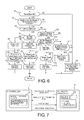
- FIG. 7 shows the engine start control by the integrated controller 10 and the AT controller 7 and the information exchange by the CAN communication line of the gear shift control in one embodiment of the present invention.
- the necessity of the gear shift priority control in one embodiment of the present invention will be explained.
- a gear shift prohibiting flag is set on the side of the integrated controller 10 that has the information related to the engine start/shutdown control and is output to the AT controller 7.
- the start prohibiting flag is set on the side of the AT controller 7 having the information related to the gear shift control and is set to the integrated controller 10.
- the reason is as follows: when the gear shift prohibiting flag and the start prohibiting flag are set on the integrated controller 10 side, inputting the fine information related to the gear shift control from the AT controller 7 is necessary. With respect to this, instead of the input of the information related to the gear shift control from the AT controller 7, it is possible to set the start prohibiting flag with a high degree of precision.
- the AT controller 7 includes a gear shift pattern control section 7a.
- this gear shift pattern control section 7a basically, when there is a request for the engine start, the up gear shift request is not accepted.
- the integrated controller 10 includes the engine start determining section 10a, and this engine start determining section 10a determines whether the engine starts based on the necessary information.
- the integrated controller 10 carries out the start request determination and the final start execution determination and sends the result to the AT controller 7.
- the AT controller 7 sets the start prohibiting flag during the gear shift request and the gear shift control and sends the result to the integrated controller 10.
- the start prohibiting flag is not sent from the AT controller 7 in the last round operation job, so that, in the next-round operation job, the integrated controller 10 determines the start request and the final start execution.
- the start prohibiting flag is sent by the AT controller 7 at the same time as the start request and the final start execution determination, the engine start is carried out in the start prohibiting region. In order to prohibit the engine start in the start prohibiting region, carrying out the gear shift priority control is necessary.
- FIG. 8 is a diagram illustrating an example of the driving point operation pattern on the map when a prediction is made that the up gear shift request and the engine start request are output at the same time when the gear shift priority control in one embodiment of the present invention is adopted. Based on FIG. 8 , an example of the adoption of the gear shift priority control in one embodiment of the present invention will be explained.
- the horizontal line represents the vehicle speed VSP
- the vertical line represents the accelerator position opening APO. Due to the shift of the driving point (VSP, APO), as the driving point crosses the up gear shift line, an up gear shift request is generated; when the driving point crosses the engine start line (EV ⁇ HEV line), an engine start request is generated. Consequently, as shown in FIG. 8 , in the vicinity of the engine start line and the up gear shift line, even when the accelerator compression patterns by the driver are found to be almost the same, the performance still varies due to the shifting pattern of the driving point (VSP, APO).
- the up gear shift is carried out after the engine start.
- the driving point (VSP, APO) shifts as indicated by the arrow D in FIG. 8
- the engine starts after the up gear shift.
- the driving point (VSP, APO) shifts as indicated by the arrow E in FIG. 8
- the up gear shift and the engine start take place at almost the same time.
- step S1 step S2 ⁇ RETURN. That is, in step S2, the engine start control and the gear shift control are carried out according to the gear shift request, the start request, the start prohibiting flag and the gear shift prohibiting flag.
- step S1 When the vehicle makes an accelerated running from the EV start, if the precondition, the simultaneous output prediction condition and the gear shift priority permission condition are all met, in the flow chart shown in FIG. 6 , the following flow is carried out: step S1 ⁇ step S3 ⁇ step S4 ⁇ step S5 ⁇ step S6.
- step S6 the priority gear shift command is output; based on the output of the gear shift priority command, the predicted up gear shift control is started.
- step S7 a determination is made regarding whether the start prohibiting flag is OFF and whether there is the start request. If the determination result is YES, the operation goes to step S8, and the engine start command is output.
- the following time sequence is adopted: the output of the start request according to the prediction timing ⁇ the output of the gear shift request or the start request according to the crossing of the gear shift line or the start line ⁇ the output of the engine start command. That is, the time difference process that the output of the gear shift command is prior to the output of the engine start command is guaranteed. Consequently, even when there is a communication delay via the CAN communication line 11 and an operation delay between the integrated controller 10 and the AT controller 7, it is still possible to reliably avoid the problem of simultaneous processing of entering the engine start mode in the start prohibiting region during the gear shift control by means of the gear shift priority command based on the prediction.
- the gear shift priority command is output at the time of the determination of the simultaneous output prediction condition as the start point of the arrow G shown in FIG. 9 . Consequently, even when the communication delay and the operation delay between the integrated controller 10 and the AT controller 7 exist, it is still possible to prevent the generation of a large shock caused by entering the engine start in the start prohibiting region during the gear shift control.
- step S1 ⁇ step S3 ⁇ step S4 ⁇ step S5 ⁇ step S9.
- step S9 the engine start command is output, and, based on the output of this engine start command, the engine start control is started with priority.
- step S10 a determination is made whether the gear shift prohibiting flag is OFF and whether there is a gear shift request. If the determination result is YES, the operation goes to step S11, and the gear shift command is output.
- the accelerator position variation rate ⁇ APO is taken to be in the range over the first reference value A and below the second reference value B.
- the gear shift control is carried out, and no problem takes place by avoiding the simultaneous control of the engine start control and the gear shift control.
- the accelerator position variation rate ⁇ APO is below the first reference value A.
- the engine start control and the gear shift control are carried out according to the gear shift request, the start request, the start prohibiting flag, and the gear shift prohibiting flag.
- the precondition includes the accelerated running from the established EV start, etc.
- step S1 ⁇ step S3 ( ⁇ step S4) ⁇ step S12 ⁇ step S 13 ⁇ step S 14.
- step S 14 the start prohibiting flag at ON is taken as the priority; based on the output of this start prohibiting flag equal to 0, the engine start is prohibited even when there is an engine start request during the up gear shift control.
- step S 15 a determination is made regarding whether the torque phase carried out as a continuation of the preprocess in the gear shift control has ended.
- step S16 the start prohibiting flag is switched from ON to OFF.
- the gear shift command gear ratio NEXTGP_MAP becomes ON; at the time t3, the control gear ratio NEXTGP becomes ON. Then, at the time t6, the current gear ratio CURGP becomes ON.
- the process from the time t1 to the time t3 is the preprocess. As the preprocess ends according to the gear ratio or the timer, it is possible to back calculate from the timer value to have the priority for the start prohibiting flag at the time t2.
- the configuration in which the start prohibiting flag is set as priority is adopted. According to the configuration of the priority for the start prohibiting flag, when the simultaneous output prediction condition is not met, it is possible to prevent the generation of a large shock caused by entering the engine start in the start prohibiting region during the gear shift due to the CAN communication delay between the integrated controller 10 and the AT controller 7 and due to the delay in the operation.
- the precondition includes the accelerated running from the established EV start, etc.
- step S1 ⁇ step S3 ( ⁇ step S4) ⁇ step S12 ( ⁇ step S 13) ⁇ step S17 ⁇ step S 18.
- step S 18 once the start command or the gear shift command is cancelled, a time corresponding to the communication delay is shifted, and the cancelled command is output again to carry out the simultaneous process prohibiting control.
- the start request and the gear shift request take place at the same time.
- the start prohibiting flag is set during the preprocess of the gear shift control, from the time t0 when the start prohibiting flag is turned down, the engine start begins according to the start request flag, and the gear shift control is cancelled.
- the gear shift control is cancelled, after that, the cancelled gear shift request is generated again.
- the gear shift prohibiting flag is set as determined according to the gear shift line, the operation follows the gear shift line.
- the operation search in the simultaneous process prohibiting control is as follows.
- the control device of the FR hybrid vehicle comprises an engine ENG, a motor (motor/generator MG) that is arranged in the driving system between the engine ENG and the left rear wheel RL and right rear wheel RR, and carries out driving for the start of the engine ENG and driving of the left rear wheel RL and right rear wheel RR, a mode switching means (the first clutch CL1) that is arranged in the connecting section between the engine ENG and the motor (motor/generator MG), and enacts mode switching between the hybrid vehicle mode (HEV mode) that takes both the engine ENG and the motor (motor/generator MG) as the driving source and the electrically driven vehicle mode (EV mode) that takes only the motor (motor/generator MG) as the driving source, an automatic transmission AT that is included between the motor (motor/generator MG) and the left rear wheel RL and right rear wheel RR and comprises plural gear-shift steps with different gear-shift ratios, respectively, and controllers (the integrated controller 10 and the AT controller 7) that carry
- the controller (the integrated controller 10) outputs a gear shift command prior to the engine start command when the simultaneous output prediction condition that predicts the simultaneous output of the gear shift request and the start request at the same time is met (YES in step S3 and step S4), and the gear shift command priority permission condition that permits the priority of the gear shift command based on the gear shift request is met (YES in step S5) ( FIG. 6 ). Consequently, when the simultaneous output prediction condition and the gear shift command priority permission condition are met at the same time, it is possible to initiate the gear shift control reliably prior to the engine start by outputting the gear shift command prior to the engine start command.
- the controller (the integrated controller 10) includes a start prohibiting flag priority control section (step S 14) that outputs a start prohibiting flag prior to the gear shift prohibiting flag when the simultaneous output prediction condition that predicts simultaneous the output of the gear shift request and the start request at the same time is not met (NO in step S3 and step S4), and the start prohibiting priority permission condition that permits the start prohibiting flag with priority (YES in step S12 and step S13) ( FIG. 6 ).
- the controllers include the engine start controller (the integrated controller 10) and the gear shift controller (the AT controller 7) that allow for information exchange by communication.
- the controller (the integrated controller 10) has a simultaneous process prohibiting section (step S 18) that works as follows: when the simultaneous output prediction condition that predicts simultaneous output of the gear shift request and the start request at the same time is not met (NO in step S3 and step S4), when the start prohibiting priority permission condition that permits the start prohibiting flag with priority is not met (NO in step S12 and step S13), and when the start request and the gear shift request are output at the same time (YES in step S 17), once the start command or the gear shift command is cancelled, after the time is shifted corresponding to the delay in communication, the command is output again ( FIG. 6 ).
- control device of the hybrid vehicle has been explained with reference to one embodiment of the invention.
- specific configuration is not limited to this one embodiment.
- various modifications and additions to the design can be made.
- One embodiment of the invention shows an example in which the second clutch CL2 is selected from the frictional elements included in the step-type automatic transmission AT.
- the second clutch CL2 is arranged separated from the automatic transmission AT.
- the second clutch CL2 may be arranged separated from the automatic transmission AT between the motor/generator MG and the input shaft of the transmission, or the second clutch CL2 may be arranged separated from the automatic transmission AT between the output shaft of the transmission and the drive wheels.
- the automatic transmission AT is a step-type automatic transmission having 7 forward gear-shift steps and 1 backwards gear-shift step.
- the number of the gear-shift steps is not limited to this example.
- the automatic transmission may have plural gear-shift steps of 2 or more.
- the mode switching means between the HEV mode and the EV mode the first clutch CL1 is shown.
- another mode switching means may be adopted for switching between the HEV mode and the EV mode.
- one may adopt a differential apparatus or a power dividing apparatus that can display the clutch function without using a clutch, such as planetary gear, etc.
- control device in one embodiment of the present invention, an example of the adoption of the control device in a rear-wheel drive hybrid vehicle is shown.
- control device may also be adopted on a front-wheel drive hybrid vehicle.
- control device may be adopted on any hybrid vehicle that carries an automatic transmission and includes the HEV mode and the EV mode as the running modes.
- the integrated controller 10 and the AT controller 7 that can exchange information by communication are presented as an example.
- the present invention may also be adopted with an apparatus that has these controllers integrated in a single controller, and the single controller can have both the function corresponding to the integrated controller 10 and the function corresponding to the AT controller 7 in one embodiment of the present invention.
Applications Claiming Priority (2)
| Application Number | Priority Date | Filing Date | Title |
|---|---|---|---|
| JP2010237261 | 2010-10-22 | ||
| PCT/JP2011/074283 WO2012053633A1 (ja) | 2010-10-22 | 2011-10-21 | ハイブリッド車両の制御装置 |
Publications (3)
| Publication Number | Publication Date |
|---|---|
| EP2631142A1 true EP2631142A1 (de) | 2013-08-28 |
| EP2631142A4 EP2631142A4 (de) | 2018-05-02 |
| EP2631142B1 EP2631142B1 (de) | 2019-09-18 |
Family
ID=45975341
Family Applications (1)
| Application Number | Title | Priority Date | Filing Date |
|---|---|---|---|
| EP11834472.0A Active EP2631142B1 (de) | 2010-10-22 | 2011-10-21 | Steuerungsvorrichtung für ein hybridfahrzeug |
Country Status (5)
| Country | Link |
|---|---|
| US (1) | US8868276B2 (de) |
| EP (1) | EP2631142B1 (de) |
| JP (1) | JP5578238B2 (de) |
| CN (1) | CN103370246B (de) |
| WO (1) | WO2012053633A1 (de) |
Families Citing this family (32)
| Publication number | Priority date | Publication date | Assignee | Title |
|---|---|---|---|---|
| JP5817136B2 (ja) * | 2011-02-16 | 2015-11-18 | 日産自動車株式会社 | エンジンの始動装置の保護装置 |
| DE102011078670A1 (de) * | 2011-07-05 | 2013-01-10 | Zf Friedrichshafen Ag | Verfahren zum Betreiben eines Hybridantriebsstrangs eines Fahrzeugs |
| US9156468B2 (en) * | 2011-09-06 | 2015-10-13 | Toyota Jidosha Kabushiki Kaisha | Control device for hybrid vehicle |
| JP2013203287A (ja) * | 2012-03-29 | 2013-10-07 | Denso Corp | ハイブリッド車の制御装置 |
| CN104884322B (zh) * | 2012-12-25 | 2017-07-25 | 日产自动车株式会社 | 混合动力车辆的控制装置 |
| MX347640B (es) * | 2013-04-04 | 2017-05-05 | Nissan Motor | Dispositivo de control de vehiculo hibrido. |
| KR101976858B1 (ko) * | 2013-06-11 | 2019-05-09 | 현대자동차주식회사 | 유단 변속기를 장착한 하이브리드 자동차의 제어 방법 |
| KR101500374B1 (ko) * | 2013-09-23 | 2015-03-09 | 현대자동차 주식회사 | 하이브리드 차량의 시프트 다운 제어 방법 및 시스템 |
| US9193353B2 (en) * | 2013-10-30 | 2015-11-24 | GM Global Technology Operations LLC | Systems and methods for controlling an automatic transmission during a flying engine start using a flow accumulator |
| US9533677B2 (en) * | 2014-08-26 | 2017-01-03 | Ford Global Technologies, Llc | Method of transitioning among shift schedules |
| JP6420653B2 (ja) * | 2014-12-11 | 2018-11-07 | 株式会社エフ・シー・シー | ハイブリッド車両の動力伝達装置 |
| US9731706B2 (en) | 2015-03-24 | 2017-08-15 | Ford Global Technologies, Llc | Coordinating non-demand engine start and stop with gear shift |
| CN107428333B (zh) * | 2015-03-31 | 2019-11-05 | 爱信艾达株式会社 | 控制装置 |
| MX363874B (es) * | 2015-06-03 | 2019-04-05 | Nissan Motor | Dispositivo de control de transicion de modo para vehiculo hibrido. |
| DE102015211572A1 (de) * | 2015-06-23 | 2016-12-29 | Robert Bosch Gmbh | Verfahren zur Steuerung eines Start-/Stopp-Systems eines Hybridkraftfahrzeugs |
| KR101694074B1 (ko) * | 2015-11-10 | 2017-01-18 | 현대자동차주식회사 | 하이브리드 dct 차량의 변속 제어방법 |
| JP6561978B2 (ja) * | 2016-12-21 | 2019-08-21 | トヨタ自動車株式会社 | ハイブリッド車両およびその制御方法 |
| JP6540680B2 (ja) * | 2016-12-26 | 2019-07-10 | トヨタ自動車株式会社 | ハイブリッド車両 |
| DE102017214787A1 (de) * | 2017-08-23 | 2019-02-28 | Bayerische Motoren Werke Aktiengesellschaft | Impulsstart in einem Hybrid-Antriebsstrang |
| JP6855986B2 (ja) | 2017-09-04 | 2021-04-07 | トヨタ自動車株式会社 | ハイブリッド車両の駆動力制御装置 |
| CN109094553B (zh) * | 2018-09-06 | 2020-07-10 | 重庆长安汽车股份有限公司 | 混合动力汽车及其发动机启动控制方法 |
| JP7172689B2 (ja) * | 2019-02-08 | 2022-11-16 | トヨタ自動車株式会社 | 車両の制御装置 |
| JP7081541B2 (ja) * | 2019-03-20 | 2022-06-07 | トヨタ自動車株式会社 | 車両の制御装置 |
| CN112824178B (zh) * | 2019-11-21 | 2022-04-05 | 广州汽车集团股份有限公司 | 行星齿轮机构控制方法、装置、控制器和可读存储介质 |
| DE102020201374A1 (de) | 2020-02-05 | 2021-08-05 | Zf Friedrichshafen Ag | Verfahren zum Betreiben eines Hybridfahrzeugs |
| US11846085B2 (en) | 2020-02-17 | 2023-12-19 | Deere & Company | Energy management system for a hybrid vehicle with an electrically powered hydraulic system |
| US11613246B2 (en) * | 2021-01-21 | 2023-03-28 | Deere & Company | Power control system with engine throttle shift function |
| US11628822B2 (en) | 2021-02-09 | 2023-04-18 | Deere & Company | Power control system with stall prevention clutch modulation function |
| US11820361B2 (en) | 2021-11-30 | 2023-11-21 | Deere & Company | Transmission assembly with electrical machine unit for improved shift quality |
| US11585412B1 (en) | 2021-12-22 | 2023-02-21 | Deere & Company | Electronically-variable, dual-path power shift transmission for work vehicles |
| US11607948B1 (en) | 2021-12-22 | 2023-03-21 | Deere & Company | Electronically-variable power shift transmission for work vehicles |
| US11913528B1 (en) | 2022-10-28 | 2024-02-27 | Deere & Company | Multi-mode continuously variable transmission assembly with drop set arrangement |
Family Cites Families (19)
| Publication number | Priority date | Publication date | Assignee | Title |
|---|---|---|---|---|
| JPH102241A (ja) | 1996-04-19 | 1998-01-06 | Toyota Motor Corp | ハイブリッド車両の制御装置 |
| US5982045A (en) * | 1996-04-19 | 1999-11-09 | Toyota Jidosha Kabushiki Kaisha | Hybrid vehicle drive system adapted to prevent concurrent mode change and transmission shifting or torque distribution ratio change |
| JP3963868B2 (ja) * | 2003-06-23 | 2007-08-22 | トヨタ自動車株式会社 | ハイブリッド駆動装置の制御装置 |
| JP2006123642A (ja) * | 2004-10-27 | 2006-05-18 | Aisin Aw Co Ltd | ハイブリッド車用駆動装置、その制御方法及び制御装置 |
| JP4341611B2 (ja) * | 2005-11-09 | 2009-10-07 | 日産自動車株式会社 | ハイブリッド車両のエンジン再始動制御装置 |
| JP2006315484A (ja) * | 2005-05-11 | 2006-11-24 | Nissan Motor Co Ltd | 車両用ハイブリッド駆動装置のモード切り替え制御装置 |
| JP4466514B2 (ja) * | 2005-09-08 | 2010-05-26 | 日産自動車株式会社 | ハイブリッド車両のエンジン始動制御装置 |
| JP4234710B2 (ja) * | 2005-10-26 | 2009-03-04 | トヨタ自動車株式会社 | 電動車両駆動制御装置及びその制御方法 |
| US7670258B2 (en) * | 2006-06-15 | 2010-03-02 | Toyota Jidosha Kabushiki Kaisha | Control device for vehicle drive apparatus |
| JP2008137619A (ja) * | 2006-12-05 | 2008-06-19 | Toyota Motor Corp | 車両用駆動装置の制御装置 |
| JP5076516B2 (ja) * | 2007-01-24 | 2012-11-21 | 日産自動車株式会社 | ハイブリッド車両の変速時モード切り替え制御装置 |
| US8204659B2 (en) * | 2007-03-12 | 2012-06-19 | Nissan Motor Co., Ltd. | Engine start control system for hybrid vehicle |
| JP5125199B2 (ja) * | 2007-04-20 | 2013-01-23 | トヨタ自動車株式会社 | ハイブリッド車両のエンジン始動制御装置 |
| JP4501956B2 (ja) * | 2007-04-20 | 2010-07-14 | トヨタ自動車株式会社 | ハイブリッド車両用駆動装置の制御装置 |
| JP5082669B2 (ja) * | 2007-08-10 | 2012-11-28 | トヨタ自動車株式会社 | ハイブリッド車両用動力伝達装置の制御装置 |
| JP5228677B2 (ja) * | 2008-07-30 | 2013-07-03 | 日産自動車株式会社 | ハイブリッド車両の制御装置 |
| JP2010083351A (ja) * | 2008-09-30 | 2010-04-15 | Mazda Motor Corp | 車両用駆動装置の制御方法 |
| JP2010215189A (ja) * | 2009-03-18 | 2010-09-30 | Toyota Motor Corp | 車両用駆動装置 |
| JP5742124B2 (ja) * | 2010-07-21 | 2015-07-01 | 日産自動車株式会社 | ハイブリッド車両の制御装置 |
-
2011
- 2011-10-21 US US13/879,776 patent/US8868276B2/en active Active
- 2011-10-21 CN CN201180062572.7A patent/CN103370246B/zh active Active
- 2011-10-21 EP EP11834472.0A patent/EP2631142B1/de active Active
- 2011-10-21 WO PCT/JP2011/074283 patent/WO2012053633A1/ja active Application Filing
- 2011-10-21 JP JP2012539781A patent/JP5578238B2/ja active Active
Non-Patent Citations (1)
| Title |
|---|
| See references of WO2012053633A1 * |
Also Published As
| Publication number | Publication date |
|---|---|
| JP5578238B2 (ja) | 2014-08-27 |
| WO2012053633A1 (ja) | 2012-04-26 |
| CN103370246B (zh) | 2015-12-16 |
| US8868276B2 (en) | 2014-10-21 |
| JPWO2012053633A1 (ja) | 2014-02-24 |
| US20130231815A1 (en) | 2013-09-05 |
| CN103370246A (zh) | 2013-10-23 |
| EP2631142B1 (de) | 2019-09-18 |
| EP2631142A4 (de) | 2018-05-02 |
Similar Documents
| Publication | Publication Date | Title |
|---|---|---|
| EP2631142B1 (de) | Steuerungsvorrichtung für ein hybridfahrzeug | |
| EP2595849B1 (de) | Vorrichtung und verfahren zur steuerung von hybridfahrzeugen | |
| EP2669132B1 (de) | Steuervorrichtung für ein hybridfahrzeug | |
| EP1792800B1 (de) | Steuerung für Hybrid-Fahrzeug | |
| EP2669125B1 (de) | Steuervorrichtung für ein hybridfahrzeug | |
| EP1839987A2 (de) | Antriebsmodussteuerung | |
| JP5163093B2 (ja) | ハイブリッド車両の制御装置 | |
| JP4973113B2 (ja) | 車両の制御装置 | |
| KR20140010191A (ko) | 하이브리드 차량의 제어 장치 | |
| CN104417543A (zh) | 混合动力汽车的控制系统和控制方法 | |
| JP2007069787A (ja) | ハイブリッド車両の減速制御装置 | |
| KR20120089597A (ko) | 하이브리드 차량의 제어 장치 | |
| JP5789997B2 (ja) | ハイブリッド車輌の制御装置 | |
| JP5181847B2 (ja) | 複合ブレーキの協調制御装置 | |
| JP5233642B2 (ja) | ハイブリッド車両の制御装置 | |
| WO2013150966A1 (ja) | ハイブリッド車両の制御装置およびハイブリッド車両の制御方法 | |
| JP6004026B2 (ja) | 電動車両の制御装置 | |
| JP5601964B2 (ja) | ハイブリッド車両の制御装置 | |
| JP2012086751A (ja) | 電動車両の制御装置 | |
| JP2012091550A (ja) | ハイブリッド車両の制御装置 |
Legal Events
| Date | Code | Title | Description |
|---|---|---|---|
| PUAI | Public reference made under article 153(3) epc to a published international application that has entered the european phase |
Free format text: ORIGINAL CODE: 0009012 |
|
| 17P | Request for examination filed |
Effective date: 20130521 |
|
| AK | Designated contracting states |
Kind code of ref document: A1 Designated state(s): AL AT BE BG CH CY CZ DE DK EE ES FI FR GB GR HR HU IE IS IT LI LT LU LV MC MK MT NL NO PL PT RO RS SE SI SK SM TR |
|
| DAX | Request for extension of the european patent (deleted) | ||
| RA4 | Supplementary search report drawn up and despatched (corrected) |
Effective date: 20180404 |
|
| RIC1 | Information provided on ipc code assigned before grant |
Ipc: B60W 20/40 20160101ALI20180327BHEP Ipc: B60W 10/04 20060101ALI20180327BHEP Ipc: B60L 15/20 20060101ALI20180327BHEP Ipc: F02D 29/02 20060101ALI20180327BHEP Ipc: B60W 30/192 20120101ALI20180327BHEP Ipc: B60W 20/00 20060101ALI20180327BHEP Ipc: B60W 10/06 20060101ALI20180327BHEP Ipc: B60W 30/19 20120101ALI20180327BHEP Ipc: B60K 6/36 20071001ALI20180327BHEP Ipc: B60K 6/48 20071001ALI20180327BHEP Ipc: B60W 10/10 20120101AFI20180327BHEP Ipc: B60K 6/547 20071001ALI20180327BHEP Ipc: B60L 11/14 20060101ALI20180327BHEP Ipc: B60W 10/115 20120101ALI20180327BHEP Ipc: B60W 10/08 20060101ALI20180327BHEP Ipc: B60W 20/30 20160101ALI20180327BHEP Ipc: F02D 29/00 20060101ALI20180327BHEP Ipc: B60W 10/11 20120101ALI20180327BHEP |
|
| RIC1 | Information provided on ipc code assigned before grant |
Ipc: B60W 30/19 20120101ALI20180327BHEP Ipc: F02D 29/02 20060101ALI20180327BHEP Ipc: B60K 6/547 20071001ALI20180327BHEP Ipc: B60W 30/192 20120101ALI20180327BHEP Ipc: B60W 20/30 20160101ALI20180327BHEP Ipc: B60W 10/115 20120101ALI20180327BHEP Ipc: B60W 20/40 20160101ALI20180327BHEP Ipc: F02D 29/00 20060101ALI20180327BHEP Ipc: B60W 10/08 20060101ALI20180327BHEP Ipc: B60W 10/11 20120101ALI20180327BHEP Ipc: B60W 10/10 20120101AFI20180327BHEP Ipc: B60L 11/14 20060101ALI20180327BHEP Ipc: B60W 10/06 20060101ALI20180327BHEP Ipc: B60W 10/04 20060101ALI20180327BHEP Ipc: B60K 6/48 20071001ALI20180327BHEP Ipc: B60W 20/00 20160101ALI20180327BHEP Ipc: B60L 15/20 20060101ALI20180327BHEP Ipc: B60K 6/36 20071001ALI20180327BHEP |
|
| REG | Reference to a national code |
Ref country code: DE Ref legal event code: R079 Ref document number: 602011062213 Country of ref document: DE Free format text: PREVIOUS MAIN CLASS: B60W0010100000 Ipc: B60L0050160000 |
|
| GRAP | Despatch of communication of intention to grant a patent |
Free format text: ORIGINAL CODE: EPIDOSNIGR1 |
|
| STAA | Information on the status of an ep patent application or granted ep patent |
Free format text: STATUS: GRANT OF PATENT IS INTENDED |
|
| RIC1 | Information provided on ipc code assigned before grant |
Ipc: B60K 6/48 20071001ALI20190430BHEP Ipc: B60L 50/16 20190101AFI20190430BHEP Ipc: B60W 20/30 20160101ALI20190430BHEP Ipc: B60W 30/19 20120101ALI20190430BHEP Ipc: B60W 10/115 20120101ALI20190430BHEP Ipc: B60W 20/40 20160101ALI20190430BHEP Ipc: B60W 10/08 20060101ALI20190430BHEP Ipc: B60K 6/36 20071001ALI20190430BHEP Ipc: B60W 30/192 20120101ALI20190430BHEP Ipc: B60W 20/00 20160101ALI20190430BHEP Ipc: B60L 15/20 20060101ALI20190430BHEP Ipc: B60W 10/06 20060101ALI20190430BHEP |
|
| INTG | Intention to grant announced |
Effective date: 20190521 |
|
| GRAS | Grant fee paid |
Free format text: ORIGINAL CODE: EPIDOSNIGR3 |
|
| GRAA | (expected) grant |
Free format text: ORIGINAL CODE: 0009210 |
|
| STAA | Information on the status of an ep patent application or granted ep patent |
Free format text: STATUS: THE PATENT HAS BEEN GRANTED |
|
| AK | Designated contracting states |
Kind code of ref document: B1 Designated state(s): AL AT BE BG CH CY CZ DE DK EE ES FI FR GB GR HR HU IE IS IT LI LT LU LV MC MK MT NL NO PL PT RO RS SE SI SK SM TR |
|
| REG | Reference to a national code |
Ref country code: GB Ref legal event code: FG4D |
|
| REG | Reference to a national code |
Ref country code: CH Ref legal event code: EP |
|
| REG | Reference to a national code |
Ref country code: DE Ref legal event code: R096 Ref document number: 602011062213 Country of ref document: DE |
|
| REG | Reference to a national code |
Ref country code: AT Ref legal event code: REF Ref document number: 1180871 Country of ref document: AT Kind code of ref document: T Effective date: 20191015 |
|
| REG | Reference to a national code |
Ref country code: IE Ref legal event code: FG4D |
|
| REG | Reference to a national code |
Ref country code: NL Ref legal event code: MP Effective date: 20190918 |
|
| PG25 | Lapsed in a contracting state [announced via postgrant information from national office to epo] |
Ref country code: FI Free format text: LAPSE BECAUSE OF FAILURE TO SUBMIT A TRANSLATION OF THE DESCRIPTION OR TO PAY THE FEE WITHIN THE PRESCRIBED TIME-LIMIT Effective date: 20190918 Ref country code: NO Free format text: LAPSE BECAUSE OF FAILURE TO SUBMIT A TRANSLATION OF THE DESCRIPTION OR TO PAY THE FEE WITHIN THE PRESCRIBED TIME-LIMIT Effective date: 20191218 Ref country code: HR Free format text: LAPSE BECAUSE OF FAILURE TO SUBMIT A TRANSLATION OF THE DESCRIPTION OR TO PAY THE FEE WITHIN THE PRESCRIBED TIME-LIMIT Effective date: 20190918 Ref country code: LT Free format text: LAPSE BECAUSE OF FAILURE TO SUBMIT A TRANSLATION OF THE DESCRIPTION OR TO PAY THE FEE WITHIN THE PRESCRIBED TIME-LIMIT Effective date: 20190918 Ref country code: SE Free format text: LAPSE BECAUSE OF FAILURE TO SUBMIT A TRANSLATION OF THE DESCRIPTION OR TO PAY THE FEE WITHIN THE PRESCRIBED TIME-LIMIT Effective date: 20190918 Ref country code: BG Free format text: LAPSE BECAUSE OF FAILURE TO SUBMIT A TRANSLATION OF THE DESCRIPTION OR TO PAY THE FEE WITHIN THE PRESCRIBED TIME-LIMIT Effective date: 20191218 |
|
| REG | Reference to a national code |
Ref country code: LT Ref legal event code: MG4D |
|
| PG25 | Lapsed in a contracting state [announced via postgrant information from national office to epo] |
Ref country code: GR Free format text: LAPSE BECAUSE OF FAILURE TO SUBMIT A TRANSLATION OF THE DESCRIPTION OR TO PAY THE FEE WITHIN THE PRESCRIBED TIME-LIMIT Effective date: 20191219 Ref country code: LV Free format text: LAPSE BECAUSE OF FAILURE TO SUBMIT A TRANSLATION OF THE DESCRIPTION OR TO PAY THE FEE WITHIN THE PRESCRIBED TIME-LIMIT Effective date: 20190918 Ref country code: AL Free format text: LAPSE BECAUSE OF FAILURE TO SUBMIT A TRANSLATION OF THE DESCRIPTION OR TO PAY THE FEE WITHIN THE PRESCRIBED TIME-LIMIT Effective date: 20190918 Ref country code: RS Free format text: LAPSE BECAUSE OF FAILURE TO SUBMIT A TRANSLATION OF THE DESCRIPTION OR TO PAY THE FEE WITHIN THE PRESCRIBED TIME-LIMIT Effective date: 20190918 |
|
| REG | Reference to a national code |
Ref country code: AT Ref legal event code: MK05 Ref document number: 1180871 Country of ref document: AT Kind code of ref document: T Effective date: 20190918 |
|
| PG25 | Lapsed in a contracting state [announced via postgrant information from national office to epo] |
Ref country code: RO Free format text: LAPSE BECAUSE OF FAILURE TO SUBMIT A TRANSLATION OF THE DESCRIPTION OR TO PAY THE FEE WITHIN THE PRESCRIBED TIME-LIMIT Effective date: 20190918 Ref country code: IT Free format text: LAPSE BECAUSE OF FAILURE TO SUBMIT A TRANSLATION OF THE DESCRIPTION OR TO PAY THE FEE WITHIN THE PRESCRIBED TIME-LIMIT Effective date: 20190918 Ref country code: PL Free format text: LAPSE BECAUSE OF FAILURE TO SUBMIT A TRANSLATION OF THE DESCRIPTION OR TO PAY THE FEE WITHIN THE PRESCRIBED TIME-LIMIT Effective date: 20190918 Ref country code: NL Free format text: LAPSE BECAUSE OF FAILURE TO SUBMIT A TRANSLATION OF THE DESCRIPTION OR TO PAY THE FEE WITHIN THE PRESCRIBED TIME-LIMIT Effective date: 20190918 Ref country code: AT Free format text: LAPSE BECAUSE OF FAILURE TO SUBMIT A TRANSLATION OF THE DESCRIPTION OR TO PAY THE FEE WITHIN THE PRESCRIBED TIME-LIMIT Effective date: 20190918 Ref country code: PT Free format text: LAPSE BECAUSE OF FAILURE TO SUBMIT A TRANSLATION OF THE DESCRIPTION OR TO PAY THE FEE WITHIN THE PRESCRIBED TIME-LIMIT Effective date: 20200120 Ref country code: ES Free format text: LAPSE BECAUSE OF FAILURE TO SUBMIT A TRANSLATION OF THE DESCRIPTION OR TO PAY THE FEE WITHIN THE PRESCRIBED TIME-LIMIT Effective date: 20190918 Ref country code: EE Free format text: LAPSE BECAUSE OF FAILURE TO SUBMIT A TRANSLATION OF THE DESCRIPTION OR TO PAY THE FEE WITHIN THE PRESCRIBED TIME-LIMIT Effective date: 20190918 |
|
| PG25 | Lapsed in a contracting state [announced via postgrant information from national office to epo] |
Ref country code: CZ Free format text: LAPSE BECAUSE OF FAILURE TO SUBMIT A TRANSLATION OF THE DESCRIPTION OR TO PAY THE FEE WITHIN THE PRESCRIBED TIME-LIMIT Effective date: 20190918 Ref country code: SM Free format text: LAPSE BECAUSE OF FAILURE TO SUBMIT A TRANSLATION OF THE DESCRIPTION OR TO PAY THE FEE WITHIN THE PRESCRIBED TIME-LIMIT Effective date: 20190918 Ref country code: IS Free format text: LAPSE BECAUSE OF FAILURE TO SUBMIT A TRANSLATION OF THE DESCRIPTION OR TO PAY THE FEE WITHIN THE PRESCRIBED TIME-LIMIT Effective date: 20200224 Ref country code: SK Free format text: LAPSE BECAUSE OF FAILURE TO SUBMIT A TRANSLATION OF THE DESCRIPTION OR TO PAY THE FEE WITHIN THE PRESCRIBED TIME-LIMIT Effective date: 20190918 |
|
| REG | Reference to a national code |
Ref country code: CH Ref legal event code: PL |
|
| REG | Reference to a national code |
Ref country code: DE Ref legal event code: R097 Ref document number: 602011062213 Country of ref document: DE |
|
| PLBE | No opposition filed within time limit |
Free format text: ORIGINAL CODE: 0009261 |
|
| STAA | Information on the status of an ep patent application or granted ep patent |
Free format text: STATUS: NO OPPOSITION FILED WITHIN TIME LIMIT |
|
| PG2D | Information on lapse in contracting state deleted |
Ref country code: IS |
|
| PG25 | Lapsed in a contracting state [announced via postgrant information from national office to epo] |
Ref country code: DK Free format text: LAPSE BECAUSE OF FAILURE TO SUBMIT A TRANSLATION OF THE DESCRIPTION OR TO PAY THE FEE WITHIN THE PRESCRIBED TIME-LIMIT Effective date: 20190918 Ref country code: LI Free format text: LAPSE BECAUSE OF NON-PAYMENT OF DUE FEES Effective date: 20191031 Ref country code: CH Free format text: LAPSE BECAUSE OF NON-PAYMENT OF DUE FEES Effective date: 20191031 Ref country code: LU Free format text: LAPSE BECAUSE OF NON-PAYMENT OF DUE FEES Effective date: 20191021 Ref country code: IS Free format text: LAPSE BECAUSE OF FAILURE TO SUBMIT A TRANSLATION OF THE DESCRIPTION OR TO PAY THE FEE WITHIN THE PRESCRIBED TIME-LIMIT Effective date: 20200119 |
|
| REG | Reference to a national code |
Ref country code: BE Ref legal event code: MM Effective date: 20191031 |
|
| 26N | No opposition filed |
Effective date: 20200619 |
|
| PG25 | Lapsed in a contracting state [announced via postgrant information from national office to epo] |
Ref country code: BE Free format text: LAPSE BECAUSE OF NON-PAYMENT OF DUE FEES Effective date: 20191031 Ref country code: SI Free format text: LAPSE BECAUSE OF FAILURE TO SUBMIT A TRANSLATION OF THE DESCRIPTION OR TO PAY THE FEE WITHIN THE PRESCRIBED TIME-LIMIT Effective date: 20190918 Ref country code: MC Free format text: LAPSE BECAUSE OF FAILURE TO SUBMIT A TRANSLATION OF THE DESCRIPTION OR TO PAY THE FEE WITHIN THE PRESCRIBED TIME-LIMIT Effective date: 20190918 |
|
| PG25 | Lapsed in a contracting state [announced via postgrant information from national office to epo] |
Ref country code: IE Free format text: LAPSE BECAUSE OF NON-PAYMENT OF DUE FEES Effective date: 20191021 |
|
| PG25 | Lapsed in a contracting state [announced via postgrant information from national office to epo] |
Ref country code: CY Free format text: LAPSE BECAUSE OF FAILURE TO SUBMIT A TRANSLATION OF THE DESCRIPTION OR TO PAY THE FEE WITHIN THE PRESCRIBED TIME-LIMIT Effective date: 20190918 |
|
| PG25 | Lapsed in a contracting state [announced via postgrant information from national office to epo] |
Ref country code: HU Free format text: LAPSE BECAUSE OF FAILURE TO SUBMIT A TRANSLATION OF THE DESCRIPTION OR TO PAY THE FEE WITHIN THE PRESCRIBED TIME-LIMIT; INVALID AB INITIO Effective date: 20111021 Ref country code: MT Free format text: LAPSE BECAUSE OF FAILURE TO SUBMIT A TRANSLATION OF THE DESCRIPTION OR TO PAY THE FEE WITHIN THE PRESCRIBED TIME-LIMIT Effective date: 20190918 |
|
| PG25 | Lapsed in a contracting state [announced via postgrant information from national office to epo] |
Ref country code: TR Free format text: LAPSE BECAUSE OF FAILURE TO SUBMIT A TRANSLATION OF THE DESCRIPTION OR TO PAY THE FEE WITHIN THE PRESCRIBED TIME-LIMIT Effective date: 20190918 |
|
| PG25 | Lapsed in a contracting state [announced via postgrant information from national office to epo] |
Ref country code: MK Free format text: LAPSE BECAUSE OF FAILURE TO SUBMIT A TRANSLATION OF THE DESCRIPTION OR TO PAY THE FEE WITHIN THE PRESCRIBED TIME-LIMIT Effective date: 20190918 |
|
| PGFP | Annual fee paid to national office [announced via postgrant information from national office to epo] |
Ref country code: GB Payment date: 20230920 Year of fee payment: 13 |
|
| PGFP | Annual fee paid to national office [announced via postgrant information from national office to epo] |
Ref country code: FR Payment date: 20230920 Year of fee payment: 13 |
|
| PGFP | Annual fee paid to national office [announced via postgrant information from national office to epo] |
Ref country code: DE Payment date: 20230920 Year of fee payment: 13 |