EP2608982B1 - Längsverstellvorrichtung für einen fahrzeugsitz mit trennbarer ober- und unterschiene - Google Patents
Längsverstellvorrichtung für einen fahrzeugsitz mit trennbarer ober- und unterschiene Download PDFInfo
- Publication number
- EP2608982B1 EP2608982B1 EP11749161.3A EP11749161A EP2608982B1 EP 2608982 B1 EP2608982 B1 EP 2608982B1 EP 11749161 A EP11749161 A EP 11749161A EP 2608982 B1 EP2608982 B1 EP 2608982B1
- Authority
- EP
- European Patent Office
- Prior art keywords
- rail
- lower rail
- adjusting device
- upper rail
- longitudinal adjusting
- Prior art date
- Legal status (The legal status is an assumption and is not a legal conclusion. Google has not performed a legal analysis and makes no representation as to the accuracy of the status listed.)
- Active
Links
Images

Classifications
-
- B—PERFORMING OPERATIONS; TRANSPORTING
- B60—VEHICLES IN GENERAL
- B60N—SEATS SPECIALLY ADAPTED FOR VEHICLES; VEHICLE PASSENGER ACCOMMODATION NOT OTHERWISE PROVIDED FOR
- B60N2/00—Seats specially adapted for vehicles; Arrangement or mounting of seats in vehicles
- B60N2/02—Seats specially adapted for vehicles; Arrangement or mounting of seats in vehicles the seat or part thereof being movable, e.g. adjustable
- B60N2/04—Seats specially adapted for vehicles; Arrangement or mounting of seats in vehicles the seat or part thereof being movable, e.g. adjustable the whole seat being movable
- B60N2/06—Seats specially adapted for vehicles; Arrangement or mounting of seats in vehicles the seat or part thereof being movable, e.g. adjustable the whole seat being movable slidable
- B60N2/08—Seats specially adapted for vehicles; Arrangement or mounting of seats in vehicles the seat or part thereof being movable, e.g. adjustable the whole seat being movable slidable characterised by the locking device
-
- B—PERFORMING OPERATIONS; TRANSPORTING
- B60—VEHICLES IN GENERAL
- B60N—SEATS SPECIALLY ADAPTED FOR VEHICLES; VEHICLE PASSENGER ACCOMMODATION NOT OTHERWISE PROVIDED FOR
- B60N2/00—Seats specially adapted for vehicles; Arrangement or mounting of seats in vehicles
- B60N2/005—Arrangement or mounting of seats in vehicles, e.g. dismountable auxiliary seats
- B60N2/015—Attaching seats directly to vehicle chassis
- B60N2/01508—Attaching seats directly to vehicle chassis using quick release attachments
- B60N2/01516—Attaching seats directly to vehicle chassis using quick release attachments with locking mechanisms
- B60N2/01525—Attaching seats directly to vehicle chassis using quick release attachments with locking mechanisms with locking elements expanding inside or under the vehicle floor or rail
-
- B—PERFORMING OPERATIONS; TRANSPORTING
- B60—VEHICLES IN GENERAL
- B60N—SEATS SPECIALLY ADAPTED FOR VEHICLES; VEHICLE PASSENGER ACCOMMODATION NOT OTHERWISE PROVIDED FOR
- B60N2/00—Seats specially adapted for vehicles; Arrangement or mounting of seats in vehicles
- B60N2/005—Arrangement or mounting of seats in vehicles, e.g. dismountable auxiliary seats
- B60N2/015—Attaching seats directly to vehicle chassis
- B60N2/01508—Attaching seats directly to vehicle chassis using quick release attachments
- B60N2/01516—Attaching seats directly to vehicle chassis using quick release attachments with locking mechanisms
- B60N2/0155—Attaching seats directly to vehicle chassis using quick release attachments with locking mechanisms with the locking mechanism on the vehicle floor or rail
-
- B—PERFORMING OPERATIONS; TRANSPORTING
- B60—VEHICLES IN GENERAL
- B60N—SEATS SPECIALLY ADAPTED FOR VEHICLES; VEHICLE PASSENGER ACCOMMODATION NOT OTHERWISE PROVIDED FOR
- B60N2/00—Seats specially adapted for vehicles; Arrangement or mounting of seats in vehicles
- B60N2/005—Arrangement or mounting of seats in vehicles, e.g. dismountable auxiliary seats
- B60N2/015—Attaching seats directly to vehicle chassis
- B60N2/01508—Attaching seats directly to vehicle chassis using quick release attachments
- B60N2/01516—Attaching seats directly to vehicle chassis using quick release attachments with locking mechanisms
- B60N2/01558—Attaching seats directly to vehicle chassis using quick release attachments with locking mechanisms with key and slot
- B60N2/01575—Attaching seats directly to vehicle chassis using quick release attachments with locking mechanisms with key and slot key sliding inside the vehicle floor or rail
-
- B—PERFORMING OPERATIONS; TRANSPORTING
- B60—VEHICLES IN GENERAL
- B60N—SEATS SPECIALLY ADAPTED FOR VEHICLES; VEHICLE PASSENGER ACCOMMODATION NOT OTHERWISE PROVIDED FOR
- B60N2/00—Seats specially adapted for vehicles; Arrangement or mounting of seats in vehicles
- B60N2/005—Arrangement or mounting of seats in vehicles, e.g. dismountable auxiliary seats
- B60N2/015—Attaching seats directly to vehicle chassis
- B60N2/01508—Attaching seats directly to vehicle chassis using quick release attachments
- B60N2/01591—Attaching seats directly to vehicle chassis using quick release attachments with wheels coupled to the seat
-
- B—PERFORMING OPERATIONS; TRANSPORTING
- B60—VEHICLES IN GENERAL
- B60N—SEATS SPECIALLY ADAPTED FOR VEHICLES; VEHICLE PASSENGER ACCOMMODATION NOT OTHERWISE PROVIDED FOR
- B60N2/00—Seats specially adapted for vehicles; Arrangement or mounting of seats in vehicles
- B60N2/02—Seats specially adapted for vehicles; Arrangement or mounting of seats in vehicles the seat or part thereof being movable, e.g. adjustable
- B60N2/04—Seats specially adapted for vehicles; Arrangement or mounting of seats in vehicles the seat or part thereof being movable, e.g. adjustable the whole seat being movable
-
- B—PERFORMING OPERATIONS; TRANSPORTING
- B60—VEHICLES IN GENERAL
- B60N—SEATS SPECIALLY ADAPTED FOR VEHICLES; VEHICLE PASSENGER ACCOMMODATION NOT OTHERWISE PROVIDED FOR
- B60N2/00—Seats specially adapted for vehicles; Arrangement or mounting of seats in vehicles
- B60N2/02—Seats specially adapted for vehicles; Arrangement or mounting of seats in vehicles the seat or part thereof being movable, e.g. adjustable
- B60N2/04—Seats specially adapted for vehicles; Arrangement or mounting of seats in vehicles the seat or part thereof being movable, e.g. adjustable the whole seat being movable
- B60N2/06—Seats specially adapted for vehicles; Arrangement or mounting of seats in vehicles the seat or part thereof being movable, e.g. adjustable the whole seat being movable slidable
-
- B—PERFORMING OPERATIONS; TRANSPORTING
- B60—VEHICLES IN GENERAL
- B60N—SEATS SPECIALLY ADAPTED FOR VEHICLES; VEHICLE PASSENGER ACCOMMODATION NOT OTHERWISE PROVIDED FOR
- B60N2/00—Seats specially adapted for vehicles; Arrangement or mounting of seats in vehicles
- B60N2/02—Seats specially adapted for vehicles; Arrangement or mounting of seats in vehicles the seat or part thereof being movable, e.g. adjustable
- B60N2/04—Seats specially adapted for vehicles; Arrangement or mounting of seats in vehicles the seat or part thereof being movable, e.g. adjustable the whole seat being movable
- B60N2/06—Seats specially adapted for vehicles; Arrangement or mounting of seats in vehicles the seat or part thereof being movable, e.g. adjustable the whole seat being movable slidable
- B60N2/07—Slide construction
-
- B—PERFORMING OPERATIONS; TRANSPORTING
- B60—VEHICLES IN GENERAL
- B60N—SEATS SPECIALLY ADAPTED FOR VEHICLES; VEHICLE PASSENGER ACCOMMODATION NOT OTHERWISE PROVIDED FOR
- B60N2/00—Seats specially adapted for vehicles; Arrangement or mounting of seats in vehicles
- B60N2/02—Seats specially adapted for vehicles; Arrangement or mounting of seats in vehicles the seat or part thereof being movable, e.g. adjustable
- B60N2/04—Seats specially adapted for vehicles; Arrangement or mounting of seats in vehicles the seat or part thereof being movable, e.g. adjustable the whole seat being movable
- B60N2/06—Seats specially adapted for vehicles; Arrangement or mounting of seats in vehicles the seat or part thereof being movable, e.g. adjustable the whole seat being movable slidable
- B60N2/07—Slide construction
- B60N2/0702—Slide construction characterised by its cross-section
- B60N2/0705—Slide construction characterised by its cross-section omega-shaped
-
- B—PERFORMING OPERATIONS; TRANSPORTING
- B60—VEHICLES IN GENERAL
- B60N—SEATS SPECIALLY ADAPTED FOR VEHICLES; VEHICLE PASSENGER ACCOMMODATION NOT OTHERWISE PROVIDED FOR
- B60N2/00—Seats specially adapted for vehicles; Arrangement or mounting of seats in vehicles
- B60N2/02—Seats specially adapted for vehicles; Arrangement or mounting of seats in vehicles the seat or part thereof being movable, e.g. adjustable
- B60N2/04—Seats specially adapted for vehicles; Arrangement or mounting of seats in vehicles the seat or part thereof being movable, e.g. adjustable the whole seat being movable
- B60N2/06—Seats specially adapted for vehicles; Arrangement or mounting of seats in vehicles the seat or part thereof being movable, e.g. adjustable the whole seat being movable slidable
- B60N2/07—Slide construction
- B60N2/0702—Slide construction characterised by its cross-section
- B60N2/072—Complex cross-section, e.g. obtained by extrusion
-
- B—PERFORMING OPERATIONS; TRANSPORTING
- B60—VEHICLES IN GENERAL
- B60N—SEATS SPECIALLY ADAPTED FOR VEHICLES; VEHICLE PASSENGER ACCOMMODATION NOT OTHERWISE PROVIDED FOR
- B60N2/00—Seats specially adapted for vehicles; Arrangement or mounting of seats in vehicles
- B60N2/02—Seats specially adapted for vehicles; Arrangement or mounting of seats in vehicles the seat or part thereof being movable, e.g. adjustable
- B60N2/04—Seats specially adapted for vehicles; Arrangement or mounting of seats in vehicles the seat or part thereof being movable, e.g. adjustable the whole seat being movable
- B60N2/06—Seats specially adapted for vehicles; Arrangement or mounting of seats in vehicles the seat or part thereof being movable, e.g. adjustable the whole seat being movable slidable
- B60N2/08—Seats specially adapted for vehicles; Arrangement or mounting of seats in vehicles the seat or part thereof being movable, e.g. adjustable the whole seat being movable slidable characterised by the locking device
- B60N2/0812—Location of the latch
- B60N2/0818—Location of the latch inside the rail
-
- B—PERFORMING OPERATIONS; TRANSPORTING
- B60—VEHICLES IN GENERAL
- B60N—SEATS SPECIALLY ADAPTED FOR VEHICLES; VEHICLE PASSENGER ACCOMMODATION NOT OTHERWISE PROVIDED FOR
- B60N2/00—Seats specially adapted for vehicles; Arrangement or mounting of seats in vehicles
- B60N2/02—Seats specially adapted for vehicles; Arrangement or mounting of seats in vehicles the seat or part thereof being movable, e.g. adjustable
- B60N2/04—Seats specially adapted for vehicles; Arrangement or mounting of seats in vehicles the seat or part thereof being movable, e.g. adjustable the whole seat being movable
- B60N2/06—Seats specially adapted for vehicles; Arrangement or mounting of seats in vehicles the seat or part thereof being movable, e.g. adjustable the whole seat being movable slidable
- B60N2/08—Seats specially adapted for vehicles; Arrangement or mounting of seats in vehicles the seat or part thereof being movable, e.g. adjustable the whole seat being movable slidable characterised by the locking device
- B60N2/0831—Movement of the latch
- B60N2/0862—Movement of the latch sliding
- B60N2/0868—Movement of the latch sliding in a transversal direction
Definitions
- the invention relates to a Leksverstellvortechnische for a vehicle seat with separable upper and lower rail according to the preamble of claim 1 (see, for example, the DE 200 19 891 U1 ) .
- Prior art are conventional Llindsverstellvorraumen for vehicle seats, which include a lower and upper rail.
- the upper rail is arranged in the lower rail or engages in it, wherein the upper rail is formed corresponding to the lower rail. It is not intended that the upper rail can be separated from the lower rail.
- Separable Lijnsverstellvoroplastyen are for example disclosed in the 24.02.2011 DE 10 2009 038 126 A1 , which disclosed on 14.04.2011 DE 10 2009 048 498 A1 or from the EP 0 922 606 A1 known.
- the above-mentioned DE 200 19 891 U1 a device for temporarily connecting a movable vehicle seat with a support rail having an undercut longitudinal groove, in whose head wall at intervals holes are introduced, whose diameter is greater than the distance of the undercut portions of the longitudinal groove cross Form ribs from each other is. From a rod element of the device protrude at a distance from each other at least two usable in the longitudinal groove connecting elements, which are each provided with a Kragorgan, which is formed in the undercut region of the retaining rail inserted.
- the FR 2 864 481 A1 describes an assembly for mounting a subassembly of a seat on a horizontal floor of a passenger compartment of a motor vehicle comprising a pair of parallel longitudinal slide rails. Each slide has in cross section a vertical transverse plane with an upwardly open C-profile, which has a seam whose free end edge extends outside of the profile.
- the subassembly has a base disposed in the longitudinal slide rails, which is provided with at least one locking member of the subassembly in a certain longitudinal position and with rollers. The rollers are intended to displace the sub-assembly by rolling relative to the floor of the passenger compartment.
- Object of the present invention is to provide a comparison with the prior art improved and particularly flexible usable and lighter L jossverstellvorraum for a vehicle seat with separable upper and lower rail.
- the longitudinal adjustment device for a vehicle seat which comprises a lower rail and upper rail, wherein the upper rail is longitudinally displaceable in the lower rail, the upper rail is engaged with the lower rail, wherein on a top edge of the lower rail, a holding and guiding element is formed, formed or arranged , which holds the upper rail in operating position on the lower rail.
- at least two locking elements are arranged and / or integrated in the upper rail, after the unlocking of which the upper rail and a vehicle seat attached thereto can be separated from the lower rail in a predetermined position.
- the lower rail comprises at least the rail profile and two flange regions arranged laterally therefrom, wherein the flange regions cover through holes in the side section of the rail profile and thus minimize a risk of injury to the vehicle occupants.
- holding forces acting between the upper rail and the lower rail can be transferred in the vertical direction by means of a form-fitting connection formed by the holding and guiding element acting on the upper side at least on the locking elements.
- a plurality of recesses is arranged in the lower rail, so that the upper rail can be separated from the lower rail in at least one position predetermined by the recesses.
- a plurality of through holes are formed in the side portion of the rail profile of the lower rail, which are arranged side by side in the longitudinal direction of the lower rail and allow a particularly finely graduated locking of the upper rail with respect to the lower rail.
- a lower region of the upper rail arranged in the lower rail is shaped corresponding to a receiving rail profile in the lower rail.
- one locking element is arranged in a front end region and in a rear end region of the upper rail.
- a holding and guiding element is formed, integrally formed or on an upper edge of the lower rail arranged, which holds the upper rail in operating position on the lower rail.
- each holding and guiding element two recesses are preferably arranged at a distance from one another, which corresponds to a spacing of the locking elements in the upper rail.
- the position is predetermined by means of the recesses, in which the upper rail can be lifted from the bottom rail.
- the locking element is particularly preferably arranged a locking bolt transversely to the alignment of lower rail and upper rail, wherein a cross section of the locking bolt corresponding to the through holes, which are arranged in the side portions of the rail profile is formed.
- At least two roller elements are preferably rotatably arranged or integrated on the upper rail such that they project beyond the upper rail at least in sections, so that the roller elements roll in the rail profile of the lower rail in the operating position of the upper rail. This allows a particularly friction-minimized and force-reduced movement of the upper rail relative to the lower rail.
- At least one further locking unit is arranged in the upper rail, which engages in the locked position below an upper edge of the rail profile and prevents lifting of the upper rail of the lower rail and in the unlocked position enables lifting of the upper rail of the lower rail.
- the upper rail is separable from the lower rail in any position.
- the two holding and guiding elements are preferably aligned facing each other and project beyond the side portion of the rail profile of the lower rail.
- the locking elements are held positively in the operating position of the upper rail of the holding and guiding elements and the upper rail is secured against vertical lifting of the lower rail.
- the flange portion is bent at its upper edge and thus forms the one or more holding and guiding elements. This allows a particularly simple and efficient production of the lower rail, which preferably consists of two interconnected sheet metal stamping parts.
- FIG. 1 schematically a perspective view of a rail unit 1 is shown.
- a rail unit 1 comprises a lower rail 2 and an upper rail 3.
- the lower rail 2 is mounted in a conventional and not shown manner on a vehicle floor of a vehicle and preferably aligned in the longitudinal direction of the vehicle.
- a conventional vehicle seat is arranged, of which a frame element 4 is shown.
- the vehicle seat is thus displaceable in the vehicle.
- the upper rail 3 is arranged longitudinally displaceable at least partially in the lower rail 2.
- a arranged in the lower rail 2 lower portion 5 of the upper rail 3 is formed corresponding to the female rail profile 6 in the lower rail 2.
- FIG. 2 schematically is a perspective view of the upper rail 3 with frame member 4 arranged thereon.
- a respective locking element 9 is arranged in a front end region 7 and in a rear end region 8 of the upper rail 3.
- the locking elements 9 are arranged in the lower region 5 of the upper rail 3 and arranged in the operating position of the rail unit 1 in the rail section 6 of the lower rail 2 on the inside.
- At least two conventional roller elements 10 are rotatably arranged in the lower region 5 of the upper rail 3. These roller elements 10 roll in the rail section 6 of the lower rail 2 and thereby allow a friction-minimized and force-reduced movement of the upper rail 3 relative to the lower rail. 2
- roller elements 10 instead of the roller elements 10 conventional sliding elements, for example, from a friction-reduced plastic, can be arranged.
- roller elements 10 can roll on a flange portion 11 of the lower rail 2.
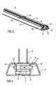
- FIG. 3 schematically a perspective view of the lower rail 2 is shown.
- the lower rail 2 comprises at least the rail profile 6 and two flange portions 11 arranged laterally therefrom.
- the rail profile 6 is substantially U-shaped and has in its side portions 12 a plurality of in the longitudinal direction of the rail profile 6 adjacent through holes 13.
- a holding and guiding element 15 is arranged.
- the two holding and guiding elements 15 are aligned facing each other and project beyond the side portion 12th
- a flange region 11 can be folded at the upper edge 14 and form the holding and guiding element 15.
- the holding and guiding element 15 may be formed as a separate component and arranged on the upper edge 14.
- each holding and guiding element 15 two recesses 16 are arranged at a distance from each other, which corresponds to a distance of the locking elements 9 in the upper rail 3.
- the recesses 16 of the two adjacent holding and guiding elements 15 are arranged opposite one another.
- the recesses 16 are formed such that they do not project beyond the side portion 12. For example, side portion 12 and recesses 16 are flush with each other.
- FIG. 4 is shown schematically a sectional view of the locking element 9 in the operating position.
- the locking elements 9 are held on their upper side 17 by the holding and guiding element 15 and the upper rail 3 is positively secured against separation from the lower rail. It is by means of this positive connection between upper rail 3 and lower rail 2 acting holding forces in the vertical direction transferable.
- a width of the locking element 9 is formed corresponding to an inner width of the rail profile 6.
- the locking element 9 is a locking bolt 18 in the vehicle transverse direction, thus arranged transversely to the orientation of the rail unit 1, slidably.
- a cross section of the locking bolt 18 is formed corresponding to the through holes 13 in the side portions 12 of the rail profile 6.
- the locking bolt 18 is arranged completely in the locking element 9 in a first position. In this position, the upper rail 3 is displaceable in the lower rail 2.
- the locking bolt 18 is displaced in the vehicle transverse direction such that it protrudes from the locking element 9 and is arranged in one of the through holes 13 in the side section 12 of the rail profile 6.
- the upper rail 3 is locked in the lower rail 2, so that any relative movement between the upper rail 3 and lower rail 2 is avoided.
- arranged on the upper rail 3 vehicle seat is not displaced and its position is secured against change.
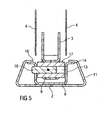
- FIG. 5 schematically is a sectional view of the locking element 9 shown in the removal position.
- the removal position is the position in which the locking elements 9 are located in the region of the recesses 16.
- not shown and not inventive embodiment eliminates the holding and guiding element 15 on the upper edge 14 of the rail profile 6.
- at least one further locking unit is arranged, which engages in the locked position below the upper edge 14 of the rail profile 6 and thus prevents lifting of the upper rail 3 of the lower rail 2.
- the lifting of the upper rail 3 from the lower rail 2 is made possible. Due to the further locking unit in the upper rail 3, a separation of the upper rail 3 and lower rail 2 at any point in the travel range of the rail unit 1 is made possible.
Landscapes
- Engineering & Computer Science (AREA)
- Aviation & Aerospace Engineering (AREA)
- Transportation (AREA)
- Mechanical Engineering (AREA)
- Seats For Vehicles (AREA)
Description
- Die Erfindung betrifft eine Längsverstellvorrichtung für einen Fahrzeugsitz mit trennbarer Ober- und Unterschiene gemäß dem Oberbegriff des Anspruchs 1 (s. zum Beispiel die
DE 200 19 891 U1 ). - Stand der Technik sind herkömmliche Längsverstellvorrichtungen für Fahrzeugsitze, welche eine Unter- und Oberschiene umfassen. Die Oberschiene ist in der Unterschiene angeordnet oder greift in diese ein, wobei die Oberschiene korrespondierend zur Unterschiene ausgeformt ist. Es ist nicht vorgesehen, dass die Oberschiene von der Unterschiene getrennt werden kann.
- Trennbare Längsverstellvorrichtungen sind beispielsweise aus der am 24.02.2011 offengelegten
DE 10 2009 038 126 A1 , der am 14.04.2011 offengelegtenDE 10 2009 048 498 A1 oder aus derEP 0 922 606 A1 bekannt. - Verschiebbare und entnehmbare oder verschiebbare und kippbare Fahrzeugsitze weisen im Stand der Technik eine Schieneneinheit aus Unter- und Oberschiene und eine separate Trennvorrichtung auf. Diese Trennvorrichtung bildet eine von der Schieneneinheit separierte Trennstelle zwischen Schieneneinheit und Fahrzeugsitz.
- Weiterhin beschreibt die o.g.
DE 200 19 891 U1 eine Vorrichtung zum zeitweiligen Verbinden eines bewegbaren Fahrzeugsitzes mit einer eine hinterschnittene Längsnut aufweisenden Halteschiene, in deren Kopfwand in Abständen zueinander Bohrungen eingebracht sind, deren Durchmesser größer ist als der Abstand der die hinterschnittenen Bereiche der Längsnut übergreifenden Formrippen voneinander ist. Von einem Stabelement der Vorrichtung ragen in Abstand zueinander wenigstens zwei in die Längsnut einsetzbare Verbindungselemente ab, die jeweils mit einem Kragorgan versehen sind, das in den hinterschnittenen Bereich der Halteschiene einschiebbar ausgebildet ist. In ein Hohlprofil der Vorrichtung sind in Abstand zueinander zwei den freien Profilquerschnitt ausfüllende Lagerblöcke als Halteorgane für das an der Profilaußenseite angeordnete Kragorgan eingebracht, wobei zwischen den Lagerblöcken das Hohlprofil von einem quer zur Profillängsachse bewegbaren sowie in eine Bohrung der Halteschiene einsetzbar gestalteten Bolzen durchsetzt ist. - Die
FR 2 864 481 A1 - Aufgabe der vorliegenden Erfindung ist es, eine gegenüber dem Stand der Technik verbesserte und insbesondere flexibler nutzbare und leichtere Längsverstellvorrichtung für einen Fahrzeugsitz mit trennbarer Ober- und Unterschiene anzugeben.
- Hinsichtlich der Längsverstellvorrichtung wird die Aufgabe durch die im Anspruch 1 angegebenen Merkmale gelöst.
- Vorteilhafte Weiterbildungen der Erfindung sind Gegenstand der Unteransprüche.
- Bei der Längsverstellvorrichtung für einen Fahrzeugsitz, welche eine Unterschiene und Oberschiene umfasst, wobei die Oberschiene längsverschiebbar in der Unterschiene angeordnet ist, steht die Oberschiene mit der Unterschiene in Eingriff, wobei an einer Oberkante der Unterschiene ein Halte- und Führungselement ausgebildet, angeformt oder angeordnet ist, welches die Oberschiene in Betriebsposition an der Unterschiene hält. Erfindungsgemäß sind in der Oberschiene zumindest zwei Verriegelungselemente angeordnet und/oder integriert, nach deren Entriegelung die Oberschiene und ein daran befestigter Fahrzeugsitz in einer vorgegebenen Position von der Unterschiene trennbar sind. Somit ist ein Fahrzeugsitz auf einfache Weise aus dem Fahrzeug entnehmbar. Die Unterschiene umfasst dabei zumindest das Schienenprofil und zwei seitlich davon angeordnete Flanschbereiche, wobei die Flanschbereiche Durchgangslöcher im Seitenabschnitt des Schienenprofils abdecken und somit eine Verletzungsgefahr für die Fahrzeuginsassen minimieren.
- Im Vergleich zum Stand der Technik ist eine separate Trennvorrichtung zwischen Schieneneinheit und Fahrzeugsitz vermieden, welche teurer und schwerer ist sowie mehr Bauraum benötigt.
- Besonders vorteilhafterweise wird bei der Erfindung ein einfaches und kostengünstiges Design für die Unterschiene ermöglicht. Dadurch kann eine Längsverstellvorrichtung mit besonders großem Verstellweg direkt an oder in eine Fahrzeugkarosserie integriert werden.
- Vorteilhafterweise sind zwischen Oberschiene und Unterschiene wirkende Haltekräfte in horizontaler Längsrichtung und in vertikaler Richtung mittels einer durch die Verriegelungselemente gebildeten formschlüssigen Verbindung übertragbar.
- Besonders vorteilhafterweise sind zwischen Oberschiene und Unterschiene wirkende Haltekräfte in vertikaler Richtung mittels einer durch das oberseitig zumindest auf die Verriegelungselemente einwirkende Halte- und Führungselement gebildeten formschlüssigen Verbindung übertragbar.
- In einer vorteilhaften Ausführungsform ist in der Unterschiene eine Mehrzahl von Aussparungen angeordnet, so dass die Oberschiene in zumindest einer von den Aussparungen vorgegebenen Position von der Unterschiene trennbar ist.
- Zweckmäßigerweise sind im Seitenabschnitt des Schienenprofils der Unterschiene eine Mehrzahl von Durchgangslöchern ausgebildet, welche in Längsrichtung der Unterschiene nebeneinander angeordnet und eine besonders fein abgestufte Arretierung der Oberschiene in Bezug auf die Unterschiene ermöglichen.
- In einer weiteren vorteilhaften Ausführungsform ist ein in der Unterschiene angeordneter unterer Bereich der Oberschiene korrespondierend zu einem aufnehmenden Schienenprofil in der Unterschiene ausgeformt. Dadurch ist eine spielminimierte oder spielfreie Bewegung der Oberschiene relativ zur Unterschiene ermöglicht.
- Zweckmäßigerweise ist in einem vorderen Endbereich und in einem hinteren Endbereich der Oberschiene jeweils ein Verriegelungselement angeordnet.
- In einer weiteren vorteilhaften Ausführungsform ist an einer Oberkante der Unterschiene ein Halte- und Führungselement ausgebildet, angeformt oder angeordnet, welches die Oberschiene in Betriebsposition an der Unterschiene hält.
- In jedem Halte- und Führungselement sind bevorzugt zwei Aussparungen in einem Abstand zueinander angeordnet, welcher mit einem Abstand der Verriegelungselemente in der Oberschiene korrespondiert. Somit ist mittels der Aussparungen die Position vorgegeben, in welcher die Oberschiene von der Unterschiene abgehoben werden kann.
- Im Verriegelungselement ist besonders bevorzugt ein Verriegelungsbolzen quer zur Ausrichtung von Unterschiene und Oberschiene verschiebbar angeordnet, wobei ein Querschnitt des Verriegelungsbolzens korrespondierend zu den Durchgangslöchern, welche in den Seitenabschnitten des Schienenprofils angeordnet sind, ausgeformt ist. Dadurch können Unterschiene und Oberschiene relativ zueinander arretiert werden, so dass eine Bewegung zwischen Unterschiene und Oberschiene verhindert ist.
- An der Oberschiene sind bevorzugt zumindest zwei Rollenelemente derart drehbar angeordnet oder integriert, dass sie die Oberschiene unterseitig zumindest abschnittsweise überragen, so dass die Rollenelemente in Betriebsposition der Oberschiene im Schienenprofil der Unterschiene abrollen. Dadurch ist eine besonders reibungsminimierte und kraftreduzierte Bewegung der Oberschiene relativ zur Unterschiene ermöglicht.
- In einer alternativen Ausführungsform ist in der Oberschiene zumindest eine weitere Verriegelungseinheit angeordnet, welche in verriegelter Position unter eine Oberkante des Schienenprofils greift und ein Abheben der Oberschiene von der Unterschiene verhindert und in entriegelter Position ein Abheben der Oberschiene von der Unterschiene ermöglicht. Somit ist die Oberschiene in jeder Position von der Unterschiene trennbar.
- Die beiden Halte- und Führungselemente sind bevorzugt aufeinander zuweisend ausgerichtet und überragen den Seitenabschnitt des Schienenprofils der Unterschiene. Somit sind die Verriegelungselemente in Betriebsposition der Oberschiene von den Halte- und Führungselementen formschlüssig gehalten und die Oberschiene ist gegen ein vertikales Abheben von der Unterschiene gesichert.
- Besonders bevorzugter Weise ist der Flanschbereich an seiner Oberkante abgekantet und bildet derart das oder die Halte- und Führungselemente aus. Dadurch ist eine besonders einfache und effiziente Herstellung der Unterschiene ermöglicht, welche bevorzugter Weise aus zwei miteinander verbundenen Blechprägeteilen besteht.
- Anhand der beigefügten schematischen Figuren wird die Erfindung näher erläutert.
- Dabei zeigen:
- Figur 1
- schematisch eine perspektivische Ansicht einer Schieneneinheit,
- Figur 2
- schematisch eine perspektivische Ansicht einer Oberschiene,
- Figur 3
- schematisch eine perspektivische Ansicht einer Unterschiene,
- Figur 4
- schematisch eine Schnittdarstellung eines Verriegelungselementes in Betriebsposition und
- Figur 5
- schematisch eine Schnittdarstellung eines Verriegelungselementes in Entnahmeposition.
- Einander entsprechende Teile sind in allen Figuren mit den gleichen Bezugszeichen versehen.
- In
Figur 1 ist schematisch eine perspektivische Ansicht einer Schieneneinheit 1 dargestellt. Eine solche Schieneneinheit 1 umfasst eine Unterschiene 2 und eine Oberschiene 3. - Die Unterschiene 2 ist in herkömmlicher und nicht dargestellter Weise an einem Fahrzeugboden eines Fahrzeugs befestigt und vorzugsweise in Längsrichtung des Fahrzeugs ausgerichtet.
- An der Oberschiene 3 ist ein herkömmlicher Fahrzeugsitz angeordnet, von welchem ein Rahmenelement 4 dargestellt ist. Durch eine Längsverschiebung der Oberschiene 3 relativ zur Unterschiene 2 ist somit der Fahrzeugsitz im Fahrzeug verschiebbar.
- In der in
Figur 1 dargestellten Betriebsposition der Schieneneinheit 1 ist die Oberschiene 3 längsverschiebbar zumindest bereichsweise in der Unterschiene 2 angeordnet. - Ein in der Unterschiene 2 angeordneter unterer Bereich 5 der Oberschiene 3 ist korrespondierend zu dem aufnehmenden Schienenprofil 6 in der Unterschiene 2 ausgeformt.
- In
Figur 2 ist schematisch eine perspektivische Ansicht der Oberschiene 3 mit daran angeordnetem Rahmenelement 4 dargestellt. - In einem vorderen Endbereich 7 und in einem hinteren Endbereich 8 der Oberschiene 3 ist jeweils ein Verriegelungselement 9 angeordnet.
- Die Verriegelungselemente 9 sind im unteren Bereich 5 der Oberschiene 3 angeordnet und in Betriebsposition der Schieneneinheit 1 im Schienenprofil 6 der Unterschiene 2 innenliegend angeordnet.
- Zwischen den Verriegelungselementen 9 sind im unteren Bereich 5 der Oberschiene 3 zumindest zwei herkömmliche Rollenelemente 10 drehbar angeordnet. Diese Rollenelemente 10 rollen im Schienenprofil 6 der Unterschiene 2 und ermöglichen dadurch eine reibungsminimierte und kraftreduzierte Bewegung der Oberschiene 3 relativ zur Unterschiene 2.
- In einer alternativen, nicht dargestellten Ausführungsform sind an Stelle der Rollenelemente 10 herkömmliche Gleitelemente, beispielsweise aus einem reibungsreduzierten Kunststoff, anordenbar
- In einer weiteren alternativen, nicht dargestellten Ausführungsform können die Rollenelemente 10 auf einem Flanschbereich 11 der Unterschiene 2 rollen.
- In
Figur 3 ist schematisch eine perspektivische Ansicht der Unterschiene 2 dargestellt. - Die Unterschiene 2 umfasst zumindest das Schienenprofil 6 und zwei seitlich davon angeordnete Flanschbereiche 11.
- Das Schienenprofil 6 ist im Wesentlichen u-förmig ausgebildet und weist in seinen Seitenabschnitten 12 eine Vielzahl von in Längsrichtung des Schienenprofils 6 nebeneinander angeordneten Durchgangslöchern 13 auf.
- An einer Oberkante 14 jedes Seitenabschnitts 12 des Schienenprofils 6 ist ein Halte- und Führungselement 15 angeordnet.
- Die beiden Halte- und Führungselemente 15 sind aufeinander zuweisend ausgerichtet und überragen den Seitenabschnitt 12.
- Insbesondere kann ein Flanschbereich 11 an der Oberkante 14 abgekantet sein und das Halte- und Führungselement 15 ausbilden.
- In einer nicht dargestellten Ausführungsvariante kann das Halte- und Führungselement 15 als separates Bauteil ausgebildet und an der Oberkante 14 angeordnet sein.
- In jedem Halte- und Führungselement 15 sind zwei Aussparungen 16 in einem Abstand zueinander angeordnet, welcher mit einem Abstand der Verriegelungselemente 9 in der Oberschiene 3 korrespondiert.
- Die Aussparungen 16 der beiden benachbarten Halte- und Führungselemente 15 sind einander gegenüberliegend angeordnet.
- Die Aussparungen 16 sind derart ausgeformt, dass sie den Seitenabschnitt 12 nicht überragen. Beispielsweise schließen Seitenabschnitt 12 und Aussparungen 16 bündig miteinander ab.
- In
Figur 4 ist schematisch eine Schnittdarstellung des Verriegelungselements 9 in Betriebsposition dargestellt. - Als Betriebsposition wird eine Position bezeichnet, in welcher die Oberschiene 3 verschiebbar in der Unterschiene 2 angeordnet ist, wobei sich die Verriegelungselemente 9 nicht im Bereich der Aussparungen 16 befinden.
- Dadurch sind die Verriegelungselemente 9 an ihrer Oberseite 17 vom Halte- und Führungselement 15 gehalten und die Oberschiene 3 ist formschlüssig gegen ein Trennen von der Unterschiene gesichert. Dabei sind mittels dieser formschlüssigen Verbindung zwischen Oberschiene 3 und Unterschiene 2 wirkende Haltekräfte in vertikaler Richtung übertragbar.
- Eine Breite des Verriegelungselements 9 ist korrespondierend zu einer Innenbreite des Schienenprofils 6 ausgeformt.
- Im Verriegelungselement 9 ist ein Verriegelungsbolzen 18 in Fahrzeugquerrichtung, mithin quer zur Ausrichtung der Schieneneinheit 1, verschiebbar angeordnet.
- Ein Querschnitt des Verriegelungsbolzens 18 ist korrespondierend zu den Durchgangslöchern 13 in den Seitenabschnitten 12 des Schienenprofils 6 ausgeformt.
- Im Betrieb des Verriegelungselements 9 ist der Verriegelungsbolzen 18 in einer ersten Position vollständig im Verriegelungselement 9 angeordnet. In dieser Position ist die Oberschiene 3 in der Unterschiene 2 verschiebbar.
- In einer zweiten Position wird der Verriegelungsbolzen 18 derart in Fahrzeugquerrichtung verschoben, dass er aus dem Verriegelungselement 9 herausragt und in einem der Durchgangslöcher 13 im Seitenabschnitt 12 des Schienenprofils 6 angeordnet ist. In dieser Position ist die Oberschiene 3 in der Unterschiene 2 arretiert, so dass jegliche Relativbewegung zwischen Oberschiene 3 und Unterschiene 2 vermieden ist. Daraus resultierend ist der an der Oberschiene 3 angeordnete Fahrzeugsitz nicht verschiebbar und seine Position ist gegen eine Veränderung gesichert.
- In
Figur 5 ist schematisch eine Schnittdarstellung des Verriegelungselements 9 in Entnahmeposition dargestellt. - Als Entnahmeposition wird die Position bezeichnet, in welcher sich die Verriegelungselemente 9 im Bereich der Aussparungen 16 befinden.
- In dieser Position sind die Verriegelungselemente 9 an ihrer Oberseite 17 nicht vom Halte- und Führungselement 15 gehalten. Dadurch ist die Oberschiene 3 mit dem daran angeordneten Fahrzeugsitz nach Lösen des Verriegelungsbolzens 18 nach oben aus der Unterschiene 2 und somit aus dem Fahrzeug entnehmbar.
- In einer alternativen, nicht dargestellten und nicht erfindungsgemäßen Ausführungsform entfällt das Halte- und Führungselement 15 auf der Oberkante 14 des Schienenprofils 6. In der Oberschiene 3 ist zumindest eine weitere Verriegelungseinheit angeordnet, welche in verriegelter Position unter die Oberkante 14 des Schienenprofils 6 greift und somit ein Abheben der Oberschiene 3 von der Unterschiene 2 verhindert. In entriegelter Position der weiteren Verriegelungseinheit ist das Abheben der Oberschiene 3 von der Unterschiene 2 ermöglicht. Durch die weitere Verriegelungseinheit in der Oberschiene 3 ist eine Trennung von Oberschiene 3 und Unterschiene 2 an jeder Stelle im Verfahrbereich der Schieneneinheit 1 ermöglicht.
-
- 1
- Schieneneinheit
- 2
- Unterschiene
- 3
- Oberschiene
- 4
- Rahmenelement
- 5
- unterer Bereich
- 6
- Schienenprofil
- 7
- vorderer Endbereich
- 8
- hinterer Endbereich
- 9
- Verriegelungselement
- 10
- Rollenelemente
- 11
- Flanschbereich
- 12
- Seitenabschnitt
- 13
- Durchgangsloch
- 14
- Oberkante
- 15
- Halte- und Führungselement
- 16
- Aussparung
- 17
- Oberseite
- 18
- Verriegelungsbolzen
Claims (14)
- Längsverstellvorrichtung für einen Fahrzeugsitz, welche eine Unterschiene (2) und Oberschiene (3) umfasst, wobei die Oberschiene (3) längsverschiebbar in der Unterschiene (2) angeordnet ist, wobei die Oberschiene (3) mit der Unterschiene (2) in Eingriff steht, wobei an einer Oberkante (14) der Unterschiene (2) ein Halte- und Führungselement (15) ausgebildet, angeformt oder angeordnet ist, welches die Oberschiene (3) in Betriebsposition an der Unterschiene (2) hält,
dadurch gekennzeichnet, dass in der Oberschiene (3) zumindest zwei Verriegelungselemente (9) angeordnet und/oder integriert sind, nach deren Entriegelung die Oberschiene (3) und ein daran befestigter Fahrzeugsitz in einer vorgegebenen Position von der Unterschiene (2) trennbar sind, wobei die Unterschiene (2) zumindest ein Schienenprofil (6) und zwei seitlich davon angeordnete Flanschbereiche (11) umfasst, die in Seitenabschnitten (12) des Schienenprofils (6) angeordnete Durchgangslöcher (13) abdecken. - Längsverstellvorrichtung nach Anspruch 1,
dadurch gekennzeichnet, dass zwischen Oberschiene (3) und Unterschiene (2) wirkende Haltekräfte in horizontaler Längsrichtung und in vertikaler Richtung mittels einer durch die Verriegelungselemente (9) gebildeten formschlüssigen Verbindung übertragbar sind. - Längsverstellvorrichtung nach Anspruch 1 oder 2,
dadurch gekennzeichnet, dass zwischen Oberschiene (3) und Unterschiene (2) wirkende Haltekräfte in vertikaler Richtung mittels einer durch das oberseitig zumindest auf die Verriegelungselemente (9) einwirkende Halte- und Führungselement (15) gebildeten formschlüssigen Verbindung übertragbar sind. - Längsverstellvorrichtung nach einem der vorherigen Ansprüche,
dadurch gekennzeichnet, dass in der Unterschiene (2) eine Mehrzahl von Aussparungen (16) angeordnet ist, so dass die Oberschiene (3) in zumindest einer von den Aussparungen (16) vorgegebenen Position von der Unterschiene (2) trennbar ist. - Längsverstellvorrichtung nach einem der vorherigen Ansprüche,
dadurch gekennzeichnet, dass im Seitenabschnitt (12) des Schienenprofils (6) der Unterschiene (2) eine Mehrzahl von Durchgangslöchern (13) ausgebildet ist, welche in Längsrichtung der Unterschiene (2) nebeneinander angeordnet sind. - Längsverstellvorrichtung nach einem der vorherigen Ansprüche,
dadurch gekennzeichnet, dass ein in der Unterschiene (2) angeordneter unterer Bereich (5) der Oberschiene (3) korrespondierend zu einem aufnehmenden Schienenprofil (6) in der Unterschiene (2) ausgeformt ist. - Längsverstellvorrichtung nach einem der vorherigen Ansprüche,
dadurch gekennzeichnet, dass in einem vorderen Endbereich (7) und in einem hinteren Endbereich (8) der Oberschiene (3) jeweils ein Verriegelungselement (9) angeordnet ist. - Längsverstellvorrichtung nach Anspruch 7,
dadurch gekennzeichnet, dass in jedem Halte- und Führungselement (15) zwei Aussparungen (16) in einem Abstand zueinander angeordnet sind, welcher mit einem Abstand der Verriegelungselemente (9) in der Oberschiene (3) korrespondiert. - Längsverstellvorrichtung nach einem der Ansprüche 4 bis 8,
dadurch gekennzeichnet, dass in dem jeweiligen Verriegelungselement (9) ein Verriegelungsbolzen (18) quer zur Ausrichtung von Unterschiene (2) und Oberschiene (3) verschiebbar angeordnet ist, wobei ein Querschnitt des Verriegelungsbolzens (18) korrespondierend zu den Durchgangslöchern (13) ausgeformt ist. - Längsverstellvorrichtung nach einem der vorherigen Ansprüche,
dadurch gekennzeichnet, dass an der Oberschiene (3) zumindest zwei Rollenelemente (10) derart drehbar angeordnet oder integriert sind, dass sie die Oberschiene (3) unterseitig zumindest abschnittsweise überragen. - Längsverstellvorrichtung nach Anspruch 10,
dadurch gekennzeichnet, dass die Rollenelemente (10) in Betriebsposition der Oberschiene (3) im Schienenprofil (6) der Unterschiene (2) abrollen. - Längsverstellvorrichtung nach einem der vorherigen Ansprüche,
dadurch gekennzeichnet, dass in der Oberschiene (3) zumindest eine weitere Verriegelungseinheit angeordnet ist, welche in verriegelter Position unter die Oberkante (14) des Schienenprofils (6) greift und ein Abheben der Oberschiene (3) von der Unterschiene (2) verhindert und in entriegelter Position ein Abheben der Oberschiene (3) von der Unterschiene (2) ermöglicht. - Längsverstellvorrichtung nach einem der vorherigen Ansprüche,
dadurch gekennzeichnet, dass die beiden Halte- und Führungselemente (15) aufeinander zuweisend ausgerichtet sind und den Seitenabschnitt (12) des Schienenprofils (6) der Unterschiene (2) überragen. - Längsverstellvorrichtung nach einem der vorherigen Ansprüche,
dadurch gekennzeichnet, dass der Flanschbereich (11) an der Oberkante (14) abgekantet ist und derart das Halte- und Führungselement (15) ausbildet.
Priority Applications (1)
| Application Number | Priority Date | Filing Date | Title |
|---|---|---|---|
| PL11749161T PL2608982T3 (pl) | 2010-08-23 | 2011-08-23 | Urządzenie do regulacji wzdłużnej siedzenia samochodowego z odłączaną górną i dolną szyną |
Applications Claiming Priority (3)
| Application Number | Priority Date | Filing Date | Title |
|---|---|---|---|
| DE102010035157 | 2010-08-23 | ||
| DE102010063615.0A DE102010063615B4 (de) | 2010-08-23 | 2010-12-21 | Längsverstellvorrichtung für einen Fahrzeugsitz mit trennbarer Ober- und Unterschiene |
| PCT/EP2011/064490 WO2012025539A1 (de) | 2010-08-23 | 2011-08-23 | Längsverstellvorrichtung für einen fahrzeugsitz mit trennbarer ober- und unterschiene |
Publications (2)
| Publication Number | Publication Date |
|---|---|
| EP2608982A1 EP2608982A1 (de) | 2013-07-03 |
| EP2608982B1 true EP2608982B1 (de) | 2014-06-04 |
Family
ID=44514734
Family Applications (1)
| Application Number | Title | Priority Date | Filing Date |
|---|---|---|---|
| EP11749161.3A Active EP2608982B1 (de) | 2010-08-23 | 2011-08-23 | Längsverstellvorrichtung für einen fahrzeugsitz mit trennbarer ober- und unterschiene |
Country Status (8)
| Country | Link |
|---|---|
| US (1) | US9701217B2 (de) |
| EP (1) | EP2608982B1 (de) |
| JP (1) | JP5663663B2 (de) |
| KR (1) | KR101411603B1 (de) |
| CN (1) | CN103068621B (de) |
| DE (1) | DE102010063615B4 (de) |
| PL (1) | PL2608982T3 (de) |
| WO (1) | WO2012025539A1 (de) |
Families Citing this family (39)
| Publication number | Priority date | Publication date | Assignee | Title |
|---|---|---|---|---|
| US9599138B2 (en) * | 2012-03-28 | 2017-03-21 | B/E Aerospace, Inc. | Aircraft monument integrated attachment device |
| DE102013205995A1 (de) * | 2013-04-04 | 2014-10-09 | Siemens Aktiengesellschaft | Befestigungsanordnung für ein Innenausstattungselement am Wagenkasten eines Fahrzeugs |
| DE102013107083B4 (de) | 2013-07-05 | 2021-07-08 | allsafe GmbH & Co.KG | Vorrichtung zum Festlegen eines Gegenstandes |
| JP6264075B2 (ja) * | 2013-07-30 | 2018-01-24 | アイシン精機株式会社 | 車両用シートスライド装置 |
| DE102016113409B4 (de) * | 2015-10-02 | 2022-06-30 | Tillmann Profil Gmbh | Schiene für einen Sitz eines Kraftfahrzeuges sowie Sitzschienensystem für ein Kraftfahrzeug |
| DE102016107306B4 (de) * | 2016-04-20 | 2022-12-22 | allsafe GmbH & Co.KG | System umfassend ein Führungsmittel und eine Schiene zur Aufnahme eines Führungsmittels |
| DE102017113899B4 (de) | 2017-06-22 | 2023-01-05 | allsafe GmbH & Co.KG | Führungsmittel zum Festlegen eines Gegenstandes in einer Schiene, System umfassend ein solches Führungsmittel und eine Schiene zur Aufnahme eines Führungsmittels, sowie Verfahren zur Herstellung des Führungsmittels |
| GB2578857B (en) * | 2017-06-26 | 2021-12-29 | Jaguar Land Rover Ltd | Mounting assembly for a vehicle |
| GB2563843B (en) * | 2017-06-26 | 2020-04-01 | Jaguar Land Rover Ltd | Mounting assembly for a vehicle |
| US12233756B2 (en) | 2018-05-04 | 2025-02-25 | Lear Corporation | Track system with a support member |
| US11040638B2 (en) | 2018-05-04 | 2021-06-22 | Lear Corporation | Track assembly |
| US11040639B2 (en) | 2018-05-04 | 2021-06-22 | Lear Corporation | Track assembly |
| FR3080806B1 (fr) * | 2018-05-04 | 2020-11-27 | Lear Corp | Module d'ancrage d'un equipement automobile, glissiere d'ancrage et ensemble d'ancrage |
| DE102019206304B4 (de) * | 2018-05-04 | 2022-01-27 | Lear Corporation | Schienenanordnung |
| US10562414B2 (en) | 2018-05-04 | 2020-02-18 | Lear Corporation | Track assembly |
| US10882420B2 (en) | 2019-03-08 | 2021-01-05 | Lear Corporation | Track assembly |
| US11358497B2 (en) | 2018-05-04 | 2022-06-14 | Lear Corporation | Track system having a rolling member |
| US10906431B2 (en) | 2018-05-04 | 2021-02-02 | Lear Corporation | Track assembly |
| US10926667B2 (en) | 2018-05-04 | 2021-02-23 | Lear Corporation | Track assembly |
| US11440482B2 (en) | 2018-12-10 | 2022-09-13 | Lear Corporation | Track assembly |
| US11225201B2 (en) | 2018-12-10 | 2022-01-18 | Lear Corporation | Track assembly |
| US11117538B2 (en) | 2018-12-17 | 2021-09-14 | Lear Corporation | Electrical assembly |
| US10855037B2 (en) | 2018-12-17 | 2020-12-01 | Lear Corporation | Support assembly with a support member and a track assembly |
| US11613220B2 (en) | 2018-12-17 | 2023-03-28 | Lear Corporation | Electrical assembly |
| US10950977B2 (en) | 2018-12-18 | 2021-03-16 | Lear Corporation | Track assembly for a vehicle component |
| US11975665B2 (en) | 2019-02-20 | 2024-05-07 | Lear Corporation | Electrical assembly |
| US11040653B2 (en) | 2019-02-25 | 2021-06-22 | Lear Corporation | Track assembly |
| US11299075B2 (en) | 2019-03-06 | 2022-04-12 | Lear Corporation | Electrical assembly |
| US11807142B2 (en) | 2019-03-06 | 2023-11-07 | Lear Corporation | Electrical track assembly |
| JP7211248B2 (ja) * | 2019-04-23 | 2023-01-24 | トヨタ紡織株式会社 | スライド装置 |
| US11463083B2 (en) | 2019-10-04 | 2022-10-04 | Lear Corporation | Electrical system |
| US11634101B2 (en) | 2019-10-04 | 2023-04-25 | Lear Corporation | Removable component system |
| US11323114B2 (en) | 2019-10-04 | 2022-05-03 | Lear Corporation | Electrical system |
| US11584259B2 (en) | 2020-01-17 | 2023-02-21 | The Boeing Company | Seat fittings for attaching seats to seat tracks in a vehicle and related systems and methods |
| US11906028B2 (en) | 2020-02-21 | 2024-02-20 | Lear Corporation | Track system with a support member |
| DE102021104018B4 (de) | 2020-02-21 | 2023-11-09 | Lear Corporation | Schienensystem mit einem Stützelement, Verfahren zum Betreiben eines Schienensystems |
| US11505141B2 (en) | 2020-10-23 | 2022-11-22 | Lear Corporation | Electrical system with track assembly and support assembly |
| DE102021108767A1 (de) | 2021-04-08 | 2022-10-13 | Sitech Sitztechnik Gmbh | Sitzschiene |
| KR20230048752A (ko) | 2021-10-05 | 2023-04-12 | 현대자동차주식회사 | 모빌리티 시트 시스템 및 차량 |
Family Cites Families (38)
| Publication number | Priority date | Publication date | Assignee | Title |
|---|---|---|---|---|
| US2277947A (en) * | 1940-05-23 | 1942-03-31 | American Forging & Socket Co | Adjustable support and locking mechanism |
| US4496271A (en) * | 1982-09-30 | 1985-01-29 | East/West Industries, Inc. | Restraining fittings |
| US4511187A (en) * | 1983-11-25 | 1985-04-16 | General Motors Corporation | Bearing assembly for seat slide |
| JPS6328743A (ja) * | 1986-07-23 | 1988-02-06 | Oi Seisakusho Co Ltd | 自動車用シ−トスライド装置 |
| JPH0545538Y2 (de) * | 1987-09-29 | 1993-11-22 | ||
| US4881827A (en) * | 1988-03-02 | 1989-11-21 | General Motors Corporation | Apparatus and method of anti-ratcheting vehicle seat adjuster slide |
| JPH0636995Y2 (ja) * | 1988-03-24 | 1994-09-28 | アイシン精機株式会社 | シートレール |
| JPH03121125U (de) * | 1990-03-27 | 1991-12-11 | ||
| JPH0455425U (de) * | 1990-09-20 | 1992-05-12 | ||
| US5222814A (en) * | 1992-09-30 | 1993-06-29 | Rockwell International Corporation | Vehicle seat track assembly |
| FR2772316B1 (fr) | 1997-12-12 | 2000-03-03 | Peugeot | Agencement de siege amovible et reglable en position longitudinale dans un habitacle de vehicule automobile |
| FR2777049B1 (fr) | 1998-04-06 | 2000-06-02 | Renault | Systeme d'arrimage modulable a commande par cames |
| JP3771376B2 (ja) * | 1998-06-16 | 2006-04-26 | シロキ工業株式会社 | 脱着シート |
| WO2001028807A1 (en) * | 1999-10-19 | 2001-04-26 | Magna Seating Systems Inc. | Seat track assembly having a locking mechanism with infinite engagement |
| US6260813B1 (en) * | 2000-01-10 | 2001-07-17 | November Whiskey, Inc. | Aircraft seat track anchor fitting |
| FR2812251B1 (fr) * | 2000-07-27 | 2003-01-03 | Antolin Grupo Ing Sa | Dispositif de guidage et d'ancrage pour siege amovible de vehicule |
| DE20019891U1 (de) | 2000-11-22 | 2001-05-03 | ANCRA Jungfalk GmbH & Co. KG, 78234 Engen | Vorrichtung zum zeitweiligen Verbinden eines bewegbaren Gegenstandes mit einer Halteschiene |
| DE10139630A1 (de) * | 2001-08-11 | 2003-03-06 | Keiper Gmbh & Co | Verriegelungsvorrichtung für einen Fahrzeugsitz |
| EP1316466B1 (de) * | 2001-11-28 | 2008-01-30 | C.Rob. Hammerstein GmbH & Co.KG | Arretiervorrichtung mit mehreren Sperrstiften |
| DE20211090U1 (de) * | 2002-07-23 | 2002-09-19 | KEIPER GmbH & Co., 67657 Kaiserslautern | Längseinsteller für einen Fahrzeugsitz |
| US6869057B2 (en) * | 2002-12-20 | 2005-03-22 | Fuji Kiko Co., Ltd. | Seat slide device |
| KR100512888B1 (ko) * | 2003-04-17 | 2005-09-07 | 주식회사 오스템 | 차량용 시이트이송트랙 |
| KR100512889B1 (ko) | 2003-05-27 | 2005-09-07 | 주식회사 오스템 | 차량용 시이트이송트랙의 록킹장치 |
| FR2864481B1 (fr) * | 2003-12-26 | 2006-04-07 | Renault Sas | Agencement pour le montage d'un siege sur le plancher d'un vehicule au moyen de plots de guidage escamotables |
| DE202005012828U1 (de) | 2005-05-10 | 2006-02-09 | Allsafe Jungfalk Gmbh & Co. Kg | Vorrichtung zum Verankern einer Sitzeinrichtung an einem Fahrzeugboden |
| DE202005020672U1 (de) | 2005-05-19 | 2006-06-08 | Keiper Gmbh & Co.Kg | Fahrzeugsitz, insbesondere Kraftfahrzeugsitz |
| JP4434075B2 (ja) * | 2005-05-20 | 2010-03-17 | トヨタ紡織株式会社 | 車両用シートの移動装置 |
| DE102005032437A1 (de) * | 2005-07-09 | 2007-01-11 | Webasto Ag | Fahrzeugdach mit einem bewegbaren Dachteil |
| DK1892142T3 (da) * | 2006-08-23 | 2011-02-21 | Martech Holding As | Monteringsindretning |
| CN101524970B (zh) | 2008-03-05 | 2013-03-20 | C.劳勃.汉默斯坦两合有限公司 | 用于沿纵向可调且可拆卸的机动车座椅的纵向引导装置 |
| US8052112B2 (en) * | 2008-03-13 | 2011-11-08 | GM Global Technology Operations LLC | Fore-aft position adjuster utilizing active material actuation |
| CH701264B1 (de) | 2009-06-12 | 2013-11-29 | Allsafe Jungfalk Gmbh & Co Kg | Vorrichtung zur Festlegung eines Gegenstandes. |
| CA2765202A1 (en) * | 2009-06-23 | 2011-01-13 | Weber Aircraft Llc | Seat track fitting |
| DE102009038126B4 (de) | 2009-08-11 | 2018-12-13 | Adient Luxembourg Holding S.À R.L. | Längseinsteller für einen Fahrzeugsitz |
| JP5512194B2 (ja) * | 2009-08-20 | 2014-06-04 | トヨタ紡織株式会社 | 車両用シート |
| DE102009048498A1 (de) | 2009-09-29 | 2011-04-14 | Daimler Ag | Längseinsteller für einen Fahrzeugsitz oder dergleichen |
| JP5654764B2 (ja) * | 2010-03-26 | 2015-01-14 | 富士重工業株式会社 | 車両用シートのスライド装置 |
| JP5845962B2 (ja) * | 2012-02-21 | 2016-01-20 | アイシン精機株式会社 | 車両用シートスライド装置 |
-
2010
- 2010-12-21 DE DE102010063615.0A patent/DE102010063615B4/de active Active
-
2011
- 2011-08-23 WO PCT/EP2011/064490 patent/WO2012025539A1/de not_active Ceased
- 2011-08-23 JP JP2013524462A patent/JP5663663B2/ja not_active Expired - Fee Related
- 2011-08-23 CN CN201180040654.1A patent/CN103068621B/zh active Active
- 2011-08-23 KR KR1020137007197A patent/KR101411603B1/ko not_active Expired - Fee Related
- 2011-08-23 PL PL11749161T patent/PL2608982T3/pl unknown
- 2011-08-23 EP EP11749161.3A patent/EP2608982B1/de active Active
- 2011-08-23 US US13/818,516 patent/US9701217B2/en active Active
Also Published As
| Publication number | Publication date |
|---|---|
| CN103068621A (zh) | 2013-04-24 |
| PL2608982T3 (pl) | 2014-10-31 |
| DE102010063615A1 (de) | 2012-02-23 |
| KR101411603B1 (ko) | 2014-06-25 |
| DE102010063615B4 (de) | 2021-07-22 |
| US20130206953A1 (en) | 2013-08-15 |
| WO2012025539A1 (de) | 2012-03-01 |
| JP5663663B2 (ja) | 2015-02-04 |
| CN103068621B (zh) | 2016-05-11 |
| US9701217B2 (en) | 2017-07-11 |
| KR20130043233A (ko) | 2013-04-29 |
| EP2608982A1 (de) | 2013-07-03 |
| JP2013534193A (ja) | 2013-09-02 |
Similar Documents
| Publication | Publication Date | Title |
|---|---|---|
| EP2608982A1 (de) | Längsverstellvorrichtung für einen fahrzeugsitz mit trennbarer ober- und unterschiene | |
| EP3478533B1 (de) | Längseinsteller sowie fahrzeugsitz | |
| DE102011108652B4 (de) | Fahrzeugsitz, insbesondere Kraftfahrzeugsitz | |
| EP2188147A1 (de) | Befestigungsbeschlag | |
| DE3538438A1 (de) | Verstellbare befestigungseinrichtung | |
| EP3150426A1 (de) | Schiene für einen sitz eines kraftfahrzeuges sowie sitzschienensystem für ein kraftfahrzeug | |
| DE202018102084U1 (de) | Vorrichtung zur Bewegung eines an einem Möbelkorpus eines Möbels aufgenommenen Möbelteils | |
| DE102010042008B4 (de) | Längsverstelleinrichtung für einen Kraftfahrzeugsitz | |
| DE10261393B4 (de) | Höhenverstellbares Laderaumbodensystem | |
| DE102015113689A1 (de) | Haltevorrichtung für eine Fahrzeug-Dachlast | |
| EP2655124B1 (de) | Sitzschiene für einen fahrzeugsitz eines kraftwagens sowie halteanordnung eines halteelements eines fahrzeugsitzes an einer sitzschiene | |
| DE10235086B4 (de) | Sicherheitseinrichtung für Fahrzeugsitze | |
| EP0729867A1 (de) | Überrollschutz-Vorrichtung für ein Kraftfahrzeug | |
| DE19549378C2 (de) | Sitzverstelleinrichtung für einen PKW oder LKW-Sitz mit mindestens zwei Schienenpaaren | |
| DE202008010920U1 (de) | Fensterheberbaugruppe für ein Kraftfahrzeug mit einem Steckbolzen als Verbindungselement | |
| DE102011111781A1 (de) | Höhenversteller für einen Befestigungsbeschlag eines Sicherheitsgurt-Systems | |
| DE10222836B4 (de) | Kfz-Sicherheitseinrichtung, wie Laderaumabdeckung, Trennnetz o. dgl. | |
| DE102021214144B4 (de) | Vorspannelement für ein Schienenpaar einer Sitzlängsverstelleinrichtung und Sitzlängsverstelleinrichtung | |
| DE102009007742A1 (de) | Dachlastenträger für Kraftfahrzeuge | |
| EP0623492A1 (de) | Überrollschutz-Vorrichtung für ein Kraftfahrzeug | |
| DE102020104949B4 (de) | Schienenanordnung für einen Fahrzeugsitz, Fahrzeugsitz und Verfahren zum Montieren der Schienenanordnung | |
| DE102013107083B4 (de) | Vorrichtung zum Festlegen eines Gegenstandes | |
| EP2343221B1 (de) | Überrollschutzsystem für Kraftfahrzeuge | |
| DE102010042881A1 (de) | Fahrzeugsitz mit einer Sitztiefenverstelleinrichtung | |
| EP1122121A2 (de) | Transportbehälter-Einrichtung für den Einbau in Kraftfahrzeuge, wie z.B. Durchladeeinrichtung |
Legal Events
| Date | Code | Title | Description |
|---|---|---|---|
| PUAI | Public reference made under article 153(3) epc to a published international application that has entered the european phase |
Free format text: ORIGINAL CODE: 0009012 |
|
| 17P | Request for examination filed |
Effective date: 20130325 |
|
| AK | Designated contracting states |
Kind code of ref document: A1 Designated state(s): AL AT BE BG CH CY CZ DE DK EE ES FI FR GB GR HR HU IE IS IT LI LT LU LV MC MK MT NL NO PL PT RO RS SE SI SK SM TR |
|
| DAX | Request for extension of the european patent (deleted) | ||
| GRAP | Despatch of communication of intention to grant a patent |
Free format text: ORIGINAL CODE: EPIDOSNIGR1 |
|
| INTG | Intention to grant announced |
Effective date: 20140205 |
|
| GRAP | Despatch of communication of intention to grant a patent |
Free format text: ORIGINAL CODE: EPIDOSNIGR1 |
|
| GRAS | Grant fee paid |
Free format text: ORIGINAL CODE: EPIDOSNIGR3 |
|
| GRAA | (expected) grant |
Free format text: ORIGINAL CODE: 0009210 |
|
| INTG | Intention to grant announced |
Effective date: 20140409 |
|
| AK | Designated contracting states |
Kind code of ref document: B1 Designated state(s): AL AT BE BG CH CY CZ DE DK EE ES FI FR GB GR HR HU IE IS IT LI LT LU LV MC MK MT NL NO PL PT RO RS SE SI SK SM TR |
|
| REG | Reference to a national code |
Ref country code: GB Ref legal event code: FG4D Free format text: NOT ENGLISH |
|
| REG | Reference to a national code |
Ref country code: CH Ref legal event code: EP |
|
| REG | Reference to a national code |
Ref country code: AT Ref legal event code: REF Ref document number: 670877 Country of ref document: AT Kind code of ref document: T Effective date: 20140615 |
|
| REG | Reference to a national code |
Ref country code: IE Ref legal event code: FG4D Free format text: LANGUAGE OF EP DOCUMENT: GERMAN |
|
| REG | Reference to a national code |
Ref country code: DE Ref legal event code: R096 Ref document number: 502011003323 Country of ref document: DE Effective date: 20140724 |
|
| REG | Reference to a national code |
Ref country code: SK Ref legal event code: T3 Ref document number: E 16727 Country of ref document: SK |
|
| REG | Reference to a national code |
Ref country code: NL Ref legal event code: VDEP Effective date: 20140604 |
|
| PG25 | Lapsed in a contracting state [announced via postgrant information from national office to epo] |
Ref country code: GR Free format text: LAPSE BECAUSE OF FAILURE TO SUBMIT A TRANSLATION OF THE DESCRIPTION OR TO PAY THE FEE WITHIN THE PRESCRIBED TIME-LIMIT Effective date: 20140905 Ref country code: CY Free format text: LAPSE BECAUSE OF FAILURE TO SUBMIT A TRANSLATION OF THE DESCRIPTION OR TO PAY THE FEE WITHIN THE PRESCRIBED TIME-LIMIT Effective date: 20140604 Ref country code: NO Free format text: LAPSE BECAUSE OF FAILURE TO SUBMIT A TRANSLATION OF THE DESCRIPTION OR TO PAY THE FEE WITHIN THE PRESCRIBED TIME-LIMIT Effective date: 20140904 Ref country code: FI Free format text: LAPSE BECAUSE OF FAILURE TO SUBMIT A TRANSLATION OF THE DESCRIPTION OR TO PAY THE FEE WITHIN THE PRESCRIBED TIME-LIMIT Effective date: 20140604 Ref country code: LT Free format text: LAPSE BECAUSE OF FAILURE TO SUBMIT A TRANSLATION OF THE DESCRIPTION OR TO PAY THE FEE WITHIN THE PRESCRIBED TIME-LIMIT Effective date: 20140604 |
|
| REG | Reference to a national code |
Ref country code: PL Ref legal event code: T3 |
|
| REG | Reference to a national code |
Ref country code: LT Ref legal event code: MG4D |
|
| PG25 | Lapsed in a contracting state [announced via postgrant information from national office to epo] |
Ref country code: SE Free format text: LAPSE BECAUSE OF FAILURE TO SUBMIT A TRANSLATION OF THE DESCRIPTION OR TO PAY THE FEE WITHIN THE PRESCRIBED TIME-LIMIT Effective date: 20140604 Ref country code: LV Free format text: LAPSE BECAUSE OF FAILURE TO SUBMIT A TRANSLATION OF THE DESCRIPTION OR TO PAY THE FEE WITHIN THE PRESCRIBED TIME-LIMIT Effective date: 20140604 Ref country code: RS Free format text: LAPSE BECAUSE OF FAILURE TO SUBMIT A TRANSLATION OF THE DESCRIPTION OR TO PAY THE FEE WITHIN THE PRESCRIBED TIME-LIMIT Effective date: 20140604 Ref country code: HR Free format text: LAPSE BECAUSE OF FAILURE TO SUBMIT A TRANSLATION OF THE DESCRIPTION OR TO PAY THE FEE WITHIN THE PRESCRIBED TIME-LIMIT Effective date: 20140604 |
|
| PG25 | Lapsed in a contracting state [announced via postgrant information from national office to epo] |
Ref country code: RO Free format text: LAPSE BECAUSE OF FAILURE TO SUBMIT A TRANSLATION OF THE DESCRIPTION OR TO PAY THE FEE WITHIN THE PRESCRIBED TIME-LIMIT Effective date: 20140604 Ref country code: EE Free format text: LAPSE BECAUSE OF FAILURE TO SUBMIT A TRANSLATION OF THE DESCRIPTION OR TO PAY THE FEE WITHIN THE PRESCRIBED TIME-LIMIT Effective date: 20140604 Ref country code: PT Free format text: LAPSE BECAUSE OF FAILURE TO SUBMIT A TRANSLATION OF THE DESCRIPTION OR TO PAY THE FEE WITHIN THE PRESCRIBED TIME-LIMIT Effective date: 20141006 Ref country code: ES Free format text: LAPSE BECAUSE OF FAILURE TO SUBMIT A TRANSLATION OF THE DESCRIPTION OR TO PAY THE FEE WITHIN THE PRESCRIBED TIME-LIMIT Effective date: 20140604 |
|
| PG25 | Lapsed in a contracting state [announced via postgrant information from national office to epo] |
Ref country code: IS Free format text: LAPSE BECAUSE OF FAILURE TO SUBMIT A TRANSLATION OF THE DESCRIPTION OR TO PAY THE FEE WITHIN THE PRESCRIBED TIME-LIMIT Effective date: 20141004 Ref country code: NL Free format text: LAPSE BECAUSE OF FAILURE TO SUBMIT A TRANSLATION OF THE DESCRIPTION OR TO PAY THE FEE WITHIN THE PRESCRIBED TIME-LIMIT Effective date: 20140604 |
|
| REG | Reference to a national code |
Ref country code: DE Ref legal event code: R097 Ref document number: 502011003323 Country of ref document: DE |
|
| PG25 | Lapsed in a contracting state [announced via postgrant information from national office to epo] |
Ref country code: LU Free format text: LAPSE BECAUSE OF FAILURE TO SUBMIT A TRANSLATION OF THE DESCRIPTION OR TO PAY THE FEE WITHIN THE PRESCRIBED TIME-LIMIT Effective date: 20140823 Ref country code: MC Free format text: LAPSE BECAUSE OF FAILURE TO SUBMIT A TRANSLATION OF THE DESCRIPTION OR TO PAY THE FEE WITHIN THE PRESCRIBED TIME-LIMIT Effective date: 20140604 |
|
| REG | Reference to a national code |
Ref country code: CH Ref legal event code: PL |
|
| PLBE | No opposition filed within time limit |
Free format text: ORIGINAL CODE: 0009261 |
|
| STAA | Information on the status of an ep patent application or granted ep patent |
Free format text: STATUS: NO OPPOSITION FILED WITHIN TIME LIMIT |
|
| PG25 | Lapsed in a contracting state [announced via postgrant information from national office to epo] |
Ref country code: DK Free format text: LAPSE BECAUSE OF FAILURE TO SUBMIT A TRANSLATION OF THE DESCRIPTION OR TO PAY THE FEE WITHIN THE PRESCRIBED TIME-LIMIT Effective date: 20140604 Ref country code: BE Free format text: LAPSE BECAUSE OF NON-PAYMENT OF DUE FEES Effective date: 20140831 Ref country code: LI Free format text: LAPSE BECAUSE OF NON-PAYMENT OF DUE FEES Effective date: 20140831 Ref country code: IT Free format text: LAPSE BECAUSE OF FAILURE TO SUBMIT A TRANSLATION OF THE DESCRIPTION OR TO PAY THE FEE WITHIN THE PRESCRIBED TIME-LIMIT Effective date: 20140604 Ref country code: CH Free format text: LAPSE BECAUSE OF NON-PAYMENT OF DUE FEES Effective date: 20140831 |
|
| 26N | No opposition filed |
Effective date: 20150305 |
|
| REG | Reference to a national code |
Ref country code: IE Ref legal event code: MM4A |
|
| REG | Reference to a national code |
Ref country code: DE Ref legal event code: R097 Ref document number: 502011003323 Country of ref document: DE Effective date: 20150305 |
|
| PG25 | Lapsed in a contracting state [announced via postgrant information from national office to epo] |
Ref country code: SI Free format text: LAPSE BECAUSE OF FAILURE TO SUBMIT A TRANSLATION OF THE DESCRIPTION OR TO PAY THE FEE WITHIN THE PRESCRIBED TIME-LIMIT Effective date: 20140604 |
|
| REG | Reference to a national code |
Ref country code: FR Ref legal event code: PLFP Year of fee payment: 5 |
|
| PG25 | Lapsed in a contracting state [announced via postgrant information from national office to epo] |
Ref country code: IE Free format text: LAPSE BECAUSE OF NON-PAYMENT OF DUE FEES Effective date: 20140823 |
|
| GBPC | Gb: european patent ceased through non-payment of renewal fee |
Effective date: 20150823 |
|
| PG25 | Lapsed in a contracting state [announced via postgrant information from national office to epo] |
Ref country code: SM Free format text: LAPSE BECAUSE OF FAILURE TO SUBMIT A TRANSLATION OF THE DESCRIPTION OR TO PAY THE FEE WITHIN THE PRESCRIBED TIME-LIMIT Effective date: 20140604 |
|
| PG25 | Lapsed in a contracting state [announced via postgrant information from national office to epo] |
Ref country code: BG Free format text: LAPSE BECAUSE OF FAILURE TO SUBMIT A TRANSLATION OF THE DESCRIPTION OR TO PAY THE FEE WITHIN THE PRESCRIBED TIME-LIMIT Effective date: 20140604 Ref country code: MT Free format text: LAPSE BECAUSE OF FAILURE TO SUBMIT A TRANSLATION OF THE DESCRIPTION OR TO PAY THE FEE WITHIN THE PRESCRIBED TIME-LIMIT Effective date: 20140604 |
|
| PG25 | Lapsed in a contracting state [announced via postgrant information from national office to epo] |
Ref country code: HU Free format text: LAPSE BECAUSE OF FAILURE TO SUBMIT A TRANSLATION OF THE DESCRIPTION OR TO PAY THE FEE WITHIN THE PRESCRIBED TIME-LIMIT; INVALID AB INITIO Effective date: 20110823 Ref country code: TR Free format text: LAPSE BECAUSE OF FAILURE TO SUBMIT A TRANSLATION OF THE DESCRIPTION OR TO PAY THE FEE WITHIN THE PRESCRIBED TIME-LIMIT Effective date: 20140604 Ref country code: GB Free format text: LAPSE BECAUSE OF NON-PAYMENT OF DUE FEES Effective date: 20150823 |
|
| REG | Reference to a national code |
Ref country code: FR Ref legal event code: PLFP Year of fee payment: 6 |
|
| REG | Reference to a national code |
Ref country code: DE Ref legal event code: R081 Ref document number: 502011003323 Country of ref document: DE Owner name: ADIENT LUXEMBOURG HOLDING S.A.R.L., LU Free format text: FORMER OWNER: JOHNSON CONTROLS GMBH, 51399 BURSCHEID, DE Ref country code: DE Ref legal event code: R081 Ref document number: 502011003323 Country of ref document: DE Owner name: KEIPER SEATING MECHANISMS CO., LTD., CN Free format text: FORMER OWNER: JOHNSON CONTROLS GMBH, 51399 BURSCHEID, DE Ref country code: DE Ref legal event code: R081 Ref document number: 502011003323 Country of ref document: DE Owner name: ADIENT LUXEMBOURG HOLDING S.A R.L., LU Free format text: FORMER OWNER: JOHNSON CONTROLS GMBH, 51399 BURSCHEID, DE |
|
| REG | Reference to a national code |
Ref country code: FR Ref legal event code: PLFP Year of fee payment: 7 |
|
| REG | Reference to a national code |
Ref country code: AT Ref legal event code: MM01 Ref document number: 670877 Country of ref document: AT Kind code of ref document: T Effective date: 20160823 |
|
| PG25 | Lapsed in a contracting state [announced via postgrant information from national office to epo] |
Ref country code: AT Free format text: LAPSE BECAUSE OF NON-PAYMENT OF DUE FEES Effective date: 20160823 |
|
| PGFP | Annual fee paid to national office [announced via postgrant information from national office to epo] |
Ref country code: CZ Payment date: 20170731 Year of fee payment: 7 Ref country code: SK Payment date: 20170823 Year of fee payment: 7 |
|
| PGFP | Annual fee paid to national office [announced via postgrant information from national office to epo] |
Ref country code: PL Payment date: 20170821 Year of fee payment: 7 |
|
| REG | Reference to a national code |
Ref country code: DE Ref legal event code: R081 Ref document number: 502011003323 Country of ref document: DE Owner name: KEIPER SEATING MECHANISMS CO., LTD., CN Free format text: FORMER OWNER: ADIENT LUXEMBOURG HOLDING S.A.R.L., LUXEMBOURG, LU Ref country code: DE Ref legal event code: R081 Ref document number: 502011003323 Country of ref document: DE Owner name: ADIENT LUXEMBOURG HOLDING S.A R.L., LU Free format text: FORMER OWNER: ADIENT LUXEMBOURG HOLDING S.A.R.L., LUXEMBOURG, LU |
|
| PG25 | Lapsed in a contracting state [announced via postgrant information from national office to epo] |
Ref country code: MK Free format text: LAPSE BECAUSE OF FAILURE TO SUBMIT A TRANSLATION OF THE DESCRIPTION OR TO PAY THE FEE WITHIN THE PRESCRIBED TIME-LIMIT Effective date: 20140604 |
|
| REG | Reference to a national code |
Ref country code: FR Ref legal event code: PLFP Year of fee payment: 8 |
|
| PG25 | Lapsed in a contracting state [announced via postgrant information from national office to epo] |
Ref country code: AL Free format text: LAPSE BECAUSE OF FAILURE TO SUBMIT A TRANSLATION OF THE DESCRIPTION OR TO PAY THE FEE WITHIN THE PRESCRIBED TIME-LIMIT Effective date: 20140604 |
|
| PG25 | Lapsed in a contracting state [announced via postgrant information from national office to epo] |
Ref country code: CZ Free format text: LAPSE BECAUSE OF NON-PAYMENT OF DUE FEES Effective date: 20180823 |
|
| REG | Reference to a national code |
Ref country code: SK Ref legal event code: MM4A Ref document number: E 16727 Country of ref document: SK Effective date: 20180823 |
|
| PG25 | Lapsed in a contracting state [announced via postgrant information from national office to epo] |
Ref country code: SK Free format text: LAPSE BECAUSE OF NON-PAYMENT OF DUE FEES Effective date: 20180823 |
|
| PG25 | Lapsed in a contracting state [announced via postgrant information from national office to epo] |
Ref country code: PL Free format text: LAPSE BECAUSE OF NON-PAYMENT OF DUE FEES Effective date: 20180823 |
|
| REG | Reference to a national code |
Ref country code: DE Ref legal event code: R082 Ref document number: 502011003323 Country of ref document: DE Representative=s name: KUTZENBERGER WOLFF & PARTNER PATENTANWALTSPART, DE Ref country code: DE Ref legal event code: R081 Ref document number: 502011003323 Country of ref document: DE Owner name: KEIPER SEATING MECHANISMS CO., LTD., CN Free format text: FORMER OWNER: ADIENT YANFENG SEATING MECHANISMS CO., LTD., SHANGHAI, CN Ref country code: DE Ref legal event code: R081 Ref document number: 502011003323 Country of ref document: DE Owner name: KEIPER SEATING MECHANISMS CO., LTD., CN Free format text: FORMER OWNER: ADIENT LUXEMBOURG HOLDING S.A R.L., LUXEMBOURG, LU Ref country code: DE Ref legal event code: R082 Ref document number: 502011003323 Country of ref document: DE Representative=s name: LIEDTKE & PARTNER PATENTANWAELTE, DE |
|
| REG | Reference to a national code |
Ref country code: DE Ref legal event code: R082 Ref document number: 502011003323 Country of ref document: DE Representative=s name: KUTZENBERGER WOLFF & PARTNER PATENTANWALTSPART, DE |
|
| PGFP | Annual fee paid to national office [announced via postgrant information from national office to epo] |
Ref country code: DE Payment date: 20250702 Year of fee payment: 15 |
|
| PGFP | Annual fee paid to national office [announced via postgrant information from national office to epo] |
Ref country code: FR Payment date: 20250703 Year of fee payment: 15 |