EP2598322B1 - Method and device for manufacturing green tyres - Google Patents
Method and device for manufacturing green tyres Download PDFInfo
- Publication number
- EP2598322B1 EP2598322B1 EP12730669.4A EP12730669A EP2598322B1 EP 2598322 B1 EP2598322 B1 EP 2598322B1 EP 12730669 A EP12730669 A EP 12730669A EP 2598322 B1 EP2598322 B1 EP 2598322B1
- Authority
- EP
- European Patent Office
- Prior art keywords
- rubber band
- breaker ply
- cut
- supply device
- angle
- Prior art date
- Legal status (The legal status is an assumption and is not a legal conclusion. Google has not performed a legal analysis and makes no representation as to the accuracy of the status listed.)
- Not-in-force
Links
Images


Classifications
-
- B—PERFORMING OPERATIONS; TRANSPORTING
- B29—WORKING OF PLASTICS; WORKING OF SUBSTANCES IN A PLASTIC STATE IN GENERAL
- B29D—PRODUCING PARTICULAR ARTICLES FROM PLASTICS OR FROM SUBSTANCES IN A PLASTIC STATE
- B29D30/00—Producing pneumatic or solid tyres or parts thereof
- B29D30/06—Pneumatic tyres or parts thereof (e.g. produced by casting, moulding, compression moulding, injection moulding, centrifugal casting)
- B29D30/08—Building tyres
- B29D30/20—Building tyres by the flat-tyre method, i.e. building on cylindrical drums
- B29D30/30—Applying the layers; Guiding or stretching the layers during application
-
- B—PERFORMING OPERATIONS; TRANSPORTING
- B29—WORKING OF PLASTICS; WORKING OF SUBSTANCES IN A PLASTIC STATE IN GENERAL
- B29D—PRODUCING PARTICULAR ARTICLES FROM PLASTICS OR FROM SUBSTANCES IN A PLASTIC STATE
- B29D30/00—Producing pneumatic or solid tyres or parts thereof
- B29D30/06—Pneumatic tyres or parts thereof (e.g. produced by casting, moulding, compression moulding, injection moulding, centrifugal casting)
- B29D30/08—Building tyres
- B29D30/20—Building tyres by the flat-tyre method, i.e. building on cylindrical drums
-
- B—PERFORMING OPERATIONS; TRANSPORTING
- B29—WORKING OF PLASTICS; WORKING OF SUBSTANCES IN A PLASTIC STATE IN GENERAL
- B29D—PRODUCING PARTICULAR ARTICLES FROM PLASTICS OR FROM SUBSTANCES IN A PLASTIC STATE
- B29D30/00—Producing pneumatic or solid tyres or parts thereof
- B29D30/06—Pneumatic tyres or parts thereof (e.g. produced by casting, moulding, compression moulding, injection moulding, centrifugal casting)
- B29D30/38—Textile inserts, e.g. cord or canvas layers, for tyres; Treatment of inserts prior to building the tyre
- B29D30/42—Endless textile bands without bead-rings
-
- B—PERFORMING OPERATIONS; TRANSPORTING
- B29—WORKING OF PLASTICS; WORKING OF SUBSTANCES IN A PLASTIC STATE IN GENERAL
- B29D—PRODUCING PARTICULAR ARTICLES FROM PLASTICS OR FROM SUBSTANCES IN A PLASTIC STATE
- B29D30/00—Producing pneumatic or solid tyres or parts thereof
- B29D30/06—Pneumatic tyres or parts thereof (e.g. produced by casting, moulding, compression moulding, injection moulding, centrifugal casting)
- B29D30/38—Textile inserts, e.g. cord or canvas layers, for tyres; Treatment of inserts prior to building the tyre
- B29D30/46—Cutting textile inserts to required shape
-
- B—PERFORMING OPERATIONS; TRANSPORTING
- B29—WORKING OF PLASTICS; WORKING OF SUBSTANCES IN A PLASTIC STATE IN GENERAL
- B29D—PRODUCING PARTICULAR ARTICLES FROM PLASTICS OR FROM SUBSTANCES IN A PLASTIC STATE
- B29D30/00—Producing pneumatic or solid tyres or parts thereof
- B29D30/06—Pneumatic tyres or parts thereof (e.g. produced by casting, moulding, compression moulding, injection moulding, centrifugal casting)
- B29D30/70—Annular breakers
-
- B—PERFORMING OPERATIONS; TRANSPORTING
- B60—VEHICLES IN GENERAL
- B60C—VEHICLE TYRES; TYRE INFLATION; TYRE CHANGING; CONNECTING VALVES TO INFLATABLE ELASTIC BODIES IN GENERAL; DEVICES OR ARRANGEMENTS RELATED TO TYRES
- B60C9/00—Reinforcements or ply arrangement of pneumatic tyres
- B60C9/02—Carcasses
- B60C9/04—Carcasses the reinforcing cords of each carcass ply arranged in a substantially parallel relationship
-
- B—PERFORMING OPERATIONS; TRANSPORTING
- B29—WORKING OF PLASTICS; WORKING OF SUBSTANCES IN A PLASTIC STATE IN GENERAL
- B29D—PRODUCING PARTICULAR ARTICLES FROM PLASTICS OR FROM SUBSTANCES IN A PLASTIC STATE
- B29D30/00—Producing pneumatic or solid tyres or parts thereof
- B29D30/06—Pneumatic tyres or parts thereof (e.g. produced by casting, moulding, compression moulding, injection moulding, centrifugal casting)
- B29D30/08—Building tyres
- B29D30/20—Building tyres by the flat-tyre method, i.e. building on cylindrical drums
- B29D30/24—Drums
- B29D2030/241—Auxiliary drums used for temporary storage of the layers before application to the building drums
-
- B—PERFORMING OPERATIONS; TRANSPORTING
- B29—WORKING OF PLASTICS; WORKING OF SUBSTANCES IN A PLASTIC STATE IN GENERAL
- B29D—PRODUCING PARTICULAR ARTICLES FROM PLASTICS OR FROM SUBSTANCES IN A PLASTIC STATE
- B29D30/00—Producing pneumatic or solid tyres or parts thereof
- B29D30/06—Pneumatic tyres or parts thereof (e.g. produced by casting, moulding, compression moulding, injection moulding, centrifugal casting)
- B29D30/08—Building tyres
- B29D30/20—Building tyres by the flat-tyre method, i.e. building on cylindrical drums
- B29D30/30—Applying the layers; Guiding or stretching the layers during application
- B29D2030/3064—Details, accessories and auxiliary operations not otherwise provided for
- B29D2030/3092—Changing the orientation of the layers, e.g. plies, to be applied
-
- B—PERFORMING OPERATIONS; TRANSPORTING
- B29—WORKING OF PLASTICS; WORKING OF SUBSTANCES IN A PLASTIC STATE IN GENERAL
- B29D—PRODUCING PARTICULAR ARTICLES FROM PLASTICS OR FROM SUBSTANCES IN A PLASTIC STATE
- B29D30/00—Producing pneumatic or solid tyres or parts thereof
- B29D30/06—Pneumatic tyres or parts thereof (e.g. produced by casting, moulding, compression moulding, injection moulding, centrifugal casting)
- B29D30/70—Annular breakers
- B29D2030/705—Annular breakers the breakers being obtained by cutting a continuous reinforced strip into predefined lengths and placing the cut strips side by side on a suitable support, e.g. a toroidal core or a carcass
-
- B—PERFORMING OPERATIONS; TRANSPORTING
- B60—VEHICLES IN GENERAL
- B60C—VEHICLE TYRES; TYRE INFLATION; TYRE CHANGING; CONNECTING VALVES TO INFLATABLE ELASTIC BODIES IN GENERAL; DEVICES OR ARRANGEMENTS RELATED TO TYRES
- B60C9/00—Reinforcements or ply arrangement of pneumatic tyres
- B60C9/18—Structure or arrangement of belts or breakers, crown-reinforcing or cushioning layers
- B60C2009/1871—Structure or arrangement of belts or breakers, crown-reinforcing or cushioning layers with flat cushions or shear layers between belt layers
-
- B—PERFORMING OPERATIONS; TRANSPORTING
- B60—VEHICLES IN GENERAL
- B60C—VEHICLE TYRES; TYRE INFLATION; TYRE CHANGING; CONNECTING VALVES TO INFLATABLE ELASTIC BODIES IN GENERAL; DEVICES OR ARRANGEMENTS RELATED TO TYRES
- B60C9/00—Reinforcements or ply arrangement of pneumatic tyres
- B60C9/18—Structure or arrangement of belts or breakers, crown-reinforcing or cushioning layers
- B60C9/1835—Rubber strips or cushions at the belt edges
- B60C9/185—Rubber strips or cushions at the belt edges between adjacent or radially below the belt plies
-
- Y—GENERAL TAGGING OF NEW TECHNOLOGICAL DEVELOPMENTS; GENERAL TAGGING OF CROSS-SECTIONAL TECHNOLOGIES SPANNING OVER SEVERAL SECTIONS OF THE IPC; TECHNICAL SUBJECTS COVERED BY FORMER USPC CROSS-REFERENCE ART COLLECTIONS [XRACs] AND DIGESTS
- Y10—TECHNICAL SUBJECTS COVERED BY FORMER USPC
- Y10T—TECHNICAL SUBJECTS COVERED BY FORMER US CLASSIFICATION
- Y10T29/00—Metal working
- Y10T29/49—Method of mechanical manufacture
- Y10T29/49481—Wheel making
- Y10T29/49492—Land wheel
- Y10T29/49538—Tire making
-
- Y—GENERAL TAGGING OF NEW TECHNOLOGICAL DEVELOPMENTS; GENERAL TAGGING OF CROSS-SECTIONAL TECHNOLOGIES SPANNING OVER SEVERAL SECTIONS OF THE IPC; TECHNICAL SUBJECTS COVERED BY FORMER USPC CROSS-REFERENCE ART COLLECTIONS [XRACs] AND DIGESTS
- Y10—TECHNICAL SUBJECTS COVERED BY FORMER USPC
- Y10T—TECHNICAL SUBJECTS COVERED BY FORMER US CLASSIFICATION
- Y10T29/00—Metal working
- Y10T29/53—Means to assemble or disassemble
- Y10T29/53448—Vehicle wheel
Definitions
- the invention relates to a device and a method for manufacturing an unvulcanized or green tyre.
- a tyre such as for instance a car tyre or truck tyre
- Various plies of rubber such as for instance the airtight liner, the sidewalls and the tread, combined with reinforcement plies, such as for instance a carcass ply package and breaker ply package.
- the breaker ply package consists of two breaker plies composed of strips of rubber material spliced together and having longitudinal cords which per breaker ply are oriented at another cord angle.
- the breaker plies are produced in individual devices according to a known method, so that supplying the strips, cutting off and splicing together per breaker ply can take place at the correct cord angle. Producing the breaker plies in this way takes up a lot space, however.
- the same documents substantially disclose an apparatus for manufacturing a breaker ply package for a green tyre, the apparatus comprising:
- the invention provides a method for manufacturing a green tyre according to claim 1, particularly for manufacturing a breaker ply package for the green tyre on a support surface of a conveyor, wherein the conveyor has a conveyance direction, wherein the method comprises the steps of:
- the invention provides a method for manufacturing a breaker ply package, wherein both the first breaker ply and the second breaker ply can be produced with the supply device.
- Preferred embodiments of the method are defined in the dependent claims 2 to 10.
- the rubber band for the first breaker ply is supplied by the same supply device as the rubber band for the second breaker ply.
- One single supply device will therefore suffice, which from a logistic point of view can result in a considerable simplification of the method and the device required for carrying out the method.
- the rubber band used for producing the first breaker ply is also used for producing the second breaker ply.
- One single rubber band will therefore suffice, which from a logistic point of view can result in a considerable simplification of the method and the device required for carrying out the method.
- the first cord angle of the first breaker ply and the second cord angle of the second breaker ply are exactly opposite in most green tyres.
- the second cord angle can therefore be obtained by turning over the first cord angle in the manner described above. In that way loss of material arising as a result of an incorrect cord angle at switching from producing the first breaker ply to producing the second breaker ply, can be counteracted.
- the leading part of the rubber band to be cut off has a line of cut that was created when cutting off the last first strip, wherein the line of cut prior to turning over is at a first cord angle and after turning over is at the second cord angle.
- the line of cut can be used as outer end of the first of the second strips to be cut off for the manufacturing of the second breaker ply.
- turning over comprises a substantially 180-degree rotation of the leading part of the rubber band to be cut off, about the longitudinal centre line of the rubber band.
- the rubber band has a first main surface and an oppositely oriented second main surface, respectively, of the rubber band, wherein the first main surface and the second main surface at the location of the leading part of the rubber band to be cut off, after turning over are oppositely oriented with respect to their original orientation prior to turning over.
- the rubber band can be arranged with the opposite main surface on the conveyor after turning over.
- the supply device is provided with a turning section for turning over the rubber band in there and a passage section for passing the leading part of the rubber band to be cut off, through to the position in which the strips are cut off, wherein the method further comprises the steps of:
- leading part of the rubber band to be cut off, after passing back is only retained by the turning section at the location of the supply device. In that way the leading part of the rubber band to be cut off can rotate freely with respect to the rest of the supply device.
- the method further comprises the step of arranging rubber strips on the first breaker ply substantially during producing the second breaker ply.
- the breaker plies are wound on a building drum, particularly on a Belt-Tread Drum.
- the second breaker ply has been placed downstream of the first breaker ply, the second breaker ply that was produced second is placed first on the drum and after that the first breaker ply that was produced first is placed on the second breaker ply, wherein the breaker ply package is formed with the rubber strips between the first and second breaker ply.
- the invention furthermore advantageously utilises the time required for producing the second breaker ply to place rubber strips on the first breaker ply.
- the rubber strips are arranged on the first breaker ply along its longitudinal sides, particularly the longitudinal sides extending in the conveyance direction.
- the rubber strips are placed on the first breaker ply, wherein the rubber strips extend in a direction transverse to the conveyance direction to beyond the longitudinal sides of the first breaker ply.
- the second cord angle substantially equals 180 degrees minus the first cord angle.
- the invention furthermore provides a device for manufacturing a green tyre as defined in claim 11, particularly for manufacturing a breaker ply package for the green tyre, comprising:
- the first cord angle of the first breaker ply and the second cord angle of the second breaker ply are exactly opposite in most green tyres.
- the second cord angle can therefore be obtained by turning over the first cord angle via the rotation applied as described above. In that way loss of material arising as a result of an incorrect cord angle at switching from producing the first breaker ply to producing the second breaker ply, can be counteracted.
- Preferred embodiments of the device are defined in the dependent claims 12 to 15.
- the engagement members comprise one or more entry conveyor belt assemblies that are adapted for in the longitudinal direction of the rubber band entering the rubber band in an entry direction which at the location of the entry conveyor belt assemblies coincides with the centre line of overturning. As the longitudinal direction of the rubber band at entering in the entry direction coincides with the centre line of overturning, the rubber band can be turned over around its longitudinal centre line.
- the supply device is further provided with one or more passage conveyor belt assemblies for from the one or more entry conveyor belt assemblies passing the rubber band through to the cutting device, wherein the one or more entry conveyor belt assemblies are rotatable about the centre line of overturning independent of the passage conveyor belt assemblies.
- the second cord angle substantially equals 180 degrees minus the first cord angle.
- the device further comprises a rubber strip arranging device that is moveable over the conveyor for placing one or more rubber strips on one or more breaker plies on the conveyor.
- Figure 1 schematically shows a device 1 according to a first embodiment of the invention, for the manufacturing of a breaker ply-tread package.
- the device 1 is a part of a larger assembly including a belt-tread building drum 12 for manufacturing a green or unvulcanized green tyre on said building drum 12.
- the device 1 for manufacturing the breaker ply-tread package is placed near the building drum 12.
- the device 1 comprises a conveyor 31 having a support surface for conveying tyre components, particularly a first breaker ply 33 and a second breaker ply 32, manufactured on the support surface, in a conveyance direction T to the building drum 12.
- the device 1 further comprises a supply device 35 and a cutting device that is not shown.
- the supply device 35 is adapted for supplying a substantially continuous rubber band 51 to the conveyor 31.
- the rubber band 51 comprises mutually substantially parallel embedded longitudinal cords.
- the rubber band 51 has a band thickness with on both sides of the band thickness a first main surface and oppositely oriented second main surface, respectively.
- the device 1 further comprises a cutting device that is not shown for, inclined at a first and a second cord angle, cutting off strips from a leading part of the continuous rubber band 51.
- the leading part of the continuous rubber band 51 means the part of the rubber band 51 that has been entered in the supply device 35 to be cut off into strips.
- the strips cut off inclined are juxtaposed centred on the centre line of the support surface of the conveyor 31, in the conveyance direction T and connected to one another by a splice for forming the first breaker ply 33 and the second breaker ply 32.
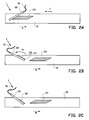
- the conveyor 31 is moved back step by step in the direction R as shown in figures 2A and 2C .
- Figure 2A shows how in the manner described above the first breaker ply 33 is first to be formed on the support surface of the conveyor 31.
- the supply device 35 is placed in the first position in which the supply device 35 is set for supplying the continuous rubber band 51 at a supply direction D which with the conveyance direction T includes a first angle that equals the first cord angle H1.
- the first breaker ply 33 is composed of strips from the rubber band 51 that are cut off at said first cord angle H1.
- the supply device 35 is moved, particularly swung over a swivel angle W, to the second position in which the supply device 35 is set for supplying the continuous rubber band 51 at a supply direction D which with the conveyance direction T includes a second angle that equals the second cord angle H2.
- the second breaker ply 32 can be formed in the above-mentioned manner using strips from the rubber band 51 that are cut off at a second cord angle H2.
- the second cord angle is not equal to the first cord angle H1, particularly substantially equal to 180 degrees minus the first cord angle H1.
- Manufacturing the second breaker ply 32 is shown in figures 2C , 2D and 2E .
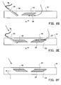
- a rubber strip arranging device 36 that can be moved over the conveyor 31 ensures the placing of one or more rubber strips 37 on the first breaker ply 33 on the conveyor 31, as shown in figure 2D .
- the strips 37 preferably project a little beyond the first breaker ply 33, whereas on the side of the first breaker ply 33 facing away from the building drum they indeed have to stop slightly before the end of the first breaker ply 33, as shown in figure 2F .
- One or more rubber strip arranging devices 36 that can be moved laterally, can arrange both strips 37, as shown in figures 2D and 2E .
- both breaker plies 32, 33 are conveyed in the conveyance direction T to the building drum 12 and wound thereon, as shown in figure 1 .
- the second breaker ply 32 is placed downstream of the first breaker ply 33, the second breaker ply 32 is first to be placed on the surface of the building drum 12 and after that the first breaker ply 33 is placed on the second breaker ply 32, wherein a breaker ply package is formed wherein the rubber strips are placed between the first and the second breaker ply.
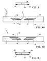
- the second breaker ply 32 is also provided with rubber strips 38, as shown in figure 4A .
- both breaker plies 32, 33 are ready, as shown in figure 4B , they are conveyed in conveyance direction T to the building drum 12 and wound thereon, as shown in figure 1 .
- Second breaker ply 32 that was produced second including rubber strips 38 is the first to be wound on the surface of the building drum 12, and subsequently the first breaker ply 33 that was produced first including the rubber strips 37 arranged thereon.
- a breaker ply package is formed having the rubber strips 37 between the breaker plies 32, 33 and the rubber strips 38 between the breaker ply 32 and the circumferential surface of the building drum 12.
- a triangular part 57 In order to correct the line of cut and obtain the wanted second cord angle H2, first a triangular part 57, as shown in figure 2B , needs to be cut off from of the leading part 56 of the rubber band 51 to be cut off, before cutting off second strips 55 for the second breaker ply 32 can be started with.
- the first cord angle H1 of the first breaker ply 33 and the second cord angle H2 of the second breaker ply 32 are exactly opposite in most green tyres.
- the second cord angle H2 therefore substantially equals 180 degrees minus the first cord angle H1.
- the second cord angle H2 can therefore be obtained by turning over or mirroring the first angle cord angle H1.
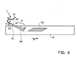
- the additional step regards the turning over, tilting, inverting or rotating of the leading part 56 of the rubber band 51 to be cut off over an angle of 180 degrees in the turning direction K about a longitudinal centre line of the rubber band 51.
- the supply device 35 on the side where the rubber band 51 is entered is provided with an entry section 61, able to turn over the rubber band 51 in manner to be further described and subsequently passing it through to an exit section 62 that conveys the rubber band 51 in a position over the support surface of the conveyor 31 for at the location of the leading part 56 of the rubber band 51 to be cut off, be cut off into strips.
- the additional step can be carried out prior to manufacturing the second breaker ply 32, preferably after the step and as shown in figure 2A , simultaneously with or prior to the step as shown in figure 2C .
- the necessity of cutting off a triangular part 57 at the leading part 56 of the rubber band 51 to be cut off can be removed and the quantity of material lost during manufacturing the breaker ply-tread package can be considerably reduced.
- the same supply device 35 and the same rubber band 51 can be used, so that switching again and again between various supply devices and different sources of rubber bands is not necessary. In that way the time required for manufacturing a green tyre can be reduced.
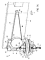
- FIGS 7A-D an exemplary embodiment of the supply device 35, particularly its entry section 61, is shown in more detail.
- the supply device 35 is provided with an elongated supporting body 40.
- the supporting body 40 is connected to a frame that is not shown via a swivel axle Z for with respect to the frame swinging the supply device 35 in a swinging rotary motion over swivel angle W about the swivel centre line Z.
- the entry section 61 and the exit section 62 are consecutively disposed in the supply direction D on the supporting body 40.
- the entry section 61 ensures the entry of the rubber band 51 in the supply device 35 according to a path that is indicated by the arrows A, B and C.
- the exit section 62 is provided with a conveyor belt assembly that is not shown and with which the rubber band 51 entered by the entry section 61 is passed onwards in the supply direction D to over the support surface of the conveyor. In the manner described above, the rubber band 51 is subsequently cut off at the wanted strip length into strips for manufacturing the breaker plies 32, 33 shown in figures 2A-F .
- the entry section 61 in this example comprises a turning section 7 for in a vertical entry direction A entering the rubber band 51.
- the turning section 7 is adapted for during the step according to figure 6 turning over the leading part 56 of the rubber band 51 to be cut off.
- the entry section 61 is furthermore provided with a passage section having a first passage conveyor belt assembly 8 and a second passage conveyor belt assembly 9 which jointly engage the leading part 56 of the rubber band 51 to be cut off as entered by the turning section 7, clamp it and pass it onwards to the cutting device via the passage path indicated by the arrows B and C.
- the turning section 7 comprises an annular bearing 76 having an outer ring 70 that is fixedly connected to a flange 42 of the supporting body 40 and an inner ring 71 that is rotatable within the outer ring 70 about a centre line of overturning S.
- the turning section 7 is provided with engagement members that are fixedly connected to the inner ring 71 and serve to engage the rubber band 51.
- the engagement members are first entry conveyor belt assembly 72 and a second entry conveyor belt assembly 73, the conveyor belts 77, 78 of which have been disposed in the centre of the inner ring 71 in mutual abutting contact or at a short distance from each other, so that at its entry in the vertical entry direction A the rubber band 51 is engaged between the conveyor belts of the entry conveyor belt assemblies 72, 73.
- the entry conveyor belt assemblies 72, 73 are elongated and extend on both sides of the annular bearing 76 for at the bottom side engaging the rubber band 51 in a clamping manner, passing the rubber band 51 onwards through the centre of the inner ring 71 and exiting the rubber band 51 on the other side of the annular bearing 76.
- the turning section 7 is provided with an entry drive that is not shown and that is adapted for driving the first and/or second entry conveyor belt assembly 72, 73 in two directions.
- the turning section 7 is furthermore provided with a turning drive 74 which via a transmission, in this example a drive belt 75, is connected to the inner ring 71 of the annular bearing 76.
- the turning drive 74 is adapted for rotating the inner ring 71 in two directions about the centre line of overturning S, and thus the entry conveyor belt assemblies 72, 73 disposed in the inner ring 71.
- the passage conveyor belt assemblies 8, 9 are disposed in the extension of the elongated entry conveyor belt assemblies 72, 73.
- the first passage conveyor belt assembly 8 comprises a large wheel 81 and a number of smaller wheels 82, 83 that jointly stretch a first passage conveyor belt 80.
- One of the wheels 81-83 is coupled to a passage drive that is not shown for driving the first passage conveyor belt assembly 8.
- the second passage conveyor belt assembly 9 comprises three wheels 91-93 that stretch a second passage conveyor belt 90.
- the second passage conveyor belt 90 is disposed in abutting contact with or at a short distance from the first passage conveyor belt 80 for in between them engaging, clamping and passing onwards the rubber band 51 that is supplied from the turning section 7.
- the second passage conveyor belt 90 is not driven but during passing through moves passively along with the movement of the rubber band 51.
- the second passage conveyor belt 90 presses the rubber band 51 against the first passage conveyor belt 80 so that at that location the rubber band 51 follows the contour of the large wheel 81. In that way the rubber band 51 entered in the vertical entry direction A is bent around via the path indicated by arrow B to the horizontal passage direction C indicated by arrow C.
- Figures 7A-D schematically show the operation of the entry section 61 of the supply device 35 for according to the step of figure 6 turning over the leading part 56 of the rubber band 51 to be cut off.
- FIG 7A the situation is shown in which the rubber band 51 in the vertical entry direction A has been entered in the supply device 35.
- the rubber band 51 is supplied from a supply roll or a strip production unit in a manner known per se via one or more loop-shaped paths that are not shown. Up until its entry in the supply device 35, the rubber band 51 is free to move or deform within its elastic range.
- the entry conveyor belt assemblies 72, 73 and the passage conveyor belt assemblies 8, 9 are driven such that via the path indicated by the arrows A, B, C and D the rubber band 51 is supplied to in the exit section 62 of the supply device 35.
- a cutting device that is not shown moves for cutting off a first strip 52 at the wanted strip length from the leading part 56 of the rubber band 51 to be cut off.
- the supply device 35 is in the first position, as a result of which the first strips 52 that are cut off from the rubber band 51, are cut off at an angle corresponding with the first cord angle H1.
- the resulting first strips 52 can be used for manufacturing the first breaker ply 33 in the manner described above.
- the first strip 52 shown in figure 7A is the last first strip 52 which has been cut off from the rubber band 51 at the first cord angle H1 for manufacturing the first breaker ply 33.
- the line of cut 53 at the outer end of the leading part 56 of the rubber band 51 to be cut off is the first cord angle H1.
- FIG 7B the situation is shown in which the entry conveyor belt assemblies 72, 73 and the passage conveyor belt assemblies 8, 9 have been driven opposite with respect to the situation shown in figure 7A .
- the rubber band 51 has been passed back from the exit section 62 into the entry section 61 along the pass-back path that is indicated by the arrows E, F and G. Passing back the rubber band 51 is stopped in the situation shown, in which the leading part 56 of the rubber band 51 to be cut off has arrived beyond engagement of the entry conveyor belt assemblies 8, 9 and only at the level of the pass-back limit L has been clamped between the entry conveyor belt assemblies 72, 73 of the turning section.
- FIG 7C the situation is shown in which the inner ring 71 and the entry conveyor belt assemblies 72, 73 of the turning section 7 disposed therein have been driven by the turning drive 74 in an approximately 180-degree rotation about the centre line of overturning S with respect to the outer ring 70 of the bearing 76.
- the 180-degree rotation of the entry conveyor belt assemblies 72, 73 is applied to the leading part 56 of the rubber band 51 to be cut off that is clamped by the turning section 7, which part as a result at the location of the clamping is turned 180 degrees about the longitudinal centre line of the rubber band 51 with respect to the situation as shown in figure 7B .
- the angle of the line of cut 53 of the leading part 56 of the rubber band 51 to be cut off, in the situation according to figure 7C is mirrored to the angle of the line of cut 53 in the situation according to figure 7B and thus is at the wanted second cord angle H2.
- a twist 54 has arisen to compensate for the turning over of the leading part 56 of the rubber band 51 to be cut off.
- Said twist 54 is shown in a strongly exaggerated manner and will in reality take place over a larger length and therefore gradually.
- the twist 54 will in most cases be smaller than 180 degrees as the supply device 35 itself swings over a swivel angle W that is opposite the turning direction K.
- FIG 7D the situation is shown in which the entry conveyor belt assemblies 72, 73 and the passage conveyor belt assemblies 8, 9 have been driven such that the rubber band 51 is supplied by the supply device 35 via the path indicated by the arrows B, C and D.
- This situation can be compared with the situation as shown in figure 7A .
- the leading part 56 of the rubber band 51 to be cut off and the rest of the rubber band 51 that have passed through the turning section 7, are now guided through the supply device 35 in an orientation that is opposite the original orientation of the rubber band 51 as shown in figure 7A .
- the twist 54 in the rubber band 51 takes place prior to the rubber band 51 entering the entry section 61 of the supply device 35. In that way the entire length of the entered part of the rubber band 51 within the supply device 35 is turned over.
- at least the leading part 56 of the rubber band 51 to be cut off has each time been turned over.
- the actions shown in figures 7B-D can be carried out after the step of manufacturing the first breaker ply 33 according to figure 2A , during the step of swinging according to figure 2B or prior to the step of manufacturing the second breaker ply 32 according to figure 2C .
- the actions according to figures 7B-D are carried out during the step of swinging according to figure 2B , so that the turned leading part 56 of the rubber band 51 to be cut off immediately or shortly after swinging is ready for manufacturing strips for the second breaker ply 32.
- the inner ring 71 of the bearing 76 can be rotated opposite with respect to the turning direction K, as shown in figure 7C , prior to manufacturing a new first breaker ply 33. In that case there is only question of a reciprocating turning motion of the inner ring 71 with respect to the outer ring 70 of the bearing 76 within the range of 180 degrees about the centre line of overturning S.
- the turning section 7 shown in 9A-D is an example of a part of the supply device 35 that is able to carry out the turning over of the leading part 56 of the rubber band 51 to be cut off according to the step of figure 6 . If loss of material is taken for granted and the steps according to figures 2A-F are carried out without the additional turning step according to figure 6 , the turning section 7 can be left out and a simplified entry section 61 will suffice. The simplified entry section 61 then will not comprise turning section 7, so that the rubber band 51 enters the entry section 61 without the possibility to be turned over.
- the invention relates to a method and a device for manufacturing a breaker ply package for a green tyre, wherein a rubber band is supplied by a supply device that can be moved between a first position and a second position, wherein the supply device can be moved between a first position in which the supply device is set for supplying the continuous rubber band at a supply direction which with the conveyance direction includes a first angle that equals the first cord angle, and a second position in which the supply device is set for supplying the continuous rubber band at a supply direction which with the conveyance direction includes a second angle that equals the second cord angle, wherein the second angle is not equal to the first angle.
Applications Claiming Priority (3)
| Application Number | Priority Date | Filing Date | Title |
|---|---|---|---|
| US201161504782P | 2011-07-06 | 2011-07-06 | |
| NL2007058A NL2007058C2 (nl) | 2011-07-06 | 2011-07-06 | Samenstel en werkwijze voor het vervaardigen van een groene band. |
| PCT/NL2012/050387 WO2013006039A1 (en) | 2011-07-06 | 2012-06-01 | Method and device for manufacturing a green tyre |
Publications (2)
| Publication Number | Publication Date |
|---|---|
| EP2598322A1 EP2598322A1 (en) | 2013-06-05 |
| EP2598322B1 true EP2598322B1 (en) | 2015-03-04 |
Family
ID=47437250
Family Applications (2)
| Application Number | Title | Priority Date | Filing Date |
|---|---|---|---|
| EP12730669.4A Not-in-force EP2598322B1 (en) | 2011-07-06 | 2012-06-01 | Method and device for manufacturing green tyres |
| EP12738643.1A Withdrawn EP2729299A1 (en) | 2011-07-06 | 2012-06-28 | Apparatus and method for manufacturing a green tyre |
Family Applications After (1)
| Application Number | Title | Priority Date | Filing Date |
|---|---|---|---|
| EP12738643.1A Withdrawn EP2729299A1 (en) | 2011-07-06 | 2012-06-28 | Apparatus and method for manufacturing a green tyre |
Country Status (10)
| Country | Link |
|---|---|
| US (2) | US9199423B2 (nl) |
| EP (2) | EP2598322B1 (nl) |
| JP (2) | JP6085599B2 (nl) |
| KR (2) | KR20140038336A (nl) |
| CN (2) | CN103097119B (nl) |
| BR (2) | BR112013004441A2 (nl) |
| NL (1) | NL2007058C2 (nl) |
| RU (2) | RU2560368C1 (nl) |
| TW (2) | TWI558542B (nl) |
| WO (2) | WO2013006039A1 (nl) |
Families Citing this family (10)
| Publication number | Priority date | Publication date | Assignee | Title |
|---|---|---|---|---|
| NL2015401B1 (en) * | 2015-09-04 | 2017-03-22 | Vmi Holland Bv | Assembly and method for tire building. |
| CN106217846B (zh) * | 2016-07-25 | 2018-12-21 | 浙江国自机器人技术有限公司 | 内胎自动拼接系统 |
| JP6993875B2 (ja) | 2017-12-28 | 2022-01-14 | Toyo Tire株式会社 | タイヤ構成部材の製造方法及びタイヤ構成部材の製造装置 |
| JP6970613B2 (ja) * | 2017-12-28 | 2021-11-24 | Toyo Tire株式会社 | タイヤ構成部材の製造方法及びタイヤ構成部材の製造装置 |
| JP6920193B2 (ja) * | 2017-12-28 | 2021-08-18 | Toyo Tire株式会社 | タイヤ用ベルトの製造方法及び製造装置 |
| JP6951969B2 (ja) * | 2017-12-28 | 2021-10-20 | Toyo Tire株式会社 | シート状ベルトの巻き取り方法及び巻き取り装置 |
| JP6993872B2 (ja) * | 2017-12-28 | 2022-01-14 | Toyo Tire株式会社 | タイヤ用ベルトの製造方法 |
| FR3084279B1 (fr) * | 2018-05-17 | 2020-07-10 | Compagnie Generale Des Etablissements Michelin | Installation de fabrication de nappes de renfort avec dispositif de retournement a plat de bandelettes |
| JP7215888B2 (ja) * | 2018-12-13 | 2023-01-31 | Toyo Tire株式会社 | 空気入りタイヤの製造方法 |
| JP7403304B2 (ja) * | 2019-12-13 | 2023-12-22 | Toyo Tire株式会社 | グリーンタイヤの成型装置及び成型方法 |
Family Cites Families (49)
| Publication number | Priority date | Publication date | Assignee | Title |
|---|---|---|---|---|
| GB372043A (en) * | 1930-07-11 | 1932-05-05 | Morgan & Wright | Improvements in methods and apparatus for manufacturing tires |
| FR2141480B1 (nl) * | 1971-06-03 | 1973-06-29 | Uniroyal | |
| US3757618A (en) * | 1971-10-01 | 1973-09-11 | Goodrich Co B F | Fabric cutting |
| US3894906A (en) | 1973-06-01 | 1975-07-15 | Nat Standard Co | Apparatus for making tire breakers |
| DE2740609C2 (de) * | 1977-09-09 | 1982-05-13 | Continental Gummi-Werke Ag, 3000 Hannover | Vorrichtung zum Aufbauen von Luftreifen oder deren Teilen |
| SU786172A1 (ru) * | 1979-03-22 | 1991-11-15 | Предприятие П/Я А-3404 | Лини дл сборки покрышек пневматических шин радиальной конструкции |
| CA1251717A (en) * | 1982-12-16 | 1989-03-28 | David J.B. Perkins | Method of manufacture of an elastomeric layer for incorporation into a pneumatic tyre and apparatus therefore |
| JPS59216704A (ja) * | 1983-05-24 | 1984-12-06 | Yokohama Rubber Co Ltd:The | 空気入りラジアルタイヤ |
| IT1203558B (it) * | 1986-05-20 | 1989-02-15 | Firestone Int Dev Spa | Metodo per la realizzazione di un pneumatico radiale di prima fase per veicoli |
| DE3712263A1 (de) | 1987-04-10 | 1988-10-27 | Hans Precht | Verfahren zur herstellung von reifenausgangsmaterial sowie wickel- und schneidmaschine |
| JP3124560B2 (ja) * | 1990-12-28 | 2001-01-15 | 株式会社ブリヂストン | プライ部材の成型方法 |
| JPH05245864A (ja) * | 1992-03-06 | 1993-09-24 | Yokohama Rubber Co Ltd:The | ゴム用圧延装置におけるゴムシートの寸法安定方法及び装置 |
| US5605596A (en) * | 1995-02-06 | 1997-02-25 | The Goodyear Tire & Rubber Company | Dual gumstrip applicator for tire cord belts |
| JP3439878B2 (ja) * | 1995-04-28 | 2003-08-25 | 横浜ゴム株式会社 | 帯状シート材料の端尺処理方法及び装置 |
| JPH09193259A (ja) * | 1996-01-19 | 1997-07-29 | Sumitomo Rubber Ind Ltd | 帯状部材の貼付方法及び貼付装置 |
| NL1002306C2 (nl) | 1996-02-12 | 1997-08-13 | Vmi Epe Holland | Samenstel van inrichtingen voor het bouwen van een groene band voor voertuigen. |
| US6039826A (en) * | 1997-04-22 | 2000-03-21 | The Yokohama Rubber Co., Ltd. | Method of forming green tire with strip winding |
| JP3822945B2 (ja) * | 1997-04-22 | 2006-09-20 | 横浜ゴム株式会社 | グリーンタイヤの成形方法 |
| JP2001009929A (ja) * | 1999-06-28 | 2001-01-16 | Yokohama Rubber Co Ltd:The | ベルト部材の端尺除去方法及びその装置 |
| CN1314532C (zh) * | 1999-09-07 | 2007-05-09 | 不二精工株式会社 | 生产用于气胎的胎体帘布材料的方法和设备 |
| JP2002028888A (ja) * | 2000-07-14 | 2002-01-29 | Yokohama Rubber Co Ltd:The | ゴム状弾性シートの切断方法及び装置 |
| JP4795576B2 (ja) | 2000-08-21 | 2011-10-19 | 不二精工株式会社 | リボン巻付装置、グリーンタイヤの製造システム、リボン巻付方法、及びグリーンタイヤの製造方法 |
| JP4556328B2 (ja) | 2000-12-27 | 2010-10-06 | 横浜ゴム株式会社 | 帯状ゴム部材の搬送,転写方法及びその装置 |
| US20030051794A1 (en) * | 2001-01-12 | 2003-03-20 | Nobuyuki Suda | Tire construction member producing method and device therefor |
| JP4316372B2 (ja) * | 2001-06-19 | 2009-08-19 | 株式会社ブリヂストン | タイヤ構成部材の形成方法 |
| US6736932B2 (en) * | 2001-09-14 | 2004-05-18 | The Goodyear Tire & Rubber Company | Cutting segment for a false drum |
| US6866736B2 (en) | 2001-09-21 | 2005-03-15 | The Goodyear Tire & Rubber Company | Combined transfer of toe guards and inner liner from false drum to building drum |
| US6773530B2 (en) * | 2001-09-21 | 2004-08-10 | The Goodyear Tire & Rubber Company | Method for manufacturing tires on a flexible manufacturing system |
| AU2003260149A1 (en) * | 2002-04-09 | 2003-10-20 | Matador A.S. | Method and plant for the manufacture of green tyres |
| FR2839005A1 (fr) * | 2002-04-25 | 2003-10-31 | Michelin Soc Tech | Procede pour la manutention de produits en bande en vue de leur utilisation pour la fabrication d'une enveloppe de pneumatique |
| DE60312986T2 (de) | 2002-06-03 | 2007-12-13 | Société de Technologie Michelin | Vorrichtung zur herstellung einer verstärkungsstruktur für einen reifen mit einem wulstfahnendrehmechanismus |
| JPWO2004011236A1 (ja) * | 2002-07-25 | 2005-11-24 | 株式会社ブリヂストン | タイヤ構成部材の貼付装置 |
| KR100970694B1 (ko) * | 2002-11-05 | 2010-07-16 | 피렐리 타이어 소시에떼 퍼 아찌오니 | 차륜용 타이어 제조방법 및 제조장치 |
| NL1022246C2 (nl) * | 2002-12-23 | 2004-06-24 | Vmi Epe Holland | Inrichting en werkwijze voor het maken van een gordellaag. |
| JP2004268548A (ja) * | 2003-03-12 | 2004-09-30 | Yokohama Rubber Co Ltd:The | 円筒状ゴム部材の成形組立て方法及びその装置 |
| US7341640B2 (en) * | 2004-02-27 | 2008-03-11 | Toyo Tire & Rubber Co., Ltd. | Method of and apparatus for forming rubber strip materials for building tires and method of building tires |
| US20060070504A1 (en) * | 2004-10-01 | 2006-04-06 | Downing Daniel R | Apparatus for cutting elastomeric materials |
| US8496772B2 (en) * | 2004-11-02 | 2013-07-30 | Toyo Tire & Rubber Co., Ltd. | Tire building method and building facility |
| JP4255435B2 (ja) | 2004-11-11 | 2009-04-15 | 住友ゴム工業株式会社 | 空気入りタイヤの製造方法 |
| DE602004025632D1 (de) | 2004-12-16 | 2010-04-01 | Pirelli | Verfahren und anlage zur herstellung von reifen für fahrzeugräder |
| NL1027846C2 (nl) * | 2004-12-22 | 2006-06-23 | Vmi Epe Holland | Inrichting voor het opnemen, verplaatsen en plaatsen van strips of stroken flexibel materiaal. |
| US7455002B2 (en) * | 2004-12-23 | 2008-11-25 | The Goodyear Tire & Rubber Company | Method for cutting elastomeric materials and the article made by the method |
| DE112005003648T5 (de) * | 2005-07-28 | 2008-06-19 | Toyo Tire & Rubber Co., Ltd. | Verfahren und Vorrichtung zum Herstellen von Luftsperr-Innenschichtelementen, und Reifen mit einer Luftsperr-Innenschicht |
| US8382925B2 (en) * | 2006-02-15 | 2013-02-26 | Toyo Tire & Rubber Co., Ltd. | Method and apparatus of adhering belt edge tape |
| US8304056B2 (en) * | 2006-07-10 | 2012-11-06 | Toyo Tire & Rubber Co., Ltd. | Rubber strip material |
| DE102008016922A1 (de) | 2007-04-23 | 2008-11-06 | Harburg-Freudenberger Maschinenbau Gmbh | Verfahren und Vorrichtung zur Handhabung von streifenförmigen Werkstücken |
| WO2009131578A1 (en) * | 2008-04-23 | 2009-10-29 | Michelin Recherche Et Technique S.A. | Method and apparatus for forming a multi-layered tire component |
| TWI426993B (zh) * | 2008-04-25 | 2014-02-21 | Vmi Holland Bv | 使用一建造圓筒及一運送裝置製造一綠色輪胎之方法 |
| NL2003474C2 (nl) * | 2009-09-11 | 2011-03-14 | Vmi Holland Bv | Inrichting en werkwijze voor het vervaardigen van een luchtveer. |
-
2011
- 2011-07-06 NL NL2007058A patent/NL2007058C2/nl not_active IP Right Cessation
-
2012
- 2012-06-01 US US13/814,360 patent/US9199423B2/en not_active Expired - Fee Related
- 2012-06-01 BR BR112013004441A patent/BR112013004441A2/pt not_active IP Right Cessation
- 2012-06-01 KR KR1020137005746A patent/KR20140038336A/ko active IP Right Grant
- 2012-06-01 WO PCT/NL2012/050387 patent/WO2013006039A1/en active Application Filing
- 2012-06-01 EP EP12730669.4A patent/EP2598322B1/en not_active Not-in-force
- 2012-06-01 JP JP2014518844A patent/JP6085599B2/ja not_active Expired - Fee Related
- 2012-06-01 CN CN201280002466.4A patent/CN103097119B/zh not_active Expired - Fee Related
- 2012-06-01 RU RU2013104087/05A patent/RU2560368C1/ru not_active IP Right Cessation
- 2012-06-04 TW TW101120094A patent/TWI558542B/zh not_active IP Right Cessation
- 2012-06-28 BR BR112014000187A patent/BR112014000187A2/pt not_active IP Right Cessation
- 2012-06-28 JP JP2014518846A patent/JP2014522757A/ja active Pending
- 2012-06-28 EP EP12738643.1A patent/EP2729299A1/en not_active Withdrawn
- 2012-06-28 RU RU2014104026/05A patent/RU2014104026A/ru not_active Application Discontinuation
- 2012-06-28 WO PCT/NL2012/050456 patent/WO2013006043A1/en active Application Filing
- 2012-06-28 CN CN201280033356.4A patent/CN103764380A/zh active Pending
- 2012-06-28 KR KR1020147000974A patent/KR20140051898A/ko not_active Application Discontinuation
- 2012-06-28 US US14/127,471 patent/US20140196834A1/en not_active Abandoned
- 2012-07-04 TW TW101124012A patent/TW201328858A/zh unknown
Also Published As
| Publication number | Publication date |
|---|---|
| US20130205590A1 (en) | 2013-08-15 |
| RU2560368C1 (ru) | 2015-08-20 |
| JP2014525849A (ja) | 2014-10-02 |
| TW201311434A (zh) | 2013-03-16 |
| US20140196834A1 (en) | 2014-07-17 |
| CN103097119B (zh) | 2015-01-07 |
| KR20140038336A (ko) | 2014-03-28 |
| BR112013004441A2 (pt) | 2016-05-31 |
| EP2729299A1 (en) | 2014-05-14 |
| TW201328858A (zh) | 2013-07-16 |
| RU2014104026A (ru) | 2015-08-20 |
| WO2013006039A1 (en) | 2013-01-10 |
| JP6085599B2 (ja) | 2017-02-22 |
| NL2007058C2 (nl) | 2013-01-08 |
| EP2598322A1 (en) | 2013-06-05 |
| CN103764380A (zh) | 2014-04-30 |
| US9199423B2 (en) | 2015-12-01 |
| BR112014000187A2 (pt) | 2017-06-27 |
| RU2013104087A (ru) | 2015-08-20 |
| JP2014522757A (ja) | 2014-09-08 |
| TWI558542B (zh) | 2016-11-21 |
| WO2013006043A1 (en) | 2013-01-10 |
| CN103097119A (zh) | 2013-05-08 |
| KR20140051898A (ko) | 2014-05-02 |
Similar Documents
| Publication | Publication Date | Title |
|---|---|---|
| EP2598322B1 (en) | Method and device for manufacturing green tyres | |
| JP4259704B2 (ja) | タイヤ成形システム及び成形方法 | |
| EP2978596B1 (en) | Process and apparatus for manufacturing tyres for vehicle wheels | |
| CN102458814A (zh) | 轮胎制造装置及轮胎制造方法 | |
| EP2978595B1 (en) | Process and apparatus for obtaining tyres for vehicle wheels | |
| US20160121568A1 (en) | Carcass band forming device and carcass band forming method | |
| RU2302341C2 (ru) | Способ и установка для изготовления невулканизированных шин | |
| EP2217432B1 (en) | Assembly of units for building an unvulcanised or green tyre for vehicles | |
| US20090090457A1 (en) | Tire cord application station and method | |
| US10759131B2 (en) | Method of building tire and tire building machine | |
| US20070125482A1 (en) | Bi-directional tooling head and method for tire cord application | |
| EP3089931B1 (en) | Method for guiding an elongated element for a process for obtaining vehicle wheel tyres and apparatus for obtaining vehicle tyres | |
| US8512495B2 (en) | Process and appartus for manufacturing tyres for vehicle wheels | |
| JP4901441B2 (ja) | タイヤコード取付けヘッド用のコードの緊張および搬送機構ならびにコード取付け方法 | |
| JP4167838B2 (ja) | タイヤ生産システム | |
| EP3148907B1 (en) | Apparatus for laying pairs of elongated elements on a forming drum and process for obtaining tyres for vehicle wheels | |
| JP2001232695A (ja) | 未加硫タイヤのベルトの成型方法 | |
| CN105269847B (zh) | 胎体帘布层的制造方法及充气轮胎的制造方法 | |
| US20080314524A1 (en) | Method for single line tire ply construction | |
| US20090090456A1 (en) | Synchronous drive and method for tire cord application | |
| US20240092045A1 (en) | Green tire manufacturing method and green tire manufacturing apparatus |
Legal Events
| Date | Code | Title | Description |
|---|---|---|---|
| PUAI | Public reference made under article 153(3) epc to a published international application that has entered the european phase |
Free format text: ORIGINAL CODE: 0009012 |
|
| 17P | Request for examination filed |
Effective date: 20130124 |
|
| AK | Designated contracting states |
Kind code of ref document: A1 Designated state(s): AL AT BE BG CH CY CZ DE DK EE ES FI FR GB GR HR HU IE IS IT LI LT LU LV MC MK MT NL NO PL PT RO RS SE SI SK SM TR |
|
| GRAP | Despatch of communication of intention to grant a patent |
Free format text: ORIGINAL CODE: EPIDOSNIGR1 |
|
| DAX | Request for extension of the european patent (deleted) | ||
| INTG | Intention to grant announced |
Effective date: 20141009 |
|
| GRAS | Grant fee paid |
Free format text: ORIGINAL CODE: EPIDOSNIGR3 |
|
| GRAA | (expected) grant |
Free format text: ORIGINAL CODE: 0009210 |
|
| AK | Designated contracting states |
Kind code of ref document: B1 Designated state(s): AL AT BE BG CH CY CZ DE DK EE ES FI FR GB GR HR HU IE IS IT LI LT LU LV MC MK MT NL NO PL PT RO RS SE SI SK SM TR |
|
| REG | Reference to a national code |
Ref country code: GB Ref legal event code: FG4D |
|
| REG | Reference to a national code |
Ref country code: CH Ref legal event code: EP |
|
| REG | Reference to a national code |
Ref country code: IE Ref legal event code: FG4D |
|
| REG | Reference to a national code |
Ref country code: AT Ref legal event code: REF Ref document number: 713458 Country of ref document: AT Kind code of ref document: T Effective date: 20150415 |
|
| REG | Reference to a national code |
Ref country code: DE Ref legal event code: R096 Ref document number: 602012005681 Country of ref document: DE Effective date: 20150416 |
|
| REG | Reference to a national code |
Ref country code: NL Ref legal event code: T3 |
|
| REG | Reference to a national code |
Ref country code: AT Ref legal event code: MK05 Ref document number: 713458 Country of ref document: AT Kind code of ref document: T Effective date: 20150304 |
|
| PG25 | Lapsed in a contracting state [announced via postgrant information from national office to epo] |
Ref country code: HR Free format text: LAPSE BECAUSE OF FAILURE TO SUBMIT A TRANSLATION OF THE DESCRIPTION OR TO PAY THE FEE WITHIN THE PRESCRIBED TIME-LIMIT Effective date: 20150304 Ref country code: FI Free format text: LAPSE BECAUSE OF FAILURE TO SUBMIT A TRANSLATION OF THE DESCRIPTION OR TO PAY THE FEE WITHIN THE PRESCRIBED TIME-LIMIT Effective date: 20150304 Ref country code: ES Free format text: LAPSE BECAUSE OF FAILURE TO SUBMIT A TRANSLATION OF THE DESCRIPTION OR TO PAY THE FEE WITHIN THE PRESCRIBED TIME-LIMIT Effective date: 20150304 Ref country code: NO Free format text: LAPSE BECAUSE OF FAILURE TO SUBMIT A TRANSLATION OF THE DESCRIPTION OR TO PAY THE FEE WITHIN THE PRESCRIBED TIME-LIMIT Effective date: 20150604 Ref country code: SE Free format text: LAPSE BECAUSE OF FAILURE TO SUBMIT A TRANSLATION OF THE DESCRIPTION OR TO PAY THE FEE WITHIN THE PRESCRIBED TIME-LIMIT Effective date: 20150304 Ref country code: LT Free format text: LAPSE BECAUSE OF FAILURE TO SUBMIT A TRANSLATION OF THE DESCRIPTION OR TO PAY THE FEE WITHIN THE PRESCRIBED TIME-LIMIT Effective date: 20150304 |
|
| REG | Reference to a national code |
Ref country code: SK Ref legal event code: T3 Ref document number: E 18558 Country of ref document: SK |
|
| REG | Reference to a national code |
Ref country code: LT Ref legal event code: MG4D |
|
| PG25 | Lapsed in a contracting state [announced via postgrant information from national office to epo] |
Ref country code: LV Free format text: LAPSE BECAUSE OF FAILURE TO SUBMIT A TRANSLATION OF THE DESCRIPTION OR TO PAY THE FEE WITHIN THE PRESCRIBED TIME-LIMIT Effective date: 20150304 Ref country code: RS Free format text: LAPSE BECAUSE OF FAILURE TO SUBMIT A TRANSLATION OF THE DESCRIPTION OR TO PAY THE FEE WITHIN THE PRESCRIBED TIME-LIMIT Effective date: 20150304 Ref country code: GR Free format text: LAPSE BECAUSE OF FAILURE TO SUBMIT A TRANSLATION OF THE DESCRIPTION OR TO PAY THE FEE WITHIN THE PRESCRIBED TIME-LIMIT Effective date: 20150605 Ref country code: AT Free format text: LAPSE BECAUSE OF FAILURE TO SUBMIT A TRANSLATION OF THE DESCRIPTION OR TO PAY THE FEE WITHIN THE PRESCRIBED TIME-LIMIT Effective date: 20150304 |
|
| PG25 | Lapsed in a contracting state [announced via postgrant information from national office to epo] |
Ref country code: EE Free format text: LAPSE BECAUSE OF FAILURE TO SUBMIT A TRANSLATION OF THE DESCRIPTION OR TO PAY THE FEE WITHIN THE PRESCRIBED TIME-LIMIT Effective date: 20150304 Ref country code: CZ Free format text: LAPSE BECAUSE OF FAILURE TO SUBMIT A TRANSLATION OF THE DESCRIPTION OR TO PAY THE FEE WITHIN THE PRESCRIBED TIME-LIMIT Effective date: 20150304 Ref country code: RO Free format text: LAPSE BECAUSE OF FAILURE TO SUBMIT A TRANSLATION OF THE DESCRIPTION OR TO PAY THE FEE WITHIN THE PRESCRIBED TIME-LIMIT Effective date: 20150304 Ref country code: PT Free format text: LAPSE BECAUSE OF FAILURE TO SUBMIT A TRANSLATION OF THE DESCRIPTION OR TO PAY THE FEE WITHIN THE PRESCRIBED TIME-LIMIT Effective date: 20150706 |
|
| PG25 | Lapsed in a contracting state [announced via postgrant information from national office to epo] |
Ref country code: IS Free format text: LAPSE BECAUSE OF FAILURE TO SUBMIT A TRANSLATION OF THE DESCRIPTION OR TO PAY THE FEE WITHIN THE PRESCRIBED TIME-LIMIT Effective date: 20150704 Ref country code: PL Free format text: LAPSE BECAUSE OF FAILURE TO SUBMIT A TRANSLATION OF THE DESCRIPTION OR TO PAY THE FEE WITHIN THE PRESCRIBED TIME-LIMIT Effective date: 20150304 |
|
| REG | Reference to a national code |
Ref country code: DE Ref legal event code: R097 Ref document number: 602012005681 Country of ref document: DE |
|
| PLBE | No opposition filed within time limit |
Free format text: ORIGINAL CODE: 0009261 |
|
| STAA | Information on the status of an ep patent application or granted ep patent |
Free format text: STATUS: NO OPPOSITION FILED WITHIN TIME LIMIT |
|
| PG25 | Lapsed in a contracting state [announced via postgrant information from national office to epo] |
Ref country code: MC Free format text: LAPSE BECAUSE OF FAILURE TO SUBMIT A TRANSLATION OF THE DESCRIPTION OR TO PAY THE FEE WITHIN THE PRESCRIBED TIME-LIMIT Effective date: 20150304 Ref country code: DK Free format text: LAPSE BECAUSE OF FAILURE TO SUBMIT A TRANSLATION OF THE DESCRIPTION OR TO PAY THE FEE WITHIN THE PRESCRIBED TIME-LIMIT Effective date: 20150304 |
|
| REG | Reference to a national code |
Ref country code: CH Ref legal event code: PL |
|
| 26N | No opposition filed |
Effective date: 20151207 |
|
| PG25 | Lapsed in a contracting state [announced via postgrant information from national office to epo] |
Ref country code: SI Free format text: LAPSE BECAUSE OF FAILURE TO SUBMIT A TRANSLATION OF THE DESCRIPTION OR TO PAY THE FEE WITHIN THE PRESCRIBED TIME-LIMIT Effective date: 20150304 Ref country code: LU Free format text: LAPSE BECAUSE OF FAILURE TO SUBMIT A TRANSLATION OF THE DESCRIPTION OR TO PAY THE FEE WITHIN THE PRESCRIBED TIME-LIMIT Effective date: 20150601 |
|
| REG | Reference to a national code |
Ref country code: IE Ref legal event code: MM4A |
|
| PG25 | Lapsed in a contracting state [announced via postgrant information from national office to epo] |
Ref country code: LI Free format text: LAPSE BECAUSE OF NON-PAYMENT OF DUE FEES Effective date: 20150630 Ref country code: IE Free format text: LAPSE BECAUSE OF NON-PAYMENT OF DUE FEES Effective date: 20150601 Ref country code: CH Free format text: LAPSE BECAUSE OF NON-PAYMENT OF DUE FEES Effective date: 20150630 |
|
| REG | Reference to a national code |
Ref country code: FR Ref legal event code: PLFP Year of fee payment: 5 |
|
| PGFP | Annual fee paid to national office [announced via postgrant information from national office to epo] |
Ref country code: GB Payment date: 20160513 Year of fee payment: 5 Ref country code: DE Payment date: 20160513 Year of fee payment: 5 |
|
| PG25 | Lapsed in a contracting state [announced via postgrant information from national office to epo] |
Ref country code: BE Free format text: LAPSE BECAUSE OF FAILURE TO SUBMIT A TRANSLATION OF THE DESCRIPTION OR TO PAY THE FEE WITHIN THE PRESCRIBED TIME-LIMIT Effective date: 20150304 |
|
| PGFP | Annual fee paid to national office [announced via postgrant information from national office to epo] |
Ref country code: IT Payment date: 20160519 Year of fee payment: 5 Ref country code: NL Payment date: 20160602 Year of fee payment: 5 Ref country code: SK Payment date: 20160530 Year of fee payment: 5 Ref country code: FR Payment date: 20160613 Year of fee payment: 5 |
|
| PG25 | Lapsed in a contracting state [announced via postgrant information from national office to epo] |
Ref country code: MT Free format text: LAPSE BECAUSE OF FAILURE TO SUBMIT A TRANSLATION OF THE DESCRIPTION OR TO PAY THE FEE WITHIN THE PRESCRIBED TIME-LIMIT Effective date: 20150304 |
|
| PG25 | Lapsed in a contracting state [announced via postgrant information from national office to epo] |
Ref country code: HU Free format text: LAPSE BECAUSE OF FAILURE TO SUBMIT A TRANSLATION OF THE DESCRIPTION OR TO PAY THE FEE WITHIN THE PRESCRIBED TIME-LIMIT; INVALID AB INITIO Effective date: 20120601 Ref country code: BG Free format text: LAPSE BECAUSE OF FAILURE TO SUBMIT A TRANSLATION OF THE DESCRIPTION OR TO PAY THE FEE WITHIN THE PRESCRIBED TIME-LIMIT Effective date: 20150304 Ref country code: SM Free format text: LAPSE BECAUSE OF FAILURE TO SUBMIT A TRANSLATION OF THE DESCRIPTION OR TO PAY THE FEE WITHIN THE PRESCRIBED TIME-LIMIT Effective date: 20150304 |
|
| PG25 | Lapsed in a contracting state [announced via postgrant information from national office to epo] |
Ref country code: CY Free format text: LAPSE BECAUSE OF FAILURE TO SUBMIT A TRANSLATION OF THE DESCRIPTION OR TO PAY THE FEE WITHIN THE PRESCRIBED TIME-LIMIT Effective date: 20150304 |
|
| PG25 | Lapsed in a contracting state [announced via postgrant information from national office to epo] |
Ref country code: TR Free format text: LAPSE BECAUSE OF FAILURE TO SUBMIT A TRANSLATION OF THE DESCRIPTION OR TO PAY THE FEE WITHIN THE PRESCRIBED TIME-LIMIT Effective date: 20150304 |
|
| REG | Reference to a national code |
Ref country code: DE Ref legal event code: R119 Ref document number: 602012005681 Country of ref document: DE |
|
| REG | Reference to a national code |
Ref country code: NL Ref legal event code: MM Effective date: 20170701 |
|
| GBPC | Gb: european patent ceased through non-payment of renewal fee |
Effective date: 20170601 |
|
| REG | Reference to a national code |
Ref country code: SK Ref legal event code: MM4A Ref document number: E 18558 Country of ref document: SK Effective date: 20170601 |
|
| PG25 | Lapsed in a contracting state [announced via postgrant information from national office to epo] |
Ref country code: NL Free format text: LAPSE BECAUSE OF NON-PAYMENT OF DUE FEES Effective date: 20170701 |
|
| REG | Reference to a national code |
Ref country code: FR Ref legal event code: ST Effective date: 20180228 |
|
| PG25 | Lapsed in a contracting state [announced via postgrant information from national office to epo] |
Ref country code: DE Free format text: LAPSE BECAUSE OF NON-PAYMENT OF DUE FEES Effective date: 20180103 Ref country code: GB Free format text: LAPSE BECAUSE OF NON-PAYMENT OF DUE FEES Effective date: 20170601 |
|
| PG25 | Lapsed in a contracting state [announced via postgrant information from national office to epo] |
Ref country code: FR Free format text: LAPSE BECAUSE OF NON-PAYMENT OF DUE FEES Effective date: 20170630 Ref country code: IT Free format text: LAPSE BECAUSE OF NON-PAYMENT OF DUE FEES Effective date: 20170601 Ref country code: SK Free format text: LAPSE BECAUSE OF NON-PAYMENT OF DUE FEES Effective date: 20170601 |
|
| PG25 | Lapsed in a contracting state [announced via postgrant information from national office to epo] |
Ref country code: MK Free format text: LAPSE BECAUSE OF FAILURE TO SUBMIT A TRANSLATION OF THE DESCRIPTION OR TO PAY THE FEE WITHIN THE PRESCRIBED TIME-LIMIT Effective date: 20150304 |
|
| PG25 | Lapsed in a contracting state [announced via postgrant information from national office to epo] |
Ref country code: AL Free format text: LAPSE BECAUSE OF FAILURE TO SUBMIT A TRANSLATION OF THE DESCRIPTION OR TO PAY THE FEE WITHIN THE PRESCRIBED TIME-LIMIT Effective date: 20150304 |