EP2585693B2 - Dosier- und mischanordnung zur verwendung bei der abgasnachbehandlung - Google Patents
Dosier- und mischanordnung zur verwendung bei der abgasnachbehandlung Download PDFInfo
- Publication number
- EP2585693B2 EP2585693B2 EP11729001.5A EP11729001A EP2585693B2 EP 2585693 B2 EP2585693 B2 EP 2585693B2 EP 11729001 A EP11729001 A EP 11729001A EP 2585693 B2 EP2585693 B2 EP 2585693B2
- Authority
- EP
- European Patent Office
- Prior art keywords
- mixing tube
- exhaust
- mixing
- housing body
- main housing
- Prior art date
- Legal status (The legal status is an assumption and is not a legal conclusion. Google has not performed a legal analysis and makes no representation as to the accuracy of the status listed.)
- Active
Links
Images


Classifications
-
- F—MECHANICAL ENGINEERING; LIGHTING; HEATING; WEAPONS; BLASTING
- F01—MACHINES OR ENGINES IN GENERAL; ENGINE PLANTS IN GENERAL; STEAM ENGINES
- F01N—GAS-FLOW SILENCERS OR EXHAUST APPARATUS FOR MACHINES OR ENGINES IN GENERAL; GAS-FLOW SILENCERS OR EXHAUST APPARATUS FOR INTERNAL-COMBUSTION ENGINES
- F01N3/00—Exhaust or silencing apparatus having means for purifying, rendering innocuous, or otherwise treating exhaust
- F01N3/08—Exhaust or silencing apparatus having means for purifying, rendering innocuous, or otherwise treating exhaust for rendering innocuous
- F01N3/10—Exhaust or silencing apparatus having means for purifying, rendering innocuous, or otherwise treating exhaust for rendering innocuous by thermal or catalytic conversion of noxious components of exhaust
- F01N3/18—Exhaust or silencing apparatus having means for purifying, rendering innocuous, or otherwise treating exhaust for rendering innocuous by thermal or catalytic conversion of noxious components of exhaust characterised by methods of operation; Control
- F01N3/20—Exhaust or silencing apparatus having means for purifying, rendering innocuous, or otherwise treating exhaust for rendering innocuous by thermal or catalytic conversion of noxious components of exhaust characterised by methods of operation; Control specially adapted for catalytic conversion
- F01N3/206—Adding periodically or continuously substances to exhaust gases for promoting purification, e.g. catalytic material in liquid form, NOx reducing agents
- F01N3/2066—Selective catalytic reduction [SCR]
-
- B—PERFORMING OPERATIONS; TRANSPORTING
- B01—PHYSICAL OR CHEMICAL PROCESSES OR APPARATUS IN GENERAL
- B01F—MIXING, e.g. DISSOLVING, EMULSIFYING OR DISPERSING
- B01F23/00—Mixing according to the phases to be mixed, e.g. dispersing or emulsifying
- B01F23/20—Mixing gases with liquids
- B01F23/21—Mixing gases with liquids by introducing liquids into gaseous media
- B01F23/213—Mixing gases with liquids by introducing liquids into gaseous media by spraying or atomising of the liquids
- B01F23/2132—Mixing gases with liquids by introducing liquids into gaseous media by spraying or atomising of the liquids using nozzles
-
- B—PERFORMING OPERATIONS; TRANSPORTING
- B01—PHYSICAL OR CHEMICAL PROCESSES OR APPARATUS IN GENERAL
- B01F—MIXING, e.g. DISSOLVING, EMULSIFYING OR DISPERSING
- B01F25/00—Flow mixers; Mixers for falling materials, e.g. solid particles
- B01F25/10—Mixing by creating a vortex flow, e.g. by tangential introduction of flow components
- B01F25/102—Mixing by creating a vortex flow, e.g. by tangential introduction of flow components wherein the vortex is created by two or more jets introduced tangentially in separate mixing chambers or consecutively in the same mixing chamber
-
- F—MECHANICAL ENGINEERING; LIGHTING; HEATING; WEAPONS; BLASTING
- F01—MACHINES OR ENGINES IN GENERAL; ENGINE PLANTS IN GENERAL; STEAM ENGINES
- F01N—GAS-FLOW SILENCERS OR EXHAUST APPARATUS FOR MACHINES OR ENGINES IN GENERAL; GAS-FLOW SILENCERS OR EXHAUST APPARATUS FOR INTERNAL-COMBUSTION ENGINES
- F01N13/00—Exhaust or silencing apparatus characterised by constructional features
- F01N13/08—Other arrangements or adaptations of exhaust conduits
-
- F—MECHANICAL ENGINEERING; LIGHTING; HEATING; WEAPONS; BLASTING
- F01—MACHINES OR ENGINES IN GENERAL; ENGINE PLANTS IN GENERAL; STEAM ENGINES
- F01N—GAS-FLOW SILENCERS OR EXHAUST APPARATUS FOR MACHINES OR ENGINES IN GENERAL; GAS-FLOW SILENCERS OR EXHAUST APPARATUS FOR INTERNAL-COMBUSTION ENGINES
- F01N3/00—Exhaust or silencing apparatus having means for purifying, rendering innocuous, or otherwise treating exhaust
- F01N3/08—Exhaust or silencing apparatus having means for purifying, rendering innocuous, or otherwise treating exhaust for rendering innocuous
- F01N3/10—Exhaust or silencing apparatus having means for purifying, rendering innocuous, or otherwise treating exhaust for rendering innocuous by thermal or catalytic conversion of noxious components of exhaust
- F01N3/24—Exhaust or silencing apparatus having means for purifying, rendering innocuous, or otherwise treating exhaust for rendering innocuous by thermal or catalytic conversion of noxious components of exhaust characterised by constructional aspects of converting apparatus
- F01N3/36—Arrangements for supply of additional fuel
-
- B—PERFORMING OPERATIONS; TRANSPORTING
- B01—PHYSICAL OR CHEMICAL PROCESSES OR APPARATUS IN GENERAL
- B01F—MIXING, e.g. DISSOLVING, EMULSIFYING OR DISPERSING
- B01F25/00—Flow mixers; Mixers for falling materials, e.g. solid particles
- B01F2025/93—Arrangements, nature or configuration of flow guiding elements
- B01F2025/931—Flow guiding elements surrounding feed openings, e.g. jet nozzles
-
- F—MECHANICAL ENGINEERING; LIGHTING; HEATING; WEAPONS; BLASTING
- F01—MACHINES OR ENGINES IN GENERAL; ENGINE PLANTS IN GENERAL; STEAM ENGINES
- F01N—GAS-FLOW SILENCERS OR EXHAUST APPARATUS FOR MACHINES OR ENGINES IN GENERAL; GAS-FLOW SILENCERS OR EXHAUST APPARATUS FOR INTERNAL-COMBUSTION ENGINES
- F01N2470/00—Structure or shape of exhaust gas passages, pipes or tubes
- F01N2470/02—Tubes being perforated
-
- F—MECHANICAL ENGINEERING; LIGHTING; HEATING; WEAPONS; BLASTING
- F01—MACHINES OR ENGINES IN GENERAL; ENGINE PLANTS IN GENERAL; STEAM ENGINES
- F01N—GAS-FLOW SILENCERS OR EXHAUST APPARATUS FOR MACHINES OR ENGINES IN GENERAL; GAS-FLOW SILENCERS OR EXHAUST APPARATUS FOR INTERNAL-COMBUSTION ENGINES
- F01N2470/00—Structure or shape of exhaust gas passages, pipes or tubes
- F01N2470/18—Structure or shape of exhaust gas passages, pipes or tubes the axis of inlet or outlet tubes being other than the longitudinal axis of apparatus
-
- F—MECHANICAL ENGINEERING; LIGHTING; HEATING; WEAPONS; BLASTING
- F01—MACHINES OR ENGINES IN GENERAL; ENGINE PLANTS IN GENERAL; STEAM ENGINES
- F01N—GAS-FLOW SILENCERS OR EXHAUST APPARATUS FOR MACHINES OR ENGINES IN GENERAL; GAS-FLOW SILENCERS OR EXHAUST APPARATUS FOR INTERNAL-COMBUSTION ENGINES
- F01N2610/00—Adding substances to exhaust gases
- F01N2610/02—Adding substances to exhaust gases the substance being ammonia or urea
-
- F—MECHANICAL ENGINEERING; LIGHTING; HEATING; WEAPONS; BLASTING
- F01—MACHINES OR ENGINES IN GENERAL; ENGINE PLANTS IN GENERAL; STEAM ENGINES
- F01N—GAS-FLOW SILENCERS OR EXHAUST APPARATUS FOR MACHINES OR ENGINES IN GENERAL; GAS-FLOW SILENCERS OR EXHAUST APPARATUS FOR INTERNAL-COMBUSTION ENGINES
- F01N2610/00—Adding substances to exhaust gases
- F01N2610/14—Arrangements for the supply of substances, e.g. conduits
- F01N2610/1453—Sprayers or atomisers; Arrangement thereof in the exhaust apparatus
-
- Y—GENERAL TAGGING OF NEW TECHNOLOGICAL DEVELOPMENTS; GENERAL TAGGING OF CROSS-SECTIONAL TECHNOLOGIES SPANNING OVER SEVERAL SECTIONS OF THE IPC; TECHNICAL SUBJECTS COVERED BY FORMER USPC CROSS-REFERENCE ART COLLECTIONS [XRACs] AND DIGESTS
- Y02—TECHNOLOGIES OR APPLICATIONS FOR MITIGATION OR ADAPTATION AGAINST CLIMATE CHANGE
- Y02T—CLIMATE CHANGE MITIGATION TECHNOLOGIES RELATED TO TRANSPORTATION
- Y02T10/00—Road transport of goods or passengers
- Y02T10/10—Internal combustion engine [ICE] based vehicles
- Y02T10/12—Improving ICE efficiencies
Definitions
- the present invention relates to an exhaust aftertreatment device according to the preamble to appended claim 1 which is based on EP2128398A1 .
- Vehicles equipped with internal combustion engines typically include exhaust systems that have aftertreatment components such as selective catalytic reduction (SCR) catalyst devices, lean NOx catalyst devices, or lean NOx trap devices to reduce the amount of undesirable gases, such as nitrogen oxides (NOx) in the exhaust.
- SCR selective catalytic reduction
- a doser injects reactants, such as urea, ammonia, or hydrocarbons, into the exhaust gas.
- reactants such as urea, ammonia, or hydrocarbons
- the exhaust gas and reactants convert the undesirable gases, such as NOx, into more acceptable gases, such as nitrogen and oxygen.
- the efficiency of the aftertreatment system depends upon how evenly the reactants are mixed with the exhaust gases. Therefore, there is a need for a flow device that provides a uniform mixture of exhaust gases and reactants.
- SCR exhaust treatment devices focus on the reduction of nitrogen oxides.
- a reductant e.g., aqueous urea solution
- the reductant reacts with nitrogen oxides while passing through an SCR substrate to reduce the nitrogen oxides to nitrogen and water.
- aqueous urea is used as a reductant
- the aqueous urea is converted to ammonia which in turn reacts with the nitrogen oxides to covert the nitrogen oxides to nitrogen and water.
- Dosing, mixing and evaporation of aqueous urea solution can be challenging because the urea and by-products from the reaction of urea to ammonia can form deposits on the surfaces of the aftertreatment devices. Such deposits can accumulate over time and partially block or otherwise disturb effective exhaust flow through the aftertreatment device.
- the dosing and mixing unit includes a mixing tube having a generally constant diameter along the length of the mixing tube.
- the mixing tube includes a first portion having a plurality of apertures (e.g., perforations) and a second portion having a solid wall without any apertures.
- the mixing tube includes a first end portioned adjacent the first portion of the mixing tube and a second end positioned adjacent the second portion of the mixing tube. The first end of the mixing tube is closed to exhaust flow and a doser is mounted at the first end of the mixing tube.
- the second end of the mixing tube is open and functions as an outlet for the mixing tube.
- the dosing and mixing unit also includes a swirling structure for swirling exhaust generally circumferentially (i.e., tangentially) around an exterior of the first portion of the mixing tube.
- the swirling exhaust enters the first portion of the mixing tube through the apertures of the mixing tube.
- the exhaust entering the mixing tube through the apertures has a tangential flow component that causes the flow to swirl within the mixing tube about a central axis of the mixing tube.
- the swirling exhaust then flows from the first portion of the mixing tube to the second portion of the mixing tube and exits the mixing tube through the second end of the mixing tube.
- the doser injects reactant into the interior of the mixing tube and the swirling motion of the exhaust within the mixing tube assists in uniformly mixing the reactant into the exhaust while the exhaust is within the mixing tube.
- the dosing and mixing unit includes a mixing tube having a plurality of apertures.
- the dosing and mixing unit also includes a swirl housing partially surrounding the mixing tube.
- the dosing and mixing unit further includes an inlet pipe attached to a side of the swirl housing and extending out from the side of the swirl housing in an angled tangential direction in relation to a central axis of the mixing tube.
- the dosing and mixing unit also includes a swirl structure for causing exhaust flow to swirl along a flow path around the central axis of the mixing tube.
- the dosing and mixing unit includes a doser for dispensing a reactant into the interior of the mixing tube.
- the swirling structure can include different types of structures for causing the exhaust to swirl about the mixing tube.
- the swirling structure can include an outer housing that at least partially encloses the mixing tube and that directs exhaust flow in a swirling motion about the mixing tube.
- the swirling structure can include a baffle that directs exhaust flow in a swirling motion about the mixing tube.
- dosing and mixing units in accordance with the principles of the present disclosure can be used as part of an SCR exhaust treatment system for reducing nitrogen oxides to nitrogen and water.
- the dosing and mixing units can be used to dose and mix reductants such as aqueous urea or ammonia at locations upstream from SCR substrates.
- dosing and mixing units in accordance with the principles of the present disclosure can be used to mix other types of reactants such as hydrocarbons (e.g., fuels such as diesel fuel or syngas) upstream from other types of substrates such as lean NOx catalyst devices, lean NOx traps, catalytic converters such as diesel oxidation catalyst (DOC) substrates and diesel particulate filter (DPF) substrates.
- hydrocarbons e.g., fuels such as diesel fuel or syngas
- substrates such as lean NOx catalyst devices, lean NOx traps, catalytic converters such as diesel oxidation catalyst (DOC) substrates and diesel particulate filter (DPF) substrates.
- DOC diesel oxidation catalyst
- DPF diesel particulate filter
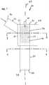
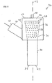
- FIGS 1-8 show a dosing and mixing unit 20 not forming part of the invention.
- the dosing and mixing unit 20 includes an inlet 22 and an outlet 24.
- the inlet 22 is formed by an inlet pipe 26 that extends to a swirl housing 28.
- the dosing and mixing unit 20 also includes a mixing tube 30 having a first end 32 positioned within the swirl housing 28 and a second end 34 that forms the outlet 24 of the dosing and mixing unit 20.
- the inlet pipe 26 is attached to a side 29 of the swirl housing 28 and extends out from the side 29 of the swirl housing 28 in an angled tangential direction in relation to a central axis 42 of the mixing tube 30.
- the inlet pipe 26 can be attached to a top portion of the side 27 of swirl housing 28 (see Figure 1 ) or a lower portion of the side 27 of swirl housing 28 (see Figure 6 .
- the inlet pipe 26 can also have different angles in relation to the central axis 42 such that the exhaust flow enters the swirl housing 28 in a direction towards a bottom of the swirl housing 28 (see Figures 1 and 6 ) or towards a top end 27 of swirl housing 28 (see Figure 7 ).
- the inlet pipe 26 is attached to the top end 27 of swirl housing 28 in an angled tangential direction in relation to a central axis 42 of the mixing tube 30.
- the angle between the inlet pipe 26 and the central axis 42 is in some embodiment an oblique angle.
- the mixing tube 30 has a first portion 36 positioned adjacent to the first end 32 of the mixing tube 30 and a second portion 38 positioned adjacent to the second end 34 of the mixing tube 30.
- the first portion 36 has a plurality of apertures 37 (e.g. perforations) and the second portion 38 has a solid wall without any apertures.
- the apertures 37 can be formed as circles, squares, slots or any other shape.
- the dosing and mixing unit 20 also includes a doser 40 mounted to the top end 27 of the swirl housing 28 adjacent to the first end 32 of the mixing tube 30.
- the doser 40 is adapted for dispensing reactant into an interior region of the mixing tube 30.
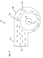
- exhaust enters the dosing and mixing unit 20 through the inlet 22 and is swirled circumferentially (i.e., tangentially) through a swirl structure about the exterior of the first portion 36 of the mixing tube 30 by the swirl housing 28.
- the exhaust flow swirls circumferentially around the first portion 36 of the mixing tube 30, the exhaust gas enters the interior of the mixing tube 30 through the apertures 37.
- the exhaust flow entering the interior of the mixing tube 30 through the apertures 37 has a tangential/circumferential flow component that causes the exhaust to swirl within the interior of the mixing tube 30.
- the doser 40 dispenses reactant into the swirling exhaust within the interior of the mixing tube where the swirling action of the exhaust assists in uniformly mixing the reactant within the exhaust. Swirling flow of the exhaust continues from the first portion 36 of the mixing tube 30 to the second portion 38 of the mixing tube 30 whereby mixing is enhanced as the exhaust moves through the length of the mixing tube 30. After the swirling exhaust has traveled through the mixing tube in a direction extending from the first end 32 to the second end 34 of the mixing tube 30, the exhaust exits the dosing and mixing unit 20 through the outlet 24. As is seen in figure 2 , the swirl structure has in some embodiments a cross-section that gradually decreases along the exhaust flow path.
- the mixing tube 30 of the dosing and mixing unit 20 defines the central axis 42 and has a length that extends along the central axis 42 from the first end 32 to the second end 34 of the mixing tube 30.
- the mixing tube 30 is cylindrical in shape and has in some embodiments (shown in Figures 1-7 ) a constant diameter along the entire length of the mixing tube 30.
- the first and second portions 36, 38 of the mixing tube 30 have constant diameters along their respective lengths.
- the first and second portions 36, 38 of the mixing tube 30 are shown having equal diameters.
- the first end 32 of the mixing tube 30 has a larger diameter than the second end 34.
- the first portion 36 of the mixing tube 30 has a diameter that gradually decreases along its length towards the second portion 38.
- the first end 32 of the mixing tube 30 is blocked by the top end 27 of swirl housing 28 so that exhaust flow can not pass through the first end 32 of the mixing tube 30.
- the first end 32 of the mixing tube 30 is arranged at a distance from the top end 27 of the swirl housing 28, forming a gap 52.
- the doser 40 is positioned at the first end 32 of the mixing tube 30 and is aligned along the central axis 42.
- the swirling motion of the exhaust can increase in intensity as the swirling exhaust moves axially through the first portion 36 of the mixing tube in a direction toward the second portion 38 of the mixing tube 38.
- the exhaust is swirling at an increased rate.
- the doser 40 can include an injector that injects reactant in a spray cone aligned along the central axis 42 of the mixing tube 30.
- the swirling action of the exhaust and the converging flow passing through the apertures 37 assists in narrowing the spray cone angle thereby inhibiting wetting of the interior of the mixing tube 30 and minimizing deposit formation within the mixing tube and downstream from the mixing tube.
- the swirling action is particularly suited for breaking-up, mixing and evaporating aqueous urea in a relatively short time frame/distance.
- the swirl housing 28 at least partially encloses the first portion 36 of the mixing tube 30 and has an arrangement that directs exhaust flow tangentially relative to the outer surface of the mixing tube 30 such that the exhaust swirls circumferentially around the exterior of the mixing tube 30.
- the exhaust flows in a single direction (e.g., clockwise relative to the central longitudinal axis as shown at Figure 2 ) around at least 75 percent of the outer diameter of the mixing tube 30.
- the exhaust flow direction turns at least 270 degrees around the outer diameter of the mixing tube 30.
- portions of the exhaust progressively enter the interior of the first portion 36 of the mixing tube 30 through the apertures 37.
- the swirl housing 28 has a curved/bent surface 44 that curves along and opposes the outer surface of the first portion 36 of the mixing tube 30.
- the surface 44 is arranged to transition progressively closer to the outer surface of the first portion 36 of the mixing tube 30 as the surface extends in the circumferential direction of exhaust flow.
- the mixing tube 30 is arranged such in the swirl housing 28 that the central axis 42 of the mixing tube 30 is not in parallel with a longitudinal axis of the swirl housing 28, i.e. the second portion 28 of the mixing tube 30 extends from the swirl housing 28 in an angled direction.
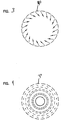
- Figures 9 and 10 show a dosing and mixing unit 20, which does not form part of the invention and which is configured in the same manner and includes the same features as described in conjunction with Figures 1-8 .
- the unit 20 further comprises indents 62 or some other kind of profile for causing the exhaust to swirl within the interior of the mixing tube 30.
- the swirl housing 28 includes indents or other kinds of profiles on the inside of the top end 27 for causing the swirl.
- the unit 20 includes a screw or helical shaped device arranged around the mixing tube 30 for causing the exhaust to swirl.
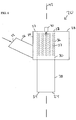
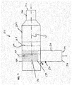
- FIGS 11 and 12 show an aftertreatment device 120 in accordance with an embodiment of the invention.
- the aftertreatment device 120 includes an inlet 122 and an outlet 124.
- the inlet 122 is formed by an inlet pipe 126 that extends to a substrate housing 128.
- a substrate 129 e.g., a DPF substrate or DOC substrate
- the aftertreatment device 120 also includes a mixing tube 130 having the same configuration as the mixing tube 30.
- the mixing tube 130 has a first end 132 positioned within the substrate housing 128 and a second end 134 that forms the outlet 124 of the aftertreatment device 120.
- the mixing tube 130 has a first portion 136 positioned adjacent to the first end 132 of the mixing tube 130 and a second portion 138 positioned adjacent to the second end 134 of the mixing tube 130.
- the first portion 136 has a plurality of apertures 137 (e.g., perforations) and the second portion 138 has a solid wall without any apertures.
- the apertures 137 can be formed as circles, squares, slots or any other shape.
- the aftertreatment device 120 also includes a doser 140 mounted to the housing 128 adjacent to the first end 132 of the mixing tube 130.
- the doser 140 is adapted for dispensing reactant into an interior region of the mixing tube 130.
- a deflector baffle 150 is positioned between the substrate 129 and the first portion 136 of the mixing tube 130.
- the deflector baffle 150 is configured to cause the exhaust to flow circumferentially in one direction around at least 270 degrees of the exterior of the outer diameter of the first portion 136 of the mixing tube 30.
- the baffle 150 directs the flow in a tangential direction relative to the outer diameter of the mixing tube 30.
- the mixing tube 130 can be bent so that an out put end of the tube angles away from the inlet 122.
- the tube 130 can be straight and the entire tube 130 can be angled at angle ⁇ relative to a central axis of the housing 128.
- the angle ⁇ is in the range of 60-90 degrees. In other embodiments, the angle ⁇ is less than 90 degrees, or less than 80 degrees, or in the range of 60-80 degrees. In other embodiments, the angle ⁇ is 90 degrees. The angle ⁇ is measured between the outer end of the tube 130 and the main body of the housing 128.
- the tube 130 can be offset from the center of the housing 128 so as to be closer to a first side 131 (e.g., a top side) of the housing as compared to a second side 133 (e.g., a bottom side) of the housing 128.
- a first side 131 e.g., a top side
- a second side 133 e.g., a bottom side
- exhaust enters the device 120 through the inlet 122 and passes through the substrate 129 where the exhaust is initially treated (e.g., contaminants removed by filtration or chemically through a catalyzed reaction at the substrate).
- the baffle 150 causes the exhaust to swirl circumferentially (i.e., tangentially) through a swirl structure about the exterior of the first portion 136 of the mixing tube 130.
- the exhaust flow swirls circumferentially around the first portion 136 of the mixing tube 130, the exhaust gas enters the interior of the mixing tube 130 through the apertures 137.
- the exhaust flow entering the interior of the mixing tube 130 through the apertures 137 has a tangential/circumferential flow component that causes the exhaust to swirl within the interior of the mixing tube 130.
- the doser 140 dispenses reactant into the swirling exhaust within the interior of the mixing tube where the swirling action of the exhaust assists in uniformly mixing the reactant within the exhaust.
- Swirling flow of the exhaust continues from the first portion 136 of the mixing tube 130 to the second portion 138 of the mixing tube 130 whereby mixing is enhanced as the exhaust moves through the length of the mixing tube 130.
- the swirl structure has a cross-section that gradually decreases along the exhaust flow path.
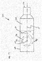
- FIG. 13 shows a doser and mixing unit 220 not forming part of the invention.
- the unit 220 includes an inlet 222 and an outlet 224.
- the inlet 222 is formed by an inlet pipe 226 that extends to a swirl housing 128.
- the unit 220 also includes a mixing tube 230 having the same configuration as the mixing tube 30 shown and described in conjunction with Figures 1-10 .
- the inlet pipe 226 is arranged with a radial offset from a central axis of the mixing tube 230 such that the incoming exhaust through the inlet 222 has a flow direction that is generally in parallel of the direction of the outgoing exhaust through outlet 224.
- the mixing tube 230 has a first end 232 positioned within the swirl housing 228 and a second end 234 that forms the outlet 224 of the unit 220.
- the mixing tube 230 has a first portion 236 positioned adjacent to the first end 232 of the mixing tube 230 and a second portion 238 positioned adjacent to the second end 234 of the mixing tube 230.
- the first portion 236 has a plurality of apertures 237 (e.g., perforations) and the second portion 238 has a solid wall without any apertures.
- the apertures 237 can be formed as circles, squares, slots or any other shape.
- the unit 220 also includes a doser 240 mounted to the housing 228 adjacent to the first end 232 of the mixing tube 230.
- the doser 240 is adapted for dispensing reactant into an interior region of the mixing tube 230.
- a deflector baffle 250 is positioned within the swirl housing 228 between the inlet pipe 226 and the first portion 236 of the mixing tube 230.
- the deflector baffle 250 is configured to cause the exhaust to flow circumferentially in one direction around at least 270 degrees of the exterior of the outer diameter of the first portion 236 of the mixing tube 230.
- the baffle 250 directs the flow in a tangential direction relative to the outer diameter of the mixing tube 230.
- the exhaust gas enters the interior of the mixing tube 230 through the apertures 237.
- the exhaust flow entering the interior of the mixing tube 230 through the apertures 237 has a tangential/circumferential flow component that causes the exhaust to swirl within the interior of the mixing tube 230.
- the doser 240 dispenses reactant into the swirling exhaust within the interior of the mixing tube where the swirling action of the exhaust assists in uniformly mixing the reactant within the exhaust. Swirling flow of the exhaust continues from the first portion 236 of the mixing tube 230 to the second portion 238 of the mixing tube 230 whereby mixing is enhanced as the exhaust moves through the length of the mixing tube 230. After the swirling exhaust has traveled through the mixing tube 230 in a direction extending from the first end 232 to the second end 234 of the mixing tube 230, the exhaust exits the unit 220 through the outlet 224.
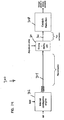
- Figure 14 shows a system 300, not forming part of the invention, including the dosing and mixing unit 20.
- the system includes an internal combustion engine 302.
- a pipe 304 carries exhaust from the engine 302 to the dosing and mixing unit 20 where reactant (e.g., aqueous urea) is injected into the exhaust stream and mixed with the exhaust stream.
- a pipe 306 carries the exhaust stream containing the reactant to an SCR device 308 where nitrogen oxides are reduced to nitrogen and water.
- Figure 15 shows a system 400 that is the same as the system 300 except a separate aftertreatment substrate (e.g., a DPF or DOC) is positioned between the engine 300 and the dosing and mixing unit 20.
- Figure 16 shows a system 500 that is the same as the system 300 except the aftertreatment device 120 has been substituted for the dosing and mixing unit 20.
- a separate aftertreatment substrate e.g., a DPF or DOC
- a selective catalytic reduction (SCR) catalyst device is typically used in an exhaust system to remove undesirable gases such as nitrogen oxides (NOx) from the vehicle's emissions.
- SCR's are capable of converting NOx to nitrogen and oxygen in an oxygen rich environment with the assistance of reactants such as urea or ammonia, which are injected into the exhaust stream upstream of the SCR through the doser 40.
- reactants such as urea or ammonia
- other aftertreatment devices such as lean NOx catalyst devices or lean NOx traps could be used in place of the SCR catalyst device, and other reactants (e.g., hydrocarbons) can be dispensed by the doser.
- a lean NOx catalyst device is also capable of converting NOx to nitrogen and oxygen.
- lean NOx catalysts use hydrocarbons as reducing agents/reactants for conversion of NOx to nitrogen and oxygen.
- the hydrocarbon is injected into the exhaust stream upstream of the lean NOx catalyst.
- the NOx reacts with the injected hydrocarbons with the assistance of a catalyst to reduce the NOx to nitrogen and oxygen.
- the exhaust treatment systems 400 and 500 will be described as including an SCR, it will be understood that the scope of the present disclosure is not limited to an SCR as there are various catalyst devices that can be used in accordance with the principles of the present disclosure.
- the lean NOx traps use a material such as barium oxide to absorb NOx during lean burn operating conditions.
- the NOx is desorbed and converted to nitrogen and oxygen by reaction with hydrocarbons in the presence of catalysts (precious metals) within the traps.
- Figures 17a-17f are top views of a dosing and mixing unit 20, not forming part of the invention, as described and shown in conjunction with Figures 1-10 and show different means for creating exhaust flow swirl.
- Figure 17a illustrates a swirl structure that has the same cross-section around the outer diameter of the mixing tube 30.
- the swirl housing 28 includes a stop wall 63 that forces the exhaust flow to enter the mixing tube 30.
- the dosing and mixing unit 20 includes one or more flow guide devices 64 arranged between an outer wall of the mixing tube 30 and an inner wall of the swirl housing 28. The flow guide devices 64 may extend from a bottom of the swirl housing 28 or from a top of the swirl housing 28.
- the flow guide device(s) 64 may also be arranged on the inner wall of the swirl housing 28 (as shown in Figure 17d ) or on the outer wall of the mixing tube 30 (not shown). Further, according to some embodiments, the mixing tube 30 may be provided with fins 65 inwardly extending from an inner wall of the mixing tube 30 (see Figure 17e). Figure 17f illustrates that swirl structure transits from a circular cross-section into an oval or elliptical cross-section along the flow path.
Landscapes
- Chemical & Material Sciences (AREA)
- Engineering & Computer Science (AREA)
- Chemical Kinetics & Catalysis (AREA)
- Combustion & Propulsion (AREA)
- Mechanical Engineering (AREA)
- General Engineering & Computer Science (AREA)
- Health & Medical Sciences (AREA)
- Toxicology (AREA)
- Exhaust Gas After Treatment (AREA)
Claims (2)
- Abgasnachbehandlungsvorrichtung, umfassend:einen Einlass (122) und einen Auslass (124);einen Hauptgehäusekörper (128) zwischen dem Einlass und dem Auslass, wobei der Hauptgehäusekörper (128) eine erste Mittelachse aufweist;ein Mischrohr (130), das einen ersten Abschnitt (136) innerhalb des Hauptgehäusekörpers (128), und der über die gesamte Höhe des Hauptgehäuses (128) verläuft, und einen zweiten Abschnitt (138) aufweist, der vom Hauptgehäusekörper nach außen vorsteht, wobei der erste Abschnitt mehrere Öffnungen (137) definiert, wobei der zweite Abschnitt den Auslass definiert, wobei das Mischrohr (130) eine zweite Mittelachse aufweist;eine Wirbelstruktur;einen Dosierer (140), der Reaktant in das Mischrohr (130) abgibt; undein Abgasnachbehandlungssubstrat (129), das innerhalb des Hauptgehäusekörpers (128) an einer Stelle zwischen dem Einlass (122) und dem ersten Abschnitt (136) des Mischrohrs (130) angeordnet ist;wobei die Wirbelstruktur zum Wirbeln von Abgas um den ersten Abschnitt (136) des Mischrohrs (130) konfiguriert ist,wobei die Wirbelstruktur ein Ablenkblech (150) enthält, das zwischen dem Substrat (129) und dem ersten Abschnitt (136) des Mischrohrs (130) angeordnet ist,dadurch gekennzeichnet, dass das Ablenkblech (150) zum Bewirken konfiguriert ist, dass das Abgas umfänglich in einer Richtung um zumindest 270 Grad der Außenseite des Außendurchmessers des ersten Abschnitts (136) des Mischrohrs (130) strömt;dass das Ablenkblech (150) vollständig über einen Durchmesser des Mischrohrs (130) verläuft und über die gesamte Höhe des Hauptgehäusekörpers (128) verläuft;dass das Ablenkblech (150) einen flachen Abschnitt und einen gebogenen Abschnitt aufweist, wobei der flache Abschnitt vom Hauptgehäusekörper (128) aus verläuft und der gebogene Abschnitt vom flachen Abschnitt aus verläuft, und wobei der gebogene Abschnitt in einer stromabwärtigen Richtung vom flachen Abschnitt weg gekehrt ist, wobei der gebogene Abschnitt in einem Abstand zum Hauptgehäusekörper (128) liegt, um einen Spalt zwischen dem gebogenen Abschnitt und dem Hauptgehäusekörper (128) zu lassen;und dass das Substrat (129) eine dritte Mittelachse (C) definiert, die mit der ersten Mittelachse zusammenfällt und das Mischrohr (130) innerhalb des Gehäuses (128) schneidet, wodurch die dritte Mittelachse (C) die zweite Mittelachse des Mischrohrs (130) schneidet.
- Abgasnachbehandlungsvorrichtung nach Anspruch 1, wobei Abgas durch den Einlass (122) in die Vorrichtung (120) eindringt und das Substrat (129) durchläuft, wo das Abgas anfangs behandelt wird, und dann durch den Auslass (124) nach außen tritt.
Priority Applications (1)
| Application Number | Priority Date | Filing Date | Title |
|---|---|---|---|
| EP17175426.0A EP3267005B2 (de) | 2010-06-22 | 2011-06-22 | Abgasnachbehandlungsvorrichtung |
Applications Claiming Priority (2)
| Application Number | Priority Date | Filing Date | Title |
|---|---|---|---|
| US35741810P | 2010-06-22 | 2010-06-22 | |
| PCT/US2011/041493 WO2011163395A1 (en) | 2010-06-22 | 2011-06-22 | Dosing and mixing arrangement for use in exhaust aftertreatment |
Related Child Applications (2)
| Application Number | Title | Priority Date | Filing Date |
|---|---|---|---|
| EP17175426.0A Division-Into EP3267005B2 (de) | 2010-06-22 | 2011-06-22 | Abgasnachbehandlungsvorrichtung |
| EP17175426.0A Division EP3267005B2 (de) | 2010-06-22 | 2011-06-22 | Abgasnachbehandlungsvorrichtung |
Publications (3)
| Publication Number | Publication Date |
|---|---|
| EP2585693A1 EP2585693A1 (de) | 2013-05-01 |
| EP2585693B1 EP2585693B1 (de) | 2017-06-14 |
| EP2585693B2 true EP2585693B2 (de) | 2020-08-12 |
Family
ID=44562684
Family Applications (2)
| Application Number | Title | Priority Date | Filing Date |
|---|---|---|---|
| EP17175426.0A Active EP3267005B2 (de) | 2010-06-22 | 2011-06-22 | Abgasnachbehandlungsvorrichtung |
| EP11729001.5A Active EP2585693B2 (de) | 2010-06-22 | 2011-06-22 | Dosier- und mischanordnung zur verwendung bei der abgasnachbehandlung |
Family Applications Before (1)
| Application Number | Title | Priority Date | Filing Date |
|---|---|---|---|
| EP17175426.0A Active EP3267005B2 (de) | 2010-06-22 | 2011-06-22 | Abgasnachbehandlungsvorrichtung |
Country Status (4)
| Country | Link |
|---|---|
| US (4) | US9670811B2 (de) |
| EP (2) | EP3267005B2 (de) |
| FI (1) | FI9882U1 (de) |
| WO (1) | WO2011163395A1 (de) |
Families Citing this family (116)
| Publication number | Priority date | Publication date | Assignee | Title |
|---|---|---|---|---|
| US8173088B2 (en) * | 2010-02-24 | 2012-05-08 | International Engine Intellectual Property Company, Llc | Method, system and apparatus for liquid injection into a gas system |
| DE202008001547U1 (de) | 2007-07-24 | 2008-04-10 | Emcon Technologies Germany (Augsburg) Gmbh | Baugruppe zur Einbringung eines Reduktionsmittels in die Abgasleitung einer Abgasanlage einer Verbrennungskraftmaschine |
| JP4884332B2 (ja) * | 2007-08-21 | 2012-02-29 | トヨタ自動車株式会社 | 内燃機関の排気システム |
| EP2358982B1 (de) | 2008-12-17 | 2017-11-08 | Donaldson Company, Inc. | Flussvorrichtung für ein abgassystem |
| EP2524123B1 (de) | 2010-01-12 | 2016-11-23 | Donaldson Company, Inc. | Strömungsvorrichtung für ein abgasbehandlungssystem |
| EP3267005B2 (de) | 2010-06-22 | 2023-12-27 | Donaldson Company, Inc. | Abgasnachbehandlungsvorrichtung |
| SE535198C2 (sv) * | 2010-09-30 | 2012-05-15 | Scania Cv Ab | Arrangemang för att införa ett vätskeformigt medium i avgaser från en förbränningsmotor |
| SE535219C2 (sv) * | 2010-10-06 | 2012-05-29 | Scania Cv Abp | Arrangemang för att införa ett vätskeformigt medium i avgaser från en förbränningsmotor |
| JP5349575B2 (ja) * | 2011-12-27 | 2013-11-20 | 株式会社小松製作所 | 還元剤水溶液ミキシング装置及び排気ガス後処理装置 |
| US8932530B2 (en) | 2011-12-27 | 2015-01-13 | Komatsu Ltd. | Reducing agent aqueous solution mixing device and exhaust gas post-treatment device |
| US8916100B2 (en) | 2011-12-27 | 2014-12-23 | Komatsu Ltd. | Reducing agent aqueous solution mixing device and exhaust gas post-treatment device |
| JP5985822B2 (ja) * | 2011-12-28 | 2016-09-06 | 日野自動車株式会社 | 排気浄化装置 |
| JP6053096B2 (ja) * | 2012-01-12 | 2016-12-27 | 日野自動車株式会社 | 排気浄化装置 |
| US8938954B2 (en) | 2012-04-19 | 2015-01-27 | Donaldson Company, Inc. | Integrated exhaust treatment device having compact configuration |
| DE102012014333A1 (de) * | 2012-07-20 | 2014-01-23 | Man Truck & Bus Ag | Mischvorrichtung zur Nachbehandlung von Abgasen |
| DE102012014334A1 (de) * | 2012-07-20 | 2014-05-15 | Man Truck & Bus Ag | Mischvorrichtung zur Nachbehandlung von Abgasen |
| JP6009260B2 (ja) * | 2012-07-25 | 2016-10-19 | 日野自動車株式会社 | 排気浄化装置 |
| AT15067U3 (de) | 2012-10-08 | 2017-10-15 | Avl List Gmbh | Abgasreinigungseinrichtung |
| DE102012021017B4 (de) * | 2012-10-26 | 2026-03-19 | Mercedes-Benz Group AG | Abgassystem |
| CN104066943B (zh) | 2013-01-17 | 2016-08-24 | 株式会社小松制作所 | 还原剂水溶液混合装置及具备它的废气后处理装置 |
| US8893481B2 (en) | 2013-01-17 | 2014-11-25 | Komatsu Ltd. | Reductant aqueous solution mixing device and exhaust aftertreatment device provided with the same |
| CN104066941B (zh) | 2013-01-17 | 2016-01-20 | 株式会社小松制作所 | 还原剂水溶液混合装置以及具备其的排气后处理装置 |
| WO2014112072A1 (ja) | 2013-01-17 | 2014-07-24 | 株式会社小松製作所 | 還元剤水溶液ミキシング装置およびこれを備えた排気ガス後処理装置 |
| US9707525B2 (en) | 2013-02-15 | 2017-07-18 | Donaldson Company, Inc. | Dosing and mixing arrangement for use in exhaust aftertreatment |
| DE102013104579B4 (de) * | 2013-05-03 | 2016-12-22 | Eberspächer Exhaust Technology GmbH & Co. KG | Einströmkammer für einen katalysator einer abgasreinigungsanlage |
| US9352276B2 (en) | 2013-05-07 | 2016-05-31 | Tenneco Automotive Operating Company Inc. | Exhaust mixing device |
| US9364790B2 (en) | 2013-05-07 | 2016-06-14 | Tenneco Automotive Operating Company Inc. | Exhaust mixing assembly |
| US9289724B2 (en) | 2013-05-07 | 2016-03-22 | Tenneco Automotive Operating Company Inc. | Flow reversing exhaust gas mixer |
| US9314750B2 (en) | 2013-05-07 | 2016-04-19 | Tenneco Automotive Operating Company Inc. | Axial flow atomization module |
| US9291081B2 (en) | 2013-05-07 | 2016-03-22 | Tenneco Automotive Operating Company Inc. | Axial flow atomization module |
| FI125946B (fi) * | 2013-06-03 | 2016-04-29 | Proventia Emission Control Oy | Pakokaasun jälkikäsittelylaite |
| KR101461325B1 (ko) | 2013-06-28 | 2014-11-13 | 두산엔진주식회사 | 선택적 촉매 환원장치의 환원제 열분해 시스템 |
| EP3058189B1 (de) * | 2013-07-01 | 2018-09-05 | Adess Singh | Vorrichtung zur partikelentfernung aus den abgasen eines verbrennungsmotors |
| DE202013006962U1 (de) | 2013-08-05 | 2013-08-28 | Tenneco Gmbh | Mischkammer |
| US9410464B2 (en) | 2013-08-06 | 2016-08-09 | Tenneco Automotive Operating Company Inc. | Perforated mixing pipe with swirler |
| US9435240B2 (en) | 2013-08-06 | 2016-09-06 | Tenneco Automotive Operating Company Inc. | Perforated mixing pipe with swirler |
| FI126704B (fi) * | 2013-08-09 | 2017-04-13 | Proventia Emission Control Oy | Menetelmä ja järjestely pakokaasun johtamiseksi pakokaasukanavassa |
| EP3043894B1 (de) * | 2013-09-13 | 2019-02-06 | Donaldson Company, Inc. | Dosier- und mischanordnung zur verwendung bei der abgasnachbehandlung |
| US9109486B2 (en) | 2013-09-19 | 2015-08-18 | Caterpillar Inc. | System and method for reductant injection |
| JP6185366B2 (ja) * | 2013-10-31 | 2017-08-23 | 日野自動車株式会社 | 排気浄化装置 |
| WO2015076765A1 (en) * | 2013-11-22 | 2015-05-28 | Ford Otomotiv Sanayi Anonim Sirketi | A mixer |
| ES2672324T3 (es) * | 2013-12-16 | 2018-06-13 | Fpt Motorenforschung Ag | Sistema para mejorar la evaporación del líquido purificador en un módulo de dosificación axialmente simétrico para un dispositivo de SCR |
| DE102013114111A1 (de) | 2013-12-16 | 2015-06-18 | Tenneco Gmbh | Mischrohranordnung mit Gehäuse |
| KR101848802B1 (ko) | 2014-01-10 | 2018-04-16 | 포레시아 이미션스 컨트롤 테크놀로지스, 유에스에이, 엘엘씨 | 배기 조립체용 모듈형 믹서 |
| EP3099906B1 (de) | 2014-01-31 | 2018-10-10 | Donaldson Company, Inc. | Dosier- und mischanordnung zur verwendung bei der abgasnachbehandlung |
| JP6136960B2 (ja) * | 2014-01-31 | 2017-05-31 | トヨタ自動車株式会社 | 内燃機関の排気系構造 |
| US10337379B2 (en) | 2014-02-07 | 2019-07-02 | Faurecia Emissions Control Technologies, Usa, Llc | Mixer assembly for a vehicle exhaust system |
| WO2015187128A1 (en) | 2014-06-03 | 2015-12-10 | Faurecia Emissions Control Technologies, Usa, Llc | Mixer and doser cone assembly |
| DE102014108809C5 (de) * | 2014-06-10 | 2019-04-25 | Tenneco Gmbh | Abgasmischer |
| GB2528764B (en) | 2014-06-13 | 2020-07-29 | Cummins Emission Solutions Inc | In-line decomposition reactor pipe with exhaust assist |
| DE102014009015A1 (de) * | 2014-06-17 | 2015-12-17 | Daimler Ag | Mischvorrichtung eines Abgasreinigungssystems einer Kraftfahrzeug-Brennkraftmaschine |
| DE102014009731A1 (de) * | 2014-06-28 | 2015-12-31 | Daimler Ag | Reduktionsmittelaufbereitungssystem |
| DE102014112651A1 (de) * | 2014-09-03 | 2016-03-03 | Friedrich Boysen Gmbh & Co. Kg | Abgasanlage einer Brennkraftmaschine |
| SE538308C2 (sv) * | 2014-09-03 | 2016-05-10 | Scania Cv Ab | Anordning för att spruta in ett reduktionsmedel i avgaser |
| CN106715853B (zh) * | 2014-09-15 | 2019-07-05 | 天纳克汽车经营有限公司 | 排气混合组件 |
| US9945278B2 (en) * | 2014-11-05 | 2018-04-17 | Deere & Company | Exhaust gas mixer |
| US9840956B2 (en) * | 2014-11-10 | 2017-12-12 | International Engine Intellectual Property Company, Llc. | Selective catalytic reduction warmup system |
| US9470132B2 (en) | 2014-12-05 | 2016-10-18 | Cummins Emission Solutions, Inc. | Compact radial exterior exhaust assisted decomposition reactor pipe |
| US10493410B2 (en) | 2015-01-09 | 2019-12-03 | Cummins Emission Solutions Inc. | Selective catalytic reduction with integrated decomposition chamber with exhaust flow swirl generating design |
| US9784163B2 (en) * | 2015-01-22 | 2017-10-10 | Tenneco Automotive Operating Company Inc. | Exhaust aftertreatment system having mixer assembly |
| DE102015103303B3 (de) * | 2015-03-06 | 2016-09-01 | Tenneco Gmbh | Mix Box |
| DE102015103425B3 (de) | 2015-03-09 | 2016-05-19 | Tenneco Gmbh | Mischvorrichtung |
| DE102015104540B3 (de) * | 2015-03-25 | 2016-02-04 | Tenneco Gmbh | Mischvorrichtung |
| US9828897B2 (en) | 2015-04-30 | 2017-11-28 | Faurecia Emissions Control Technologies Usa, Llc | Mixer for a vehicle exhaust system |
| WO2016176078A1 (en) | 2015-04-30 | 2016-11-03 | Faurecia Emissions Control Technologies, Usa, Llc | Mixer with integrated doser cone |
| US9726064B2 (en) | 2015-04-30 | 2017-08-08 | Faurecia Emissions Control Technologies, Usa, Llc | Mixer for use in a vehicle exhaust system |
| US9719397B2 (en) | 2015-04-30 | 2017-08-01 | Faurecia Emissions Control Technologies Usa, Llc | Mixer with integrated doser cone |
| US9534525B2 (en) | 2015-05-27 | 2017-01-03 | Tenneco Automotive Operating Company Inc. | Mixer assembly for exhaust aftertreatment system |
| GB2539711B (en) * | 2015-06-26 | 2017-08-16 | Proventia Emission Control Oy | Method and apparatus for evenly mixing reactant to exhaust gas flow |
| DE102015110426A1 (de) * | 2015-06-29 | 2016-12-29 | Eberspächer Exhaust Technology GmbH & Co. KG | Abgasmischeranordnung |
| CN105065093B (zh) * | 2015-08-10 | 2017-11-10 | 潍柴动力股份有限公司 | 一种scr系统及其混合器 |
| WO2017095149A1 (ko) * | 2015-11-30 | 2017-06-08 | 두산인프라코어 주식회사 | 선택적 촉매 환원 반응기 |
| KR101795402B1 (ko) * | 2016-04-29 | 2017-11-08 | 현대자동차 주식회사 | 배기 시스템 |
| GB2539114A (en) * | 2016-07-05 | 2016-12-07 | Daimler Ag | Mixing device and aftertreatment device |
| US10174658B2 (en) * | 2016-07-20 | 2019-01-08 | Faurecia Emissions Control Technologies, Usa, Llc | Flow diverter to mitigate deposits in a doser cone |
| DE112016007361T5 (de) | 2016-10-21 | 2019-07-04 | Faurecia Emissions Control Technologies, Usa, Llc | Reduktionsmittelmischer |
| GB2556890B (en) * | 2016-11-23 | 2019-02-20 | Proventia Oy | Method, apparatus and system for aftertreatment of exhaust gas comprising inline housing |
| US10329990B2 (en) * | 2017-08-04 | 2019-06-25 | Gm Global Technology Operations Llc. | Asymmetric catalyst cone for swirl induction of exhaust gas flow |
| CN109386355B (zh) * | 2017-08-14 | 2022-05-24 | 波森公司 | 混合器装置和废气系统 |
| US10024217B1 (en) | 2017-08-22 | 2018-07-17 | Cummins Emission Solutions Inc. | Reductant decomposition reactor chamber |
| WO2019045701A1 (en) * | 2017-08-30 | 2019-03-07 | Faurecia Emissions Control Technologies, Usa, Llc | VENTURI TYPE INJECTOR CONE |
| US10273853B2 (en) * | 2017-09-29 | 2019-04-30 | Tenneco Automotive Operating Company Inc. | Wire mesh mixing tube |
| US10954841B2 (en) | 2017-10-05 | 2021-03-23 | Caterpillar Inc. | Diesel exhaust fluid mixing |
| DE102017124541A1 (de) * | 2017-10-20 | 2019-04-25 | Argomotive Gmbh | Vorrichtung zur Nachbehandlung von Abgasen eines Verbrennungsmotors |
| EP3492718B1 (de) | 2017-11-30 | 2020-06-10 | Katcon Global S.A. | Abgasleitung für ein fahrzeug |
| CN110337324B (zh) * | 2018-01-16 | 2021-12-21 | 康明斯排放处理公司 | 用于后处理系统的分解室 |
| GB2586752B (en) | 2018-04-02 | 2022-07-27 | Cummins Emission Solutions Inc | Aftertreatment system including noise reducing components |
| JP6958464B2 (ja) * | 2018-04-11 | 2021-11-02 | トヨタ自動車株式会社 | 内燃機関の排気浄化装置 |
| US10316721B1 (en) | 2018-04-23 | 2019-06-11 | Faurecia Emissions Control Technologies, Usa, Llc | High efficiency mixer for vehicle exhaust system |
| US10287948B1 (en) | 2018-04-23 | 2019-05-14 | Faurecia Emissions Control Technologies, Usa, Llc | High efficiency mixer for vehicle exhaust system |
| CN108590814B (zh) * | 2018-05-23 | 2025-03-25 | 天纳克(苏州)排放系统有限公司 | 发动机排气后处理装置 |
| US11486289B2 (en) | 2018-07-03 | 2022-11-01 | Cummins Emission Solutions Inc. | Body mixing decomposition reactor |
| WO2020009713A1 (en) | 2018-07-06 | 2020-01-09 | Cummins Emission Solutions Inc. | Decomposition chamber for aftertreatment systems |
| US10907522B2 (en) | 2018-08-03 | 2021-02-02 | Faurecia Systemes D'echappement | Internal box flow deflector for a vehicle exhaust system mixer assembly |
| US10787946B2 (en) | 2018-09-19 | 2020-09-29 | Faurecia Emissions Control Technologies, Usa, Llc | Heated dosing mixer |
| DE202019100256U1 (de) | 2019-01-17 | 2019-02-25 | Hjs Emission Technology Gmbh & Co. Kg | Einrichtung zum Zuführen eines chemischen Reaktionsmittels in den Abgasstrang einer Brennkraftmaschine |
| US11028755B2 (en) * | 2019-03-20 | 2021-06-08 | Caterpillar Inc. | Rotational exhaust flow control for diesel exhaust fluid injection |
| DE102019109983A1 (de) * | 2019-04-16 | 2020-10-22 | Eberspächer Exhaust Technology GmbH & Co. KG | Mischer |
| FI128516B (en) * | 2019-05-24 | 2020-06-30 | Proventia Oy | Mixing arrangement and method for exhaust gas treatment |
| US11840952B2 (en) | 2019-07-11 | 2023-12-12 | Donaldson Company, Inc. | Dosing conduit arrangements for exhaust aftertreatment system |
| US11808192B2 (en) | 2019-08-14 | 2023-11-07 | Cummins Emission Solutions Inc. | Exhaust gas aftertreatment system |
| EP3792462A1 (de) | 2019-09-13 | 2021-03-17 | Donaldson Company, Inc. | Dosier- und mischanordnungen für ein abgasnachbehandlungssystem |
| US20210095588A1 (en) * | 2019-09-27 | 2021-04-01 | Faurecia Emissions Control Technologies, Usa, Llc | Decomposition pipe for heated doser |
| USD907552S1 (en) | 2019-10-28 | 2021-01-12 | Cummins Emission Solutions Inc. | Baffle for a reductant delivery system |
| DE102020109022A1 (de) * | 2020-04-01 | 2021-10-07 | Purem GmbH | Mischbaugruppe |
| US11428139B2 (en) * | 2020-12-09 | 2022-08-30 | Tenneco Automotive Operating Company Inc. | Internal swirler tube for exhaust catalyst |
| CN112627951B (zh) * | 2020-12-24 | 2021-11-19 | 北京理工大学 | 一种scr旋流混合管 |
| JP7593169B2 (ja) * | 2021-03-05 | 2024-12-03 | マツダ株式会社 | エンジンの排気浄化装置 |
| CN215486219U (zh) * | 2021-08-26 | 2022-01-11 | 佛吉亚排气控制技术开发(上海)有限公司 | 混合器、废气处理部件、废气后处理系统及运载工具 |
| US12065955B2 (en) * | 2022-08-22 | 2024-08-20 | Ford Global Technologies, Llc | Flow management device |
| JP7600196B2 (ja) * | 2022-09-27 | 2024-12-16 | 本田技研工業株式会社 | 内燃機関の排気装置 |
| JP2024094057A (ja) * | 2022-12-27 | 2024-07-09 | セイコーエプソン株式会社 | 分散装置および堆積装置 |
| CN116255229B (zh) * | 2023-04-11 | 2024-11-01 | 厦门永溢顺贸易有限公司 | 一种商用车大功率柴油发动机尾气处理装置 |
| US12540569B2 (en) | 2023-09-07 | 2026-02-03 | Cummins Emission Solutions Inc. | Mixing body assembly for exhaust aftertreatment system |
| JP2025125907A (ja) * | 2024-02-16 | 2025-08-28 | いすゞ自動車株式会社 | 排気処理装置 |
| GB2642827A (en) | 2024-07-19 | 2026-01-28 | Perkins Engines Co Ltd | Exhaust fluid mixing conduit |
Citations (4)
| Publication number | Priority date | Publication date | Assignee | Title |
|---|---|---|---|---|
| JP2008215286A (ja) † | 2007-03-07 | 2008-09-18 | Hino Motors Ltd | 排気浄化装置 |
| JP2008274878A (ja) † | 2007-05-01 | 2008-11-13 | Mitsubishi Fuso Truck & Bus Corp | 内燃機関の排気浄化装置 |
| EP2204556A1 (de) † | 2007-10-23 | 2010-07-07 | Hino Motors, Ltd. | Abgasreinigungsvorrichtung |
| JP2011099390A (ja) † | 2009-11-06 | 2011-05-19 | Mitsubishi Fuso Truck & Bus Corp | エンジンの排気浄化装置 |
Family Cites Families (160)
| Publication number | Priority date | Publication date | Assignee | Title |
|---|---|---|---|---|
| US2561457A (en) | 1950-02-03 | 1951-07-24 | Kenneth R Beales | Multidisk ribbon jet |
| US2898202A (en) | 1955-10-24 | 1959-08-04 | Oxy Catalyst Inc | Gas treating apparatus |
| US2946651A (en) | 1956-08-09 | 1960-07-26 | Oxy Catalyst Inc | Catalytic treatment of gas streams |
| US3048376A (en) | 1958-04-09 | 1962-08-07 | Curtiss Wright Corp | Fluid mixing apparatus |
| NL265392A (de) | 1960-05-31 | |||
| JPS5214373B1 (de) | 1971-06-02 | 1977-04-21 | ||
| US3867508A (en) | 1971-10-29 | 1975-02-18 | Union Oil Co | Exhaust gas conversion process and apparatus |
| US3779335A (en) | 1972-02-14 | 1973-12-18 | Bolt Associates Inc | Confined-liquid seismic exploration methods and systems |
| GB1442329A (en) | 1972-08-11 | 1976-07-14 | Svenska Rotor Maskiner Ab | Grating structures for homogenising fluids |
| US3835645A (en) | 1973-02-08 | 1974-09-17 | J Zoleta | Method and system for reducing pollutants from engine exhaust |
| US3964875A (en) | 1974-12-09 | 1976-06-22 | Corning Glass Works | Swirl exhaust gas flow distribution for catalytic conversion |
| CH608587A5 (en) | 1977-03-16 | 1979-01-15 | Michel Suaton | Swirl device for burner using liquid fuel atomised at high pressure |
| DE3043239C2 (de) | 1980-11-15 | 1985-11-28 | Balcke-Dürr AG, 4030 Ratingen | Verfahren und Vorrichtung zum Vermischen mindestens zweier fluider Teilströme |
| US6796296B2 (en) | 2002-06-05 | 2004-09-28 | Jay S. Kim | Fluid swirling device for an internal combustion engine |
| CA1310275C (en) | 1987-12-04 | 1992-11-17 | Richard P. Merry | Catalytic converter particulate filter for exhaust systems |
| US4916897A (en) | 1988-01-08 | 1990-04-17 | Toyota Jidosha Kabushiki Kaisha | Exhaust gas purifying apparatus built-in to a muffler for a diesel engine |
| US4902487A (en) | 1988-05-13 | 1990-02-20 | Johnson Matthey, Inc. | Treatment of diesel exhaust gases |
| US5585081A (en) | 1988-07-25 | 1996-12-17 | The Babcock & Wilcox Company | SOx, NOx and particulate removal system |
| DE4012411A1 (de) | 1990-04-19 | 1991-10-24 | Webasto Ag Fahrzeugtechnik | Mit abgas einer brennkraftmaschine betreibbarer brenner zur regenerierung einer partikelfiltereinrichtung |
| DE4025017C2 (de) | 1990-08-07 | 1996-03-21 | Zeuna Staerker Kg | Abgasleitung mit einem Partikelfilter und einem Regenerierungsbrenner |
| DE4203807A1 (de) | 1990-11-29 | 1993-08-12 | Man Nutzfahrzeuge Ag | Vorrichtung zur katalytischen no(pfeil abwaerts)x(pfeil abwaerts)-reduktion |
| US5138834A (en) | 1991-04-01 | 1992-08-18 | General Motors Corporation | Exhaust system for v-configured internal combustion engine with close-mounted catalytic converter |
| US5272871A (en) | 1991-05-24 | 1993-12-28 | Kabushiki Kaisha Toyota Chuo Kenkyusho | Method and apparatus for reducing nitrogen oxides from internal combustion engine |
| DE4123161A1 (de) | 1991-07-12 | 1993-01-14 | Siemens Ag | Statischer mischer |
| JPH0559942A (ja) | 1991-08-29 | 1993-03-09 | Toyota Motor Corp | コールドhc吸着除去装置 |
| DE59307293D1 (de) | 1992-02-10 | 1997-10-16 | Man Nutzfahrzeuge Ag | Vorrichtung zur katalytischen NOX-Reduktion |
| CA2088713C (en) | 1992-02-24 | 1999-11-16 | Hans Thomas Hug | Cleaning exhaust gases from combustion installations |
| JP3311051B2 (ja) | 1992-12-16 | 2002-08-05 | 日本碍子株式会社 | 排気ガス浄化方法及び装置 |
| FR2699524B1 (fr) | 1992-12-21 | 1995-02-10 | Rhone Poulenc Chimie | Composition à base d'un oxyde mixte de cérium et de zirconium, préparation et utilisation. |
| CA2138133C (en) | 1993-04-28 | 2002-04-23 | Kazuo Tsuchitani | Method for removal of nitrogen oxides from exhaust gas |
| EP0628706A2 (de) | 1993-06-10 | 1994-12-14 | Inco Limited | Katalytische Umsetzung von Abgasen einer Brennkraftmaschine |
| US5941069A (en) | 1993-10-22 | 1999-08-24 | Madison Combustion Associates | Exhaust apparatus |
| DE4417238C2 (de) | 1994-05-17 | 2003-03-27 | Siemens Ag | Einrichtung zur Minderung der Stickoxide im Abgas eines mit Luftüberschuß betriebenen Verbrennungsmotors |
| JP3336750B2 (ja) | 1994-08-08 | 2002-10-21 | トヨタ自動車株式会社 | パティキュレート捕集用フィルタの再生方法及びパティキュレート捕集用フィルタを具備する排気浄化装置 |
| FR2728301B1 (fr) | 1994-12-19 | 1997-03-14 | Peugeot | Dispositif de traitement des gaz d'echappement d'un moteur a allumage commande comportant un corps catalyseur et un adsorbeur d'hydrocarbures disposes a l'interieur d'un collecteur d'echappement |
| US5772972A (en) | 1995-01-09 | 1998-06-30 | Ford Global Technologies, Inc. | Catalyst/hydrocarbon trap hybrid system |
| SE504095C2 (sv) * | 1995-03-01 | 1996-11-11 | Volvo Ab | Anordning för katalytisk avgasrening med två katalysatorenheter i serie |
| DE59605314D1 (de) | 1995-06-28 | 2000-06-29 | Siemens Ag | Verfahren und einrichtung zum katalytischen reinigen des abgases aus einer verbrennungsanlage |
| JP3899534B2 (ja) | 1995-08-14 | 2007-03-28 | トヨタ自動車株式会社 | ディーゼル機関の排気浄化方法 |
| IN187850B (de) | 1995-08-16 | 2002-07-06 | Emitec Emissionstechnologie | |
| DE69620080T2 (de) | 1995-08-30 | 2002-09-12 | Haldor Topsoee A/S, Lyngby | Verfahren und katalytische Einheit zur Behandlung von Abgas bei Dieselmotoren |
| SE505569C2 (sv) | 1995-12-11 | 1997-09-15 | Abb Flaekt Marine Ab | Reaktorkammare för katalysatorrening av avgaser från dieselmotor |
| US5992141A (en) | 1996-04-02 | 1999-11-30 | Kleen Air Systems, Inc. | Ammonia injection in NOx control |
| DK57996A (da) | 1996-05-15 | 1997-11-16 | Silentor As | Lyddæmper |
| GB9621215D0 (en) | 1996-10-11 | 1996-11-27 | Johnson Matthey Plc | Emission control |
| JP3557815B2 (ja) | 1996-11-01 | 2004-08-25 | トヨタ自動車株式会社 | 内燃機関の排気浄化装置 |
| DE19653756C2 (de) | 1996-12-20 | 1999-01-14 | Porsche Ag | Neue Regelstrategie für einen NOx-Speicher |
| JP3645704B2 (ja) | 1997-03-04 | 2005-05-11 | トヨタ自動車株式会社 | 内燃機関の排気浄化装置 |
| DE19726392A1 (de) | 1997-06-21 | 1998-12-24 | Bosch Gmbh Robert | Gemischabgabevorrichtung |
| DE19738859A1 (de) | 1997-09-05 | 1999-03-11 | Bosch Gmbh Robert | Gemischabgabevorrichtung |
| US5916134A (en) | 1997-09-10 | 1999-06-29 | Industrial Technology Research Institute | Catalytic converter provided with vortex generator |
| DE19741199C2 (de) | 1997-09-18 | 2000-10-26 | Siemens Ag | Statischer Mischer |
| JPH11166410A (ja) | 1997-12-04 | 1999-06-22 | Hino Motors Ltd | 排ガス浄化装置 |
| GB9801023D0 (en) | 1998-01-19 | 1998-03-18 | Johnson Matthey Plc | Combatting air pollution |
| GB9802504D0 (en) | 1998-02-06 | 1998-04-01 | Johnson Matthey Plc | Improvements in emission control |
| DE19806265C5 (de) | 1998-02-16 | 2004-07-22 | Siemens Ag | Dosiersystem |
| GB9804739D0 (en) | 1998-03-06 | 1998-04-29 | Johnson Matthey Plc | Improvements in emissions control |
| ES2174642T3 (es) | 1998-08-11 | 2002-11-01 | Siemens Ag | Dispositivo para la depuracion catalitica de gas de escape. |
| DE19839754B4 (de) | 1998-09-01 | 2007-05-24 | Gaiser, Gerd, Dr.-Ing. | Reinigungsvorrichtung für Abgase |
| US6863874B1 (en) | 1998-10-12 | 2005-03-08 | Johnson Matthey Public Limited Company | Process and apparatus for treating combustion exhaust gas |
| US6935105B1 (en) | 1998-11-06 | 2005-08-30 | Ceryx Asset Recovery Llc | Integrated apparatus for removing pollutants from a fluid stream in a lean-burn environment with heat recovery |
| DE19856366C1 (de) | 1998-12-07 | 2000-04-20 | Siemens Ag | Vorrichtung und Verfahren zum Nachbehandeln von Abgasen einer mit Luftüberschuß arbeitenden Brennkraftmaschine |
| EP1141534B1 (de) | 1999-01-04 | 2005-04-06 | Allison Advanced Development Company | Abgasmischvorrichtung und gerät mit einer solchen vorrichtung |
| DE19922959A1 (de) | 1999-05-19 | 2000-11-23 | Daimler Chrysler Ag | Abgasreinigungsanlage mit Stickoxidreduktion unter Reduktionsmittelzugabe |
| US6632370B2 (en) | 1999-05-24 | 2003-10-14 | Vortex Flow, Inc. | Method for entraining and mixing gas with liquids |
| GB9915939D0 (en) | 1999-07-08 | 1999-09-08 | Johnson Matthey Plc | Improvements in pollution control |
| DE19934413A1 (de) | 1999-07-22 | 2001-01-25 | Siemens Ag | Vorrichtung zum Einbringen eines Zuschlagstoffes in ein Abgas |
| US6199375B1 (en) | 1999-08-24 | 2001-03-13 | Ford Global Technologies, Inc. | Lean catalyst and particulate filter control system and method |
| US6314722B1 (en) | 1999-10-06 | 2001-11-13 | Matros Technologies, Inc. | Method and apparatus for emission control |
| DE19955013B4 (de) | 1999-11-16 | 2008-04-03 | Volkswagen Ag | Abgasanlage einer Verbrennungskraftmaschine |
| DE60018794T2 (de) | 1999-12-09 | 2006-03-30 | Eminox Ltd., Gainsborough | Vorrichtung zur behandlung von gasstrom |
| US7104358B2 (en) | 2000-03-21 | 2006-09-12 | Silentor Holding A/S | Silencer containing one or more porous bodies |
| US6824743B1 (en) | 2000-05-24 | 2004-11-30 | Fleet Guard, Inc. | Space efficient exhaust aftertreatment filter |
| GB0113226D0 (en) | 2001-06-01 | 2001-07-25 | Nelson Burgess Ltd | Catalytic converter |
| US6905658B2 (en) | 2001-06-29 | 2005-06-14 | The Babcock & Wilcox Company | Channelized SCR inlet for improved ammonia injection and efficient NOx control |
| DE10131803A1 (de) | 2001-06-30 | 2003-05-28 | Bosch Gmbh Robert | Mischeinrichtung für eine Abgasreinigungsanlage |
| US6449947B1 (en) | 2001-10-17 | 2002-09-17 | Fleetguard, Inc. | Low pressure injection and turbulent mixing in selective catalytic reduction system |
| US6722123B2 (en) | 2001-10-17 | 2004-04-20 | Fleetguard, Inc. | Exhaust aftertreatment device, including chemical mixing and acoustic effects |
| GB2381218B (en) | 2001-10-25 | 2004-12-15 | Eminox Ltd | Gas treatment apparatus |
| US6770252B2 (en) | 2001-11-21 | 2004-08-03 | General Motors Corporation | Rolling regeneration diesel particulate trap |
| JP3959611B2 (ja) | 2001-12-26 | 2007-08-15 | 三菱ふそうトラック・バス株式会社 | 内燃機関の排気浄化装置 |
| JP2003232218A (ja) | 2002-02-08 | 2003-08-22 | Hino Motors Ltd | エンジンの排ガス浄化装置 |
| US6712869B2 (en) | 2002-02-27 | 2004-03-30 | Fleetguard, Inc. | Exhaust aftertreatment device with flow diffuser |
| SE0202966L (sv) | 2002-10-09 | 2003-07-01 | Scania Cv Abp | Behållaranordning inrättad att anordnas i ett avgassystem för en förbränningsmotor |
| DE10250050A1 (de) | 2002-10-25 | 2004-05-06 | Purem Abgassysteme Gmbh & Co. Kg | Abgasnachbehandlungssystem, insbesondere für einen Dieselmotor |
| SE523479C2 (sv) | 2003-06-26 | 2004-04-20 | Scania Cv Abp | Behållaranordning inrättad att anordnas i ett avgassystem för en förbränningsmotor |
| JP2005113826A (ja) | 2003-10-09 | 2005-04-28 | Hino Motors Ltd | 排気浄化装置 |
| FR2861137B1 (fr) | 2003-10-16 | 2008-03-07 | Renault Sa | Dispositif et procede de preparation d'un melange homogene de fluides gazeux pour moteur |
| JP2005155404A (ja) * | 2003-11-25 | 2005-06-16 | Komatsu Ltd | 内燃機関の排気ガス浄化装置 |
| US7581389B2 (en) | 2004-01-13 | 2009-09-01 | Emcon Technologies Llc | Method and apparatus for monitoring ash accumulation in a particulate filter of an emission abatement assembly |
| DE102004004738A1 (de) | 2004-01-30 | 2005-08-18 | Robert Bosch Gmbh | Verfahren und Vorrichtung zur Nachbehandlung eines Abgases einer Verbrennungsmaschine |
| US6889500B1 (en) | 2004-03-01 | 2005-05-10 | Roy Martinez | Engine exhaust extractor |
| JP2005273564A (ja) | 2004-03-25 | 2005-10-06 | Denso Corp | 排気ガス再循環装置 |
| DE102004015805B4 (de) | 2004-03-29 | 2007-07-26 | J. Eberspächer GmbH & Co. KG | Vorrichtung zum Einbringen einer Flüssigkeit in einen Abgasstrang |
| DE102004020138B4 (de) | 2004-04-24 | 2007-02-08 | Daimlerchrysler Ag | Reduktionsmittelzugabesystem |
| US7490467B2 (en) | 2004-06-15 | 2009-02-17 | Cummings Craig D | Gas flow enhancer for combustion engines |
| EP2256313B1 (de) | 2004-07-16 | 2012-03-14 | Nissan Diesel Motor Co., Ltd. | Abgasreinigungsvorrichtung für einen Verbrennungsmotor |
| GB2416718A (en) * | 2004-07-29 | 2006-02-08 | Eminox Ltd | Gas treatment apparatus |
| SE528119C2 (sv) | 2004-08-06 | 2006-09-05 | Scania Cv Ab | Arrangemang för att tillföra ett medium till en avgasledning hos en förbränningsmotor |
| JP4276155B2 (ja) | 2004-09-30 | 2009-06-10 | 日鉱金属株式会社 | 排ガスの処理方法 |
| CN100554657C (zh) | 2004-11-25 | 2009-10-28 | 株式会社小松制作所 | 内燃机的废气净化装置 |
| US7028663B1 (en) | 2005-01-26 | 2006-04-18 | Kim Jay S | Fluid swirling device |
| JP2006205077A (ja) | 2005-01-28 | 2006-08-10 | Tadamitsu Mokuo | 螺旋構造体とそれを用いた気体内からの混合物分離装置及び熱交換装置 |
| US20060218902A1 (en) | 2005-03-31 | 2006-10-05 | Solar Turbines Incorporated | Burner assembly for particulate trap regeneration |
| ITMI20050651A1 (it) | 2005-04-15 | 2006-10-16 | Iveco Spa | Modulo e metodo di inroduzione di una soluzione di urea nei gas di scarico di un motore |
| ITMI20050653A1 (it) | 2005-04-15 | 2006-10-16 | Iveco Spa | Modulo di miscelazione per un fluido in una corrente di gas |
| DK200500821A (en) | 2005-06-04 | 2006-12-05 | Topsoe Haldor As | Method and apparatus for injecting a solution into a gas stream |
| US8173088B2 (en) | 2010-02-24 | 2012-05-08 | International Engine Intellectual Property Company, Llc | Method, system and apparatus for liquid injection into a gas system |
| JP4698359B2 (ja) | 2005-09-22 | 2011-06-08 | Udトラックス株式会社 | 排気浄化装置 |
| FR2891305B1 (fr) * | 2005-09-27 | 2007-11-23 | Renault Sas | Ligne d'echappement de moteur de vehicule comprenant un injecteur de carburant |
| US20070144158A1 (en) | 2005-12-22 | 2007-06-28 | Girard James W | Exhaust dispersion device |
| EP1801372B1 (de) | 2005-12-22 | 2011-03-30 | ARK-Holding AG | Partikelfilteranordnung und Verfahren zum Filtern von Abgasen |
| US7740809B2 (en) | 2006-02-15 | 2010-06-22 | Hitachi Metals, Ltd. | Exhaust gas-cleaning apparatus |
| GB0606116D0 (en) | 2006-03-28 | 2006-05-03 | Arvinmeritor A & Et Ltd | A mixing chamber for an exhaust system |
| DE102006019052A1 (de) | 2006-04-25 | 2007-10-31 | Robert Bosch Gmbh | Einbauteil zur Montage in einem Abgasstrang |
| DE202006011281U1 (de) | 2006-07-21 | 2006-09-28 | Hjs Fahrzeugtechnik Gmbh & Co. Kg | Abgasreinigungsanlage |
| DE102006038291A1 (de) | 2006-08-16 | 2008-02-21 | Man Nutzfahrzeuge Aktiengesellschaft | Abgasnachbehandlungssystem |
| DE102006038904A1 (de) | 2006-08-18 | 2008-02-21 | Emitec Gesellschaft Für Emissionstechnologie Mbh | Verfahren zur Zugabe mindestens eines Reaktanden zu einem Abgasstrom und Vorrichtung zur Aufbereitung eines Abgasstroms einer Verbrennungskraftmaschine |
| US7712305B2 (en) | 2006-08-23 | 2010-05-11 | Universal Silencer, Llc | Exhaust aftertreatment system with spiral mixer |
| SE530525C2 (sv) * | 2006-09-29 | 2008-07-01 | Wavetech Sweden Ab | Förfarande och anordning för övervakning av ett system |
| JP2008128093A (ja) | 2006-11-21 | 2008-06-05 | Mitsubishi Fuso Truck & Bus Corp | 内燃機関の排気浄化装置 |
| DE102006055036B4 (de) | 2006-11-22 | 2023-03-02 | Faurecia Emissions Control Technologies, Germany Gmbh | Mischelement sowie Abgasanlage für eine Verbrennungskraftmaschine |
| US20080141662A1 (en) | 2006-12-14 | 2008-06-19 | Markus Schuster | Fluid injecting and mixing systems for exhaust after-treatment devices |
| JP4928304B2 (ja) * | 2007-02-23 | 2012-05-09 | 日野自動車株式会社 | 排気浄化装置 |
| DE102007009890B4 (de) | 2007-02-28 | 2025-05-28 | Emcon Technologies Germany (Augsburg) Gmbh | Statisches Mischelement sowie Verfahren zur Herstellung eines statischen Mischelements |
| CN101627190B (zh) | 2007-03-12 | 2012-05-30 | 博世株式会社 | 内燃机的排气净化装置 |
| DE102007012790B4 (de) | 2007-03-16 | 2009-07-23 | Audi Ag | Statischer Mischer für eine Abgasanlage einer Brennkraftmaschine |
| WO2008144385A2 (en) | 2007-05-15 | 2008-11-27 | Donaldson Company, Inc. | Exhaust gas flow device |
| US7482986B2 (en) | 2007-06-07 | 2009-01-27 | Cheng Uei Precision Industry Co., Ltd. | Multi-band antenna |
| JP4869161B2 (ja) | 2007-06-12 | 2012-02-08 | Udトラックス株式会社 | 内燃機関の排気浄化装置 |
| US7814745B2 (en) | 2007-07-17 | 2010-10-19 | Ford Global Technologies, Llc | Approach for delivering a liquid reductant into an exhaust flow of a fuel burning engine |
| DE202008001547U1 (de) | 2007-07-24 | 2008-04-10 | Emcon Technologies Germany (Augsburg) Gmbh | Baugruppe zur Einbringung eines Reduktionsmittels in die Abgasleitung einer Abgasanlage einer Verbrennungskraftmaschine |
| DE202007010324U1 (de) * | 2007-07-25 | 2008-11-27 | Heinrich Gillet Gmbh | Vorrichtung zum Nachbehandeln der Abgase von Dieselmotoren |
| GB2452249A (en) | 2007-08-17 | 2009-03-04 | Emcon Technologies Germany | An exhaust system |
| JP5066435B2 (ja) | 2007-12-14 | 2012-11-07 | 東京濾器株式会社 | ディーゼルエンジン用の排ガス浄化装置 |
| JP5090890B2 (ja) † | 2007-12-21 | 2012-12-05 | 三菱ふそうトラック・バス株式会社 | エンジンの排気浄化装置 |
| US20090173063A1 (en) | 2008-01-07 | 2009-07-09 | Boorse R Samuel | Mitigation of Particulates and NOx in Engine Exhaust |
| US7971433B2 (en) | 2008-02-14 | 2011-07-05 | Ford Global Technologies, Llc | Helical exhaust passage |
| DE102008009564B4 (de) | 2008-02-16 | 2011-04-21 | Pierburg Gmbh | Abgasnachbehandlungssystem für eine Verbrennungskraftmaschine |
| EP2111916B1 (de) | 2008-04-21 | 2012-10-24 | Swenox AB | Abgasbehandlungsvorrichtung, damit ausgestattetes Fahrzeug und Verfahren zur Abgasbehandlung |
| JP5054607B2 (ja) * | 2008-05-01 | 2012-10-24 | 三菱ふそうトラック・バス株式会社 | 排気浄化装置 |
| US8397492B2 (en) | 2008-05-27 | 2013-03-19 | Hino Motors, Ltd. | Exhaust emission control device |
| US7896645B2 (en) | 2008-05-30 | 2011-03-01 | Universal Cleanair Technologies | Three phased combustion system |
| US8397495B2 (en) | 2008-06-26 | 2013-03-19 | Tenneco Automotive Operating Company Inc. | Exhaust gas additive/treatment system and mixer for use therein |
| DE102008031136B4 (de) | 2008-07-01 | 2023-03-23 | Purem GmbH | Abgasbehandlungseinrichtung |
| US8033104B2 (en) | 2008-07-09 | 2011-10-11 | Ford Global Technologies, Llc | Selective catalytic reduction (SCR) catalyst injection systems |
| EP2342434B1 (de) | 2008-09-19 | 2012-08-15 | Renault Trucks | Mischvorrichtung in einem abgasrohr |
| EP2168672A1 (de) | 2008-09-24 | 2010-03-31 | Emcon Technologies UK Limited | Mischgerät |
| DE102008048796A1 (de) | 2008-09-24 | 2010-03-25 | Emitec Gesellschaft Für Emissionstechnologie Mbh | Abgasreinigungssystem für Dieselmotoren |
| JP2010101236A (ja) | 2008-10-23 | 2010-05-06 | Mitsubishi Fuso Truck & Bus Corp | 内燃機関の排気浄化装置 |
| DE102008053168B4 (de) * | 2008-10-24 | 2017-02-02 | Eberspächer Exhaust Technology GmbH & Co. KG | Einrichtung zum Einbringen einer Flüssigkeit in eine Gasströmung |
| US20100139258A1 (en) | 2008-12-04 | 2010-06-10 | Caterpillar Inc. | Exhaust mixer with backward flow |
| EP2358982B1 (de) | 2008-12-17 | 2017-11-08 | Donaldson Company, Inc. | Flussvorrichtung für ein abgassystem |
| US8240137B2 (en) | 2009-10-27 | 2012-08-14 | Cummins Filtration Ip, Inc. | Reductant injection and decomposition system |
| DE102009053950A1 (de) | 2009-11-19 | 2011-05-26 | Man Nutzfahrzeuge Aktiengesellschaft | Vorrichtung zur Nachbehandlung von Abgasen von Brennkraftmaschinen |
| US8302389B2 (en) | 2009-11-23 | 2012-11-06 | International Engine Intellectual Property Company, Llc | Urea SCR diesel aftertreatment system |
| EP2524123B1 (de) | 2010-01-12 | 2016-11-23 | Donaldson Company, Inc. | Strömungsvorrichtung für ein abgasbehandlungssystem |
| EP3267005B2 (de) | 2010-06-22 | 2023-12-27 | Donaldson Company, Inc. | Abgasnachbehandlungsvorrichtung |
| FI20106317A0 (fi) | 2010-12-14 | 2010-12-14 | Proventia Emission Control Oy | Menetelmä ja laite pakokaasun puhdistamiseksi |
| US9707525B2 (en) * | 2013-02-15 | 2017-07-18 | Donaldson Company, Inc. | Dosing and mixing arrangement for use in exhaust aftertreatment |
-
2011
- 2011-06-22 EP EP17175426.0A patent/EP3267005B2/de active Active
- 2011-06-22 WO PCT/US2011/041493 patent/WO2011163395A1/en not_active Ceased
- 2011-06-22 US US13/166,582 patent/US9670811B2/en active Active
- 2011-06-22 EP EP11729001.5A patent/EP2585693B2/de active Active
-
2012
- 2012-09-18 FI FI20124197U patent/FI9882U1/fi not_active IP Right Cessation
-
2016
- 2016-01-07 US US14/990,434 patent/US10294841B2/en active Active
-
2019
- 2019-04-26 US US16/395,472 patent/US10968800B2/en active Active
-
2021
- 2021-04-05 US US17/222,274 patent/US11608764B2/en active Active
Patent Citations (4)
| Publication number | Priority date | Publication date | Assignee | Title |
|---|---|---|---|---|
| JP2008215286A (ja) † | 2007-03-07 | 2008-09-18 | Hino Motors Ltd | 排気浄化装置 |
| JP2008274878A (ja) † | 2007-05-01 | 2008-11-13 | Mitsubishi Fuso Truck & Bus Corp | 内燃機関の排気浄化装置 |
| EP2204556A1 (de) † | 2007-10-23 | 2010-07-07 | Hino Motors, Ltd. | Abgasreinigungsvorrichtung |
| JP2011099390A (ja) † | 2009-11-06 | 2011-05-19 | Mitsubishi Fuso Truck & Bus Corp | エンジンの排気浄化装置 |
Also Published As
| Publication number | Publication date |
|---|---|
| US20190249583A1 (en) | 2019-08-15 |
| EP2585693B1 (de) | 2017-06-14 |
| EP3267005B2 (de) | 2023-12-27 |
| EP2585693A1 (de) | 2013-05-01 |
| FI9882U1 (fi) | 2012-11-16 |
| EP3267005A1 (de) | 2018-01-10 |
| US11608764B2 (en) | 2023-03-21 |
| US20210239022A1 (en) | 2021-08-05 |
| US20160115844A1 (en) | 2016-04-28 |
| US10968800B2 (en) | 2021-04-06 |
| US9670811B2 (en) | 2017-06-06 |
| US20110308234A1 (en) | 2011-12-22 |
| WO2011163395A1 (en) | 2011-12-29 |
| EP3267005B1 (de) | 2020-12-09 |
| US10294841B2 (en) | 2019-05-21 |
Similar Documents
| Publication | Publication Date | Title |
|---|---|---|
| US11608764B2 (en) | Dosing and mixing arrangement for use in exhaust aftertreatment | |
| US10603642B2 (en) | Dosing and mixing arrangement for use in exhaust aftertreatment | |
| EP3030767B1 (de) | Verfahren, vorrichtung und system zur nachbehandlung von abgasen | |
| US10960366B2 (en) | Dosing and mixing arrangement for use in exhaust aftertreatment | |
| US9925502B2 (en) | Flow device for an exhaust system | |
| EP3327263B1 (de) | Verfahren, vorrichtung und system zur nachbehandlung von abgas mit inline-gehäuse | |
| WO2011110885A1 (en) | Mixing system for an exhaust gas after-treatment arrangement | |
| WO2016107807A1 (en) | Method, apparatus and device for improved aftertreatment of exhaust gas |
Legal Events
| Date | Code | Title | Description |
|---|---|---|---|
| PUAI | Public reference made under article 153(3) epc to a published international application that has entered the european phase |
Free format text: ORIGINAL CODE: 0009012 |
|
| 17P | Request for examination filed |
Effective date: 20130122 |
|
| AK | Designated contracting states |
Kind code of ref document: A1 Designated state(s): AL AT BE BG CH CY CZ DE DK EE ES FI FR GB GR HR HU IE IS IT LI LT LU LV MC MK MT NL NO PL PT RO RS SE SI SK SM TR |
|
| DAX | Request for extension of the european patent (deleted) | ||
| TPAC | Observations filed by third parties |
Free format text: ORIGINAL CODE: EPIDOSNTIPA |
|
| TPAC | Observations filed by third parties |
Free format text: ORIGINAL CODE: EPIDOSNTIPA |
|
| 17Q | First examination report despatched |
Effective date: 20150508 |
|
| TPAC | Observations filed by third parties |
Free format text: ORIGINAL CODE: EPIDOSNTIPA |
|
| GRAP | Despatch of communication of intention to grant a patent |
Free format text: ORIGINAL CODE: EPIDOSNIGR1 |
|
| STAA | Information on the status of an ep patent application or granted ep patent |
Free format text: STATUS: GRANT OF PATENT IS INTENDED |
|
| INTG | Intention to grant announced |
Effective date: 20170113 |
|
| TPAC | Observations filed by third parties |
Free format text: ORIGINAL CODE: EPIDOSNTIPA |
|
| GRAS | Grant fee paid |
Free format text: ORIGINAL CODE: EPIDOSNIGR3 |
|
| GRAA | (expected) grant |
Free format text: ORIGINAL CODE: 0009210 |
|
| STAA | Information on the status of an ep patent application or granted ep patent |
Free format text: STATUS: THE PATENT HAS BEEN GRANTED |
|
| AK | Designated contracting states |
Kind code of ref document: B1 Designated state(s): AL AT BE BG CH CY CZ DE DK EE ES FI FR GB GR HR HU IE IS IT LI LT LU LV MC MK MT NL NO PL PT RO RS SE SI SK SM TR |
|
| REG | Reference to a national code |
Ref country code: GB Ref legal event code: FG4D |
|
| REG | Reference to a national code |
Ref country code: CH Ref legal event code: EP Ref country code: AT Ref legal event code: REF Ref document number: 901194 Country of ref document: AT Kind code of ref document: T Effective date: 20170615 |
|
| REG | Reference to a national code |
Ref country code: IE Ref legal event code: FG4D |
|
| REG | Reference to a national code |
Ref country code: FR Ref legal event code: PLFP Year of fee payment: 7 |
|
| REG | Reference to a national code |
Ref country code: DE Ref legal event code: R096 Ref document number: 602011038703 Country of ref document: DE |
|
| REG | Reference to a national code |
Ref country code: NL Ref legal event code: MP Effective date: 20170614 |
|
| REG | Reference to a national code |
Ref country code: LT Ref legal event code: MG4D |
|
| PG25 | Lapsed in a contracting state [announced via postgrant information from national office to epo] |
Ref country code: GR Free format text: LAPSE BECAUSE OF FAILURE TO SUBMIT A TRANSLATION OF THE DESCRIPTION OR TO PAY THE FEE WITHIN THE PRESCRIBED TIME-LIMIT Effective date: 20170915 Ref country code: HR Free format text: LAPSE BECAUSE OF FAILURE TO SUBMIT A TRANSLATION OF THE DESCRIPTION OR TO PAY THE FEE WITHIN THE PRESCRIBED TIME-LIMIT Effective date: 20170614 Ref country code: ES Free format text: LAPSE BECAUSE OF FAILURE TO SUBMIT A TRANSLATION OF THE DESCRIPTION OR TO PAY THE FEE WITHIN THE PRESCRIBED TIME-LIMIT Effective date: 20170614 Ref country code: LT Free format text: LAPSE BECAUSE OF FAILURE TO SUBMIT A TRANSLATION OF THE DESCRIPTION OR TO PAY THE FEE WITHIN THE PRESCRIBED TIME-LIMIT Effective date: 20170614 Ref country code: NO Free format text: LAPSE BECAUSE OF FAILURE TO SUBMIT A TRANSLATION OF THE DESCRIPTION OR TO PAY THE FEE WITHIN THE PRESCRIBED TIME-LIMIT Effective date: 20170914 |
|
| REG | Reference to a national code |
Ref country code: AT Ref legal event code: MK05 Ref document number: 901194 Country of ref document: AT Kind code of ref document: T Effective date: 20170614 |
|
| PG25 | Lapsed in a contracting state [announced via postgrant information from national office to epo] |
Ref country code: SE Free format text: LAPSE BECAUSE OF FAILURE TO SUBMIT A TRANSLATION OF THE DESCRIPTION OR TO PAY THE FEE WITHIN THE PRESCRIBED TIME-LIMIT Effective date: 20170614 Ref country code: RS Free format text: LAPSE BECAUSE OF FAILURE TO SUBMIT A TRANSLATION OF THE DESCRIPTION OR TO PAY THE FEE WITHIN THE PRESCRIBED TIME-LIMIT Effective date: 20170614 Ref country code: NL Free format text: LAPSE BECAUSE OF FAILURE TO SUBMIT A TRANSLATION OF THE DESCRIPTION OR TO PAY THE FEE WITHIN THE PRESCRIBED TIME-LIMIT Effective date: 20170614 Ref country code: LV Free format text: LAPSE BECAUSE OF FAILURE TO SUBMIT A TRANSLATION OF THE DESCRIPTION OR TO PAY THE FEE WITHIN THE PRESCRIBED TIME-LIMIT Effective date: 20170614 Ref country code: BG Free format text: LAPSE BECAUSE OF FAILURE TO SUBMIT A TRANSLATION OF THE DESCRIPTION OR TO PAY THE FEE WITHIN THE PRESCRIBED TIME-LIMIT Effective date: 20170914 |
|
| PG25 | Lapsed in a contracting state [announced via postgrant information from national office to epo] |
Ref country code: AT Free format text: LAPSE BECAUSE OF FAILURE TO SUBMIT A TRANSLATION OF THE DESCRIPTION OR TO PAY THE FEE WITHIN THE PRESCRIBED TIME-LIMIT Effective date: 20170614 Ref country code: EE Free format text: LAPSE BECAUSE OF FAILURE TO SUBMIT A TRANSLATION OF THE DESCRIPTION OR TO PAY THE FEE WITHIN THE PRESCRIBED TIME-LIMIT Effective date: 20170614 Ref country code: CZ Free format text: LAPSE BECAUSE OF FAILURE TO SUBMIT A TRANSLATION OF THE DESCRIPTION OR TO PAY THE FEE WITHIN THE PRESCRIBED TIME-LIMIT Effective date: 20170614 Ref country code: RO Free format text: LAPSE BECAUSE OF FAILURE TO SUBMIT A TRANSLATION OF THE DESCRIPTION OR TO PAY THE FEE WITHIN THE PRESCRIBED TIME-LIMIT Effective date: 20170614 Ref country code: SK Free format text: LAPSE BECAUSE OF FAILURE TO SUBMIT A TRANSLATION OF THE DESCRIPTION OR TO PAY THE FEE WITHIN THE PRESCRIBED TIME-LIMIT Effective date: 20170614 |
|
| REG | Reference to a national code |
Ref country code: CH Ref legal event code: PL |
|
| PG25 | Lapsed in a contracting state [announced via postgrant information from national office to epo] |
Ref country code: PL Free format text: LAPSE BECAUSE OF FAILURE TO SUBMIT A TRANSLATION OF THE DESCRIPTION OR TO PAY THE FEE WITHIN THE PRESCRIBED TIME-LIMIT Effective date: 20170614 Ref country code: IS Free format text: LAPSE BECAUSE OF FAILURE TO SUBMIT A TRANSLATION OF THE DESCRIPTION OR TO PAY THE FEE WITHIN THE PRESCRIBED TIME-LIMIT Effective date: 20171014 Ref country code: SM Free format text: LAPSE BECAUSE OF FAILURE TO SUBMIT A TRANSLATION OF THE DESCRIPTION OR TO PAY THE FEE WITHIN THE PRESCRIBED TIME-LIMIT Effective date: 20170614 |
|
| REG | Reference to a national code |
Ref country code: DE Ref legal event code: R026 Ref document number: 602011038703 Country of ref document: DE |
|
| PLBI | Opposition filed |
Free format text: ORIGINAL CODE: 0009260 |
|
| REG | Reference to a national code |
Ref country code: IE Ref legal event code: MM4A |
|
| PLAX | Notice of opposition and request to file observation + time limit sent |
Free format text: ORIGINAL CODE: EPIDOSNOBS2 |
|
| PG25 | Lapsed in a contracting state [announced via postgrant information from national office to epo] |
Ref country code: MC Free format text: LAPSE BECAUSE OF FAILURE TO SUBMIT A TRANSLATION OF THE DESCRIPTION OR TO PAY THE FEE WITHIN THE PRESCRIBED TIME-LIMIT Effective date: 20170614 |
|
| 26 | Opposition filed |
Opponent name: TENNECO GMBH Effective date: 20180312 |
|
| PG25 | Lapsed in a contracting state [announced via postgrant information from national office to epo] |
Ref country code: LI Free format text: LAPSE BECAUSE OF NON-PAYMENT OF DUE FEES Effective date: 20170630 Ref country code: CH Free format text: LAPSE BECAUSE OF NON-PAYMENT OF DUE FEES Effective date: 20170630 Ref country code: IE Free format text: LAPSE BECAUSE OF NON-PAYMENT OF DUE FEES Effective date: 20170622 Ref country code: DK Free format text: LAPSE BECAUSE OF FAILURE TO SUBMIT A TRANSLATION OF THE DESCRIPTION OR TO PAY THE FEE WITHIN THE PRESCRIBED TIME-LIMIT Effective date: 20170614 Ref country code: LU Free format text: LAPSE BECAUSE OF NON-PAYMENT OF DUE FEES Effective date: 20170622 |
|
| REG | Reference to a national code |
Ref country code: BE Ref legal event code: MM Effective date: 20170630 |
|
| REG | Reference to a national code |
Ref country code: FR Ref legal event code: PLFP Year of fee payment: 8 |
|
| PLBB | Reply of patent proprietor to notice(s) of opposition received |
Free format text: ORIGINAL CODE: EPIDOSNOBS3 |
|
| PG25 | Lapsed in a contracting state [announced via postgrant information from national office to epo] |
Ref country code: BE Free format text: LAPSE BECAUSE OF NON-PAYMENT OF DUE FEES Effective date: 20170630 Ref country code: SI Free format text: LAPSE BECAUSE OF FAILURE TO SUBMIT A TRANSLATION OF THE DESCRIPTION OR TO PAY THE FEE WITHIN THE PRESCRIBED TIME-LIMIT Effective date: 20170614 |
|
| PG25 | Lapsed in a contracting state [announced via postgrant information from national office to epo] |
Ref country code: MT Free format text: LAPSE BECAUSE OF NON-PAYMENT OF DUE FEES Effective date: 20170622 |
|
| PG25 | Lapsed in a contracting state [announced via postgrant information from national office to epo] |
Ref country code: HU Free format text: LAPSE BECAUSE OF FAILURE TO SUBMIT A TRANSLATION OF THE DESCRIPTION OR TO PAY THE FEE WITHIN THE PRESCRIBED TIME-LIMIT; INVALID AB INITIO Effective date: 20110622 |
|
| PG25 | Lapsed in a contracting state [announced via postgrant information from national office to epo] |
Ref country code: CY Free format text: LAPSE BECAUSE OF NON-PAYMENT OF DUE FEES Effective date: 20170614 |
|
| PG25 | Lapsed in a contracting state [announced via postgrant information from national office to epo] |
Ref country code: MK Free format text: LAPSE BECAUSE OF FAILURE TO SUBMIT A TRANSLATION OF THE DESCRIPTION OR TO PAY THE FEE WITHIN THE PRESCRIBED TIME-LIMIT Effective date: 20170614 |
|
| RIC2 | Information provided on ipc code assigned after grant |
Ipc: F01N 3/36 20060101AFI20191126BHEP Ipc: B01F 5/00 20060101ALI20191126BHEP Ipc: F01N 3/20 20060101ALI20191126BHEP Ipc: B01F 3/04 20060101ALI20191126BHEP |
|
| APBM | Appeal reference recorded |
Free format text: ORIGINAL CODE: EPIDOSNREFNO |
|
| APBP | Date of receipt of notice of appeal recorded |
Free format text: ORIGINAL CODE: EPIDOSNNOA2O |
|
| APAH | Appeal reference modified |
Free format text: ORIGINAL CODE: EPIDOSCREFNO |
|
| APBU | Appeal procedure closed |
Free format text: ORIGINAL CODE: EPIDOSNNOA9O |
|
| PG25 | Lapsed in a contracting state [announced via postgrant information from national office to epo] |
Ref country code: TR Free format text: LAPSE BECAUSE OF FAILURE TO SUBMIT A TRANSLATION OF THE DESCRIPTION OR TO PAY THE FEE WITHIN THE PRESCRIBED TIME-LIMIT Effective date: 20170614 |
|
| PG25 | Lapsed in a contracting state [announced via postgrant information from national office to epo] |
Ref country code: PT Free format text: LAPSE BECAUSE OF FAILURE TO SUBMIT A TRANSLATION OF THE DESCRIPTION OR TO PAY THE FEE WITHIN THE PRESCRIBED TIME-LIMIT Effective date: 20170614 |
|
| PUAH | Patent maintained in amended form |
Free format text: ORIGINAL CODE: 0009272 |
|
| STAA | Information on the status of an ep patent application or granted ep patent |
Free format text: STATUS: PATENT MAINTAINED AS AMENDED |
|
| PG25 | Lapsed in a contracting state [announced via postgrant information from national office to epo] |
Ref country code: AL Free format text: LAPSE BECAUSE OF FAILURE TO SUBMIT A TRANSLATION OF THE DESCRIPTION OR TO PAY THE FEE WITHIN THE PRESCRIBED TIME-LIMIT Effective date: 20170614 |
|
| 27A | Patent maintained in amended form |
Effective date: 20200812 |
|
| AK | Designated contracting states |
Kind code of ref document: B2 Designated state(s): AL AT BE BG CH CY CZ DE DK EE ES FI FR GB GR HR HU IE IS IT LI LT LU LV MC MK MT NL NO PL PT RO RS SE SI SK SM TR |
|
| REG | Reference to a national code |
Ref country code: DE Ref legal event code: R102 Ref document number: 602011038703 Country of ref document: DE |
|
| REG | Reference to a national code |
Ref country code: DE Ref legal event code: R082 Ref document number: 602011038703 Country of ref document: DE Representative=s name: HOFFMANN - EITLE PATENT- UND RECHTSANWAELTE PA, DE Ref country code: DE Ref legal event code: R082 Ref document number: 602011038703 Country of ref document: DE Ref country code: DE Ref legal event code: R082 Ref document number: 602011038703 Country of ref document: DE Representative=s name: HOFFMANN EITLE PATENT- UND RECHTSANWAELTE PART, DE |
|
| REG | Reference to a national code |
Ref country code: DE Ref legal event code: R082 Ref document number: 602011038703 Country of ref document: DE Representative=s name: HOFFMANN EITLE PATENT- UND RECHTSANWAELTE PART, DE Ref country code: DE Ref legal event code: R082 Ref document number: 602011038703 Country of ref document: DE Representative=s name: HOFFMANN - EITLE PATENT- UND RECHTSANWAELTE PA, DE |
|
| P01 | Opt-out of the competence of the unified patent court (upc) registered |
Effective date: 20230413 |
|
| PGFP | Annual fee paid to national office [announced via postgrant information from national office to epo] |
Ref country code: FI Payment date: 20250520 Year of fee payment: 15 |
|
| PGFP | Annual fee paid to national office [announced via postgrant information from national office to epo] |
Ref country code: DE Payment date: 20250520 Year of fee payment: 15 |
|
| PGFP | Annual fee paid to national office [announced via postgrant information from national office to epo] |
Ref country code: GB Payment date: 20250520 Year of fee payment: 15 |
|
| PGFP | Annual fee paid to national office [announced via postgrant information from national office to epo] |
Ref country code: IT Payment date: 20250520 Year of fee payment: 15 |
|
| PGFP | Annual fee paid to national office [announced via postgrant information from national office to epo] |
Ref country code: FR Payment date: 20250520 Year of fee payment: 15 |