EP2584079B1 - Loom comprising a tension detection apparatus - Google Patents
Loom comprising a tension detection apparatus Download PDFInfo
- Publication number
- EP2584079B1 EP2584079B1 EP12006669.1A EP12006669A EP2584079B1 EP 2584079 B1 EP2584079 B1 EP 2584079B1 EP 12006669 A EP12006669 A EP 12006669A EP 2584079 B1 EP2584079 B1 EP 2584079B1
- Authority
- EP
- European Patent Office
- Prior art keywords
- tension
- shaft
- tension detection
- supported
- roller
- Prior art date
- Legal status (The legal status is an assumption and is not a legal conclusion. Google has not performed a legal analysis and makes no representation as to the accuracy of the status listed.)
- Active
Links
- 238000001514 detection method Methods 0.000 title claims description 239
- 239000004744 fabric Substances 0.000 claims description 8
- 210000004027 cell Anatomy 0.000 description 38
- 210000005056 cell body Anatomy 0.000 description 5
- 230000004048 modification Effects 0.000 description 2
- 238000012986 modification Methods 0.000 description 2
- 230000002093 peripheral effect Effects 0.000 description 2
- 230000001105 regulatory effect Effects 0.000 description 2
- 238000009941 weaving Methods 0.000 description 2
- 229910000897 Babbitt (metal) Inorganic materials 0.000 description 1
- 238000005452 bending Methods 0.000 description 1
- 239000000463 material Substances 0.000 description 1
Images


Classifications
-
- D—TEXTILES; PAPER
- D03—WEAVING
- D03D—WOVEN FABRICS; METHODS OF WEAVING; LOOMS
- D03D49/00—Details or constructional features not specially adapted for looms of a particular type
- D03D49/04—Control of the tension in warp or cloth
- D03D49/12—Controlling warp tension by means other than let-off mechanisms
-
- D—TEXTILES; PAPER
- D03—WEAVING
- D03D—WOVEN FABRICS; METHODS OF WEAVING; LOOMS
- D03D49/00—Details or constructional features not specially adapted for looms of a particular type
- D03D49/04—Control of the tension in warp or cloth
- D03D49/18—Devices for indicating warp tension
Definitions
- the present invention relates to a tension detection apparatus for a loom, the tension detection apparatus including a tension detection roller, a tension detection lever, and a tension detector.
- the tension detection roller extends in a weaving-width direction between a pair of loom frames arranged with a gap therebetween in the weaving-width direction, and warp yarns or a woven cloth is wound around the tension detection roller.
- the tension detection lever is provided on at least one of the loom frames and connected to an end portion of the tension detection roller so as to support the end portion.
- the tension detector is connected to the tension detection lever.
- the tension detection lever includes a base portion and an arm portion.
- the base portion is rotatably supported on the at least one of the loom frames by means of a first shaft that is parallel to the tension detection roller.
- the arm portion extends from the base portion and supports a second shaft that supports the tension detection roller.
- Patent Document 1 Japanese Unexamined Patent Application Publication No. 2008-019516 discloses an example of the above-described tension detection apparatus for a loom.
- the tension detection apparatus disclosed in Patent Document 1 detects a tension of warp yarns let off from a let-off beam by using a tension roller around which the warp yarns are wound.
- the tension roller according to Patent Document 1 corresponds to a tension detection roller according to the present invention.
- the tension detection apparatus includes tension detection levers that are supported on respective loom frames at the left and right sides of the loom by means of support shafts.
- Each tension detection lever is rotatably supported on the corresponding loom frame at a boss portion (base portion) thereof with a bearing interposed between the tension detection lever and the loom frame.
- the tension detection lever includes two arm portions that extend from both sides of the boss portion at certain angles.
- a load cell which serves as a tension detector, is connected to an end portion of one of the two arm portions.
- the load cell is supported by the corresponding loom frame at one end thereof, and is connected to the arm portion of the tension detection lever at the other end thereof. Therefore, the angular position (phase) of the tension detection lever, which is rotatably supported by the support shaft, around the support shaft is fixed (maintained) by the load cell.
- a tension lever is rotatably connected to the other one of the two arm portions of the tension detection lever with a shaft member and a bearing fitted to the shaft member interposed therebetween.
- the tension lever is connected to the tension detection lever at one end thereof, supports the tension roller at an intermediate position thereof, and is connected to an easing rod of an easing mechanism at the other end thereof.
- the easing rod is connected to the tension lever at one end (first end) thereof, and is supported in a vertically rotatable manner at the other end (second end) thereof by the loom frame or a drive device that is fixed to the loom frame and actively drives the easing rod in the front-rear direction.
- the easing rod is supported at the second end thereof such that the easing rod is rotatable with respect to the loom frame, and the position of the easing rod is regulated by the tension lever at the first end of the easing rod.
- a load applied to the tension roller owing to the tension of the warp yarns is applied to the tension detection lever through the shaft member as a force that tries to rotate the tension detection lever around the support shaft.
- the force is applied to the load cell as a tensile load, and the load cell detects the load.
- the tension of the warp yarns is detected.
- the tension detection apparatus for a loom according to the related art such as the above-described apparatus having the structure disclosed in Patent Document 1, has low support rigidity, and therefore has the following structural problem. That is, when, for example, the tension of an object to be detected, which is warp yarns or a woven cloth, is high according to the settings, a high load is applied to the tension detection lever. In such a case, there is a risk that the tension detection apparatus (in particular, the tension detector) will be damaged.
- the tension detection lever receives not only the load applied to the tension detection roller owing to the tension of the object to be detected but also the weight loads of the tension detection roller and the lever (the tension lever in Patent Document 1) that supports the tension detection roller. These loads are all applied to one of the arm portions of the tension detection lever, and the tension detection lever receives the loads as the above-described force in the rotation direction. The force is received by the load cell that is connected to the other one of the arm portions and supported by the loom frame. Thus, all of the above-described loads are received by the load cell.
- the load cell also receives repeated load that is generated when the tension roller and the tension lever are reciprocated in each cycle of the loom.
- An S-shaped load cell such as the load cell disclosed in Patent Document 1, is generally used in a tension detection apparatus for a loom.
- the load cell includes a load cell body, connecting rods attached to the load cell body at the ends thereof in the direction of load, and bearings (spherical bearings) attached to the end portions of the connecting rods.
- the load cell is connected to each of the loom frame and the tension detection lever with one of the connecting rods and one of the bearings interposed therebetween.
- the connecting rods are shaft members having a diameter that is smaller than the thickness of the load cell body.
- an object of the present invention is to provide a structure that is applicable to the tension detection apparatus for a loom described at the beginning of this specification and with which the overall support rigidity of the apparatus can be increased and damage of the apparatus can be made as small as possible.
- the present invention is applied to the tension detection apparatus for a loom described at the beginning of this specification, and is characterized in that the second shaft extends in the weaving-width direction and is supported by the at least one of the loom frames, on which the tension detection lever is supported, at a position different in the weaving-width direction from a position at which the second shaft is supported by the tension detection lever.
- the tension detection apparatus for a loom may be used as an apparatus (warp tension detection apparatus) that detects a tension of warp yarns let off from a let-off beam at a let-off side of a loom.
- a tension roller around which the warp yarns are wound and which performs an easing motion for reducing variation in tension of the warp yarns during shedding motion may be used as the tension detection roller.
- the tension roller may be supported by the second shaft with a support lever interposed therebetween and perform the easing motion with an axial center of the second shaft serving as a swing center.
- the second shaft may be rotatably supported by the tension detection lever with a first bearing interposed therebetween, and be rotatably supported by the at least one of the loom frames with a second bearing interposed therebetween.
- an easing mechanism that causes the tension roller to perform the easing motion may be connected to the second shaft at a side opposite to the position at which the second shaft is supported by the tension detection lever with respect to a position at which the second shaft is supported by the least one of the loom frames in the weaving-width direction.
- the second shaft may be supported by the tension detection lever at a tension-roller side of the position at which the second shaft is supported by the at least one of the loom frames, and the easing mechanism may be connected to the second shaft at a side opposite to the tension-roller side of the position at which the second shaft is supported by the at least one of the loom frames.
- the second shaft which supports the tension detection roller and is supported by the arm portion of the tension detection lever, is supported by the loom frame, on which the tension detection lever is supported, at one or more positions that are different in the axial direction of the second shaft from the position at which the second shaft is supported by the tension detection lever. Therefore, the angular position (position in the rotating direction) of the tension detection lever, which is rotatably supported on the loom frame by means of the first shaft, around the first shaft is regulated with respect to the loom frame not only by the load cell but also by the second shaft.
- the overall support rigidity of the apparatus is increased and the load applied to the tension detector is reduced.
- the risk that the tension detection apparatus, in particular, the support portion (connecting rod) of the tension detector will be damaged can be made as low as possible.
- the overall support rigidity of the apparatus is increased, vibration of the tension detection apparatus due to vibration of the loom in the weaving operation is suppressed. Accordingly, the load (disturbance load) applied to the tension detector owing to the vibration of the tension detection apparatus can be reduced. As a result, the S/N ratio of the tension detection signal obtained by the tension detector is increased and the tension can be appropriately detected while the load applied to the tension detector is reduced.
- the inventors of the present invention have conducted an intensive study and arrived at the following new idea. That is, even if the shaft is securely supported as described above, when the load is applied to the shaft at a position different from the support position thereof, the shaft is bent with the support position serving as the fulcrum, so that the force based on the load can be transmitted to a position different from the support position or from the position at which the load is applied. From this viewpoint, even when a part of the second shaft is supported on the loom frame, the load that tries to bend the second shaft is applied to the tension detection lever, and is transmitted to the tension detector.
- the present invention has been made on the basis of this new idea, and provides a new structure that cannot be arrived at from common general technical knowledge.
- the support body is at least slightly bent (deformed) when the load is applied to the shaft. It is not possible that the amount of bending is zero from the viewpoint of mechanics of materials. As a result, the shaft is bent. Therefore, even when the tension detection lever is connected to the shaft at the side opposite to the tension-detection-roller side of the support position of the shaft, the load is applied to the tension detector and the tension can be detected.
- the structure of the tension detection apparatus according to the present invention can be effectively applied to a warp tension detection apparatus at a let-off side of a loom, the warp tension detection apparatus detecting the tension of the warp yarns by using a tension roller that performs an easing motion.
- the tension roller performs the easing motion in which the tension roller reciprocates in each cycle of the loom. Therefore, as described above, not only the load due to the tension of the warp yarns and the weight load of the tension roller but also the repeated load due to the inertia during the reciprocating movement and the urging force applied by the drive device is applied to the tension detector through the tension detection lever.
- the advantages of the present invention are more effective when the present invention is applied to the warp tension detection apparatus at the let-off side.
- the easing mechanism that causes the tension roller to perform the easing motion may be connected to the second shaft at the side opposite to the position at which the second shaft is supported by the tension detection lever with respect to the position at which the second shaft is supported by the loom frame.
- the tension detection mechanism including the tension detection lever that supports the second shaft that receives the load and the tension detector and the easing mechanism that causes the tension roller to perform the easing motion may be arranged at either side of the position at which the second shaft is supported by the loom frame in the axial direction of the second shaft. Accordingly, the load (disturbance load) applied to the tension detector owing to the movement of the easing mechanism can be reduced.
- the position at which the second shaft is supported by the tension detection lever may be on the tension-roller side of the position at which the second shaft is supported by the loom frame, and the easing mechanism may be connected to the second shaft at the side opposite to the tension-roller side of the position at which the second shaft is supported by the loom frame.
- the tension detection mechanism may be connected to the second shaft at a position closer to the tension roller than the position at which the second shaft is supported by the loom frame.
- the tension detection apparatus of the present invention is used as a warp tension detection apparatus at a let-off side of a loom, as described above.
- a plurality of warp yarns are drawn out from a warp beam in the form of a sheet and are wound around a tension roller, which serves as a tension detection roller.
- the tension roller is connected to an easing mechanism and is caused to swing in a reciprocating manner in the front-rear direction (direction in which the warp yarns extend) in each cycle of the loom.
- the side that faces the center of the loom in the weaving-width direction is referred to as an inner side
- the side opposite to the inner side is referred to as an outer side.
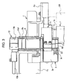
- the warp tension detection apparatus includes a tension roller 1 that serves as a tension detection roller, tension detection levers 3, and load cells 5 that serve as tension detectors.
- the tension detection levers 3 and the load cells 5 are provided at either end of the tension roller 1 in the weaving-width direction.
- the tension roller 1 includes shaft portions 1a at the ends thereof and is supported at the shaft portions 1a by respective loom frames F with the tension detection levers 3 interposed therebetween.
- the warp tension detection apparatus includes a pair of tension detection levers 3 supported by the respective loom frames F that are arranged with a gap therebetween in the weaving-width direction, and a pair of load cells 5 connected to the respective tension detection levers 3.
- the structures of the warp tension detection apparatus at both sides thereof in the weaving-width direction are similar to each other except that they are symmetrical in the weaving-width direction. Therefore, only the structure at one side of the apparatus is illustrated in Figs. 2 to 4 and will basically be described in detail in the following description.
- the tension detection lever 3 includes a cylindrical base portion 3a having a through hole 3a1 that extends in the axial direction.
- the tension detection lever 3 also includes two arm portions 3b and 3c that are formed integrally with the base portion 3a so as to project from an outer peripheral surface of the base portion 3a.
- the two arm portions 3b and 3c are disposed on either side of the axis of the through hole 3a1 and extend perpendicular to the axis.
- the loom frame F includes a frame body Fb and a support bracket Fa provided on the frame body Fb.
- a first shaft 7 is provided on the support bracket Fa of the loom frame F so as to project inward from an inner end surface of the support bracket Fa and extend parallel to the weaving-width direction.
- the tension detection lever 3 is rotatably supported by the first shaft 7 at the base portion 3a thereof with a bearing, such as a needle bearing, interposed between the tension detection lever 3 and the first shaft 7.
- the bearing includes an outer ring that is fitted to the through hole 3a1 in the base portion 3a and an inner ring that is fitted to a portion of the first shaft 7 that projects from the support bracket Fa.
- the tension detection lever 3 is supported by the support bracket Fa, the first shaft 7, and the bearing fitted to the first shaft 7 such that the tension detection lever 3 is rotatable with respect to the loom frame F.
- the loom frame F, the first shaft 7, and the tension detection lever 3 may instead be connected such that the first shaft 7 and the tension detection lever 3 are not rotatable with respect to each other and the first shaft 7 is supported by the loom frame F (support bracket Fa) with a bearing interposed therebetween.
- the arm portion 3b which is one of the two arm portions 3b and 3c of the tension detection lever 3 that extends downward, is connected to the load cell 5 at an end thereof.
- the load cell 5 includes an S-shaped load cell body 5a and connecting rods 5b attached to the load cell body 5a at the ends thereof in the direction in which the load is applied.
- One of the connecting rods 5b of the load cell 5 is connected to the arm portion 3b of the tension detection lever 3 with a spherical bearing interposed therebetween.
- the other one of the connecting rods 5b is supported by the support bracket Fa with a spherical bearing interposed therebetween.
- the tension detection lever 3 which is rotatably supported by the loom frame F (first shaft 7), is connected to the loom frame F at the arm portion 3b thereof with the load cell 5 interposed between the tension detection lever 3 and the loom frame F. Accordingly, the phase of the tension detection lever 3 around the axis of the first shaft 7 is fixed (maintained) by the load cell 5.
- the arm portion 3c which is one of the two arm portions 3b and 3c of the tension detection lever 3 that extends upward, includes a cylindrical end portion in the illustrated example.
- a through hole 3c1 is formed in the cylindrical end portion.
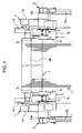
- a second shaft 9 is rotatably fitted to the through hole 3c1 in the arm portion 3c with a bearing Ba ( Fig. 3 ), such as a needle bearing, interposed therebetween.
- the bearing Ba serves as a first bearing.
- the second shaft 9 is rotatably supported by the arm portion 3c of the tension detection lever 3 with the bearing Ba interposed therebetween.
- the bearing Ba includes an inner ring that is fitted to the outer peripheral surface of the second shaft 9 and an outer ring that is fitted to the through hole 3c1 in the arm portion 3c of the tension detection lever 3.
- the phase of the tension detection lever 3 around the axis of the first shaft 7 is fixed (maintained) by the load cell 5. Therefore, the position of the through hole 3c1 in the tension detection lever 3 that supports the second shaft 9 around the axis of the first shaft 7 is also fixed.
- the second shaft 9 is supported by the tension detection lever 3 at the inner end thereof, and extends outward in the weaving-width direction from the support position thereof.
- a tension lever 11, which serves as a support lever, is fixed to the second shaft 9 at a position outside the position at which the second shaft 9 is supported by the tension detection lever 3 and between the tension detection lever 3 and the support bracket Fa.
- the second shaft 9 extends only outward from the position at which the second shaft 9 is supported by the tension detection lever 3, and the tension lever 11 is fixed to the second shaft 9 at a position outside the tension detection lever 3.
- the second shaft 9 may also extend inward from the support position thereof, and the tension lever 11 may be fixed to the second shaft 9 at a position inside the tension detection lever 3.
- the tension lever 11 includes two end portions having respective through holes.
- One of the end portions has a split clamping structure in which a slot that communicates with the through hole is formed at the rim and the diameter of the through hole can be reduced by fastening bolts 11a.
- the end portion of the tension lever 11 having the split clamping structure is fixed to the second shaft 9 such that the tension lever 11 is at a predetermined angle (approximately 90° in the illustrated example) with respect to the arm portion 3c of the tension detection lever 3.
- the other one of the end portions of the tension lever 11 has a bearing fitted to the through hole thereof, and the corresponding shaft portion 1a of the tension roller 1 is fitted to the end portion with the bearing interposed therebetween.
- the shaft portions 1a at the ends of the tension roller 1 are supported by the respective second shafts 9 with the tension levers 11 interposed therebetween.
- the phases of the tension detection levers 3, which are provided on the left and right loom frames F, around the first shafts 7 are fixed by the respective load cells 5 so that the through holes 3c1 in the arm portions 3c coincide with each other in side view. Therefore, the axial centers of the second shafts 9 provided on the respective loom frames F also coincide with each other in side view.
- the tension levers 11 are fixed to the respective second shafts 9 so that the tension levers 11 are at the same angle with respect to the respective tension detection levers 3 on the loom frames F at both sides. Therefore, the tension roller 1 is supported by the tension levers 11 so as to extend parallel to the first shafts 7 and the second shafts 9.
- a plurality of warp yarns T that are drawn out from a warp beam (not shown) in the form of a sheet and guided by a guide roller GR are wound around the tension roller 1.
- the load applied to the tension roller 1 owing to the tension of the warp yarns T is applied to the load cells 5 through the tension levers 11, the second shafts 9, and the tension detection levers 3.
- the load cells 5 detect the load applied thereto, and thus the tension of the warp yarns T is measured.
- the warp tension detection apparatus has the above-described basic structure.
- each second shaft 9, which is supported by the corresponding tension detection lever 3 and supports the tension roller 1 is supported also by the loom frame F, on which the tension detection lever 3 is supported, at a position different from the position at which the second shaft 9 is supported by the tension detection lever 3. This will be described in more detail.
- the second shaft 9 extends outward from the position at which it is supported by the tension detection lever 3.
- the second shaft 9 extends to a position outside the loom frame F.
- the support bracket Fa of the loom frame F has a through hole Fa1 at a position where the central axis of the through hole Fa1 substantially coincides with the central axis of the through hole 3c1 in the arm portion 3c of the tension detection lever 3.
- the second shaft 9 is inserted through the through hole Fa1 in the support bracket Fa and is fitted to a bearing Bb that is fitted an outer end portion of the through hole Fa1.
- the bearing Bb serves as a second bearing.
- the second shaft 9 is supported by the support bracket Fa with the bearing Bb interposed therebetween at the outer end of the second shaft 9 in the extending direction thereof.
- the second shaft 9 is supported by the tension detection lever 3 with the bearing Ba (first bearing) interposed therebetween at an end of a portion of the second shaft 9 that projects inward from the loom frame F (support bracket Fa), and is also supported by the loom frame F (support bracket Fa) with the bearing Bb (second bearing) interposed therebetween at a position near the outer end of the loom frame F in the weaving-width direction.
- the second shaft 9, which is supported by the tension detection lever 3 and supports the tension roller 1 is supported at two different positions, that is, positions near one and the other ends of the second shaft 9 in the extending direction thereof (axial direction).
- the tension detection lever 3 is supported at two positions, which are the position at which the tension detection lever 3 is supported by the first shaft 7 and the position at which the second shaft 9 is inserted through the tension detection lever 3.
- the warp tension detection apparatus includes the support structure in which the second shaft 9, which supports the tension roller 1 that serves as the tension detection roller, and the tension detection lever 3, which is included in a tension detection mechanism, are supported by the loom frame F in the above-described manner.
- the overall support rigidity of the loom frame F of the apparatus is increased, and the risk of damage of the apparatus can be reduced compared to that of the apparatus of the related art.
- the overall support rigidity of the apparatus is increased, vibration of the tension detection apparatus due to vibration of the loom in the weaving operation can be suppressed, and the influence of load (disturbance load) caused by the vibration on the tension detection operation can be reduced.
- an easing mechanism 13 which causes the tension roller 1 to perform an easing motion, is connected to the second shaft 9 at a position outside the loom frame F, more specifically, at a position outside the position at which the second shaft 9 is supported by the loom frame F (support bracket Fa). This will be described in more detail.
- the second shaft 9 is formed so as to project outward from the loom frame F (support bracket Fa).
- the length of the second shaft 9 is such that the second shaft 9 extends from the position at which it is supported by the tension detection lever 3 to a position outside the loom frame F.
- a portion of the second shaft 9 that projects from the loom frame F is connected to an easing lever 13a of the easing mechanism 13.
- the easing lever 13a is connected to the second shaft 9 such that the easing lever 13a extends vertically, and is fixed to the second shaft 9 by a split clamping structure formed at the top end of the easing lever 13a.
- the bottom end of the easing lever 13a is connected to a first end of an easing rod 13b with a bearing, such as a spherical bearing, interposed therebetween.
- the easing rod 13b extends in the front-rear direction, which is the direction in which the warp yarns T extend from the tension roller 1 to the cloth fell.
- a second end of the easing rod 13b is connected to a drive device (not shown) that reciprocates the easing rod 13b in the front-rear direction.
- the drive device is, for example, a crank-type drive device including a drive shaft and a crank lever.
- the drive shaft is supported by the loom frame F and rotated by a main shaft of the loom that serves as a drive source.
- the crank lever is attached to the drive shaft and connected to the second end of the easing rod 13b at a position displaced from the axial center of the drive shaft.
- the second shaft 9, to which the easing lever 13a is fixed rotates in a reciprocating manner within an angle range that corresponds to the amount by which the easing lever 13a swings.
- the tension lever 11, which is fixed to the second shaft 9 at one end thereof swings around the axial center of the second shaft 9 in a reciprocating manner, thereby causing the tension roller 1, which is supported by the tension lever 11 at the other end thereof, to perform the easing motion.
- the tension detection lever 3 and the easing mechanism 13 are connected to the second shaft 9 at the inner side (tension-roller side) and the outer side (side opposite to the tension-roller side), respectively, of the position at which the second shaft 9 is supported by the loom frame F.
- the tension detection mechanism which includes the load cell 5 and the tension detection lever 3 that supports the second shaft 9 to which the load is applied, and the easing mechanism 13, which causes the tension roller 1 to perform the easing motion, are disposed at either side of the position at which the second shaft 9 is supported by the loom frame F.
- the load that is applied to the second shaft 9 owing to the movement of the easing mechanism 13 and that serves as a disturbance component (disturbance load) in the total load applied to the load cell 5 is received by the loom frame F.
- the disturbance load applied to the load cell 5 can be reduced and the signal-to-noise (S/N) ratio of a tension detection signal output from the load cell 5 can be increased.
- the tension detection mechanism is disposed at the tension-roller-1 side of the position at which the second shaft 9 is supported by the loom frame F. Accordingly, the percentage of the load due to the tension of the warp yarns T in the total load applied to the load cell 5 can be increased. As a result, the S/N ratio of the tension detection signal can be further increased.
- the above-described easing mechanism 13 is an active easing mechanism in which the easing rod 13b is connected to the drive device and is actively reciprocated in the front-rear direction.
- the easing mechanism 13 may instead be a passive easing mechanism in which the easing rod 13b is supported by the loom frame F with a spring interposed therebetween.
- the tension detection mechanism which includes the load cell 5 and the tension detection lever 3 that supports the second shaft 9 to which the load is applied, is provided on each of the left and right loom frames F, and the warp tension detection apparatus includes a pair of tension detection levers 3 and a pair of load cells 5.
- the warp tension detection apparatus may instead be such that the tension detection mechanism is provided on only one of the loom frames F.
- the tension detection lever 3 is provided only at one of the ends of the tension roller 1.
- the second shaft 9 is supported only by the loom frame F and the end portion of the tension roller 1 is supported by the second shaft 9 with the tension lever 11 interposed therebetween.
- each of the tension detection levers 3 provided on the left and right loom frames F is connected to the load cell 5.
- the load cell 5 may instead be connected to the arm portion 3b of only one of the tension detection levers 3 while the arm portions 3b of the tension detection levers 3 are connected to each other at the ends thereof with a connection rod.
- a single second shaft 9 that extends in the weaving-width direction may be used instead.
- the second shaft 9 can be supported at least at three positions by the loom frames F at either side of the loom and the tension detection lever 3. Therefore, the overall support rigidity of the apparatus can be further increased.
- the apparatus may be structured such that the easing mechanism 13 is provided on only one of the loom frames F at both sides of the loom and is connected to one end of the second shaft 9.
- the easing mechanism 13 is connected to the second shaft 9 at the outer side (side opposite to the tension-roller-1 side) of the support position at which the second shaft 9 is supported by the loom frame F, and the tension detection mechanism is connected to the second shaft 9 at the inner side (tension-roller-1 side) of the support position.
- the easing mechanism 13 may instead be connected to the second shaft 9 at the inner side of the support position while the tension detection mechanism is connected to the second shaft 9 at the outer side of the support position.
- the easing mechanism 13 and the tension detection mechanism may both be connected to the second shaft 9 at the inner side or the outer side of the support position.
- the position at which the tension roller 1 is supported by the second shaft 9, that is, the position at which the tension lever 11 is supported by the second shaft 9, is inside the loom frame F in the present embodiment.
- the tension roller 1 may instead be supported by the second shaft 9 at a position outside the loom frame F. More specifically, the position at which the second shaft 9 is supported by the tension detection lever 3 (position of the first bearing Ba), the position at which the second shaft 9 supports the tension roller 1 (position at which the tension lever 11 is fixed), and the position at which the second shaft 9 is supported by the loom frame F (position of the second bearing Bb) may be arranged reversely to the arrangement in the present embodiment.
- the position at which the second shaft 9 is supported by the loom frame F, the position at which the second shaft 9 supports the tension roller 1, and the position at which the second shaft 9 is supported by the tension detection lever 3 may be arranged in that order from the inner side in the weaving-width direction.
- the position at which the second shaft 9 supports the tension roller 1 may be located at the outermost position. In the case where the tension roller 1 is supported outside the loom frame F, it is necessary that the loom frame F (support bracket Fa) be shaped so as to allow the easing motion of the tension roller 1.
- the position at which the easing mechanism 13 (easing lever 13a) is connected to the second shaft 9 is different from the support position of the tension roller 1 (position at which the tension lever 11 is connected to the second shaft 9).
- the tension lever 11 swings in a reciprocating manner, thereby causing the tension roller 1 to perform the easing motion.
- the easing mechanism may be connected to the tension lever 11 so as to directly swing the tension lever 11 in a reciprocating manner without the second shaft 9 interposed therebetween.
- Fig. 5A illustrates a warp tension detection apparatus viewed through a support bracket Fa from the inside of a loom frame F.
- Fig. 5B is a partially sectioned plan view of Fig. 5A in which parts including the part at which the second shaft 9 is supported by the support bracket Fa are sectioned.
- a tension lever 11' includes a support portion 11b that supports a tension roller 1 and an extending portion 11c that extends downward from the support portion 11b (see Fig. 5A ).
- the support portion 11b corresponds to the tension lever 11 in the example of Figs. 1 to 4 .
- the tension lever 11' is connected to an easing rod 13b of an easing mechanism at the bottom end of the extending portion 11c.
- the extending portion 11c of the tension lever 11' corresponds to the easing lever 13a in the example illustrated in Figs. 1 to 4 .
- the easing mechanism is arranged on the same side (outer side in the example illustrated in Figs. 5A and 5B ) of the loom frame F as the position at which the second shaft 9 supports the tension roller 1.
- the tension lever and the easing lever are integrated together.
- the second shaft 9 which is supported by a tension detection lever 3 and supports the tension lever 11', extends inward from the position at which the second shaft 9 is supported by the tension detection lever 3 in the weaving-width direction.
- the second shaft 9 is supported by the support bracket Fa with a bearing (needle bearing Bc in the illustrated example) interposed therebetween at the position of the loom frame F in the weaving-width direction.
- the second shaft 9 is rotatably supported by the tension detection lever 3 with a bearing metal Bd interposed therebetween, and supports the tension lever 11' in a non-rotatable manner.
- the second shaft 9 may be non-rotatable if the tension lever 11' is supported in a manner such that the tension lever 11' is rotatable with respect to the second shaft 9.
- the second shaft 9 may be non-rotatably supported by the loom frame F.
- the second shaft 9 and the tension detection lever 3 may be connected to each other such that they are not rotatable with respect to each other.
- the tension detection apparatus for a loom according to the present invention is used as a warp tension detection apparatus at a let-off side of a loom in which the tension detection roller is a tension roller that performs the easing motion.
- Other embodiments (or modifications) of the tension detection apparatus for a loom according to the present invention will now be described.
- the tension detection roller In the case where the guide roller that guides the warp yarns or woven cloth in a stationary state is used as the tension detection roller as described above, it is not necessary that the tension detection roller be supported at a position displaced from the axial center of the second shaft as in the case of the tension roller according to the above-described embodiment.
- the tension detection roller may instead be supported coaxially with the second shaft.
- the second shaft and the tension detection roller may be connected to each other such that the axial centers thereof coincide with each other.
- the tension detection roller may have a shaft portion that functions as the second shaft.
- a tension detection lever 3' may include a single arm portion 3d.
- a support portion having a through hole 3d1 is provided near a middle portion of the arm portion 3d, and a second shaft 9 is supported by the support portion.
- One end of a tension detector (load cell 5) is connected to the distal end of a portion of the arm portion 3d that extends beyond the support portion.
- a tension detection lever 3'' may include a single arm portion 3e. Similar to the above-described embodiment, a support portion having a through hole 3e1 is provided at the distal end of the arm portion 3e, and a second shaft 9 is supported by the support portion.
- One end of a tension detector (load cell 5) is connected to the arm portion 3e at a position between the base portion 3a and the support portion.
- the support positions are not limited to the outer side (side opposite to the tension-detection-roller side) of the position at which the second shaft is supported by the tension detection lever as in the above-described embodiment.
- the support positions may instead be at the inner side (tension-detection-roller side) of the position at which the second shaft is supported by the tension detection lever.
- the second shaft may be supported by the loom frame at both sides of the position at which the second shaft is supported by the tension detection lever, and moreover, at two or more positions at each side (in particular, the outer side) of the position at the second shaft is supported by the tension detection lever.
- the load applied to the tension detection lever (tension detector) owing to the tension of the object to be detected is reduced compared to that in the case in which the position at which the second shaft is supported by the tension detection lever is on the tension-detection-roller side of the position at which the second shaft is supported by the loom frame.
- the load applied to the tension detection lever (tension detector) owing to the tension of the object to be detected is further reduced.
- the component of the detection signal obtained by the tension detector that corresponds to the tension of the warp yarns is reduced (S/N ratio is reduced) and there is a risk that the accuracy of tension detection will be reduced.
- the number of positions at which the second shaft is supported by the loom frame is preferably one or less at the tension-detection-roller side of the position at which the second shaft is supported by the tension detection lever.
- the tension detection roller may be supported by the second shaft by using a support lever at a position between the positions at which the second shaft is supported by the loom frame. In such a case, the overall support rigidity of the apparatus can be increased.
- the position at which the second shaft is supported by the tension detection lever and the position at which the second shaft supports the tension detection roller can be arranged without any of the positions at which the second shaft is supported by the loom frame interposed therebetween. This structure is also advantageous in performing tension detection.
Landscapes
- Engineering & Computer Science (AREA)
- Textile Engineering (AREA)
- Looms (AREA)
Applications Claiming Priority (1)
| Application Number | Priority Date | Filing Date | Title |
|---|---|---|---|
| JP2011229500A JP5778544B2 (ja) | 2011-10-19 | 2011-10-19 | 織機の張力検出装置 |
Publications (3)
| Publication Number | Publication Date |
|---|---|
| EP2584079A2 EP2584079A2 (en) | 2013-04-24 |
| EP2584079A3 EP2584079A3 (en) | 2013-11-13 |
| EP2584079B1 true EP2584079B1 (en) | 2014-12-03 |
Family
ID=47323804
Family Applications (1)
| Application Number | Title | Priority Date | Filing Date |
|---|---|---|---|
| EP12006669.1A Active EP2584079B1 (en) | 2011-10-19 | 2012-09-24 | Loom comprising a tension detection apparatus |
Country Status (3)
| Country | Link |
|---|---|
| EP (1) | EP2584079B1 (ja) |
| JP (1) | JP5778544B2 (ja) |
| CN (1) | CN103061011B (ja) |
Families Citing this family (7)
| Publication number | Priority date | Publication date | Assignee | Title |
|---|---|---|---|---|
| DE102013222679A1 (de) * | 2013-11-07 | 2015-05-07 | Lindauer Dornier Gesellschaft Mit Beschränkter Haftung | Verfahren zum Messen der Gewebespannung in einer Webmaschine |
| CN103820928B (zh) * | 2014-03-11 | 2015-02-11 | 长兴圣帆纺织有限公司 | 一种用于喷气织机的新型张力控制仪 |
| JP6347981B2 (ja) * | 2014-04-24 | 2018-06-27 | 津田駒工業株式会社 | 織機におけるイージングロールの退避装置 |
| DE102016220546B3 (de) * | 2016-10-20 | 2017-11-16 | Lindauer Dornier Gesellschaft Mit Beschränkter Haftung | Vorrichtung zur Messung der Kettspannung in einer Webmaschine sowie Webmaschine mit einer derartigen Vorrichtung |
| CN112363548B (zh) * | 2020-10-22 | 2023-07-14 | 昆山市奋发绝缘材料有限公司 | 一种导铺辊及其加工工艺 |
| CN112697330B (zh) * | 2020-12-16 | 2022-07-26 | 安徽博润纺织品有限公司 | 一种高张力聚酯筛网的生产工艺 |
| CN113882068B (zh) * | 2021-11-22 | 2023-02-10 | 绍兴柯桥宽庭纺织品有限公司 | 一种家纺布织造用张力可调剑杆机 |
Family Cites Families (9)
| Publication number | Priority date | Publication date | Assignee | Title |
|---|---|---|---|---|
| CH635627A5 (de) * | 1979-03-01 | 1983-04-15 | Sulzer Ag | Vorrichtung zur verstellung der spannung eines spannbaumes einer webmaschine. |
| JPH0551845A (ja) * | 1991-08-12 | 1993-03-02 | Toyota Autom Loom Works Ltd | 織機における経糸張力検出方法及び装置 |
| JP2534202Y2 (ja) * | 1991-12-13 | 1997-04-30 | 株式会社豊田自動織機製作所 | 織機における経糸張力検出装置 |
| JP3374450B2 (ja) * | 1993-07-26 | 2003-02-04 | 株式会社豊田自動織機 | 織機における経糸張力検出装置 |
| JP3533165B2 (ja) * | 2000-09-25 | 2004-05-31 | 津田駒工業株式会社 | 糸シート巻取機 |
| CN2444973Y (zh) * | 2000-09-26 | 2001-08-29 | 上海太平洋印染机械有限公司 | 丝光机织物张力控制装置 |
| JP2004250817A (ja) * | 2003-02-19 | 2004-09-09 | Toyota Industries Corp | 織機における経糸張力検出装置 |
| JP2005240206A (ja) * | 2004-02-25 | 2005-09-08 | Tsudakoma Corp | 織機の送出装置 |
| JP4955325B2 (ja) * | 2006-07-11 | 2012-06-20 | 津田駒工業株式会社 | 織機のロールの支持装置 |
-
2011
- 2011-10-19 JP JP2011229500A patent/JP5778544B2/ja active Active
-
2012
- 2012-09-24 EP EP12006669.1A patent/EP2584079B1/en active Active
- 2012-10-12 CN CN201210387838.1A patent/CN103061011B/zh active Active
Also Published As
| Publication number | Publication date |
|---|---|
| CN103061011A (zh) | 2013-04-24 |
| JP5778544B2 (ja) | 2015-09-16 |
| JP2013087394A (ja) | 2013-05-13 |
| CN103061011B (zh) | 2015-05-27 |
| EP2584079A2 (en) | 2013-04-24 |
| EP2584079A3 (en) | 2013-11-13 |
Similar Documents
| Publication | Publication Date | Title |
|---|---|---|
| EP2584079B1 (en) | Loom comprising a tension detection apparatus | |
| JP5344889B2 (ja) | 積極イージング機構を用いた織機の送出装置 | |
| JP4851098B2 (ja) | 連続繊維束のガイド装置 | |
| JP6086882B2 (ja) | 糸供給システム | |
| JP4955325B2 (ja) | 織機のロールの支持装置 | |
| CN101105421A (zh) | 消极式凸轮开口机构的动态模拟振动测量装置 | |
| JP6277006B2 (ja) | 織機における経糸屈曲装置 | |
| CN103898668B (zh) | 一种喷气织机送经装置 | |
| EP1950332A1 (en) | Drive-amount changing mechanism in crank-type driver | |
| EP2194176A2 (en) | Pile fabric loom having pile warp tension adjuster | |
| JP2004250817A (ja) | 織機における経糸張力検出装置 | |
| EP2937451B1 (en) | Easing roller retracting device for loom | |
| US3949788A (en) | Web weaving machine with several heald shafts | |
| CN203807667U (zh) | 一种喷气织机送经装置 | |
| JPH0551988U (ja) | 織機における経糸張力検出装置 | |
| KR102637289B1 (ko) | 와인딩 머신 | |
| CN101597832B (zh) | 织机的张力辊支撑机构 | |
| CN108914337B (zh) | 一种两级缓冲积极式绒经送经机构 | |
| CN217478761U (zh) | 一种收卷张力调节装置 | |
| JP5738612B2 (ja) | 巻糸装置 | |
| CN114808266B (zh) | 一种新型连续性调节纱线张力平衡的装置 | |
| JP2003286632A (ja) | 織機における経糸張力調整装置 | |
| JPH0210140Y2 (ja) | ||
| EP3022345B1 (en) | Back rest device for a weaving machine | |
| JPH055250A (ja) | 織機における経糸張力調整装置 |
Legal Events
| Date | Code | Title | Description |
|---|---|---|---|
| PUAI | Public reference made under article 153(3) epc to a published international application that has entered the european phase |
Free format text: ORIGINAL CODE: 0009012 |
|
| AK | Designated contracting states |
Kind code of ref document: A2 Designated state(s): AL AT BE BG CH CY CZ DE DK EE ES FI FR GB GR HR HU IE IS IT LI LT LU LV MC MK MT NL NO PL PT RO RS SE SI SK SM TR |
|
| AX | Request for extension of the european patent |
Extension state: BA ME |
|
| PUAL | Search report despatched |
Free format text: ORIGINAL CODE: 0009013 |
|
| AK | Designated contracting states |
Kind code of ref document: A3 Designated state(s): AL AT BE BG CH CY CZ DE DK EE ES FI FR GB GR HR HU IE IS IT LI LT LU LV MC MK MT NL NO PL PT RO RS SE SI SK SM TR |
|
| AX | Request for extension of the european patent |
Extension state: BA ME |
|
| RIC1 | Information provided on ipc code assigned before grant |
Ipc: D03D 49/12 20060101AFI20131007BHEP |
|
| 17P | Request for examination filed |
Effective date: 20140326 |
|
| RBV | Designated contracting states (corrected) |
Designated state(s): AL AT BE BG CH CY CZ DE DK EE ES FI FR GB GR HR HU IE IS IT LI LT LU LV MC MK MT NL NO PL PT RO RS SE SI SK SM TR |
|
| GRAP | Despatch of communication of intention to grant a patent |
Free format text: ORIGINAL CODE: EPIDOSNIGR1 |
|
| INTG | Intention to grant announced |
Effective date: 20140624 |
|
| GRAS | Grant fee paid |
Free format text: ORIGINAL CODE: EPIDOSNIGR3 |
|
| GRAA | (expected) grant |
Free format text: ORIGINAL CODE: 0009210 |
|
| AK | Designated contracting states |
Kind code of ref document: B1 Designated state(s): AL AT BE BG CH CY CZ DE DK EE ES FI FR GB GR HR HU IE IS IT LI LT LU LV MC MK MT NL NO PL PT RO RS SE SI SK SM TR |
|
| REG | Reference to a national code |
Ref country code: GB Ref legal event code: FG4D |
|
| REG | Reference to a national code |
Ref country code: AT Ref legal event code: REF Ref document number: 699450 Country of ref document: AT Kind code of ref document: T Effective date: 20141215 Ref country code: CH Ref legal event code: EP |
|
| REG | Reference to a national code |
Ref country code: IE Ref legal event code: FG4D |
|
| REG | Reference to a national code |
Ref country code: DE Ref legal event code: R096 Ref document number: 602012004030 Country of ref document: DE Effective date: 20150115 |
|
| REG | Reference to a national code |
Ref country code: NL Ref legal event code: VDEP Effective date: 20141203 |
|
| REG | Reference to a national code |
Ref country code: AT Ref legal event code: MK05 Ref document number: 699450 Country of ref document: AT Kind code of ref document: T Effective date: 20141203 |
|
| PG25 | Lapsed in a contracting state [announced via postgrant information from national office to epo] |
Ref country code: NO Free format text: LAPSE BECAUSE OF FAILURE TO SUBMIT A TRANSLATION OF THE DESCRIPTION OR TO PAY THE FEE WITHIN THE PRESCRIBED TIME-LIMIT Effective date: 20150303 Ref country code: LT Free format text: LAPSE BECAUSE OF FAILURE TO SUBMIT A TRANSLATION OF THE DESCRIPTION OR TO PAY THE FEE WITHIN THE PRESCRIBED TIME-LIMIT Effective date: 20141203 Ref country code: NL Free format text: LAPSE BECAUSE OF FAILURE TO SUBMIT A TRANSLATION OF THE DESCRIPTION OR TO PAY THE FEE WITHIN THE PRESCRIBED TIME-LIMIT Effective date: 20141203 Ref country code: ES Free format text: LAPSE BECAUSE OF FAILURE TO SUBMIT A TRANSLATION OF THE DESCRIPTION OR TO PAY THE FEE WITHIN THE PRESCRIBED TIME-LIMIT Effective date: 20141203 Ref country code: FI Free format text: LAPSE BECAUSE OF FAILURE TO SUBMIT A TRANSLATION OF THE DESCRIPTION OR TO PAY THE FEE WITHIN THE PRESCRIBED TIME-LIMIT Effective date: 20141203 |
|
| REG | Reference to a national code |
Ref country code: LT Ref legal event code: MG4D |
|
| PG25 | Lapsed in a contracting state [announced via postgrant information from national office to epo] |
Ref country code: RS Free format text: LAPSE BECAUSE OF FAILURE TO SUBMIT A TRANSLATION OF THE DESCRIPTION OR TO PAY THE FEE WITHIN THE PRESCRIBED TIME-LIMIT Effective date: 20141203 Ref country code: AT Free format text: LAPSE BECAUSE OF FAILURE TO SUBMIT A TRANSLATION OF THE DESCRIPTION OR TO PAY THE FEE WITHIN THE PRESCRIBED TIME-LIMIT Effective date: 20141203 Ref country code: HR Free format text: LAPSE BECAUSE OF FAILURE TO SUBMIT A TRANSLATION OF THE DESCRIPTION OR TO PAY THE FEE WITHIN THE PRESCRIBED TIME-LIMIT Effective date: 20141203 Ref country code: LV Free format text: LAPSE BECAUSE OF FAILURE TO SUBMIT A TRANSLATION OF THE DESCRIPTION OR TO PAY THE FEE WITHIN THE PRESCRIBED TIME-LIMIT Effective date: 20141203 Ref country code: SE Free format text: LAPSE BECAUSE OF FAILURE TO SUBMIT A TRANSLATION OF THE DESCRIPTION OR TO PAY THE FEE WITHIN THE PRESCRIBED TIME-LIMIT Effective date: 20141203 Ref country code: GR Free format text: LAPSE BECAUSE OF FAILURE TO SUBMIT A TRANSLATION OF THE DESCRIPTION OR TO PAY THE FEE WITHIN THE PRESCRIBED TIME-LIMIT Effective date: 20150304 Ref country code: CY Free format text: LAPSE BECAUSE OF FAILURE TO SUBMIT A TRANSLATION OF THE DESCRIPTION OR TO PAY THE FEE WITHIN THE PRESCRIBED TIME-LIMIT Effective date: 20141203 |
|
| PG25 | Lapsed in a contracting state [announced via postgrant information from national office to epo] |
Ref country code: SK Free format text: LAPSE BECAUSE OF FAILURE TO SUBMIT A TRANSLATION OF THE DESCRIPTION OR TO PAY THE FEE WITHIN THE PRESCRIBED TIME-LIMIT Effective date: 20141203 Ref country code: CZ Free format text: LAPSE BECAUSE OF FAILURE TO SUBMIT A TRANSLATION OF THE DESCRIPTION OR TO PAY THE FEE WITHIN THE PRESCRIBED TIME-LIMIT Effective date: 20141203 Ref country code: RO Free format text: LAPSE BECAUSE OF FAILURE TO SUBMIT A TRANSLATION OF THE DESCRIPTION OR TO PAY THE FEE WITHIN THE PRESCRIBED TIME-LIMIT Effective date: 20141203 Ref country code: EE Free format text: LAPSE BECAUSE OF FAILURE TO SUBMIT A TRANSLATION OF THE DESCRIPTION OR TO PAY THE FEE WITHIN THE PRESCRIBED TIME-LIMIT Effective date: 20141203 Ref country code: PT Free format text: LAPSE BECAUSE OF FAILURE TO SUBMIT A TRANSLATION OF THE DESCRIPTION OR TO PAY THE FEE WITHIN THE PRESCRIBED TIME-LIMIT Effective date: 20150403 |
|
| PG25 | Lapsed in a contracting state [announced via postgrant information from national office to epo] |
Ref country code: PL Free format text: LAPSE BECAUSE OF FAILURE TO SUBMIT A TRANSLATION OF THE DESCRIPTION OR TO PAY THE FEE WITHIN THE PRESCRIBED TIME-LIMIT Effective date: 20141203 Ref country code: IS Free format text: LAPSE BECAUSE OF FAILURE TO SUBMIT A TRANSLATION OF THE DESCRIPTION OR TO PAY THE FEE WITHIN THE PRESCRIBED TIME-LIMIT Effective date: 20150403 |
|
| REG | Reference to a national code |
Ref country code: DE Ref legal event code: R097 Ref document number: 602012004030 Country of ref document: DE |
|
| PLBE | No opposition filed within time limit |
Free format text: ORIGINAL CODE: 0009261 |
|
| STAA | Information on the status of an ep patent application or granted ep patent |
Free format text: STATUS: NO OPPOSITION FILED WITHIN TIME LIMIT |
|
| PG25 | Lapsed in a contracting state [announced via postgrant information from national office to epo] |
Ref country code: DK Free format text: LAPSE BECAUSE OF FAILURE TO SUBMIT A TRANSLATION OF THE DESCRIPTION OR TO PAY THE FEE WITHIN THE PRESCRIBED TIME-LIMIT Effective date: 20141203 |
|
| 26N | No opposition filed |
Effective date: 20150904 |
|
| PG25 | Lapsed in a contracting state [announced via postgrant information from national office to epo] |
Ref country code: SI Free format text: LAPSE BECAUSE OF FAILURE TO SUBMIT A TRANSLATION OF THE DESCRIPTION OR TO PAY THE FEE WITHIN THE PRESCRIBED TIME-LIMIT Effective date: 20141203 |
|
| PG25 | Lapsed in a contracting state [announced via postgrant information from national office to epo] |
Ref country code: MC Free format text: LAPSE BECAUSE OF FAILURE TO SUBMIT A TRANSLATION OF THE DESCRIPTION OR TO PAY THE FEE WITHIN THE PRESCRIBED TIME-LIMIT Effective date: 20141203 Ref country code: LU Free format text: LAPSE BECAUSE OF FAILURE TO SUBMIT A TRANSLATION OF THE DESCRIPTION OR TO PAY THE FEE WITHIN THE PRESCRIBED TIME-LIMIT Effective date: 20150924 |
|
| REG | Reference to a national code |
Ref country code: CH Ref legal event code: PL |
|
| REG | Reference to a national code |
Ref country code: IE Ref legal event code: MM4A |
|
| REG | Reference to a national code |
Ref country code: FR Ref legal event code: ST Effective date: 20160531 |
|
| PG25 | Lapsed in a contracting state [announced via postgrant information from national office to epo] |
Ref country code: LI Free format text: LAPSE BECAUSE OF NON-PAYMENT OF DUE FEES Effective date: 20150930 Ref country code: CH Free format text: LAPSE BECAUSE OF NON-PAYMENT OF DUE FEES Effective date: 20150930 Ref country code: IE Free format text: LAPSE BECAUSE OF NON-PAYMENT OF DUE FEES Effective date: 20150924 |
|
| PG25 | Lapsed in a contracting state [announced via postgrant information from national office to epo] |
Ref country code: FR Free format text: LAPSE BECAUSE OF NON-PAYMENT OF DUE FEES Effective date: 20150930 |
|
| PG25 | Lapsed in a contracting state [announced via postgrant information from national office to epo] |
Ref country code: MT Free format text: LAPSE BECAUSE OF FAILURE TO SUBMIT A TRANSLATION OF THE DESCRIPTION OR TO PAY THE FEE WITHIN THE PRESCRIBED TIME-LIMIT Effective date: 20141203 |
|
| GBPC | Gb: european patent ceased through non-payment of renewal fee |
Effective date: 20160924 |
|
| PG25 | Lapsed in a contracting state [announced via postgrant information from national office to epo] |
Ref country code: HU Free format text: LAPSE BECAUSE OF FAILURE TO SUBMIT A TRANSLATION OF THE DESCRIPTION OR TO PAY THE FEE WITHIN THE PRESCRIBED TIME-LIMIT; INVALID AB INITIO Effective date: 20120924 Ref country code: BG Free format text: LAPSE BECAUSE OF FAILURE TO SUBMIT A TRANSLATION OF THE DESCRIPTION OR TO PAY THE FEE WITHIN THE PRESCRIBED TIME-LIMIT Effective date: 20141203 Ref country code: SM Free format text: LAPSE BECAUSE OF FAILURE TO SUBMIT A TRANSLATION OF THE DESCRIPTION OR TO PAY THE FEE WITHIN THE PRESCRIBED TIME-LIMIT Effective date: 20141203 |
|
| PG25 | Lapsed in a contracting state [announced via postgrant information from national office to epo] |
Ref country code: GB Free format text: LAPSE BECAUSE OF NON-PAYMENT OF DUE FEES Effective date: 20160924 |
|
| PG25 | Lapsed in a contracting state [announced via postgrant information from national office to epo] |
Ref country code: TR Free format text: LAPSE BECAUSE OF FAILURE TO SUBMIT A TRANSLATION OF THE DESCRIPTION OR TO PAY THE FEE WITHIN THE PRESCRIBED TIME-LIMIT Effective date: 20141203 |
|
| PG25 | Lapsed in a contracting state [announced via postgrant information from national office to epo] |
Ref country code: MK Free format text: LAPSE BECAUSE OF FAILURE TO SUBMIT A TRANSLATION OF THE DESCRIPTION OR TO PAY THE FEE WITHIN THE PRESCRIBED TIME-LIMIT Effective date: 20141203 |
|
| PG25 | Lapsed in a contracting state [announced via postgrant information from national office to epo] |
Ref country code: AL Free format text: LAPSE BECAUSE OF FAILURE TO SUBMIT A TRANSLATION OF THE DESCRIPTION OR TO PAY THE FEE WITHIN THE PRESCRIBED TIME-LIMIT Effective date: 20141203 |
|
| PGFP | Annual fee paid to national office [announced via postgrant information from national office to epo] |
Ref country code: IT Payment date: 20230810 Year of fee payment: 12 |
|
| PGFP | Annual fee paid to national office [announced via postgrant information from national office to epo] |
Ref country code: DE Payment date: 20230802 Year of fee payment: 12 Ref country code: BE Payment date: 20230818 Year of fee payment: 12 |