EP2580379B1 - Webmaschine zur herstellung von webgut mit einem eingearbeiteten legefaden - Google Patents
Webmaschine zur herstellung von webgut mit einem eingearbeiteten legefaden Download PDFInfo
- Publication number
- EP2580379B1 EP2580379B1 EP11725060.5A EP11725060A EP2580379B1 EP 2580379 B1 EP2580379 B1 EP 2580379B1 EP 11725060 A EP11725060 A EP 11725060A EP 2580379 B1 EP2580379 B1 EP 2580379B1
- Authority
- EP
- European Patent Office
- Prior art keywords
- warp
- laying
- shed
- threads
- thread
- Prior art date
- Legal status (The legal status is an assumption and is not a legal conclusion. Google has not performed a legal analysis and makes no representation as to the accuracy of the status listed.)
- Active
Links
Images



Classifications
-
- D—TEXTILES; PAPER
- D03—WEAVING
- D03D—WOVEN FABRICS; METHODS OF WEAVING; LOOMS
- D03D31/00—Lappet, swivel or other looms for forming embroidery-like decoration on fabrics
-
- D—TEXTILES; PAPER
- D03—WEAVING
- D03D—WOVEN FABRICS; METHODS OF WEAVING; LOOMS
- D03D35/00—Smallware looms, i.e. looms for weaving ribbons or other narrow fabrics
-
- D—TEXTILES; PAPER
- D03—WEAVING
- D03D—WOVEN FABRICS; METHODS OF WEAVING; LOOMS
- D03D41/00—Looms not otherwise provided for, e.g. for weaving chenille yarn; Details peculiar to these looms
Definitions
- the invention relates to a loom for the production of woven fabric with an incorporated laying thread.
- a weaving machine of the type mentioned is from the CH 490 541 known. There fastening threads are arranged by means of feeding needles during the weaving of a band. There are no indications as to how the needle loom could advantageously perform the weaving in of a conductor thread, in particular of an antenna thread. A similar technology became independent in the US 3,796,234 disclosed.
- the JP 2005/015954 A From the JP 2005/015954 A is a weaving machine for weaving an effect thread known, which can be incorporated into the ground fabric or rests on the ground fabric.
- the loom of the JP 2005/015954 A is equipped with a warp shed forming apparatus which allows individual warp yarns to be selected.
- the effect thread is a selected, additional warp thread. Both the effect thread and additional warp threads are guided within the shed. This has the consequence that the effect threads of the warp, which is supplied from above the additional warp threads and the selected effect thread, are tied off from these warp threads during a transverse movement of the effect threads. This means that the effect threads are not above the Basic tissues are attached, but become part of the basic tissue and thus change the structure.
- the object of the invention is to provide a loom which is suitable for the production of woven fabric with a trained-in laying thread.
- the machine should be suitable for applying a load on a Webgut, without significantly changing the Webgut.
- the object is achieved by the machine according to claim 1 in the loom mentioned above.
- the measures of the invention initially have the result that a laying thread can also be tied off in a transverse movement of the lining yarn guide - in the weft direction. Furthermore - and this is particularly advantageous - by the distribution of the movements, namely the tying and the shot - on two movements no ligation on the fabric side of the tape fabric visible.
- the machine in contrast to the weaving machine JP 2005/015954 A - able to apply a laying thread without noticeably altering the weaving material.
- the weaving machine in addition to and independent of the laying device for the at least one laying thread, has a warp laying device with a multiplicity of side-by-side warp laying elements for laying additional warp threads, the disadvantage of JP 2005/015954 A avoided that the filaments become part of the basic tissue and thus change the structure.
- the laying yarn can be moved and laid in any laying position between the warp-laying members on the tape fabric.
- Kettlegevoroplasty has transverse movement means by means of which it is movable transversely to the warp threads when it is not immersed in the shed.
- the laying device has at least one further laying yarn guide, which is arranged in the warp direction behind said laying yarn guide and is movable transversely to the warp direction.
- the device has at least one retaining hook which can hold the laying thread when the reed is bruised.
- the retaining hook is guided so that it is movable away from the tape fabric in an initial position after the laying of the load.
- the inventive technique can advantageously be used in that several Kettlegevoriquesen are arranged parallel to the selvedge side by side at a defined distance.
- the Kettlegevoriquesen are driven coupled.
- individual drives are provided, so that the Kettlegevortechniken are driven individually and independently controlled.
- FIG. 1 shows a loom according to a first embodiment of the present invention, as a schematic representation for explaining the basic movement.
- the warp threads 2 for producing a tape fabric 10 form for entry of a weft thread by means of a weft insertion needle 7 or a gripper - in a rapier - a top compartment 5 and a lower compartment 4.
- a reed 1 is arranged in a conventional manner to the registered weft threads to the already created Webgut 10 to strike.
- the Kettlegevorides 9 dives through the upper compartment 5 in the lower compartment 4 a. At the same time, the reed 1 moves backwards. The Kettlegevorides 9 can be moved in the direction of reed 1 as well as down in the lower compartment 4 become. The Kettlegevorides 9 follows in the illustrated embodiment of the movement of the reed 1. The Kettlegevoroplasty can also be switched off or can be submerged as often as required depending on the binding.
- the shot of the weft insertion needle or the gripper 7 crosses the additional warp threads 8, if the Kettlegeglieder are in the lower compartment.
- the shot of the weft insertion needle 7 or the gripper is tied off in the illustrated embodiment by means of an auxiliary thread.
- the Kettlegevorides 9 emerges the Kettlegeglieder from the lower compartment 4 and the upper compartment 5 and moves with the reed 1 in the starting position 11. Thereafter, the additional warp threads 8 - in the illustrated embodiment, fixing threads - struck by the reed 1.
- the warp must be laid out so that it is never tied to the shots.
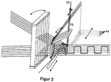
- the Legefadenising 13 for the laying yarn 12 can be brought by a transverse movement in each laying position between the Kettlegegliedern 14. This is followed by the basic movement described above FIG. 1 ,
- the laying thread 12 may be an effect thread, eg wires, bead cords, elastic threads, etc., or else a functional thread, eg an LED thread, conductive thread, etc.
- the laying yarn guide 13 can be moved between the warp-setting members 14 to the new laying position, e.g. by means of a linear motor, a cam gear, etc. This can - depending on the desired effect and function - be done periodically or according to a freely defined pattern.
- the further chain 8 - in the described embodiment Befest Trentsfäden- may alternatively or as an additional effect, a chain of effect threads.
- the warp-laying apparatus 9 can also be displaced in the transverse movement by one or more warp-setting members 14 in order to lay and bind a laying yarn 12 in the warp direction of the band fabric 10. This allows new patterns and effects.
- the Kettlegeglieder 14 are arranged in a fixed, in the present embodiment the same distance next to each other.
- Each Legefaden founded 13, 16 is operated by a separate drive and can be moved independently in the transverse direction. On this loom, the Legefäden 12 and 15 can be crossed and it can be achieved as new effects.
- FIG. 4 A further embodiment of the invention is in FIG. 4 shown.
- a retaining hook is used.
- the retaining hook 17 holds the laying thread in order to reduce the load on the additional warp thread 8 - in the exemplary embodiment of a fastening thread.
- the movement of the retention hook can be done via rotation as well as a linear movement. It can be used on a weave in the retaining hook two or more members 18. Once the laying yarn 12 has been laid, the retaining hook 17 again moves away from the tape fabric 10 to its original position or remains in position until the laying yarn 12 has set.
- FIG. 5 a weaving machine according to an embodiment using three adjacent, parallel Kettlegevoroplastyen 9 is shown.
- the Kettlegevoriquesen correspond to those in the embodiments described above and are for clarity in FIG FIG. 5 not shown again.
- the inventive technique is advantageously used in that several Kettlegevortechnischen 9 - in the illustrated embodiment just three - are arranged side by side parallel to the selvedge at a defined distance.
- several bands are made in parallel next to each other. If the belts are similar, solely to increase the rate of production, the warp knitting devices 9 are driven coupled thereto.
- individual drives are provided so that the Kettlegevortechnischen 9 are driven individually and independently controlled.
Landscapes
- Engineering & Computer Science (AREA)
- Textile Engineering (AREA)
- Looms (AREA)
Description
- Die Erfindung betrifft eine Webmaschine zur Herstellung von Webgut mit einem eingearbeiteten Legefaden.
- Eine Webmaschine der eingangs genannten Art ist aus der
CH 490 541 US 3 796 234 offenbart. - Aus der
WO 2007/071077 A1 ist bekannt, einen Leiterfaden auf verschiedenste Weisen einzuarbeiten, indem die Zuführungsnadel an einer quer zur Kettrichtung ausgerichteten Welle angeordnet ist, die mit einer ersten Antriebsvorrichtung zum Ausführen einer Schwenkbewegung der Welle und weiterhin mit einer zweiten Antriebsvorrichtung zum Verfahren in Achsrichtung verbunden ist. Der Stecher taucht durch das Schwenken in das Webfach ein und aus. Dadurch kann der Stecher über die Breite des Bandes hinweg verfahren werden. - Aus der
JP 2005/015954 A JP 2005/015954 A - Aufgabe der Erfindung ist es, eine Webmaschine anzugeben, die zur Herstellung von Webgut mit einem einarbeiteten Legefaden geeignet ist. Dabei soll die Maschine zum Aufbringen eines Legefadens auf ein Webgut geeignet sein, ohne das Webgut merklich zu verändern.
- Die Aufgabe wird bei der eingangs genannten Webmaschine durch die Maschine nach Anspruch 1 gelöst. Dabei haben die Massnahmen der Erfindung zunächst einmal zur Folge, dass ein Legefaden auch bei einer Querbewegung des Legefadenführers - in Schussrichtung - abgebunden werden kann. Weiterhin ist - und das ist besonders vorteilhaft - durch die Verteilung der Bewegungen, nämlich das Anbinden und die Schusslegung - auf zwei Bewegungen keine Abbindung auf der Warenseite des Bandgewebes sichtbar. Dabei ist die Maschine - im Gegensatz zur Webmaschine der
JP 2005/015954 A JP 2005/015954 A - Sehr vorteilhaft ist auch, dass der Legefaden in jede Legeposition zwischen den Kettlegegliedern auf dem Bandgewebe bewegt und gelegt werden kann.
- Vorteilhafte Ausgestaltungen der Webmaschine sind in den abhängigen Ansprüchen beschrieben.
- Vorteilhaft ist es, wenn auch die Kettlegevorrichtung Querbewegemittel aufweist, mittels derer sie quer zu den Kettfäden bewegbar ist, wenn sie nicht in das Webfach eingetaucht ist.
- Gemäss einer vorteilhaften Ausführung der vorliegenden Erfindung weist die Legevorrichtung zumindest einen weiteren Legefadenführer auf, der in Kettfadenrichtung hinter dem genannten Legefadenführer angeordnet ist und quer zur Kettfadenrichtung bewegbar ist.
- Gemäss einer weiteren Ausführung der vorliegenden Erfindung weist die Vorrichtung zumindest einen Rückhaltehaken auf, der bei angeschlagenem Webblatt den Legefaden halten kann. Dabei wird der Rückhaltehaken so geführt, dass er nach dem Legen des Legefadens vom Bandgewebe weg in eine Ausgangsposition bewegbar ist.
- Die vorstehend genannten Ausgestaltungen beziehen sich zunächst einmal auf Bandwebmaschinen. Auf breiteren Webmaschinen kann die erfindungsgemässe Technik vorteilhaft dadurch eingesetzt werden, dass mehrere Kettlegevorrichtungen parallel zur Webkante nebeneinander in einem definierten Abstand angeordnet sind. Vorzugsweise werden die Kettlegevorrichtungen dabei gekoppelt angetrieben. Für bestimme Anwendungen kann es aber auch vorteilhaft sein, wenn Einzelantriebe vorgesehen sind, so dass die Kettlegevorrichtungen einzeln und unabhängig voneinander gesteuert angetrieben werden.
- Die vorbenannten, sowie die beanspruchten und in den nachfolgenden Ausführungsbeispielen beschriebenen, erfindungsgemäss zu verwendenden Elemente unterliegen in ihrer Grösse, Formgestaltung, Materialverwendung und ihrer technischen Konzeption keinen besonderen Ausnahmebedingungen, so dass die in dem jeweiligen Anwendungsgebiet bekannten Auswahlkriterien uneingeschränkt Anwendung finden können.
- Ausführungsbeispiele der Webmaschine werden nachfolgend anhand der Zeichnungen näher beschrieben, dabei zeigen:
- Figur 1
- eine Webmaschine gemäss eines ersten Ausführungsbeispiels der vorliegenden Erfindung, als schematische Darstellung zur Erläuterung der Grundbewegung;
- Figur 2
- die Webmaschine nach
Figur 1 , als schematische Darstellung zur Erläuterung der Legebewegung des Legefadenführers; - Figur 3
- eine Webmaschine gemäss eines zweiten Ausführungsbeispiels der vorliegenden Erfindung mit mehreren Legefadenführern, als schematische Darstellung;
- Figur 4
- eine Webmaschine gemäss eines dritten Ausführungsbeispiels der vorliegenden Erfindung mit einem Rückhaltehaken, als schematische Darstellung;
- Figur 5
- eine Webmaschine gemäss eines Ausführungsbeispiels mit drei nebeneinander liegenden, parallel arbeitenden Kettlegevorrichtungen.
- Die
Figur 1 zeigt eine Webmaschine gemäss einem ersten Ausführungsbeispiel der vorliegenden Erfindung, als schematische Darstellung zur Erläuterung der Grundbewegung. Die Kettfäden 2 zum Herstellen eines Bandgewebes 10 bilden zum Eintrag eines Schussfadens mittels einer Schusseintragsnadel 7 oder eines Greifers - bei einer Greiferwebmaschine - ein Oberfach 5 und ein Unterfach 4. Ein Webblatt 1 ist in herkömmlicher Weise angeordnet, um die eingetragenen Schussfäden an das bereits erstellte Webgut 10 anzuschlagen. - Die Kettlegevorrichtung 9 taucht durch das Oberfach 5 in das Unterfach 4 ein. Gleichzeitig bewegt sich das Webblatt 1 nach hinten. Die Kettlegevorrichtung 9 kann in Richtung Webblatt 1 wie auch nach unten in das Unterfach 4 bewegt werden. Die Kettlegevorrichtung 9 folgt in der dargestellten Ausführung der Bewegung des Webblattes 1. Die Kettlegevorrichtung kann aber auch abgeschaltet werden bzw. kann je nach Bindung unterschiedlich oft abgetaucht werden.
- Der Schuss der Schusseintragsnadel oder des Greifers 7 kreuzt die Zusatzkettfäden 8, falls sich die Kettlegeglieder im Unterfach befinden. Der Schuss der Schusseintragsnadel 7 oder des Greifers wird im dargestellten Ausführungsbeispiel mittels eines Hilfsfadens abgebunden. Die Kettlegevorrichtung 9 taucht die Kettlegeglieder aus dem Unterfach 4 und dem Oberfach 5 auf und bewegt sich mit dem Webblatt 1 in die Ausgangsposition 11. Danach werden die Zusatzkettfäden 8 - im dargestellten Ausführungsbeispiel Befestigungsfäden - durch das Webblatt 1 angeschlagen. Die Kettlegung muss so angelegt werden, dass sie nie an die Deckschüsse angebunden wird.
- In
Figur 2 ist die zusätzliche Legung mittels eines Legefadenführers erläutert. Der Legefadenführer 13 für den Legefaden 12 kann durch eine Querbewegung in jede Legeposition zwischen den Kettlegegliedern 14 gebracht werden. Darauf folgt die zuvor beschriebene Grundbewegung gemässFigur 1 . Der Legefaden 12 kann ein Effektfaden, z.B. Drähte, Perlenschnüre, elastische Fäden etc. oder auch ein Funktionsfaden, z.B. ein LED-Faden, leitender Faden etc. sein. - Wenn die Kettlegevorrichtung 9 in der Ausgangsposition 11 steht, kann der Legefadenführer 13 zwischen die Kettlegeglieder 14 an die neue Legeposition bewegt werden, z.B. mittels eines Linearmotors, eines Kurvengetriebe etc. Dies kann - je nach gewünschtem Effekt und Funktion - periodisch oder nach einem frei definierten Muster geschehen.
- Mit der Zusatzkette, also den Befestigungsfäden 8 wird der Legefaden 12, speziell auch in Schussrichtung, auf das Bandgewebe 10 abgebunden. Die weitere Kette 8 - im beschriebenen Ausführungsbeispiel Befestigungsfäden- kann alternativ oder als zusätzlicher Effekt auch eine Kette aus Effektfäden sein.
- Die Kettlegevorrichtung 9 kann auch in der Querbewegung um ein oder mehrere Kettlegeglieder 14 verschoben werden, um einen Legefaden 12 in der Kettfadenrichtung des Bandgewebes 10 zu legen und abzubinden. Dies ermöglicht neue Muster und Effekte. Die Kettlegeglieder 14 sind in einem festen, im vorliegenden Ausführungsbeispiel gleichem Abstand nebeneinander angeordnet.
- Gemäss eines weiteren Ausführungsbeispiels der vorliegenden Erfindung, welches in
Figur 3 dargestellt ist, können mehrere Legefadenführer hintereinander aufgereiht werden. - Jeder Legefadenführer 13, 16 wird über einen eigenen Antrieb betrieben und kann unabhängig voneinander in Querrichtung bewegt werden.
Auf dieser Webmaschine können die Legefäden 12 und 15 gekreuzt werden und es können so neue Effekte erzielt werden. - Eine weitere Ausgestaltung der Erfindung ist in
Figur 4 dargestellt. Bei diesem Ausführungsbeispiel kommt ein Rückhaltehaken zum Einsatz. - Der Rückhaltehaken 17 hält den Legefaden, um die Belastung des Zusatzkettfadens 8 - im Ausführungsbeispiel eines Befestigungsfadens - zu verringern. Die Bewegung des Rückhaltehakens kann über Rotation wie auch über eine lineare Bewegung erfolgen. Es können beim Rückhaltehaken zwei oder mehrere Glieder 18 auf einem Webgang eingesetzt werden. Sobald der Legefaden 12 gelegt ist, bewegt sich der Rückhaltehaken 17 wieder weg vom Bandgewebe 10 in seine Ausgangsposition oder bleibt in Position, bis der Legefaden 12 abgebunden ist.
- In
Figur 5 ist eine Webmaschine gemäss eines Ausführungsbeispiels unter Einsatz von drei nebeneinander liegenden, parallel arbeitenden Kettlegevorrichtungen 9 dargestellt. Die Kettlegevorrichtungen entsprechen denen in den vorstehend beschriebenen Ausführungsbeispielen und sind der Übersichtlichkeit halber inFigur 5 nicht nochmals dargestellt. Auf einer solchen, breiteren Webmaschine wird die erfindungsgemässe Technik vorteilhaft dadurch eingesetzt, dass mehrere Kettlegevorrichtungen 9 - im dargestellten Ausführungsbeispiel eben drei - parallel zur Webkante nebeneinander in einem definierten Abstand angeordnet sind. Im dargestellten Ausführungsbeispiel ist dabei angedeutet, nebeneinander mehrere Bänder parallel hergestellt werden. Wenn die Bänder - allein zur Erhöhung der Produktionsrate - gleichartig sind, werden die Kettlegevorrichtungen 9 dazu gekoppelt angetrieben. Für bestimme Anwendungen, z.B. wenn unterschiedlich ausgestaltete Bänder nebeneinander oder wenn unterschiedliche Applikationen auf einem Breitwebgut 10 hergestellt werden sollen, kann es aber auch vorteilhaft sein, wenn Einzelantriebe vorgesehen sind, so dass die Kettlegevorrichtungen 9 einzeln und unabhängig voneinander gesteuert angetrieben werden. -
- 1
- Webblatt
- 2
- Kettfäden eines Bandgewebes
- 3
- Webfach
- 4
- Unterfach
- 5
- Oberfach
- 6
- Abbinde- oder Abhäkelnadel
- 7
- Schusseintragsnadel oder Schusseintragsgreifer
- 8
- Zusatzkettfäden als Befestigungsfäden oder als Effektfäden
- 9
- Kettlegevorrichtung
- 10
- Bandgewebe
- 11
- Ausgangsposition der Kettlegevorrichtung
- 12
- Legefaden
- 13
- Legefadenführer
- 14
- Kettlegeglieder
- 15
- zweiter Legefaden
- 16
- zweiter Legefadenführer
- 17
- Rückhaltehaken
- 18
- Glieder des Rückhaltehakens
Claims (9)
- Webmaschine zum Herstellen von Webgut (10) mit einem eingearbeiteten Legefaden, mit- einer Fachbildevorrichtung zum Bilden eines Webfaches (3) aus Kettfäden (2) mit zumindest einem Oberfach (5) und einem Unterfach (4),- einer Schusseintragsvorrichtung (7) zum Eintragen von Schussfäden,- einem Webblatt (1) zum Anschlagen eingetragener Schussfäden,- einer Legevorrichtung für zumindest einen Legefaden (12),dadurch gekennzeichnet, dassdie Webmaschine weiterhin eine Kettlegevorrichtung (9) mit einer Vielzahl von nebeneinander angeordneten Kettlegegliedern (14) für das Legen von Zusatzkettfäden (8) aufweist,wobei die Kettlegevorrichtung (9) eine Antriebseinrichtung zum Eintauchen der Kettlegeglieder (14) für die Zusatzkettfäden (8) aus einer Ausgangsstellung durch das Oberfach (5) bis zum Unterfach (4) oder durch das Unterfach bis zum Oberfach aufweist, und die Kettlegevorrichtung so positioniert ist, dass die Schusseintragsvorrichtung (7) die Zusatzkettfäden (8) kreuzt, und wobei die Legevorrichtung zumindest einen Legefadenführer (13) aufweist, der in Ausgangsstellung (11) der Kettlegevorrichtung (9) mittels eines Querbewegemittels quer zu den Kettfäden (2) verfahrbar ist.
- Webmaschine nach Anspruch 1, dadurch gekennzeichnet, dass der Legefadenführer (13) mittels des Querbewegemittels in jeder Stellung des Webfaches verfahrbar ist.
- Webmaschine nach Anspruch 1 oder 2, dadurch gekennzeichnet, dass die Kettlegeglieder (14) der Kettlegevorichtung (9) in einem festen, vorzugsweise gleichem Abstand nebeneinander angeordnet sind.
- Webmaschine nach einem der Ansprüche 1 bis 3, dadurch gekennzeichnet, dass die Kettlegevorrichtung (9) weiterhin Querbewegemittel aufweist, mittels derer die Kettlegeglieder (14) quer zu den Kettfäden (2) bewegbar sind, wenn sie nicht in das Webfach (3) eingetaucht sind.
- Webmaschine nach einem der Ansprüche 1 bis 4, dadurch gekennzeichnet, dass die Legevorrichtung zumindest einen weiteren Legefadenführer (16) aufweist, der in Kettfadenrichtung (2) hinter dem genannten Legefadenführer (13) angeordnet ist und quer zur Kettfadenrichtung (2) bewegbar ist.
- Webmaschine nach einem der Ansprüche 1 bis 5, gekennzeichnet durch zumindest einen bewegbaren Rückhaltehaken (17) zum Halten des Legefadens (12) zur Verringerung der Belastung des Zusatzkettfadens (8), wobei der Rückhaltehaken (17) nach dem Legen des Legefadens (12) vom Bandgewebe (10) weg in eine Ausgangsposition bewegbar ist.
- Webmaschine nach einem der Ansprüche 1 bis 6, dadurch gekennzeichnet, dass mehrere Kettlegevorrichtungen (9) parallel zur Webkante nebeneinander in einem definierten Abstand angeordnet sind.
- Webmaschine nach Anspruch 7, dadurch gekennzeichnet, dass die Kettlegevorrichtungen (9) Einheiten gekoppelt angetrieben werden.
- Webmaschine nach Anspruch 7, dadurch gekennzeichnet, dass Einzelantriebe vorgesehen sind, so dass die Kettlegevorrichtungen (9) einzeln und unabhängig voneinander angetrieben werden.
Priority Applications (1)
| Application Number | Priority Date | Filing Date | Title |
|---|---|---|---|
| EP11725060.5A EP2580379B1 (de) | 2010-06-09 | 2011-06-08 | Webmaschine zur herstellung von webgut mit einem eingearbeiteten legefaden |
Applications Claiming Priority (3)
| Application Number | Priority Date | Filing Date | Title |
|---|---|---|---|
| EP10165399A EP2395140A1 (de) | 2010-06-09 | 2010-06-09 | Webmaschine zur Herstellung von Webgut mit einem eingearbeiteten Legefaden |
| PCT/EP2011/059494 WO2011154449A1 (de) | 2010-06-09 | 2011-06-08 | Webmaschine zur herstellung von webgut mit einem eingearbeiteten legefaden |
| EP11725060.5A EP2580379B1 (de) | 2010-06-09 | 2011-06-08 | Webmaschine zur herstellung von webgut mit einem eingearbeiteten legefaden |
Publications (2)
| Publication Number | Publication Date |
|---|---|
| EP2580379A1 EP2580379A1 (de) | 2013-04-17 |
| EP2580379B1 true EP2580379B1 (de) | 2018-11-07 |
Family
ID=42735525
Family Applications (2)
| Application Number | Title | Priority Date | Filing Date |
|---|---|---|---|
| EP10165399A Withdrawn EP2395140A1 (de) | 2010-06-09 | 2010-06-09 | Webmaschine zur Herstellung von Webgut mit einem eingearbeiteten Legefaden |
| EP11725060.5A Active EP2580379B1 (de) | 2010-06-09 | 2011-06-08 | Webmaschine zur herstellung von webgut mit einem eingearbeiteten legefaden |
Family Applications Before (1)
| Application Number | Title | Priority Date | Filing Date |
|---|---|---|---|
| EP10165399A Withdrawn EP2395140A1 (de) | 2010-06-09 | 2010-06-09 | Webmaschine zur Herstellung von Webgut mit einem eingearbeiteten Legefaden |
Country Status (10)
| Country | Link |
|---|---|
| US (1) | US20130118633A1 (de) |
| EP (2) | EP2395140A1 (de) |
| JP (1) | JP5822918B2 (de) |
| KR (1) | KR101894602B1 (de) |
| CN (1) | CN103097597B (de) |
| BR (1) | BR112012031390B1 (de) |
| CA (1) | CA2801544A1 (de) |
| ES (1) | ES2709573T3 (de) |
| TR (1) | TR201900871T4 (de) |
| WO (1) | WO2011154449A1 (de) |
Families Citing this family (14)
| Publication number | Priority date | Publication date | Assignee | Title |
|---|---|---|---|---|
| DE102012200835B3 (de) * | 2012-01-20 | 2013-03-14 | Lindauer Dornier Gesellschaft Mit Beschränkter Haftung | Webmaschine mit einer Vorrichtung zur Bildung von Zusatzschusseffekten |
| CN103469449A (zh) * | 2013-04-03 | 2013-12-25 | 南通纺织职业技术学院 | 带绗缝功能的纺织小样机 |
| FR3022266B1 (fr) * | 2014-06-16 | 2016-05-27 | Tresse Ind | Tissu pour blindage electromagnetique. |
| CN111534899B (zh) * | 2014-12-22 | 2021-12-07 | 苹果公司 | 织造织物中的导电信号路径 |
| CN104727001B (zh) * | 2015-04-20 | 2016-09-07 | 江苏工程职业技术学院 | 一种缂丝半自动小样机装置 |
| EP3141642A1 (de) | 2015-09-10 | 2017-03-15 | Textilma Ag | Webmaschine zur herstellung von webgut mit eingearbeiteten wirk- oder legefäden |
| EP3257983A1 (de) | 2016-06-15 | 2017-12-20 | Textilma Ag | Nadelbandwebmaschine und entsprechendes webverfahren |
| CN106367865B (zh) * | 2016-12-02 | 2018-02-02 | 江苏工程职业技术学院 | 一种涤纶纤维/粘胶纤维双层垫纱面料织物的生产工艺 |
| US11913143B2 (en) | 2019-03-08 | 2024-02-27 | Apple Inc. | Fabric with electrical components |
| EP3722470A1 (de) * | 2019-04-10 | 2020-10-14 | Textilma AG | Verfahren zum mustergesteuerten ausbilden des anbindungspunktes eines effektfadens im gewebe |
| EP3741892B1 (de) | 2019-05-19 | 2021-08-11 | Textilma AG | Webmaschine zur herstellung von webgut mit eingearbeiteten effektfäden |
| US12583193B2 (en) * | 2021-03-26 | 2026-03-24 | Mitsui Chemicals, Inc. | Production apparatus for producing a fiber-reinforced resin and a production method for producing a fiber-reinforced resin |
| EP4617414A1 (de) | 2024-03-13 | 2025-09-17 | Jakob Müller AG Frick | Textilstruktur und herstellungsverfahren dafür |
| CN119736748B (zh) * | 2025-03-03 | 2025-08-15 | 泉州市和景荣纺织品有限公司 | 一种浮花织带织造设备及织造工艺 |
Family Cites Families (30)
| Publication number | Priority date | Publication date | Assignee | Title |
|---|---|---|---|---|
| NL6712677A (de) * | 1967-09-15 | 1969-03-18 | ||
| US3586063A (en) * | 1968-11-12 | 1971-06-22 | Monsanto Co | Fabric and method for weaving |
| FR1598697A (de) * | 1968-12-24 | 1970-07-06 | ||
| CH490541A (de) | 1969-05-05 | 1970-05-15 | Mueller Jakob | Verfahren und Vorrichtung zur Anbringung mindestens eines Effektfadens und/oder mindestens eines Befestigungsfadens für Gegenstände an Geweben, insbesondere Bandgeweben, während des Webvorganges |
| GB1311802A (en) * | 1970-01-20 | 1973-03-28 | French & Sons Thomas | Curtain heading tape |
| US3665733A (en) * | 1970-07-16 | 1972-05-30 | Union Carbide Corp | Apparatus and method for warp knitting a simulated woven fabric |
| US3682205A (en) * | 1970-07-28 | 1972-08-08 | Textron Inc | Needle loom |
| US3796234A (en) | 1972-05-15 | 1974-03-12 | J Muller | Method and apparatus for anchoring a floating yarn portion in a woven fabric |
| CH594084A5 (de) * | 1974-10-29 | 1977-12-30 | Patax Trust Reg | |
| JPS5576137A (en) * | 1978-11-27 | 1980-06-09 | Hiyougoken | Patter apparatus for lappet loom |
| CH639710A5 (de) * | 1979-11-08 | 1983-11-30 | Textilma Ag | Verfahren zur herstellung eines gewebes, webmaschine zur durchfuehrung des verfahrens und nach dem verfahren hergestelltes gewebe. |
| US4520636A (en) * | 1979-11-28 | 1985-06-04 | Burlington Industries, Inc. | Woven-like warp knit fabric with tension control for top effect yarn |
| US4429722A (en) * | 1981-05-18 | 1984-02-07 | Quaker Fabric Corp. | Method and apparatus for weaving fabrics of novel construction |
| DE59108995D1 (de) * | 1990-05-11 | 1998-07-02 | Rueti Ag Maschf | Reihenfachwebmaschine |
| US5188154A (en) * | 1991-05-21 | 1993-02-23 | Sulzer Brothers Limited | Weaving rotor comb fin design for series-shed loom |
| DE59207254D1 (de) * | 1992-03-26 | 1996-10-31 | Rueti Ag Maschf | Luftleistenlegervorrichtung für Webmaschinen |
| DE59303756D1 (de) * | 1993-02-26 | 1996-10-17 | Rueti Ag Maschf | Einlegevorrichtung für eine Reihenfachwebmaschine |
| DE19538642A1 (de) * | 1995-10-17 | 1997-04-24 | Kd Ingenieurtechnik Gmbh | Kühl- und Montageanordnung für eine Reihe von Halbleiter-Bauelementen |
| US5924459A (en) * | 1997-06-02 | 1999-07-20 | Evans; Rowland G. | Air jet machine and diagonal Z loop fabric pattern for three-dimensional fabric |
| TW512190B (en) * | 2000-04-11 | 2002-12-01 | Textilma Ag | Narrow fabric needle loom for producing a strip-shaped tissue and corresponding strip-shaped tissue |
| JP3928178B2 (ja) * | 2002-08-07 | 2007-06-13 | 株式会社川島織物セルコン | 弾性布帛と弾性面材 |
| KR100648607B1 (ko) * | 2002-09-03 | 2006-11-23 | 린 첸-후이 | 직기의 다색 위사 선택 방법 |
| JP2005015954A (ja) * | 2003-06-26 | 2005-01-20 | Kawashima Textile Manuf Ltd | 柄糸経緯織込織機と織物 |
| FR2889208B1 (fr) * | 2005-08-01 | 2007-10-19 | Jacques Abramo | Dispositif de tricotage pour la confection d'un textile double face epais |
| CA2631628A1 (en) | 2005-12-23 | 2007-06-28 | Textilma Ag | Ribbon needle loom for manufacturing a strip, in particular a label strip, having a woven-in conductive thread, in particular antenna thread |
| ITMI20060252A1 (it) * | 2006-02-13 | 2007-08-14 | Algesta S R L | Macchina per la tessitura e la contemporanea ricamature di articoli di vestiario in particolare copricapo ricamati |
| DE102006013886B3 (de) * | 2006-03-25 | 2007-11-29 | Halbach Seidenbänder Vertrieb GmbH | Verfahren und Vorrichtung zur Herstellung eines gewebten Bandes |
| DE102008036347A1 (de) * | 2008-08-05 | 2010-02-11 | Eschke, Helga | Verfahren zum Einbringen sich partiell in der Gewebebreite zusätzlich erstreckender Schussfäden während des maschinellen Webprozesses |
| CN201459338U (zh) * | 2009-04-17 | 2010-05-12 | 南通纺织职业技术学院 | 一种织物小样织机 |
| NL1036870C2 (nl) * | 2009-04-17 | 2010-10-19 | Ten Cate Itex B V | Inrichting voor het door middel van weven vervaardigen van een vezelmat. |
-
2010
- 2010-06-09 EP EP10165399A patent/EP2395140A1/de not_active Withdrawn
-
2011
- 2011-06-08 KR KR1020127032801A patent/KR101894602B1/ko active Active
- 2011-06-08 US US13/261,534 patent/US20130118633A1/en not_active Abandoned
- 2011-06-08 ES ES11725060T patent/ES2709573T3/es active Active
- 2011-06-08 BR BR112012031390-8A patent/BR112012031390B1/pt active IP Right Grant
- 2011-06-08 TR TR2019/00871T patent/TR201900871T4/tr unknown
- 2011-06-08 CN CN201180028748.7A patent/CN103097597B/zh not_active Expired - Fee Related
- 2011-06-08 EP EP11725060.5A patent/EP2580379B1/de active Active
- 2011-06-08 JP JP2013513679A patent/JP5822918B2/ja active Active
- 2011-06-08 CA CA2801544A patent/CA2801544A1/en not_active Abandoned
- 2011-06-08 WO PCT/EP2011/059494 patent/WO2011154449A1/de not_active Ceased
Non-Patent Citations (1)
| Title |
|---|
| None * |
Also Published As
| Publication number | Publication date |
|---|---|
| JP5822918B2 (ja) | 2015-11-25 |
| TR201900871T4 (tr) | 2019-02-21 |
| EP2395140A1 (de) | 2011-12-14 |
| CN103097597B (zh) | 2014-05-21 |
| WO2011154449A1 (de) | 2011-12-15 |
| KR20130081661A (ko) | 2013-07-17 |
| HK1180019A1 (en) | 2013-10-11 |
| US20130118633A1 (en) | 2013-05-16 |
| CA2801544A1 (en) | 2011-12-15 |
| BR112012031390A2 (pt) | 2016-11-16 |
| KR101894602B1 (ko) | 2018-09-04 |
| BR112012031390A8 (pt) | 2017-12-12 |
| BR112012031390B1 (pt) | 2020-05-12 |
| JP2013531745A (ja) | 2013-08-08 |
| CN103097597A (zh) | 2013-05-08 |
| EP2580379A1 (de) | 2013-04-17 |
| ES2709573T3 (es) | 2019-04-16 |
Similar Documents
| Publication | Publication Date | Title |
|---|---|---|
| WO2011154449A1 (de) | Webmaschine zur herstellung von webgut mit einem eingearbeiteten legefaden | |
| EP2531639B1 (de) | Webmaschine zur herstellung von geweben mit zusatzschusseffekten | |
| EP2004889B1 (de) | Gurtband, verfahren und nadel-bandwebmaschine zur herstellung desselben | |
| EP3347512B1 (de) | Webmaschine zur herstellung von webgut mit eingearbeiteten wirk- oder legefäden | |
| DE102012200835B3 (de) | Webmaschine mit einer Vorrichtung zur Bildung von Zusatzschusseffekten | |
| DE69220043T2 (de) | Multiaxialweben | |
| DE2017446A1 (de) | Verfahren und Vorrichtung zur Anbringung mindestens eines Effektfadens und/oder mindestens eines Befestigungsfadens für Gegenstände an Geweben, insbesondere Bandgeweben, während des Webvorganges | |
| DE10021341A1 (de) | Verfahren und Vorrichtung zur Bildung von, insbesondere mehrschichtigen Schußfäden-Verlegungen multiaxial orientierter Fadengelege und Fadenleger hierfür, sowie mehrschichtiges Schußfädengelege | |
| CH598382A5 (en) | Needle loom for narrow goods | |
| EP2683862A2 (de) | Schaftwebmaschine und entsprechendes webverfahren | |
| EP3741892B1 (de) | Webmaschine zur herstellung von webgut mit eingearbeiteten effektfäden | |
| DE2051572B2 (de) | Webverfahren zur herstellung vielfarbiger baender und zugehoeriger schuetzenjacquardbandwebstuhl | |
| EP1607501B1 (de) | Verfahren und Vorrichtung zur Fachbildung jacquardgemusterter Polkettfäden auf einer Doppelflorwebmaschine | |
| EP0998601A1 (de) | Kettenwirkmaschine, insbesondere häkelgalonmaschine | |
| DE2305674C2 (de) | Ware, bestehend aus einem Kettengewirk und zwischen den Maschenstäbchen eingelegten Längsfäden und Vorrichtung zu ihrer Herstellung | |
| DE102005013214A1 (de) | Vorrichtung sowie Verfahren zur Herstellung einer Kettenwirkware | |
| DE2104443A1 (de) | Verfahren und Vorrichtung zum Her stellen von Textilstoffen | |
| DE102023205630B3 (de) | Verfahren zur bildung einer schlaufenförmigen webkante an einer greiferwebmaschine und greiferwebmaschine | |
| DE1814225B2 (de) | Gewebe und Webeinrichtung zu seiner Erzeugung | |
| DE1760501C3 (de) | Schussgarn Mischeinrichtung für eine schützenlose Webmaschine | |
| DE3421050C2 (de) | ||
| DE19641338C2 (de) | Verfahren und Vorrichtungen zur Schichtkörperherstellung | |
| DE19602552C2 (de) | Verfahren und Vorrichtung zum Herstellen eines Bandgewebes | |
| DE2204956C3 (de) | Nadelwebmaschine | |
| CH532669A (de) | Verfahren und Schützen-Jacquardbandwebstuhl zur Herstellung mehrfarbiger Bänder sowie nach dem Verfahren hergestelltes mehrfarbiges Band |
Legal Events
| Date | Code | Title | Description |
|---|---|---|---|
| PUAI | Public reference made under article 153(3) epc to a published international application that has entered the european phase |
Free format text: ORIGINAL CODE: 0009012 |
|
| 17P | Request for examination filed |
Effective date: 20121024 |
|
| AK | Designated contracting states |
Kind code of ref document: A1 Designated state(s): AL AT BE BG CH CY CZ DE DK EE ES FI FR GB GR HR HU IE IS IT LI LT LU LV MC MK MT NL NO PL PT RO RS SE SI SK SM TR |
|
| DAX | Request for extension of the european patent (deleted) | ||
| GRAP | Despatch of communication of intention to grant a patent |
Free format text: ORIGINAL CODE: EPIDOSNIGR1 |
|
| STAA | Information on the status of an ep patent application or granted ep patent |
Free format text: STATUS: GRANT OF PATENT IS INTENDED |
|
| INTG | Intention to grant announced |
Effective date: 20180810 |
|
| GRAS | Grant fee paid |
Free format text: ORIGINAL CODE: EPIDOSNIGR3 |
|
| GRAA | (expected) grant |
Free format text: ORIGINAL CODE: 0009210 |
|
| STAA | Information on the status of an ep patent application or granted ep patent |
Free format text: STATUS: THE PATENT HAS BEEN GRANTED |
|
| AK | Designated contracting states |
Kind code of ref document: B1 Designated state(s): AL AT BE BG CH CY CZ DE DK EE ES FI FR GB GR HR HU IE IS IT LI LT LU LV MC MK MT NL NO PL PT RO RS SE SI SK SM TR |
|
| REG | Reference to a national code |
Ref country code: GB Ref legal event code: FG4D Free format text: NOT ENGLISH |
|
| REG | Reference to a national code |
Ref country code: AT Ref legal event code: REF Ref document number: 1062170 Country of ref document: AT Kind code of ref document: T Effective date: 20181115 Ref country code: CH Ref legal event code: EP |
|
| REG | Reference to a national code |
Ref country code: IE Ref legal event code: FG4D Free format text: LANGUAGE OF EP DOCUMENT: GERMAN |
|
| REG | Reference to a national code |
Ref country code: DE Ref legal event code: R096 Ref document number: 502011014967 Country of ref document: DE |
|
| REG | Reference to a national code |
Ref country code: CH Ref legal event code: NV Representative=s name: SCHMAUDER AND PARTNER AG PATENT- UND MARKENANW, CH |
|
| REG | Reference to a national code |
Ref country code: NL Ref legal event code: MP Effective date: 20181107 |
|
| REG | Reference to a national code |
Ref country code: LT Ref legal event code: MG4D |
|
| REG | Reference to a national code |
Ref country code: ES Ref legal event code: FG2A Ref document number: 2709573 Country of ref document: ES Kind code of ref document: T3 Effective date: 20190416 |
|
| PG25 | Lapsed in a contracting state [announced via postgrant information from national office to epo] |
Ref country code: LV Free format text: LAPSE BECAUSE OF FAILURE TO SUBMIT A TRANSLATION OF THE DESCRIPTION OR TO PAY THE FEE WITHIN THE PRESCRIBED TIME-LIMIT Effective date: 20181107 Ref country code: BG Free format text: LAPSE BECAUSE OF FAILURE TO SUBMIT A TRANSLATION OF THE DESCRIPTION OR TO PAY THE FEE WITHIN THE PRESCRIBED TIME-LIMIT Effective date: 20190207 Ref country code: FI Free format text: LAPSE BECAUSE OF FAILURE TO SUBMIT A TRANSLATION OF THE DESCRIPTION OR TO PAY THE FEE WITHIN THE PRESCRIBED TIME-LIMIT Effective date: 20181107 Ref country code: NO Free format text: LAPSE BECAUSE OF FAILURE TO SUBMIT A TRANSLATION OF THE DESCRIPTION OR TO PAY THE FEE WITHIN THE PRESCRIBED TIME-LIMIT Effective date: 20190207 Ref country code: IS Free format text: LAPSE BECAUSE OF FAILURE TO SUBMIT A TRANSLATION OF THE DESCRIPTION OR TO PAY THE FEE WITHIN THE PRESCRIBED TIME-LIMIT Effective date: 20190307 Ref country code: LT Free format text: LAPSE BECAUSE OF FAILURE TO SUBMIT A TRANSLATION OF THE DESCRIPTION OR TO PAY THE FEE WITHIN THE PRESCRIBED TIME-LIMIT Effective date: 20181107 Ref country code: HR Free format text: LAPSE BECAUSE OF FAILURE TO SUBMIT A TRANSLATION OF THE DESCRIPTION OR TO PAY THE FEE WITHIN THE PRESCRIBED TIME-LIMIT Effective date: 20181107 |
|
| PG25 | Lapsed in a contracting state [announced via postgrant information from national office to epo] |
Ref country code: GR Free format text: LAPSE BECAUSE OF FAILURE TO SUBMIT A TRANSLATION OF THE DESCRIPTION OR TO PAY THE FEE WITHIN THE PRESCRIBED TIME-LIMIT Effective date: 20190208 Ref country code: NL Free format text: LAPSE BECAUSE OF FAILURE TO SUBMIT A TRANSLATION OF THE DESCRIPTION OR TO PAY THE FEE WITHIN THE PRESCRIBED TIME-LIMIT Effective date: 20181107 Ref country code: PT Free format text: LAPSE BECAUSE OF FAILURE TO SUBMIT A TRANSLATION OF THE DESCRIPTION OR TO PAY THE FEE WITHIN THE PRESCRIBED TIME-LIMIT Effective date: 20190307 Ref country code: AL Free format text: LAPSE BECAUSE OF FAILURE TO SUBMIT A TRANSLATION OF THE DESCRIPTION OR TO PAY THE FEE WITHIN THE PRESCRIBED TIME-LIMIT Effective date: 20181107 Ref country code: SE Free format text: LAPSE BECAUSE OF FAILURE TO SUBMIT A TRANSLATION OF THE DESCRIPTION OR TO PAY THE FEE WITHIN THE PRESCRIBED TIME-LIMIT Effective date: 20181107 Ref country code: RS Free format text: LAPSE BECAUSE OF FAILURE TO SUBMIT A TRANSLATION OF THE DESCRIPTION OR TO PAY THE FEE WITHIN THE PRESCRIBED TIME-LIMIT Effective date: 20181107 |
|
| PG25 | Lapsed in a contracting state [announced via postgrant information from national office to epo] |
Ref country code: CZ Free format text: LAPSE BECAUSE OF FAILURE TO SUBMIT A TRANSLATION OF THE DESCRIPTION OR TO PAY THE FEE WITHIN THE PRESCRIBED TIME-LIMIT Effective date: 20181107 Ref country code: PL Free format text: LAPSE BECAUSE OF FAILURE TO SUBMIT A TRANSLATION OF THE DESCRIPTION OR TO PAY THE FEE WITHIN THE PRESCRIBED TIME-LIMIT Effective date: 20181107 Ref country code: DK Free format text: LAPSE BECAUSE OF FAILURE TO SUBMIT A TRANSLATION OF THE DESCRIPTION OR TO PAY THE FEE WITHIN THE PRESCRIBED TIME-LIMIT Effective date: 20181107 |
|
| REG | Reference to a national code |
Ref country code: DE Ref legal event code: R097 Ref document number: 502011014967 Country of ref document: DE |
|
| PG25 | Lapsed in a contracting state [announced via postgrant information from national office to epo] |
Ref country code: SK Free format text: LAPSE BECAUSE OF FAILURE TO SUBMIT A TRANSLATION OF THE DESCRIPTION OR TO PAY THE FEE WITHIN THE PRESCRIBED TIME-LIMIT Effective date: 20181107 Ref country code: SM Free format text: LAPSE BECAUSE OF FAILURE TO SUBMIT A TRANSLATION OF THE DESCRIPTION OR TO PAY THE FEE WITHIN THE PRESCRIBED TIME-LIMIT Effective date: 20181107 Ref country code: EE Free format text: LAPSE BECAUSE OF FAILURE TO SUBMIT A TRANSLATION OF THE DESCRIPTION OR TO PAY THE FEE WITHIN THE PRESCRIBED TIME-LIMIT Effective date: 20181107 Ref country code: RO Free format text: LAPSE BECAUSE OF FAILURE TO SUBMIT A TRANSLATION OF THE DESCRIPTION OR TO PAY THE FEE WITHIN THE PRESCRIBED TIME-LIMIT Effective date: 20181107 |
|
| PLBE | No opposition filed within time limit |
Free format text: ORIGINAL CODE: 0009261 |
|
| STAA | Information on the status of an ep patent application or granted ep patent |
Free format text: STATUS: NO OPPOSITION FILED WITHIN TIME LIMIT |
|
| 26N | No opposition filed |
Effective date: 20190808 |
|
| PG25 | Lapsed in a contracting state [announced via postgrant information from national office to epo] |
Ref country code: SI Free format text: LAPSE BECAUSE OF FAILURE TO SUBMIT A TRANSLATION OF THE DESCRIPTION OR TO PAY THE FEE WITHIN THE PRESCRIBED TIME-LIMIT Effective date: 20181107 |
|
| PG25 | Lapsed in a contracting state [announced via postgrant information from national office to epo] |
Ref country code: MC Free format text: LAPSE BECAUSE OF FAILURE TO SUBMIT A TRANSLATION OF THE DESCRIPTION OR TO PAY THE FEE WITHIN THE PRESCRIBED TIME-LIMIT Effective date: 20181107 |
|
| PG25 | Lapsed in a contracting state [announced via postgrant information from national office to epo] |
Ref country code: IE Free format text: LAPSE BECAUSE OF NON-PAYMENT OF DUE FEES Effective date: 20190608 |
|
| PG25 | Lapsed in a contracting state [announced via postgrant information from national office to epo] |
Ref country code: LU Free format text: LAPSE BECAUSE OF NON-PAYMENT OF DUE FEES Effective date: 20190608 |
|
| REG | Reference to a national code |
Ref country code: AT Ref legal event code: MM01 Ref document number: 1062170 Country of ref document: AT Kind code of ref document: T Effective date: 20190608 |
|
| PG25 | Lapsed in a contracting state [announced via postgrant information from national office to epo] |
Ref country code: AT Free format text: LAPSE BECAUSE OF NON-PAYMENT OF DUE FEES Effective date: 20190608 |
|
| REG | Reference to a national code |
Ref country code: DE Ref legal event code: R119 Ref document number: 502011014967 Country of ref document: DE |
|
| REG | Reference to a national code |
Ref country code: CH Ref legal event code: PL |
|
| GBPC | Gb: european patent ceased through non-payment of renewal fee |
Effective date: 20200608 |
|
| REG | Reference to a national code |
Ref country code: CH Ref legal event code: AECN Free format text: DAS PATENT WURDE AUFGRUND DES WEITERBEHANDLUNGSANTRAGS VOM 01.04.2021 REAKTIVIERT. |
|
| REG | Reference to a national code |
Ref country code: BE Ref legal event code: MM Effective date: 20200630 |
|
| PG25 | Lapsed in a contracting state [announced via postgrant information from national office to epo] |
Ref country code: GB Free format text: LAPSE BECAUSE OF NON-PAYMENT OF DUE FEES Effective date: 20200608 Ref country code: FR Free format text: LAPSE BECAUSE OF NON-PAYMENT OF DUE FEES Effective date: 20200630 Ref country code: LI Free format text: LAPSE BECAUSE OF NON-PAYMENT OF DUE FEES Effective date: 20200630 Ref country code: CH Free format text: LAPSE BECAUSE OF NON-PAYMENT OF DUE FEES Effective date: 20200630 |
|
| PG25 | Lapsed in a contracting state [announced via postgrant information from national office to epo] |
Ref country code: DE Free format text: LAPSE BECAUSE OF NON-PAYMENT OF DUE FEES Effective date: 20210101 Ref country code: CY Free format text: LAPSE BECAUSE OF FAILURE TO SUBMIT A TRANSLATION OF THE DESCRIPTION OR TO PAY THE FEE WITHIN THE PRESCRIBED TIME-LIMIT Effective date: 20181107 Ref country code: BE Free format text: LAPSE BECAUSE OF NON-PAYMENT OF DUE FEES Effective date: 20200630 |
|
| REG | Reference to a national code |
Ref country code: DE Ref legal event code: R073 Ref document number: 502011014967 Country of ref document: DE |
|
| PG25 | Lapsed in a contracting state [announced via postgrant information from national office to epo] |
Ref country code: MT Free format text: LAPSE BECAUSE OF FAILURE TO SUBMIT A TRANSLATION OF THE DESCRIPTION OR TO PAY THE FEE WITHIN THE PRESCRIBED TIME-LIMIT Effective date: 20181107 Ref country code: HU Free format text: LAPSE BECAUSE OF FAILURE TO SUBMIT A TRANSLATION OF THE DESCRIPTION OR TO PAY THE FEE WITHIN THE PRESCRIBED TIME-LIMIT; INVALID AB INITIO Effective date: 20110608 |
|
| REG | Reference to a national code |
Ref country code: GB Ref legal event code: S28 Free format text: APPLICATION FILED |
|
| REG | Reference to a national code |
Ref country code: DE Ref legal event code: R082 Ref document number: 502011014967 Country of ref document: DE Representative=s name: DENNEMEYER & ASSOCIATES RECHTSANWALTSGESELLSCH, DE Ref country code: DE Ref legal event code: R082 Ref document number: 502011014967 Country of ref document: DE Representative=s name: DENNEMEYER & ASSOCIATES S.A., LU |
|
| PG25 | Lapsed in a contracting state [announced via postgrant information from national office to epo] |
Ref country code: LI Free format text: LAPSE BECAUSE OF NON-PAYMENT OF DUE FEES Effective date: 20200630 Ref country code: CH Free format text: LAPSE BECAUSE OF NON-PAYMENT OF DUE FEES Effective date: 20200630 |
|
| PGRI | Patent reinstated in contracting state [announced from national office to epo] |
Ref country code: LI Effective date: 20210406 Ref country code: CH Effective date: 20210406 |
|
| REG | Reference to a national code |
Ref country code: DE Ref legal event code: R074 Ref document number: 502011014967 Country of ref document: DE |
|
| REG | Reference to a national code |
Ref country code: GB Ref legal event code: S28 Free format text: RESTORATION ALLOWED Effective date: 20210906 |
|
| REG | Reference to a national code |
Ref country code: BE Ref legal event code: NE Effective date: 20210720 |
|
| PG25 | Lapsed in a contracting state [announced via postgrant information from national office to epo] |
Ref country code: FR Free format text: LAPSE BECAUSE OF NON-PAYMENT OF DUE FEES Effective date: 20200630 Ref country code: IT Free format text: LAPSE BECAUSE OF NON-PAYMENT OF DUE FEES Effective date: 20200608 |
|
| PGRI | Patent reinstated in contracting state [announced from national office to epo] |
Ref country code: FR Effective date: 20210907 |
|
| PG25 | Lapsed in a contracting state [announced via postgrant information from national office to epo] |
Ref country code: DE Free format text: LAPSE BECAUSE OF NON-PAYMENT OF DUE FEES Effective date: 20210101 |
|
| PGRI | Patent reinstated in contracting state [announced from national office to epo] |
Ref country code: DE Effective date: 20210904 |
|
| REG | Reference to a national code |
Ref country code: BE Ref legal event code: NF Effective date: 20211118 |
|
| PG25 | Lapsed in a contracting state [announced via postgrant information from national office to epo] |
Ref country code: IT Free format text: LAPSE BECAUSE OF NON-PAYMENT OF DUE FEES Effective date: 20200608 |
|
| PGRI | Patent reinstated in contracting state [announced from national office to epo] |
Ref country code: IT Effective date: 20210720 |
|
| PG25 | Lapsed in a contracting state [announced via postgrant information from national office to epo] |
Ref country code: BE Free format text: LAPSE BECAUSE OF NON-PAYMENT OF DUE FEES Effective date: 20200630 |
|
| PGRI | Patent reinstated in contracting state [announced from national office to epo] |
Ref country code: BE Effective date: 20211118 |
|
| PG25 | Lapsed in a contracting state [announced via postgrant information from national office to epo] |
Ref country code: MK Free format text: LAPSE BECAUSE OF FAILURE TO SUBMIT A TRANSLATION OF THE DESCRIPTION OR TO PAY THE FEE WITHIN THE PRESCRIBED TIME-LIMIT Effective date: 20181107 |
|
| REG | Reference to a national code |
Ref country code: DE Ref legal event code: R082 Ref document number: 502011014967 Country of ref document: DE Representative=s name: DENNEMEYER & ASSOCIATES RECHTSANWALTSGESELLSCH, DE |
|
| PGFP | Annual fee paid to national office [announced via postgrant information from national office to epo] |
Ref country code: DE Payment date: 20250618 Year of fee payment: 15 |
|
| PGFP | Annual fee paid to national office [announced via postgrant information from national office to epo] |
Ref country code: GB Payment date: 20250618 Year of fee payment: 15 |
|
| PGFP | Annual fee paid to national office [announced via postgrant information from national office to epo] |
Ref country code: BE Payment date: 20250618 Year of fee payment: 15 |
|
| PGFP | Annual fee paid to national office [announced via postgrant information from national office to epo] |
Ref country code: FR Payment date: 20250624 Year of fee payment: 15 |
|
| PGFP | Annual fee paid to national office [announced via postgrant information from national office to epo] |
Ref country code: TR Payment date: 20250602 Year of fee payment: 15 |
|
| PGFP | Annual fee paid to national office [announced via postgrant information from national office to epo] |
Ref country code: ES Payment date: 20250728 Year of fee payment: 15 |
|
| PGFP | Annual fee paid to national office [announced via postgrant information from national office to epo] |
Ref country code: IT Payment date: 20250624 Year of fee payment: 15 |
|
| PGFP | Annual fee paid to national office [announced via postgrant information from national office to epo] |
Ref country code: CH Payment date: 20250701 Year of fee payment: 15 |