EP2562771A1 - Noyau à poudre de fer et procédé de fabrication de celui-ci - Google Patents
Noyau à poudre de fer et procédé de fabrication de celui-ci Download PDFInfo
- Publication number
- EP2562771A1 EP2562771A1 EP11783516A EP11783516A EP2562771A1 EP 2562771 A1 EP2562771 A1 EP 2562771A1 EP 11783516 A EP11783516 A EP 11783516A EP 11783516 A EP11783516 A EP 11783516A EP 2562771 A1 EP2562771 A1 EP 2562771A1
- Authority
- EP
- European Patent Office
- Prior art keywords
- heat
- soft magnetic
- magnetic particles
- dust core
- treated compact
- Prior art date
- Legal status (The legal status is an assumption and is not a legal conclusion. Google has not performed a legal analysis and makes no representation as to the accuracy of the status listed.)
- Granted
Links
- 239000000428 dust Substances 0.000 title claims abstract description 110
- 238000004519 manufacturing process Methods 0.000 title claims abstract description 37
- 238000009413 insulation Methods 0.000 claims abstract description 175
- 239000006249 magnetic particle Substances 0.000 claims abstract description 150
- 238000000227 grinding Methods 0.000 claims abstract description 144
- 238000000576 coating method Methods 0.000 claims abstract description 102
- 239000011248 coating agent Substances 0.000 claims abstract description 100
- 239000012530 fluid Substances 0.000 claims abstract description 80
- 238000003754 machining Methods 0.000 claims abstract description 50
- 238000000034 method Methods 0.000 claims abstract description 42
- 238000010438 heat treatment Methods 0.000 claims abstract description 15
- 238000002360 preparation method Methods 0.000 claims abstract description 6
- 239000000470 constituent Substances 0.000 claims description 23
- 230000002093 peripheral effect Effects 0.000 claims description 22
- XLYOFNOQVPJJNP-UHFFFAOYSA-M hydroxide Chemical compound [OH-] XLYOFNOQVPJJNP-UHFFFAOYSA-M 0.000 claims description 21
- 238000005520 cutting process Methods 0.000 claims description 11
- 230000008569 process Effects 0.000 claims description 9
- 238000005498 polishing Methods 0.000 claims description 6
- 229910052749 magnesium Inorganic materials 0.000 claims description 4
- 229910052782 aluminium Inorganic materials 0.000 claims description 3
- 229910052796 boron Inorganic materials 0.000 claims description 3
- 229910052791 calcium Inorganic materials 0.000 claims description 3
- 229910052804 chromium Inorganic materials 0.000 claims description 3
- 229910052698 phosphorus Inorganic materials 0.000 claims description 3
- 229910052710 silicon Inorganic materials 0.000 claims description 3
- 229910052719 titanium Inorganic materials 0.000 claims description 3
- 229910052726 zirconium Inorganic materials 0.000 claims description 3
- XEEYBQQBJWHFJM-UHFFFAOYSA-N Iron Chemical compound [Fe] XEEYBQQBJWHFJM-UHFFFAOYSA-N 0.000 description 57
- 238000005868 electrolysis reaction Methods 0.000 description 25
- 229910052742 iron Inorganic materials 0.000 description 25
- 239000010408 film Substances 0.000 description 24
- 239000002245 particle Substances 0.000 description 21
- 230000000052 comparative effect Effects 0.000 description 16
- 239000000463 material Substances 0.000 description 14
- 229910019142 PO4 Inorganic materials 0.000 description 11
- NBIIXXVUZAFLBC-UHFFFAOYSA-K phosphate Chemical compound [O-]P([O-])([O-])=O NBIIXXVUZAFLBC-UHFFFAOYSA-K 0.000 description 11
- 239000010452 phosphate Substances 0.000 description 11
- 239000006061 abrasive grain Substances 0.000 description 10
- 229920006268 silicone film Polymers 0.000 description 10
- 238000005259 measurement Methods 0.000 description 9
- CPLXHLVBOLITMK-UHFFFAOYSA-N Magnesium oxide Chemical compound [Mg]=O CPLXHLVBOLITMK-UHFFFAOYSA-N 0.000 description 8
- 238000010586 diagram Methods 0.000 description 8
- 229910045601 alloy Inorganic materials 0.000 description 7
- 239000000956 alloy Substances 0.000 description 7
- 239000002131 composite material Substances 0.000 description 7
- 229910052751 metal Inorganic materials 0.000 description 7
- 239000002184 metal Substances 0.000 description 7
- 238000004458 analytical method Methods 0.000 description 6
- 229910000398 iron phosphate Inorganic materials 0.000 description 6
- WBJZTOZJJYAKHQ-UHFFFAOYSA-K iron(3+) phosphate Chemical compound [Fe+3].[O-]P([O-])([O-])=O WBJZTOZJJYAKHQ-UHFFFAOYSA-K 0.000 description 6
- 239000011347 resin Substances 0.000 description 6
- 229920005989 resin Polymers 0.000 description 6
- 229910001018 Cast iron Inorganic materials 0.000 description 5
- 238000004833 X-ray photoelectron spectroscopy Methods 0.000 description 5
- 239000000696 magnetic material Substances 0.000 description 5
- 229910000906 Bronze Inorganic materials 0.000 description 4
- BPQQTUXANYXVAA-UHFFFAOYSA-N Orthosilicate Chemical compound [O-][Si]([O-])([O-])[O-] BPQQTUXANYXVAA-UHFFFAOYSA-N 0.000 description 4
- 239000010974 bronze Substances 0.000 description 4
- 238000005056 compaction Methods 0.000 description 4
- KUNSUQLRTQLHQQ-UHFFFAOYSA-N copper tin Chemical compound [Cu].[Sn] KUNSUQLRTQLHQQ-UHFFFAOYSA-N 0.000 description 4
- 230000003247 decreasing effect Effects 0.000 description 4
- 229910003460 diamond Inorganic materials 0.000 description 4
- 239000010432 diamond Substances 0.000 description 4
- 230000004907 flux Effects 0.000 description 4
- 239000000395 magnesium oxide Substances 0.000 description 4
- 230000007246 mechanism Effects 0.000 description 4
- 238000002233 thin-film X-ray diffraction Methods 0.000 description 4
- 238000004804 winding Methods 0.000 description 4
- 230000015572 biosynthetic process Effects 0.000 description 3
- 230000007423 decrease Effects 0.000 description 3
- 238000005516 engineering process Methods 0.000 description 3
- 230000007062 hydrolysis Effects 0.000 description 3
- 238000006460 hydrolysis reaction Methods 0.000 description 3
- 238000002156 mixing Methods 0.000 description 3
- 238000006068 polycondensation reaction Methods 0.000 description 3
- XLYOFNOQVPJJNP-UHFFFAOYSA-N water Substances O XLYOFNOQVPJJNP-UHFFFAOYSA-N 0.000 description 3
- OKTJSMMVPCPJKN-UHFFFAOYSA-N Carbon Chemical compound [C] OKTJSMMVPCPJKN-UHFFFAOYSA-N 0.000 description 2
- 229910017082 Fe-Si Inorganic materials 0.000 description 2
- 229910017133 Fe—Si Inorganic materials 0.000 description 2
- 229910001030 Iron–nickel alloy Inorganic materials 0.000 description 2
- PXHVJJICTQNCMI-UHFFFAOYSA-N Nickel Chemical compound [Ni] PXHVJJICTQNCMI-UHFFFAOYSA-N 0.000 description 2
- 229910000831 Steel Inorganic materials 0.000 description 2
- RTAQQCXQSZGOHL-UHFFFAOYSA-N Titanium Chemical compound [Ti] RTAQQCXQSZGOHL-UHFFFAOYSA-N 0.000 description 2
- 125000003545 alkoxy group Chemical group 0.000 description 2
- PNEYBMLMFCGWSK-UHFFFAOYSA-N aluminium oxide Inorganic materials [O-2].[O-2].[O-2].[Al+3].[Al+3] PNEYBMLMFCGWSK-UHFFFAOYSA-N 0.000 description 2
- 239000011575 calcium Substances 0.000 description 2
- 239000004020 conductor Substances 0.000 description 2
- 238000007796 conventional method Methods 0.000 description 2
- 230000000694 effects Effects 0.000 description 2
- 230000005284 excitation Effects 0.000 description 2
- SZVJSHCCFOBDDC-UHFFFAOYSA-N ferrosoferric oxide Chemical compound O=[Fe]O[Fe]O[Fe]=O SZVJSHCCFOBDDC-UHFFFAOYSA-N 0.000 description 2
- 230000020169 heat generation Effects 0.000 description 2
- 230000036571 hydration Effects 0.000 description 2
- 238000006703 hydration reaction Methods 0.000 description 2
- 230000003301 hydrolyzing effect Effects 0.000 description 2
- 150000004679 hydroxides Chemical class 0.000 description 2
- 239000012535 impurity Substances 0.000 description 2
- 230000035699 permeability Effects 0.000 description 2
- 229920001296 polysiloxane Polymers 0.000 description 2
- HBMJWWWQQXIZIP-UHFFFAOYSA-N silicon carbide Chemical compound [Si+]#[C-] HBMJWWWQQXIZIP-UHFFFAOYSA-N 0.000 description 2
- 229910010271 silicon carbide Inorganic materials 0.000 description 2
- 239000010959 steel Substances 0.000 description 2
- 238000012360 testing method Methods 0.000 description 2
- 229910000859 α-Fe Inorganic materials 0.000 description 2
- 229910000838 Al alloy Inorganic materials 0.000 description 1
- 229910021364 Al-Si alloy Inorganic materials 0.000 description 1
- 229910000521 B alloy Inorganic materials 0.000 description 1
- RYGMFSIKBFXOCR-UHFFFAOYSA-N Copper Chemical compound [Cu] RYGMFSIKBFXOCR-UHFFFAOYSA-N 0.000 description 1
- 229910017061 Fe Co Inorganic materials 0.000 description 1
- 229910000640 Fe alloy Inorganic materials 0.000 description 1
- 229910002588 FeOOH Inorganic materials 0.000 description 1
- 229910017112 Fe—C Inorganic materials 0.000 description 1
- 229910000997 High-speed steel Inorganic materials 0.000 description 1
- 229910001199 N alloy Inorganic materials 0.000 description 1
- 229910017709 Ni Co Inorganic materials 0.000 description 1
- 229910003267 Ni-Co Inorganic materials 0.000 description 1
- 229910003262 Ni‐Co Inorganic materials 0.000 description 1
- 229910001096 P alloy Inorganic materials 0.000 description 1
- 229920001800 Shellac Polymers 0.000 description 1
- 229910002796 Si–Al Inorganic materials 0.000 description 1
- 229910008423 Si—B Inorganic materials 0.000 description 1
- 238000002441 X-ray diffraction Methods 0.000 description 1
- 125000003668 acetyloxy group Chemical group [H]C([H])([H])C(=O)O[*] 0.000 description 1
- 239000000654 additive Substances 0.000 description 1
- 230000000996 additive effect Effects 0.000 description 1
- QVGXLLKOCUKJST-UHFFFAOYSA-N atomic oxygen Chemical compound [O] QVGXLLKOCUKJST-UHFFFAOYSA-N 0.000 description 1
- 239000001506 calcium phosphate Substances 0.000 description 1
- 229910000389 calcium phosphate Inorganic materials 0.000 description 1
- 235000011010 calcium phosphates Nutrition 0.000 description 1
- 229910052799 carbon Inorganic materials 0.000 description 1
- 239000010941 cobalt Substances 0.000 description 1
- 229910017052 cobalt Inorganic materials 0.000 description 1
- GUTLYIVDDKVIGB-UHFFFAOYSA-N cobalt atom Chemical compound [Co] GUTLYIVDDKVIGB-UHFFFAOYSA-N 0.000 description 1
- 150000001875 compounds Chemical class 0.000 description 1
- 229910052802 copper Inorganic materials 0.000 description 1
- 239000010949 copper Substances 0.000 description 1
- 230000007797 corrosion Effects 0.000 description 1
- 238000005260 corrosion Methods 0.000 description 1
- 230000001186 cumulative effect Effects 0.000 description 1
- 230000007547 defect Effects 0.000 description 1
- 239000002659 electrodeposit Substances 0.000 description 1
- 239000008151 electrolyte solution Substances 0.000 description 1
- 238000010828 elution Methods 0.000 description 1
- 238000011156 evaluation Methods 0.000 description 1
- 229910002804 graphite Inorganic materials 0.000 description 1
- 239000010439 graphite Substances 0.000 description 1
- 125000005843 halogen group Chemical group 0.000 description 1
- CPSYWNLKRDURMG-UHFFFAOYSA-L hydron;manganese(2+);phosphate Chemical compound [Mn+2].OP([O-])([O-])=O CPSYWNLKRDURMG-UHFFFAOYSA-L 0.000 description 1
- 125000002887 hydroxy group Chemical group [H]O* 0.000 description 1
- 150000002505 iron Chemical class 0.000 description 1
- JEIPFZHSYJVQDO-UHFFFAOYSA-N iron(III) oxide Inorganic materials O=[Fe]O[Fe]=O JEIPFZHSYJVQDO-UHFFFAOYSA-N 0.000 description 1
- IQPQWNKOIGAROB-UHFFFAOYSA-N isocyanate group Chemical group [N-]=C=O IQPQWNKOIGAROB-UHFFFAOYSA-N 0.000 description 1
- 239000000314 lubricant Substances 0.000 description 1
- 229910001463 metal phosphate Inorganic materials 0.000 description 1
- -1 methoxy, ethoxy, propoxy, isopropoxy, butoxy, sec-butoxy Chemical group 0.000 description 1
- 230000004048 modification Effects 0.000 description 1
- 238000012986 modification Methods 0.000 description 1
- 229910052759 nickel Inorganic materials 0.000 description 1
- 229910052760 oxygen Inorganic materials 0.000 description 1
- 239000001301 oxygen Substances 0.000 description 1
- 150000003013 phosphoric acid derivatives Chemical class 0.000 description 1
- 239000004033 plastic Substances 0.000 description 1
- 238000003825 pressing Methods 0.000 description 1
- 238000012545 processing Methods 0.000 description 1
- 239000000700 radioactive tracer Substances 0.000 description 1
- 230000009467 reduction Effects 0.000 description 1
- 230000008439 repair process Effects 0.000 description 1
- 239000000523 sample Substances 0.000 description 1
- ZLGIYFNHBLSMPS-ATJNOEHPSA-N shellac Chemical compound OCCCCCC(O)C(O)CCCCCCCC(O)=O.C1C23[C@H](C(O)=O)CCC2[C@](C)(CO)[C@@H]1C(C(O)=O)=C[C@@H]3O ZLGIYFNHBLSMPS-ATJNOEHPSA-N 0.000 description 1
- 239000004208 shellac Substances 0.000 description 1
- 229940113147 shellac Drugs 0.000 description 1
- 235000013874 shellac Nutrition 0.000 description 1
- 239000000243 solution Substances 0.000 description 1
- 238000004611 spectroscopical analysis Methods 0.000 description 1
- 229910001220 stainless steel Inorganic materials 0.000 description 1
- 239000010935 stainless steel Substances 0.000 description 1
- 125000004213 tert-butoxy group Chemical group [H]C([H])([H])C(O*)(C([H])([H])[H])C([H])([H])[H] 0.000 description 1
- 239000010409 thin film Substances 0.000 description 1
- QORWJWZARLRLPR-UHFFFAOYSA-H tricalcium bis(phosphate) Chemical compound [Ca+2].[Ca+2].[Ca+2].[O-]P([O-])([O-])=O.[O-]P([O-])([O-])=O QORWJWZARLRLPR-UHFFFAOYSA-H 0.000 description 1
- WFKWXMTUELFFGS-UHFFFAOYSA-N tungsten Chemical compound [W] WFKWXMTUELFFGS-UHFFFAOYSA-N 0.000 description 1
- 229910052721 tungsten Inorganic materials 0.000 description 1
- 239000010937 tungsten Substances 0.000 description 1
- LRXTYHSAJDENHV-UHFFFAOYSA-H zinc phosphate Chemical compound [Zn+2].[Zn+2].[Zn+2].[O-]P([O-])([O-])=O.[O-]P([O-])([O-])=O LRXTYHSAJDENHV-UHFFFAOYSA-H 0.000 description 1
- 229910000165 zinc phosphate Inorganic materials 0.000 description 1
Images


Classifications
-
- H—ELECTRICITY
- H01—ELECTRIC ELEMENTS
- H01F—MAGNETS; INDUCTANCES; TRANSFORMERS; SELECTION OF MATERIALS FOR THEIR MAGNETIC PROPERTIES
- H01F1/00—Magnets or magnetic bodies characterised by the magnetic materials therefor; Selection of materials for their magnetic properties
- H01F1/01—Magnets or magnetic bodies characterised by the magnetic materials therefor; Selection of materials for their magnetic properties of inorganic materials
- H01F1/03—Magnets or magnetic bodies characterised by the magnetic materials therefor; Selection of materials for their magnetic properties of inorganic materials characterised by their coercivity
- H01F1/12—Magnets or magnetic bodies characterised by the magnetic materials therefor; Selection of materials for their magnetic properties of inorganic materials characterised by their coercivity of soft-magnetic materials
- H01F1/14—Magnets or magnetic bodies characterised by the magnetic materials therefor; Selection of materials for their magnetic properties of inorganic materials characterised by their coercivity of soft-magnetic materials metals or alloys
- H01F1/20—Magnets or magnetic bodies characterised by the magnetic materials therefor; Selection of materials for their magnetic properties of inorganic materials characterised by their coercivity of soft-magnetic materials metals or alloys in the form of particles, e.g. powder
- H01F1/22—Magnets or magnetic bodies characterised by the magnetic materials therefor; Selection of materials for their magnetic properties of inorganic materials characterised by their coercivity of soft-magnetic materials metals or alloys in the form of particles, e.g. powder pressed, sintered, or bound together
- H01F1/24—Magnets or magnetic bodies characterised by the magnetic materials therefor; Selection of materials for their magnetic properties of inorganic materials characterised by their coercivity of soft-magnetic materials metals or alloys in the form of particles, e.g. powder pressed, sintered, or bound together the particles being insulated
-
- H—ELECTRICITY
- H01—ELECTRIC ELEMENTS
- H01F—MAGNETS; INDUCTANCES; TRANSFORMERS; SELECTION OF MATERIALS FOR THEIR MAGNETIC PROPERTIES
- H01F27/00—Details of transformers or inductances, in general
- H01F27/24—Magnetic cores
- H01F27/255—Magnetic cores made from particles
-
- H—ELECTRICITY
- H01—ELECTRIC ELEMENTS
- H01F—MAGNETS; INDUCTANCES; TRANSFORMERS; SELECTION OF MATERIALS FOR THEIR MAGNETIC PROPERTIES
- H01F3/00—Cores, Yokes, or armatures
- H01F3/08—Cores, Yokes, or armatures made from powder
-
- H—ELECTRICITY
- H01—ELECTRIC ELEMENTS
- H01F—MAGNETS; INDUCTANCES; TRANSFORMERS; SELECTION OF MATERIALS FOR THEIR MAGNETIC PROPERTIES
- H01F41/00—Apparatus or processes specially adapted for manufacturing or assembling magnets, inductances or transformers; Apparatus or processes specially adapted for manufacturing materials characterised by their magnetic properties
- H01F41/02—Apparatus or processes specially adapted for manufacturing or assembling magnets, inductances or transformers; Apparatus or processes specially adapted for manufacturing materials characterised by their magnetic properties for manufacturing cores, coils, or magnets
- H01F41/0206—Manufacturing of magnetic cores by mechanical means
- H01F41/0246—Manufacturing of magnetic circuits by moulding or by pressing powder
Definitions
- the present invention relates to a dust core used for electrical appliances equipped with solenoid valves, motors, or power supply circuits and a method for producing the dust core, and a coil component.
- the present invention relates to a dust core in which the insulation between soft magnetic particles on a ground surface can be properly ensured while performing grinding.
- iron loss When a core is used in an alternating magnetic field, a loss of energy called iron loss occurs. This iron loss is expressed by the sum of hysteresis loss and eddy-current loss. To reduce hysteresis loss, the coercive force Hc of the core may be reduced. To reduce eddy-current loss, the electrical resistivity p of the core may be increased. In particular, in the use of the core at high frequency, eddy-current loss is significantly increased.
- Dust cores disclosed in PTLs 1 and 2 are known as dust cores that can reduce the iron loss.
- the dust cores are formed by compacting composite magnetic particles that are obtained by forming an insulation coating on a surface of each of soft magnetic particles. Since the soft magnetic particles are insulated from each other by the insulation coating, the dust cores produce a high effect of reducing eddy-current loss.
- Such a dust core is produced through a forming step of obtaining a compact using a mold including a die and a punch and a heat-treating step of performing a heat treatment on the compact to obtain a heat-treated compact.
- the shape of the compact obtained using the mold is limited to somewhat a simple shape, and furthermore it is difficult to stably maintain high dimensional accuracy. Therefore, the shape of a dust core obtained is sometimes adjusted by performing machining such as grinding on the heat-treated compact.
- an object of the present invention is to provide a dust core in which even if the dust core has a ground surface, soft magnetic particles on the ground surface are properly insulated from each other.
- Another object of the present invention is to provide a method for producing a dust core in which even if the surface ofthe dust core is ground, the insulation between soft magnetic particles on the ground surface can be ensured in the grinding step.
- the inventors of the present invention have attempted to, when machining such as grinding is performed on a heat-treated compact, remove a bridge portion of soft magnetic particles adjacent to each other in the process of machining or form an insulation layer on the surface of soft magnetic particles exposed from an insulation coating due to the machining. In the process of the attempt, they have focused on ELID (electrolytic in-process dressing) grinding.
- ELID electrolytic in-process dressing
- ELID grinding is a technology that grinds a workpiece by supplying an electric current while providing a conductive grinding fluid between a conductive grinding wheel serving as an anode and a counter electrode serving as a cathode, the counter electrode facing the grinding wheel with a certain distance therebetween (e.g., refer to Japanese Unexamined Patent Application Publication No. 1-188266 ).
- a bond of the grinding wheel is selectively eluted through electrolysis, and part of abrasive grains is exposed from the bond to create a state in which the grinding wheel is dressed.
- part of the constituent element of the eluted bond is oxidized and deposited on the surface of the grinding wheel in the form of a nonconductive film.
- the electrolytic current is decreased and the electrolysis of the bond is also suppressed.
- the nonconductive film on the surface of the grinding wheel is worn and detached through the contact with the workpiece, and is gradually removed.
- the abrasive grains grind the workpiece.
- the electrolysis of the bond is restarted. In other words, by repeating the cycle of selective electrolysis of bond ⁇ formation of nonconductive film ⁇ removal of nonconductive film due to grinding ⁇ another selective electrolysis of bond, grinding can be performed while dressing is conducted. Thus, high-precision processing can be continued while the clogging of the grinding wheel is suppressed.
- the inventors of the present invention have paid attention to the fact that, in the process of ELID grinding, a bond in the anode is eluted through electrolysis, and the eluted element is oxidized and thus a nonconductive film is formed. That is, the inventors have considered as follows. In the grinding of a compact, if a constituent element of soft magnetic particles is eluted through electrolysis and an oxide film (hydroxide film) of the eluted element is formed, a bridge portion that is easily generated on a machined surface of a dust core subjected to machining can be removed and an insulation film can be formed on the machined surface.
- ELID electrolytic in-process dressing
- a method for producing a dust core according to the present invention includes the following steps.
- Preparation step A heat-treated compact is prepared by compacting soft magnetic particles having an insulation coating and heating the resultant compact to a predetermined temperature.
- Machining step Part of the heat-treated compact is removed using a working tool while an electric current is supplied with a conductive fluid between the heat-treated compact serving as an anode and a working tool that machines the heat-treated compact or a first counter electrode that faces the working tool with a distance therebetween, the working tool or the first counter electrode serving as a cathode.
- the machining step includes a removal step of removing a bridge portion that connects soft magnetic particles to each other, the soft magnetic particles being adjacent to each other along a machined surface of the heat-treated compact.
- a grinding wheel is used as an anode to electrolyze a bond of the grinding wheel.
- an electric current is supplied using the heat-treated compact as an anode and the working tool such as a grinding wheel or the first counter electrode as a cathode. This can generate at least one of electrical discharge between the heat-treated compact and the working tool and the electrolysis that elutes a constituent element of soft magnetic particles. It is believed that such electrical discharge or electrolysis can remove the bridge portion.
- the dust core produced by this method is used for various coil components, an increase in the eddy-current loss caused by electrical connection between the soft magnetic particles can be suppressed.
- the working tool is a grinding wheel, a cutting tool, a polishing tool, or a chopping tool.
- a dust core having a high degree of freedom in shape can be produced by mechanically removing part of the heat-treated compact.
- the method further includes, after the machining step, a coating step of forming, on the machined surface, an insulation layer containing at least one of an oxide and a hydroxide of a constituent element of the soft magnetic particles by supplying an electric current while providing a conductive fluid between the working tool and the heat-treated compact disposed with a distance therebetween.
- the constituent element of the soft magnetic particles eluted through electrolysis is oxidized (hydroxylated) and an insulation layer is formed on the machined surface.
- an insulation layer having a function equal to that of the insulation coating can be formed on the machined surface where an insulation coating has been removed by machining, and the exposure of the soft magnetic particles can be suppressed.
- an increase in the eddy-current loss caused by electrical connection between the soft magnetic particles can be suppressed.
- the distance between the working tool and the heat-treated compact is kept constant by relatively moving the working tool and the heat-treated compact.
- the distance between the working tool and the heat-treated compact is kept constant, whereby the electrolysis of soft magnetic particles is stably caused between the working tool and the heat-treated compact and an insulation layer can be uniformly formed.
- the method further includes a re-insulation coating step of causing a second counter electrode to face a portion where the insulation coating has come off with a distance therebetween, the portion being present on an outer peripheral surface of the heat-treated compact other than the machined surface, and supplying an electric current while providing a conductive fluid between the heat-treated compact serving as an anode and the second counter electrode serving as a cathode so that an insulation layer containing at least one of an oxide and a hydroxide of a constituent element of the soft magnetic particles is formed in the portion.
- the insulation coating formed on the soft magnetic particles may be damaged.
- a portion where an insulation coating is damaged is present on a surface other than the machined surface, by forming an insulation layer in the damaged portion, the portion can be recovered to a state that is equivalent to the state in which the insulation coating has been repaired.
- the distance between the heat-treated compact and the second counter electrode is kept constant by relatively moving the heat-treated compact and the second counter electrode.
- the distance between the heat-treated compact and the second counter electrode is kept constant, whereby the electrolysis of soft magnetic particles is stably caused between the heat-treated compact and the second counter electrode and an insulation layer can be uniformly formed.
- the conductive fluid is supplied from a nozzle and the nozzle serves as the second counter electrode.
- the working tool contains at least one element selected from Al, Si, Ti, Mg, Ca, Cr, Zr, P, and B.
- a certain additional element contained in the working tool is diffused into soft magnetic particles, and an insulation layer containing the certain additional element can be formed.
- a dust core according to the present invention is a dust core obtained by compacting soft magnetic particles having an insulation coating.
- the dust core includes a machined surface on at least part of an outer peripheral surface of the core, the machined surface being formed by removing part of the core with a working tool.
- Soft magnetic particles that are adjacent to each other along the machined surface are isolated from each other through an insulation coating on the machined surface.
- the machined surface is a surface formed by a process that includes supplying an electric current using a workpiece as an anode.
- the shape of the heat-treated compact which is a workpiece, can be easily changed into a desired shape.
- the constituent element of the soft magnetic particles constituting the heat-treated compact can be eluted through electrolysis or part of the soft magnetic particles can be removed through electrical discharge.
- a bridge portion that connects soft magnetic particles to each other, the soft magnetic particles being adjacent to each other can be removed through the elution or electrical discharge.
- the machined surface includes an insulation layer containing at least one of an oxide and a hydroxide of a constituent element of the soft magnetic particles, and the insulation layer is formed through the supply of an electric current.
- an insulation layer having a function equal to that of the insulation coating can be formed on the machined surface where an insulation coating has been removed by machining, and the exposure of the soft magnetic particles can be suppressed.
- an insulation layer containing at least one of an oxide and a hydroxide of a constituent element of the soft magnetic particles is formed in a portion where the insulation coating has come off, the portion being present on the outer peripheral surface of the dust core other than the machined surface, and the insulation layer is formed through the supply of an electric current.
- the portion when a portion where an insulation coating has come off by being damaged is present on a surface other than the machined surface, by forming an insulation layer in the portion, the portion can be recovered to a state that is equivalent to the state in which the insulation coating has been repaired.
- an electrical resistance value of a surface of the insulation layer is higher than or equal to 1/5 of an electrical resistance value of a surface of a heat-treated compact before machining.
- the electrical resistance value of the surface of the insulation layer is preferably higher than or equal to the electrical resistance value of the surface of the heat-treated compact before machining.
- the electrical resistance value of the insulation layer By setting the electrical resistance value of the insulation layer to be the above-described value, the insulation property of soft magnetic particles adjacent to each other can be sufficiently ensured.
- the ratio of the electrical resistance values is more preferably 1/3 or higher and further preferably 1/2 or higher. In particular, when the ratio is 1.0 or higher, the insulation between the soft magnetic particles can be further sufficiently ensured.
- the ratio of the electrical resistance values is particularly preferably 5.0 or higher and more preferably 7.0 or higher.
- the electrical resistance value of the surface of the insulation layer is 150 ⁇ m or higher.
- the electrical resistance value of the insulation layer By setting the electrical resistance value of the insulation layer to be the above-described value, the insulation property of soft magnetic particles adjacent to each other can be sufficiently ensured.
- the electrical resistance value is more preferably 300 ⁇ m or higher and particularly preferably 500 ⁇ m or higher.
- the electrical resistance value of the surface of a dust core that is not subjected to machining tends to increase as the average particle size of the soft magnetic particles decreases. For example, when the average particle size of soft magnetic particles constituting a dust core is 50 ⁇ m, the electrical resistance value is about 10 6 to 10 8 ⁇ m. Therefore, it is believed in the dust core of the present invention that the electrical resistance value of the surface of the insulation layer formed on the machined surface also increases as the average particle size of the soft magnetic particles decreases.
- a coil component of the present invention that uses the dust core of the present invention includes the above-described dust core and a coil disposed on a periphery of the dust core.
- the eddy-current loss can be reduced.
- the method for producing a dust core of the present invention since an electric current is supplied to the heat-treated compact, an electrically connected portion between soft magnetic particles adjacent to each other can be removed.
- the eddy-current loss of a coil component used for electrical appliances equipped with solenoid valves, motors, or power supply circuits can be reduced.
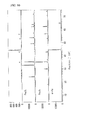
- this apparatus includes a table 1 that supports a heat-treated compact 100 to be a dust core, a working tool 2 that machines the heat-treated compact 100, a power supply 3, an anode wire 4 that connects the power supply 3 to the heat-treated compact 100 serving as an anode, a cathode wire 6 that connects the power supply 3 to a first counter electrode 5 serving as a cathode, a conductive fluid nozzle 7 that supplies a conductive fluid 7L between the working tool and the cathode, and a grinding fluid nozzle 8 that supplies a grinding fluid 8L between the working tool and the heat-treated compact.
- the heat-treated compact 100 is machined while an electric current is supplied between the anode and the cathode.
- the table 1 is a base that supports the heat-treated compact 100 to be machined with the working tool 2. At least one of the table 1 and the working tool 2 includes a moving mechanism (not shown) so that the positions of the table I and working tool 2 can be relatively changed.
- An insulation sheet 1A for electrically insulation the table 1 from the heat-treated compact 100 is disposed on the surface of the table 1.
- the insulation sheet 1 A prevents an electric current, which is supplied to the heat-treated compact 100 from the power supply 3 through the anode wire 4, from leaking to the main body of a machining apparatus (not shown) through the table 1.
- the insulation sheet 1A may be disposed between the table 1 and the main body of the machining apparatus.
- the working tool 2 is a machining tool that removes part of the heat-treated compact 100 on the table 1 and changes the shape of the heat-treated compact 100. Examples of the working tool 2 include grinding wheels, cutting tools, chopping tools, and polishing tools.
- a metal bonded grinding wheel is illustrated as the working tool 2.
- other grinding wheels include grinding wheels that use vitrified, resinoid, rubber, silicate, shellac, electrodeposit, or magnesia as a bond.
- Diamond, cBN, alumina, and silicon carbide can be suitably used for abrasive grains.
- Examples of a grinding method that uses such grinding wheels include various methods such as surface grinding, cylindrical grinding, and internal grinding. In the drawing, a surface grinder is illustrated as an example.
- Examples of the cutting tool include a tool bit and an end mill.
- Examples of the chopping tool include a wire for wire electric discharge machining and a saw wire.
- Examples of the polishing tool include a polishing surface plate and a polishing buff.
- the working tool 2 is preferably conductive.
- most of cutting tools are made of a conductive material such as a high-speed steel or a cemented carbide.
- Chopping tools are also normally made of a metal and thus have conductivity.
- a metal bonded grinding wheel and a resin/metal bonded grinding wheel have conductivity.
- Cast iron, cobalt, bronze, steel, tungsten, and nickel can be suitably used as a metal that is utilized for a bond of the grinding wheels.
- the working tool 2 does not serve as a cathode, the working tool 2 does not necessarily have conductivity.
- the constituent metal of the working tool 2 for example, the element added to cast iron is at least one element selected from Al, Si, Ti, Mg, Ca, Cr, Zr, P, and B.
- the additional element diffuses to soft magnetic particles constituting a heat-treated compact, and the additional element eluted from the soft magnetic particles forms an insulation layer on a machined surface of the heat-treated compact in the form of at least one of an oxide and a hydroxide.
- the insulation layer containing the additional element is expected to have improved insulation property and improved mechanical properties.
- the power supply 3 supplies an electric current between the anode and the cathode through the anode wire 4 and the cathode wire 6.
- the power supply 3 is preferably a pulsed power supply that can supply a desired electric current between the electrodes at a desired voltage.
- the anode wire 4 supplies an electric current from the power supply 3 to the heat-treated compact 100 serving as an anode.
- the heat-treated compact 100 is obtained as follows. Composite magnetic particles including soft magnetic particles and insulation coatings that cover the peripheries of the soft magnetic particles are compacted to form a compact, and then the compact is heat-treated to obtain the heat-treated compact 100.
- the heat-treated compact 100 serving as the anode is placed on the table 1 constituting the production apparatus.
- the cathode wire 6 connects the power supply 3 to the first counter electrode 5 serving as a cathode.
- the cathode wire 6 and the anode wire 4 form a current path of power supply-anode (heat-treated compact)-working tool-cathode (first counter electrode)-power supply.
- the first counter electrode 5 is a component disposed so as to face the working tool 2 with a certain distance therebetween.
- the first counter electrode 5 is composed of a material having conductivity and proper mechanical strength, such as copper, stainless steel, or graphite.
- the shape of the first counter electrode 5 is determined in accordance with the shape of the working tool 2, and is preferably a shape that achieves a uniform distance between the working tool and the first counter electrode.
- the first counter electrode 5 is constituted by a block whose surface facing the working tool 2 is an arc-like curved shape that corresponds to the outer peripheral surface of the grinding wheel.
- the distance between the first counter electrode 5 and the working tool 2 is preferably about 0.05 to 0.3 mm.
- At least one of the first counter electrode 5 and the working tool 2 preferably includes a moving mechanism so that the distance can be kept constant by relatively moving the first counter electrode 5 and the working tool 2.
- the conductive fluid nozzle 7 supplies a conductive fluid 7L sent from the supply source (not shown) of the conductive fluid 7L between the working tool and the cathode.
- the conductive fluid 7L needs to have electrical conductivity so that the electrical connection between the working tool and the cathode can be achieved by supplying the conductive fluid 7L between the working tool and the cathode.
- a conductive fluid having an electrical conductivity of 2 mS/cm or more is suitably used.
- the conductive fluid 7L is a weakly alkaline (about pH 11) water-soluble fluid, which is not an electrolytic solution having high corrosiveness, excessive corrosion is not caused on the working tool 2 and the heat-treated compact 100.
- the conductive fluid 7L may be a commercially available grinding fluid as long as it has desired conductivity and alkalinity.
- the grinding fluid nozzle 8 supplies a grinding fluid 8L sent from the supply source (not shown) of the grinding fluid between the working tool and the heat-treated compact.
- the grinding fluid 8L may be basically any grinding fluid as long as it can reduce the friction between the working tool 2 and the heat-treated compact 100.
- the grinding fluid 8L preferably has conductivity.
- the grinding fluid 8L may be a fluid that is the same as or different from the conductive fluid 7L.
- a conductive fluid/grinding fluid may be supplied from a single fluid supply source and, if necessary, the conductive fluid/grinding fluid may be supplied between the heat-treated compact and the first counter electrode and between the working tool and the heat-treated compact from a plurality of nozzles.
- the grinding fluid 8L is the same fluid as the conductive fluid 7L.
- a method for producing a dust core with the above-described apparatus includes a preparation step of a heat-treated compact and a machining step of the heat-treated compact.
- the preparation step soft magnetic particles having an insulation coating are compacted to obtain a compact, and then the compact is heat-treated to prepare a heat-treated compact.
- the machining step part of the heat-treated compact is removed using a working tool while an electric current is supplied with a conductive fluid between the heat-treated compact serving as an anode and a first counter electrode serving as a cathode.
- Soft magnetic particles are preferably made of a metal containing 50% or more by mass of iron, which is, for example, pure iron (Fe).
- an iron alloy such as at least one alloy selected from an Fe-Si alloy, an Fe-Al alloy, an Fe-N alloy, an Fe-Ni alloy, an Fe-C alloy, an Fe-B alloy, an Fe-Si-B alloy, an Fe-Co alloy, an Fe-P alloy, an Fe-Ni-Co alloy, and an Fe-Al-Si alloy can be used.
- pure iron containing 99% or more by mass of Fe is preferably used in terms of magnetic permeability and magnetic flux density.
- the average particle size of the soft magnetic particles is preferably 30 ⁇ m or more and 500 ⁇ m or less.
- the average particle size of the soft magnetic particles is 30 ⁇ m or more, an increase in the coercive force and hysteresis loss of a dust core produced using a soft magnetic material can be suppressed without reducing the fluidity of the soft magnetic material.
- the average particle size of the soft magnetic particles is 500 ⁇ m or less, the eddy-current loss generated in a high frequency range of 1 kHz or more can be effectively reduced.
- the average particle size of the soft magnetic particles is more preferably 40 ⁇ m or more and 300 ⁇ m or less.
- the average particle size mentioned herein means a particle size of a particle at which the cumulative sum of the masses of particles from the smallest particle reaches 50% of the total mass in a particle size histogram, i.e., a 50% particle size.
- the insulation coating that coats the surface of the soft magnetic particles can suppress the contact between the soft magnetic particles and can reduce the relative permeability of the compact. Furthermore, the presence of the insulation coating can suppress the flow of an eddy current between the soft magnetic particles and thus can reduce the eddy-current loss of a dust core.
- the insulation coating is not particularly limited as long as it has good insulation property.
- a phosphate, a titanate, a silicate, and a magnesia can be suitably used.
- an insulation coating composed of a phosphate has good deformability. Therefore, even if the soft magnetic particles are deformed when a dust core is produced by compacting the soft magnetic particles, the insulation coating can follow the deformation.
- a phosphate film has high adhesion to iron-based soft magnetic particles and thus does not easily come off from the surfaces of the soft magnetic particles.
- the phosphate include metal phosphate compounds such as iron phosphate, manganese phosphate, zinc phosphate, and calcium phosphate.
- a silicone film may be directly formed on the periphery of the soft magnetic particles or may be formed, as an outer insulation coating, on an inner insulation coating composed of a phosphate or the like.
- the silicone film is suitably composed of a silicone that cures through a hydrolysis/polycondensation reaction.
- a compound represented by Si m (OR) n (m and n are each a natural number) can be used.
- OR represents a hydrolytic group. Examples of the hydrolytic group include an alkoxy group, an acetoxy group, a halogen group, an isocyanate group, and a hydroxyl group. Examples of the alkoxy group include methoxy, ethoxy, propoxy, isopropoxy, butoxy, sec-butoxy, and tert-butoxy.
- a silicone film formed through the hydrolysis/polycondensation of a resin material has high deformability, fractures and cracks are not easily caused when a soft magnetic material is pressurized and the silicone film is hardly detached from the surface of the insulation coating.
- the silicone film has high heat resistance, good insulation property can be maintained even if the temperature of a heat treatment performed after the compaction of the soft magnetic material is high.
- the silicone film also protects the inner insulation coating from heat or the like.
- Such a silicone film can be formed by mixing soft magnetic particles or soft magnetic particles having a phosphate film with a resin material in a heating atmosphere of 80 to 160°C. This mixing provides a state in which the resin material coats the surface of each of the soft magnetic particles. Water molecules contained in the mixing atmosphere or water of hydration (if the phosphate film contains water of hydration) causes the hydrolysis/polycondensation of the resin material and thus the silicone film is formed.
- the thickness of the insulation coating is preferably 10 nm or more and 1 ⁇ m or less.
- the thickness of the insulation coating is 10 nm or more, the contact between the soft magnetic particles can be suppressed and the energy loss due to an eddy current can be effectively suppressed.
- the thickness of the insulation coating is 1 ⁇ m or less, the ratio of the insulation coating in the composite magnetic particles is prevented from excessively increasing. Thus, the magnetic flux density of the composite magnetic particles can be prevented from significantly decreasing.
- the above-described soft magnetic particles having an insulation coating are typically formed into a compact by being inserted into a mold having a desired shape and then by being compacted under pressure.
- the pressure can be suitably selected. For example, if a dust core used for electrical appliances equipped with solenoid valves, motors, or power supply circuits is produced, the pressure is preferably about 600 to 1400 MPa (and more preferably 800 to 1000 MPa).
- the compact undergoes a heat treatment step.
- the distortion and dislocation introduced into the soft magnetic particles in the compaction process are removed, and the adhesion between the soft magnetic particles through the insulation coating is increased.
- the heat treatment temperature is preferably 300°C or higher, more preferably 400°C or higher, and particularly preferably 450°C or higher.
- the upper limit of the heat treatment temperature is about 900°C. At such a heat treatment temperature, distortion can be removed and also lattice defects such as dislocation introduced into the soft magnetic particles under pressure can be removed. This eases the movement of domain walls of a dust core obtained and decreases the coercive force Hc, which contributes to a reduction in hysteresis loss.
- machining for removing part of the heat-treated compact 100 with the working tool 2 such as a grinding wheel is performed so that the heat-treated compact 100 has a desired shape.
- part of an insulation coating 120 formed on soft magnetic particles 110 in composite magnetic particles 100P that constitute the heat-treated compact 100 is removed with a grinding wheel and thus a machined surface 100F is formed.
- the soft magnetic particles 110 not covered with the insulation coating 120 are exposed at the machined surface 100F.
- Figures 2(B) to 2(D) are enlarged views of a region enclosed with a broken line in Fig. 2(A) . If the heat-treated compact is simply ground with a grinding wheel, as shown in Fig.
- the soft magnetic particles 110 that are adjacent to each other facing the machined surface 100F may be connected to each other through a bridge portion 110B due to the plastic deformation during the grinding. Therefore, in the machining, the bridge portion 110B is removed by supplying an electric current while providing a conductive fluid between the heat-treated compact serving as an anode and the first counter electrode serving as a cathode.
- the reason why the bridge portion 110B can be removed in the machining step is assumed to be as follows.
- the working tool 2 is in contact with the heat-treated compact 100 to be machined.
- some abrasive grains are in contact with the heat-treated compact 100 while tiny spaces are formed between the heat-treated compact 100 and other abrasive grains or a bond.
- a grinding fluid 8L also serving as a conductive fluid 7L is present in the spaces ( Fig. 1 ). Therefore, when a pulsed current is supplied to the heat-treated compact 100 from the power supply 3, a constituent element (e.g., Fe) of the soft magnetic particles is eluted at the machined surface through electrolysis.
- a constituent element e.g., Fe
- the pulsed current is preferably supplied at a pulsed voltage of about 40 to 200 V and an average current of about 0.5 to 20 A.
- a coating step of forming an insulation layer that contains at least one of an oxide and a hydroxide of the element eluted through electrolysis is preferably performed.
- This coating step can be performed successively after the machining step by only changing the relative positions of the working tool 2 and the heat-treated compact 100 to provide a certain distance therebetween while supplying an electric current.
- the heat-treated compact 100 is not ground, and soft magnetic particles at the machined surface are eluted through electrolysis. An element eluted from the soft magnetic particles is oxidized or hydroxylated and thus an oxide film or a hydroxide film is formed on the machined surface. As shown in Fig.
- the oxide film or the hydroxide film becomes an insulation layer 130 that covers the machined surface 100F of the soft magnetic particles from which the insulation coating 120 has been removed. Therefore, on the surface of the heat-treated compact, the soft magnetic particles 110 can be prevented from being exposed.
- the insulation layer 130 is formed while containing at least one of an oxide or a hydroxide of the element eluted from the soft magnetic particles, the insulation layer 130 is normally composed of a material different from that of the insulation coating 120 that covers the soft magnetic particles 110.
- the insulation layer 130 is also formed during the removal step.
- the formed insulation layer 130 is often removed with the working tool.
- the coating step is preferably performed while a certain distance is provided between the working tool 2 and the heat-treated compact 100 after the removal step.
- zero-cut (spark-out) in which the depth of cut becomes zero is normally performed just before the completion of the process.
- the working tool 2 is in substantially noncontact with the heat-treated compact 100 and the machining of the heat-treated compact substantially does not proceed.
- the insulation layer 130 is easily formed and the machined surface can be covered with the insulation layer 130 with certainty.
- the distance between the working tool 2 and the heat-treated compact 100 that are in noncontact with each other is preferably about 0.000 to 0.3 mm.
- the constituent element of the soft magnetic particles 110 can be eluted and the insulation layer can be properly formed.
- the lower limit of the distance is often about 0.005 mm. This restriction of the distance is common in other embodiments described below.
- an electrical discharge is generated between the working tool 2 and the heat-treated compact 100. Therefore, even if the bridge portion 110B remains left after the removal step, the bridge portion 110B can be removed with certainty by the electrical discharge or electrolysis in the coating step.
- a dust core of the present invention is produced through the steps above.
- the dust core is a dust core obtained by compacting soft magnetic particles having an insulation coating.
- the dust core includes a machined surface on at least part of an outer peripheral surface of the core, the machined surface being formed by removing part of the core with a working tool.
- the soft magnetic particles adjacent to each other along the machined surface are isolated from each other through the insulation coating on the machined surface.
- the bridge portion can be removed in the removal step, the soft magnetic particles 110 that are adjacent to each other facing the machined surface 100F are electrically insulated from each other in an independent manner as shown in Fig. 2(B) or Fig. 2(C) .
- the eddy-current loss can be reduced.
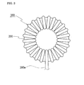
- the above-described dust core can be used for a coil component of electrical appliances equipped with solenoid valves or power supply circuits.
- an example of the coil component is a choke coil including a toroidal core 200 and a coil 300 formed by winding a winding 300w on the periphery of the toroidal core 200.
- the toroidal core 200 is constituted by the above-described dust core. Therefore, soft magnetic particles constituting the toroidal core 200 are sufficiently insulated from each other, and the eddy-current loss generated when the coil 300 is exited can be reduced.
- the case where the first counter electrode facing the working tool is used as a cathode has been described.
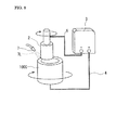
- a production apparatus of a dust core in which the first counter electrode is removed and the working tool is directly used as a cathode and a method for producing a dust core will be described with reference to Fig. 4 .
- the main difference from the first embodiment is that the working tool is used as a cathode.
- the description below will be made focusing on the difference.
- Other apparatus configuration is the same as that of the first embodiment unless otherwise specified.
- a cathode wire 6 of this embodiment is connected to a working tool 2.
- the cathode wire 6 seems to be connected to the periphery of a disc-shaped grinding wheel, but is, in reality, electrically connected to the grinding wheel through a rotating shaft of the grinding wheel using a brush electrode or the like.
- the working tool 2 of this embodiment has conductivity because it is used as a cathode.
- a conductive fluid nozzle 7 is disposed so as to supply a conductive fluid 7L between the working tool 2 and a heat-treated compact 100.
- the conductive fluid 7L reduces the friction between the working tool 2 and the heat-treated compact 100 and also functions as a grinding fluid that cools the heat-treated compact 100.
- machining is performed while an electric current is supplied between the anode and the cathode, that is, between the heat-treated compact and the working tool.
- the working tool 2 and the heat-treated compact 100 are in contact with each other, and electrolysis and electrical discharge are generated at the contact interface as in the first embodiment. Therefore, it is believed that the bridge portion 110B shown in Fig. 2(D) is removed due to the electrolysis and the heat generation caused by the electrical discharge.
- the soft magnetic particles that are adjacent to each other along the machined surface 100F can be isolated from each other through an insulation coating 120 ( Fig. 2(B) ).
- a space is created between the working tool 2 and the heat-treated compact 100 so that they are in noncontact with each other.
- the conductive fluid 7L is supplied to the space while an electric current is supplied.
- an electric current is supplied.
- the soft magnetic particles on the machined surface of the heat-treated compact 100 are electrolyzed, and an insulation layer containing an element of the eluted soft magnetic particles is formed on the machined surface.
- an insulation layer 130 is formed on the machined surface and thus a state in which the soft magnetic particles on the machined surface are covered with the insulation layer can be achieved ( Fig. 2(C) ).
- the first counter electrode 5 used in the first embodiment is not required.
- the conductive fluid 7L grinding fluid
- the conductive fluid 7L may be supplied between the working tool 2 and the heat-treated compact 100.
- the case where the first counter electrode facing the working tool is used as a cathode has been described.
- the case where the working tool is used as a cathode has been described.
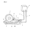
- a production apparatus of a dust core in which a second counter electrode facing the heat-treated compact is used as a cathode and a method for producing a dust core will be described with reference to Fig. 5 .
- the main difference from the first embodiment is that a second counter electrode 9 is used as a cathode.
- Other apparatus configuration is the same as that of the first embodiment unless otherwise specified.
- a second counter electrode 9 is disposed independently from a working tool 2 and the counter electrode 9 is held so that a certain distance is provided between the counter electrode 9 and the heat-treated compact 100.
- the heat-treated compact 100 is machined with the working tool 2 while supplying an electric current and providing a conductive fluid 7L between the heat-treated compact 100 serving as an anode and the counter electrode 9 serving as a cathode.
- the second counter electrode 9 is composed of the same material as that of the first counter electrode of the first embodiment.
- the shape of the counter electrode 9 is determined in accordance with the shape of the heat-treated compact 100 serving as an anode, and is preferably a shape that achieves a uniform distance between the anode and the counter electrode.
- the counter electrode 9 is constituted by a block.
- the distance between the counter electrode 9 and the anode (heat-treated compact 100) is preferably about 0.000 to 0.3 mm. Normally, the lower limit of the distance is often about 0.005 mm. This restriction of the distance is common in other embodiments described below.
- the distance is preferably kept constant during the removal step and coating step by disposing a moving mechanism (not shown) that changes the relative positions of the counter electrode 9 and heat-treated compact 100.
- a facing portion of the working tool and the heat-treated compact is different from a facing portion of the second counter electrode and the heat-treated compact. Therefore, an electric current is not necessarily supplied to the working tool 2 or may be supplied as in the first and second embodiments. In this embodiment, an electric current is not supplied to the working tool 2.
- the machined surface and the second counter electrode 9 need to be caused to face each other with a certain distance therebetween after grinding and an electric current needs to be supplied therebetween.
- a bridge portion that connects adjacent soft magnetic particles to each other is formed on the machined surface of the heat-treated compact 100.
- the bridge portion can be removed through at least one of electrical discharge and electrolysis by relatively moving the second counter electrode 9 and the heat-treated compact 100 after grinding, causing the machined surface to face the second counter electrode 9 with a certain distance therebetween, and supplying an electric current therebetween.
- an insulation layer containing at least one of an oxide and a hydroxide of an element eluted from soft magnetic particles can be formed on the machined surface of the heat-treated compact 100 that faces the counter electrode 9. Consequently, the soft magnetic particles facing the machined surface can be insulated from each other and can be prevented from being exposed.
- an insulation layer can be formed on the damaged portion to repair the insulation coating.
- the insulation coating may be damaged when soft magnetic particles are compacted or the resultant compact is drawn out of a mold. The soft magnetic particles are exposed from the damaged portion. Therefore, an insulation layer can be formed on the damaged portion by causing the counter electrode 9 to face the damaged portion and supplying a pulsed current between the heat-treated compact and the second counter electrode.
- an electric current is supplied while keeping the distance between the counter electrode 9 and the heat-treated compact 100 and changing the relative positions thereof, the insulation coating can be easily repaired in a wide area of the surface of the heat-treated compact 100.
- the electrical connection between soft magnetic particles adjacent to each other can be suppressed.
- the area of an exposed portion of the soft magnetic particles can be reduced on the machined surface and even on a surface other than the machined surface, which provides a coil component having lower eddy-current loss.
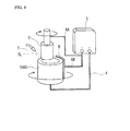
- a method for producing a dust core of the present invention in which the second counter electrode in the third embodiment also functions as a conductive fluid nozzle will now be described with reference to Fig. 6 .
- the difference between this embodiment and the third embodiment is that a conductive fluid nozzle 7 also functions as a second counter electrode 9.
- Other points are basically the same as those of the third embodiment.
- a pulsed current is supplied between the heat-treated compact 100 serving as an anode and the conductive fluid nozzle 7 also serving as the second counter electrode 9 (cathode).
- the conductive fluid nozzle 7 needs to be composed of a conductive material.
- the conductive fluid nozzle 7 preferably has a flat shape in which the outer peripheral surface of the nozzle is a plane surface, so that the conductive fluid nozzle 7 and the heat-treated compact 100 face each other in a larger area.
- the nozzle 7 is illustrated in a simplified manner. Nozzle outlets of the conductive fluid 7L are arranged on the left end of the conductive fluid nozzle 7 and furthermore nozzle outlets of the conductive fluid 7L are arranged on the surface facing the heat-treated compact 100.
- the bridge portion can also be removed and an insulation layer can also be formed in this embodiment.
- the second counter electrode is not required, which can simplify the apparatus configuration.
- a first counter electrode 5 serves as a cathode and a rod-shaped heat-treated compact 100B serves as an anode.
- the first counter electrode 5 and the heat-treated compact 100B are each arranged so as to face a disc-shaped grinding wheel, which is a working tool 2, with a certain distance therebetween.
- the first counter electrode 5 has an arc-like curved concave surface that corresponds to the outer peripheral surface of the cylindrical working tool, and is connected to a negative pole of a power supply 3 through a cathode wire 6.
- the heat-treated compact 100B has one end that is coaxially supported by an insulation jig 11 so as to be rotatable using the axis of the jig 11 as a rotation axis.
- the rotation axis of the grinding wheel and the rotation axis of the heat-treated compact 100B are arranged in parallel. In the drawing, the rotational directions of the grinding wheel and the heat-treated compact 100B are the same, but the rotational directions may be opposite.
- the heat-treated compact 100B has another end that is supported by a support (not shown), and the support is connected to a positive pole of the power supply 3 through an anode wire 4.
- the electrical connection between the support and the heat-treated compact 100B can be made using a sliding contact such as a brush.
- a conductive fluid 7L is supplied between the working tool 2 and the first counter electrode 5 from a conductive fluid nozzle 7.
- a grinding fluid 8L is supplied between the working tool 2 and the heat-treated compact 100B from a grinding fluid nozzle 8.
- a constituent element of soft magnetic particles constituting the heat-treated compact 100B can be eluted through electrolysis or part of the soft magnetic particles can be removed through electrical discharge.
- the constituent element of the soft magnetic particles eluted through electrolysis is oxidized or hydroxylated to form an insulation layer on the ground surface. This can provide the insulation between the soft magnetic particles.
- the insulation layer can be easily formed by relatively moving the working tool 2 and the heat-treated compact 100B in an axial direction while holding a certain distance between the working tool 2 and the heat-treated compact 100B.
- a round-bar grinding wheel with a shaft is used as a working tool 2, and a hollow cylindrical heat-treated compact 100C is to be machined.
- the working tool 2 and the heat-treated compact 100C are arranged in a vertical direction. They are each independently supported by a rotatable supporting mechanism (not shown).
- the outer diameter of the working tool 2 is smaller than the inner diameter of the heat-treated compact 100C.
- the heat-treated compact 100C is ground by inserting the working tool 2 inside the heat-treated compact 100C and then pressing the outer peripheral surface of the tool 2 against the inner peripheral surface of the heat-treated compact 100C.
- a conductive fluid 7L is supplied from a conductive fluid nozzle 7 to a contact surface between the working tool 2 and the heat-treated compact 100C.
- the conductive fluid 7L is a grinding fluid.
- the working tool 2 is connected to a negative pole of a power supply 3 through a cathode wire 6.
- the heat-treated compact 100C is connected to a positive pole of the power supply 3 through an anode wire 4. That is, in this embodiment, the working tool 2 itself functions as a cathode as in the second embodiment.
- a constituent element of soft magnetic particles constituting the heat-treated compact 100C can be eluted through electrolysis or part of the soft magnetic particles can be removed through electrical discharge.
- the constituent element of the soft magnetic particles eluted through electrolysis is oxidized or hydroxylated to form an insulation layer on the ground surface.
- This embodiment is a modification of the sixth embodiment and differs from the sixth embodiment in that a second counter electrode 9 is disposed on the periphery of the heat-treated compact 100C to perform a re-insulation coating step.
- the description below will be made focusing on the difference.
- the cathode wire 6 is branched at the midway.
- a branched wire 6A is connected to the working tool 2 as in the sixth embodiment whereas a branched wire 6B is connected to a second counter electrode 9 arranged on the periphery of the heat-treated compact 100C with a certain distance therebetween.
- the heat-treated compact 100C serves as an anode and the working tool 2 and second counter electrode 9 serve as cathodes.
- the second counter electrode 9 is constituted by an arc-like piece having a curved concave surface that corresponds to the outer peripheral surface of the heat-treated compact 100C.
- the outer peripheral surface of the heat-treated compact 100C is not a surface to be ground.
- the insulation coating of soft magnetic particles is often damaged due to the sliding contact with the mold or the like. Therefore, even if a damaged portion of an insulation coating is present on the outer peripheral surface of the heat-treated compact 100C, by supplying an electric current in the apparatus of this embodiment, a layer containing at least one of an oxide and a hydroxide of a constituent element of soft magnetic particles can be formed on the damaged portion. As a result, the insulation coating can be repaired. This can provide sufficient insulation between the soft magnetic particles.
- the insulation coating can be repaired across the entire outer peripheral surface of the compact 100C by rotating the heat-treated compact 100C.
- the bridge portion on the inner peripheral surface of the heat-treated compact 100C is removed during grinding.
- a layer containing at least one of an oxide and a hydroxide of a constituent element of the soft magnetic particles can be formed on the ground surface.
- surface grinding was performed on a heat-treated compact using the surface grinder of the first embodiment.
- surface grinding was performed on a heat-treated compact without supplying a pulsed current.
- the machined surface after grinding was analyzed by thin film XRD, and the surface resistance of the machined surface was measured.
- the surface resistance (electrical resistance) was also measured on a heat-treated compact that was not subjected to grinding.
- the grinding conditions were as follows. Just before the completion of grinding, an electric current was supplied for 120 seconds while holding a distance of 0.01 mm between a grinding wheel and the heat-treated compact.
- the surface resistance was measured by a four-terminal four-probe method using Resistivity meter Loresta GP manufactured by Dia Instruments Co., Ltd.
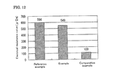
- Figure 12 is a graph showing the results.
- the surface resistance of the machined surface in the example was substantially equal to that in the reference example in which grinding was not performed. Therefore, it is believed that the insulation between soft magnetic particles in the dust core produced in the example was almost the same as that in the reference example in which grinding was not performed. In contrast, the surface resistance of the machined surface in the comparative example was significantly decreased to about less than one-fifth the surface resistance in the reference example, which means that the insulation between soft magnetic particles is insufficient.
- Three dust cores were produced using the apparatus of the first embodiment in the same manner as in Example 1.
- a heat-treated compact was ground while a pulsed current was supplied.
- a heat-treated compact was ground without supplying a pulsed current.
- grinding was not performed.
- Each of the cores was formed into a ring-shaped test piece, and the test piece was subjected to winding to obtain a measurement component. The magnetic properties of the measurement component were measured.
- the machining conditions of the dust cores were as follows. After the grinding, an electric current was supplied for 30 seconds with a distance of 0.005 mm between the heat-treated compact and the grinding wheel.
- the magnetic properties of the measurement component were measured using AC-BH Curve Tracer (manufactured by METRON, Inc.).
- the frequency curve of iron loss was fitted by the least-squares method using the three formulae below to calculate the hysteresis loss coefficient Kh (mWs/kg) and the eddy-current loss coefficient Ke (mWs 2 /kg) at the excitation magnetic flux density Bm.
- Table I shows the results.
- the values in Table I are relative evaluation values when the value in the reference example is assumed to be 100%.
- a low value means a low loss, which is preferred.
- Iron loss Hysteresis loss + Eddy - current loss
- Hysteresis loss Hysteresis loss coefficient ⁇ Frequency
- Eddy - current loss Eddy - current loss coefficient ⁇ Frequency 2
- the iron loss, in particular, the eddy-current loss in the example was significantly reduced compared with that in the comparative example. That is, it is believed that the insulation between soft magnetic particles is sufficiently ensured.
- the periphery of a columnar heat-treated compact was ground using the cylindrical grinder of the fifth embodiment.
- grinding was performed on the same heat-treated compact under the same conditions without supplying a pulsed current.
- the surface resistance of the machined surface after grinding was measured, and ESCA (electron spectroscopy for chemical analysis) was performed in the depth direction from the machined surface.
- the surface resistance was measured using the same apparatus by the same method as in Example 1.
- the surface resistance was also measured on a heat-treated compact that was not subjected to grinding (reference example).
- the element concentration was analyzed to a depth of 500 nm from the machined surface using Quantum 2000 manufactured by ULVAC-PHI, Inc.
- the grinding conditions were as follows. After the completion of grinding, an electric current was supplied for 60 seconds while holding a distance of 0.000 mm between a grinding wheel and the heat-treated compact, that is, holding a zero-cut state.
- the surface resistance in the reference example which was an unprocessed heat-treated compact
- the surface resistance in the example was 7000 ⁇ m on average.
- the surface resistance in the comparative example was 120 ⁇ m on average.
- the surface resistance in the example was higher than that in the reference example, which was an unprocessed heat-treated compact.
- the surface resistance in the comparative example was less than one-fifth the surface resistance in the reference example. It is assumed that the insulation coating of composite magnetic particles constituting the compact was damaged.
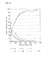
- Figure 13 shows the measurement results of ESCA in the example.
- oxygen was detected in a range of about 200 nm, particularly about 100 nm, from the machined surface in the depth direction.
- Iron and its oxide which were materials of soft magnetic particles, were confirmed to be present. It is also believed that Fe was present in the form of an oxide or a hydroxide from the energy state of a Fe peak (not shown). It is believed that the carbon found in this graph was incidental impurities during measurement.
- the graph of the comparative example is not shown, peaks of elements other than iron and incidental impurities were not detected. Therefore, it is believed that a film composed of an oxide or hydroxide was not formed on the machined surface in the comparative example.
- the inner surface of a cylindrical heat-treated compact was ground using the internal grinder of the seventh embodiment.
- grinding was performed on the same heat-treated compact under the same conditions without supplying a pulsed current.
- the surface resistance of the outer peripheral surface of the workpiece and the iron loss were measured.
- the outer peripheral surface of the heat-treated compact is not ground, but the insulation coating covering the soft magnetic particles is damaged when a compact before heat treatment is drawn from a mold. Therefore, a re-insulation coating step was performed to form a layer composed of at least one of an oxide and a hydroxide by supplying an electric current while a second counter electrode faces the periphery of the heat-treated compact.
- the surface resistance was measured using the same apparatus by the same method as in Example 1.
- the surface resistance was also measured on the outer peripheral surface of a heat-treated compact before the re-insulation coating step.
- the iron loss was measured by the same method as in Example 2.
- the grinding conditions were as follows. After the completion of grinding, an electric current was supplied for 180 seconds while holding a distance of 0.001 mm between a grinding wheel and the heat-treated compact and between the second counter electrode and the heat-treated compact.
- the surface resistance of the heat-treated compact before the re-insulation coating step was 2100 ⁇ m on average whereas the surface resistance of the heat-treated compact after the re-insulation coating step was 10000 ⁇ m on average.
- an insulation layer containing at least one of an oxide and a hydroxide of the constituent element of soft magnetic particles was formed on a portion where the insulation coating came off, and thus the surface resistance was higher than that of the heat-treated compact before the re-insulation coating step.
- Table II shows the measurement results of iron loss.
- the iron loss in the example was significantly reduced compared with that in the comparative example in which typical internal grinding was performed without supplying an electric current to a grinding wheel and also a second counter electrode was not disposed.
- the eddy-current loss was significantly reduced. It is also found that the loss in the example was as low as that in the reference example in which the internal grinding (re-insulation coating step) was not performed and compaction was performed after a lubricant was applied to the outer peripheral surface to prevent seizing caused by drawing from a mold.
- a heat-treated compact was ground or cut using the machining apparatus of each of the embodiments shown in Tables III to VI, and subsequently an electric current was supplied while holding a certain distance between the tool and the workpiece.
- the surface resistance of the machined surface of the workpiece after the current-supplying treatment was measured.
- the surface resistance was measured using the same apparatus by the same method as in Example 1.
- the result is expressed as the ratio of the surface resistance after machining to the surface resistance before machining (reference example).
- a ratio of more than 100% means that the surface resistance was improved compared with that before machining.
- the ratio is preferably 20% or more (1/5 or more of the surface resistance before machining) and more preferably 100% or more.
- the distance between the tool and the heat-treated compact after grinding (cutting) and the current-supplying conditions are shown in Tables.
- the internal grinding with a column-shaped grinding wheel has been described.
- the machining apparatuses used in Examples 13 and 14 shown in Tables V and VI are obtained by replacing the column-shaped grinding wheel with each of cutting tools.
- Example No. Grinding wheel Heat-treated compact Abrasive grain Grain size Bond Additive Particle size( ⁇ m) Soft magnetic particle Insulation coating Example 5 cBN 120 Bronze Non 300 Pure iron Magnesia
- Example 6 Diamond 800 Vitrified Non 200 Pure iron Phosphate
- Example 7 cBN 170 Resin Non 30 Fe-Si-Al Silicate
- Example 8 Alumina 80 (Typical grinding wheel) Non 70 Fe-Si Silicone
- Example 9 Silicon carbide 200 (Typical grinding wheel) Non 150 Pure iron Phosphate
- Example 10 cBN 200 Nickel Ti, Mg 200 Fe-Ni Silicate Example 11 Diamond 325 Cast iron Non 250 Pure iron Phosphate
- Example 12 cBN 120 Bronze Non 350 Pure iron Magnesia
- Example No. Machining conditions Supply of electric current Surface resistance (%) Embodiment Distance between anode and cathode (mm) Voltage (V) Electric current (A) Time (sec) Machining method Corresponding drawing
- Second embodiment 0.002 150 20 10 65 Surface grinding Fig. 4
- Example 6 Third embodiment 0.010 40 1 240 50 Surface grinding Fig. 5
- Example 7 Third embodiment 0.010 200 0.5 100 97 Surface grinding Fig. 5
- Example 8 Third embodiment 0.020 150 1 150 89 Surface grinding Fig. 5
- Example 9 Third embodiment 0.010 90 4 60 105 Surface grinding Fig. 5
- Example 10 Fourth embodiment 0.300 60 2 30 91 Surface grinding Fig. 6
- Example 11 Fifth embodiment 0.000 80 8 120 353 Cylindrical grinding Fig. 7
- Example 12 Sixth embodiment 0.100 90 I 150 78 Internal grinding Fig. 8
- the surface resistance in the example was higher than the surface resistance in the reference example, which was an unprocessed heat-treated compact, or the surface resistance higher than or equal to 1/5 (20%) of the surface resistance before machining was achieved.
- the electric current is 4 A or more and the time is 60 seconds or longer, the ratio of the surface resistances easily exceeds 100%.
- the present invention can be applied to various grinders such as a centerless grinder, a profile grinder, a tool grinder, a thread grinder, a gear grinder, a free-form surface grinder, and a jig grinder, in addition to the grinders shown in the embodiments.
- a centerless grinder such as a centerless grinder, a profile grinder, a tool grinder, a thread grinder, a gear grinder, a free-form surface grinder, and a jig grinder, in addition to the grinders shown in the embodiments.
- the dust core of the present invention can be suitably used as a dust core for, for example, electrical appliances equipped with solenoid valves, motors, or power supply circuits.
- the method for producing a dust core of the present invention can be suitably used in the field of producing similar dust cores.
Landscapes
- Engineering & Computer Science (AREA)
- Power Engineering (AREA)
- Chemical & Material Sciences (AREA)
- Dispersion Chemistry (AREA)
- Manufacturing & Machinery (AREA)
- Soft Magnetic Materials (AREA)
- Powder Metallurgy (AREA)
Applications Claiming Priority (2)
| Application Number | Priority Date | Filing Date | Title |
|---|---|---|---|
| JP2010115224 | 2010-05-19 | ||
| PCT/JP2011/061243 WO2011145582A1 (fr) | 2010-05-19 | 2011-05-16 | Noyau à poudre de fer et procédé de fabrication de celui-ci |
Publications (3)
| Publication Number | Publication Date |
|---|---|
| EP2562771A1 true EP2562771A1 (fr) | 2013-02-27 |
| EP2562771A4 EP2562771A4 (fr) | 2016-08-03 |
| EP2562771B1 EP2562771B1 (fr) | 2018-10-17 |
Family
ID=44991685
Family Applications (1)
| Application Number | Title | Priority Date | Filing Date |
|---|---|---|---|
| EP11783516.5A Active EP2562771B1 (fr) | 2010-05-19 | 2011-05-16 | Procédé de fabrication d'un noyau à poudre de fer |
Country Status (5)
| Country | Link |
|---|---|
| US (1) | US8878642B2 (fr) |
| EP (1) | EP2562771B1 (fr) |
| JP (1) | JP5886541B2 (fr) |
| CN (1) | CN102576592B (fr) |
| WO (1) | WO2011145582A1 (fr) |
Cited By (1)
| Publication number | Priority date | Publication date | Assignee | Title |
|---|---|---|---|---|
| EP3355327A4 (fr) * | 2015-09-16 | 2019-03-27 | Hitachi Metals, Ltd. | Procédé de fabrication de noyau à poudre de fer |
Families Citing this family (16)
| Publication number | Priority date | Publication date | Assignee | Title |
|---|---|---|---|---|
| CN102576592B (zh) | 2010-05-19 | 2016-08-31 | 住友电气工业株式会社 | 压粉铁心及其制备方法 |
| JP4906972B1 (ja) | 2011-04-27 | 2012-03-28 | 太陽誘電株式会社 | 磁性材料およびそれを用いたコイル部品 |
| JP2012238841A (ja) | 2011-04-27 | 2012-12-06 | Taiyo Yuden Co Ltd | 磁性材料及びコイル部品 |
| EP4130329A1 (fr) * | 2011-06-30 | 2023-02-08 | Persimmon Technologies Corporation | Système et procédé de fabrication d'un matériau structuré |
| JP5032711B1 (ja) * | 2011-07-05 | 2012-09-26 | 太陽誘電株式会社 | 磁性材料およびそれを用いたコイル部品 |
| JP5082002B1 (ja) | 2011-08-26 | 2012-11-28 | 太陽誘電株式会社 | 磁性材料およびコイル部品 |
| JP2013131676A (ja) * | 2011-12-22 | 2013-07-04 | Sumitomo Electric Ind Ltd | 圧粉成形体、リアクトル用コア、リアクトル、コンバータ、及び電力変換装置 |
| JP2014120742A (ja) * | 2012-12-19 | 2014-06-30 | Sumitomo Electric Ind Ltd | 圧粉成形体、及び圧粉成形体の表面加工方法 |
| CN103521752A (zh) * | 2013-09-26 | 2014-01-22 | 秦皇岛星晟科技有限公司 | 一种金属树脂复合材料基磨轮的加工方法 |
| CN110021476B (zh) | 2014-03-13 | 2021-10-22 | 日立金属株式会社 | 压粉磁芯的制造方法以及压粉磁芯 |
| US20180079006A1 (en) * | 2015-03-27 | 2018-03-22 | Sumitomo Electric Sintered Alloy, Ltd. | Heat-treating method for compact, and dust core |
| JP2017092225A (ja) * | 2015-11-10 | 2017-05-25 | 住友電気工業株式会社 | 圧粉成形体、電磁部品、及び圧粉成形体の製造方法 |
| KR102478849B1 (ko) * | 2016-07-06 | 2022-12-19 | 삼성전자주식회사 | 화학적 기계적 연마 장치 |
| DE112018004080T5 (de) * | 2017-08-10 | 2020-04-23 | Sumitomo Electric Industries, Ltd. | Verfahren zur herstellung eines pulvermagnetkerns und verfahren zur herstellung einer elektromagnetischen komponente |
| WO2019044467A1 (fr) * | 2017-09-04 | 2019-03-07 | 住友電気工業株式会社 | Procédé de fabrication d'un noyau de poussière et poudre de matière première pour noyau de poussière |
| JP6737932B1 (ja) * | 2019-03-05 | 2020-08-12 | 住友化学株式会社 | 切削加工フィルムの製造方法 |
Family Cites Families (14)
| Publication number | Priority date | Publication date | Assignee | Title |
|---|---|---|---|---|
| JPS5350424A (en) * | 1976-10-19 | 1978-05-08 | Matsushita Electric Ind Co Ltd | Production method of transformer core |
| JPH071741B2 (ja) | 1983-07-01 | 1995-01-11 | 株式会社東芝 | 低鉄損磁性コアの製造方法 |
| JPH0675823B2 (ja) | 1988-01-22 | 1994-09-28 | 理化学研究所 | 研削加工装置 |
| JPH09180184A (ja) * | 1995-12-28 | 1997-07-11 | Kao Corp | 磁気記録媒体用基板の製造方法 |
| JP2002224916A (ja) * | 2001-01-30 | 2002-08-13 | Tokyo Seiden Kk | 鉄芯の切断方法及び切断装置 |
| JP2002235865A (ja) * | 2001-02-13 | 2002-08-23 | Isuzu Motors Ltd | 電磁弁のソレノイドコア及びその製造方法 |
| JP2005317678A (ja) | 2004-04-27 | 2005-11-10 | Fuji Electric Holdings Co Ltd | 磁気部品およびその製造方法 |
| JP4613622B2 (ja) | 2005-01-20 | 2011-01-19 | 住友電気工業株式会社 | 軟磁性材料および圧粉磁心 |
| JP4655838B2 (ja) | 2005-09-08 | 2011-03-23 | トヨタ自動車株式会社 | コアの製造方法 |
| JP4982850B2 (ja) * | 2006-10-25 | 2012-07-25 | 独立行政法人理化学研究所 | 被加工物の表面改質加工方法及び装置 |
| KR101497046B1 (ko) * | 2007-03-20 | 2015-02-27 | 엔이씨 도낀 가부시끼가이샤 | 연자성 합금 및 이를 이용한 자기부품과 이들의 제조방법 |
| JP2009283774A (ja) | 2008-05-23 | 2009-12-03 | Sumitomo Electric Ind Ltd | 軟磁性粉末 |
| JP2011181654A (ja) * | 2010-03-01 | 2011-09-15 | Kobe Steel Ltd | 圧粉磁心の表面処理方法および圧粉磁心 |
| CN102576592B (zh) | 2010-05-19 | 2016-08-31 | 住友电气工业株式会社 | 压粉铁心及其制备方法 |
-
2011
- 2011-05-16 CN CN201180004257.9A patent/CN102576592B/zh active Active
- 2011-05-16 US US13/502,985 patent/US8878642B2/en active Active
- 2011-05-16 EP EP11783516.5A patent/EP2562771B1/fr active Active
- 2011-05-16 JP JP2011109774A patent/JP5886541B2/ja active Active
- 2011-05-16 WO PCT/JP2011/061243 patent/WO2011145582A1/fr active Application Filing
Cited By (2)
| Publication number | Priority date | Publication date | Assignee | Title |
|---|---|---|---|---|
| EP3355327A4 (fr) * | 2015-09-16 | 2019-03-27 | Hitachi Metals, Ltd. | Procédé de fabrication de noyau à poudre de fer |
| US11192183B2 (en) | 2015-09-16 | 2021-12-07 | Hitachi Metals, Ltd. | Method for manufacturing powder magnetic core |
Also Published As
| Publication number | Publication date |
|---|---|
| US8878642B2 (en) | 2014-11-04 |
| JP5886541B2 (ja) | 2016-03-16 |
| CN102576592B (zh) | 2016-08-31 |
| EP2562771B1 (fr) | 2018-10-17 |
| WO2011145582A1 (fr) | 2011-11-24 |
| EP2562771A4 (fr) | 2016-08-03 |
| US20120229244A1 (en) | 2012-09-13 |
| CN102576592A (zh) | 2012-07-11 |
| JP2012004551A (ja) | 2012-01-05 |
Similar Documents
| Publication | Publication Date | Title |
|---|---|---|
| EP2562771B1 (fr) | Procédé de fabrication d'un noyau à poudre de fer | |
| US11636970B2 (en) | Method for manufacturing powder magnetic core, and powder magnetic core | |
| EP2260963B1 (fr) | Procédé et gabarit d'assemblage pour fabriquer une roue de découpe à lame externe | |
| CN103229259B (zh) | 压粉铁心、制造压粉铁心的方法以及线圈部件 | |
| TW201739929A (zh) | 燒結磁性合金之晶粒邊界工程及其衍生組合物 | |
| JP2015155143A (ja) | 超硬合金台板外周切断刃の製造方法 | |
| JP4227326B2 (ja) | 焼結希土類磁石合金からなるリング状薄板の製法 | |
| CN112695273A (zh) | 溅射靶 | |
| JP2007253277A (ja) | 研切削体及び研削体セット、これらを用いた研削装置及び研削方法 | |
| JPH0613211A (ja) | 耐食性のすぐれた永久磁石及びその製造方法 | |
| JP3755877B2 (ja) | 異形線伸線用ダイヤモンドダイス及び異形線材の製造方法 | |
| JP2014120742A (ja) | 圧粉成形体、及び圧粉成形体の表面加工方法 | |
| JP2007196307A (ja) | 研削装置、研削方法及び希土類焼結磁石の製造方法 | |
| JP2008290168A (ja) | 超砥粒ホイールおよび焼結材料の研削加工法 | |
| JP2005144643A (ja) | 磁気研磨用研磨材、加工液および磁気研磨用研磨材の製造方法 | |
| JPH06140218A (ja) | 耐衝撃性希土類コバルト磁石およびその製造方法 | |
| JPH0666173B2 (ja) | 耐食性のすぐれた永久磁石及びその製造方法 | |
| JPS6260212A (ja) | 永久磁石材料の製造方法 | |
| JPH0646603B2 (ja) | 耐食性のすぐれた永久磁石及びその製造方法 | |
| JP2007253278A (ja) | 研切削体及び研切削体セット、これらを用いた研切削装置及び研切削方法 | |
| JP5359513B2 (ja) | R−tm−b系ラジアル異方性リング磁石の製造方法 | |
| JP5975137B2 (ja) | 超硬合金台板外周切断刃 | |
| JP2005286022A (ja) | 希土類焼結磁石の製造方法及び製造装置 | |
| JP2005223317A (ja) | 永久磁石部材及びその製造方法 | |
| January | PATENTS: USA |
Legal Events
| Date | Code | Title | Description |
|---|---|---|---|
| PUAI | Public reference made under article 153(3) epc to a published international application that has entered the european phase |
Free format text: ORIGINAL CODE: 0009012 |
|
| 17P | Request for examination filed |
Effective date: 20120323 |
|
| AK | Designated contracting states |
Kind code of ref document: A1 Designated state(s): AL AT BE BG CH CY CZ DE DK EE ES FI FR GB GR HR HU IE IS IT LI LT LU LV MC MK MT NL NO PL PT RO RS SE SI SK SM TR |
|
| DAX | Request for extension of the european patent (deleted) | ||
| RIN1 | Information on inventor provided before grant (corrected) |
Inventor name: NISHIOKA, TAKAO Inventor name: UENO, TOMOYUKI |
|
| REG | Reference to a national code |
Ref country code: DE Ref legal event code: R079 Ref document number: 602011053009 Country of ref document: DE Free format text: PREVIOUS MAIN CLASS: H01F0001260000 Ipc: H01F0001240000 |
|
| RA4 | Supplementary search report drawn up and despatched (corrected) |
Effective date: 20160701 |
|
| RIC1 | Information provided on ipc code assigned before grant |
Ipc: H01F 1/24 20060101AFI20160627BHEP Ipc: H01F 3/08 20060101ALI20160627BHEP Ipc: H01F 27/255 20060101ALI20160627BHEP Ipc: H01F 41/02 20060101ALI20160627BHEP |
|
| STAA | Information on the status of an ep patent application or granted ep patent |
Free format text: STATUS: EXAMINATION IS IN PROGRESS |
|
| 17Q | First examination report despatched |
Effective date: 20170503 |
|
| GRAP | Despatch of communication of intention to grant a patent |
Free format text: ORIGINAL CODE: EPIDOSNIGR1 |
|
| STAA | Information on the status of an ep patent application or granted ep patent |
Free format text: STATUS: GRANT OF PATENT IS INTENDED |
|
| INTG | Intention to grant announced |
Effective date: 20180605 |
|
| GRAS | Grant fee paid |
Free format text: ORIGINAL CODE: EPIDOSNIGR3 |
|
| GRAA | (expected) grant |
Free format text: ORIGINAL CODE: 0009210 |
|
| STAA | Information on the status of an ep patent application or granted ep patent |
Free format text: STATUS: THE PATENT HAS BEEN GRANTED |
|
| AK | Designated contracting states |
Kind code of ref document: B1 Designated state(s): AL AT BE BG CH CY CZ DE DK EE ES FI FR GB GR HR HU IE IS IT LI LT LU LV MC MK MT NL NO PL PT RO RS SE SI SK SM TR |
|
| REG | Reference to a national code |
Ref country code: GB Ref legal event code: FG4D |
|
| REG | Reference to a national code |
Ref country code: CH Ref legal event code: EP |
|
| REG | Reference to a national code |
Ref country code: IE Ref legal event code: FG4D |
|
| REG | Reference to a national code |
Ref country code: DE Ref legal event code: R096 Ref document number: 602011053009 Country of ref document: DE Ref country code: AT Ref legal event code: REF Ref document number: 1054943 Country of ref document: AT Kind code of ref document: T Effective date: 20181115 |
|
| REG | Reference to a national code |
Ref country code: NL Ref legal event code: MP Effective date: 20181017 |
|
| REG | Reference to a national code |
Ref country code: LT Ref legal event code: MG4D |
|
| REG | Reference to a national code |
Ref country code: AT Ref legal event code: MK05 Ref document number: 1054943 Country of ref document: AT Kind code of ref document: T Effective date: 20181017 |
|
| PG25 | Lapsed in a contracting state [announced via postgrant information from national office to epo] |
Ref country code: NL Free format text: LAPSE BECAUSE OF FAILURE TO SUBMIT A TRANSLATION OF THE DESCRIPTION OR TO PAY THE FEE WITHIN THE PRESCRIBED TIME-LIMIT Effective date: 20181017 |
|
| PG25 | Lapsed in a contracting state [announced via postgrant information from national office to epo] |
Ref country code: ES Free format text: LAPSE BECAUSE OF FAILURE TO SUBMIT A TRANSLATION OF THE DESCRIPTION OR TO PAY THE FEE WITHIN THE PRESCRIBED TIME-LIMIT Effective date: 20181017 Ref country code: LV Free format text: LAPSE BECAUSE OF FAILURE TO SUBMIT A TRANSLATION OF THE DESCRIPTION OR TO PAY THE FEE WITHIN THE PRESCRIBED TIME-LIMIT Effective date: 20181017 Ref country code: NO Free format text: LAPSE BECAUSE OF FAILURE TO SUBMIT A TRANSLATION OF THE DESCRIPTION OR TO PAY THE FEE WITHIN THE PRESCRIBED TIME-LIMIT Effective date: 20190117 Ref country code: AT Free format text: LAPSE BECAUSE OF FAILURE TO SUBMIT A TRANSLATION OF THE DESCRIPTION OR TO PAY THE FEE WITHIN THE PRESCRIBED TIME-LIMIT Effective date: 20181017 Ref country code: IS Free format text: LAPSE BECAUSE OF FAILURE TO SUBMIT A TRANSLATION OF THE DESCRIPTION OR TO PAY THE FEE WITHIN THE PRESCRIBED TIME-LIMIT Effective date: 20190217 Ref country code: FI Free format text: LAPSE BECAUSE OF FAILURE TO SUBMIT A TRANSLATION OF THE DESCRIPTION OR TO PAY THE FEE WITHIN THE PRESCRIBED TIME-LIMIT Effective date: 20181017 Ref country code: HR Free format text: LAPSE BECAUSE OF FAILURE TO SUBMIT A TRANSLATION OF THE DESCRIPTION OR TO PAY THE FEE WITHIN THE PRESCRIBED TIME-LIMIT Effective date: 20181017 Ref country code: PL Free format text: LAPSE BECAUSE OF FAILURE TO SUBMIT A TRANSLATION OF THE DESCRIPTION OR TO PAY THE FEE WITHIN THE PRESCRIBED TIME-LIMIT Effective date: 20181017 Ref country code: LT Free format text: LAPSE BECAUSE OF FAILURE TO SUBMIT A TRANSLATION OF THE DESCRIPTION OR TO PAY THE FEE WITHIN THE PRESCRIBED TIME-LIMIT Effective date: 20181017 Ref country code: BG Free format text: LAPSE BECAUSE OF FAILURE TO SUBMIT A TRANSLATION OF THE DESCRIPTION OR TO PAY THE FEE WITHIN THE PRESCRIBED TIME-LIMIT Effective date: 20190117 |
|
| PG25 | Lapsed in a contracting state [announced via postgrant information from national office to epo] |
Ref country code: GR Free format text: LAPSE BECAUSE OF FAILURE TO SUBMIT A TRANSLATION OF THE DESCRIPTION OR TO PAY THE FEE WITHIN THE PRESCRIBED TIME-LIMIT Effective date: 20190118 Ref country code: RS Free format text: LAPSE BECAUSE OF FAILURE TO SUBMIT A TRANSLATION OF THE DESCRIPTION OR TO PAY THE FEE WITHIN THE PRESCRIBED TIME-LIMIT Effective date: 20181017 Ref country code: SE Free format text: LAPSE BECAUSE OF FAILURE TO SUBMIT A TRANSLATION OF THE DESCRIPTION OR TO PAY THE FEE WITHIN THE PRESCRIBED TIME-LIMIT Effective date: 20181017 Ref country code: PT Free format text: LAPSE BECAUSE OF FAILURE TO SUBMIT A TRANSLATION OF THE DESCRIPTION OR TO PAY THE FEE WITHIN THE PRESCRIBED TIME-LIMIT Effective date: 20190217 Ref country code: AL Free format text: LAPSE BECAUSE OF FAILURE TO SUBMIT A TRANSLATION OF THE DESCRIPTION OR TO PAY THE FEE WITHIN THE PRESCRIBED TIME-LIMIT Effective date: 20181017 |
|
| REG | Reference to a national code |
Ref country code: DE Ref legal event code: R097 Ref document number: 602011053009 Country of ref document: DE |
|
| PG25 | Lapsed in a contracting state [announced via postgrant information from national office to epo] |
Ref country code: CZ Free format text: LAPSE BECAUSE OF FAILURE TO SUBMIT A TRANSLATION OF THE DESCRIPTION OR TO PAY THE FEE WITHIN THE PRESCRIBED TIME-LIMIT Effective date: 20181017 Ref country code: DK Free format text: LAPSE BECAUSE OF FAILURE TO SUBMIT A TRANSLATION OF THE DESCRIPTION OR TO PAY THE FEE WITHIN THE PRESCRIBED TIME-LIMIT Effective date: 20181017 |
|
| PLBE | No opposition filed within time limit |
Free format text: ORIGINAL CODE: 0009261 |
|
| STAA | Information on the status of an ep patent application or granted ep patent |
Free format text: STATUS: NO OPPOSITION FILED WITHIN TIME LIMIT |
|
| PG25 | Lapsed in a contracting state [announced via postgrant information from national office to epo] |
Ref country code: RO Free format text: LAPSE BECAUSE OF FAILURE TO SUBMIT A TRANSLATION OF THE DESCRIPTION OR TO PAY THE FEE WITHIN THE PRESCRIBED TIME-LIMIT Effective date: 20181017 Ref country code: SK Free format text: LAPSE BECAUSE OF FAILURE TO SUBMIT A TRANSLATION OF THE DESCRIPTION OR TO PAY THE FEE WITHIN THE PRESCRIBED TIME-LIMIT Effective date: 20181017 Ref country code: SM Free format text: LAPSE BECAUSE OF FAILURE TO SUBMIT A TRANSLATION OF THE DESCRIPTION OR TO PAY THE FEE WITHIN THE PRESCRIBED TIME-LIMIT Effective date: 20181017 Ref country code: EE Free format text: LAPSE BECAUSE OF FAILURE TO SUBMIT A TRANSLATION OF THE DESCRIPTION OR TO PAY THE FEE WITHIN THE PRESCRIBED TIME-LIMIT Effective date: 20181017 |
|
| 26N | No opposition filed |
Effective date: 20190718 |
|
| PG25 | Lapsed in a contracting state [announced via postgrant information from national office to epo] |
Ref country code: SI Free format text: LAPSE BECAUSE OF FAILURE TO SUBMIT A TRANSLATION OF THE DESCRIPTION OR TO PAY THE FEE WITHIN THE PRESCRIBED TIME-LIMIT Effective date: 20181017 |
|
| REG | Reference to a national code |
Ref country code: CH Ref legal event code: PL |
|
| GBPC | Gb: european patent ceased through non-payment of renewal fee |
Effective date: 20190516 |
|
| PG25 | Lapsed in a contracting state [announced via postgrant information from national office to epo] |
Ref country code: MC Free format text: LAPSE BECAUSE OF FAILURE TO SUBMIT A TRANSLATION OF THE DESCRIPTION OR TO PAY THE FEE WITHIN THE PRESCRIBED TIME-LIMIT Effective date: 20181017 Ref country code: CH Free format text: LAPSE BECAUSE OF NON-PAYMENT OF DUE FEES Effective date: 20190531 Ref country code: LI Free format text: LAPSE BECAUSE OF NON-PAYMENT OF DUE FEES Effective date: 20190531 |
|
| REG | Reference to a national code |
Ref country code: BE Ref legal event code: MM Effective date: 20190531 |
|
| PG25 | Lapsed in a contracting state [announced via postgrant information from national office to epo] |
Ref country code: LU Free format text: LAPSE BECAUSE OF NON-PAYMENT OF DUE FEES Effective date: 20190516 |
|
| PG25 | Lapsed in a contracting state [announced via postgrant information from national office to epo] |
Ref country code: TR Free format text: LAPSE BECAUSE OF FAILURE TO SUBMIT A TRANSLATION OF THE DESCRIPTION OR TO PAY THE FEE WITHIN THE PRESCRIBED TIME-LIMIT Effective date: 20181017 |
|
| PG25 | Lapsed in a contracting state [announced via postgrant information from national office to epo] |
Ref country code: GB Free format text: LAPSE BECAUSE OF NON-PAYMENT OF DUE FEES Effective date: 20190516 Ref country code: IE Free format text: LAPSE BECAUSE OF NON-PAYMENT OF DUE FEES Effective date: 20190516 |
|
| PG25 | Lapsed in a contracting state [announced via postgrant information from national office to epo] |
Ref country code: BE Free format text: LAPSE BECAUSE OF NON-PAYMENT OF DUE FEES Effective date: 20190531 |
|
| PGFP | Annual fee paid to national office [announced via postgrant information from national office to epo] |
Ref country code: FR Payment date: 20200414 Year of fee payment: 10 |
|
| PGFP | Annual fee paid to national office [announced via postgrant information from national office to epo] |
Ref country code: IT Payment date: 20200414 Year of fee payment: 10 |
|
| PG25 | Lapsed in a contracting state [announced via postgrant information from national office to epo] |
Ref country code: CY Free format text: LAPSE BECAUSE OF FAILURE TO SUBMIT A TRANSLATION OF THE DESCRIPTION OR TO PAY THE FEE WITHIN THE PRESCRIBED TIME-LIMIT Effective date: 20181017 |
|
| PG25 | Lapsed in a contracting state [announced via postgrant information from national office to epo] |
Ref country code: MT Free format text: LAPSE BECAUSE OF FAILURE TO SUBMIT A TRANSLATION OF THE DESCRIPTION OR TO PAY THE FEE WITHIN THE PRESCRIBED TIME-LIMIT Effective date: 20181017 Ref country code: HU Free format text: LAPSE BECAUSE OF FAILURE TO SUBMIT A TRANSLATION OF THE DESCRIPTION OR TO PAY THE FEE WITHIN THE PRESCRIBED TIME-LIMIT; INVALID AB INITIO Effective date: 20110516 |
|
| PG25 | Lapsed in a contracting state [announced via postgrant information from national office to epo] |
Ref country code: FR Free format text: LAPSE BECAUSE OF NON-PAYMENT OF DUE FEES Effective date: 20210531 |
|
| PG25 | Lapsed in a contracting state [announced via postgrant information from national office to epo] |
Ref country code: MK Free format text: LAPSE BECAUSE OF FAILURE TO SUBMIT A TRANSLATION OF THE DESCRIPTION OR TO PAY THE FEE WITHIN THE PRESCRIBED TIME-LIMIT Effective date: 20181017 |
|
| PG25 | Lapsed in a contracting state [announced via postgrant information from national office to epo] |
Ref country code: IT Free format text: LAPSE BECAUSE OF NON-PAYMENT OF DUE FEES Effective date: 20200516 |
|
| P01 | Opt-out of the competence of the unified patent court (upc) registered |
Effective date: 20230515 |
|
| PGFP | Annual fee paid to national office [announced via postgrant information from national office to epo] |
Ref country code: DE Payment date: 20240328 Year of fee payment: 14 |