EP2556010B1 - Système portable de soulèvement de charges - Google Patents
Système portable de soulèvement de charges Download PDFInfo
- Publication number
- EP2556010B1 EP2556010B1 EP11766862.4A EP11766862A EP2556010B1 EP 2556010 B1 EP2556010 B1 EP 2556010B1 EP 11766862 A EP11766862 A EP 11766862A EP 2556010 B1 EP2556010 B1 EP 2556010B1
- Authority
- EP
- European Patent Office
- Prior art keywords
- lifting
- exoskeleton
- straps
- load
- lifting bar
- Prior art date
- Legal status (The legal status is an assumption and is not a legal conclusion. Google has not performed a legal analysis and makes no representation as to the accuracy of the status listed.)
- Active
Links
Images


Classifications
-
- B—PERFORMING OPERATIONS; TRANSPORTING
- B25—HAND TOOLS; PORTABLE POWER-DRIVEN TOOLS; MANIPULATORS
- B25J—MANIPULATORS; CHAMBERS PROVIDED WITH MANIPULATION DEVICES
- B25J9/00—Programme-controlled manipulators
- B25J9/0006—Exoskeletons, i.e. resembling a human figure
-
- B—PERFORMING OPERATIONS; TRANSPORTING
- B66—HOISTING; LIFTING; HAULING
- B66D—CAPSTANS; WINCHES; TACKLES, e.g. PULLEY BLOCKS; HOISTS
- B66D3/00—Portable or mobile lifting or hauling appliances
- B66D3/18—Power-operated hoists
Definitions
- Disclosed embodiments relate to portable load lifting systems.
- One known load lifting assist system utilizes an exoskeleton which incorporates fully articulated arms to allow for upper body lift assist. These arms have a similar range of motion to the user's arms and require significant sensing and actuation to ensure the system tracks the user to avoid any discomfort. Additionally, loads can be carried by utilizing a fixed load attachment which supports the load on the user, but prohibits raising or lowering the load from the fixed attachment point.
- Another known lifting assist system has a fixed load assist mechanism that is built into the infrastructure of a warehouse or other facility. Typically the lift assist mechanism in this system is permanently attached to a fixed overhead gantry. This arrangement is thus limited to use within a limited region of the warehouse or other facility.
- US Patent No. 3,964,182 discloses a mechanical shovel which comprises a digging tool, two booms and a harness.
- One of the booms is adapted to be mounted by the harness on and substantially parallel to the back of an operator so that the other boom extends forwardly of the operator.
- One of the booms supports a winding mechanism having a cable leading along the forwardly extending boom and attached to the handle of the digging tool.
- the handle of the digging tool is provided with means to activate the winding mechanism so that the shovel may be raised with the minimum of effort on the part of the operator.
- the combination of the two booms provides a particularly stable arrangement.
- Disclosed embodiments include portable load lifting systems that provide powered assisted straps or cables coupled to end-effectors for lifting and carrying or moving heavy loads.
- the portable load lifting system is a load lifting assist system that can be worn by a human user to transfer the weight of the load through the frame of the load lifting assist system to the ground or other lower surface (e.g., a floor).
- loads attached to the load lifting assist system are carried by the exoskeleton, significantly reducing the load on the user, thus reducing the risk of muscular skeletal injuries and allowing more weight to be carried by the user.
- portable load lifting assist systems that are independent of a lower extremity exoskeleton.
- the portable load lifting assist system can be worn like a backpack (e.g., secured by straps to a torso of a user).
- the portable load lifting system is operable without the need to be secured to a human user, such including a mobile unit (e.g., a cart on wheels) that provides the system its support and portability.
- disclosed embodiments include portable load lifting assist systems that include structures that allow users to raise loads up to a minimum of shoulder height while still providing lift assistance.
- the power-assisted straps or cables enable a user to safely accomplish tasks that would typically require two or more personnel to carry the load.
- the end-effectors are quickly and easily exchanged to enable lift and carriage of many different items such as boxes, containers or munitions.
- Disclosed portable load lifting assist system embodiments allow for the normal lifting range of motion of a person, and through the use of disclosed shoulder lifting devices, allows the user to raise loads to shoulder height and above while still providing significant lift assistance.
- Cantilevered weight can be used to keep the center of gravity close to the user to maintain balance and positive control of the load.
- Force sensors within the end-effectors can feed an onboard microprocessor-based controller to ensure system movement in concert with the user enabling accurate placement of objects that are lifted by the user.
- By detecting the force input by the user such as by including force sensors on the end effectors allows disclosed portable load lifting assist systems to also able to detect the user's intent (raise, lower or stabilize) and to provide the appropriate assistance to implement the user's intent via the lifting straps or cables attached to the end-effectors.
- Disclosed embodiments are described with reference to the attached figures, wherein like reference numerals, are used throughout the figures to designate similar or equivalent elements.
- the figures are not drawn to scale and they are provided merely to illustrate aspects disclosed herein.
- Several disclosed aspects are described below with reference to example applications for illustration. It should be understood that numerous specific details, relationships, and methods are set forth to provide a full understanding of the embodiments disclosed herein.
- One having ordinary skill in the relevant art, however, will readily recognize that the disclosed embodiments can be practiced without one or more of the specific details or with other methods.
- well-known structures or operations are not shown in detail to avoid obscuring aspects disclosed herein.
- Disclosed embodiments are not limited by the illustrated ordering of acts or events, as some acts may occur in different orders and/or concurrently with other acts or events. Furthermore, not all illustrated acts or events are required to implement a methodology in accordance with this Disclosure.
- Disclosed portable load lifting systems comprise a movable support structure and a load lifting mechanism secured to the movable support structure comprising a winch including a motor driven reel mechanism for reeling first and second lifting straps or cables that are secured to first and second end effectors.
- First and second handles are attached to an outside surface of the first and second end effectors, where the lifting straps or cables when driven by the winch lift a load contacted by the first and second end effectors.
- the portable load lifting system can comprise a load lifting assist system for aiding a human user that includes a lower extremity exoskeleton and an exoskeleton torso, or can be embodied in other disclosed embodiments to include an exoskeleton torso but not a lower extremity exoskeleton.
- Other disclosed embodiments comprise load lifting systems that are operable without the need to be secured to a human user.
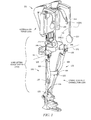
- FIG. 1 is a front view perspective drawing illustrating an example portable load lifting assist system 100 for aiding a human user comprising a lower extremity exoskeleton 120 and exoskeleton torso 160 including an exoskeleton trunk 109.
- Portable load lifting assist system 100 is wearable by a person and allows its wearer to carry a load in his/her front, and aid the person when lifting an object by significantly reducing the load on the user.
- portable load lifting assist system 100 can be used to help lift heavy loads while exerting minimal effort, such as in an example military application for soldiers going into combat with up to 130 pounds of combat gear.
- Lower extremity exoskeleton 120 in addition to other components, includes two leg supports, 101 and 102, which are configured to be coupled to person's lower limbs and configured to rest on the ground or other surface (e.g., a floor) during their stance phase.
- the leg supports 101 and 102 in addition to other components, include thigh links 103 and 104, and shank links 105 and 106.
- Two knee joints, 107 and 108 are configured to allow flexion and extension between the shank links 105 and 106 and the thigh links 103 and 104 of the leg supports 101, 102 during the corresponding leg support swing phase.
- the two knee joints 107 and 108 in some embodiments are configured to resist flexion between the shank links 105 and 106 and the thigh links 103 and 104 of the leg supports 101, 102 during the corresponding leg support stance phase.
- Exoskeleton torso 160 comprises an exoskeleton trunk 109.
- Exoskeleton trunk 109 comprises an upper body interface device 150.
- Exoskeleton trunk 109 is configurable to be coupled to the person's upper body through the upper body interface device 150.
- a person's upper body refers to any location generally above the thighs including the buttocks of the person.
- Examples of upper body interface devices 150 comprise an element or combination of elements including, without limitation, vests, belts, straps, shoulder straps, chest straps, body cast, harness, and waist belts.
- Exoskeleton trunk 109 is rotatably connectable to leg supports 101 and 102 at hip flexion-extension joints 125 and 126, allowing for the hip flexion and extension rotations of leg supports 101 and 102 about hip flexion-extension axes 151 and 152 respectively.
- Leg supports 101 and 102 are configurable to be coupled to person's lower limbs through lower limb interface straps, with the lower right interface strap 135 shown in FIG. 1 (left lower limb interface strap not shown in FIG. 1 for clarity).
- each lower limb interface strap is coupled to thigh links 103 and 104.
- lower limb interface straps are coupled to shank links 105 and 106.
- lower limb interface straps are coupled to both the shank links and thigh links.
- Each lower limb interface strap can comprise an element or combination of elements including, without limitation, straps, bars, c-shaped brackets, body cast, and elastomers.
- a person is coupled to (or wears) load lifting assist system 100 including exoskeleton torso 160 through upper body interface device 150 (a simple belt 150(a) and shoulder straps 150(b) shown in FIG. 1 ) and lower extremity exoskeleton 120 by coupling to two leg supports 101 and 102 through lower limb interface straps 135 and 136.
- lower extremity exoskeleton 120 may include two hip torque generators 145 and 146 which are configured to create torques between exoskeleton trunk 109 and leg supports 101 and 102.
- the exoskeleton torso 160 shown in FIG. 1 also includes a load lifting mechanism 221.
- the load lifting mechanism 221 in FIG. 1 has within it a winch 229 (see FIG. 3 ) which includes a reel mechanism which can reel in straps or lifting cables 222 that in one particular embodiment are nylon straps in order to lift a load connected to or contacted by end effectors 223.
- Disclosed portable load lifting systems include a power source (not shown) that can comprise a battery source, or other power sources such as fuel cell-based power sources.
- Disclosed portable load lifting assist systems such as portable load lifting assist system 100 shown in FIG. 1 are also easy for a user to put on.
- the portable load lifting assist system 100 can arrive folded in a small package, so that soldiers or other users simply stretch out a leg and step into foot beds underneath the boot. Straps can then wrap around the thighs, waist and shoulders of the soldier or other user.
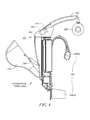
- FIG. 2 shows an example exoskeleton torso 160 including the exoskeleton trunk 109 with a load lifting mechanism 221 connected to it, according to a disclosed embodiment.
- end effector 223 is shown as a simple paddle on which a high friction material is mounted on the side opposite handle 224.
- the high friction material is used to help grip the sides of boxes and box like objects.
- One particular example of an example high friction material is "GECKO SKIN.”
- end effector 223 may generally be any item used to lift a load and may contain a force sensor 251 in the handle 224 in order to measure the load force which the human user is putting on the handle.
- Item 225 is a lifting bar which (among other things) acts as a guide for cable 222.
- the load lifting mechanism 221 (including the internal winch, straps 222, end effectors 223, and handles 224) can be a mechanism sometimes referred to as a "human power amplifier.”
- a human power amplifier An example of such a "human power amplifier” is disclosed in U.S. Patent 6,886,812 to Kazerooni.
- the load lifting mechanism 221 can also include a movable counter weight 226 which may be rotated about counter weight rotation axis 227 (see FIG. 3 ) by a counterweight actuator 228 (see FIG. 4 ).
- a counterweight actuator 228 see FIG. 4 .
- One advantageous aspect of this feature is to make the mass of the counterweight 228 include the mass of the winch 229 (including its motor, indicated by the "M" in FIG. 3 ). This can be done by routing the lifting strap or cable 222 through the path shown in FIG. 3 .
- the strap or cable 222 passes over a pulley 236 which is concentric with the counter weight rotation axis 227 and therefore the motion of the counterweight 228 has very little affect on the length (or load) of the lifting strap or cable 222.
- the motor can comprise a hydraulic motor.
- Hydraulic motor-based architectures can be highly energy efficient to help support battery powered operation of disclosed systems including the portable load lifting assist system 100 shown in FIG. 1 .
- the counterweight 226 In operation of the load lifting mechanism 221, when loads in front of the user (on the end effectors 223) are high, the counterweight 226 is moved farther aft of the user in order to balance the load (at least partially) about the hip flexion-extension axes 151 and 152. This is shown occurring in FIG. 4 .
- a controller 411 such as comprising a microprocessor (or microcomputer) 412 coupled to a force sensor 413 shown in FIG. 4 which measures the force being applied by load lifting mechanism 221 to the lifting strap or cable 222.
- the controller 411 can then send a control signal that triggers movement of the movable counter weight 226 to a position appropriate to balance the moment created about hip flexion-extension axes 151 and 152 by the counter weight 226 with the moment created by the down force on the cables 222 due to the load in front of the user.
- a control signal that triggers movement of the movable counter weight 226 to a position appropriate to balance the moment created about hip flexion-extension axes 151 and 152 by the counter weight 226 with the moment created by the down force on the cables 222 due to the load in front of the user.
- hip torque generators 145 and 146 may be greatly reduced or even eliminated because the wearer of the exoskeleton torso 160 can provide the small amount of remaining torque needed to the keep the exoskeleton trunk 109 upright.
- a movable counter weight 226 which translated linearly or swung on a linkage type mechanism in a manner that would not be a rotation about a counter weight rotation axis 227. Any mechanism which will move the counterweight farther behind (or closer to) the hip flexion-extension axes 151 and 152 will generally be able to produce the desired effect.
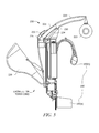
- FIG. 3 depicts a partial cross section depiction of an exemplary load lifting bar mechanism 230 associated with exoskeleton torso 160, according to a disclosed embodiment.
- the load lifting bar mechanism 230 includes a lifting bar 225, lifting bar guide 231, and cam plate 232.
- the lifting bar 225 slides over the lifting bar guide 231 in a telescopic fashion.
- the position of lifting bar 225 along the lifting bar guide 231 is determined by the cam roller 233 which is mounted on the lifting bar 225 and moves in a slot 234 on cam plate 232.
- the lifting bar guide 231 pivots on the pivot 235.
- Pulley 236 is a pulley over which the strap or cable 222 runs. When enough of the strap or cable 222 is retrieved such that the end effectors 223 are approaching the ends of the lifting bar 225, the lifting bar 225 starts to move upward and outward as the cam roller 233 moves upward in the slot 234 on cam plate 232.
- FIG. 6 shows a close up view of the rear end of the lifting bar guide 231.
- the lifting strap 222 is actually comprised of two parts, the main lifting strap 237 and the lifting strap loop 238.
- the main strap 237 and the strap loop 238 are attached (e.g., sewn or bonded) together in the regions 239 and 240.
- the pulley 236 comprises a body 241 and flanges 242.
- the strap loop 238 encounters the pulley body 241 at a point where there is still strap available between the end of the lifting bar 225 and the end effector 223. If there were no strap available, the lifting bar 225 could not extend along the lifting bar guide 231 because it would be constrained by the strap or cable 222.
- load lifting bar mechanism 230 which solely by pulling on a strap or a cable, the lifting bars will move upward and outward when the strap or cable is near the end of its travel. This allows the wearer of exoskeleton torso 160 to lift loads up to much higher heights than retracted lifting bars would allow.
- the portable load lifting assist system is not attached to a lower extremity exoskeleton 120 as described above relative to FIGS. 1-6 .
- the portable load lifting assist system can comprise only exoskeleton torso 160 which can be worn by a user analogous to a backpack.
- FIG. 7 shows a depiction of an exemplary portable load lifting assist system 700 that includes straps 710 that allows the portable load lifting assist system 700 comprising exoskeleton trunk 109 to be worn by a user like a backpack.
- the movable counter weight 226 is identified in FIG. 7 by its function "counter-balance mechanism".
- the portable load lifting system can be attached to a mobile unit.
- FIG. 8 shows an exemplary portable load lifting system 800 that comprises a cart 820 including wheels 825 that mounts an example load lifting system 840 on a movable support structure 810 (e.g., bolted or welded) that is secured to the cart 820.
- the movable support structure 810 has mobility via the cart 820.
- Portable load lifting system 800 as well as disclosed portable load lifting assist systems can be used to support a variety of applications, including military, industrial and medical applications. assist soldiers during combat.
- disclosed portable load lifting systems include simplicity of actuation and flexibility to relocate to alternate work or other areas. Unlike a fully articulated arm, disclosed embodiments can use minimal sensing and actuation capability. This reduces the cost and power requirements and improves the reliability of the design as compared to an actuated arm. Also, unlike known fixed load attachment, load lifting systems disclosed herein allow for the raising and lowering of the load. For example, a user such as a soldier using a disclosed portable lifting assist system can raise a load above his or her shoulders, as well as lower the load to the ground.
- portable load lifting systems disclosed herein have significantly enhanced flexibility in its usage. Because disclosed load lifting systems are not physically restrained to a work area, a user can operate the load lifting system inside a warehouse one minute, then head directly outside and continue to operate the load lifting system. This provides much greater utility to the user at lower cost and with lower power consumption.
Landscapes
- Engineering & Computer Science (AREA)
- Mechanical Engineering (AREA)
- Robotics (AREA)
- Manipulator (AREA)
Claims (15)
- Système de levage de charge portable (100), comprenant :une structure de support déplaçable ;un mécanisme de levage de charge (221) fixé à ladite structure de charge déplaçable comprenant un treuil (229) comportant un mécanisme d'enrouleur motorisé pour enrouler des premier et second tirants ou câbles de levage qui sont fixés à des premier et second effecteurs d'extrémité (223) ; dans lequel un élément de saisie est fourni sur la surface intérieure des premier et second effecteurs d'extrémité (223) pour saisir la charge, etdes première et seconde poignées (224) attachées à une surface extérieure desdits premier et second effecteurs d'extrémité (223), dans lequel lesdits tirants ou câbles, quand ils sont entraînés par ledit treuil (229), lèvent une charge saisie par lesdits premier et second effecteurs d'extrémité (223).
- Système selon la revendication 1, dans lequel ladite structure de support déplaçable comprend un torse d'exosquelette (160) comportant un tronc d'exosquelette (109) configuré pour être accouplé au corps supérieur d'une personne par le biais d'un dispositif d'interface de corps supérieur (150).
- Système selon la revendication 2, dans lequel ledit dispositif d'interface de corps supérieur (150) comprend un maillot, une ceinture, des sangles d'épaules, des sangles de poitrine, une coque corporelle, un harnais ou un ceinturon.
- Système selon la revendication 1, comprenant en outre un premier et un second capteur de force dans lesdites première et seconde poignées, lesdits premier et second capteurs de force (251) mesurant une force de charge qu'une personne exerce sur lesdites première et seconde poignées (224).
- Système selon la revendication 1, comprenant en outre une barre de levage (225) pour guider lesdits tirants ou câbles de levage.
- Système selon la revendication 1, comprenant en outre un contrepoids mobile (226) pouvant être mis en rotation autour d'un axe de rotation de contrepoids par un actionneur de contrepoids de telle sorte qu'une masse dudit contrepoids (226) comporte une masse dudit treuil (229).
- Système selon la revendication 6, comprenant en outre une unité de commande (411) comportant un microprocesseur ou microordinateur (412) et un capteur de force (251) qui mesure une force appliquée par ledit mécanisme de levage de charge (221) auxdits tirants ou câbles de levage,
dans lequel ladite unité de commande (411) est exploitable pour envoyer un signal de commande qui commande une position dudit contrepoids mobile (226) jusqu'à une position appropriée pour équilibrer un moment créé autour d'axes de flexion-extension de hanches par le contrepoids (226) avec un moment créé par la force descendante sur lesdits tirants ou câbles de levage devant une personne. - Système selon la revendication 1, comprenant en outre un mécanisme de barres de levage de charge (230) comprenant une première et une seconde barre de levage (225), qui exclusivement en tirant sur lesdits tirants ou câbles de levage, ladite première et ladite seconde barre de levage se déplacera vers le haut et vers l'extérieur quand ledit tirant ou câble de levage approchera de la fin de sa course.
- Système selon la revendication 8, comprenant en outre un guide de barre de levage (231), et une came (232), dans lequel ladite barre de levage (225) coulisse pardessus ledit guide de barre de levage (231) de façon télescopique, et une position de ladite barre de levage (225) le long du guide de barre de levage (231) est déterminée par un galet de came (233) qui est monté sur ladite barre de levage (225) et se déplace dans une fente sur ladite came (232), ledit guide de barre de levage (231) pivotant sur un pivot, et une poulie (236) sur laquelle lesdits tirants ou câbles de levage (222) passent, dans lequel quand une longueur suffisante desdits tirants ou câbles de levage (222) est tirée de telle sorte que lesdits premier et second effecteurs (223) s'approchent des extrémités de ladite barre de levage (225), ladite barre de levage (225) commence à se déplacer vers le haut et vers l'extérieur au fur et à mesure que le galet de came (233) remonte dans ladite fente sur ladite came (232).
- Système selon la revendication 1, dans lequel ladite structure de support déplaçable est montée sur une unité mobile (810).
- Système selon la revendication 10, dans lequel ladite unité mobile comporte des roues.
- Système selon la revendication 1, comprenant en outre un exosquelette d'extrémités inférieures (120) configuré pour être couplé aux membres inférieurs d'une personne, dans lequel ladite structure de support déplaçable comprend un torse d'exosquelette (160) comportant un tronc d'exosquelette (109) qui est configuré pour être accouplé à un corps supérieur de ladite personne par le biais d'un dispositif d'interface de corps supérieur (150) accouplé audit exosquelette d'extrémités inférieures.
- Système selon la revendication 12, dans lequel ledit exosquelette d'extrémités inférieures (120) comprend des supports de jambes (101, 102), et ledit tronc d'exosquelette (109) peut être raccordé avec faculté de rotation auxdits supports de jambes (101, 102) au niveau d'articulations de flexion-extension de hanches en vue de rotations de flexion et d'extension de hanches des supports de jambes autour d'axes de flexion-extension de hanches.
- Système selon la revendication 1, dans lequel ledit moteur comprend un moteur hydraulique.
- Système selon l'une quelconque des revendications 4, 6 à 9 ou 13, dans lequel ladite structure de support déplaçable comprend un torse d'exosquelette (160) comportant un tronc d'exosquelette (109) configuré pour être accouplé au corps supérieur d'une personne ; et comprenant en outre :un exosquelette d'extrémités inférieures (120) configuré pour être accouplé aux membres inférieurs d'une personne, dans lequel ledit tronc d'exosquelette (109) s'accouple au corps supérieur de ladite personne par le biais d'un dispositif d'interface de corps supérieur (150) qui est couplé audit exosquelette d'extrémités inférieures.
Applications Claiming Priority (2)
| Application Number | Priority Date | Filing Date | Title |
|---|---|---|---|
| US32268410P | 2010-04-09 | 2010-04-09 | |
| PCT/US2011/031956 WO2011127471A1 (fr) | 2010-04-09 | 2011-04-11 | Système portable de soulèvement de charges |
Publications (3)
| Publication Number | Publication Date |
|---|---|
| EP2556010A1 EP2556010A1 (fr) | 2013-02-13 |
| EP2556010A4 EP2556010A4 (fr) | 2014-06-25 |
| EP2556010B1 true EP2556010B1 (fr) | 2015-11-25 |
Family
ID=44763313
Family Applications (1)
| Application Number | Title | Priority Date | Filing Date |
|---|---|---|---|
| EP11766862.4A Active EP2556010B1 (fr) | 2010-04-09 | 2011-04-11 | Système portable de soulèvement de charges |
Country Status (5)
| Country | Link |
|---|---|
| US (1) | US9333644B2 (fr) |
| EP (1) | EP2556010B1 (fr) |
| JP (1) | JP6008836B2 (fr) |
| CN (1) | CN103038152A (fr) |
| WO (1) | WO2011127471A1 (fr) |
Families Citing this family (103)
| Publication number | Priority date | Publication date | Assignee | Title |
|---|---|---|---|---|
| US10124205B2 (en) | 2016-03-14 | 2018-11-13 | Tau Orthopedics, Llc | Toning garment with modular resistance unit docking platforms |
| US9656117B2 (en) * | 2009-06-19 | 2017-05-23 | Tau Orthopedics, Llc | Wearable resistance garment with power measurement |
| US9233017B2 (en) * | 2009-09-28 | 2016-01-12 | Tokyo University Of Science Foundation | Lower back assistance apparatus |
| FR2978690A1 (fr) * | 2011-08-02 | 2013-02-08 | Pierre Andre Davezac | Exosquelette de levage et de portage de charges |
| JP6169837B2 (ja) * | 2011-11-02 | 2017-07-26 | パナソニック株式会社 | 下肢動作支援装置 |
| US20130145530A1 (en) * | 2011-12-09 | 2013-06-13 | Manu Mitra | Iron man suit |
| US9095981B2 (en) | 2012-01-11 | 2015-08-04 | Garrett W. Brown | Load and torque resistant caliper exoskeleton |
| CN102805915A (zh) * | 2012-08-06 | 2012-12-05 | 陈建瑜 | 一种智能助力系统 |
| EP2931204B1 (fr) | 2012-12-11 | 2019-04-03 | Ekso Bionics, Inc. | Exosquelette reconfigurable |
| CN103006416B (zh) * | 2013-01-04 | 2014-08-20 | 哈尔滨工程大学 | 机械式下肢康复机器人助行装置 |
| WO2014159608A1 (fr) * | 2013-03-14 | 2014-10-02 | Ekso Bionics, Inc. | Emplacements d'articulation de la hanche non anthropomorphiques pour des exosquelettes |
| CN103284819B (zh) * | 2013-04-24 | 2015-08-19 | 西南交通大学 | 一种助力型外骨骼用前抬式可调节背负系统 |
| JP6284319B2 (ja) * | 2013-08-30 | 2018-02-28 | 三菱重工業株式会社 | パワーアシストスーツ |
| JP6284318B2 (ja) * | 2013-08-30 | 2018-02-28 | 三菱重工業株式会社 | パワーアシストスーツ |
| KR101500525B1 (ko) * | 2013-10-16 | 2015-03-09 | 대우조선해양 주식회사 | 산업용 착용로봇의 접이식 작업유닛 |
| ITFR20130013A1 (it) * | 2013-11-25 | 2015-05-26 | Marco Ceccarelli | Dispositivo ad esoscheletro per assistenza alla locomozione umana. |
| JP5902664B2 (ja) * | 2013-12-25 | 2016-04-13 | ファナック株式会社 | 保護部材を有する人協調型産業用ロボット |
| FR3016821B1 (fr) * | 2014-01-29 | 2019-08-02 | Robotiques 3 Dimensions | Exosquelette a port frontal et procede d'utilisation d'un tel exosquelette. |
| JP6148192B2 (ja) * | 2014-03-20 | 2017-06-14 | 株式会社クボタ | アシストスーツ |
| JP6153881B2 (ja) * | 2014-03-20 | 2017-06-28 | 株式会社クボタ | アシストスーツ |
| JP6184355B2 (ja) * | 2014-03-20 | 2017-08-23 | 株式会社クボタ | アシストスーツ |
| US10213357B2 (en) * | 2014-03-21 | 2019-02-26 | Ekso Bionics, Inc. | Ambulatory exoskeleton and method of relocating exoskeleton |
| EP3151804B1 (fr) * | 2014-06-04 | 2023-01-11 | Ekso Bionics, Inc. | Exosquelette et procédé d'accroissement de la flexibilité d'une articulation de hanche d'un exosquelette |
| EP3157471B1 (fr) * | 2014-06-18 | 2021-11-24 | Mawashi Protective Clothing Inc. | Exosquelette et son procédé d'utilisation |
| CN104013514B (zh) * | 2014-06-19 | 2017-02-15 | 中国北方车辆研究所 | 一种液压驱动的可穿戴式人体助力行走机器人 |
| US10561568B1 (en) * | 2014-06-19 | 2020-02-18 | Lockheed Martin Corporation | Exoskeleton system providing for a load transfer when a user is standing and kneeling |
| KR102250235B1 (ko) * | 2014-07-17 | 2021-05-10 | 삼성전자주식회사 | 고정 모듈 및 이를 포함하는 운동 보조 장치 |
| US20160158593A1 (en) * | 2014-12-04 | 2016-06-09 | Florida Institute for Human and Machine Cognition | Exoskeleton-Based Exercise and Training Device |
| JP2016130160A (ja) * | 2015-01-14 | 2016-07-21 | 株式会社クボタ | アシストスーツ |
| JP6504823B2 (ja) * | 2015-01-14 | 2019-04-24 | 株式会社クボタ | アシストスーツ |
| WO2016113954A1 (fr) * | 2015-01-14 | 2016-07-21 | 株式会社クボタ | Combinaison d'assistance |
| JP2016129917A (ja) * | 2015-01-14 | 2016-07-21 | 株式会社クボタ | アシストスーツ |
| JP6548394B2 (ja) * | 2015-01-14 | 2019-07-24 | 株式会社クボタ | アシストスーツ |
| CN104669249B (zh) * | 2015-02-01 | 2016-05-04 | 襄阳新火炬科技有限公司 | 一种液压驱动式机器人 |
| EP3064822B1 (fr) * | 2015-03-02 | 2018-05-30 | Easyrig AB | Plate-forme de caméra |
| US10390973B2 (en) | 2015-05-11 | 2019-08-27 | The Hong Kong Polytechnic University | Interactive exoskeleton robotic knee system |
| EP4218685A3 (fr) * | 2015-05-18 | 2023-09-13 | The Regents of the University of California | Procédé et appareil pour exosquelette de support de bras humain |
| US10548800B1 (en) | 2015-06-18 | 2020-02-04 | Lockheed Martin Corporation | Exoskeleton pelvic link having hip joint and inguinal joint |
| US10518404B2 (en) | 2015-07-17 | 2019-12-31 | Lockheed Martin Corporation | Variable force exoskeleton hip joint |
| US10195736B2 (en) * | 2015-07-17 | 2019-02-05 | Lockheed Martin Corporation | Variable force exoskeleton hip joint |
| CN105105896B (zh) * | 2015-09-17 | 2016-11-30 | 武汉大学 | 用于穿戴式下肢外骨骼机器人与人体腰部固定的调节装置 |
| WO2017075462A1 (fr) | 2015-10-30 | 2017-05-04 | Ekso Bionics, Inc. | Dispostifs à exosquelette humain pour supporter et utiliser des outils lourds |
| JP6643874B2 (ja) * | 2015-11-20 | 2020-02-12 | 株式会社クボタ | アシストスーツ |
| JP6754563B2 (ja) * | 2015-11-20 | 2020-09-16 | 株式会社クボタ | アシストスーツ |
| JP6541553B2 (ja) * | 2015-11-20 | 2019-07-10 | 株式会社クボタ | アシストスーツ |
| EP3378606B1 (fr) | 2015-11-20 | 2023-08-02 | Kubota Corporation | Combinaison d'assistance |
| JP6541552B2 (ja) * | 2015-11-20 | 2019-07-10 | 株式会社クボタ | アシストスーツ |
| US10912346B1 (en) | 2015-11-24 | 2021-02-09 | Lockheed Martin Corporation | Exoskeleton boot and lower link |
| US10124484B1 (en) | 2015-12-08 | 2018-11-13 | Lockheed Martin Corporation | Load-bearing powered exoskeleton using electromyographic control |
| US20190344432A1 (en) | 2015-12-24 | 2019-11-14 | Safran Electronics & Defense | Modular exoskeleton structure that provides force assistance to the user |
| FR3046038B1 (fr) * | 2015-12-24 | 2017-12-22 | Sagem Defense Securite | Module de support de sac a dos pour une structure modulaire d'exosquelette |
| FR3046051B1 (fr) * | 2015-12-24 | 2020-11-13 | Sagem Defense Securite | Module de dos pour une structure d'exosquelette |
| JP6671179B2 (ja) * | 2016-01-15 | 2020-03-25 | 株式会社クボタ | アシスト器具 |
| KR102276029B1 (ko) | 2016-01-15 | 2021-07-13 | 가부시끼 가이샤 구보다 | 어시스트 기구 |
| JP6671180B2 (ja) * | 2016-01-15 | 2020-03-25 | 株式会社クボタ | アシスト器具 |
| CN105853145B (zh) * | 2016-04-12 | 2020-10-09 | 合肥工业大学 | 一种可实现履步功能的腿部机械机构 |
| US11209121B2 (en) * | 2016-04-26 | 2021-12-28 | The Boeing Company | Lifting support device and method of controlling operation |
| JP6566912B2 (ja) * | 2016-06-28 | 2019-08-28 | 株式会社クボタ | アシストスーツ |
| JP2018002333A (ja) * | 2016-06-28 | 2018-01-11 | 株式会社クボタ | アシストスーツ |
| CN106346452B (zh) * | 2016-11-02 | 2017-06-23 | 广州初曲科技有限公司 | 一种提供腰背部力量辅助的气电联动式外骨骼动力装备 |
| CN109937123A (zh) * | 2016-12-22 | 2019-06-25 | 株式会社久保田 | 辅助设备 |
| FR3061445B1 (fr) * | 2016-12-29 | 2019-05-24 | Safran Electronics & Defense | Dispositif de liaison pour structure d'exosquelette facilitant le portage de charges pendant la marche ou la course |
| CN106821689B (zh) * | 2017-01-19 | 2023-07-04 | 武汉云云天下信息科技有限公司 | 一种可穿戴式人体外骨骼机器人 |
| CN106628806A (zh) * | 2017-02-28 | 2017-05-10 | 深圳龙海特机器人科技有限公司 | 双开穿戴式辅助搬运装置 |
| JP2018149624A (ja) * | 2017-03-13 | 2018-09-27 | パナソニック株式会社 | 動作支援装置 |
| JP6783171B2 (ja) * | 2017-03-23 | 2020-11-11 | 株式会社クボタ | アシスト器具 |
| JP6742274B2 (ja) * | 2017-05-18 | 2020-08-19 | 株式会社クボタ | アシストスーツ |
| JP2017149585A (ja) * | 2017-05-30 | 2017-08-31 | 株式会社クボタ | アシストスーツ |
| WO2019004345A1 (fr) * | 2017-06-29 | 2019-01-03 | 株式会社クボタ | Pièce de main destinée à contenir des bagages, et instrument d'assistance |
| CA3073504A1 (fr) | 2017-08-30 | 2019-03-07 | Lockheed Martin Corporation | Selection de capteur automatique |
| CN110253540B (zh) * | 2017-09-07 | 2022-05-17 | 重庆市牛迪科技发展有限公司 | 一种外骨骼 |
| US11000439B2 (en) * | 2017-09-28 | 2021-05-11 | Ossur Iceland Ehf | Body interface |
| CN107569367B (zh) * | 2017-10-18 | 2021-09-17 | 房倩玉 | 一种下肢康复训练设备 |
| US10835444B2 (en) * | 2017-11-13 | 2020-11-17 | Free Bionics Taiwan Inc. | Shoe assembly for a walking assist device |
| DE102018103300A1 (de) * | 2018-02-14 | 2019-08-14 | Noonee Ag | Tragbare Sitzhaltungshilfevorrichtung |
| CN109081038A (zh) * | 2018-09-18 | 2018-12-25 | 上海工程技术大学 | 一种穿戴式省力装置 |
| USD947388S1 (en) * | 2018-12-10 | 2022-03-29 | Jtekt Corporation | Motion assisting device |
| JP6758364B2 (ja) * | 2018-12-25 | 2020-09-23 | 株式会社クボタ | アシストスーツ |
| US10765911B1 (en) | 2019-03-01 | 2020-09-08 | Dustin Hamoy | Core exercise assembly |
| JP6749443B2 (ja) * | 2019-03-07 | 2020-09-02 | 株式会社クボタ | アシストスーツ |
| JP6756002B2 (ja) * | 2019-05-07 | 2020-09-16 | 株式会社クボタ | アシストスーツ |
| JP7240264B2 (ja) | 2019-06-12 | 2023-03-15 | Kyb株式会社 | 電動パワーステアリング装置 |
| WO2020255676A1 (fr) * | 2019-06-18 | 2020-12-24 | 株式会社キトー | Dispositif de commande de puissance et procédé de commande de puissance |
| CN110575366B (zh) * | 2019-09-19 | 2022-01-18 | 哈尔滨工业大学 | 一种主被动结合的下肢助力外骨骼机器人 |
| CN111285280B (zh) * | 2020-02-02 | 2021-08-31 | 广西电网有限责任公司北海供电局 | 一种背负式电力高空作业传递装置 |
| RU198903U1 (ru) * | 2020-02-26 | 2020-07-31 | ООО "Экзомед" | Экзоскелет |
| WO2021188950A1 (fr) | 2020-03-19 | 2021-09-23 | U.S. Bionics Inc. (DBA: suitX) | Articulation d'épaule à centre distant pour exosquelette de support d'épaule |
| JP7505266B2 (ja) * | 2020-05-25 | 2024-06-25 | 株式会社ジェイテクト | アシスト装置 |
| RU202647U1 (ru) * | 2020-06-11 | 2021-03-01 | Общество с ограниченной ответственностью "Экзомед" | Устройство для облегчения перетаскивания грузов |
| EP4015156A1 (fr) * | 2020-12-15 | 2022-06-22 | Auxivo AG | Dispositif de support de charge et son utilisation |
| CN112936232B (zh) * | 2021-04-08 | 2022-10-28 | 中国科学技术大学 | 一种辅助潜水的髋关节外骨骼机器人系统 |
| EP4079460A1 (fr) * | 2021-04-22 | 2022-10-26 | Hilti Aktiengesellschaft | Système, ensemble et module électronique permettant d'équilibrer une force pondérale d'un objet |
| FR3125453A1 (fr) * | 2021-07-26 | 2023-01-27 | Hublex | Dispositif d’assistance au port manuel de charges |
| CN113894771A (zh) * | 2021-08-27 | 2022-01-07 | 北京机械设备研究所 | 一种主动拉带式上肢助力外骨骼 |
| WO2023086541A1 (fr) * | 2021-11-12 | 2023-05-19 | Hamon Richard A | Système monte-échelle et chariot |
| US20230203888A1 (en) * | 2021-12-29 | 2023-06-29 | MulePro Industries LLC | Building Ladder Hoist |
| DE102022100204A1 (de) * | 2022-01-05 | 2023-07-06 | J.Schmalz Gmbh | Anziehbare Hilfsvorrichtung mit gelenkiger Anbindung der oberen Körperanbindung |
| DE102022100203A1 (de) * | 2022-01-05 | 2023-07-06 | J.Schmalz Gmbh | Anziehbare Hilfsvorrichtung mit gelenkiger Anbindung der unteren Körperanbindung |
| CN114643571B (zh) * | 2022-03-14 | 2023-07-21 | 南京赤研科技有限公司 | 一种全自由度上肢外骨骼装置 |
| CN114932536B (zh) * | 2022-05-31 | 2023-07-28 | 山东大学 | 可行走的主动式机械装置 |
| CN114833804B (zh) * | 2022-06-13 | 2024-09-13 | 山东瑞曼智能装备有限公司 | 一种适用于多场景的有源助力装置及方法 |
| CN115302493A (zh) * | 2022-07-25 | 2022-11-08 | 重庆理工大学 | 摩擦阻尼驱动器及外骨骼 |
| WO2024039310A1 (fr) * | 2022-08-16 | 2024-02-22 | Interact Medikal Teknolojileri Anonim Sirketi | Exosquelette passif réglable |
Family Cites Families (51)
| Publication number | Priority date | Publication date | Assignee | Title |
|---|---|---|---|---|
| US2010482A (en) * | 1934-05-26 | 1935-08-06 | Florence M Henn | Walking motion |
| FR2249997B1 (fr) * | 1973-10-31 | 1979-03-09 | Pomeret Jean Claude | |
| AT351794B (de) | 1977-11-10 | 1979-08-10 | Philips Nv | Schlingfederkupplung |
| US5016869A (en) * | 1989-07-05 | 1991-05-21 | Applied Motion | Human bipedal locomotion device |
| JPH03105191U (fr) * | 1990-02-15 | 1991-10-31 | ||
| US5020790A (en) * | 1990-10-23 | 1991-06-04 | Board Of Supervisors Of Louisiana State University And Agricultural And Mechanical College | Powered gait orthosis |
| JP3024978U (ja) * | 1995-10-13 | 1996-06-07 | 吉村 敏正 | 背負い式荷物持ち上げ装置 |
| US5865426A (en) * | 1996-03-27 | 1999-02-02 | Kazerooni; Homayoon | Human power amplifier for vertical maneuvers |
| US5993404A (en) | 1998-06-16 | 1999-11-30 | Mc Niel; Frank T. | Walking brace |
| US6386513B1 (en) | 1999-05-13 | 2002-05-14 | Hamayoon Kazerooni | Human power amplifier for lifting load including apparatus for preventing slack in lifting cable |
| US7153242B2 (en) | 2001-05-24 | 2006-12-26 | Amit Goffer | Gait-locomotor apparatus |
| JP2003104682A (ja) * | 2001-09-30 | 2003-04-09 | Kosho Unyu Kk | 荷物移動補助具 |
| US20030073552A1 (en) | 2001-10-11 | 2003-04-17 | Knight Michael W. | Biosensory ergonomic chair |
| US20030115954A1 (en) | 2001-12-07 | 2003-06-26 | Vladimir Zemlyakov | Upper extremity exoskeleton structure and method |
| US20030109817A1 (en) | 2001-12-11 | 2003-06-12 | Shimon Berl | Supplementary knee support brace |
| US6913583B2 (en) | 2003-06-19 | 2005-07-05 | Creations By B J H, Llc | Orthopedic device allows kneeling without contacting knee |
| US7163518B1 (en) | 2003-10-20 | 2007-01-16 | Rgpartnership Llp | Walking leg support |
| US7628766B1 (en) | 2003-10-29 | 2009-12-08 | The Regents Of The University Of California | Lower extremity enhancer |
| US20050137717A1 (en) | 2003-12-18 | 2005-06-23 | Finn Gramnas | Prosthetic foot with rocker member |
| US7571839B2 (en) | 2004-05-19 | 2009-08-11 | Hrl Laboratories, Llc | Passive exoskeleton |
| US7429253B2 (en) * | 2004-09-21 | 2008-09-30 | Honda Motor Co., Ltd. | Walking assistance system |
| CA2601220C (fr) | 2005-01-18 | 2014-03-18 | The Regents Of The University Of California | Exosquelette des membres inferieurs |
| US20070123997A1 (en) | 2005-03-31 | 2007-05-31 | Massachusetts Institute Of Technology | Exoskeletons for running and walking |
| PL1874239T3 (pl) | 2005-04-13 | 2014-10-31 | Univ California | Pół-wspomagany egzoszkielet kończyny dolnej |
| AU2007223733B2 (en) | 2006-03-09 | 2013-01-10 | The Regents Of The University Of California | Power generating leg |
| US8849457B2 (en) * | 2006-07-17 | 2014-09-30 | Raytheon Company | Contact displacement actuator system |
| WO2008129096A1 (fr) | 2007-04-23 | 2008-10-30 | Golden Crab, S.L. | Exosquelette de sécurité et de contrôle pour la pratique du ski |
| JP5152852B2 (ja) | 2007-06-07 | 2013-02-27 | 学校法人東京理科大学 | 腰部補助装置 |
| WO2010019300A1 (fr) | 2008-05-20 | 2010-02-18 | University Of California At Berkeley | Dispositif et méthode de réduction de la consommation d'oxygène d'une personne pendant une marche régulière au moyen d'un exosquelette porteur de charge |
| US8945028B2 (en) | 2008-05-20 | 2015-02-03 | Ekso Bionics, Inc. | Device and method for decreasing energy consumption of a person by use of a lower extremity exoskeleton |
| AU2009257402B2 (en) | 2008-06-11 | 2013-08-29 | The Regents Of The University Of California | External walking assist device for those with lower leg injuries |
| US9351855B2 (en) | 2008-06-16 | 2016-05-31 | Ekso Bionics, Inc. | Powered lower extremity orthotic and method of operation |
| WO2010005473A1 (fr) | 2008-06-16 | 2010-01-14 | Berkeley Bionics | Prothèse transfémorale semi-actionnée de genou |
| US8801641B2 (en) | 2008-07-23 | 2014-08-12 | Ekso Bionics, Inc. | Exoskeleton and method for controlling a swing leg of the exoskeleton |
| US8516918B2 (en) * | 2008-08-28 | 2013-08-27 | Raytheon Company | Biomimetic mechanical joint |
| EP2346467B1 (fr) | 2008-09-24 | 2019-07-17 | Ekso Bionics, Inc. | Systèmes d'actionnement de hanche et de genou pour dispositifs orthétiques de membres inférieurs |
| JP5235838B2 (ja) | 2008-11-06 | 2013-07-10 | 本田技研工業株式会社 | 歩行補助装置 |
| US8672865B2 (en) | 2008-11-26 | 2014-03-18 | Toad Medical Corporation | Weight-bearing lower extremity brace |
| AU2009341585B2 (en) | 2008-12-18 | 2015-06-18 | Ekso Bionics, Inc. | Wearable material handling system |
| KR101073525B1 (ko) | 2009-01-12 | 2011-10-17 | 한양대학교 산학협력단 | 하지근력지원용 착용형 로봇 |
| CA2769975A1 (fr) | 2009-07-01 | 2011-01-06 | Rex Bionics Limited | Systeme de commande d'aide a la mobilite |
| WO2011123928A1 (fr) | 2010-04-07 | 2011-10-13 | B-Temia Inc. | Dispositif de répartition de charge pour des articulations humaines |
| WO2011127421A1 (fr) | 2010-04-09 | 2011-10-13 | Berkeley Bionics | Système de gestion de charge d'exosquelette et son procédé d'utilisation |
| EP2616115B1 (fr) | 2010-09-17 | 2016-08-24 | Ekso Bionics | Utilisation d'une interface homme-machine pour un exosquelette humain |
| WO2012044621A1 (fr) | 2010-09-27 | 2012-04-05 | Vanderbilt University | Dispositif d'aide à la mobilité |
| US9801772B2 (en) | 2010-10-06 | 2017-10-31 | Ekso Bionics, Inc. | Human machine interfaces for lower extremity orthotics |
| US9060883B2 (en) | 2011-03-11 | 2015-06-23 | Iwalk, Inc. | Biomimetic joint actuators |
| US9719633B2 (en) | 2011-05-06 | 2017-08-01 | Garrett W. Brown | Exoskeleton arm interface |
| US9682005B2 (en) | 2012-02-24 | 2017-06-20 | Massachusetts Institute Of Technology | Elastic element exoskeleton and method of using same |
| US20140046234A1 (en) | 2012-08-09 | 2014-02-13 | Egas Jose-Joaquim DeSousa | Dynamic Load Bearing Shock Absorbing Exoskeletal Knee Brace |
| US9662261B2 (en) | 2013-01-16 | 2017-05-30 | Ekso Bionics, Inc. | Fail-safe system for exoskeleton joints |
-
2011
- 2011-04-11 US US13/084,265 patent/US9333644B2/en not_active Expired - Fee Related
- 2011-04-11 CN CN2011800283325A patent/CN103038152A/zh active Pending
- 2011-04-11 EP EP11766862.4A patent/EP2556010B1/fr active Active
- 2011-04-11 JP JP2013504019A patent/JP6008836B2/ja not_active Expired - Fee Related
- 2011-04-11 WO PCT/US2011/031956 patent/WO2011127471A1/fr active Application Filing
Also Published As
| Publication number | Publication date |
|---|---|
| CN103038152A (zh) | 2013-04-10 |
| WO2011127471A1 (fr) | 2011-10-13 |
| US20110264014A1 (en) | 2011-10-27 |
| EP2556010A1 (fr) | 2013-02-13 |
| JP2013531593A (ja) | 2013-08-08 |
| EP2556010A4 (fr) | 2014-06-25 |
| JP6008836B2 (ja) | 2016-10-19 |
| US9333644B2 (en) | 2016-05-10 |
Similar Documents
| Publication | Publication Date | Title |
|---|---|---|
| EP2556010B1 (fr) | Système portable de soulèvement de charges | |
| CA2796088C (fr) | Systeme de gestion de charge d'exosquelette et son procede d'utilisation | |
| US8968222B2 (en) | Wearable material handling system | |
| JP5909063B2 (ja) | パワーアシストロボット装置 | |
| JP5420405B2 (ja) | ロボット骨組、外骨格構造体、装着式のロボットシステム、人体と協調して装着式のロボット骨組を同時に動かす方法、装着式の人間の外骨格を人体の動きと協調して動かせるようにする方法 | |
| CN102859609B (zh) | 一种防护装置及其操作方法 | |
| JP2013531593A5 (fr) | ||
| CN110328657A (zh) | 一种柔性外骨骼助力机器人 | |
| JP2009543706A5 (fr) | ||
| CN112025681B (zh) | 电动腰部辅助外骨骼 | |
| KR102478064B1 (ko) | 착용식 로봇 및 착용식 로봇의 제어 방법 | |
| CN106903674B (zh) | 一种可穿戴的上肢外骨骼助力装置 | |
| KR20240029875A (ko) | 작업자용 보조기 | |
| CN109864863A (zh) | 一种具有搂抱托举仿生功能双升降臂人工智能移位机 | |
| KR20190129726A (ko) | 관절 보조력 발생 기기 | |
| WO2023119400A1 (fr) | Dispositif d'assistance et ceinture d'assistance | |
| CN116810762A (zh) | 基于折纸机构的仿生脊椎腰部搬运外骨骼及其控制方法 |
Legal Events
| Date | Code | Title | Description |
|---|---|---|---|
| PUAI | Public reference made under article 153(3) epc to a published international application that has entered the european phase |
Free format text: ORIGINAL CODE: 0009012 |
|
| 17P | Request for examination filed |
Effective date: 20121109 |
|
| AK | Designated contracting states |
Kind code of ref document: A1 Designated state(s): AL AT BE BG CH CY CZ DE DK EE ES FI FR GB GR HR HU IE IS IT LI LT LU LV MC MK MT NL NO PL PT RO RS SE SI SK SM TR |
|
| DAX | Request for extension of the european patent (deleted) | ||
| A4 | Supplementary search report drawn up and despatched |
Effective date: 20140527 |
|
| RIC1 | Information provided on ipc code assigned before grant |
Ipc: B66D 3/18 20060101AFI20140521BHEP |
|
| GRAP | Despatch of communication of intention to grant a patent |
Free format text: ORIGINAL CODE: EPIDOSNIGR1 |
|
| INTG | Intention to grant announced |
Effective date: 20150610 |
|
| GRAS | Grant fee paid |
Free format text: ORIGINAL CODE: EPIDOSNIGR3 |
|
| GRAA | (expected) grant |
Free format text: ORIGINAL CODE: 0009210 |
|
| AK | Designated contracting states |
Kind code of ref document: B1 Designated state(s): AL AT BE BG CH CY CZ DE DK EE ES FI FR GB GR HR HU IE IS IT LI LT LU LV MC MK MT NL NO PL PT RO RS SE SI SK SM TR |
|
| REG | Reference to a national code |
Ref country code: GB Ref legal event code: FG4D |
|
| REG | Reference to a national code |
Ref country code: CH Ref legal event code: EP |
|
| REG | Reference to a national code |
Ref country code: AT Ref legal event code: REF Ref document number: 762481 Country of ref document: AT Kind code of ref document: T Effective date: 20151215 |
|
| REG | Reference to a national code |
Ref country code: IE Ref legal event code: FG4D |
|
| REG | Reference to a national code |
Ref country code: DE Ref legal event code: R096 Ref document number: 602011021664 Country of ref document: DE |
|
| REG | Reference to a national code |
Ref country code: LT Ref legal event code: MG4D |
|
| REG | Reference to a national code |
Ref country code: NL Ref legal event code: MP Effective date: 20160225 |
|
| REG | Reference to a national code |
Ref country code: AT Ref legal event code: MK05 Ref document number: 762481 Country of ref document: AT Kind code of ref document: T Effective date: 20151125 |
|
| PG25 | Lapsed in a contracting state [announced via postgrant information from national office to epo] |
Ref country code: ES Free format text: LAPSE BECAUSE OF FAILURE TO SUBMIT A TRANSLATION OF THE DESCRIPTION OR TO PAY THE FEE WITHIN THE PRESCRIBED TIME-LIMIT Effective date: 20151125 Ref country code: IS Free format text: LAPSE BECAUSE OF FAILURE TO SUBMIT A TRANSLATION OF THE DESCRIPTION OR TO PAY THE FEE WITHIN THE PRESCRIBED TIME-LIMIT Effective date: 20160325 Ref country code: NO Free format text: LAPSE BECAUSE OF FAILURE TO SUBMIT A TRANSLATION OF THE DESCRIPTION OR TO PAY THE FEE WITHIN THE PRESCRIBED TIME-LIMIT Effective date: 20160225 Ref country code: NL Free format text: LAPSE BECAUSE OF FAILURE TO SUBMIT A TRANSLATION OF THE DESCRIPTION OR TO PAY THE FEE WITHIN THE PRESCRIBED TIME-LIMIT Effective date: 20151125 Ref country code: LT Free format text: LAPSE BECAUSE OF FAILURE TO SUBMIT A TRANSLATION OF THE DESCRIPTION OR TO PAY THE FEE WITHIN THE PRESCRIBED TIME-LIMIT Effective date: 20151125 Ref country code: HR Free format text: LAPSE BECAUSE OF FAILURE TO SUBMIT A TRANSLATION OF THE DESCRIPTION OR TO PAY THE FEE WITHIN THE PRESCRIBED TIME-LIMIT Effective date: 20151125 |
|
| PG25 | Lapsed in a contracting state [announced via postgrant information from national office to epo] |
Ref country code: RS Free format text: LAPSE BECAUSE OF FAILURE TO SUBMIT A TRANSLATION OF THE DESCRIPTION OR TO PAY THE FEE WITHIN THE PRESCRIBED TIME-LIMIT Effective date: 20151125 Ref country code: FI Free format text: LAPSE BECAUSE OF FAILURE TO SUBMIT A TRANSLATION OF THE DESCRIPTION OR TO PAY THE FEE WITHIN THE PRESCRIBED TIME-LIMIT Effective date: 20151125 Ref country code: PL Free format text: LAPSE BECAUSE OF FAILURE TO SUBMIT A TRANSLATION OF THE DESCRIPTION OR TO PAY THE FEE WITHIN THE PRESCRIBED TIME-LIMIT Effective date: 20151125 Ref country code: GR Free format text: LAPSE BECAUSE OF FAILURE TO SUBMIT A TRANSLATION OF THE DESCRIPTION OR TO PAY THE FEE WITHIN THE PRESCRIBED TIME-LIMIT Effective date: 20160226 Ref country code: PT Free format text: LAPSE BECAUSE OF FAILURE TO SUBMIT A TRANSLATION OF THE DESCRIPTION OR TO PAY THE FEE WITHIN THE PRESCRIBED TIME-LIMIT Effective date: 20160325 Ref country code: AT Free format text: LAPSE BECAUSE OF FAILURE TO SUBMIT A TRANSLATION OF THE DESCRIPTION OR TO PAY THE FEE WITHIN THE PRESCRIBED TIME-LIMIT Effective date: 20151125 Ref country code: LV Free format text: LAPSE BECAUSE OF FAILURE TO SUBMIT A TRANSLATION OF THE DESCRIPTION OR TO PAY THE FEE WITHIN THE PRESCRIBED TIME-LIMIT Effective date: 20151125 Ref country code: SE Free format text: LAPSE BECAUSE OF FAILURE TO SUBMIT A TRANSLATION OF THE DESCRIPTION OR TO PAY THE FEE WITHIN THE PRESCRIBED TIME-LIMIT Effective date: 20151125 |
|
| PG25 | Lapsed in a contracting state [announced via postgrant information from national office to epo] |
Ref country code: IT Free format text: LAPSE BECAUSE OF FAILURE TO SUBMIT A TRANSLATION OF THE DESCRIPTION OR TO PAY THE FEE WITHIN THE PRESCRIBED TIME-LIMIT Effective date: 20151125 Ref country code: CZ Free format text: LAPSE BECAUSE OF FAILURE TO SUBMIT A TRANSLATION OF THE DESCRIPTION OR TO PAY THE FEE WITHIN THE PRESCRIBED TIME-LIMIT Effective date: 20151125 |
|
| REG | Reference to a national code |
Ref country code: DE Ref legal event code: R097 Ref document number: 602011021664 Country of ref document: DE |
|
| PG25 | Lapsed in a contracting state [announced via postgrant information from national office to epo] |
Ref country code: SK Free format text: LAPSE BECAUSE OF FAILURE TO SUBMIT A TRANSLATION OF THE DESCRIPTION OR TO PAY THE FEE WITHIN THE PRESCRIBED TIME-LIMIT Effective date: 20151125 Ref country code: EE Free format text: LAPSE BECAUSE OF FAILURE TO SUBMIT A TRANSLATION OF THE DESCRIPTION OR TO PAY THE FEE WITHIN THE PRESCRIBED TIME-LIMIT Effective date: 20151125 Ref country code: RO Free format text: LAPSE BECAUSE OF FAILURE TO SUBMIT A TRANSLATION OF THE DESCRIPTION OR TO PAY THE FEE WITHIN THE PRESCRIBED TIME-LIMIT Effective date: 20151125 Ref country code: DK Free format text: LAPSE BECAUSE OF FAILURE TO SUBMIT A TRANSLATION OF THE DESCRIPTION OR TO PAY THE FEE WITHIN THE PRESCRIBED TIME-LIMIT Effective date: 20151125 Ref country code: BE Free format text: LAPSE BECAUSE OF NON-PAYMENT OF DUE FEES Effective date: 20160430 Ref country code: SM Free format text: LAPSE BECAUSE OF FAILURE TO SUBMIT A TRANSLATION OF THE DESCRIPTION OR TO PAY THE FEE WITHIN THE PRESCRIBED TIME-LIMIT Effective date: 20151125 |
|
| PLBE | No opposition filed within time limit |
Free format text: ORIGINAL CODE: 0009261 |
|
| STAA | Information on the status of an ep patent application or granted ep patent |
Free format text: STATUS: NO OPPOSITION FILED WITHIN TIME LIMIT |
|
| REG | Reference to a national code |
Ref country code: DE Ref legal event code: R119 Ref document number: 602011021664 Country of ref document: DE |
|
| 26N | No opposition filed |
Effective date: 20160826 |
|
| PG25 | Lapsed in a contracting state [announced via postgrant information from national office to epo] |
Ref country code: SI Free format text: LAPSE BECAUSE OF FAILURE TO SUBMIT A TRANSLATION OF THE DESCRIPTION OR TO PAY THE FEE WITHIN THE PRESCRIBED TIME-LIMIT Effective date: 20151125 |
|
| REG | Reference to a national code |
Ref country code: CH Ref legal event code: PL |
|
| PG25 | Lapsed in a contracting state [announced via postgrant information from national office to epo] |
Ref country code: LU Free format text: LAPSE BECAUSE OF FAILURE TO SUBMIT A TRANSLATION OF THE DESCRIPTION OR TO PAY THE FEE WITHIN THE PRESCRIBED TIME-LIMIT Effective date: 20160411 Ref country code: BE Free format text: LAPSE BECAUSE OF FAILURE TO SUBMIT A TRANSLATION OF THE DESCRIPTION OR TO PAY THE FEE WITHIN THE PRESCRIBED TIME-LIMIT Effective date: 20151125 |
|
| REG | Reference to a national code |
Ref country code: IE Ref legal event code: MM4A |
|
| REG | Reference to a national code |
Ref country code: FR Ref legal event code: ST Effective date: 20161230 |
|
| PG25 | Lapsed in a contracting state [announced via postgrant information from national office to epo] |
Ref country code: CH Free format text: LAPSE BECAUSE OF NON-PAYMENT OF DUE FEES Effective date: 20160430 Ref country code: DE Free format text: LAPSE BECAUSE OF NON-PAYMENT OF DUE FEES Effective date: 20161101 Ref country code: FR Free format text: LAPSE BECAUSE OF NON-PAYMENT OF DUE FEES Effective date: 20160502 Ref country code: LI Free format text: LAPSE BECAUSE OF NON-PAYMENT OF DUE FEES Effective date: 20160430 |
|
| PG25 | Lapsed in a contracting state [announced via postgrant information from national office to epo] |
Ref country code: IE Free format text: LAPSE BECAUSE OF NON-PAYMENT OF DUE FEES Effective date: 20160411 |
|
| PG25 | Lapsed in a contracting state [announced via postgrant information from national office to epo] |
Ref country code: CY Free format text: LAPSE BECAUSE OF FAILURE TO SUBMIT A TRANSLATION OF THE DESCRIPTION OR TO PAY THE FEE WITHIN THE PRESCRIBED TIME-LIMIT Effective date: 20151125 Ref country code: HU Free format text: LAPSE BECAUSE OF FAILURE TO SUBMIT A TRANSLATION OF THE DESCRIPTION OR TO PAY THE FEE WITHIN THE PRESCRIBED TIME-LIMIT; INVALID AB INITIO Effective date: 20110411 |
|
| PG25 | Lapsed in a contracting state [announced via postgrant information from national office to epo] |
Ref country code: MT Free format text: LAPSE BECAUSE OF NON-PAYMENT OF DUE FEES Effective date: 20160430 Ref country code: MC Free format text: LAPSE BECAUSE OF FAILURE TO SUBMIT A TRANSLATION OF THE DESCRIPTION OR TO PAY THE FEE WITHIN THE PRESCRIBED TIME-LIMIT Effective date: 20151125 Ref country code: MK Free format text: LAPSE BECAUSE OF FAILURE TO SUBMIT A TRANSLATION OF THE DESCRIPTION OR TO PAY THE FEE WITHIN THE PRESCRIBED TIME-LIMIT Effective date: 20151125 |
|
| PG25 | Lapsed in a contracting state [announced via postgrant information from national office to epo] |
Ref country code: BG Free format text: LAPSE BECAUSE OF FAILURE TO SUBMIT A TRANSLATION OF THE DESCRIPTION OR TO PAY THE FEE WITHIN THE PRESCRIBED TIME-LIMIT Effective date: 20151125 |
|
| PG25 | Lapsed in a contracting state [announced via postgrant information from national office to epo] |
Ref country code: AL Free format text: LAPSE BECAUSE OF FAILURE TO SUBMIT A TRANSLATION OF THE DESCRIPTION OR TO PAY THE FEE WITHIN THE PRESCRIBED TIME-LIMIT Effective date: 20151125 |
|
| PGFP | Annual fee paid to national office [announced via postgrant information from national office to epo] |
Ref country code: TR Payment date: 20230329 Year of fee payment: 13 |
|
| PGFP | Annual fee paid to national office [announced via postgrant information from national office to epo] |
Ref country code: GB Payment date: 20230427 Year of fee payment: 13 |