EP2551448B1 - Rotary internal combustion engine with pilot subchamber and method of injecting fuel - Google Patents
Rotary internal combustion engine with pilot subchamber and method of injecting fuel Download PDFInfo
- Publication number
- EP2551448B1 EP2551448B1 EP12177793.2A EP12177793A EP2551448B1 EP 2551448 B1 EP2551448 B1 EP 2551448B1 EP 12177793 A EP12177793 A EP 12177793A EP 2551448 B1 EP2551448 B1 EP 2551448B1
- Authority
- EP
- European Patent Office
- Prior art keywords
- volume
- subchamber
- insert
- engine
- heavy fuel
- Prior art date
- Legal status (The legal status is an assumption and is not a legal conclusion. Google has not performed a legal analysis and makes no representation as to the accuracy of the status listed.)
- Active
Links
- 239000000446 fuel Substances 0.000 title claims description 40
- 238000002485 combustion reaction Methods 0.000 title claims description 19
- 238000000034 method Methods 0.000 title claims description 10
- 230000002093 peripheral effect Effects 0.000 claims description 34
- 238000006073 displacement reaction Methods 0.000 claims description 11
- 238000004891 communication Methods 0.000 claims description 10
- 239000000463 material Substances 0.000 claims description 6
- 238000007789 sealing Methods 0.000 claims description 6
- 229910000601 superalloy Inorganic materials 0.000 claims description 3
- 239000000919 ceramic Substances 0.000 claims description 2
- 229910002110 ceramic alloy Inorganic materials 0.000 claims 1
- VYPSYNLAJGMNEJ-UHFFFAOYSA-N Silicium dioxide Chemical compound O=[Si]=O VYPSYNLAJGMNEJ-UHFFFAOYSA-N 0.000 description 6
- 150000001875 compounds Chemical class 0.000 description 5
- 230000000717 retained effect Effects 0.000 description 4
- 230000006835 compression Effects 0.000 description 3
- 238000007906 compression Methods 0.000 description 3
- 239000003779 heat-resistant material Substances 0.000 description 3
- 239000000377 silicon dioxide Substances 0.000 description 3
- PXHVJJICTQNCMI-UHFFFAOYSA-N Nickel Chemical compound [Ni] PXHVJJICTQNCMI-UHFFFAOYSA-N 0.000 description 2
- 239000003350 kerosene Substances 0.000 description 2
- 239000000203 mixture Substances 0.000 description 2
- OKTJSMMVPCPJKN-UHFFFAOYSA-N Carbon Chemical compound [C] OKTJSMMVPCPJKN-UHFFFAOYSA-N 0.000 description 1
- 229910000831 Steel Inorganic materials 0.000 description 1
- RTAQQCXQSZGOHL-UHFFFAOYSA-N Titanium Chemical compound [Ti] RTAQQCXQSZGOHL-UHFFFAOYSA-N 0.000 description 1
- 239000004411 aluminium Substances 0.000 description 1
- XAGFODPZIPBFFR-UHFFFAOYSA-N aluminium Chemical compound [Al] XAGFODPZIPBFFR-UHFFFAOYSA-N 0.000 description 1
- 229910052782 aluminium Inorganic materials 0.000 description 1
- 239000002551 biofuel Substances 0.000 description 1
- 238000005219 brazing Methods 0.000 description 1
- -1 diesel Substances 0.000 description 1
- 239000007789 gas Substances 0.000 description 1
- 239000003502 gasoline Substances 0.000 description 1
- 238000002347 injection Methods 0.000 description 1
- 239000007924 injection Substances 0.000 description 1
- 239000010687 lubricating oil Substances 0.000 description 1
- 238000012986 modification Methods 0.000 description 1
- 230000004048 modification Effects 0.000 description 1
- 229910052759 nickel Inorganic materials 0.000 description 1
- 239000003921 oil Substances 0.000 description 1
- 239000007921 spray Substances 0.000 description 1
- 239000010959 steel Substances 0.000 description 1
- 239000010936 titanium Substances 0.000 description 1
- 229910052719 titanium Inorganic materials 0.000 description 1
Images


Classifications
-
- F—MECHANICAL ENGINEERING; LIGHTING; HEATING; WEAPONS; BLASTING
- F02—COMBUSTION ENGINES; HOT-GAS OR COMBUSTION-PRODUCT ENGINE PLANTS
- F02B—INTERNAL-COMBUSTION PISTON ENGINES; COMBUSTION ENGINES IN GENERAL
- F02B55/00—Internal-combustion aspects of rotary pistons; Outer members for co-operation with rotary pistons
- F02B55/08—Outer members for co-operation with rotary pistons; Casings
-
- F—MECHANICAL ENGINEERING; LIGHTING; HEATING; WEAPONS; BLASTING
- F01—MACHINES OR ENGINES IN GENERAL; ENGINE PLANTS IN GENERAL; STEAM ENGINES
- F01C—ROTARY-PISTON OR OSCILLATING-PISTON MACHINES OR ENGINES
- F01C1/00—Rotary-piston machines or engines
- F01C1/22—Rotary-piston machines or engines of internal-axis type with equidirectional movement of co-operating members at the points of engagement, or with one of the co-operating members being stationary, the inner member having more teeth or tooth- equivalents than the outer member
-
- F—MECHANICAL ENGINEERING; LIGHTING; HEATING; WEAPONS; BLASTING
- F01—MACHINES OR ENGINES IN GENERAL; ENGINE PLANTS IN GENERAL; STEAM ENGINES
- F01C—ROTARY-PISTON OR OSCILLATING-PISTON MACHINES OR ENGINES
- F01C21/00—Component parts, details or accessories not provided for in groups F01C1/00 - F01C20/00
- F01C21/06—Heating; Cooling; Heat insulation
-
- F—MECHANICAL ENGINEERING; LIGHTING; HEATING; WEAPONS; BLASTING
- F01—MACHINES OR ENGINES IN GENERAL; ENGINE PLANTS IN GENERAL; STEAM ENGINES
- F01C—ROTARY-PISTON OR OSCILLATING-PISTON MACHINES OR ENGINES
- F01C21/00—Component parts, details or accessories not provided for in groups F01C1/00 - F01C20/00
- F01C21/10—Outer members for co-operation with rotary pistons; Casings
- F01C21/104—Stators; Members defining the outer boundaries of the working chamber
- F01C21/106—Stators; Members defining the outer boundaries of the working chamber with a radial surface, e.g. cam rings
-
- F—MECHANICAL ENGINEERING; LIGHTING; HEATING; WEAPONS; BLASTING
- F01—MACHINES OR ENGINES IN GENERAL; ENGINE PLANTS IN GENERAL; STEAM ENGINES
- F01C—ROTARY-PISTON OR OSCILLATING-PISTON MACHINES OR ENGINES
- F01C21/00—Component parts, details or accessories not provided for in groups F01C1/00 - F01C20/00
- F01C21/18—Arrangements for admission or discharge of the working fluid, e.g. constructional features of the inlet or outlet
- F01C21/183—Arrangements for supercharging the working space
-
- F—MECHANICAL ENGINEERING; LIGHTING; HEATING; WEAPONS; BLASTING
- F02—COMBUSTION ENGINES; HOT-GAS OR COMBUSTION-PRODUCT ENGINE PLANTS
- F02B—INTERNAL-COMBUSTION PISTON ENGINES; COMBUSTION ENGINES IN GENERAL
- F02B19/00—Engines characterised by precombustion chambers
- F02B19/10—Engines characterised by precombustion chambers with fuel introduced partly into pre-combustion chamber, and partly into cylinder
-
- F—MECHANICAL ENGINEERING; LIGHTING; HEATING; WEAPONS; BLASTING
- F02—COMBUSTION ENGINES; HOT-GAS OR COMBUSTION-PRODUCT ENGINE PLANTS
- F02B—INTERNAL-COMBUSTION PISTON ENGINES; COMBUSTION ENGINES IN GENERAL
- F02B19/00—Engines characterised by precombustion chambers
- F02B19/12—Engines characterised by precombustion chambers with positive ignition
-
- F—MECHANICAL ENGINEERING; LIGHTING; HEATING; WEAPONS; BLASTING
- F02—COMBUSTION ENGINES; HOT-GAS OR COMBUSTION-PRODUCT ENGINE PLANTS
- F02B—INTERNAL-COMBUSTION PISTON ENGINES; COMBUSTION ENGINES IN GENERAL
- F02B53/00—Internal-combustion aspects of rotary-piston or oscillating-piston engines
- F02B53/02—Methods of operating
-
- F—MECHANICAL ENGINEERING; LIGHTING; HEATING; WEAPONS; BLASTING
- F02—COMBUSTION ENGINES; HOT-GAS OR COMBUSTION-PRODUCT ENGINE PLANTS
- F02B—INTERNAL-COMBUSTION PISTON ENGINES; COMBUSTION ENGINES IN GENERAL
- F02B53/00—Internal-combustion aspects of rotary-piston or oscillating-piston engines
- F02B53/10—Fuel supply; Introducing fuel to combustion space
-
- F—MECHANICAL ENGINEERING; LIGHTING; HEATING; WEAPONS; BLASTING
- F02—COMBUSTION ENGINES; HOT-GAS OR COMBUSTION-PRODUCT ENGINE PLANTS
- F02B—INTERNAL-COMBUSTION PISTON ENGINES; COMBUSTION ENGINES IN GENERAL
- F02B53/00—Internal-combustion aspects of rotary-piston or oscillating-piston engines
- F02B53/12—Ignition
-
- F—MECHANICAL ENGINEERING; LIGHTING; HEATING; WEAPONS; BLASTING
- F01—MACHINES OR ENGINES IN GENERAL; ENGINE PLANTS IN GENERAL; STEAM ENGINES
- F01C—ROTARY-PISTON OR OSCILLATING-PISTON MACHINES OR ENGINES
- F01C11/00—Combinations of two or more machines or engines, each being of rotary-piston or oscillating-piston type
- F01C11/006—Combinations of two or more machines or engines, each being of rotary-piston or oscillating-piston type of dissimilar working principle
-
- F—MECHANICAL ENGINEERING; LIGHTING; HEATING; WEAPONS; BLASTING
- F01—MACHINES OR ENGINES IN GENERAL; ENGINE PLANTS IN GENERAL; STEAM ENGINES
- F01C—ROTARY-PISTON OR OSCILLATING-PISTON MACHINES OR ENGINES
- F01C20/00—Control of, monitoring of, or safety arrangements for, machines or engines
- F01C20/06—Control of, monitoring of, or safety arrangements for, machines or engines specially adapted for stopping, starting, idling or no-load operation
-
- F—MECHANICAL ENGINEERING; LIGHTING; HEATING; WEAPONS; BLASTING
- F01—MACHINES OR ENGINES IN GENERAL; ENGINE PLANTS IN GENERAL; STEAM ENGINES
- F01C—ROTARY-PISTON OR OSCILLATING-PISTON MACHINES OR ENGINES
- F01C20/00—Control of, monitoring of, or safety arrangements for, machines or engines
- F01C20/10—Control of, monitoring of, or safety arrangements for, machines or engines characterised by changing the positions of the inlet or outlet openings with respect to the working chamber
-
- F—MECHANICAL ENGINEERING; LIGHTING; HEATING; WEAPONS; BLASTING
- F01—MACHINES OR ENGINES IN GENERAL; ENGINE PLANTS IN GENERAL; STEAM ENGINES
- F01C—ROTARY-PISTON OR OSCILLATING-PISTON MACHINES OR ENGINES
- F01C20/00—Control of, monitoring of, or safety arrangements for, machines or engines
- F01C20/24—Control of, monitoring of, or safety arrangements for, machines or engines characterised by using valves for controlling pressure or flow rate, e.g. discharge valves
-
- F—MECHANICAL ENGINEERING; LIGHTING; HEATING; WEAPONS; BLASTING
- F01—MACHINES OR ENGINES IN GENERAL; ENGINE PLANTS IN GENERAL; STEAM ENGINES
- F01C—ROTARY-PISTON OR OSCILLATING-PISTON MACHINES OR ENGINES
- F01C21/00—Component parts, details or accessories not provided for in groups F01C1/00 - F01C20/00
- F01C21/08—Rotary pistons
-
- F—MECHANICAL ENGINEERING; LIGHTING; HEATING; WEAPONS; BLASTING
- F04—POSITIVE - DISPLACEMENT MACHINES FOR LIQUIDS; PUMPS FOR LIQUIDS OR ELASTIC FLUIDS
- F04C—ROTARY-PISTON, OR OSCILLATING-PISTON, POSITIVE-DISPLACEMENT MACHINES FOR LIQUIDS; ROTARY-PISTON, OR OSCILLATING-PISTON, POSITIVE-DISPLACEMENT PUMPS
- F04C2240/00—Components
- F04C2240/80—Other components
-
- F—MECHANICAL ENGINEERING; LIGHTING; HEATING; WEAPONS; BLASTING
- F04—POSITIVE - DISPLACEMENT MACHINES FOR LIQUIDS; PUMPS FOR LIQUIDS OR ELASTIC FLUIDS
- F04C—ROTARY-PISTON, OR OSCILLATING-PISTON, POSITIVE-DISPLACEMENT MACHINES FOR LIQUIDS; ROTARY-PISTON, OR OSCILLATING-PISTON, POSITIVE-DISPLACEMENT PUMPS
- F04C29/00—Component parts, details or accessories of pumps or pumping installations, not provided for in groups F04C18/00 - F04C28/00
- F04C29/0092—Removing solid or liquid contaminants from the gas under pumping, e.g. by filtering or deposition; Purging; Scrubbing; Cleaning
-
- Y—GENERAL TAGGING OF NEW TECHNOLOGICAL DEVELOPMENTS; GENERAL TAGGING OF CROSS-SECTIONAL TECHNOLOGIES SPANNING OVER SEVERAL SECTIONS OF THE IPC; TECHNICAL SUBJECTS COVERED BY FORMER USPC CROSS-REFERENCE ART COLLECTIONS [XRACs] AND DIGESTS
- Y02—TECHNOLOGIES OR APPLICATIONS FOR MITIGATION OR ADAPTATION AGAINST CLIMATE CHANGE
- Y02T—CLIMATE CHANGE MITIGATION TECHNOLOGIES RELATED TO TRANSPORTATION
- Y02T10/00—Road transport of goods or passengers
- Y02T10/10—Internal combustion engine [ICE] based vehicles
- Y02T10/12—Improving ICE efficiencies
Definitions
- the application relates generally to a compound engine system including a rotary internal combustion engine, more particularly, to such a system employing heavy fuels.
- Rotary engines such as for example Wankel engines, use the eccentric rotation of a piston to convert pressure into a rotating motion, instead of using reciprocating pistons.
- the rotor includes a number of apex or seal portions which remain in contact with a peripheral wall of the rotor cavity of the engine throughout the rotational motion of the rotor to create a plurality of rotating chambers when the rotor rotates.
- Wankel engines are typically used with gasoline or similar fuel, with a single fuel injector or with two spaced apart fuel injectors.
- the fuel injector(s) may be located in a recess adjacent the combustion chamber and defined integrally through the engine housing, to communicate with an ignition member such as for example a spark plug.
- an ignition member such as for example a spark plug.
- known arrangements are not optimized for use in a compound cycle engine system and/or for use with so-called heavy fuels, such as kerosene, and thus room for improvement exists.
- WO 98/57037 A1 discloses a rotary engine as set forth in the preamble of claim 1.
- GB 1 193 878 A discloses an internal combustion engine.
- the subchamber as defined in claim 1 together with the other features of the rotary engine may help create a stable and powerful ignition zone to ignite the overall lean main combustion chamber to create the stratified charge combustion.
- the subchamber may improve combustion stability, particularly but not exclusively for a rotary engine which operates with heavy fuel below the self ignition of fuel.
- the insert made of a heat resistant material may advantageously create a hot wall around the subchamber which may further help with ignition stability.
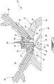
- a rotary internal combustion engine 10 known as a Wankel engine is schematically and partially shown.
- the rotary engine 10 is used in a compound cycle engine system such as described in Lents et al.'s US patent No. 7,753,036 issued July 13, 2010 or as described in Julien et al.'s US patent No. 7,775,044 issued August 17, 2010 .
- the compound cycle engine system may be used as a prime mover engine, such as on an aircraft or other vehicle, or in any other suitable application.
- air is compressed by a compressor before entering the Wankel engine, and the engine drives one or more turbine(s) of the compound engine.
- the rotary engine 10 is used without a turbocharger, with air at atmospheric pressure.
- the engine 10 comprises an outer body 12 having axially-spaced end walls 14 with a peripheral wall 18 extending therebetween to form a rotor cavity 20.
- the inner surface 19 of the peripheral wall 18 of the cavity 20 has a profile defining two lobes, which is preferably an epitrochoid.
- An inner body or rotor 24 is received within the cavity 20, with the geometrical axis of the rotor 24 being offset from and parallel to the axis of the outer body 12.
- the rotor 24 has axially spaced end faces 26 adjacent to the outer body end walls 14, and a peripheral face 28 extending therebetween.
- the peripheral face 28 defines three circumferentially-spaced apex portions 30 (only one of which is shown), and a generally triangular profile with outwardly arched sides.
- the apex portions 30 are in sealing engagement with the inner surface of peripheral wall 18 to form three rotating working chambers 32 (only two of which are partially shown) between the inner rotor 24 and outer body 12.
- a recess 38 is defined in the peripheral face 28 of the rotor 24 between each pair of adjacent apex portions 30, to form part of the corresponding chamber 32.
- Each rotor apex portion 30 has an apex seal 52 extending from one end face 26 to the other and protruding radially from the peripheral face 28. Each apex seal 52 is biased radially outwardly against the peripheral wall 18 through a respective spring. An end seal 54 engages each end of each apex seal 52, and is biased against the respective end wall 14 through a suitable spring.
- Each end face 26 of the rotor 24 has at least one arc-shaped face seal 60 running from each apex portion 30 to each adjacent apex portion 30, adjacent to but inwardly of the rotor periphery throughout its length.
- a spring urges each face seal 60 axially outwardly so that the face seal 60 projects axially away from the adjacent rotor end face 26 into sealing engagement with the adjacent end wall 14 of the cavity.
- Each face seal 60 is in sealing engagement with the end seal 54 adjacent each end thereof.
- the rotor 24 is journaled on an eccentric portion of a shaft and includes a phasing gear co-axial with the rotor axis, which is meshed with a fixed stator phasing gear secured to the outer body co-axially with the shaft.
- the shaft rotates the rotor 24 and the meshed gears guide the rotor 24 to perform orbital revolutions within the stator cavity.
- the rotor 24 performs three rotations for each orbital revolution. Oil seals are provided around the phasing gear to prevent leakage flow of lubricating oil radially outwardly thereof between the respective rotor end face 26 and outer body end wall 14.
- At least one inlet port is defined through one of the end walls 14 or the peripheral wall 18 for admitting air (atmospheric or compressed) into one of the working chambers 32
- at least one exhaust port is defined through one of the end walls 14 or the peripheral wall 18 for discharge of the exhaust gases from the working chambers 32.
- the inlet and exhaust ports are positioned relative to each other and relative to the ignition member and fuel injectors (further described below) such that during one orbital revolution of the rotor 24, each chamber 32 moves around the stator cavity 20 with a variable volume to undergo the four phases of intake, compression, expansion and exhaust, these phases being similar to the strokes in a reciprocating-type internal combustion engine having a four-stroke cycle.
- these ports are arranged such that the rotary engine 10 operates under the principle of the Miller or Atkinson cycle, with its volumetric compression ratio lower than its volumetric expansion ratio.
- the ports are arranged such that the volumetric compression and expansion ratios are equal or similar to one another.
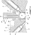
- An insert 34 is received in a corresponding hole 36 defined through the peripheral wall 18 of the outer body 12, for pilot fuel injection and ignition.
- the peripheral wall 18 also has a main injector elongated hole 40 defined therethrough, in communication with the rotor cavity 20 and spaced apart from the insert 34.
- a main fuel injector 42 is received and retained within this corresponding hole 40, with the tip 44 of the main injector 42 communicating with the cavity 20 at a point spaced apart from the insert 34.
- the main injector 42 is located rearwardly of the insert 34 with respect to the direction R of the rotor rotation and revolution, and is angled to direct fuel forwardly into each of the rotating chambers 32 sequentially with a tip hole pattern designed for an adequate spray.
- the insert includes an elongated body 46 extending across a thickness of the peripheral wall 18, with an enlarged flange 48 at its outer end which is biased away from a shoulder 50 defined in the peripheral wall 18, and against a gasket (not shown) made of an appropriate type of heat resistant material such as a silica based material.
- a washer 56 such as for example a steel or titanium washer
- spring 58 such as for example a wave spring or a Belleville spring, are provided between the flange 48 and the shoulder 50 of the peripheral wall 18.
- the spring 58 biases the body 46 against a cover 62 having a cross-section greater than that of the hole 36 and extending over an outer surface 64 of the peripheral wall 18.
- the cover 62 is connected to the peripheral wall 18, for example through brazing. Alternate types of connections can also be used, including but not limited to a connection through fasteners such as bolts, to help facilitate replacement of the insert if necessary.
- the insert body 46 has an inner surface 66 which is continuous with the inner surface 19 of the peripheral wall 18 to define the cavity 20.
- the insert hole 36 in the wall 18 defines a flange 68 extending in the insert hole 36 adjacent the inner surface 19, and the inner end of the insert body 46 is complementarily shaped to engage this flange 68, with a gasket 70 being received therebetween.
- the insert body 46 is made of a material having a greater heat resistance than that of the peripheral wall 18, which in a particular embodiment is made of aluminium. In this particular embodiment, the insert body 46 is made of an appropriate type of ceramic.
- the insert body 46 has a pilot subchamber 72 defined therein in communication with the rotor cavity 20.
- the subchamber 72 has a circular cross-section; alternate shapes are also possible.
- the subchamber 72 communicates with the cavity through at least one opening 74 defined in the inner surface 66.
- the subchamber 72 has a shape forming a reduced cross-section adjacent the opening 74, such that the opening 74 defines a restriction to the flow between the subchamber 72 and the cavity 20.
- the opening 74 may have various shapes and/or be defined by a pattern of multiple holes.
- the peripheral wall 18 has a pilot injector elongated hole 76 defined therethrough, at an angle with respect to the insert 34 and in communication with the subchamber 72.
- a pilot fuel injector 78 is received and retained within the corresponding hole 76, with the tip 80 of the pilot injector 78 being received in the subchamber 72.
- the insert body 46 and cover 62 have an ignition element elongated hole 82 defined therein extending along the direction of the transverse axis T of the outer body 12, also in communication with the subchamber 72.
- An ignition element 84 is received and retained within the corresponding hole 82, with the tip 86 of the ignition element 84 being received in the subchamber 72.
- the ignition element 84 is a glow plug. Alternate types of ignition elements 84 which may be used include, but are not limited to, plasma ignition, laser ignition, spark plug, microwave, etc.
- the pilot injector 78 and main injector 42 inject heavy fuel, e.g. diesel, kerosene (jet fuel), equivalent biofuel, etc. into the chambers 32.
- heavy fuel e.g. diesel, kerosene (jet fuel), equivalent biofuel, etc.
- at least 0.5% and up to 20% of the fuel is injected through the pilot injector 78, and the remainder is injected through the main injector 42.
- at most 10% of the fuel is injected through the pilot injector 78.
- at most 5% of the fuel is injected through the pilot injector 78.
- the main injector 42 injects the fuel such that each rotating chamber 32 when in the combustion phase contains a lean mixture of air and fuel.
- an insert 134 according to another embodiment is shown, engaged to the same outer body 12.
- the insert 134 extends across a thickness of the peripheral wall 18, and includes an inner body portion 146 and an outer body portion 162 which are attached together, for example through a high temperature braze joint 188.
- the outer body portion 162 has an enlarged flange 148 at its outer end which abuts the outer surface 64 of the peripheral wall 18 and is connected thereto, for example through bolts with appropriate sealing such as a gasket or crush seal (not shown).
- Alternate types of connections can also be used, including but not limited to a brazed connection.
- the inner body portion 146 has an inner surface 166 which is continuous with the inner surface 19 of the peripheral wall 18 to define the cavity 20.
- the inner end of the inner body portion 146 is complementarily shaped to engage the flange 68 extending in the insert hole 36 adjacent the inner surface 19, with a gasket 70 being received therebetween.
- the body portions 146, 162 are made of an appropriate type of super alloy such as a Nickel based super alloy.
- the pilot subchamber 72 is defined in the insert 134 at the junction between the body portions 146, 162, with the inner body portion 146 defining the opening 74 for communication between the subchamber 72 and the cavity 20.
- the outer body portion 162 has the ignition element elongated hole 82 defined therein along the direction of the transverse axis T and in communication with the subchamber 72.
- the ignition element 84 is received and retained within the corresponding hole 82, for example through threaded engagement. As in the previous embodiment, the tip 86 of the ignition element 84 is received in the subchamber 72.
- an insert 234 according to another embodiment is shown.
- the insert 234 is received in a corresponding hole 236 defined through the peripheral wall 18.
- the insert 234 includes an inner body portion 246 and an outer body portion 262 which are attached together, for example through a high temperature braze joint, with the subchamber 72 being defined at the junction of the two portions 246, 262.
- the inner body portion 246 defines the opening 74 for communication between the subchamber 72 and the cavity 20.
- the outer body portion 262 has the ignition element elongated hole 82 defined therethrough in communication with the subchamber 72.
- the outer body portion 262 includes an inner enlarged section 245 connected to the inner body portion 246 and defining the subchamber 72.
- the enlarged section 245 extends substantially across the width of the hole 236 around the subchamber 72, then tapers to a reduced width section 247 extending therefrom.
- the reduced width section 247 has at its outer end an enlarged flange 248 which abuts a shoulder 250 defined in the outer surface 64 of the peripheral wall 18 around the hole 236.
- An outer section 249 which in the embodiment shown has a width intermediate that of the sections 245 and 247, extends outwardly from the flange 248.
- the flange is connected to the shoulder, for example through bolts (not shown) with appropriate sealing such as a crush seal or a gasket (not shown) made of high temperature material, for example a silica based material or grafoil, between the flange 248 and shoulder 250. Alternate types of connections can also be used.
- the inner body portion 246 has an inner surface 266 which is continuous with the inner surface 19 of the peripheral wall 18 to define the cavity 20.
- the inner body portion 246 includes a groove defined therearound near the inner surface 266, in which an appropriate seal 251, for example a silica based gasket tape, is received in contact with the walls of the insert hole 236.
- an appropriate seal 251 for example a silica based gasket tape
- the walls of the insert holes 236 are straight adjacent the inner surface 19, i.e. there is no flange adjacent the inner surface 19.
- the volume of the subchamber 72 in the insert 34, 134, 234 is selected to obtain a stoichiometric mixture around ignition within an acceptable delay, with some of the exhaust product from the previous combustion cycle remaining in the subchamber 72.
- the volume of the subchamber 72 is at least 0.5% and up to 3.5% of the displacement volume, with the displacement volume being defined as the difference between the maximum and minimum volumes of one chamber 32.
- the volume of the subchamber 72 corresponds to from about 0.625% to about 1.25% of the displacement volume.
- the volume of the subchamber 72 may also be defined as a portion of the combustion volume, which is the sum of the minimum chamber volume V min (including the recess 38) and the volume of the subchamber V 2 itself.
- the subchamber 72 may help create a stable and powerful ignition zone to ignite the overall lean main combustion chamber 32 to create the stratified charge combustion.
- the subchamber 72 may improve combustion stability, particularly but not exclusively for a rotary engine which operates with heavy fuel below the self ignition of fuel.
- the insert 34, 134, 234 made of a heat resistant material may advantageously create a hot wall around the subchamber which may further help with ignition stability.
Landscapes
- Engineering & Computer Science (AREA)
- Mechanical Engineering (AREA)
- General Engineering & Computer Science (AREA)
- Chemical & Material Sciences (AREA)
- Combustion & Propulsion (AREA)
- Combustion Methods Of Internal-Combustion Engines (AREA)
- Fuel-Injection Apparatus (AREA)
Priority Applications (2)
| Application Number | Priority Date | Filing Date | Title |
|---|---|---|---|
| EP20193924.6A EP3772566A1 (en) | 2011-07-28 | 2012-07-25 | Stator for rotary internal combustion engine with pilot subchamber and method of injecting fuel |
| PL12177793T PL2551448T3 (pl) | 2011-07-28 | 2012-07-25 | Obrotowy silnik spalinowy wewnętrznego spalania z pilotującą komorą podrzędną i sposób wtrysku paliwa |
Applications Claiming Priority (2)
| Application Number | Priority Date | Filing Date | Title |
|---|---|---|---|
| US201161512593P | 2011-07-28 | 2011-07-28 | |
| US13/273,534 US9038594B2 (en) | 2011-07-28 | 2011-10-14 | Rotary internal combustion engine with pilot subchamber |
Related Child Applications (1)
| Application Number | Title | Priority Date | Filing Date |
|---|---|---|---|
| EP20193924.6A Division EP3772566A1 (en) | 2011-07-28 | 2012-07-25 | Stator for rotary internal combustion engine with pilot subchamber and method of injecting fuel |
Publications (3)
| Publication Number | Publication Date |
|---|---|
| EP2551448A2 EP2551448A2 (en) | 2013-01-30 |
| EP2551448A3 EP2551448A3 (en) | 2017-03-08 |
| EP2551448B1 true EP2551448B1 (en) | 2020-09-02 |
Family
ID=46603606
Family Applications (2)
| Application Number | Title | Priority Date | Filing Date |
|---|---|---|---|
| EP12177793.2A Active EP2551448B1 (en) | 2011-07-28 | 2012-07-25 | Rotary internal combustion engine with pilot subchamber and method of injecting fuel |
| EP20193924.6A Pending EP3772566A1 (en) | 2011-07-28 | 2012-07-25 | Stator for rotary internal combustion engine with pilot subchamber and method of injecting fuel |
Family Applications After (1)
| Application Number | Title | Priority Date | Filing Date |
|---|---|---|---|
| EP20193924.6A Pending EP3772566A1 (en) | 2011-07-28 | 2012-07-25 | Stator for rotary internal combustion engine with pilot subchamber and method of injecting fuel |
Country Status (6)
| Country | Link |
|---|---|
| US (3) | US9038594B2 (es) |
| EP (2) | EP2551448B1 (es) |
| CN (1) | CN102900514B (es) |
| CA (1) | CA2782749C (es) |
| ES (1) | ES2830299T3 (es) |
| PL (1) | PL2551448T3 (es) |
Families Citing this family (28)
| Publication number | Priority date | Publication date | Assignee | Title |
|---|---|---|---|---|
| US10557407B2 (en) * | 2011-07-28 | 2020-02-11 | Pratt & Whitney Canada Corp. | Rotary internal combustion engine with pilot subchamber |
| US9528434B1 (en) | 2011-07-28 | 2016-12-27 | Pratt & Whitney Canada Corp. | Rotary internal combustion engine with pilot subchamber |
| US9027345B2 (en) * | 2011-07-28 | 2015-05-12 | Pratt & Whitney Canada Corp. | Compound engine system with rotary engine |
| US10544732B2 (en) | 2011-07-28 | 2020-01-28 | Pratt & Whitney Canada Corp. | Rotary internal combustion engine with removable subchamber insert |
| US9038594B2 (en) * | 2011-07-28 | 2015-05-26 | Pratt & Whitney Canada Corp. | Rotary internal combustion engine with pilot subchamber |
| US9057321B2 (en) * | 2012-01-24 | 2015-06-16 | Wisconsin Alumni Research Foundation | Fuel reactivity stratification in rotary diesel engines |
| US9121277B2 (en) * | 2012-02-06 | 2015-09-01 | Pratt & Whitney Canada Corp. | Rotary internal combustion engine with cooled insert |
| US9353680B2 (en) | 2013-03-04 | 2016-05-31 | Pratt & Whitney Canada Corp. | Rotary internal combustion engine with pilot subchamber |
| US9399947B2 (en) | 2013-03-12 | 2016-07-26 | Pratt & Whitney Canada Corp. | Internal combustion engine with pilot and main injection |
| US9200563B2 (en) * | 2013-03-12 | 2015-12-01 | Pratt & Whitney Canada Corp. | Internal combustion engine with common rail pilot and main injection |
| US9334794B2 (en) | 2013-06-05 | 2016-05-10 | Pratt & Whitney Canada Corp. | Rotary internal combustion engine with pilot subchamber and ignition element |
| WO2016028760A1 (en) | 2014-08-18 | 2016-02-25 | Woodward, Inc. | Torch igniter |
| US10196923B2 (en) | 2014-08-28 | 2019-02-05 | Pratt & Whitney Canada Corp. | Operation of aircraft engines during transient conditions |
| CN108779702A (zh) * | 2015-10-08 | 2018-11-09 | 康明斯公司 | 预燃室组件 |
| US10041402B2 (en) | 2016-05-12 | 2018-08-07 | Pratt & Whitney Canada Corp. | Internal combustion engine with split pilot injection |
| US10082029B2 (en) | 2016-07-08 | 2018-09-25 | Pratt & Whitney Canada Corp. | Internal combustion engine with rotor having offset peripheral surface |
| US10072559B2 (en) * | 2016-09-23 | 2018-09-11 | Pratt & Whitney Canada Corp. | Method of operating an engine having a pilot subchamber at partial load conditions |
| US10815877B2 (en) | 2017-01-18 | 2020-10-27 | Pratt & Whitney Canada Corp. | Method of operating a rotary engine |
| US10544771B2 (en) * | 2017-06-14 | 2020-01-28 | Caterpillar Inc. | Fuel injector body with counterbore insert |
| US10145291B1 (en) | 2017-10-10 | 2018-12-04 | Pratt & Whitney Canada Corp. | Rotary engine and method of combusting fuel |
| DE102017009607A1 (de) | 2017-10-17 | 2019-04-18 | Daimler Ag | Zuführungs- und Zündvorrichtung für einen Gasmotor und Verfahren zum Betrieb einer Zuführungs- und Zündvorrichtung für einen Gasmotor |
| US10801394B2 (en) | 2017-11-29 | 2020-10-13 | Pratt & Whitney Canada Corp. | Rotary engine with pilot subchambers |
| CN109026366B (zh) * | 2018-08-01 | 2020-06-26 | 江苏大学 | 一种可变点火位置的缸内直喷转子发动机喷射引燃系统 |
| US11002185B2 (en) * | 2019-03-27 | 2021-05-11 | Pratt & Whitney Canada Corp. | Compounded internal combustion engine |
| US11421601B2 (en) | 2019-03-28 | 2022-08-23 | Woodward, Inc. | Second stage combustion for igniter |
| US11408329B2 (en) * | 2019-12-19 | 2022-08-09 | Board Of Trustees Of Michigan State University | Engine turbulent jet ignition system |
| US11060443B1 (en) * | 2020-02-25 | 2021-07-13 | Ford Global Technologies, Llc | Systems and methods for increasing oxygen levels in an active pre-chamber |
| CZ2021557A3 (cs) | 2021-12-09 | 2023-01-18 | Jan Novotný | Rotační spalovací motor |
Family Cites Families (162)
| Publication number | Priority date | Publication date | Assignee | Title |
|---|---|---|---|---|
| US3126876A (en) * | 1964-03-31 | Fuel injection systems for rotary combustion engines | ||
| US2093339A (en) | 1932-03-12 | 1937-09-14 | Oilmotors Corp | Internal combustion engine |
| US2739578A (en) | 1950-07-20 | 1956-03-27 | Daimler Benz Ag | Precombustion diesel engine |
| US2932289A (en) | 1958-10-20 | 1960-04-12 | Julius E Witzky | Precombustion chamber |
| US3058452A (en) | 1959-03-14 | 1962-10-16 | Motoren Werke Mannheim Ag | Internal combustion engines |
| US3102521A (en) * | 1960-12-20 | 1963-09-03 | Fmc Corp | Combustion apparatus for an internal combustion engine |
| DE1401982A1 (de) | 1961-12-09 | 1969-05-22 | Krupp Gmbh | Rotationskolbenmaschine |
| GB1193878A (en) * | 1966-06-15 | 1970-06-03 | Dynatech Corp | Internal Combustion Engine |
| JPS4912220B1 (es) | 1967-02-03 | 1974-03-23 | ||
| US3512907A (en) * | 1968-04-25 | 1970-05-19 | Nsu Motorenwerke Ag | Rotary combustion engine |
| US3508530A (en) | 1968-05-23 | 1970-04-28 | Dynatech Corp | Internal combustion engine |
| SU847937A3 (ru) | 1970-05-02 | 1981-07-15 | За витель | Двигатель внутреннего сгорани |
| US3857369A (en) * | 1971-04-27 | 1974-12-31 | H Sabet | Rotary piston engine with auxiliary chamber on its casing |
| IT964079B (it) | 1971-09-25 | 1974-01-21 | Sabet Huschang | Motore a pistoni in moto di circolazione |
| US3722480A (en) * | 1971-12-20 | 1973-03-27 | Curtiss Wright Corp | Rotary combustion engine with improved firing channel |
| US4096828A (en) | 1972-01-24 | 1978-06-27 | Toyo Kogyo Co. Ltd. | Rotary piston internal combustion engine |
| JPS5218849B2 (es) | 1972-05-15 | 1977-05-24 | ||
| US3941097A (en) * | 1973-06-09 | 1976-03-02 | Audi Nsu Auto Union Aktiengesellschaft | Rotary combustion engine having improved ignition means |
| GB1437528A (en) * | 1973-10-09 | 1976-05-26 | Rolls Royce Motors Ltd | Combustion chamber arrangement for rotary compression-ignition engines |
| US3861361A (en) | 1973-11-29 | 1975-01-21 | Gen Motors Corp | Rotary engine with piston scavenged precombustion chambers |
| US3894518A (en) * | 1973-12-12 | 1975-07-15 | Curtiss Wright Corp | Stratified charge rotary engine with dual fuel injection |
| US3985111A (en) * | 1973-12-17 | 1976-10-12 | Eaton Corporation | Article for defining an auxiliary compartment for an engine combustion chamber |
| JPS5216765B2 (es) | 1974-01-25 | 1977-05-11 | ||
| US4009688A (en) | 1974-03-04 | 1977-03-01 | Toyo Kogyo Co., Ltd. | Rotary piston type engine |
| US3910238A (en) | 1974-06-10 | 1975-10-07 | Richard James | Piston power unit with stratifying ignition system |
| JPS5125609A (es) * | 1974-08-24 | 1976-03-02 | Toyota Motor Co Ltd | |
| US3957021A (en) | 1974-10-15 | 1976-05-18 | Curtiss-Wright Corporation | Precombustion chamber rotary piston diesel engine |
| US4060058A (en) | 1975-11-28 | 1977-11-29 | Ford Motor Company | Internal combustion engine control system |
| JPS5266107A (en) | 1975-11-29 | 1977-06-01 | Riken Piston Ring Ind Co Ltd | Rotary piston engine |
| US4057036A (en) | 1976-03-01 | 1977-11-08 | Caterpillar Tractor Co. | Rotary engine with variable orifice prechamber |
| US4029058A (en) | 1976-03-15 | 1977-06-14 | Curtiss-Wright Corporation | Stratified charge rotary engine with side housing fuel injection |
| US4259932A (en) * | 1976-05-26 | 1981-04-07 | Ford Motor Company | Internal combustion engine control system |
| US4089306A (en) * | 1976-06-09 | 1978-05-16 | Caterpillar Tractor Co. | Port insulation for internal combustion engines |
| US4080934A (en) | 1976-09-09 | 1978-03-28 | Curtiss-Wright Corporation | Rotary engine with inserts in rotor faces |
| US4066044A (en) | 1976-09-09 | 1978-01-03 | Curtiss-Wright Corporation | Rotary engine with tongue and groove inserts in rotor faces |
| US4091789A (en) * | 1977-02-11 | 1978-05-30 | Curtiss-Wright Corporation | Stratified charge fuel injection system for rotary engine |
| US4083329A (en) | 1977-02-14 | 1978-04-11 | Curtiss-Wright Corporation | Rotary engine with a pilot fuel nozzle downstream of top center |
| US4085712A (en) | 1977-02-14 | 1978-04-25 | Curtiss-Wright Corporation | Rotary engine with pilot and main fuel nozzles downstream of top center |
| JPS5496614A (en) | 1978-01-13 | 1979-07-31 | Isuzu Motors Ltd | Voltex flow type conbustion chamber |
| US4239023A (en) * | 1978-12-07 | 1980-12-16 | Ford Motor Company | Fuel injection system for dual combustion chamber engine |
| DE2912155A1 (de) * | 1979-03-28 | 1980-10-09 | Kloeckner Humboldt Deutz Ag | Luftverdichtende, selbstzuendende hubkolbenbrennkraftmaschine |
| JPS55176435U (es) | 1979-06-05 | 1980-12-18 | ||
| JPS5625219A (en) | 1979-08-08 | 1981-03-11 | Matsushita Electric Ind Co Ltd | Manufacture of magnetic head |
| JPS5917252B2 (ja) | 1980-12-15 | 1984-04-20 | マツダ株式会社 | 過給機付ロ−タリピストンエンジンの吸気装置 |
| JPS5790251A (en) | 1981-09-30 | 1982-06-04 | Nissin Kogyo Kk | Negative pressure activated toggle joint and connector for master cylinder |
| JPS58162721A (ja) | 1982-03-19 | 1983-09-27 | Ngk Spark Plug Co Ltd | 内燃機関の副燃焼室 |
| JPS597726A (ja) | 1982-07-05 | 1984-01-14 | Mazda Motor Corp | デイ−ゼルエンジンの副室構成部材取付構造 |
| JPS5917252A (ja) | 1982-07-21 | 1984-01-28 | Hitachi Ltd | 半導体装置の製造方法 |
| JPS5946317A (ja) | 1982-09-07 | 1984-03-15 | Toyota Motor Corp | 内燃機関の燃焼室部品 |
| JPS59200012A (ja) | 1983-04-27 | 1984-11-13 | Kyocera Corp | 内燃機関の副燃焼室 |
| EP0141540B1 (en) | 1983-10-06 | 1989-01-04 | Mazda Motor Corporation | Structure of divided combustion chamber for diesel engine |
| JPS6093124A (ja) | 1983-10-27 | 1985-05-24 | Mazda Motor Corp | ロ−タリピストンエンジンの吸気装置 |
| JPS60212614A (ja) | 1984-04-06 | 1985-10-24 | Ngk Spark Plug Co Ltd | 内燃機関の副室 |
| JPS6183451A (ja) | 1984-09-29 | 1986-04-28 | Mazda Motor Corp | エンジンの副室の製造法 |
| JPS6193227A (ja) | 1984-10-11 | 1986-05-12 | Mazda Motor Corp | エンジンの副室の製造法 |
| US4616611A (en) | 1984-10-16 | 1986-10-14 | Ngk Insulators, Ltd. | Precombustion chamber construction of internal combustion engine |
| JPH0223788Y2 (es) | 1984-10-17 | 1990-06-28 | ||
| US4672933A (en) | 1984-10-30 | 1987-06-16 | 501 NGK Spark Plug Co. Ltd. | Precombustion chamber with insulating means |
| JPS61123714A (ja) | 1984-11-20 | 1986-06-11 | Ngk Insulators Ltd | 内燃機関の副室構造 |
| FR2575522B1 (fr) | 1984-12-28 | 1989-04-07 | Inst Francais Du Petrole | Dispositif pour controler le jet de melange carbure delivre par un systeme d'injection pneumatique |
| JPH0212265Y2 (es) | 1985-06-24 | 1990-04-06 | ||
| JPS6210418A (ja) | 1985-07-08 | 1987-01-19 | Mazda Motor Corp | 内燃機関のセラミックス製副室 |
| JPH029067Y2 (es) | 1985-07-30 | 1990-03-06 | ||
| JPS63179134A (ja) | 1986-10-29 | 1988-07-23 | Mazda Motor Corp | エンジンの吸気装置 |
| JPH0726553B2 (ja) | 1986-10-31 | 1995-03-29 | マツダ株式会社 | エンジンの吸気装置 |
| JPH0799114B2 (ja) | 1986-12-20 | 1995-10-25 | マツダ株式会社 | エンジンの制御装置 |
| US4759325A (en) * | 1987-01-28 | 1988-07-26 | Deere & Company | Rotary engine cooling system |
| JPH0536990Y2 (es) | 1987-02-23 | 1993-09-20 | ||
| US4873952A (en) | 1987-03-02 | 1989-10-17 | Ngk Spark Plug Co., Ltd. | Engine cylinder head with precombustion chambers using porous ceramics insert |
| JPS63140134U (es) | 1987-03-06 | 1988-09-14 | ||
| JPS6421220U (es) | 1987-07-29 | 1989-02-02 | ||
| JPS6480722A (en) | 1987-09-21 | 1989-03-27 | Mazda Motor | Intra-cylinder injection type engine |
| JPH01151722A (ja) | 1987-12-07 | 1989-06-14 | Mazda Motor Corp | エンジンの燃料噴射装置 |
| JPH0814253B2 (ja) | 1987-12-24 | 1996-02-14 | 三菱重工業株式会社 | 副室式ディーゼル機関の燃焼室 |
| JP2689132B2 (ja) | 1988-06-02 | 1997-12-10 | ヤマハ発動機株式会社 | 2サイクルディーゼルエンジン |
| US4889931A (en) | 1988-09-27 | 1989-12-26 | Salutar, Inc. | Manganese (II) chelate manufacture |
| JPH033940A (ja) | 1989-05-31 | 1991-01-10 | Mazda Motor Corp | エンジンの燃料噴射制御装置 |
| JPH0357818A (ja) * | 1989-07-27 | 1991-03-13 | Isuzu Motors Ltd | 副室の断熱構造 |
| JPH0357817A (ja) * | 1989-07-27 | 1991-03-13 | Isuzu Motors Ltd | 副室の断熱構造 |
| JPH0650054B2 (ja) * | 1989-08-10 | 1994-06-29 | いすゞ自動車株式会社 | 副室の断熱構造及びその製造法 |
| US5022366A (en) * | 1989-09-18 | 1991-06-11 | John Deere Technologies International, Inc. | Rotary engine with dual spark plugs and fuel injectors |
| US5178104A (en) | 1989-09-29 | 1993-01-12 | Yamaha Hatsudoki Kabushiki Kaisha | Two cycle diesel engine |
| JPH0650055B2 (ja) * | 1989-10-31 | 1994-06-29 | いすゞ自動車株式会社 | 副室断熱エンジンの構造 |
| JPH03199627A (ja) | 1989-12-28 | 1991-08-30 | Mazda Motor Corp | エンジンの吸気装置 |
| US5024193A (en) | 1990-02-06 | 1991-06-18 | Caterpillar Inc. | Fuel combustion system, method, and nozzle member therefor |
| JPH04140418A (ja) | 1990-09-28 | 1992-05-14 | Mazda Motor Corp | 副室付ディーゼルエンジンのピストン構造 |
| US5109817A (en) | 1990-11-13 | 1992-05-05 | Altronic, Inc. | Catalytic-compression timed ignition |
| JPH04298641A (ja) | 1991-01-29 | 1992-10-22 | Mazda Motor Corp | エンジンの燃料噴射装置 |
| JP3210027B2 (ja) | 1991-04-05 | 2001-09-17 | キヤノン株式会社 | カメラ |
| US5168846A (en) | 1991-06-14 | 1992-12-08 | Paul Marius A | Rotary engine with variable displacement |
| JPH0628345A (ja) | 1992-07-08 | 1994-02-04 | Fujitsu Ltd | 文書処理装置 |
| EP0663043A1 (de) | 1992-08-21 | 1995-07-19 | FALTAS MIKHAIL, William | Geregelte gemischbildung |
| US5522356A (en) | 1992-09-04 | 1996-06-04 | Spread Spectrum | Method and apparatus for transferring heat energy from engine housing to expansion fluid employed in continuous combustion, pinned vane type, integrated rotary compressor-expander engine system |
| JP3278922B2 (ja) | 1992-09-16 | 2002-04-30 | 凸版印刷株式会社 | パルプ発泡シートおよびその製造方法 |
| JPH06221176A (ja) | 1993-01-28 | 1994-08-09 | Mazda Motor Corp | ロータリピストンエンジンの補助空気供給装置 |
| CA2108108A1 (en) * | 1993-10-08 | 1995-04-09 | George F. Round | Rotary engine |
| US5444982A (en) | 1994-01-12 | 1995-08-29 | General Electric Company | Cyclonic prechamber with a centerbody |
| JP3003940U (ja) | 1994-05-06 | 1994-11-01 | 佐世保重工業株式会社 | 回転2連式水洗い装置 |
| CN1158152A (zh) | 1994-10-05 | 1997-08-27 | 冈村俊雄 | 旋转活塞式内燃机 |
| US5524587A (en) | 1995-03-03 | 1996-06-11 | Mallen Research Ltd. Partnership | Sliding vane engine |
| US5520148A (en) * | 1995-03-13 | 1996-05-28 | Isuzu Motors Limited | Heat insulating structure for swirl chambers |
| AT1623U1 (de) | 1995-05-19 | 1997-08-25 | Avl Verbrennungskraft Messtech | Einspritzsystem für eine insbesondere mit flüssiggas als kraftstoff oder kraftstoffkomponente betriebene brennkraftmaschine |
| FR2739895B1 (fr) | 1995-10-13 | 1997-12-12 | Inst Francais Du Petrole | Moteur a combustion interne a quatre temps et a allumage commande et injection directe de carburant |
| JP3199627B2 (ja) | 1996-01-30 | 2001-08-20 | 株式会社日平トヤマ | 両頭研削盤における自動定寸装置及び方法 |
| US5836282A (en) | 1996-12-27 | 1998-11-17 | Samsung Electronics Co., Ltd. | Method of reducing pollution emissions in a two-stroke sliding vane internal combustion engine |
| US6125813A (en) * | 1997-06-09 | 2000-10-03 | Patrick Power Products, Inc. | Prechamber combustion for a rotary diesel engine |
| US6162034A (en) | 1999-03-01 | 2000-12-19 | Mallen Research Ltd., Partnership | Vane pumping machine utilizing invar-class alloys for maximizing operating performance and reducing pollution emissions |
| US6244240B1 (en) | 1999-04-30 | 2001-06-12 | Mallen Research Limited Partnership | Rotary positive-displacement scavenging device for rotary vane pumping machine |
| RU2167316C2 (ru) | 1999-06-29 | 2001-05-20 | Вохмин Дмитрий Михайлович | Способ работы многотопливного двигателя внутреннего сгорания и многотопливный двигатель внутреннего сгорания |
| JP3233138B2 (ja) | 1999-09-27 | 2001-11-26 | 松下電器産業株式会社 | インバータ回路 |
| US6321713B1 (en) | 2000-08-02 | 2001-11-27 | Mallen Research Corporation | Hot wall combustion insert for a rotary vane pumping machine |
| WO2002027144A2 (en) | 2000-09-27 | 2002-04-04 | Alternative Power | Improved rotary piston engine and method of operation |
| US6570443B2 (en) | 2000-10-17 | 2003-05-27 | Asulab S.A. | Amplitude control of an alternating signal generated by an electronic device such as an oscillator circuit |
| DE10121036B4 (de) | 2001-04-28 | 2007-08-02 | Pfalz, Thomas, Dipl.-Ing. | Verdichtungsraum für einen Drehkolbenmotor |
| US6694944B2 (en) | 2001-12-20 | 2004-02-24 | Caterpillar Inc. | Rapid compression prechamber for internal combustion engine |
| JP2006518822A (ja) | 2003-02-24 | 2006-08-17 | プラット アンド ホイットニー カナダ コーポレイション | 低容積圧縮率の統合されたターボ複合ロータリエンジン |
| DE102004023409B4 (de) | 2004-05-12 | 2007-05-16 | Gottfried Schubert | Hochverdichtender Ottoverbrennungsmotor mit Drosselregelung, Fremdzündung und Kraftstoffdirekteinspritzung in eine Vorbrennkammer |
| NO322345B1 (no) | 2004-09-27 | 2006-09-18 | Rolls Royce Marine As | Anordning ved en forkammerenhet til en gassmotor |
| JP4298641B2 (ja) | 2004-12-09 | 2009-07-22 | セイコーエプソン株式会社 | 位置情報通信システムおよび位置情報通信端末 |
| US7922551B2 (en) * | 2005-06-07 | 2011-04-12 | Woodward, Inc. | Pre-chamber spark plug |
| EP2126314B1 (en) * | 2005-09-29 | 2019-07-17 | Prime Mover International, LLC | Hydrogen g-cycle rotary internal combustion engine |
| BRPI0709469B1 (pt) | 2006-04-07 | 2022-09-20 | David A. Blank | Método de controle de uma redução das concentrações de combustível desejadas e calor desejado, processo de modulação química da combustão de um combustível, e, aparelho, de melhoria de um motor a combustão interna que compreende um cilindro |
| US9010293B2 (en) | 2006-04-07 | 2015-04-21 | David A. Blank | Combustion control via homogeneous combustion radical ignition (HCRI) or partial HCRI in cyclic IC engines |
| WO2008043154A1 (en) | 2006-10-13 | 2008-04-17 | Bernhard Philberth | A combustion engine with fuel conditioning |
| JP4912220B2 (ja) | 2007-05-29 | 2012-04-11 | 三菱電機株式会社 | 受信機 |
| US7753036B2 (en) | 2007-07-02 | 2010-07-13 | United Technologies Corporation | Compound cycle rotary engine |
| US8033264B2 (en) | 2008-03-09 | 2011-10-11 | Rotary Power LLC | Rotary engine |
| RU2387851C2 (ru) | 2008-06-16 | 2010-04-27 | Курнайкин Вячеслав Валентинович | Форкамерный роторный двигатель внутреннего сгорания |
| ES2387374B1 (es) | 2010-02-01 | 2013-07-29 | Jesus Manuel Diaz Escaño | Motor rotativo que utiliza para su funcionamiento combustibles alternativos |
| AT509876B1 (de) | 2010-08-20 | 2011-12-15 | Ge Jenbacher Gmbh & Co Ohg | Vorkammersystem |
| EP2681537B1 (fr) | 2011-02-28 | 2022-06-15 | Safran Aircraft Engines | Dispositif de recherche de defauts sur des pieces par endoscopie |
| EP2497902B1 (en) | 2011-03-10 | 2016-09-07 | Uav Engines Ltd | Rotary Engine Rotor |
| US20120227397A1 (en) | 2011-03-10 | 2012-09-13 | Willi Martin L | Gaseous fuel-powered engine system having turbo-compounding |
| US10557407B2 (en) | 2011-07-28 | 2020-02-11 | Pratt & Whitney Canada Corp. | Rotary internal combustion engine with pilot subchamber |
| US9528434B1 (en) | 2011-07-28 | 2016-12-27 | Pratt & Whitney Canada Corp. | Rotary internal combustion engine with pilot subchamber |
| US9038594B2 (en) * | 2011-07-28 | 2015-05-26 | Pratt & Whitney Canada Corp. | Rotary internal combustion engine with pilot subchamber |
| DE102011083143A1 (de) | 2011-09-21 | 2013-03-21 | Robert Bosch Gmbh | Vorkammermodul für eine Laserzündkerze |
| US9217360B2 (en) | 2011-12-01 | 2015-12-22 | Cummins Intellectual Property, Inc. | Prechamber device for internal combustion engine |
| US9057321B2 (en) | 2012-01-24 | 2015-06-16 | Wisconsin Alumni Research Foundation | Fuel reactivity stratification in rotary diesel engines |
| US9121277B2 (en) | 2012-02-06 | 2015-09-01 | Pratt & Whitney Canada Corp. | Rotary internal combustion engine with cooled insert |
| CN102691564A (zh) | 2012-06-01 | 2012-09-26 | 慈溪三环柴油机有限公司 | 一种新型内燃机涡流燃烧室 |
| US9926843B2 (en) | 2012-07-20 | 2018-03-27 | Pratt & Whitney Canada Corp. | Compound cycle engine |
| US10107195B2 (en) | 2012-07-20 | 2018-10-23 | Pratt & Whitney Canada Corp. | Compound cycle engine |
| JP5559846B2 (ja) | 2012-07-25 | 2014-07-23 | 株式会社Nttドコモ | 移動通信システム、呼制御装置、移動局及び移動通信方法 |
| JP6093124B2 (ja) | 2012-07-26 | 2017-03-08 | HybridMom株式会社 | 監督システム |
| US9664047B2 (en) | 2012-08-23 | 2017-05-30 | Mallen Research Limited Partnership | Positive displacement rotary devices with uniquely configured voids |
| US10161296B2 (en) | 2012-11-27 | 2018-12-25 | Board Of Trustees Of Michigan State University | Internal combustion engine |
| US9353680B2 (en) | 2013-03-04 | 2016-05-31 | Pratt & Whitney Canada Corp. | Rotary internal combustion engine with pilot subchamber |
| US10280830B2 (en) | 2013-03-08 | 2019-05-07 | Pratt & Whitney Canada Corp. | System for pilot subchamber temperature control |
| US9200563B2 (en) | 2013-03-12 | 2015-12-01 | Pratt & Whitney Canada Corp. | Internal combustion engine with common rail pilot and main injection |
| US9399947B2 (en) | 2013-03-12 | 2016-07-26 | Pratt & Whitney Canada Corp. | Internal combustion engine with pilot and main injection |
| US9334794B2 (en) | 2013-06-05 | 2016-05-10 | Pratt & Whitney Canada Corp. | Rotary internal combustion engine with pilot subchamber and ignition element |
| JP6221176B2 (ja) | 2013-12-09 | 2017-11-01 | 三菱日立パワーシステムズ株式会社 | ガスタービン冷却系統、これを備えているガスタービンプラント、及びガスタービンの高温部冷却方法 |
| SK6949Y1 (sk) | 2014-01-08 | 2014-11-04 | Prpic Ivan | Rotačný lopatkový motor |
| JP3199627U (ja) | 2015-06-19 | 2015-09-03 | 株式会社福島製作所 | ボールペンのリフィルアダプター |
| WO2017006266A1 (en) | 2015-07-06 | 2017-01-12 | Denovo Genomics, Inc. | Variants of the subtilisin carlsberg polypeptide with decreased thermostability |
| CN108291476B (zh) | 2015-10-06 | 2021-02-02 | 伍德沃德有限公司 | 无源预燃室直接喷射燃烧 |
| US9890690B2 (en) | 2015-10-06 | 2018-02-13 | Woodward, Inc. | Passive prechamber direct injection combustion |
| US20160053667A1 (en) | 2015-11-02 | 2016-02-25 | Caterpillar Inc. | Prechamber assembly for an engine |
| GB2545417A (en) | 2015-12-14 | 2017-06-21 | Caterpillar Energy Solutions Gmbh | Prechamber assembly for internal combustion engine |
| US10072559B2 (en) | 2016-09-23 | 2018-09-11 | Pratt & Whitney Canada Corp. | Method of operating an engine having a pilot subchamber at partial load conditions |
| JP3210027U (ja) | 2017-02-08 | 2017-04-20 | 運華 李 | 硫化物浄化装置の邪魔板機構 |
-
2011
- 2011-10-14 US US13/273,534 patent/US9038594B2/en active Active
-
2012
- 2012-07-06 CA CA2782749A patent/CA2782749C/en active Active
- 2012-07-25 PL PL12177793T patent/PL2551448T3/pl unknown
- 2012-07-25 ES ES12177793T patent/ES2830299T3/es active Active
- 2012-07-25 EP EP12177793.2A patent/EP2551448B1/en active Active
- 2012-07-25 EP EP20193924.6A patent/EP3772566A1/en active Pending
- 2012-07-27 CN CN201210262898.0A patent/CN102900514B/zh active Active
-
2015
- 2015-05-07 US US14/706,457 patent/US10125676B2/en active Active
-
2018
- 2018-10-23 US US16/168,045 patent/US10697365B2/en active Active
Non-Patent Citations (1)
| Title |
|---|
| None * |
Also Published As
| Publication number | Publication date |
|---|---|
| US10697365B2 (en) | 2020-06-30 |
| US9038594B2 (en) | 2015-05-26 |
| CN102900514B (zh) | 2016-07-13 |
| EP2551448A2 (en) | 2013-01-30 |
| EP3772566A1 (en) | 2021-02-10 |
| CA2782749A1 (en) | 2013-01-28 |
| US20190055882A1 (en) | 2019-02-21 |
| EP2551448A3 (en) | 2017-03-08 |
| ES2830299T3 (es) | 2021-06-03 |
| PL2551448T3 (pl) | 2021-07-19 |
| CN102900514A (zh) | 2013-01-30 |
| CA2782749C (en) | 2020-10-20 |
| US10125676B2 (en) | 2018-11-13 |
| US20150240710A1 (en) | 2015-08-27 |
| US20130025567A1 (en) | 2013-01-31 |
Similar Documents
| Publication | Publication Date | Title |
|---|---|---|
| US10697365B2 (en) | Rotary internal combustion engine with pilot subchamber | |
| US10578012B2 (en) | Rotary internal combustion engine with pilot subchamber | |
| US10267217B2 (en) | Internal combustion engine with common rail injection | |
| EP2775117B1 (en) | Rotary internal combustion engine with pilot subchamber | |
| EP2778367B1 (en) | Internal combustion engine with pilot and main injection | |
| US10557407B2 (en) | Rotary internal combustion engine with pilot subchamber | |
| EP3299607B1 (en) | Method of operating an engine having a pilot subchamber at partial load conditions | |
| US11306651B2 (en) | Method of operating an internal combustion engine |
Legal Events
| Date | Code | Title | Description |
|---|---|---|---|
| PUAI | Public reference made under article 153(3) epc to a published international application that has entered the european phase |
Free format text: ORIGINAL CODE: 0009012 |
|
| AK | Designated contracting states |
Kind code of ref document: A2 Designated state(s): AL AT BE BG CH CY CZ DE DK EE ES FI FR GB GR HR HU IE IS IT LI LT LU LV MC MK MT NL NO PL PT RO RS SE SI SK SM TR |
|
| AX | Request for extension of the european patent |
Extension state: BA ME |
|
| PUAL | Search report despatched |
Free format text: ORIGINAL CODE: 0009013 |
|
| AK | Designated contracting states |
Kind code of ref document: A3 Designated state(s): AL AT BE BG CH CY CZ DE DK EE ES FI FR GB GR HR HU IE IS IT LI LT LU LV MC MK MT NL NO PL PT RO RS SE SI SK SM TR |
|
| AX | Request for extension of the european patent |
Extension state: BA ME |
|
| RIC1 | Information provided on ipc code assigned before grant |
Ipc: F01C 11/00 20060101ALI20170127BHEP Ipc: F01C 20/10 20060101ALI20170127BHEP Ipc: F01C 20/06 20060101ALI20170127BHEP Ipc: F04C 29/00 20060101ALI20170127BHEP Ipc: F01C 20/24 20060101ALI20170127BHEP Ipc: F01C 21/18 20060101ALI20170127BHEP Ipc: F01C 21/10 20060101ALI20170127BHEP Ipc: F01C 1/22 20060101AFI20170127BHEP Ipc: F01C 21/06 20060101ALI20170127BHEP Ipc: F01C 21/08 20060101ALI20170127BHEP |
|
| STAA | Information on the status of an ep patent application or granted ep patent |
Free format text: STATUS: REQUEST FOR EXAMINATION WAS MADE |
|
| 17P | Request for examination filed |
Effective date: 20170907 |
|
| RBV | Designated contracting states (corrected) |
Designated state(s): AL AT BE BG CH CY CZ DE DK EE ES FI FR GB GR HR HU IE IS IT LI LT LU LV MC MK MT NL NO PL PT RO RS SE SI SK SM TR |
|
| GRAP | Despatch of communication of intention to grant a patent |
Free format text: ORIGINAL CODE: EPIDOSNIGR1 |
|
| STAA | Information on the status of an ep patent application or granted ep patent |
Free format text: STATUS: GRANT OF PATENT IS INTENDED |
|
| INTG | Intention to grant announced |
Effective date: 20200206 |
|
| GRAS | Grant fee paid |
Free format text: ORIGINAL CODE: EPIDOSNIGR3 |
|
| GRAA | (expected) grant |
Free format text: ORIGINAL CODE: 0009210 |
|
| STAA | Information on the status of an ep patent application or granted ep patent |
Free format text: STATUS: THE PATENT HAS BEEN GRANTED |
|
| AK | Designated contracting states |
Kind code of ref document: B1 Designated state(s): AL AT BE BG CH CY CZ DE DK EE ES FI FR GB GR HR HU IE IS IT LI LT LU LV MC MK MT NL NO PL PT RO RS SE SI SK SM TR |
|
| REG | Reference to a national code |
Ref country code: GB Ref legal event code: FG4D |
|
| REG | Reference to a national code |
Ref country code: AT Ref legal event code: REF Ref document number: 1309006 Country of ref document: AT Kind code of ref document: T Effective date: 20200915 Ref country code: CH Ref legal event code: EP |
|
| REG | Reference to a national code |
Ref country code: DE Ref legal event code: R096 Ref document number: 602012072066 Country of ref document: DE |
|
| REG | Reference to a national code |
Ref country code: IE Ref legal event code: FG4D |
|
| REG | Reference to a national code |
Ref country code: CH Ref legal event code: NV Representative=s name: VALIPAT S.A. C/O BOVARD SA NEUCHATEL, CH |
|
| REG | Reference to a national code |
Ref country code: LT Ref legal event code: MG4D |
|
| PG25 | Lapsed in a contracting state [announced via postgrant information from national office to epo] |
Ref country code: NO Free format text: LAPSE BECAUSE OF FAILURE TO SUBMIT A TRANSLATION OF THE DESCRIPTION OR TO PAY THE FEE WITHIN THE PRESCRIBED TIME-LIMIT Effective date: 20201202 Ref country code: GR Free format text: LAPSE BECAUSE OF FAILURE TO SUBMIT A TRANSLATION OF THE DESCRIPTION OR TO PAY THE FEE WITHIN THE PRESCRIBED TIME-LIMIT Effective date: 20201203 Ref country code: SE Free format text: LAPSE BECAUSE OF FAILURE TO SUBMIT A TRANSLATION OF THE DESCRIPTION OR TO PAY THE FEE WITHIN THE PRESCRIBED TIME-LIMIT Effective date: 20200902 Ref country code: FI Free format text: LAPSE BECAUSE OF FAILURE TO SUBMIT A TRANSLATION OF THE DESCRIPTION OR TO PAY THE FEE WITHIN THE PRESCRIBED TIME-LIMIT Effective date: 20200902 Ref country code: LT Free format text: LAPSE BECAUSE OF FAILURE TO SUBMIT A TRANSLATION OF THE DESCRIPTION OR TO PAY THE FEE WITHIN THE PRESCRIBED TIME-LIMIT Effective date: 20200902 Ref country code: HR Free format text: LAPSE BECAUSE OF FAILURE TO SUBMIT A TRANSLATION OF THE DESCRIPTION OR TO PAY THE FEE WITHIN THE PRESCRIBED TIME-LIMIT Effective date: 20200902 Ref country code: BG Free format text: LAPSE BECAUSE OF FAILURE TO SUBMIT A TRANSLATION OF THE DESCRIPTION OR TO PAY THE FEE WITHIN THE PRESCRIBED TIME-LIMIT Effective date: 20201202 |
|
| REG | Reference to a national code |
Ref country code: NL Ref legal event code: MP Effective date: 20200902 |
|
| PG25 | Lapsed in a contracting state [announced via postgrant information from national office to epo] |
Ref country code: LV Free format text: LAPSE BECAUSE OF FAILURE TO SUBMIT A TRANSLATION OF THE DESCRIPTION OR TO PAY THE FEE WITHIN THE PRESCRIBED TIME-LIMIT Effective date: 20200902 Ref country code: RS Free format text: LAPSE BECAUSE OF FAILURE TO SUBMIT A TRANSLATION OF THE DESCRIPTION OR TO PAY THE FEE WITHIN THE PRESCRIBED TIME-LIMIT Effective date: 20200902 |
|
| PG25 | Lapsed in a contracting state [announced via postgrant information from national office to epo] |
Ref country code: RO Free format text: LAPSE BECAUSE OF FAILURE TO SUBMIT A TRANSLATION OF THE DESCRIPTION OR TO PAY THE FEE WITHIN THE PRESCRIBED TIME-LIMIT Effective date: 20200902 Ref country code: SM Free format text: LAPSE BECAUSE OF FAILURE TO SUBMIT A TRANSLATION OF THE DESCRIPTION OR TO PAY THE FEE WITHIN THE PRESCRIBED TIME-LIMIT Effective date: 20200902 Ref country code: PT Free format text: LAPSE BECAUSE OF FAILURE TO SUBMIT A TRANSLATION OF THE DESCRIPTION OR TO PAY THE FEE WITHIN THE PRESCRIBED TIME-LIMIT Effective date: 20210104 Ref country code: NL Free format text: LAPSE BECAUSE OF FAILURE TO SUBMIT A TRANSLATION OF THE DESCRIPTION OR TO PAY THE FEE WITHIN THE PRESCRIBED TIME-LIMIT Effective date: 20200902 Ref country code: EE Free format text: LAPSE BECAUSE OF FAILURE TO SUBMIT A TRANSLATION OF THE DESCRIPTION OR TO PAY THE FEE WITHIN THE PRESCRIBED TIME-LIMIT Effective date: 20200902 |
|
| PG25 | Lapsed in a contracting state [announced via postgrant information from national office to epo] |
Ref country code: IS Free format text: LAPSE BECAUSE OF FAILURE TO SUBMIT A TRANSLATION OF THE DESCRIPTION OR TO PAY THE FEE WITHIN THE PRESCRIBED TIME-LIMIT Effective date: 20210102 Ref country code: AL Free format text: LAPSE BECAUSE OF FAILURE TO SUBMIT A TRANSLATION OF THE DESCRIPTION OR TO PAY THE FEE WITHIN THE PRESCRIBED TIME-LIMIT Effective date: 20200902 |
|
| REG | Reference to a national code |
Ref country code: ES Ref legal event code: FG2A Ref document number: 2830299 Country of ref document: ES Kind code of ref document: T3 Effective date: 20210603 Ref country code: DE Ref legal event code: R097 Ref document number: 602012072066 Country of ref document: DE |
|
| PG25 | Lapsed in a contracting state [announced via postgrant information from national office to epo] |
Ref country code: SK Free format text: LAPSE BECAUSE OF FAILURE TO SUBMIT A TRANSLATION OF THE DESCRIPTION OR TO PAY THE FEE WITHIN THE PRESCRIBED TIME-LIMIT Effective date: 20200902 |
|
| PLBE | No opposition filed within time limit |
Free format text: ORIGINAL CODE: 0009261 |
|
| STAA | Information on the status of an ep patent application or granted ep patent |
Free format text: STATUS: NO OPPOSITION FILED WITHIN TIME LIMIT |
|
| 26N | No opposition filed |
Effective date: 20210603 |
|
| PG25 | Lapsed in a contracting state [announced via postgrant information from national office to epo] |
Ref country code: SI Free format text: LAPSE BECAUSE OF FAILURE TO SUBMIT A TRANSLATION OF THE DESCRIPTION OR TO PAY THE FEE WITHIN THE PRESCRIBED TIME-LIMIT Effective date: 20200902 Ref country code: DK Free format text: LAPSE BECAUSE OF FAILURE TO SUBMIT A TRANSLATION OF THE DESCRIPTION OR TO PAY THE FEE WITHIN THE PRESCRIBED TIME-LIMIT Effective date: 20200902 |
|
| PG25 | Lapsed in a contracting state [announced via postgrant information from national office to epo] |
Ref country code: MC Free format text: LAPSE BECAUSE OF FAILURE TO SUBMIT A TRANSLATION OF THE DESCRIPTION OR TO PAY THE FEE WITHIN THE PRESCRIBED TIME-LIMIT Effective date: 20200902 |
|
| REG | Reference to a national code |
Ref country code: BE Ref legal event code: MM Effective date: 20210731 |
|
| PG25 | Lapsed in a contracting state [announced via postgrant information from national office to epo] |
Ref country code: LU Free format text: LAPSE BECAUSE OF NON-PAYMENT OF DUE FEES Effective date: 20210725 |
|
| PG25 | Lapsed in a contracting state [announced via postgrant information from national office to epo] |
Ref country code: IE Free format text: LAPSE BECAUSE OF NON-PAYMENT OF DUE FEES Effective date: 20210725 Ref country code: BE Free format text: LAPSE BECAUSE OF NON-PAYMENT OF DUE FEES Effective date: 20210731 |
|
| PG25 | Lapsed in a contracting state [announced via postgrant information from national office to epo] |
Ref country code: HU Free format text: LAPSE BECAUSE OF FAILURE TO SUBMIT A TRANSLATION OF THE DESCRIPTION OR TO PAY THE FEE WITHIN THE PRESCRIBED TIME-LIMIT; INVALID AB INITIO Effective date: 20120725 Ref country code: CY Free format text: LAPSE BECAUSE OF FAILURE TO SUBMIT A TRANSLATION OF THE DESCRIPTION OR TO PAY THE FEE WITHIN THE PRESCRIBED TIME-LIMIT Effective date: 20200902 |
|
| P01 | Opt-out of the competence of the unified patent court (upc) registered |
Effective date: 20230530 |
|
| PGFP | Annual fee paid to national office [announced via postgrant information from national office to epo] |
Ref country code: IT Payment date: 20230620 Year of fee payment: 12 |
|
| REG | Reference to a national code |
Ref country code: AT Ref legal event code: UEP Ref document number: 1309006 Country of ref document: AT Kind code of ref document: T Effective date: 20200902 |
|
| PGFP | Annual fee paid to national office [announced via postgrant information from national office to epo] |
Ref country code: ES Payment date: 20230801 Year of fee payment: 12 Ref country code: CH Payment date: 20230801 Year of fee payment: 12 Ref country code: AT Payment date: 20230622 Year of fee payment: 12 |
|
| PGFP | Annual fee paid to national office [announced via postgrant information from national office to epo] |
Ref country code: DE Payment date: 20230620 Year of fee payment: 12 |
|
| PG25 | Lapsed in a contracting state [announced via postgrant information from national office to epo] |
Ref country code: MK Free format text: LAPSE BECAUSE OF FAILURE TO SUBMIT A TRANSLATION OF THE DESCRIPTION OR TO PAY THE FEE WITHIN THE PRESCRIBED TIME-LIMIT Effective date: 20200902 |
|
| PG25 | Lapsed in a contracting state [announced via postgrant information from national office to epo] |
Ref country code: TR Free format text: LAPSE BECAUSE OF FAILURE TO SUBMIT A TRANSLATION OF THE DESCRIPTION OR TO PAY THE FEE WITHIN THE PRESCRIBED TIME-LIMIT Effective date: 20200902 |
|
| PGFP | Annual fee paid to national office [announced via postgrant information from national office to epo] |
Ref country code: GB Payment date: 20240620 Year of fee payment: 13 |
|
| PGFP | Annual fee paid to national office [announced via postgrant information from national office to epo] |
Ref country code: CZ Payment date: 20240625 Year of fee payment: 13 |
|
| PGFP | Annual fee paid to national office [announced via postgrant information from national office to epo] |
Ref country code: FR Payment date: 20240619 Year of fee payment: 13 |
|
| PGFP | Annual fee paid to national office [announced via postgrant information from national office to epo] |
Ref country code: PL Payment date: 20240625 Year of fee payment: 13 |