EP2544038A2 - Laminiertes optisches brechungselement und optisches system - Google Patents
Laminiertes optisches brechungselement und optisches system Download PDFInfo
- Publication number
- EP2544038A2 EP2544038A2 EP12187153A EP12187153A EP2544038A2 EP 2544038 A2 EP2544038 A2 EP 2544038A2 EP 12187153 A EP12187153 A EP 12187153A EP 12187153 A EP12187153 A EP 12187153A EP 2544038 A2 EP2544038 A2 EP 2544038A2
- Authority
- EP
- European Patent Office
- Prior art keywords
- light
- doe
- grating
- diffraction gratings
- laminated
- Prior art date
- Legal status (The legal status is an assumption and is not a legal conclusion. Google has not performed a legal analysis and makes no representation as to the accuracy of the status listed.)
- Withdrawn
Links
- 230000003287 optical effect Effects 0.000 title claims abstract description 62
- 239000000463 material Substances 0.000 claims abstract description 17
- 239000006185 dispersion Substances 0.000 claims description 14
- 238000001228 spectrum Methods 0.000 claims description 7
- 230000004075 alteration Effects 0.000 description 15
- 210000001747 pupil Anatomy 0.000 description 14
- 239000000758 substrate Substances 0.000 description 13
- 230000005540 biological transmission Effects 0.000 description 4
- 238000010030 laminating Methods 0.000 description 4
- 239000004973 liquid crystal related substance Substances 0.000 description 4
- 238000003475 lamination Methods 0.000 description 3
- 101150026388 LAC14 gene Proteins 0.000 description 2
- 230000015572 biosynthetic process Effects 0.000 description 2
- 230000000694 effects Effects 0.000 description 2
- 238000000034 method Methods 0.000 description 2
- 230000009467 reduction Effects 0.000 description 2
- 241000511976 Hoya Species 0.000 description 1
- 230000002547 anomalous effect Effects 0.000 description 1
- 230000008901 benefit Effects 0.000 description 1
- 230000008859 change Effects 0.000 description 1
- 230000007423 decrease Effects 0.000 description 1
- 230000004907 flux Effects 0.000 description 1
- 239000011521 glass Substances 0.000 description 1
- 239000002184 metal Substances 0.000 description 1
- 238000012986 modification Methods 0.000 description 1
- 230000004048 modification Effects 0.000 description 1
- 239000002105 nanoparticle Substances 0.000 description 1
- 239000011368 organic material Substances 0.000 description 1
- 239000011295 pitch Substances 0.000 description 1
- 239000011347 resin Substances 0.000 description 1
- 229920005989 resin Polymers 0.000 description 1
- 230000004043 responsiveness Effects 0.000 description 1
- 230000001629 suppression Effects 0.000 description 1
- 230000002123 temporal effect Effects 0.000 description 1
- 238000002834 transmittance Methods 0.000 description 1
Images





Classifications
-
- G—PHYSICS
- G02—OPTICS
- G02B—OPTICAL ELEMENTS, SYSTEMS OR APPARATUS
- G02B27/00—Optical systems or apparatus not provided for by any of the groups G02B1/00 - G02B26/00, G02B30/00
- G02B27/42—Diffraction optics, i.e. systems including a diffractive element being designed for providing a diffractive effect
- G02B27/44—Grating systems; Zone plate systems
-
- G—PHYSICS
- G02—OPTICS
- G02B—OPTICAL ELEMENTS, SYSTEMS OR APPARATUS
- G02B5/00—Optical elements other than lenses
- G02B5/18—Diffraction gratings
- G02B5/1814—Diffraction gratings structurally combined with one or more further optical elements, e.g. lenses, mirrors, prisms or other diffraction gratings
- G02B5/1819—Plural gratings positioned on the same surface, e.g. array of gratings
- G02B5/1823—Plural gratings positioned on the same surface, e.g. array of gratings in an overlapping or superposed manner
-
- G—PHYSICS
- G02—OPTICS
- G02B—OPTICAL ELEMENTS, SYSTEMS OR APPARATUS
- G02B27/00—Optical systems or apparatus not provided for by any of the groups G02B1/00 - G02B26/00, G02B30/00
- G02B27/0025—Optical systems or apparatus not provided for by any of the groups G02B1/00 - G02B26/00, G02B30/00 for optical correction, e.g. distorsion, aberration
- G02B27/0037—Optical systems or apparatus not provided for by any of the groups G02B1/00 - G02B26/00, G02B30/00 for optical correction, e.g. distorsion, aberration with diffracting elements
-
- G—PHYSICS
- G02—OPTICS
- G02B—OPTICAL ELEMENTS, SYSTEMS OR APPARATUS
- G02B27/00—Optical systems or apparatus not provided for by any of the groups G02B1/00 - G02B26/00, G02B30/00
- G02B27/42—Diffraction optics, i.e. systems including a diffractive element being designed for providing a diffractive effect
- G02B27/4205—Diffraction optics, i.e. systems including a diffractive element being designed for providing a diffractive effect having a diffractive optical element [DOE] contributing to image formation, e.g. whereby modulation transfer function MTF or optical aberrations are relevant
- G02B27/4211—Diffraction optics, i.e. systems including a diffractive element being designed for providing a diffractive effect having a diffractive optical element [DOE] contributing to image formation, e.g. whereby modulation transfer function MTF or optical aberrations are relevant correcting chromatic aberrations
-
- G—PHYSICS
- G02—OPTICS
- G02B—OPTICAL ELEMENTS, SYSTEMS OR APPARATUS
- G02B27/00—Optical systems or apparatus not provided for by any of the groups G02B1/00 - G02B26/00, G02B30/00
- G02B27/42—Diffraction optics, i.e. systems including a diffractive element being designed for providing a diffractive effect
- G02B27/4272—Diffraction optics, i.e. systems including a diffractive element being designed for providing a diffractive effect having plural diffractive elements positioned sequentially along the optical path
Definitions
- the present invention relates to a laminated diffractive optical element, and particularly to a laminated diffractive optical element with reduced chromatic aberration.
- DOEs Diffractive optical elements
- the DOEs are nearly always provided with reduced optical powers to be used in optical systems for multicolor lights so as to correct the chromatic aberration well. This is because a dispersion of the DOE is extremely larger than that of refraction and therefore a DOE having an optical power significantly contributing to image-formation increases differences of diffraction powers for various wavelengths, which increases chromatic aberration generated by the DOE. Thus, performances of the DOEs are not utilized enough.
- Japanese Patent No. 3966303 discloses a pickup lens having on its each surface binary step with different heights. This pickup lens sets the height of binary steps on one surface to a value equal to an integral multiple of a wavelength that is not desired to be diffracted through the binary steps and to a value different from an integral multiple of a wavelength that is desired to be diffracted therethrough, thereby diffracting only light of the desired wavelength.
- Japanese Patent Laid-Open No. 9-189892 discloses a displaying optical system including a liquid crystal DOE.
- the displaying optical system performs highspeed time division switching of a wavelength of light from a light source such as R ⁇ G ⁇ B ⁇ R ⁇ ..., and switches parameters of the liquid crystal DOE in synchronization with the time division switching, thereby suppressing generation of aberration.
- a curvature radius is -28.63mm and the longitudinal chromatic aberration of R-B is 0.775mm.
- the DOEs disclosed in Japanese Patent No. 3966303 and Japanese Patent Laid-Open No. 9-189892 may solve the above-described problem.
- the DOE disclosed in Japanese Patent No. 3966303 is a multi-level zone plate DOE, which may obtain an insufficient diffraction efficiency.
- the liquid crystal DOE disclosed in Japanese Patent Laid-Open No. 9-189892 involves a problem that accuracy of an annular zone interval depends on a size of a pixel cell and a problem that temporal responsiveness thereof cannot be sufficiently improved.
- the present invention provides a laminated diffractive optical element having a strong power and being capable of reducing chromatic aberration generated due to diffraction.
- the present invention provides as one aspect thereof a laminated diffractive optical element including plural diffraction gratings laminated with each other, the respective diffraction gratings being formed of a same light-transmissive material, and plural reflective films formed on grating surfaces of the respective diffraction gratings, each of the reflective films being disposed between the diffraction gratings.
- Each of the reflective films reflects light in a specific wavelength range and transmits light in a wavelength range different from the specific wavelength range, the specific wavelength ranges for the respective reflective films being different from each other.
- the grating surfaces of the respective diffraction gratings are formed in shapes different from each other according to the specific wavelength ranges for the respective reflective films.
- the present invention provides as another aspect thereof a laminated diffractive optical element including plural diffraction gratings laminated with each other, the respective diffraction gratings being formed of light-transmissive materials different from each other.
- Grating surfaces of the respective diffraction gratings are formed in shapes different from each other.
- Refractive indices of the diffraction gratings adjacent to each other in a lamination direction in which the diffraction gratings are laminated have mutually different dispersion characteristics for one specific color light.
- Each of the grating surfaces diffracts the specific color light.
- FIG. 1 shows a reflective laminated DOE (laminated diffractive optical element) 1 that is a first example (Example 1) of the present invention.
- the DOE 1 is constituted by laminating three diffraction grating layers (diffraction gratings) including a first layer 21, a second layer 22 and a third layer 23.
- the three diffraction grating layers are formed of a same light-transmissive medium (material), and refractive indices (n( ⁇ )) thereof are also equal to each other.
- a grating surface 13 is formed as a mirror surface that reflects light transmitted through the first to third layers 21-23.
- This mirror surface may be formed of a reflective film vapor-deposited on a back surface of the third layer 23 or may be formed of a metal plate.
- Forming the first to third layers 21-23 with the same material as described above makes the entire DOE 1 thin.
- the first to third layers 21 to 23 are formed of resin
- forming the grating surface 13 that includes the mirror surface on a substrate and then sequentially forming thereon the third layer 23, the dichroic film, the second layer 22, the dichroic film and the first layer 21 can produce the DOE.
- an anti-reflection film may be formed on a light entrance side surface 10 of the first layer 21.
- disposing a transparent substrate further on a light entrance side than the surface 10 and then sequentially forming thereon the first layer 21, the dichroic film, the second layer 22, the dichroic film, the third layer 23 and the reflective film can produce the DOE as a back-surface mirror.
- light in the second wavelength range is reflected and diffracted at the predetermined diffraction order by the grating surface 12, and then is again transmitted through the second layer 22 and the first layer 21 to exit from the DOE 1 through the surface 10 without being diffracted by the grating surface 11.
- light in a wavelength range other than the second wavelength is transmitted through the grating surface 12 without being diffracted since the refractive indices of the second and third layers 22 and 23 are equal to each other.
- the DOE 1 of this example can set, if optimizing the shape of each of the grating surfaces for the wavelength range which is desired to be diffracted by that grating surface (that is, the specific wavelength range), a power to diffract light in that wavelength range independently.
- the DOE 1 of this example can reduce chromatic aberration. That is, the grating surfaces 11 and 12 in the DOE 1 of this example have mutually different shapes according to the specific wavelength ranges for the reflective films respectively formed on the grating surfaces 11 and 12.
- Reference characters DL 1 , DL 2 and DL 3 respectively denote light rays reflected and diffracted at the grating surfaces 11, 12 and 13.
- Reference characters P 1 , P 2 and P 3 and d 1 , d 2 and d 3 respectively denote annular zone intervals (pitches of the annular zones) P and grating heights d at the incident points of the light rays DL 1 , DL 2 and DL 3 on the grating surfaces 11, 12 and 13.
- annular zone intervals P 1 , P 2 and P 3 and the grating heights d 1 , d 2 and d 3 on the grating surfaces 11, 12 and 13 are mutually different on a same incident ray axis along which the light rays DL 1 , DL 2 and DL 3 trace.
- ⁇ ⁇ n N C n ⁇ r 2 ⁇ n (r: distance from annular zone center)
- FIG. 2 shows a transmissive laminated DOE 2 that is a second example (Example 2) of the present invention.
- This DOE 2 is also constituted by laminating plural diffraction grating layers (diffraction gratings) each diffracting monochromatic light, which is the same as the DOE 1 of Example 1.
- the DOE 2 has a color correction function for two wavelengths.
- the DOE 2 is constituted by laminating three light-transmissive media including a first layer 41, a second layer 42 and a third layer 43.
- the three light-transmissive media are different from each other, and refractive indices thereof are also mutually different.
- the refractive indices of the light-transmissive media forming the first layer 41, the second layer 42 and the third layer 43 are respectively represented by n 1 ( ⁇ ), n 2 ( ⁇ ) and n 3 ( ⁇ ).
- a grating surface 11 disposed between the first layer 41 and the second layer 42 and a grating surface 12 disposed between the second layer 42 and the third layer 43 are formed as grating surfaces having a blazed structure.
- the shapes of the blazed structures of the grating surfaces 11 and 12 are mutually different.
- Light IL including at least light in wavelengths ⁇ 1 and ⁇ 2 enters the DOE 2 through a surface 10, and then exits from the DOE 2 through a surface 14.
- the grating surfaces 11 and 12 and the surface 10 and 14 may be provided with an anti-reflection film.
- a light-transmissive substrate may be disposed further on a light entrance side than the surface 10 or further on a light exit side than the surface 14.
- the light-transmissive substrate serves as a holding member, which makes it possible to thin the layer on the light entrance side or on the light exit side.
- the grating surface 12 is formed such that an annular zone interval P 2 and a grating height d 2 can provide a required diffraction power and a required diffraction efficiency for the wavelength ⁇ 2 . Therefore, at the grating surface 12, the light in the wavelength ⁇ 2 is transmitted therethrough and diffracted in a predetermined direction, and the light in the wavelength ⁇ 1 is transmitted therethrough without being diffracted to enter the third layer 43.
- FIG. 11 shows the dispersion characteristics of the light-transmissive media forming the first to third layers 41-43.
- ⁇ 1 is 640nm and ⁇ 2 is 410nm.
- Forming the DOE 2 using materials having such dispersion characteristics enables application of the DOE 2 to an optical element such as a pickup lens that converges two laser light fluxes in the wavelengths ⁇ 1 and ⁇ 2 on focal points different from each other on a same axis.
- the DOE has a structure including four layers. Light of the wavelength ⁇ 1 is diffracted by a grating surface between a first layer and a second layer independently, light of the wavelength ⁇ 2 is diffracted by a grating surface between the second layer and a third layer independently, and light of the wavelength ⁇ 3 is diffracted by a grating surface between the third layer and a fourth layer independently.
- a dichroic film is formed on the grating surface 11. This dichroic film reflects and diffracts light in a wavelength range (first wavelength range) from red (R) to infrared. Another dichroic film is formed on the grating surface 12. This dichroic film reflects and diffracts light in a wavelength range (second wavelength range) from ultraviolet to blue (B). The grating surface 13 reflects and diffracts at least light in a wavelength range of green (G) (third wavelength range) transmitted through the grating surfaces 11 and 12.
- G green
- This structure enables the two dichroic films to independently reflect and diffract the light in the first wavelength range that is a short side wavelength range and the light in the second wavelength range that is a long side wavelength range. Furthermore, this structure enables at least the grating surface that reflects the light in the third wavelength range between the first and second wavelength ranges to diffract that light with a required power.
- the first grating surface 11 that reflects the light in the wavelength range from blue to ultraviolet and the second grating surface 12 that reflects the light in the wavelength range from red to infrared are arranged in no particular order from the light entrance side.
- the third grating surface 13 that reflects the light in a wavelength range transmitted through the dichroic films formed on the first and second grating surfaces 11 and 12 may be formed on a side opposite to the light entrance side with respect to the first and second grating surfaces 11 and 12.
- This optical system is configured such that an incident angle is larger than a reflection angle.
- the configuration of the dichroic film is expressed as follows:
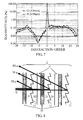
- FIG. 6 shows a reflective diffraction efficiency of the principal ray of the wavelength ⁇ B when the incident angle thereof is 45° and the incident point (y) thereof is 3.0mm.
- FIG.7 shows transmissive diffraction efficiencies of principal rays of the wavelengths ⁇ G and ⁇ R . The transmissive diffraction efficiencies are calculated by rigorous coupled wave analysis. The reflective diffraction efficiency of the +5th order diffracted light of the wavelength ⁇ B is 82.39%, and the transmittances of the 0th order diffracted lights of the wavelengths ⁇ R and ⁇ G are 94.6% and 90.1%, respectively.
- relative intensities of the transmissive diffracted lights of diffraction orders other than the 0th order in the wavelengths ⁇ R and ⁇ G are less than 0.2%, which means that most of the light of the wavelength ⁇ B is reflected and diffracted and most of the lights of the other wavelengths are transmitted without being diffracted.
- the intensities of diffracted lights of the wavelength ⁇ B whose diffraction orders are other than the +5th order are about 1%, such slightly high intensities can be reduced by adjustment of the shape of the grating such as tilting of a grating side face.
- a reflective DOE in which a dichroic film is formed on a grating surface 11 between layers 21 and 22 formed of a same light-transmissive medium whose refractive index is n( ⁇ ) is formed on a light-transmissive substrate 30 whose refractive index is n p ( ⁇ ), which constitutes a first reflective diffraction unit.
- the refractive index n( ⁇ ) may be equal to the refractive index n p ( ⁇ ) or may be different therefrom.
- the dichroic film formed on the grating surface 11 reflects and diffracts light of a wavelength ⁇ R (R-light).
- another reflective DOE in which a dichroic film is formed on a grating surface 12 between layers 23 and 24 formed of the same light-transmissive medium whose refractive index is n( ⁇ ) is formed on another light-transmissive substrate 30 whose refractive index is n p ( ⁇ ), which constitutes a second reflective diffraction unit.
- the refractive index n( ⁇ ) may be equal to the refractive index n p ( ⁇ ) or may be different therefrom.
- the dichroic film formed on the grating surface 12 reflects and diffracts light of a wavelength ⁇ B (B-light).
- Still another reflective DOE in which a dichroic film is formed on a grating surface 13 of a layer 25 formed of the light-transmissive medium whose refractive index is n( ⁇ ) is formed on still another light-transmissive substrate 30 whose refractive index is n p ( ⁇ ), which constitutes a third reflective diffraction unit.
- the refractive index n( ⁇ ) may be equal to the refractive index n p ( ⁇ ) or may be different therefrom.
- the grating surface 13 is formed as a mirror surface that reflects and diffracts light of a wavelength ⁇ G (G-light).
- the first to third reflective diffraction units are disposed adjacently to each other so as to form air layers 31 therebetween to be laminated with each other.
- Boundaries of the substrates 30 and the layers do not influence diffraction. If the substrates 30 are parallel plain plates, an incident angle of the light on each layer does not change. Even when the substrates 30 are curved plates and thereby have refractive powers, it is only necessary to optimize a phase difference function for each layer according to the refractive powers.
- the first to third reflective diffraction units may be disposed in contact with each other so as not to form the air layers 31 therebetween to be laminated with each other, as shown in FIG. 9 .
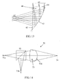
- Example 5 Description will be made of a fifth example (Example 5) as still another specific example of the reflective laminated DOE 1 described in Example 1. Although in Examples 3 and 4 the reflective laminated DOE is used alone in the optical system, the reflective laminated DOE may be used in combination with refractive elements or reflective elements.
- This example has a relationship that a reflection angle is larger than an incident angle to reduce a thickness and a size of the prism element 60.
- Numerical data of the above-described optical system is shown below.
- a coordinate system in the numerical data is the same as that described in Example 3.
- the annular zone intervals P k on the DOE at an incident point where a light ray for an angle of view of 0° are calculated as follows, as in Example 3, since the incident angle thereof is 23.37° and a diffraction angle thereof is 45.4649° :
- E-FD8 is used as the light-transmissive medium for the first layer 41
- LAC14 is used as the light-transmissive medium for the second layer 42
- E-FD15 is used as the light-transmissive medium for the third layer 43 (Those glasses are manufactured by HOYA corporation).
- FIG. 15 shows dispersion characteristics of E-FD8, LAC14 and E-FD15.
- the coefficients C m of the grating surface 12 (for the wavelength ⁇ 2) between the second and third layers are set as follows:
- the present invention can provide a laminated diffractive optical element with reduced chromatic aberration generated due to diffraction while having a strong power.
Landscapes
- Physics & Mathematics (AREA)
- General Physics & Mathematics (AREA)
- Optics & Photonics (AREA)
- Diffracting Gratings Or Hologram Optical Elements (AREA)
- Lenses (AREA)
- Optical Elements Other Than Lenses (AREA)
Applications Claiming Priority (2)
| Application Number | Priority Date | Filing Date | Title |
|---|---|---|---|
| JP2009241989A JP5059079B2 (ja) | 2009-10-21 | 2009-10-21 | 積層型回折光学素子および光学系 |
| EP10824816A EP2491441A4 (de) | 2009-10-21 | 2010-10-05 | Laminiertes optisches brechungselement und optisches system |
Related Parent Applications (1)
| Application Number | Title | Priority Date | Filing Date |
|---|---|---|---|
| EP10824816.2 Division | 2010-10-05 |
Publications (2)
| Publication Number | Publication Date |
|---|---|
| EP2544038A2 true EP2544038A2 (de) | 2013-01-09 |
| EP2544038A3 EP2544038A3 (de) | 2013-03-13 |
Family
ID=43900195
Family Applications (2)
| Application Number | Title | Priority Date | Filing Date |
|---|---|---|---|
| EP10824816A Withdrawn EP2491441A4 (de) | 2009-10-21 | 2010-10-05 | Laminiertes optisches brechungselement und optisches system |
| EP12187153A Withdrawn EP2544038A3 (de) | 2009-10-21 | 2010-10-05 | Laminiertes optisches brechungselement und optisches system |
Family Applications Before (1)
| Application Number | Title | Priority Date | Filing Date |
|---|---|---|---|
| EP10824816A Withdrawn EP2491441A4 (de) | 2009-10-21 | 2010-10-05 | Laminiertes optisches brechungselement und optisches system |
Country Status (5)
| Country | Link |
|---|---|
| US (1) | US8885254B2 (de) |
| EP (2) | EP2491441A4 (de) |
| JP (1) | JP5059079B2 (de) |
| CN (1) | CN102597821A (de) |
| WO (1) | WO2011048967A1 (de) |
Families Citing this family (34)
| Publication number | Priority date | Publication date | Assignee | Title |
|---|---|---|---|---|
| JP5059079B2 (ja) | 2009-10-21 | 2012-10-24 | キヤノン株式会社 | 積層型回折光学素子および光学系 |
| JP2012243378A (ja) * | 2011-05-24 | 2012-12-10 | Asahi Glass Co Ltd | 光学素子及び光ヘッド装置 |
| JP5972100B2 (ja) * | 2012-08-13 | 2016-08-17 | キヤノン株式会社 | 反射型回折素子 |
| JP2015225217A (ja) * | 2014-05-28 | 2015-12-14 | 凸版印刷株式会社 | 分光用光学シート |
| NZ773822A (en) | 2015-03-16 | 2022-07-29 | Magic Leap Inc | Methods and systems for diagnosing and treating health ailments |
| IL256276B (en) | 2015-06-15 | 2022-09-01 | Magic Leap Inc | Display system with optical components for coupling multiple light streams |
| EP3440497B1 (de) | 2016-04-08 | 2023-08-16 | Magic Leap, Inc. | Systeme der erweiterten realität und verfahren mit linsenelementen mit veränderlicher brennweite |
| US9791703B1 (en) | 2016-04-13 | 2017-10-17 | Microsoft Technology Licensing, Llc | Waveguides with extended field of view |
| US10067347B2 (en) | 2016-04-13 | 2018-09-04 | Microsoft Technology Licensing, Llc | Waveguides with improved intensity distributions |
| US10353202B2 (en) * | 2016-06-09 | 2019-07-16 | Microsoft Technology Licensing, Llc | Wrapped waveguide with large field of view |
| US10095045B2 (en) | 2016-09-12 | 2018-10-09 | Microsoft Technology Licensing, Llc | Waveguide comprising a bragg polarization grating |
| US11067860B2 (en) | 2016-11-18 | 2021-07-20 | Magic Leap, Inc. | Liquid crystal diffractive devices with nano-scale pattern and methods of manufacturing the same |
| IL312713A (en) | 2016-11-18 | 2024-07-01 | Magic Leap Inc | Waveguide light multiplexer using crossed gratings |
| KR102506485B1 (ko) | 2016-11-18 | 2023-03-03 | 매직 립, 인코포레이티드 | 넓은 입사 각도 범위들의 광을 방향전환시키기 위한 다중층 액정 회절 격자들 |
| KR102533671B1 (ko) | 2016-11-18 | 2023-05-16 | 매직 립, 인코포레이티드 | 공간 가변적 액정 회절 격자들 |
| IL304304B2 (en) | 2016-12-08 | 2024-08-01 | Magic Leap Inc | Diffractive devices based on cholesteric liquid crystal |
| KR102550742B1 (ko) | 2016-12-14 | 2023-06-30 | 매직 립, 인코포레이티드 | 표면 정렬 패턴들의 소프트-임프린트 복제를 이용한 액정들의 패터닝 |
| AU2018210527B2 (en) | 2017-01-23 | 2022-12-01 | Magic Leap, Inc. | Eyepiece for virtual, augmented, or mixed reality systems |
| IL307602A (en) | 2017-02-23 | 2023-12-01 | Magic Leap Inc | Variable focus virtual imagers based on polarization conversion |
| CN115576048A (zh) | 2017-03-21 | 2023-01-06 | 奇跃公司 | 用于组合视场的具有不同衍射光栅的堆叠波导 |
| IL269317B2 (en) | 2017-03-21 | 2023-11-01 | Magic Leap Inc | An eye imaging device that uses optical refractive elements |
| DE102017205844A1 (de) * | 2017-04-06 | 2018-10-11 | Robert Bosch Gmbh | Lichttransmissionselement, optische Empfangseinheit, optische Aktoreinheit, LiDAR-System, Arbeitsvorrichtung und Fahrzeug |
| US10838248B2 (en) * | 2017-07-20 | 2020-11-17 | Benq Materials Corporation | Optical film |
| JP6981074B2 (ja) * | 2017-07-25 | 2021-12-15 | Agc株式会社 | 光学素子 |
| JP7204363B2 (ja) * | 2017-08-04 | 2023-01-16 | キヤノン株式会社 | 回折光学素子、その製造方法および光学機器 |
| EP3685215B1 (de) | 2017-09-21 | 2024-01-03 | Magic Leap, Inc. | Anzeige mit erweiterter realität mit wellenleiter zur erfassung von bildern des auges und/oder der umgebung |
| CA3084011C (en) | 2017-12-15 | 2024-06-11 | Magic Leap, Inc. | Eyepieces for augmented reality display system |
| US10802382B2 (en) * | 2018-07-24 | 2020-10-13 | Qualcomm Incorporated | Adjustable light projector for flood illumination and active depth sensing |
| CN109116577B (zh) * | 2018-07-30 | 2020-10-20 | 杭州光粒科技有限公司 | 一种全息隐形眼镜及其应用 |
| WO2020106824A1 (en) | 2018-11-20 | 2020-05-28 | Magic Leap, Inc. | Eyepieces for augmented reality display system |
| WO2020183887A1 (ja) | 2019-03-08 | 2020-09-17 | ソニー株式会社 | 複合型回折素子、器具、及び映像投射システム |
| CN114286962A (zh) | 2019-06-20 | 2022-04-05 | 奇跃公司 | 用于增强现实显示系统的目镜 |
| CN112886264B (zh) * | 2019-11-29 | 2025-09-26 | 广州方邦电子股份有限公司 | 电磁散射膜 |
| CN115685573B (zh) * | 2022-11-07 | 2026-02-06 | 湖北长江新型显示产业创新中心有限公司 | 一种场镜、显示装置及电子设备 |
Citations (4)
| Publication number | Priority date | Publication date | Assignee | Title |
|---|---|---|---|---|
| JPH09189892A (ja) | 1996-01-09 | 1997-07-22 | Olympus Optical Co Ltd | 回折光学系およびこれに用いる液晶回折レンズ |
| JP3966303B2 (ja) | 2003-04-24 | 2007-08-29 | コニカミノルタオプト株式会社 | 回折光学素子及びそれを用いた光ピックアップ装置 |
| JP2009241989A (ja) | 2008-03-31 | 2009-10-22 | Kobe Steel Ltd | 耐突刺し性が優れた飲料用アルミニウム缶 |
| EP2491441A1 (de) | 2009-10-21 | 2012-08-29 | Canon Kabushiki Kaisha | Laminiertes optisches brechungselement und optisches system |
Family Cites Families (23)
| Publication number | Priority date | Publication date | Assignee | Title |
|---|---|---|---|---|
| JPH0389892A (ja) | 1989-06-19 | 1991-04-15 | Yokogawa Electric Corp | 電動ファンのドライブ回路 |
| JPH04211202A (ja) * | 1990-03-19 | 1992-08-03 | Canon Inc | 反射型回折格子および該回折格子を用いた装置 |
| JP4088283B2 (ja) * | 1995-08-29 | 2008-05-21 | オリンパス株式会社 | 回折光学素子およびそれを備える光学系並びに光学装置 |
| US6781756B1 (en) * | 1995-08-29 | 2004-08-24 | Olympus Corporation | Diffractive optical element |
| EP0953161B1 (de) * | 1997-01-17 | 2004-11-17 | Cymer, Inc. | Reflektierender überzug für wiederholtes beugungsgitter |
| JP3472097B2 (ja) * | 1997-08-20 | 2003-12-02 | キヤノン株式会社 | 回折光学素子及びそれを用いた光学系 |
| JP4149021B2 (ja) * | 1998-01-14 | 2008-09-10 | オリンパス株式会社 | 光学系 |
| JP4416917B2 (ja) * | 2000-05-19 | 2010-02-17 | パナソニック株式会社 | 光学素子およびそれを用いた光学装置 |
| US6449097B1 (en) * | 2000-06-05 | 2002-09-10 | Lightchip, Inc. | Diffraction grating for wavelength division multiplexing/demultiplexing devices |
| JP2002062417A (ja) | 2000-06-07 | 2002-02-28 | Canon Inc | 回折光学素子、該回折光学素子を有する光学系及び光学機器、回折光学素子の製造方法、回折光学素子製造用の金型 |
| JP4359713B2 (ja) * | 2000-11-24 | 2009-11-04 | コニカミノルタホールディングス株式会社 | 回折光学素子 |
| JP4345256B2 (ja) | 2001-02-14 | 2009-10-14 | 旭硝子株式会社 | 波長選択性回折素子および光ヘッド装置 |
| US6805490B2 (en) * | 2002-09-30 | 2004-10-19 | Nokia Corporation | Method and system for beam expansion in a display device |
| JP2004126394A (ja) * | 2002-10-04 | 2004-04-22 | Nikon Corp | 回折光学素子 |
| JP2005128260A (ja) | 2003-10-23 | 2005-05-19 | Toyo Commun Equip Co Ltd | ブレーズド回折格子を備えた広帯域波長板とこれを用いた光ピックアップとブレーズド回折格子の製造方法 |
| JP4251967B2 (ja) | 2003-11-13 | 2009-04-08 | 株式会社リコー | 偏光回折光学素子、光ピックアップ及び光ディスクドライブ装置 |
| US7206107B2 (en) * | 2004-12-13 | 2007-04-17 | Nokia Corporation | Method and system for beam expansion in a display device |
| US7573640B2 (en) * | 2005-04-04 | 2009-08-11 | Mirage Innovations Ltd. | Multi-plane optical apparatus |
| JP4518009B2 (ja) | 2005-11-29 | 2010-08-04 | 旭硝子株式会社 | 3波長用回折素子、位相板付3波長用回折素子および光ヘッド装置 |
| TWI406007B (zh) | 2006-07-20 | 2013-08-21 | 尼康股份有限公司 | Optical system and eyepiece |
| JP2008203821A (ja) | 2007-01-22 | 2008-09-04 | Canon Inc | 積層型回折光学素子 |
| JP4963668B2 (ja) | 2007-12-11 | 2012-06-27 | キヤノン株式会社 | 画像観察装置 |
| JP2010020855A (ja) * | 2008-07-11 | 2010-01-28 | Fujinon Corp | 複数波長用反射型回折格子およびこれを備えた光ピックアップ装置 |
-
2009
- 2009-10-21 JP JP2009241989A patent/JP5059079B2/ja not_active Expired - Fee Related
-
2010
- 2010-10-05 EP EP10824816A patent/EP2491441A4/de not_active Withdrawn
- 2010-10-05 EP EP12187153A patent/EP2544038A3/de not_active Withdrawn
- 2010-10-05 US US13/503,175 patent/US8885254B2/en not_active Expired - Fee Related
- 2010-10-05 WO PCT/JP2010/067807 patent/WO2011048967A1/en not_active Ceased
- 2010-10-05 CN CN201080046745.1A patent/CN102597821A/zh active Pending
Patent Citations (4)
| Publication number | Priority date | Publication date | Assignee | Title |
|---|---|---|---|---|
| JPH09189892A (ja) | 1996-01-09 | 1997-07-22 | Olympus Optical Co Ltd | 回折光学系およびこれに用いる液晶回折レンズ |
| JP3966303B2 (ja) | 2003-04-24 | 2007-08-29 | コニカミノルタオプト株式会社 | 回折光学素子及びそれを用いた光ピックアップ装置 |
| JP2009241989A (ja) | 2008-03-31 | 2009-10-22 | Kobe Steel Ltd | 耐突刺し性が優れた飲料用アルミニウム缶 |
| EP2491441A1 (de) | 2009-10-21 | 2012-08-29 | Canon Kabushiki Kaisha | Laminiertes optisches brechungselement und optisches system |
Also Published As
| Publication number | Publication date |
|---|---|
| WO2011048967A1 (en) | 2011-04-28 |
| US20120206812A1 (en) | 2012-08-16 |
| CN102597821A (zh) | 2012-07-18 |
| EP2491441A4 (de) | 2013-03-20 |
| US8885254B2 (en) | 2014-11-11 |
| EP2544038A3 (de) | 2013-03-13 |
| JP2011090074A (ja) | 2011-05-06 |
| JP5059079B2 (ja) | 2012-10-24 |
| EP2491441A1 (de) | 2012-08-29 |
Similar Documents
| Publication | Publication Date | Title |
|---|---|---|
| EP2544038A2 (de) | Laminiertes optisches brechungselement und optisches system | |
| EP2482103B1 (de) | Verfahren zur Herstellung eines diffraktiven optischen Elements | |
| US8139295B2 (en) | Optical system and eye piece | |
| US6560019B2 (en) | Diffractive optical element and optical system having the same | |
| JP4336412B2 (ja) | 回折光学素子及びそれを用いた光学系 | |
| US5737125A (en) | Diffractive optical element and optical system including the same | |
| EP3779551A1 (de) | Kameraobjektiv, kameramodul und endgerät | |
| EP2492715A1 (de) | Hinten befestigte Linse, optisches Bildgebungssystem und Bildaufnahmevorrichtung | |
| EP2184627B1 (de) | Beugendes optisches system und optisches okularsystem | |
| US20070058251A1 (en) | Polarization beam splitter and optical system using the same, and image displaying apparatus, using the same | |
| US20200249433A1 (en) | Electronic device | |
| JPH1184118A (ja) | 回折光学素子及びそれを用いた光学系 | |
| JP2008309901A (ja) | 光学系及びそれを備えた画像取得装置 | |
| CN103370641B (zh) | 使用自由曲面棱镜的衍射光学系统及图像拍摄装置 | |
| JP2012163831A (ja) | 超広角レンズおよびこれを搭載した撮像装置 | |
| JP3652260B2 (ja) | 回折光学素子、該回折光学素子を有する光学系、撮影装置、観察装置 | |
| JP4227210B2 (ja) | 回折光学素子及びそれを用いた光学系 | |
| EP1376161B1 (de) | Optisches Beugungselement und damit ausgestattetes optisches System | |
| JP5765998B2 (ja) | 回折光学素子、光学系および光学機器 | |
| JP5496258B2 (ja) | 積層型回折光学素子および光学系 | |
| JP4743607B2 (ja) | フレネルレンズ、および、このフレネルレンズを用いた液晶プロジェクタ | |
| US20250020847A1 (en) | Metasurface waveguide coupler for display unit | |
| EP4270078A1 (de) | Projektionslinsensystem, projektionsgerät und elektronische vorrichtung | |
| US20230168413A1 (en) | Optical system and image capturing apparatus including the same | |
| JP2005164773A (ja) | 回折光学素子及びそれを用いた投射用レンズ |
Legal Events
| Date | Code | Title | Description |
|---|---|---|---|
| PUAI | Public reference made under article 153(3) epc to a published international application that has entered the european phase |
Free format text: ORIGINAL CODE: 0009012 |
|
| AC | Divisional application: reference to earlier application |
Ref document number: 2491441 Country of ref document: EP Kind code of ref document: P |
|
| AK | Designated contracting states |
Kind code of ref document: A2 Designated state(s): AL AT BE BG CH CY CZ DE DK EE ES FI FR GB GR HR HU IE IS IT LI LT LU LV MC MK MT NL NO PL PT RO RS SE SI SK SM TR |
|
| PUAL | Search report despatched |
Free format text: ORIGINAL CODE: 0009013 |
|
| AK | Designated contracting states |
Kind code of ref document: A3 Designated state(s): AL AT BE BG CH CY CZ DE DK EE ES FI FR GB GR HR HU IE IS IT LI LT LU LV MC MK MT NL NO PL PT RO RS SE SI SK SM TR |
|
| RIC1 | Information provided on ipc code assigned before grant |
Ipc: G02B 27/44 20060101ALI20130201BHEP Ipc: G02B 27/00 20060101AFI20130201BHEP Ipc: G02B 5/18 20060101ALI20130201BHEP Ipc: G02B 27/42 20060101ALI20130201BHEP |
|
| 17P | Request for examination filed |
Effective date: 20130913 |
|
| RBV | Designated contracting states (corrected) |
Designated state(s): AL AT BE BG CH CY CZ DE DK EE ES FI FR GB GR HR HU IE IS IT LI LT LU LV MC MK MT NL NO PL PT RO RS SE SI SK SM TR |
|
| STAA | Information on the status of an ep patent application or granted ep patent |
Free format text: STATUS: THE APPLICATION HAS BEEN WITHDRAWN |
|
| 18W | Application withdrawn |
Effective date: 20140228 |