EP2496733B1 - Procédé d'évaporation - Google Patents
Procédé d'évaporation Download PDFInfo
- Publication number
- EP2496733B1 EP2496733B1 EP10775984.7A EP10775984A EP2496733B1 EP 2496733 B1 EP2496733 B1 EP 2496733B1 EP 10775984 A EP10775984 A EP 10775984A EP 2496733 B1 EP2496733 B1 EP 2496733B1
- Authority
- EP
- European Patent Office
- Prior art keywords
- chamber
- precursor
- carrier gas
- container
- delivery assembly
- Prior art date
- Legal status (The legal status is an assumption and is not a legal conclusion. Google has not performed a legal analysis and makes no representation as to the accuracy of the status listed.)
- Active
Links
- 238000000034 method Methods 0.000 title claims description 23
- 238000001704 evaporation Methods 0.000 title description 2
- 230000008020 evaporation Effects 0.000 title 1
- 239000002243 precursor Substances 0.000 claims description 284
- 239000012159 carrier gas Substances 0.000 claims description 132
- 239000000463 material Substances 0.000 claims description 108
- 239000007787 solid Substances 0.000 claims description 80
- 239000011148 porous material Substances 0.000 claims description 9
- 238000000429 assembly Methods 0.000 description 25
- 230000000712 assembly Effects 0.000 description 25
- IBEFSUTVZWZJEL-UHFFFAOYSA-N trimethylindium Chemical compound C[In](C)C IBEFSUTVZWZJEL-UHFFFAOYSA-N 0.000 description 19
- 230000008878 coupling Effects 0.000 description 12
- 238000010168 coupling process Methods 0.000 description 12
- 238000005859 coupling reaction Methods 0.000 description 12
- 229920006395 saturated elastomer Polymers 0.000 description 12
- 239000012530 fluid Substances 0.000 description 10
- 229910001220 stainless steel Inorganic materials 0.000 description 10
- 239000010935 stainless steel Substances 0.000 description 10
- 239000007789 gas Substances 0.000 description 9
- 230000005465 channeling Effects 0.000 description 4
- 238000005229 chemical vapour deposition Methods 0.000 description 4
- 238000004891 communication Methods 0.000 description 4
- 238000010276 construction Methods 0.000 description 4
- 229910052751 metal Inorganic materials 0.000 description 4
- 239000002184 metal Substances 0.000 description 4
- 230000037361 pathway Effects 0.000 description 4
- 230000002093 peripheral effect Effects 0.000 description 4
- IJGRMHOSHXDMSA-UHFFFAOYSA-N Atomic nitrogen Chemical compound N#N IJGRMHOSHXDMSA-UHFFFAOYSA-N 0.000 description 3
- 230000008901 benefit Effects 0.000 description 3
- 239000004065 semiconductor Substances 0.000 description 3
- 238000012546 transfer Methods 0.000 description 3
- XKRFYHLGVUSROY-UHFFFAOYSA-N Argon Chemical compound [Ar] XKRFYHLGVUSROY-UHFFFAOYSA-N 0.000 description 2
- ZAMOUSCENKQFHK-UHFFFAOYSA-N Chlorine atom Chemical compound [Cl] ZAMOUSCENKQFHK-UHFFFAOYSA-N 0.000 description 2
- 238000000231 atomic layer deposition Methods 0.000 description 2
- 229910052788 barium Inorganic materials 0.000 description 2
- DSAJWYNOEDNPEQ-UHFFFAOYSA-N barium atom Chemical compound [Ba] DSAJWYNOEDNPEQ-UHFFFAOYSA-N 0.000 description 2
- 239000000460 chlorine Substances 0.000 description 2
- 229910052801 chlorine Inorganic materials 0.000 description 2
- 230000003247 decreasing effect Effects 0.000 description 2
- 238000005137 deposition process Methods 0.000 description 2
- VSLPMIMVDUOYFW-UHFFFAOYSA-N dimethylazanide;tantalum(5+) Chemical compound [Ta+5].C[N-]C.C[N-]C.C[N-]C.C[N-]C.C[N-]C VSLPMIMVDUOYFW-UHFFFAOYSA-N 0.000 description 2
- 238000009826 distribution Methods 0.000 description 2
- 230000004907 flux Effects 0.000 description 2
- 239000007788 liquid Substances 0.000 description 2
- 238000004519 manufacturing process Methods 0.000 description 2
- 238000005259 measurement Methods 0.000 description 2
- 230000035699 permeability Effects 0.000 description 2
- 230000008569 process Effects 0.000 description 2
- 230000002035 prolonged effect Effects 0.000 description 2
- 239000000126 substance Substances 0.000 description 2
- 230000007704 transition Effects 0.000 description 2
- 238000011144 upstream manufacturing Methods 0.000 description 2
- XLYOFNOQVPJJNP-UHFFFAOYSA-N water Substances O XLYOFNOQVPJJNP-UHFFFAOYSA-N 0.000 description 2
- ZCYVEMRRCGMTRW-UHFFFAOYSA-N 7553-56-2 Chemical compound [I] ZCYVEMRRCGMTRW-UHFFFAOYSA-N 0.000 description 1
- WKBOTKDWSSQWDR-UHFFFAOYSA-N Bromine atom Chemical compound [Br] WKBOTKDWSSQWDR-UHFFFAOYSA-N 0.000 description 1
- UGFAIRIUMAVXCW-UHFFFAOYSA-N Carbon monoxide Chemical compound [O+]#[C-] UGFAIRIUMAVXCW-UHFFFAOYSA-N 0.000 description 1
- UFHFLCQGNIYNRP-UHFFFAOYSA-N Hydrogen Chemical compound [H][H] UFHFLCQGNIYNRP-UHFFFAOYSA-N 0.000 description 1
- 229910008940 W(CO)6 Inorganic materials 0.000 description 1
- USZGMDQWECZTIQ-UHFFFAOYSA-N [Mg](C1C=CC=C1)C1C=CC=C1 Chemical compound [Mg](C1C=CC=C1)C1C=CC=C1 USZGMDQWECZTIQ-UHFFFAOYSA-N 0.000 description 1
- 230000002411 adverse Effects 0.000 description 1
- 239000003708 ampul Substances 0.000 description 1
- 229910052786 argon Inorganic materials 0.000 description 1
- GDTBXPJZTBHREO-UHFFFAOYSA-N bromine Substances BrBr GDTBXPJZTBHREO-UHFFFAOYSA-N 0.000 description 1
- 229910052794 bromium Inorganic materials 0.000 description 1
- 229910002091 carbon monoxide Inorganic materials 0.000 description 1
- NQZFAUXPNWSLBI-UHFFFAOYSA-N carbon monoxide;ruthenium Chemical compound [Ru].[Ru].[Ru].[O+]#[C-].[O+]#[C-].[O+]#[C-].[O+]#[C-].[O+]#[C-].[O+]#[C-].[O+]#[C-].[O+]#[C-].[O+]#[C-].[O+]#[C-].[O+]#[C-].[O+]#[C-] NQZFAUXPNWSLBI-UHFFFAOYSA-N 0.000 description 1
- 125000002915 carbonyl group Chemical group [*:2]C([*:1])=O 0.000 description 1
- 238000006243 chemical reaction Methods 0.000 description 1
- 150000001875 compounds Chemical class 0.000 description 1
- 239000000356 contaminant Substances 0.000 description 1
- 125000000058 cyclopentadienyl group Chemical group C1(=CC=CC1)* 0.000 description 1
- 230000007423 decrease Effects 0.000 description 1
- 230000003292 diminished effect Effects 0.000 description 1
- 229910001873 dinitrogen Inorganic materials 0.000 description 1
- 230000000694 effects Effects 0.000 description 1
- 238000005516 engineering process Methods 0.000 description 1
- 125000001495 ethyl group Chemical group [H]C([H])([H])C([H])([H])* 0.000 description 1
- 239000011521 glass Substances 0.000 description 1
- 229910052735 hafnium Inorganic materials 0.000 description 1
- VBJZVLUMGGDVMO-UHFFFAOYSA-N hafnium atom Chemical compound [Hf] VBJZVLUMGGDVMO-UHFFFAOYSA-N 0.000 description 1
- 239000001257 hydrogen Substances 0.000 description 1
- 150000002431 hydrogen Chemical class 0.000 description 1
- 229910052739 hydrogen Inorganic materials 0.000 description 1
- 230000006872 improvement Effects 0.000 description 1
- 229910052740 iodine Inorganic materials 0.000 description 1
- 239000011630 iodine Substances 0.000 description 1
- 125000001449 isopropyl group Chemical group [H]C([H])([H])C([H])(*)C([H])([H])[H] 0.000 description 1
- 229910001507 metal halide Inorganic materials 0.000 description 1
- 150000005309 metal halides Chemical class 0.000 description 1
- 125000002496 methyl group Chemical group [H]C([H])([H])* 0.000 description 1
- 239000000203 mixture Substances 0.000 description 1
- 229910052757 nitrogen Inorganic materials 0.000 description 1
- 239000012071 phase Substances 0.000 description 1
- 230000001737 promoting effect Effects 0.000 description 1
- 229910052761 rare earth metal Inorganic materials 0.000 description 1
- VSZWPYCFIRKVQL-UHFFFAOYSA-N selanylidenegallium;selenium Chemical compound [Se].[Se]=[Ga].[Se]=[Ga] VSZWPYCFIRKVQL-UHFFFAOYSA-N 0.000 description 1
- 229910052710 silicon Inorganic materials 0.000 description 1
- 239000010703 silicon Substances 0.000 description 1
- 239000011343 solid material Substances 0.000 description 1
- 229910052712 strontium Inorganic materials 0.000 description 1
- CIOAGBVUUVVLOB-UHFFFAOYSA-N strontium atom Chemical compound [Sr] CIOAGBVUUVVLOB-UHFFFAOYSA-N 0.000 description 1
- 238000005019 vapor deposition process Methods 0.000 description 1
- 239000012808 vapor phase Substances 0.000 description 1
- 238000009834 vaporization Methods 0.000 description 1
- 230000008016 vaporization Effects 0.000 description 1
- 239000011364 vaporized material Substances 0.000 description 1
- 229910052727 yttrium Inorganic materials 0.000 description 1
- VWQVUPCCIRVNHF-UHFFFAOYSA-N yttrium atom Chemical compound [Y] VWQVUPCCIRVNHF-UHFFFAOYSA-N 0.000 description 1
Images


Classifications
-
- C—CHEMISTRY; METALLURGY
- C23—COATING METALLIC MATERIAL; COATING MATERIAL WITH METALLIC MATERIAL; CHEMICAL SURFACE TREATMENT; DIFFUSION TREATMENT OF METALLIC MATERIAL; COATING BY VACUUM EVAPORATION, BY SPUTTERING, BY ION IMPLANTATION OR BY CHEMICAL VAPOUR DEPOSITION, IN GENERAL; INHIBITING CORROSION OF METALLIC MATERIAL OR INCRUSTATION IN GENERAL
- C23C—COATING METALLIC MATERIAL; COATING MATERIAL WITH METALLIC MATERIAL; SURFACE TREATMENT OF METALLIC MATERIAL BY DIFFUSION INTO THE SURFACE, BY CHEMICAL CONVERSION OR SUBSTITUTION; COATING BY VACUUM EVAPORATION, BY SPUTTERING, BY ION IMPLANTATION OR BY CHEMICAL VAPOUR DEPOSITION, IN GENERAL
- C23C16/00—Chemical coating by decomposition of gaseous compounds, without leaving reaction products of surface material in the coating, i.e. chemical vapour deposition [CVD] processes
- C23C16/44—Chemical coating by decomposition of gaseous compounds, without leaving reaction products of surface material in the coating, i.e. chemical vapour deposition [CVD] processes characterised by the method of coating
- C23C16/448—Chemical coating by decomposition of gaseous compounds, without leaving reaction products of surface material in the coating, i.e. chemical vapour deposition [CVD] processes characterised by the method of coating characterised by the method used for generating reactive gas streams, e.g. by evaporation or sublimation of precursor materials
- C23C16/4481—Chemical coating by decomposition of gaseous compounds, without leaving reaction products of surface material in the coating, i.e. chemical vapour deposition [CVD] processes characterised by the method of coating characterised by the method used for generating reactive gas streams, e.g. by evaporation or sublimation of precursor materials by evaporation using carrier gas in contact with the source material
- C23C16/4483—Chemical coating by decomposition of gaseous compounds, without leaving reaction products of surface material in the coating, i.e. chemical vapour deposition [CVD] processes characterised by the method of coating characterised by the method used for generating reactive gas streams, e.g. by evaporation or sublimation of precursor materials by evaporation using carrier gas in contact with the source material using a porous body
-
- C—CHEMISTRY; METALLURGY
- C23—COATING METALLIC MATERIAL; COATING MATERIAL WITH METALLIC MATERIAL; CHEMICAL SURFACE TREATMENT; DIFFUSION TREATMENT OF METALLIC MATERIAL; COATING BY VACUUM EVAPORATION, BY SPUTTERING, BY ION IMPLANTATION OR BY CHEMICAL VAPOUR DEPOSITION, IN GENERAL; INHIBITING CORROSION OF METALLIC MATERIAL OR INCRUSTATION IN GENERAL
- C23C—COATING METALLIC MATERIAL; COATING MATERIAL WITH METALLIC MATERIAL; SURFACE TREATMENT OF METALLIC MATERIAL BY DIFFUSION INTO THE SURFACE, BY CHEMICAL CONVERSION OR SUBSTITUTION; COATING BY VACUUM EVAPORATION, BY SPUTTERING, BY ION IMPLANTATION OR BY CHEMICAL VAPOUR DEPOSITION, IN GENERAL
- C23C16/00—Chemical coating by decomposition of gaseous compounds, without leaving reaction products of surface material in the coating, i.e. chemical vapour deposition [CVD] processes
- C23C16/44—Chemical coating by decomposition of gaseous compounds, without leaving reaction products of surface material in the coating, i.e. chemical vapour deposition [CVD] processes characterised by the method of coating
- C23C16/448—Chemical coating by decomposition of gaseous compounds, without leaving reaction products of surface material in the coating, i.e. chemical vapour deposition [CVD] processes characterised by the method of coating characterised by the method used for generating reactive gas streams, e.g. by evaporation or sublimation of precursor materials
- C23C16/4481—Chemical coating by decomposition of gaseous compounds, without leaving reaction products of surface material in the coating, i.e. chemical vapour deposition [CVD] processes characterised by the method of coating characterised by the method used for generating reactive gas streams, e.g. by evaporation or sublimation of precursor materials by evaporation using carrier gas in contact with the source material
-
- C—CHEMISTRY; METALLURGY
- C23—COATING METALLIC MATERIAL; COATING MATERIAL WITH METALLIC MATERIAL; CHEMICAL SURFACE TREATMENT; DIFFUSION TREATMENT OF METALLIC MATERIAL; COATING BY VACUUM EVAPORATION, BY SPUTTERING, BY ION IMPLANTATION OR BY CHEMICAL VAPOUR DEPOSITION, IN GENERAL; INHIBITING CORROSION OF METALLIC MATERIAL OR INCRUSTATION IN GENERAL
- C23C—COATING METALLIC MATERIAL; COATING MATERIAL WITH METALLIC MATERIAL; SURFACE TREATMENT OF METALLIC MATERIAL BY DIFFUSION INTO THE SURFACE, BY CHEMICAL CONVERSION OR SUBSTITUTION; COATING BY VACUUM EVAPORATION, BY SPUTTERING, BY ION IMPLANTATION OR BY CHEMICAL VAPOUR DEPOSITION, IN GENERAL
- C23C14/00—Coating by vacuum evaporation, by sputtering or by ion implantation of the coating forming material
- C23C14/22—Coating by vacuum evaporation, by sputtering or by ion implantation of the coating forming material characterised by the process of coating
- C23C14/24—Vacuum evaporation
- C23C14/243—Crucibles for source material
-
- C—CHEMISTRY; METALLURGY
- C23—COATING METALLIC MATERIAL; COATING MATERIAL WITH METALLIC MATERIAL; CHEMICAL SURFACE TREATMENT; DIFFUSION TREATMENT OF METALLIC MATERIAL; COATING BY VACUUM EVAPORATION, BY SPUTTERING, BY ION IMPLANTATION OR BY CHEMICAL VAPOUR DEPOSITION, IN GENERAL; INHIBITING CORROSION OF METALLIC MATERIAL OR INCRUSTATION IN GENERAL
- C23C—COATING METALLIC MATERIAL; COATING MATERIAL WITH METALLIC MATERIAL; SURFACE TREATMENT OF METALLIC MATERIAL BY DIFFUSION INTO THE SURFACE, BY CHEMICAL CONVERSION OR SUBSTITUTION; COATING BY VACUUM EVAPORATION, BY SPUTTERING, BY ION IMPLANTATION OR BY CHEMICAL VAPOUR DEPOSITION, IN GENERAL
- C23C16/00—Chemical coating by decomposition of gaseous compounds, without leaving reaction products of surface material in the coating, i.e. chemical vapour deposition [CVD] processes
- C23C16/44—Chemical coating by decomposition of gaseous compounds, without leaving reaction products of surface material in the coating, i.e. chemical vapour deposition [CVD] processes characterised by the method of coating
- C23C16/4411—Cooling of the reaction chamber walls
-
- H—ELECTRICITY
- H01—ELECTRIC ELEMENTS
- H01L—SEMICONDUCTOR DEVICES NOT COVERED BY CLASS H10
- H01L21/00—Processes or apparatus adapted for the manufacture or treatment of semiconductor or solid state devices or of parts thereof
- H01L21/02—Manufacture or treatment of semiconductor devices or of parts thereof
- H01L21/02104—Forming layers
- H01L21/02365—Forming inorganic semiconducting materials on a substrate
- H01L21/02612—Formation types
- H01L21/02617—Deposition types
- H01L21/0262—Reduction or decomposition of gaseous compounds, e.g. CVD
-
- Y—GENERAL TAGGING OF NEW TECHNOLOGICAL DEVELOPMENTS; GENERAL TAGGING OF CROSS-SECTIONAL TECHNOLOGIES SPANNING OVER SEVERAL SECTIONS OF THE IPC; TECHNICAL SUBJECTS COVERED BY FORMER USPC CROSS-REFERENCE ART COLLECTIONS [XRACs] AND DIGESTS
- Y10—TECHNICAL SUBJECTS COVERED BY FORMER USPC
- Y10T—TECHNICAL SUBJECTS COVERED BY FORMER US CLASSIFICATION
- Y10T137/00—Fluid handling
- Y10T137/0318—Processes
-
- Y—GENERAL TAGGING OF NEW TECHNOLOGICAL DEVELOPMENTS; GENERAL TAGGING OF CROSS-SECTIONAL TECHNOLOGIES SPANNING OVER SEVERAL SECTIONS OF THE IPC; TECHNICAL SUBJECTS COVERED BY FORMER USPC CROSS-REFERENCE ART COLLECTIONS [XRACs] AND DIGESTS
- Y10—TECHNICAL SUBJECTS COVERED BY FORMER USPC
- Y10T—TECHNICAL SUBJECTS COVERED BY FORMER US CLASSIFICATION
- Y10T137/00—Fluid handling
- Y10T137/4891—With holder for solid, flaky or pulverized material to be dissolved or entrained
-
- Y—GENERAL TAGGING OF NEW TECHNOLOGICAL DEVELOPMENTS; GENERAL TAGGING OF CROSS-SECTIONAL TECHNOLOGIES SPANNING OVER SEVERAL SECTIONS OF THE IPC; TECHNICAL SUBJECTS COVERED BY FORMER USPC CROSS-REFERENCE ART COLLECTIONS [XRACs] AND DIGESTS
- Y10—TECHNICAL SUBJECTS COVERED BY FORMER USPC
- Y10T—TECHNICAL SUBJECTS COVERED BY FORMER US CLASSIFICATION
- Y10T137/00—Fluid handling
- Y10T137/794—With means for separating solid material from the fluid
- Y10T137/7976—Plural separating elements
-
- Y—GENERAL TAGGING OF NEW TECHNOLOGICAL DEVELOPMENTS; GENERAL TAGGING OF CROSS-SECTIONAL TECHNOLOGIES SPANNING OVER SEVERAL SECTIONS OF THE IPC; TECHNICAL SUBJECTS COVERED BY FORMER USPC CROSS-REFERENCE ART COLLECTIONS [XRACs] AND DIGESTS
- Y10—TECHNICAL SUBJECTS COVERED BY FORMER USPC
- Y10T—TECHNICAL SUBJECTS COVERED BY FORMER US CLASSIFICATION
- Y10T137/00—Fluid handling
- Y10T137/794—With means for separating solid material from the fluid
- Y10T137/8122—Planar strainer normal to flow path
-
- Y—GENERAL TAGGING OF NEW TECHNOLOGICAL DEVELOPMENTS; GENERAL TAGGING OF CROSS-SECTIONAL TECHNOLOGIES SPANNING OVER SEVERAL SECTIONS OF THE IPC; TECHNICAL SUBJECTS COVERED BY FORMER USPC CROSS-REFERENCE ART COLLECTIONS [XRACs] AND DIGESTS
- Y10—TECHNICAL SUBJECTS COVERED BY FORMER USPC
- Y10T—TECHNICAL SUBJECTS COVERED BY FORMER US CLASSIFICATION
- Y10T137/00—Fluid handling
- Y10T137/8593—Systems
- Y10T137/86187—Plural tanks or compartments connected for serial flow
- Y10T137/8622—Plural top-to-bottom connected tanks
Definitions
- the present disclosure generally relates to solid precursor delivery assemblies, and more particularly to solid precursor delivery assemblies having divided chambers for use in improving carrier gas saturation within the solid precursor delivery assemblies, and related methods.
- a deposition process e.g., chemical vapor deposition (CVD), atomic layer deposition (ALD), etc.
- CVD chemical vapor deposition
- ALD atomic layer deposition
- a liquid or solid precursor is supplied, for example, in a container through which a carrier gas, such as nitrogen or hydrogen, may be moved via a dip pipe so that the gas becomes saturated with the precursor.
- the carrier gas/precursor vapor mixture is then passed at a controlled rate into an epitaxial reactor.
- Such systems are used in the production of both silicon and compound semiconductors. It is important that the concentration of the chemical in the vapor phase be extremely stable.
- TMI trimethylindium
- MOCVD metalorganic chemical vapor deposition
- JP 8279497 A describes a semiconductor and production system thereof.
- WO 2005/118119 A1 describes a method and apparatus to promote contact of gas with vaporized material.
- JP 60 070176 A describes an evaporating cylinder for a solid source.
- WO 2007/121202 A describes apparatus and methods for chemical vapour deposition.
- US 4,947,790 describes an arrangement for producing a gas flow which is enriched with the vapour of a low-volatile substance.
- US 2007/0079759 A describes an ampoule splash guard apparatus.
- the present invention relates to a method of recovering vaporized precursor material with a carrier gas in a multi-chamber solid precursor delivery assembly according to claim 1.
- a solid precursor delivery assembly generally includes a container, at least two chambers defined within the container and configured to hold precursor material within each of the respective at least two chambers, at least two porous dividers fixedly coupled to the container and defining at least part of the at least two chambers configured to hold precursor material, an inlet coupled to the container for delivering carrier gas into the container, and an outlet coupled to the container for removing vapor product from the container comprising vaporized precursor material and carrier gas.
- a solid precursor delivery assembly generally includes a container having upper and lower portions.
- Four chambers are defined within the container, including an inlet chamber, an outlet chamber, and first and second precursor chambers.
- the first and second precursor chambers are configured for holding precursor material within the container.
- Three sintered frits are fixedly coupled and sealed to an interior portion of the container.
- the three sintered frits define at least part of the four chambers within the container.
- At least one of the sintered frits is configured for retaining precursor material thereon within the first precursor chamber, and at least one of the sintered frits is configured for retaining precursor material thereon within the second precursor chamber.
- An inlet is coupled to the upper portion of the container for delivering carrier gas into the container.
- An outlet is coupled to the lower portion of the container for use in removing vapor product from the container comprising vaporized precursor material and carrier gas.
- Example embodiments of the present disclosure generally relate to methods of recovering vaporized precursor material with carrier gas in multi-chamber solid precursor delivery assemblies.
- One example method generally includes delivering carrier gas to a multi-chamber solid precursor delivery assembly and retaining carrier gas within headspace of a first precursor chamber of the multi-chamber solid precursor delivery assembly generally above precursor material disposed within the first precursor chamber until a desired pressure differential exists across a first sintered frit of the multi-chamber solid precursor delivery assembly separating the first precursor chamber from a second precursor chamber, at which time the carrier gas and vaporized precursor material recovered by the carrier gas flows through the first sintered frit to the second precursor chamber.
- the example method also generally includes retaining the carrier gas within headspace of the second precursor chamber of the multi-chamber solid precursor delivery assembly generally above precursor material disposed within the second precursor chamber until a desired pressure differential exists across a second sintered frit of the multi-chamber solid precursor delivery assembly separating the second precursor chamber from a third chamber, at which time the carrier gas and vaporized precursor material recovered by the carrier gas flows through the second sintered frit to the third chamber, and removing the carrier gas and vaporized precursor material recovered by the carrier gas from the multi-chamber solid precursor delivery assembly.
- Example embodiments are provided so that this disclosure will be thorough, and will fully convey the scope to those who are skilled in the art. Numerous specific details are set forth such as examples of specific components, devices, and methods, to provide a thorough understanding of embodiments of the present disclosure. It will be apparent to those skilled in the art that specific details need not be employed, that example embodiments may be embodied in many different forms and that neither should be construed to limit the scope of the disclosure. In some example embodiments, well-known processes, well-known device structures, and well-known technologies are not described in detail.
- first, second, third, etc. may be used herein to describe various elements, components, regions, layers and/or sections, these elements, components, regions, layers and/or sections should not be limited by these terms. These terms may be only used to distinguish one element, component, region, layer or section from another region, layer or section. Terms such as “first,” “second,” and other numerical terms when used herein do not imply a sequence or order unless clearly indicated by the context. Thus, a first element, component, region, layer or section discussed below could be termed a second element, component, region, layer or section without departing from the teachings of the example embodiments.
- spatially relative terms such as “inner,” “outer,” “beneath”, “below”, “lower”, “above”, “upper” and the like, may be used herein for ease of description to describe one element or feature's relationship to another element(s) or feature(s) as illustrated in the figures.
- Spatially relative terms may be intended to encompass different orientations of the device in use or operation in addition to the orientation depicted in the figures. For example, if the device in the figures is turned over, elements described as “below” or “beneath” other elements or features would then be oriented “above” the other elements or features.
- the example term “below” can encompass both an orientation of above and below.
- the device may be otherwise oriented (rotated 90 degrees or at other orientations) and the spatially relative descriptors used herein interpreted accordingly.
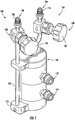
- FIGS. 1-5 illustrate an example embodiment of a solid precursor delivery assembly 100 (e.g., a bubbler assembly, etc.) including one or more aspects of the present disclosure.
- the example assembly 100 is configured ( e.g ., sized, shaped, constructed, etc.) to, among other things, deliver precursor material disposed within the assembly 100 to a reactor site, in gas phase, for subsequent use at the reactor site (e.g., via a carrier gas for subsequent use in a vapor deposition process, etc.). It should be noted that the example assembly 100 may be used with any solid precursor material (e.g.
- TMI trimethylindium
- MgCp 2 bis(cyclopentadienyl)magnesium
- PDMAT pentakis(dimethylamino)tantalum
- M(THD) n Metal beta-Diketonates
- MX 4 Metal halides
- M may include Hafnium (Hf), Zirconium (Zr), etc.
- X may include Chlorine (CI), Bromine (Br), Iodine (I), etc.), Metal cyclopentadienyls ((R n Cp 5-n ) 2 M where R may include methyl groups, ethyl groups, isopropyl groups, tertiarybutyl groups, etc.; M may include Barium (Ba), Strontium (Sr), etc.; and n is 1-3), Metal carbonyls (e.g., Ru3(CO) 12 , W(CO) 6 , etc.) etc.) within the scope of the present disclosure.
- any suitable carrier gas may be used with the example assembly 100, including, for example, nitrogen gas, hydrogen gas, argon gas, carbon monoxide, etc.
- the example solid precursor delivery assembly 100 generally includes a cylindrical container 102 for holding precursor material (and vaporized precursor material), and a valve assembly 104 for controlling, for example, carrier gas flow into the container 102 and vapor product (comprising carrier gas and vaporized precursor material) flow out of the container 102, etc.
- the container 102 can be formed as a generally substantially sealed structure, for example, to inhibit undesired flow of precursor material, vaporized precursor material, carrier gas, vapor product, etc. out of the container 102 and/or to inhibit undesired flow of contaminants, etc. into the container 102.
- the container 102 can be formed from any suitable material within the scope of the present disclosure including, for example, inert materials such as glass, stainless steel, etc. In other example embodiments, containers may have shapes other than cylindrical within the scope of the present disclosure.
- the valve assembly 104 of the illustrated solid precursor delivery assembly 100 generally includes an inlet 106 and an outlet 108.
- the inlet 106 is configured to introduce (or deliver, or dispense, etc.) carrier gas into the container 102
- the outlet 108 is configured to transport (or remove) vaporized precursor material retrieved from the precursor material by the carrier gas out of the container 102.
- the inlet 106 is coupled to an upper portion of the container 102 by a suitable coupling, connection, etc. ( e.g., a threaded coupling, etc.).
- the outlet 108 is coupled to a lower portion of the container 102 by a fluid connector 110. As such, the inlet 106 and the outlet 108 are each in fluid communication with the container 102.
- Carrier gas can thus generally flow from the inlet 106, through the container 102, and to the outlet 108 as desired (e.g., from the upper portion of the container 102 to the lower portion of the container 102, etc.).
- solid precursor delivery assemblies may include inlets coupled to lower portions of containers and outlets coupled to upper portions of the containers such that carrier gas flows generally upwardly through the containers (e.g., from the lower portions of the containers to the upper portions of the containers, etc.).
- first and second fill ports 112 and 114 are positioned along an outer surface portion of the container 102 for use in filling and/or refilling the container 102 as necessary, for example, with precursor material.
- the fill ports 112 and 114 are each coupled to the container 102 by a suitable coupling, connection, etc. such that the fill ports 112 and 114 are each in fluid communication with the container 102.
- the fill ports 112 and 114 may be capped with an appropriate fitting, connector, etc. to help generally seal the container 102 and help ensure that carrier gas flow through the container 102 is from the inlet 106 to the outlet 108 via desired pathways.
- the inlet 106 generally includes a coupling 118 and a valve structure 120.
- the coupling 118 is configured to couple (e.g., via a threaded connection, etc.) the inlet 106 to a carrier gas supply line (not shown) for supplying carrier gas to the inlet 106.
- the valve structure 120 is configured to control the flow of carrier gas into the container 102 through the inlet 106.
- An actuator 122 of the valve structure 120 can be operated to selectively open a valve spool (not shown) to allow the carrier gas to flow into the container 102, and to selectively close the valve spool (not shown) to inhibit the carrier gas from flowing into the container 102.
- the outlet 108 generally includes a coupling 126 and a valve structure 128.
- the coupling 126 is configured to couple ( e.g., via a threaded connection, etc.) the outlet 108 to a product transfer line (not shown) for receiving vapor product out of the container 102 ( e.g., by drawing a vacuum through the product transfer line, etc.).
- the valve structure 128 is configured to control the flow of vapor product out of the container 102 through the outlet 108.
- the outlet 108 also includes an exterior tube 130 extending from the valve structure 128 to the fluid connector 110, substantially along a height (or length) dimension of (and spaced apart from) the container 102.
- the exterior tube 130 may be coupled to the fluid connector 110 by a suitable coupling, connector, etc. (e.g., a threaded coupling, etc.).
- An actuator 132 of the valve structure 128 can be operated to selectively open a valve spool (not shown) to allow the vapor product to flow out of the container 102 ( e.g., through the fluid connector 110 and the exterior tube 130 to the product transfer line, etc.), and to selectively close the valve spool (not shown) to inhibit the vapor product from flowing out of the container 102.
- solid precursor delivery assemblies may include outlets having interior tubes disposed substantially within containers and coupled to the containers at lower portions thereof for use in removing vapor product out of the containers.
- the container 102 of the illustrated solid precursor delivery assembly 100 includes a uniform, generally cylindrical interior space 136 defined therein.
- containers may have interior spaces having shapes other than cylindrical within the scope of the present disclosure.
- the interior space 136 of the container 102 is divided into four chambers 138, 140, 142, and 144 (oriented generally in series) by three porous distributor plates 148, 150, and 152 (broadly, porous dividers).
- the four chambers generally include an inlet chamber 138, first and second precursor chambers 140 and 142, and an outlet chamber 144.
- the inlet chamber 138 is generally configured to receive carrier gas into the container 102 from the inlet 106 and is located toward the upper portion of the container 102, adjacent where the inlet 106 introduces carrier gas into the container 102.
- the outlet chamber 144 is generally configured to transition carrier gas (and vaporized precursor materials recovered by the carrier gas) from the container 102 to the outlet 108 and is located toward the lower portion of the container 102, adjacent where the outlet 108 removes carrier gas from the container 102.
- the first and second precursor chambers 140 and 142 are each configured to hold precursor material within each of the respective chambers 140 and 142.
- the chambers 138, 140, 142, and 144 may have any desired shape, size, etc. within the scope of the present disclosure.
- a first distributor plate 148 is located toward the upper portion of the container 102; a second distributor plate 150 is located generally below the first distributor plate 148 toward a middle portion of the container 102; and a third distributor plate 152 is located generally below the second distributor plate 150 toward a lower portion of the container 102.
- the inlet chamber 138 is defined toward the upper portion of the container 102 generally above the first distributor plate 148; the first precursor chamber 140 is defined generally between the first distributor plate 148 and the second distributor plate 150; the second precursor chamber 142 is defined generally between the second distributor plate 150 and the third distributor plate 152; and the outlet chamber 144 is defined toward the lower portion of the container 102 generally below the third distributor plate 152.
- the distributor plates 148, 150, and 152 are each fixedly coupled (and generally sealed) to an interior surface portion of the container 102 so as to inhibit flow of the carrier gas and vapor product around peripheral edges of the distributor plates 148, 150, and 152 ( e.g., between the peripheral edges of the distributor plates 148, 150, and 152 and the interior surface portion of the container 102, etc).
- the distributor plates 148, 150, and 152 may be welded to the interior surface portion of the container 102, mechanically fastened and sealed to the interior surface portion of the container 102, otherwise sealed to the interior surface portion of the container 102, etc.
- the distributor plates help at least partially define a generally fixed size, volume, etc.
- solid precursor delivery assemblies may have chambers that all have similar sizes, volumes, etc., or chambers that all have different sizes, volumes, etc. This will be described in more detail hereinafter.
- the distributor plates 148, 150, and 152 are each generally configured to create a pressure differential within the container 102 between adjacent chambers 138, 140, 142, and 144.
- the distributor plates 148, 150, and 152 accomplish this by generally resisting flow of carrier gas and/or vaporized precursor material therethrough.
- the distributor plates 148, 150, and 152 effectively control flow of the carrier gas and/or vaporized precursor material through the container 102, and can help provide good distribution of carrier gas through the container 102.
- the distributor plates 148, 150, and 152 may be generally configured to create a pressure differential of about five thousand Pascals.
- the pressure differential across each of the distributor plates 148, 150, and 152 should be significantly larger than the pressure drop across the precursor material, if any, in the respective chamber 138, 140, 142, or 144 immediately upstream of the given distributor plate 148, 150, or 152, for example about ten times larger than the pressure drop across said precursor material, and as large a fraction as practicable of the average pressure in the chamber 138, 140, 142, or 144 upstream of the given distributor plate 148, 150, or 152, for example about 0.5 percent to about 50 percent of said pressure.
- These numerical values are provided as examples, and do not limit the scope of the present disclosure.
- distributor plates having a desired nominal pore sizes (e.g., distributor plates with nominal pore sizes of about 0.5 microns, etc.) may be used; distributor plates having a desired resistance to gas flow ( e.g., greater than about 2 x 10 9 per square meter, etc.) may be used; distributor plates having a desired thickness ( e.g., about 0.125 inches (about 0.316 centimeters), etc.) may be used, distributor plates creating a desired pressure differential there across (e.g., distributor plates creating a pressure differential of about five thousand Pascals for gas flow there across, distributor plates creating a pressure differential of about 23 pounds per square inch of water flow there across, etc.) may be used, etc.
- a desired nominal pore sizes e.g., distributor plates with nominal pore sizes of about 0.5 microns, etc.
- distributor plates having a desired resistance to gas flow e.g., greater than about 2 x 10 9 per square meter, etc.
- distributor plates having a desired thickness e.g., about
- Distributor plates configured to support solid materials thereon, while allowing fluids to flow through (e.g., when a desired pressure differential across the distributor plates are achieved, etc.) may be used. It should be appreciated that the pressure differential created by the distributor plates generally depends on the type of fluid passing through the distributor plates.
- distributor plates formed from any suitable material may be used.
- distributor plates including stainless steel sintered frits, etc. may be used.
- distributor plates that are substantially the same may be used in the example solid precursor delivery assembly 100.
- solid precursor delivery assemblies may include at least one or more distributor plates that are different from at least one or more other distributor plates.
- porous metal distributor plates from Mott Corporation (Farmington, Ct.) may be used (e.g., such distributor plates may have liquid permeability coefficients of about 30, gas permeability coefficients of about 260, etc.).
- the solid precursor delivery assembly 100 includes the three distributor plates 148, 150, and 152 that divide the interior space 136 of the container 102 into the four generally vertically spaced chambers 138, 140, 142, and 144 (and thus generally provide three pressure differentials, or pressure drops within the container 102).
- solid precursor delivery assemblies may include more than or less than three distributor plates and/or may include distributor plates that divide interior spaces of containers into more than or less than four chambers.
- solid precursor delivery assemblies may include distributor plates that divide interior spaces of containers into horizontally spaced chambers.
- solid precursor delivery assemblies may include containers in which precursor material is located within more than two chambers ( e.g., such that the containers include more than two precursor chambers, for example, three precursor chambers, etc.).
- Example operation of the illustrated solid precursor delivery assembly 100 will be described next with continued reference to FIG. 5 .
- precursor material is initially positioned within the first and second precursor chambers 140 and 142 of the container 102. More particularly, precursor material is positioned on an upper portion of the second distributor plate 150 within the first precursor chamber 140 ( e.g., via the first fill port 112, etc.), and precursor material is positioned on an upper portion of the third distributor plate 152 within the second precursor chamber 142 ( e.g., via the second fill port 114, etc.).
- the generally fixed positions of the first and second distributor plates 148 and 150 (which generally define the first precursor chamber 140) may provide for a headspace above the precursor material positioned within the first precursor chamber 140.
- the generally fixed positions of the second and third distributor plates 150 and 152 (which generally define the second precursor chamber 142) may provide for a headspace above the precursor material positioned within the second precursor chamber 142.
- the solid precursor delivery assembly 100 is generally operated under reduced pressure (e.g., a vacuum is drawn at the outlet 108, etc.). As such, a generally lower pressure region exists toward the outlet 108 ( e.g., toward the lower portion of the container 102 in the illustrated embodiment, etc.) and a generally higher pressure region exits toward the inlet 106 ( e.g., toward the upper portion of the container 102 in the illustrated embodiment, etc.). As such, carrier gas will generally flow from the upper portion of the container 102 to the lower portion of the container 102 in the illustrated embodiment.
- reduced pressure e.g., a vacuum is drawn at the outlet 108, etc.
- Carrier gas is introduced into the container 102 of the solid precursor delivery assembly 100 through the inlet 106 of the valve assembly 104 (e.g., via selective operation of the valve structure 120, etc.).
- the carrier gas discharges from the inlet 106 into the inlet chamber 138 of the container 102.
- the first distributor plate 148 resists flow of the carrier gas from the inlet chamber 138 to the first precursor chamber 140, and the carrier gas generally accumulates and fills the inlet chamber 138.
- carrier gas pressure therein increases until a sufficient pressure differential exists across the first distributor plate 148 (e.g., carrier gas pressure in the inlet chamber 138 is sufficiently greater than that in the first precursor chamber 140, etc.) to allow the carrier gas to flow through the first distributor plate 148 ( e.g., through pore openings of the first distributor plate 148, etc.) and into the first precursor chamber 140.
- a sufficient pressure differential exists across the first distributor plate 148 (e.g., carrier gas pressure in the inlet chamber 138 is sufficiently greater than that in the first precursor chamber 140, etc.) to allow the carrier gas to flow through the first distributor plate 148 ( e.g., through pore openings of the first distributor plate 148, etc.) and into the first precursor chamber 140.
- the second distributor plate 150 resists flow of the carrier gas from the first precursor chamber 140 to the second precursor chamber 142.
- the carrier gas generally accumulates and fills the first precursor chamber 140 (including the headspace generally above the precursor material on the upper surface of the second distributor plate 150 within the first precursor chamber 140). This allows the carrier gas to pick up (and become at least partially saturated with) vaporized precursor material.
- Carrier gas (and vaporized precursor material) pressure in the first precursor chamber 140 increases until a sufficient pressure differential exists across the second distributor plate 150 (e.g ., pressure in the first precursor chamber 140 is sufficiently greater than that in the second precursor chamber 142, etc.) to allow the carrier gas and vaporized precursor material to flow steadily through the second distributor plate 150 ( e.g., through the precursor material on the upper surface of the second distributor plate 150 and then through pore openings of the second distributor plate 150, etc.) and into the second precursor chamber 142.
- the pressure differential established across the second distributor plate 150 may be the same as or may be different from the pressure differential established across the first distributor plate 148.
- the third distributor plate 152 resists flow of the carrier gas from the second precursor chamber 142 to the outlet chamber 144.
- the carrier gas generally accumulates and fills the second precursor chamber 142 (including the headspace generally above the precursor material on the upper surface of the third distributor plate 152 within the second precursor chamber 142). This allows the carrier gas to pick up and top off saturation thereof ( e.g., become fully saturated, etc.) with vaporized precursor material from the second precursor chamber 142.
- Pressure in the second precursor chamber 142 increases until a sufficient pressure differential exists across the third distributor plate 152 (e.g., pressure in the second precursor chamber 142 is sufficiently greater than that in the outlet chamber 144, etc.) to allow the carrier gas saturated with vaporized precursor material to flow steadily through the third distributor plate 152 ( e.g., through the precursor material on the upper surface of the third distributor plate 152 and then through pore openings of the third distributor plate 152, etc.) and into the outlet chamber 144. From the outlet chamber 144, the saturated carrier gas (generally saturated with vapor product from the precursor material) exits the container 102 through the outlet 108 (via an opening in the lower portion of the container 102) as desired for subsequent use.
- the pressure differential established across the third distributor plate 152 may be the same as or may be different from the pressure differential established across the first distributor plate 148 and/or the pressure differential established across the second distributor plate 150.
- the illustrated solid precursor delivery assembly 100 generally provides a pathway for carrier gas to flow through the container 102 from the inlet 106 to the inlet chamber 138, through the first distributor plate 148, through the first precursor chamber 140, through the second distributor plate 150, through the second precursor chamber 142, through the third distributor plate 152, and through the outlet chamber 144 to the outlet 108.
- Other pathways of carrier gas flow through the container 102 may be provided within the scope of the present disclosure.
- the multi-chamber configuration of the illustrated solid precursor delivery assembly 100 can help provide consistent saturated carrier gas to the outlet 108 because the carrier gas passes through two chambers (e.g., chambers 140 and 142, etc.) having precursor material before being removed.
- the carrier gas initially flows through the first precursor chamber 140 where it picks up a first amount of vaporized precursor material to become at least partially saturated, and then the carrier gas flows through the second precursor chamber 142 where, the carrier gas can pick up additional vaporized precursor material to top off saturation before it is removed through the outlet 108.
- the multi-chamber configuration of the illustrated solid precursor delivery assembly 100 can help provide more efficient and/or complete depletion of precursor material.
- a larger quantity of precursor material can be placed in the first precursor chamber 140 than the second precursor chamber 142 to account for diminished saturation requirements of the carrier gas as the carrier gas passes from the first precursor chamber 140 to the second precursor chamber 142.
- the carrier gas will generally have a lot of volatilized precursor material in it already after leaving the first precursor chamber 140 so that a saturative topping is only required in the second precursor chamber 142.
- the bulk of vaporized precursor material in the carrier gas leaving the container 102 (through the outlet 108) will be from the first precursor chamber 140, with less being from the second precursor chamber 142.
- first precursor chamber 140 may be filled with about 75 grams of precursor material and the second precursor chamber 142 may be filled with about 25 grams of precursor material.
- solid precursor delivery assemblies may include first precursor chambers sized larger than second precursor chambers to accommodate the larger quantities of precursor material that may be placed in the first precursor chambers.
- solid precursor delivery assemblies may have (but are not limited to) volume ratios of first precursor chambers to second precursor chambers of about 2:1, about 3:1, about 4:1, etc.
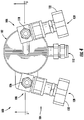
- FIG. 6 illustrates another example embodiment of a solid precursor delivery assembly 200 (e.g., a bubbler assembly, etc.) including one or more aspects of the present disclosure.
- the example assembly 200 of this embodiment is similar to the solid precursor delivery assembly 100 previously described and illustrated in FIGS. 1-5 .
- the illustrated solid precursor delivery assembly 200 generally includes a cylindrical container 202 for holding precursor material (and vaporized precursor material), and a valve assembly 204 for controlling, for example, carrier gas flow into the container 202 and vapor product (comprising carrier gas and vaporized precursor material) flow out of the container 202, etc.
- the container 202 includes a uniform, generally cylindrical interior space 236 defined therein.
- the valve assembly 204 of the illustrated solid precursor delivery assembly 200 generally includes an inlet 206 and an outlet 208.
- the inlet 206 is configured to introduce (or deliver, or dispense, etc.) carrier gas into the container 202.
- the outlet 208 is configured to transport (or remove) vapor product out of the container 202.
- the inlet 206 and the outlet 208 are each coupled to an upper portion of the container 202 by suitable couplings, connections, etc. ( e.g., threaded couplings, etc.).
- the outlet 208 includes an interior tube 230 extending generally through the interior space 236 of the container 202 toward a lower portion of the container 202.
- the inlet 206 and the outlet 208 are each in fluid communication with the container 202.
- Carrier gas can thus generally flow through the illustrated container 202 from the inlet 206 to the outlet 208 (from an upper portion of the container 202 to a lower portion of the container 202).
- Fill ports 212 and 214 are provided for use in filling and/or refilling the container 202 as necessary, for example, with precursor material.
- the fill ports 212 and 214 are each coupled to the container 202 by a suitable coupling, connection, etc. such that the fill ports 212 and 214 are each in fluid communication with the container 202.
- the fill ports 212 and 214 may be capped with an appropriate fitting, connector, etc. to help generally seal the container 202 and help ensure that carrier gas flow through the container 202 is from the inlet 206 to the outlet 208 via desired pathways.
- the interior space 236 of the container 202 is divided into four chambers 238, 240, 242, and 244 (oriented generally in series) by three porous distributor plates 248, 250, and 252 (broadly, porous dividers).
- the four chambers generally include an inlet chamber 238, first and second precursor chambers 240 and 242, and an outlet chamber 244.
- the inlet chamber 238 is generally configured to receive carrier gas into the container 202 from the inlet 206 and is located toward the upper portion of the container 202, adjacent where the inlet 206 introduces carrier gas into the container 202.
- the outlet chamber 244 is generally configured to transition carrier gas (and vaporized precursor materials recovered by the carrier gas) from the container 102 to the outlet 108 and is located toward the lower portion of the container 202, adjacent where the outlet 208 removes carrier gas from the container 202.
- the first and second precursor chambers 240 and 242 are each configured to hold precursor material within the container 202.
- a first distributor plate 248 is located toward an upper portion of the container 202; a second distributor plate 250 is located generally below the first distributor plate 248 toward a middle portion of the container 202; and a third distributor plate 252 is located generally below the second distributor plate 250 toward a lower portion of the container 202.
- the inlet chamber 238 is defined toward the upper portion of the container 202 generally above the first distributor plate 248; the first precursor chamber 240 is defined generally between the first distributor plate 248 and the second distributor plate 250; the second precursor chamber 242 is defined generally between the second distributor plate 250 and the third distributor plate 252; and the outlet chamber 244 is defined toward the lower portion of the container 202 generally below the third distributor plate 252.
- the distributor plates 248, 250, and 252 are each fixedly coupled (and generally sealed) to an interior surface portion of the container 202 so as to inhibit flow of the carrier gas and vapor product around peripheral edges of the distributor plates 248, 250, and 252 (e.g., between the peripheral edges of the distributor plates 248, 250, and 252 and the interior surface portion of the container 202, etc).
- the distributor plates 248, 250, and 252 may be welded to the interior surface portion of the container 202, mechanically fastened and sealed to the interior surface portion of the container 202, otherwise sealed to the interior surface portion of the container 102, etc.
- the interior tube 230 of the outlet 208 as well as tubes 260 of first and second fill ports 212 and 214 extend into the container 202 generally through openings in the distributor plates 248, 250, and 252. Seals may be provided around the tubes 230 and 260 where they pass through the distributor plates 248, 250, and 252 so as to inhibit undesired flow of the carrier gas and vapor product through the distributor plates 248, 250, and 252 at these locations.
- the distributor plates 248, 250, and 252 are each generally configured to create a pressure differential within the container 202 between respective chambers 238, 240, 242, and 244.
- the distributor plates 248, 250, and 252 accomplish this by generally resisting flow of carrier gas and/or vaporized precursor material therethrough until a desired pressure differential is established.
- the distributor plates 248, 250, and 252 effectively control flow of the carrier gas and/or vaporized precursor material through the container 202, and can help provide good distribution of carrier gas through the container 202.
- example solid precursor delivery assemblies of the present disclosure may provide various improvements, advantages, benefits, etc. over prior assemblies.
- distributor plates of the example assemblies generally resist flow of carrier gas (and vaporized precursor material recovered by the carrier gas) between chambers of the containers.
- This provides generally complex flow paths of carrier gas through the containers (e.g., from the inlets, through the distributor plates, and to the outlets, etc.) which increases contact time of the carrier gas with the precursor material within the containers ( e.g., within the chambers of the containers, etc.).
- this causes the carrier gas to generally fill each of the chambers of the containers (and thus the headspaces above the precursor material) before flowing through respective distributor plates.
- this helps to increase carrier gas residence time within each of the chambers (and thus contact time with exposed surfaces of the precursor material within the chambers), homogenize (and/or improve) surface contact of the carrier gas with the precursor material within the chambers, and promote generally uniform flow of the carrier gas through the precursor material.
- consistently saturated carrier gas may be provided to the outlets.
- Distributor plates of the example solid precursor delivery assemblies also have generally uniform constructions. This can help to provide generally uniform resistance to flow of carrier gas through the distributor plates ( e.g., across a surface area of the distributor plates, etc.) and can help to allow the distributor plates to diffuse the carrier gas generally evenly, uniformly, etc. through the precursor material. As a result, undesired channeling and/or maldistribution of carrier gas through the precursor material may be inhibited, and generally uniform depletion of the precursor material may be achieved.
- distributor plates of the example solid precursor delivery assemblies (via their resistance to carrier gas and vapor product flow) generate sequential pressure differentials (e.g., pressure drops, etc.) within the containers.
- pressure differentials e.g., pressure drops, etc.
- relatively high pressure differentials may exits ( e.g., about five thousand Pascals, etc.).
- These pressure differentials in effect, create a pressure gradient across the container (between the inlet and the outlet), with a generally higher pressure at the inlet and a generally lower pressure at the outlet, and in turn help promote generally uniform flow of the carrier gas over the cross sections of the containers ( e.g., generally constant carrier gas mass fluxes transversely through the containers) and through each of the distributor plates. Decreased localized velocities, pressures, etc. of carrier gas (which can cause channeling) may be avoided.
- example solid precursor delivery assemblies of the present disclosure utilize chambered constructions, with precursor material located in each of multiple chambers (e.g., two chambers, etc.).
- this chambered construction can also provide smaller volumes and smaller headspaces as compared to single chamber containers. The smaller volumes and smaller headspaces fill with carrier gas quicker and can thus allow for reduced residence times of the carrier gas within each of the chambers to achieve ultimate saturation.
- Example solid precursor delivery assemblies of the present disclosure may provide a stable, more consistent, saturated vapor of precursor material to a reactor site for a longer period of time (e.g., even as the precursor material becomes depleted, etc.).
- depletion of the precursor material may generally be uniform across a surface area of the precursor material in connection with the illustrated solid precursor delivery assembly, concentration decreases in the vaporized precursor material will occur at later stages of operation, promoting improved usage efficiency of the precursor material. Because most of the vapor product will come uniformly from the precursor material (based on uniform pressure across a surface area of the precursor material), channeling of the precursor material (e.g., at areas of localized decreased pressure, velocity, etc.) may be reduced and/or eliminated.
- substantially all of the precursor material within the container can be effectively used and delivered to the reactor site.
- at least about ninety percent or more of the precursor material can be effectively used and delivered to the reactor site at substantially consistent concentrations.
- at least about ninety-five percent or more of the precursor material can be effectively used and delivered to the reactor site at substantially consistent concentrations.
- a solid precursor delivery assembly includes a generally cylindrical stainless steel container having an outer diameter dimension of the container of about 3.0 inches (about 7.6 centimeters) and an overall height dimension of about 6.15 inches (about 15.6 centimeters).
- An interior, generally cylindrical space of the container includes a diameter dimension of about 2.8 inches (about 7.1 centimeters) and a height dimension of about 5.1 inches (about 12.9 centimeters), and thus defines a volume of about 31.4 cubic inches (about 515 cubic centimeters).
- This example assembly also includes three stainless steel sintered discs oriented generally parallel within the stainless steel container and welded to an interior surface portion of the stainless steel container.
- Each of the stainless steel sintered discs includes a thickness of about 0.125 inches (about 0.316 centimeters), and each includes pores with a nominal pore size of about 0.5 microns.
- each of the stainless steel sintered discs configured to create a pressure differential there across (as measured by water flow) of about 23 pounds per square inch.
- the stainless steel sintered discs define four chambers within the stainless steel container of this example assembly, including an inlet chamber, an outlet chamber, and two precursor chambers.
- the inlet chamber and the outlet chamber each have a height dimension of about 0.4 inches (about 1.0 centimeters) and each have a volume of about 6.15 cubic inches (about 100.8 cubic centimeters).
- the first precursor chamber has a height dimension of about 1.94 inches (about 4.9 centimeters) and a volume of about 11.9 cubic inches (about 195 cubic centimeters), and the second precursor chamber has a height dimension of about 1.91 inches (about 4.8 centimeters) and a volume of about 11.8 cubic inches (about 193.4 cubic centimeters).
- example solid precursor delivery assemblies of the present disclosure may accommodate any desired mass of precursor material, for example, 350 grams, 850 grams, or any mass other than 350 grams and 850 grams within the scope of the present disclosure.
- the example solid precursor delivery assembly 100 illustrated in FIGS. 1-5 was operated for about one hour with 100 grams of the precursor material trimethylindium (TMI) disposed within each of the first and second precursor chambers 140 and 142.
- the assembly 100 was maintained at a temperature of about 17 degrees Celsius during operation while a carrier gas was flowed therethrough at a generally constant rate of about 800 standard cubic centimeters per minute.
- a generally constant pressure of about 370 Torr existed just before the inlet 106 of the assembly 100, and a generally constant pressure of about 225 Torr was maintained at the outlet 108 of the assembly 100.
- the carrier gas (saturated with TMI) leaving the assembly 100 was passed through an ultrasonic concentration measurement system to determine accurately the TMI concentration within the carrier gas.
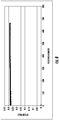
- These results are shown in FIG. 7 as Epison amounts/values of TMI over time for the operation of the assembly 100 (one reading was taken every two seconds during operation of the assembly 100).
- FIG. 7 indicates generally consistent concentration readings of TMI within the carrier gas leaving the assembly 100 over the example prolonged period of operation, highlighting the effectiveness of the given assembly 100 (and output stability).
- the example solid precursor delivery assembly 100 illustrated in FIGS. 1-5 was operated for about twenty minutes with 100 grams of the precursor material trimethylindium (TMI) disposed within each of the first and second precursor chambers 140 and 142.
- the assembly 100 was maintained at a temperature of about 17 degrees Celsius during operation while a carrier gas was flowed therethrough at a generally constant rate of about 800 standard cubic centimeters per minute.
- a generally constant pressure of about 370 Torr existed just before the inlet 106 of the assembly 100, and a generally constant pressure of about 225 Torr was maintained at the outlet 108 of the assembly 100.
- the carrier gas (saturated with TMI) leaving the assembly 100 was passed through an ultrasonic concentration measurement system to determine accurately the TMI concentration within the carrier gas.
- These results are shown in FIG. 8 as Epison amounts/values of TMI over time for the operation of the assembly 100 (one reading was taken every two seconds during operation of the assembly 100).
- FIG. 8 again indicates generally consistent concentration readings of TMI within the carrier gas leaving the assembly 100 over the example prolonged period of operation, highlighting the effectiveness of the given assembly 100 (and output stability).
Landscapes
- Chemical & Material Sciences (AREA)
- Engineering & Computer Science (AREA)
- Chemical Kinetics & Catalysis (AREA)
- Materials Engineering (AREA)
- Mechanical Engineering (AREA)
- Metallurgy (AREA)
- Organic Chemistry (AREA)
- General Chemical & Material Sciences (AREA)
- Physics & Mathematics (AREA)
- Condensed Matter Physics & Semiconductors (AREA)
- General Physics & Mathematics (AREA)
- Manufacturing & Machinery (AREA)
- Computer Hardware Design (AREA)
- Microelectronics & Electronic Packaging (AREA)
- Power Engineering (AREA)
- Chemical Vapour Deposition (AREA)
Claims (10)
- Un procédé de récupération d'un matériau précurseur vaporisé avec un gaz porteur dans un ensemble de distribution de précurseur solide à plusieurs chambres (100, 200), le procédé comprenant :la fourniture d'un gaz porteur à un ensemble de distribution de précurseur solide à plusieurs chambres (100, 200) ;retenir un gaz porteur dans l'espace libre d'une première chambre de précurseur (140, 240) de l'ensemble de distribution de précurseur solide à plusieurs chambres (100, 200) généralement au-dessus du matériau précurseur disposé à l'intérieur de la première chambre de précurseur (140, 240) jusqu'à ce que une différence de pression d'environ 0,5 pour cent à environ 50 pour cent de la pression moyenne dans la première chambre de précurseur (140, 240) existe à travers une première plaque de distribution poreuse (150, 250) de l'ensemble de distribution de précurseur solide à plusieurs chambres (100, 200) séparant la premier chambre de précurseur (140, 240) à partir d'une deuxième chambre de précurseur (142, 242), moment auquel le gaz porteur et le matériau précurseur vaporisé récupéré par le gaz porteur s'écoulent à travers la première plaque de distribution poreuse (150, 250) vers la deuxième chambre de précurseur (142, 242) ;retenir le gaz porteur dans l'espace libre de la deuxième chambre de précurseur (142, 242) de l'ensemble de distribution de précurseur solide à plusieurs chambres (100, 200) généralement au-dessus du matériau précurseur disposé à l'intérieur de la deuxième chambre de précurseur (142, 242) jusqu'à ce que une différence de pression d'environ 0,5 pour cent à environ 50 pour cent de la pression moyenne dans la deuxième chambre de précurseur (142, 242) existe à travers une deuxième plaque de distribution poreuse (152, 252) de l'ensemble de distribution de précurseur solide à plusieurs chambres (100, 200) séparant la deuxième chambre de précurseur (142, 242) à partir d'une troisième chambre, moment auquel le gaz porteur et le matériau précurseur vaporisé récupéré par le gaz porteur s'écoulent à travers la deuxième plaque de distribution poreuse (152, 252) vers la troisième chambre ; etl'élimination du gaz porteur et du matériau précurseur vaporisé récupéré par le gaz porteur à partir de l'ensemble de distribution de précurseur solide à plusieurs chambres (100, 200).
- Le procédé selon la revendication 1, dans lequel la troisième chambre est une chambre de sortie (144, 244).
- Le procédé selon la revendication 2, dans lequel l'élimination du gaz porteur et du matériau précurseur vaporisé à partir de l'ensemble de distribution de précurseur solide à plusieurs chambres (100, 200) comprend l'élimination du gaz porteur et du matériau précurseur vaporisé à partir de la chambre de sortie (144, 244) via une sortie (108, 208) de l'ensemble de distribution de précurseur solide à plusieurs chambres (100, 200).
- Le procédé selon la revendication 3, dans lequel la fourniture du gaz porteur à l'ensemble de distribution de précurseur solide à plusieurs chambres (100, 200) comprend la fourniture du gaz porteur à une chambre d'entrée (138, 238) de l'ensemble de distribution de précurseur solide à plusieurs chambres (100, 200) via une entrée (106, 206) de l'ensemble de distribution de précurseur solide à plusieurs chambres (100, 200).
- Le procédé selon la revendication 4, comprenant en outre la rétention du gaz porteur, fourni à la chambre d'entrée (138, 238), à l'intérieur de la chambre d'entrée (138, 238) jusqu'à ce que une différence de pression d'environ 0,5 pour cent à environ 50 pour cent de la pression moyenne dans la chambre d'entrée (138, 238) existe à travers une troisième plaque de distribution poreuse (148, 248) de l'ensemble de distribution de précurseur solide à plusieurs chambres (100, 200) séparant la chambre d'entrée (138, 238) à partir de la première chambre de précurseur (140, 240), moment auquel le gaz porteur s'écoule à travers la troisième plaque de distribution poreuse (148, 248) vers la première chambre de précurseur (140, 240).
- Le procédé selon la revendication 5, dans lequel la chambre d'entrée (138, 238), la première chambre de précurseur (140, 240), la deuxième chambre de précurseur (142, 242), et la chambre de sortie (144, 244) sont définies dans un récipient (102, 202) de l'ensemble de distribution de précurseur solide à plusieurs chambres (100, 200) ; et dans lequel la première plaque de distribution poreuse (150, 250), la deuxième plaque de distribution poreuse (152, 252), et la troisième plaque de distribution poreuse (148, 248) sont chacune couplées de manière fixe à une surface intérieure du récipient (102, 202).
- Le procédé selon la revendication 6, dans lequel le récipient (102, 202) comprend une partie supérieure, l'entrée (106, 206) étant couplée à la partie supérieure du récipient (102, 202) ; et / ou dans lequel le récipient (102, 202) comprend une partie inférieure, la sortie (108, 208) étant couplée à la partie inférieure du récipient (102, 202).
- Le procédé selon la revendication 1, comprenant en outre le remplissage et / ou la recharge de la première chambre de précurseur (140, 240) avec un matériau précurseur via un premier orifice de remplissage; et / ou remplir et / ou recharger la deuxième chambre de précurseur (142, 242) avec un matériau précurseur via un deuxième orifice de remplissage.
- Le procédé selon la revendication 1, dans lequel un volume de la première chambre de précurseur (140, 240) est supérieur à un volume de la deuxième chambre de précurseur (142, 242).
- Le procédé selon la revendication 1, dans lequel les première et deuxième plaques de distribution poreuses (150, 152, 250, 252) ont chacune des ouvertures de pore avec des tailles de pore d'environ 0,5 micron.
Priority Applications (1)
| Application Number | Priority Date | Filing Date | Title |
|---|---|---|---|
| EP21188679.1A EP3922751A1 (fr) | 2009-11-02 | 2010-10-21 | Ensembles d'administration de précurseur solide et procédés associés |
Applications Claiming Priority (2)
| Application Number | Priority Date | Filing Date | Title |
|---|---|---|---|
| US25737909P | 2009-11-02 | 2009-11-02 | |
| PCT/US2010/053557 WO2011053505A1 (fr) | 2009-11-02 | 2010-10-21 | Évaporateur |
Related Child Applications (1)
| Application Number | Title | Priority Date | Filing Date |
|---|---|---|---|
| EP21188679.1A Division EP3922751A1 (fr) | 2009-11-02 | 2010-10-21 | Ensembles d'administration de précurseur solide et procédés associés |
Publications (2)
| Publication Number | Publication Date |
|---|---|
| EP2496733A1 EP2496733A1 (fr) | 2012-09-12 |
| EP2496733B1 true EP2496733B1 (fr) | 2021-08-04 |
Family
ID=43430631
Family Applications (2)
| Application Number | Title | Priority Date | Filing Date |
|---|---|---|---|
| EP10775984.7A Active EP2496733B1 (fr) | 2009-11-02 | 2010-10-21 | Procédé d'évaporation |
| EP21188679.1A Pending EP3922751A1 (fr) | 2009-11-02 | 2010-10-21 | Ensembles d'administration de précurseur solide et procédés associés |
Family Applications After (1)
| Application Number | Title | Priority Date | Filing Date |
|---|---|---|---|
| EP21188679.1A Pending EP3922751A1 (fr) | 2009-11-02 | 2010-10-21 | Ensembles d'administration de précurseur solide et procédés associés |
Country Status (8)
| Country | Link |
|---|---|
| US (1) | US9297071B2 (fr) |
| EP (2) | EP2496733B1 (fr) |
| JP (1) | JP5898624B2 (fr) |
| KR (1) | KR101765734B1 (fr) |
| CN (1) | CN102597310B (fr) |
| IL (1) | IL219085A (fr) |
| TW (1) | TWI550127B (fr) |
| WO (1) | WO2011053505A1 (fr) |
Families Citing this family (19)
| Publication number | Priority date | Publication date | Assignee | Title |
|---|---|---|---|---|
| TWI382987B (zh) | 2007-07-24 | 2013-01-21 | Sigma Aldrich Co | 應用於化學相沉積製程的有機金屬前驅物 |
| TWI425110B (zh) | 2007-07-24 | 2014-02-01 | Sigma Aldrich Co | 以化學相沉積法製造含金屬薄膜之方法 |
| TWI467045B (zh) | 2008-05-23 | 2015-01-01 | Sigma Aldrich Co | 高介電常數電介質薄膜與使用鈰基前驅物製造高介電常數電介質薄膜之方法 |
| CN102177374B (zh) * | 2008-08-18 | 2013-06-19 | 西格玛-奥吉奇公司 | 阀组件 |
| CN102574884B (zh) | 2009-08-07 | 2016-02-10 | 西格玛-奥吉奇有限责任公司 | 高分子量烷基-烯丙基三羰基钴配合物及其用于制备介电薄膜的用途 |
| EP2496733B1 (fr) | 2009-11-02 | 2021-08-04 | Sigma-Aldrich Co. LLC | Procédé d'évaporation |
| JP2012248803A (ja) * | 2011-05-31 | 2012-12-13 | Hitachi Cable Ltd | 金属塩化物ガスの発生装置および金属塩化物ガスの発生方法、並びに、ハイドライド気相成長装置、窒化物半導体ウエハ、窒化物半導体デバイス、窒化物半導体発光ダイオード用ウエハ、窒化物半導体自立基板の製造方法および窒化物半導体結晶 |
| US8927748B2 (en) | 2011-08-12 | 2015-01-06 | Sigma-Aldrich Co. Llc | Alkyl-substituted allyl carbonyl metal complexes and use thereof for preparing dielectric thin films |
| US20130269613A1 (en) * | 2012-03-30 | 2013-10-17 | Applied Materials, Inc. | Methods and apparatus for generating and delivering a process gas for processing a substrate |
| US9598766B2 (en) | 2012-05-27 | 2017-03-21 | Air Products And Chemicals, Inc. | Vessel with filter |
| US10392700B2 (en) * | 2014-04-21 | 2019-08-27 | Entegris, Inc. | Solid vaporizer |
| US10443128B2 (en) | 2015-04-18 | 2019-10-15 | Versum Materials Us, Llc | Vessel and method for delivery of precursor materials |
| US10480070B2 (en) * | 2016-05-12 | 2019-11-19 | Versum Materials Us, Llc | Delivery container with flow distributor |
| KR102344996B1 (ko) * | 2017-08-18 | 2021-12-30 | 삼성전자주식회사 | 전구체 공급 유닛, 기판 처리 장치 및 그를 이용한 반도체 소자의 제조방법 |
| US10895347B2 (en) | 2017-10-20 | 2021-01-19 | Entegris, Inc. | Heat transfer to ampoule trays |
| JP6887688B2 (ja) | 2019-02-07 | 2021-06-16 | 株式会社高純度化学研究所 | 蒸発原料用容器、及びその蒸発原料用容器を用いた固体気化供給システム |
| JP6901153B2 (ja) * | 2019-02-07 | 2021-07-14 | 株式会社高純度化学研究所 | 薄膜形成用金属ハロゲン化合物の固体気化供給システム。 |
| US11834740B2 (en) * | 2020-11-10 | 2023-12-05 | Applied Materials, Inc. | Apparatus, system, and method for generating gas for use in a process chamber |
| FI130131B (en) * | 2021-09-07 | 2023-03-09 | Picosun Oy | Precursor container |
Citations (1)
| Publication number | Priority date | Publication date | Assignee | Title |
|---|---|---|---|---|
| JPH08279497A (ja) * | 1995-04-07 | 1996-10-22 | Hitachi Ltd | 半導体製造装置および半導体装置 |
Family Cites Families (170)
| Publication number | Priority date | Publication date | Assignee | Title |
|---|---|---|---|---|
| US1541853A (en) | 1919-06-09 | 1925-06-16 | Westinghouse Electric & Mfg Co | Absorption bulb |
| US1372328A (en) | 1920-03-29 | 1921-03-22 | Adams Fred | Dispensing container or bottle |
| US2076262A (en) | 1933-04-12 | 1937-04-06 | Howe Fiaber H | Apparatus for cleaning receptacles |
| US2032095A (en) | 1935-04-08 | 1936-02-25 | Eugene A O'leary | Apparatus for dispensing liquids |
| US2070517A (en) | 1936-03-25 | 1937-02-09 | Arthur E O Leary | Apparatus for dispensing liquids |
| US2504009A (en) | 1946-07-27 | 1950-04-11 | Phillips De | Agitating and dispensing unit |
| US2738762A (en) | 1951-10-08 | 1956-03-20 | Ohio Commw Eng Co | Apparatus for the deposition of nonconductive copper coatings from vapor phase |
| US3230245A (en) | 1961-08-31 | 1966-01-18 | Standard Oil Co | Recovery of alkyl borate from methanol-alkyl borate mixtures |
| FR1458099A (fr) | 1965-01-08 | 1966-03-04 | Perfectionnements aux dispositifs doseurs | |
| US3338761A (en) | 1965-03-31 | 1967-08-29 | Texas Instruments Inc | Method and apparatus for making compound materials |
| GB1277025A (en) | 1968-09-23 | 1972-06-07 | British Insulated Callenders | Improvements in or relating to apparatus for applying powder to an elongate article |
| US3628339A (en) | 1970-01-27 | 1971-12-21 | Beckman Instruments Inc | Fluid sample stream conditioning |
| US3756068A (en) | 1971-04-30 | 1973-09-04 | Us Army | Carbon dioxide concentration sensor |
| US3831069A (en) | 1972-11-03 | 1974-08-20 | Robertshaw Controls Co | Miniature capacitance level detector |
| US3935740A (en) | 1974-06-20 | 1976-02-03 | Sybron Corporation | Liquid level probe |
| US3884819A (en) | 1974-08-19 | 1975-05-20 | Ozone Inc | Gas cooling and drying system for corona discharge ozone generating unit |
| US4010650A (en) | 1974-12-26 | 1977-03-08 | Ford Motor Company | Apparatus for generating an electrical signal indicative of liquid level |
| US4298037A (en) | 1976-12-02 | 1981-11-03 | J. C. Schumacher Co. | Method of shipping and using semiconductor liquid source materials |
| US4099939A (en) | 1977-07-20 | 1978-07-11 | Mine Safety Appliances Company | Spill-proof gas sampler |
| US4140735A (en) | 1977-08-15 | 1979-02-20 | J. C. Schumacher Co. | Process and apparatus for bubbling gas through a high purity liquid |
| US4211748A (en) | 1978-01-23 | 1980-07-08 | International Telephone And Telegraph Corporation | Stack gas analyzer and thermal oxidation device therefor |
| US4325911A (en) | 1978-01-23 | 1982-04-20 | International Telephone And Telegraph Corporation | Stack gas analyzer and thermal oxidation device therefor |
| WO1980000010A1 (fr) | 1978-06-05 | 1980-01-10 | R Schlenker | Methode de separation isotopique |
| US4191541A (en) | 1978-08-14 | 1980-03-04 | Container Corporation Of America | Method and apparatus for gas sample analysis |
| US4293009A (en) | 1978-09-12 | 1981-10-06 | Fulton Hugh C | Pressurized gas filling head |
| US4224828A (en) | 1978-12-04 | 1980-09-30 | The United States Of America As Represented By The Secretary Of The Army | Non-spill gas-liquid contact unit |
| DE3029352C2 (de) | 1980-08-01 | 1982-12-23 | Endress U. Hauser Gmbh U. Co, 7867 Maulburg | Kapazitive Füllstandsmeßanordnung mit einer stabförmigen Sonde für die Messung des Füllstandes in einem Behälter |
| US4448072A (en) | 1982-02-03 | 1984-05-15 | Tward 2001 Limited | Fluid level measuring system |
| SU1126315A1 (ru) | 1983-05-20 | 1984-11-30 | Гродненское Ордена Дружбы Народов Производственное Объединение "Азот" Им.С.О.Притыцкого | Барботер дл реакционных аппаратов |
| JPS6070176A (ja) * | 1983-09-27 | 1985-04-20 | Fujitsu Ltd | 固体ソ−ス蒸発ボンベ |
| JPS6070176U (ja) | 1983-10-19 | 1985-05-17 | ワイケイケイ株式会社 | 障子戸の外れ止め装置 |
| JPS60131973U (ja) | 1984-02-14 | 1985-09-03 | 古河電気工業株式会社 | 多心丸形ケ−ブルのフラツト端末部 |
| FR2569207B1 (fr) | 1984-08-14 | 1986-11-14 | Mellet Robert | Procede et dispositif d'obtention d'un courant gazeux contenant un compose a l'etat de vapeur, utilisable notamment pour introduire ce compose dans un reacteur d'epitaxie |
| US4645524A (en) | 1985-04-22 | 1987-02-24 | Corning Glass Works | Method for making sodium-containing glass |
| DE3520795A1 (de) | 1985-06-11 | 1986-12-11 | Merck Patent Gmbh, 6100 Darmstadt | Ventil fuer chemikalienbehaelter |
| US4859375A (en) | 1986-12-29 | 1989-08-22 | Air Products And Chemicals, Inc. | Chemical refill system |
| US4919304A (en) | 1985-08-01 | 1990-04-24 | American Cyanamid Company | Bubbler cylinder device |
| US4966207A (en) | 1986-12-29 | 1990-10-30 | Air Products And Chemicals, Inc. | Disposable chemical container |
| DE3702923A1 (de) | 1987-01-31 | 1988-08-11 | Philips Patentverwaltung | Vorrichtung zum anreichern eines traegergases mit dem dampf eines wenig fluechtigen stoffes |
| US4738693A (en) | 1987-04-27 | 1988-04-19 | Advanced Technology Materials, Inc. | Valve block and container for semiconductor source reagent dispensing and/or purification |
| US5031068A (en) | 1987-11-06 | 1991-07-09 | Hansen Technologies Corporation | Liquid level control system for refrigeration apparatus |
| US4809129A (en) | 1987-11-06 | 1989-02-28 | Hansen Technologies Corporation | Liquid level control system for refrigeration apparatus |
| JPH01168331A (ja) | 1987-12-24 | 1989-07-03 | Mitsui Toatsu Chem Inc | 有機金属化合物の飽和方法 |
| DE3801147A1 (de) * | 1988-01-16 | 1989-07-27 | Philips Patentverwaltung | Vorrichtung zum erzeugen eines mit dem dampf eines wenig fluechtigen stoffes angereicherten gasstroms |
| US4886178A (en) | 1988-04-27 | 1989-12-12 | Air Products And Chemicals, Inc. | Method and apparatus for packaging, shipping and using poisonous liquids |
| JPH0269389A (ja) | 1988-08-31 | 1990-03-08 | Toyo Stauffer Chem Co | 有機金属気相成長法における固体有機金属化合物の飽和蒸気生成方法 |
| JPH02172889A (ja) * | 1988-12-26 | 1990-07-04 | Nippon Mining Co Ltd | 気相成長用シリンダー |
| DE3900069A1 (de) | 1989-01-03 | 1990-07-05 | Metallgesellschaft Ag | Verfahren zur gewinnung von elementarem schwefel aus elementaren schwefel enthaltendem material |
| US4915880A (en) | 1989-05-22 | 1990-04-10 | Advanced Delivery & Chemical Systems Incorporated | Container for a bubbler |
| SU1669524A1 (ru) | 1989-07-24 | 1991-08-15 | Ярославский политехнический институт | Смеситель барботажного типа |
| SG45405A1 (en) | 1989-09-26 | 1998-01-16 | Canon Kk | Gas feeding device and deposition film forming apparatus employing the same |
| JPH03131018A (ja) | 1989-10-17 | 1991-06-04 | Victor Co Of Japan Ltd | 固体有機金属材料供給方法及び供給用容器 |
| JPH0692558A (ja) | 1990-09-28 | 1994-04-05 | Otis Elevator Co | 発進時の揺れ及び過剰加速を低減するエレベータの発進制御装置 |
| US5078922A (en) | 1990-10-22 | 1992-01-07 | Watkins-Johnson Company | Liquid source bubbler |
| US5262130A (en) | 1990-12-07 | 1993-11-16 | Baker Hughes Inc. | Fixed bed chemical reactor |
| US5693017A (en) | 1991-02-14 | 1997-12-02 | Wayne State University | Apparatus and method of delivery of gas-supersaturated solutions to a delivery site |
| JP3075295B2 (ja) | 1991-04-19 | 2000-08-14 | オリンパス光学工業株式会社 | 内視鏡 |
| US5199603A (en) | 1991-11-26 | 1993-04-06 | Prescott Norman F | Delivery system for organometallic compounds |
| US5217904A (en) | 1992-01-10 | 1993-06-08 | The United States Of America As Represented By The Secretary Of The Department Of Commerce | Apparatus and method for evaporative concentration of a liquid sample |
| US5235112A (en) | 1992-05-29 | 1993-08-10 | Exxon Chemical Patents Inc. | Stripper-reactor for volatile cobalt recovery |
| RU2045999C1 (ru) | 1992-07-03 | 1995-10-20 | Северо-Кавказский горно-металлургический институт | Ротационный барботер |
| JPH0670176A (ja) * | 1992-08-20 | 1994-03-11 | Canon Inc | 符号化方法および符号装置 |
| JP2000252269A (ja) | 1992-09-21 | 2000-09-14 | Mitsubishi Electric Corp | 液体気化装置及び液体気化方法 |
| AU668538B2 (en) | 1993-01-25 | 1996-05-09 | Kirin Beer Kabushiki Kaisha | Dispenser head for soft drink and cleaning device for soft drink pouring system |
| US5964254A (en) | 1997-07-11 | 1999-10-12 | Advanced Delivery & Chemical Systems, Ltd. | Delivery system and manifold |
| US6029717A (en) | 1993-04-28 | 2000-02-29 | Advanced Delivery & Chemical Systems, Ltd. | High aspect ratio containers for ultrahigh purity chemicals |
| US5878793A (en) | 1993-04-28 | 1999-03-09 | Siegele; Stephen H. | Refillable ampule and method re same |
| US5397467A (en) | 1993-08-12 | 1995-03-14 | Kontes Glass Company | Liquid chromatography system and reservoir cap for use therein |
| US5481197A (en) | 1993-09-17 | 1996-01-02 | Penberthy, Inc. | High pressure, leak resistant explosionproof capacitance probe |
| JPH07211646A (ja) | 1994-01-14 | 1995-08-11 | Mitsubishi Electric Corp | 材料供給装置 |
| WO1995034370A1 (fr) | 1994-06-13 | 1995-12-21 | Chiyoda Corporation | Tube de dispersion gazeuse pour barbotage de gaz dans liquide, procede de barbotage gaz dans liquide et dispositif utilisant ce procede |
| JP2996101B2 (ja) | 1994-08-05 | 1999-12-27 | 信越半導体株式会社 | 液体原料ガスの供給方法および装置 |
| KR960010901A (ko) | 1994-09-30 | 1996-04-20 | 김광호 | 고체 유기화합물 전용 버블러 장치 |
| SE505324C2 (sv) | 1994-11-14 | 1997-08-04 | Gems Pet Systems Ab | Framställning av 11C-metyljodid |
| JPH0940489A (ja) | 1995-03-30 | 1997-02-10 | Pioneer Electron Corp | Mocvdの固体原料供給方法及び供給装置 |
| US5653813A (en) | 1995-04-03 | 1997-08-05 | Novellus Systems, Inc. | Cyclone evaporator |
| US5553395A (en) | 1995-05-31 | 1996-09-10 | Hughes Aircraft Company | Bubbler for solid metal organic source material and method of producing saturated carrying gas |
| MY112219A (en) | 1995-07-27 | 2001-04-30 | Toshiba Kk | Cathode ray tube and manufacturing method therefor |
| US5701084A (en) | 1995-09-22 | 1997-12-23 | Magnetrol International, Inc. | Insulated capacitance probe |
| US5607581A (en) | 1995-10-31 | 1997-03-04 | Systec, Inc. | Debubbling and priming system for chromotography |
| US5749500A (en) | 1996-04-23 | 1998-05-12 | Kraus; Joey | Liquid retrieving adaptor for cylindrical containers |
| US5806573A (en) | 1996-08-13 | 1998-09-15 | Argonaut Technologies Incorporated | Closure device and method for venting, cannulating and pressurizing a vessel |
| US5835678A (en) | 1996-10-03 | 1998-11-10 | Emcore Corporation | Liquid vaporizer system and method |
| JPH10135315A (ja) | 1996-10-29 | 1998-05-22 | Tokyo Electron Ltd | 試料載置台の温度制御装置及び検査装置 |
| EP0953064B1 (fr) | 1996-12-17 | 2007-09-12 | Advanced Technology Materials, Inc. | Recipient d'alimentation en reactif pour le depot chimique en phase vapeur |
| US6148681A (en) | 1997-01-06 | 2000-11-21 | Rosemount Inc. | Level probe with modular connection |
| JPH10223540A (ja) | 1997-02-03 | 1998-08-21 | Sony Corp | 有機金属気相成長装置 |
| JPH1172426A (ja) | 1997-08-29 | 1999-03-16 | Kett Electric Lab | 試料を加熱により気化させる加熱装置 |
| US6078729A (en) | 1997-10-21 | 2000-06-20 | National Environmental Products Ltd., Inc. | Foam, drain and fill control system for humidifier |
| US6053984A (en) | 1997-11-17 | 2000-04-25 | Petvai; Steve I. | Method and apparatus for decomposition of silicon oxide layers for impurity analysis of silicon wafers |
| US5992830A (en) | 1997-12-15 | 1999-11-30 | Olin Corporation | High pressure quartz glass bubbler |
| US6039809A (en) | 1998-01-27 | 2000-03-21 | Mitsubishi Materials Silicon Corporation | Method and apparatus for feeding a gas for epitaxial growth |
| DE19803740C2 (de) | 1998-01-30 | 2001-05-31 | Mtu Aero Engines Gmbh | Gasphasenbeschichtungsverfahren und Vorrichtung zur Gasphasenbeschichtung von Werkstücken |
| US6101816A (en) | 1998-04-28 | 2000-08-15 | Advanced Technology Materials, Inc. | Fluid storage and dispensing system |
| GB9816720D0 (en) | 1998-08-01 | 1998-09-30 | Pilkington Plc | Process for coating glass |
| US5996653A (en) | 1998-10-08 | 1999-12-07 | Eastman Kodak Company | Valve assembly and apparatus |
| JP2000128181A (ja) | 1998-10-26 | 2000-05-09 | Applied Materials Inc | 液体貯蔵容器および液体残量検知方法 |
| IL150315A (en) | 1998-11-30 | 2010-12-30 | Air Prod & Chem | Ultrasonic level sense in a chemical refill system |
| US6257446B1 (en) | 1999-02-18 | 2001-07-10 | Advanced Micro Devices, Inc. | Liquid chemical container with integrated fluid reservoir |
| US7423750B2 (en) | 2001-11-29 | 2008-09-09 | Applera Corporation | Configurations, systems, and methods for optical scanning with at least one first relative angular motion and at least one second angular motion or at least one linear motion |
| US6444038B1 (en) | 1999-12-27 | 2002-09-03 | Morton International, Inc. | Dual fritted bubbler |
| JP3909792B2 (ja) | 1999-08-20 | 2007-04-25 | パイオニア株式会社 | 化学気相成長法における原料供給装置及び原料供給方法 |
| WO2001029491A1 (fr) | 1999-10-16 | 2001-04-26 | Molinar Limited | Systemes de transfert de chaleur ameliores et nouvelles mises en application de ces systemes |
| GB9929279D0 (en) | 1999-12-11 | 2000-02-02 | Epichem Ltd | An improved method of and apparatus for the delivery of precursors in the vapour phase to a plurality of epitaxial reactor sites |
| US6599484B1 (en) | 2000-05-12 | 2003-07-29 | Cti, Inc. | Apparatus for processing radionuclides |
| EP1160355B1 (fr) | 2000-05-31 | 2004-10-27 | Shipley Company LLC | Vaporisateur |
| GB0017968D0 (en) | 2000-07-22 | 2000-09-13 | Epichem Ltd | An improved process and apparatus for the isolation of pure,or substantially pure,organometallic compounds |
| WO2002012780A1 (fr) | 2000-08-04 | 2002-02-14 | Arch Specialty Chemicals, Inc. | Systeme de remplissage automatique de produits chimiques ultra purs ou sensibles a la contamination |
| US6341615B1 (en) | 2000-09-13 | 2002-01-29 | Air Products And Chemicals, Inc. | Self-cleaning vacuum purge system |
| DE10048759A1 (de) | 2000-09-29 | 2002-04-11 | Aixtron Gmbh | Verfahren und Vorrichtung zum Abscheiden insbesondere organischer Schichten im Wege der OVPD |
| US6428847B1 (en) | 2000-10-16 | 2002-08-06 | Primaxx, Inc. | Vortex based CVD reactor |
| US6401463B1 (en) | 2000-11-29 | 2002-06-11 | Marconi Communications, Inc. | Cooling and heating system for an equipment enclosure using a vortex tube |
| US6637212B2 (en) | 2001-04-27 | 2003-10-28 | Matheson Tri-Gas | Method and apparatus for the delivery of liquefied gases having constant impurity levels |
| US6718126B2 (en) | 2001-09-14 | 2004-04-06 | Applied Materials, Inc. | Apparatus and method for vaporizing solid precursor for CVD or atomic layer deposition |
| JP2003166700A (ja) | 2001-11-30 | 2003-06-13 | Nippon Sanso Corp | 減圧機能付き容器弁 |
| TW200300701A (en) | 2001-11-30 | 2003-06-16 | Asml Us Inc | High flow rate bubbler system and method |
| US6986814B2 (en) | 2001-12-20 | 2006-01-17 | General Electric Company | Gas distributor for vapor coating method and container |
| JP2003273093A (ja) | 2002-03-12 | 2003-09-26 | Canon Inc | 固体有機金属の供給方法及びその供給装置 |
| EP1492887A1 (fr) | 2002-04-11 | 2005-01-05 | Sequenom, Inc. | Techniques et dispositifs permettant de realiser des reactions chimiques sur un support solide |
| US7601225B2 (en) | 2002-06-17 | 2009-10-13 | Asm International N.V. | System for controlling the sublimation of reactants |
| KR20040000689A (ko) | 2002-06-25 | 2004-01-07 | 삼성전자주식회사 | 화학기상 증착공정의 원료물질 공급장치 |
| US7186385B2 (en) | 2002-07-17 | 2007-03-06 | Applied Materials, Inc. | Apparatus for providing gas to a processing chamber |
| AU2003250381A1 (en) | 2002-07-17 | 2004-02-02 | Epichem Limited | A method and apparatus for monitoring liquid levels within a vessel |
| GB0216502D0 (en) | 2002-07-17 | 2002-08-28 | Epichem Ltd | A method and apparatus for monitoring liquid levels within a vessel |
| US7077388B2 (en) | 2002-07-19 | 2006-07-18 | Asm America, Inc. | Bubbler for substrate processing |
| US6921062B2 (en) | 2002-07-23 | 2005-07-26 | Advanced Technology Materials, Inc. | Vaporizer delivery ampoule |
| US7300038B2 (en) | 2002-07-23 | 2007-11-27 | Advanced Technology Materials, Inc. | Method and apparatus to help promote contact of gas with vaporized material |
| KR101183109B1 (ko) * | 2002-07-30 | 2012-09-24 | 에이에스엠 아메리카, 인코포레이티드 | 캐리어 가스를 이용하는 승화 시스템 |
| ATE397612T1 (de) | 2003-03-17 | 2008-06-15 | Sigma Aldrich Co | Alkoholate der seltenerdmetalle als vorstufen für metalloxidschichten und -filme |
| KR100506689B1 (ko) | 2003-07-04 | 2005-08-08 | 화 현 손 | 자동절환밸브장치 |
| US7547363B2 (en) | 2003-07-08 | 2009-06-16 | Tosoh Finechem Corporation | Solid organometallic compound-filled container and filling method thereof |
| JP4571787B2 (ja) | 2003-07-08 | 2010-10-27 | 東ソー・ファインケム株式会社 | 固体有機金属化合物用充填容器およびその充填方法 |
| US7261118B2 (en) | 2003-08-19 | 2007-08-28 | Air Products And Chemicals, Inc. | Method and vessel for the delivery of precursor materials |
| US7156380B2 (en) | 2003-09-29 | 2007-01-02 | Asm International, N.V. | Safe liquid source containers |
| JP4167204B2 (ja) | 2004-01-07 | 2008-10-15 | シーケーディ株式会社 | 流体継手及び継手一体型集積ユニット |
| DE502004012396D1 (de) | 2004-02-20 | 2011-05-26 | Cs Clean Systems Ag | Vorrichtung und Verfahren zum Nachfüllen eines Blasenverdampfers |
| US20050227358A1 (en) | 2004-04-01 | 2005-10-13 | Mcentee John F | Methods of determining a quality of an array substrate |
| RU2274483C2 (ru) | 2004-05-17 | 2006-04-20 | Открытое акционерное общество "НПО "Промавтоматика" | Способ определения удельного уноса абсорбента при осушке природного или попутного газа и устройство для его автоматического осуществления |
| CA2566944C (fr) | 2004-05-20 | 2016-10-11 | Nam Hung Tran | Bulleur destine a l'administration de vapeur constante d'un agent chimique solide |
| DE202004010834U1 (de) | 2004-06-18 | 2004-09-23 | Dockweiler Ag | Vorrichtung zur Temperierung eines Gutes in einer zylindrischen Kammer |
| US7458222B2 (en) | 2004-07-12 | 2008-12-02 | Purity Solutions Llc | Heat exchanger apparatus for a recirculation loop and related methods and systems |
| US20060037540A1 (en) | 2004-08-20 | 2006-02-23 | Rohm And Haas Electronic Materials Llc | Delivery system |
| WO2006031905A1 (fr) | 2004-09-14 | 2006-03-23 | Midwest Instrument Company, Inc. | Echantillonnage de gaz d'un metal fondu |
| FR2878453B1 (fr) | 2004-11-30 | 2007-03-16 | Centre Nat Rech Scient Cnrse | Dispositif de fourniture de vapeurs d'un precurseur solide a un appareil de traitement |
| US7722720B2 (en) | 2004-12-08 | 2010-05-25 | Rohm And Haas Electronic Materials Llc | Delivery device |
| KR101299791B1 (ko) | 2005-03-16 | 2013-08-23 | 어드밴스드 테크놀러지 머티리얼즈, 인코포레이티드 | 시약의 고체 소스로부터 시약을 운반하기 위한 시스템 |
| US8118939B2 (en) | 2005-03-17 | 2012-02-21 | Noah Precision, Llc | Temperature control unit for bubblers |
| US7431049B2 (en) | 2005-03-28 | 2008-10-07 | Sigma-Aldrich Co. | Valve for withdrawal of a substance from a container |
| US7811532B2 (en) | 2005-04-18 | 2010-10-12 | Air Products And Chemicals, Inc. | Dual-flow valve and internal processing vessel isolation system |
| JP2007021528A (ja) | 2005-07-15 | 2007-02-01 | Matsushita Electric Ind Co Ltd | レーザ加工装置およびその調整方法 |
| US7464917B2 (en) * | 2005-10-07 | 2008-12-16 | Appiled Materials, Inc. | Ampoule splash guard apparatus |
| GB2432371B (en) | 2005-11-17 | 2011-06-15 | Epichem Ltd | Improved bubbler for the transportation of substances by a carrier gas |
| US7967911B2 (en) * | 2006-04-11 | 2011-06-28 | Applied Materials, Inc. | Apparatus and methods for chemical vapor deposition |
| EP1860208B1 (fr) | 2006-05-22 | 2014-10-15 | Rohm and Haas Electronic Materials LLC | Procédé de dépôt de film |
| TWI400370B (zh) * | 2006-05-30 | 2013-07-01 | Ube Industries | 有機金屬化合物之供給裝置 |
| US20080038163A1 (en) | 2006-06-23 | 2008-02-14 | Applera Corporation | Systems and Methods for Cooling in Biological Analysis Instruments |
| US9109287B2 (en) | 2006-10-19 | 2015-08-18 | Air Products And Chemicals, Inc. | Solid source container with inlet plenum |
| US8708320B2 (en) | 2006-12-15 | 2014-04-29 | Air Products And Chemicals, Inc. | Splashguard and inlet diffuser for high vacuum, high flow bubbler vessel |
| WO2008091694A2 (fr) | 2007-01-23 | 2008-07-31 | Siemens Medical Solutions Usa, Inc. | Système microfluidique entièrement automatisé pour réaliser la synthèse de biomarqueurs radiomarqués pour tomographie par émission de positons |
| JP4912984B2 (ja) | 2007-08-27 | 2012-04-11 | 株式会社大都製作所 | 紙幣搬送路の接続ユニット |
| EP2201149B1 (fr) | 2007-09-14 | 2013-03-13 | Sigma-Aldrich Co. | Procédés de préparation de films minces contenant du titane par dépôt de couches atomiques à l'aide de précurseurs à base de monocyclopentadiényltitane |
| US20090120364A1 (en) | 2007-11-09 | 2009-05-14 | Applied Materials, Inc. | Gas mixing swirl insert assembly |
| US8820095B2 (en) | 2007-12-21 | 2014-09-02 | Finisar Corporation | Vortex-based temperature control system and method |
| US8343583B2 (en) * | 2008-07-10 | 2013-01-01 | Asm International N.V. | Method for vaporizing non-gaseous precursor in a fluidized bed |
| CN102177374B (zh) | 2008-08-18 | 2013-06-19 | 西格玛-奥吉奇公司 | 阀组件 |
| EP2350342A1 (fr) | 2008-11-11 | 2011-08-03 | Praxair Technology, Inc. | Appareils de distribution de réactif et procédés de distribution |
| JP4612105B2 (ja) | 2009-10-29 | 2011-01-12 | 矢崎総業株式会社 | 復帰安全確認方法および電子式ガスメータ |
| EP2496733B1 (fr) | 2009-11-02 | 2021-08-04 | Sigma-Aldrich Co. LLC | Procédé d'évaporation |
| WO2011097100A1 (fr) | 2010-02-02 | 2011-08-11 | Sigma-Aldrich Co. | Ensembles de distribution de produit en phase vapeur et procédés afférents |
| WO2011112413A1 (fr) | 2010-03-10 | 2011-09-15 | Sigma-Aldrich Co. | Ensembles de distribution et procédés associés |
-
2010
- 2010-10-21 EP EP10775984.7A patent/EP2496733B1/fr active Active
- 2010-10-21 WO PCT/US2010/053557 patent/WO2011053505A1/fr active Application Filing
- 2010-10-21 EP EP21188679.1A patent/EP3922751A1/fr active Pending
- 2010-10-21 JP JP2012537908A patent/JP5898624B2/ja active Active
- 2010-10-21 KR KR1020127014288A patent/KR101765734B1/ko active IP Right Grant
- 2010-10-21 US US13/504,838 patent/US9297071B2/en active Active
- 2010-10-21 CN CN201080049353.0A patent/CN102597310B/zh active Active
- 2010-11-02 TW TW099137679A patent/TWI550127B/zh active
-
2012
- 2012-04-05 IL IL219085A patent/IL219085A/en active IP Right Grant
Patent Citations (1)
| Publication number | Priority date | Publication date | Assignee | Title |
|---|---|---|---|---|
| JPH08279497A (ja) * | 1995-04-07 | 1996-10-22 | Hitachi Ltd | 半導体製造装置および半導体装置 |
Also Published As
| Publication number | Publication date |
|---|---|
| US9297071B2 (en) | 2016-03-29 |
| WO2011053505A1 (fr) | 2011-05-05 |
| CN102597310B (zh) | 2015-02-04 |
| JP5898624B2 (ja) | 2016-04-06 |
| IL219085A0 (en) | 2012-06-28 |
| TW201139726A (en) | 2011-11-16 |
| KR101765734B1 (ko) | 2017-08-07 |
| IL219085A (en) | 2017-03-30 |
| KR20120094004A (ko) | 2012-08-23 |
| TWI550127B (zh) | 2016-09-21 |
| EP3922751A1 (fr) | 2021-12-15 |
| US20120266967A1 (en) | 2012-10-25 |
| EP2496733A1 (fr) | 2012-09-12 |
| CN102597310A (zh) | 2012-07-18 |
| JP2013509736A (ja) | 2013-03-14 |
Similar Documents
| Publication | Publication Date | Title |
|---|---|---|
| EP2496733B1 (fr) | Procédé d'évaporation | |
| KR102384840B1 (ko) | 반응물 기화기 및 관련 시스템들 및 방법들 | |
| EP1747302B1 (fr) | Bulleur destine a l'administration de vapeur constante d'un agent chimique solide | |
| US10443128B2 (en) | Vessel and method for delivery of precursor materials | |
| JP5726831B2 (ja) | 化学気相堆積のための装置及び方法 | |
| JP5449221B2 (ja) | 有機金属前駆物質を複数のエピタキシャル・リアクター部にバルク供給するための方法 | |
| US9598766B2 (en) | Vessel with filter | |
| EP2418300B1 (fr) | Dispositif d'administration et procédé d'utilisation associé | |
| WO2005080630A1 (fr) | Systeme de traitement de semi-conducteurs et piege a bulles | |
| US8211229B2 (en) | Apparatus including column having hollow part filled with filler and solid film-formation material | |
| JP3909022B2 (ja) | 固体有機金属化合物用充填容器 | |
| KR20070117734A (ko) | 반도체 소자 제조장비용 챔버 가스 발생장치 |
Legal Events
| Date | Code | Title | Description |
|---|---|---|---|
| PUAI | Public reference made under article 153(3) epc to a published international application that has entered the european phase |
Free format text: ORIGINAL CODE: 0009012 |
|
| 17P | Request for examination filed |
Effective date: 20120529 |
|
| AK | Designated contracting states |
Kind code of ref document: A1 Designated state(s): AL AT BE BG CH CY CZ DE DK EE ES FI FR GB GR HR HU IE IS IT LI LT LU LV MC MK MT NL NO PL PT RO RS SE SI SK SM TR |
|
| DAX | Request for extension of the european patent (deleted) | ||
| 17Q | First examination report despatched |
Effective date: 20130926 |
|
| STAA | Information on the status of an ep patent application or granted ep patent |
Free format text: STATUS: EXAMINATION IS IN PROGRESS |
|
| GRAP | Despatch of communication of intention to grant a patent |
Free format text: ORIGINAL CODE: EPIDOSNIGR1 |
|
| STAA | Information on the status of an ep patent application or granted ep patent |
Free format text: STATUS: GRANT OF PATENT IS INTENDED |
|
| INTG | Intention to grant announced |
Effective date: 20200707 |
|
| GRAJ | Information related to disapproval of communication of intention to grant by the applicant or resumption of examination proceedings by the epo deleted |
Free format text: ORIGINAL CODE: EPIDOSDIGR1 |
|
| STAA | Information on the status of an ep patent application or granted ep patent |
Free format text: STATUS: EXAMINATION IS IN PROGRESS |
|
| GRAP | Despatch of communication of intention to grant a patent |
Free format text: ORIGINAL CODE: EPIDOSNIGR1 |
|
| STAA | Information on the status of an ep patent application or granted ep patent |
Free format text: STATUS: GRANT OF PATENT IS INTENDED |
|
| INTC | Intention to grant announced (deleted) | ||
| INTG | Intention to grant announced |
Effective date: 20201209 |
|
| GRAS | Grant fee paid |
Free format text: ORIGINAL CODE: EPIDOSNIGR3 |
|
| GRAJ | Information related to disapproval of communication of intention to grant by the applicant or resumption of examination proceedings by the epo deleted |
Free format text: ORIGINAL CODE: EPIDOSDIGR1 |
|
| GRAL | Information related to payment of fee for publishing/printing deleted |
Free format text: ORIGINAL CODE: EPIDOSDIGR3 |
|
| STAA | Information on the status of an ep patent application or granted ep patent |
Free format text: STATUS: EXAMINATION IS IN PROGRESS |
|
| INTC | Intention to grant announced (deleted) | ||
| GRAP | Despatch of communication of intention to grant a patent |
Free format text: ORIGINAL CODE: EPIDOSNIGR1 |
|
| STAA | Information on the status of an ep patent application or granted ep patent |
Free format text: STATUS: GRANT OF PATENT IS INTENDED |
|
| INTG | Intention to grant announced |
Effective date: 20210525 |
|
| GRAA | (expected) grant |
Free format text: ORIGINAL CODE: 0009210 |
|
| STAA | Information on the status of an ep patent application or granted ep patent |
Free format text: STATUS: THE PATENT HAS BEEN GRANTED |
|
| AK | Designated contracting states |
Kind code of ref document: B1 Designated state(s): AL AT BE BG CH CY CZ DE DK EE ES FI FR GB GR HR HU IE IS IT LI LT LU LV MC MK MT NL NO PL PT RO RS SE SI SK SM TR |
|
| REG | Reference to a national code |
Ref country code: GB Ref legal event code: FG4D |
|
| REG | Reference to a national code |
Ref country code: AT Ref legal event code: REF Ref document number: 1417075 Country of ref document: AT Kind code of ref document: T Effective date: 20210815 |
|
| REG | Reference to a national code |
Ref country code: CH Ref legal event code: EP |
|
| REG | Reference to a national code |
Ref country code: DE Ref legal event code: R096 Ref document number: 602010067375 Country of ref document: DE |
|
| REG | Reference to a national code |
Ref country code: IE Ref legal event code: FG4D |
|
| REG | Reference to a national code |
Ref country code: LT Ref legal event code: MG9D |
|
| REG | Reference to a national code |
Ref country code: NL Ref legal event code: MP Effective date: 20210804 |
|
| REG | Reference to a national code |
Ref country code: AT Ref legal event code: MK05 Ref document number: 1417075 Country of ref document: AT Kind code of ref document: T Effective date: 20210804 |
|
| PG25 | Lapsed in a contracting state [announced via postgrant information from national office to epo] |
Ref country code: AT Free format text: LAPSE BECAUSE OF FAILURE TO SUBMIT A TRANSLATION OF THE DESCRIPTION OR TO PAY THE FEE WITHIN THE PRESCRIBED TIME-LIMIT Effective date: 20210804 Ref country code: BG Free format text: LAPSE BECAUSE OF FAILURE TO SUBMIT A TRANSLATION OF THE DESCRIPTION OR TO PAY THE FEE WITHIN THE PRESCRIBED TIME-LIMIT Effective date: 20211104 Ref country code: LT Free format text: LAPSE BECAUSE OF FAILURE TO SUBMIT A TRANSLATION OF THE DESCRIPTION OR TO PAY THE FEE WITHIN THE PRESCRIBED TIME-LIMIT Effective date: 20210804 Ref country code: NO Free format text: LAPSE BECAUSE OF FAILURE TO SUBMIT A TRANSLATION OF THE DESCRIPTION OR TO PAY THE FEE WITHIN THE PRESCRIBED TIME-LIMIT Effective date: 20211104 Ref country code: RS Free format text: LAPSE BECAUSE OF FAILURE TO SUBMIT A TRANSLATION OF THE DESCRIPTION OR TO PAY THE FEE WITHIN THE PRESCRIBED TIME-LIMIT Effective date: 20210804 Ref country code: PT Free format text: LAPSE BECAUSE OF FAILURE TO SUBMIT A TRANSLATION OF THE DESCRIPTION OR TO PAY THE FEE WITHIN THE PRESCRIBED TIME-LIMIT Effective date: 20211206 Ref country code: ES Free format text: LAPSE BECAUSE OF FAILURE TO SUBMIT A TRANSLATION OF THE DESCRIPTION OR TO PAY THE FEE WITHIN THE PRESCRIBED TIME-LIMIT Effective date: 20210804 Ref country code: FI Free format text: LAPSE BECAUSE OF FAILURE TO SUBMIT A TRANSLATION OF THE DESCRIPTION OR TO PAY THE FEE WITHIN THE PRESCRIBED TIME-LIMIT Effective date: 20210804 Ref country code: HR Free format text: LAPSE BECAUSE OF FAILURE TO SUBMIT A TRANSLATION OF THE DESCRIPTION OR TO PAY THE FEE WITHIN THE PRESCRIBED TIME-LIMIT Effective date: 20210804 Ref country code: SE Free format text: LAPSE BECAUSE OF FAILURE TO SUBMIT A TRANSLATION OF THE DESCRIPTION OR TO PAY THE FEE WITHIN THE PRESCRIBED TIME-LIMIT Effective date: 20210804 |
|
| PG25 | Lapsed in a contracting state [announced via postgrant information from national office to epo] |
Ref country code: PL Free format text: LAPSE BECAUSE OF FAILURE TO SUBMIT A TRANSLATION OF THE DESCRIPTION OR TO PAY THE FEE WITHIN THE PRESCRIBED TIME-LIMIT Effective date: 20210804 Ref country code: LV Free format text: LAPSE BECAUSE OF FAILURE TO SUBMIT A TRANSLATION OF THE DESCRIPTION OR TO PAY THE FEE WITHIN THE PRESCRIBED TIME-LIMIT Effective date: 20210804 Ref country code: GR Free format text: LAPSE BECAUSE OF FAILURE TO SUBMIT A TRANSLATION OF THE DESCRIPTION OR TO PAY THE FEE WITHIN THE PRESCRIBED TIME-LIMIT Effective date: 20211105 |
|
| PG25 | Lapsed in a contracting state [announced via postgrant information from national office to epo] |
Ref country code: NL Free format text: LAPSE BECAUSE OF FAILURE TO SUBMIT A TRANSLATION OF THE DESCRIPTION OR TO PAY THE FEE WITHIN THE PRESCRIBED TIME-LIMIT Effective date: 20210804 |
|
| PG25 | Lapsed in a contracting state [announced via postgrant information from national office to epo] |
Ref country code: DK Free format text: LAPSE BECAUSE OF FAILURE TO SUBMIT A TRANSLATION OF THE DESCRIPTION OR TO PAY THE FEE WITHIN THE PRESCRIBED TIME-LIMIT Effective date: 20210804 |
|
| REG | Reference to a national code |
Ref country code: DE Ref legal event code: R097 Ref document number: 602010067375 Country of ref document: DE |
|
| REG | Reference to a national code |
Ref country code: CH Ref legal event code: PL |
|
| PG25 | Lapsed in a contracting state [announced via postgrant information from national office to epo] |
Ref country code: SM Free format text: LAPSE BECAUSE OF FAILURE TO SUBMIT A TRANSLATION OF THE DESCRIPTION OR TO PAY THE FEE WITHIN THE PRESCRIBED TIME-LIMIT Effective date: 20210804 Ref country code: SK Free format text: LAPSE BECAUSE OF FAILURE TO SUBMIT A TRANSLATION OF THE DESCRIPTION OR TO PAY THE FEE WITHIN THE PRESCRIBED TIME-LIMIT Effective date: 20210804 Ref country code: RO Free format text: LAPSE BECAUSE OF FAILURE TO SUBMIT A TRANSLATION OF THE DESCRIPTION OR TO PAY THE FEE WITHIN THE PRESCRIBED TIME-LIMIT Effective date: 20210804 Ref country code: EE Free format text: LAPSE BECAUSE OF FAILURE TO SUBMIT A TRANSLATION OF THE DESCRIPTION OR TO PAY THE FEE WITHIN THE PRESCRIBED TIME-LIMIT Effective date: 20210804 Ref country code: CZ Free format text: LAPSE BECAUSE OF FAILURE TO SUBMIT A TRANSLATION OF THE DESCRIPTION OR TO PAY THE FEE WITHIN THE PRESCRIBED TIME-LIMIT Effective date: 20210804 Ref country code: AL Free format text: LAPSE BECAUSE OF FAILURE TO SUBMIT A TRANSLATION OF THE DESCRIPTION OR TO PAY THE FEE WITHIN THE PRESCRIBED TIME-LIMIT Effective date: 20210804 |
|
| PLBE | No opposition filed within time limit |
Free format text: ORIGINAL CODE: 0009261 |
|
| STAA | Information on the status of an ep patent application or granted ep patent |
Free format text: STATUS: NO OPPOSITION FILED WITHIN TIME LIMIT |
|
| REG | Reference to a national code |
Ref country code: BE Ref legal event code: MM Effective date: 20211031 |
|
| PG25 | Lapsed in a contracting state [announced via postgrant information from national office to epo] |
Ref country code: MC Free format text: LAPSE BECAUSE OF FAILURE TO SUBMIT A TRANSLATION OF THE DESCRIPTION OR TO PAY THE FEE WITHIN THE PRESCRIBED TIME-LIMIT Effective date: 20210804 |
|
| 26N | No opposition filed |
Effective date: 20220506 |
|
| GBPC | Gb: european patent ceased through non-payment of renewal fee |
Effective date: 20211104 |
|
| PG25 | Lapsed in a contracting state [announced via postgrant information from national office to epo] |
Ref country code: LU Free format text: LAPSE BECAUSE OF NON-PAYMENT OF DUE FEES Effective date: 20211021 Ref country code: IT Free format text: LAPSE BECAUSE OF FAILURE TO SUBMIT A TRANSLATION OF THE DESCRIPTION OR TO PAY THE FEE WITHIN THE PRESCRIBED TIME-LIMIT Effective date: 20210804 Ref country code: BE Free format text: LAPSE BECAUSE OF NON-PAYMENT OF DUE FEES Effective date: 20211031 |
|
| PG25 | Lapsed in a contracting state [announced via postgrant information from national office to epo] |
Ref country code: SI Free format text: LAPSE BECAUSE OF FAILURE TO SUBMIT A TRANSLATION OF THE DESCRIPTION OR TO PAY THE FEE WITHIN THE PRESCRIBED TIME-LIMIT Effective date: 20210804 Ref country code: LI Free format text: LAPSE BECAUSE OF NON-PAYMENT OF DUE FEES Effective date: 20211031 Ref country code: CH Free format text: LAPSE BECAUSE OF NON-PAYMENT OF DUE FEES Effective date: 20211031 |
|
| PG25 | Lapsed in a contracting state [announced via postgrant information from national office to epo] |
Ref country code: IE Free format text: LAPSE BECAUSE OF NON-PAYMENT OF DUE FEES Effective date: 20211021 Ref country code: GB Free format text: LAPSE BECAUSE OF NON-PAYMENT OF DUE FEES Effective date: 20211104 |
|
| PG25 | Lapsed in a contracting state [announced via postgrant information from national office to epo] |
Ref country code: HU Free format text: LAPSE BECAUSE OF FAILURE TO SUBMIT A TRANSLATION OF THE DESCRIPTION OR TO PAY THE FEE WITHIN THE PRESCRIBED TIME-LIMIT; INVALID AB INITIO Effective date: 20101021 Ref country code: CY Free format text: LAPSE BECAUSE OF FAILURE TO SUBMIT A TRANSLATION OF THE DESCRIPTION OR TO PAY THE FEE WITHIN THE PRESCRIBED TIME-LIMIT Effective date: 20210804 |
|
| P01 | Opt-out of the competence of the unified patent court (upc) registered |
Effective date: 20230602 |
|
| PGFP | Annual fee paid to national office [announced via postgrant information from national office to epo] |
Ref country code: FR Payment date: 20230911 Year of fee payment: 14 |
|
| PGFP | Annual fee paid to national office [announced via postgrant information from national office to epo] |
Ref country code: DE Payment date: 20230906 Year of fee payment: 14 |
|
| PG25 | Lapsed in a contracting state [announced via postgrant information from national office to epo] |
Ref country code: MK Free format text: LAPSE BECAUSE OF FAILURE TO SUBMIT A TRANSLATION OF THE DESCRIPTION OR TO PAY THE FEE WITHIN THE PRESCRIBED TIME-LIMIT Effective date: 20210804 |