EP2492479B1 - Dispositif de commande de soupape d'injection de carburant électromagnétique - Google Patents
Dispositif de commande de soupape d'injection de carburant électromagnétique Download PDFInfo
- Publication number
- EP2492479B1 EP2492479B1 EP20120156796 EP12156796A EP2492479B1 EP 2492479 B1 EP2492479 B1 EP 2492479B1 EP 20120156796 EP20120156796 EP 20120156796 EP 12156796 A EP12156796 A EP 12156796A EP 2492479 B1 EP2492479 B1 EP 2492479B1
- Authority
- EP
- European Patent Office
- Prior art keywords
- valve
- fuel injection
- voltage
- current
- electromagnetic coil
- Prior art date
- Legal status (The legal status is an assumption and is not a legal conclusion. Google has not performed a legal analysis and makes no representation as to the accuracy of the status listed.)
- Not-in-force
Links
Images


Classifications
-
- F—MECHANICAL ENGINEERING; LIGHTING; HEATING; WEAPONS; BLASTING
- F02—COMBUSTION ENGINES; HOT-GAS OR COMBUSTION-PRODUCT ENGINE PLANTS
- F02D—CONTROLLING COMBUSTION ENGINES
- F02D41/00—Electrical control of supply of combustible mixture or its constituents
- F02D41/20—Output circuits, e.g. for controlling currents in command coils
- F02D2041/202—Output circuits, e.g. for controlling currents in command coils characterised by the control of the circuit
- F02D2041/2037—Output circuits, e.g. for controlling currents in command coils characterised by the control of the circuit for preventing bouncing of the valve needle
-
- F—MECHANICAL ENGINEERING; LIGHTING; HEATING; WEAPONS; BLASTING
- F02—COMBUSTION ENGINES; HOT-GAS OR COMBUSTION-PRODUCT ENGINE PLANTS
- F02D—CONTROLLING COMBUSTION ENGINES
- F02D41/00—Electrical control of supply of combustible mixture or its constituents
- F02D41/30—Controlling fuel injection
- F02D41/38—Controlling fuel injection of the high pressure type
- F02D41/40—Controlling fuel injection of the high pressure type with means for controlling injection timing or duration
- F02D41/402—Multiple injections
Definitions
- Document EP 1990526 A2 discloses to apply, in between termination of an electromagnetic coil-voltage application equivalent to termination of a first fuel injection period and initiation of an electromagnetic coil-voltage application equivalent to initiation of a second fuel injection period subsequent to the first fuel injection period, the electromagnetic coil with a voltage at a level of not opening the valve to supply an intermediate current for the electromagnetic coil in the same direction as a direction of a drive current for opening the valve.
- the present invention it is possible to shorten an interval between the first fuel injection period and the second fuel injection period subsequent to the first fuel injection period.
- a fuel injection valve can be driven while the split injection is performed at reduced intervals.
- a split injection control is executed either by allowing the ECU 120 to output a voltage application command pulse for supplying an intermediate current for split injection or by having the ECU 120 transmit the control constant to the EDU 121 to let the EDU 121 directly supply the intermediate current.
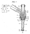
- valve plug 114 leaves from the valve seat 118, so the fuel supplied into the fuel injection valve is injected from a plurality of injection holes 119 provided to an orifice plate 116.
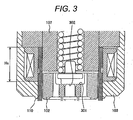
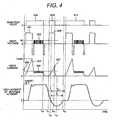
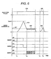
- the movable core 102 starts a valve closing sequence. Subsequently, before the displacement of the movable core 102 is reduced to 0 (zero) or less (namely, before the timing t 32 where the valve plug 114 sits on the valve seat 118, that is, before the timing when the engagement portion 301 of the movable core 102 is disengaged from the engagement portion 302 of the valve plug 114 to allow the movable core 102 to initiate its relative displacement in the valve closing direction with respect to the valve plug 114), an injection pulse 409 is turned on at t 31 , and thereby causing the high-voltage source to apply a high voltage 403 and supplying an intermediate current 407 to the electromagnetic coil 105.
Landscapes
- Engineering & Computer Science (AREA)
- Chemical & Material Sciences (AREA)
- Combustion & Propulsion (AREA)
- Mechanical Engineering (AREA)
- General Engineering & Computer Science (AREA)
- Fuel-Injection Apparatus (AREA)
- Electrical Control Of Air Or Fuel Supplied To Internal-Combustion Engine (AREA)
Claims (8)
- Dispositif de commande pour une valve d'injection de carburant ayant un électroaimant avec un noyau stationnaire (107) et une bobine électromagnétique (105), un noyau mobile (102) entraîné avec l'électroaimant, un bouchon de valve (114) assemblé dans le noyau mobile (102), un élément de pression (110) pour appliquer au noyau mobile (102) une pression dans une direction de fermeture de la valve, et le dispositif de commande (121) étant destiné à commander un voltage appliqué en accord avec une impulsion d'injection de carburant pour alimenter un courant à la bobine électromagnétique (105),
dans lequel le dispositif de commande (121) est configuré pour, entre la terminaison d'une application d'un voltage à la bobine électromagnétique, équivalente à la terminaison d'une première période d'injection de carburant, et l'amorçage d'une application d'un voltage à la bobine électromagnétique, équivalent à l'amorçage d'une seconde période d'injection de carburant ultérieure à la première période d'injection de carburant, appliquer un voltage à la bobine électromagnétique (105) à un niveau qui ne fait pas ouvrir la valve et alimenter un courant intermédiaire (407) pour la bobine électromagnétique (105) dans la même direction qu'une direction d'un courant de commande (404) pour ouvrir la valve, et
le dispositif de commande (120, 121) fixe l'application du voltage pour le courant intermédiaire (407) pour l'amorcer après avoir coupé l'application du voltage à la bobine électromagnétique dans la première période d'injection de carburant avant un premier instant quand le bouchon de valve (114) repose sur un siège de valve (118) et le terminer avant la moitié d'une période temporelle entre le premier instant (32) et un second instant quand une application d'un voltage de commande pour ouvrir la valve dans la seconde période d'injection de carburant est amorcée. - Dispositif de commande selon la revendication 1,
dans lequel le dispositif de commande (121) est en outre configuré pour établir une injection scindée consistant à scinder la masse du carburant par course d'injection individuelle en plusieurs fois qui sont la première période d'injection de carburant et la seconde période d'injection de carburant. - Dispositif de commande selon la revendication 1 ou 2, comprenant en outre un circuit amplificateur qui amplifie un voltage alimenté depuis une source de puissance vers un voltage plus élevé que celui de la source de puissance, et l'application du voltage pour le courant intermédiaire (407) est générée avec le circuit amplificateur de voltage.
- Dispositif de commande selon la revendication 1, 2 ou 3,
dans lequel le dispositif de commande (121) est en outre configuré pour terminer le voltage pour le courant intermédiaire avant qu'une intensité du courant intermédiaire (407) atteigne une intensité requise pour une force magnétique qui sépare le bouchon de valve (114) qui repose sur le siège valve (118), en éloignement du siège de valve (118). - Dispositif de commande selon l'une quelconque des revendications précédentes,
dans lequel le dispositif de commande (121) est en outre configuré pour établir un mode tel que chacune de la première période d'injection de carburant et de la seconde période d'injection de carburant inclut deux types de périodes d'application de voltage, dont une est une période d'application de voltage amplifié consistant à appliquer un voltage amplifié à la bobine électromagnétique (105) équivalent à un voltage de commande pour l'ouverture de la valve, et dont l'autre est une période d'application du voltage de la source de puissance consistant à appliquer à la bobine électromagnétique un voltage de la source de puissance afin de maintenir la valve ouverte au moyen d'une commutation ultérieurement à la période d'application du voltage amplifié,
dans lequel une valeur maximum du courant intermédiaire est fixée plus élevée qu'une valeur maximum d'un courant alimenté à la bobine électromagnétique (105) par le voltage de la source de puissance dans la période d'application du voltage de la source de puissance, et est fixée plus faible qu'une valeur maximum d'un courant alimenté à la bobine électromagnétique (105) par le voltage amplifié dans la période d'application du voltage amplifié. - Dispositif de commande selon l'une quelconque des revendications précédentes,
dans lequel le dispositif de commande (121) est en outre configuré pour générer une application d'un voltage pour alimenter le courant intermédiaire (407) en commandant une largeur d'impulsion d'une impulsion d'injection délivrée depuis une unité de commande moteur (120). - Dispositif de commande selon l'une quelconque des revendications 1 à 6,
dans lequel la valve d'injection de carburant à laquelle est appliqué le dispositif de commande (121) comprend le noyau mobile (102) ayant un mouvement relatif par rapport au bouchon de valve (114) pour absorber l'impact entre le bouchon de valve (114) et le siège de valve (118), et un élément de pression appliquant au noyau mobile une force dans une direction d'ouverture de la valve ; et
dans lequel la temporisation de la terminaison de l'application du voltage est obtenue en divisant le produit d'une vitesse d'impact entre le bouchon de valve (114) et le siège de valve (118) et d'une masse du noyau mobile (102) par la force de l'élément de pression (110). - Dispositif de commande pour une valve d'injection de carburant ayant un électroaimant avec un noyau stationnaire (102) et une bobine électromagnétique (105), un noyau mobile (102) entraîné avec l'électroaimant, un bouchon de valve (114) assemblé dans le noyau mobile (102), un élément de pression pour appliquer au noyau mobile (102) une pression dans une direction de fermeture de la valve, et le dispositif de commande (121) ayant pour fonction de commander un voltage appliqué en accord avec une impulsion d'injection de carburant pour alimenter un courant à la bobine électromagnétique (105),
dans lequel le dispositif de commande (121) est configuré pour, entre la terminaison d'un passage de courant dans la bobine électromagnétique équivalente à la terminaison d'une première période d'injection de carburant et l'amorçage d'un passage de courant dans la bobine électromagnétique équivalente à l'amorçage d'une seconde période d'injection de carburant ultérieure à la première période d'injection de carburant, alimenter la bobine électromagnétique (105) avec un courant intermédiaire dans la même direction qu'une direction d'un courant de commande pour ouvrir la valve, et
le dispositif de commande (121) fixe le courant intermédiaire pour l'amorcer après avoir coupé le passage de courant dans la bobine électromagnétique dans la première période d'injection de carburant avant un premier instant quand le bouchon de valve (114) repose sur un siège de valve (118), et le terminer avant la moitié d'une période temporelle entre le premier instant (32) et un second instant lorsqu'on amorce un passage de courant dans la bobine électromagnétique dans la seconde période d'injection de carburant.
Applications Claiming Priority (1)
| Application Number | Priority Date | Filing Date | Title |
|---|---|---|---|
| JP2011039180A JP5492806B2 (ja) | 2011-02-25 | 2011-02-25 | 電磁式燃料噴射弁の駆動装置 |
Publications (2)
| Publication Number | Publication Date |
|---|---|
| EP2492479A1 EP2492479A1 (fr) | 2012-08-29 |
| EP2492479B1 true EP2492479B1 (fr) | 2014-07-30 |
Family
ID=45656596
Family Applications (1)
| Application Number | Title | Priority Date | Filing Date |
|---|---|---|---|
| EP20120156796 Not-in-force EP2492479B1 (fr) | 2011-02-25 | 2012-02-24 | Dispositif de commande de soupape d'injection de carburant électromagnétique |
Country Status (4)
| Country | Link |
|---|---|
| US (1) | US8960157B2 (fr) |
| EP (1) | EP2492479B1 (fr) |
| JP (1) | JP5492806B2 (fr) |
| CN (1) | CN102650241B (fr) |
Families Citing this family (35)
| Publication number | Priority date | Publication date | Assignee | Title |
|---|---|---|---|---|
| DE102011075270A1 (de) * | 2011-05-04 | 2012-11-08 | Continental Automotive Gmbh | Verfahren und Vorrichtung zum Steuern eines Ventils |
| JP5572604B2 (ja) * | 2011-08-31 | 2014-08-13 | 日立オートモティブシステムズ株式会社 | 燃料噴射弁の制御装置 |
| DE102012207406A1 (de) * | 2012-05-04 | 2013-11-07 | Robert Bosch Gmbh | Ventil zum Zumessen von Fluid |
| DE102012211994B4 (de) * | 2012-07-10 | 2024-08-08 | Vitesco Technologies GmbH | Steuergerät zur Ansteuerung zumindest einen Kraftstoffeinspritzventils und Schaltungsanordnung mit einem solchen Steuergerät |
| JP5874607B2 (ja) | 2012-11-05 | 2016-03-02 | 株式会社デンソー | 燃料噴射制御装置および燃料噴射システム |
| JP5772788B2 (ja) * | 2012-11-05 | 2015-09-02 | 株式会社デンソー | 燃料噴射制御装置および燃料噴射システム |
| JP5880872B2 (ja) * | 2013-01-14 | 2016-03-09 | 株式会社デンソー | 燃料噴射弁及び燃料噴射装置 |
| JP5849975B2 (ja) * | 2013-02-25 | 2016-02-03 | 株式会社デンソー | 燃料噴射制御装置および燃料噴射システム |
| DE102013203130A1 (de) * | 2013-02-26 | 2014-08-28 | Robert Bosch Gmbh | Verfahren zur Steuerung eines Einspritzvorgangs eines Magnetinjektors |
| DE112014002349B4 (de) | 2013-05-10 | 2019-12-05 | Denso Corporation | Kraftstoffeinspritzsteuervorrichtung und Kraftstoffeinspritzsystem |
| EP3597899B1 (fr) * | 2013-07-29 | 2026-01-21 | Astemo, Ltd. | Dispositif d'entraînement pour dispositif d'injection de carburant et système d'injection de carburant |
| US9347395B2 (en) * | 2013-08-22 | 2016-05-24 | GM Global Technology Operations LLC | Method for improving closely-spaced multiple-injection performance from solenoid actuated fuel injectors |
| US9441594B2 (en) * | 2013-08-27 | 2016-09-13 | Caterpillar Inc. | Valve actuator assembly with current trim and fuel injector using same |
| JP6318575B2 (ja) * | 2013-11-21 | 2018-05-09 | 株式会社デンソー | 燃料噴射制御装置および燃料噴射システム |
| JP6233080B2 (ja) | 2014-02-10 | 2017-11-22 | 株式会社デンソー | 燃料噴射制御装置 |
| JP6413582B2 (ja) * | 2014-10-03 | 2018-10-31 | 株式会社デンソー | 内燃機関の制御装置 |
| DE102015217955A1 (de) * | 2014-10-21 | 2016-04-21 | Robert Bosch Gmbh | Vorrichtung zur Steuerung von wenigstens einem schaltbaren Ventil |
| JP6511266B2 (ja) * | 2014-12-25 | 2019-05-15 | 日立オートモティブシステムズ株式会社 | 燃料噴射弁制御装置 |
| JP6286714B2 (ja) * | 2015-05-15 | 2018-03-07 | 株式会社ケーヒン | 燃料噴射制御装置 |
| JP6263811B2 (ja) * | 2015-05-15 | 2018-01-24 | 株式会社ケーヒン | 燃料噴射制御装置 |
| DE102015209783A1 (de) * | 2015-05-28 | 2016-12-01 | Robert Bosch Gmbh | Verfahren zur Ansteuerung eines Kraftstoffinjektors |
| JP6477301B2 (ja) * | 2015-06-29 | 2019-03-06 | 株式会社デンソー | 噴射制御装置 |
| JP6107913B2 (ja) * | 2015-10-07 | 2017-04-05 | 株式会社デンソー | 燃料噴射制御装置および燃料噴射システム |
| JP6557608B2 (ja) * | 2016-01-22 | 2019-08-07 | 日立オートモティブシステムズ株式会社 | 燃料噴射装置の制御装置 |
| US10210977B2 (en) * | 2016-06-03 | 2019-02-19 | Lam Research Corporation | Valve operation booster |
| JP6294422B2 (ja) * | 2016-09-08 | 2018-03-14 | 日立オートモティブシステムズ株式会社 | 燃料噴射装置の駆動装置および燃料噴射システム |
| DE102016219890B3 (de) * | 2016-10-12 | 2017-08-03 | Continental Automotive Gmbh | Verfahren und Steuereinrichtung zum Steuern eines Schaltventils |
| FR3061746B1 (fr) * | 2017-01-10 | 2020-09-25 | Continental Automotive France | Procede de correction d'une duree d'injection de carburant dans un cylindre de moteur thermique de vehicule automobile |
| JP6856387B2 (ja) * | 2017-01-20 | 2021-04-07 | 日立Astemo株式会社 | 燃料噴射装置の駆動装置 |
| JP6720935B2 (ja) * | 2017-07-28 | 2020-07-08 | 株式会社Soken | 燃料噴射制御装置及び燃料噴射制御方法 |
| JP6844501B2 (ja) * | 2017-10-31 | 2021-03-17 | 株式会社デンソー | 燃料噴射弁の制御装置、及び燃料噴射弁の制御方法 |
| CN108656741B (zh) * | 2018-05-21 | 2020-06-02 | 苏州华兴源创科技股份有限公司 | 一种利用电磁阀控制的喷墨打点装置和方法 |
| US11480129B2 (en) * | 2021-02-19 | 2022-10-25 | Caterpillar Inc. | Fuel system and fuel injector control strategy for stabilized injection control valve closing |
| JP2025185940A (ja) * | 2024-06-11 | 2025-12-23 | Astemo株式会社 | 燃料噴射制御装置及び燃料噴射制御方法 |
| CN119393246B (zh) * | 2024-10-30 | 2025-10-24 | 潍柴动力股份有限公司 | 一种甲醇喷射器控制方法及相关装置 |
Family Cites Families (20)
| Publication number | Priority date | Publication date | Assignee | Title |
|---|---|---|---|---|
| FR2345595A1 (fr) * | 1976-03-26 | 1977-10-21 | Bosch Gmbh Robert | Installation pour la commande, avec un courant regle, d'organes de manoeuvre electromagnetiques |
| US5445128A (en) * | 1993-08-27 | 1995-08-29 | Detroit Diesel Corporation | Method for engine control |
| JP3134724B2 (ja) * | 1995-02-15 | 2001-02-13 | トヨタ自動車株式会社 | 内燃機関の弁駆動装置 |
| JP3613885B2 (ja) * | 1996-05-24 | 2005-01-26 | 国産電機株式会社 | 内燃機関用インジェクタの駆動制御方法及び駆動制御装置 |
| US5865371A (en) | 1996-07-26 | 1999-02-02 | Siemens Automotive Corporation | Armature motion control method and apparatus for a fuel injector |
| JP3534167B2 (ja) * | 1998-05-25 | 2004-06-07 | 国産電機株式会社 | インジェクタ駆動方法及び駆動回路 |
| JP3527857B2 (ja) * | 1998-12-25 | 2004-05-17 | 株式会社日立製作所 | 燃料噴射装置及び内燃機関 |
| US6705277B1 (en) * | 2000-07-13 | 2004-03-16 | Caterpillar Inc | Method and apparatus for delivering multiple fuel injections to the cylinder of an engine wherein the pilot fuel injection occurs during the intake stroke |
| US6467452B1 (en) * | 2000-07-13 | 2002-10-22 | Caterpillar Inc | Method and apparatus for delivering multiple fuel injections to the cylinder of an internal combustion engine |
| JP2002115591A (ja) * | 2000-10-04 | 2002-04-19 | Nissan Motor Co Ltd | 内燃機関の燃料噴射装置 |
| JP2002364768A (ja) * | 2001-06-07 | 2002-12-18 | Denso Corp | 電磁弁駆動装置 |
| JP2003120848A (ja) * | 2001-10-18 | 2003-04-23 | Bosch Automotive Systems Corp | 電磁弁駆動制御方法及び電磁弁駆動制御装置 |
| US6766788B2 (en) * | 2002-01-31 | 2004-07-27 | Visteon Global Technologies, Inc. | Pre-charging strategy for fuel injector fast opening |
| DE60313667T2 (de) * | 2002-12-10 | 2007-12-27 | Mikuni Corp. | Steuerverfahren und vorrichtung zur kraftstoffeinspritzung |
| JP3810372B2 (ja) * | 2003-01-28 | 2006-08-16 | 三菱電機株式会社 | 燃料噴射弁の制御装置 |
| US6935580B2 (en) * | 2003-02-10 | 2005-08-30 | Caterpillar Inc | Valve assembly having multiple rate shaping capabilities and fuel injector using same |
| JP4148127B2 (ja) * | 2003-12-12 | 2008-09-10 | 株式会社デンソー | 燃料噴射装置 |
| JP2008095521A (ja) | 2006-10-06 | 2008-04-24 | Denso Corp | 電磁弁装置およびそれを用いた燃料噴射システム |
| JP4474423B2 (ja) | 2007-01-12 | 2010-06-02 | 日立オートモティブシステムズ株式会社 | 内燃機関制御装置 |
| JP4691523B2 (ja) | 2007-05-09 | 2011-06-01 | 日立オートモティブシステムズ株式会社 | 電磁式燃料噴射弁の制御回路 |
-
2011
- 2011-02-25 JP JP2011039180A patent/JP5492806B2/ja active Active
-
2012
- 2012-02-10 CN CN201210030585.2A patent/CN102650241B/zh not_active Expired - Fee Related
- 2012-02-23 US US13/403,506 patent/US8960157B2/en active Active
- 2012-02-24 EP EP20120156796 patent/EP2492479B1/fr not_active Not-in-force
Also Published As
| Publication number | Publication date |
|---|---|
| US8960157B2 (en) | 2015-02-24 |
| CN102650241A (zh) | 2012-08-29 |
| JP2012177303A (ja) | 2012-09-13 |
| CN102650241B (zh) | 2015-01-07 |
| US20120216783A1 (en) | 2012-08-30 |
| JP5492806B2 (ja) | 2014-05-14 |
| EP2492479A1 (fr) | 2012-08-29 |
Similar Documents
| Publication | Publication Date | Title |
|---|---|---|
| EP2492479B1 (fr) | Dispositif de commande de soupape d'injection de carburant électromagnétique | |
| US10900435B2 (en) | Drive unit of fuel injection device | |
| US9714626B2 (en) | Drive device for fuel injection device | |
| US10082117B2 (en) | Fuel injection device | |
| JP4691523B2 (ja) | 電磁式燃料噴射弁の制御回路 | |
| CN102639860B (zh) | 电磁式燃料喷射阀的驱动电路 | |
| JP6708741B2 (ja) | 燃料噴射装置の制御装置 | |
| WO2013031422A1 (fr) | Appareil de commande pour soupape d'injection de carburant | |
| US10662886B2 (en) | Control device for fuel injection device | |
| WO2018135219A1 (fr) | Dispositif d'entraînement pour dispositif d'injection de carburant | |
| Lu et al. | Impact of control methods on dynamic characteristic of high speed solenoid injectors | |
| CN1952381B (zh) | 带容量控制机构的高压燃料供给泵的控制器 | |
| JP7177458B2 (ja) | 燃料噴射装置を制御する制御装置 | |
| JP5865409B2 (ja) | 電磁式燃料噴射弁の駆動装置 | |
| JP6561184B2 (ja) | 燃料噴射装置の駆動装置 | |
| JP2015206371A (ja) | 電磁弁装置の駆動装置 | |
| WO2020100485A1 (fr) | Dispositif de commande pour appareil d'injection de carburant | |
| JP2018080582A (ja) | 燃料噴射装置の制御装置 | |
| JP5799130B2 (ja) | 電磁弁装置の駆動装置及び電磁弁装置 |
Legal Events
| Date | Code | Title | Description |
|---|---|---|---|
| PUAI | Public reference made under article 153(3) epc to a published international application that has entered the european phase |
Free format text: ORIGINAL CODE: 0009012 |
|
| 17P | Request for examination filed |
Effective date: 20120323 |
|
| AK | Designated contracting states |
Kind code of ref document: A1 Designated state(s): AL AT BE BG CH CY CZ DE DK EE ES FI FR GB GR HR HU IE IS IT LI LT LU LV MC MK MT NL NO PL PT RO RS SE SI SK SM TR |
|
| AX | Request for extension of the european patent |
Extension state: BA ME |
|
| GRAP | Despatch of communication of intention to grant a patent |
Free format text: ORIGINAL CODE: EPIDOSNIGR1 |
|
| RIC1 | Information provided on ipc code assigned before grant |
Ipc: F02D 41/20 20060101AFI20140113BHEP Ipc: F02D 41/40 20060101ALN20140113BHEP |
|
| INTG | Intention to grant announced |
Effective date: 20140212 |
|
| RIN1 | Information on inventor provided before grant (corrected) |
Inventor name: KUSAKABE, RYO Inventor name: ABE, MOTOYUKI Inventor name: MAYUZUMI, TAKUYA Inventor name: MAEKAWA, NORIYUKI Inventor name: ISHIKAWA, TOHRU Inventor name: EHARA, HIDEHARU |
|
| GRAS | Grant fee paid |
Free format text: ORIGINAL CODE: EPIDOSNIGR3 |
|
| GRAA | (expected) grant |
Free format text: ORIGINAL CODE: 0009210 |
|
| AK | Designated contracting states |
Kind code of ref document: B1 Designated state(s): AL AT BE BG CH CY CZ DE DK EE ES FI FR GB GR HR HU IE IS IT LI LT LU LV MC MK MT NL NO PL PT RO RS SE SI SK SM TR |
|
| REG | Reference to a national code |
Ref country code: GB Ref legal event code: FG4D |
|
| REG | Reference to a national code |
Ref country code: CH Ref legal event code: EP |
|
| REG | Reference to a national code |
Ref country code: AT Ref legal event code: REF Ref document number: 680120 Country of ref document: AT Kind code of ref document: T Effective date: 20140815 |
|
| REG | Reference to a national code |
Ref country code: IE Ref legal event code: FG4D |
|
| REG | Reference to a national code |
Ref country code: DE Ref legal event code: R096 Ref document number: 602012002546 Country of ref document: DE Effective date: 20140911 |
|
| REG | Reference to a national code |
Ref country code: AT Ref legal event code: MK05 Ref document number: 680120 Country of ref document: AT Kind code of ref document: T Effective date: 20140730 |
|
| REG | Reference to a national code |
Ref country code: NL Ref legal event code: VDEP Effective date: 20140730 |
|
| REG | Reference to a national code |
Ref country code: LT Ref legal event code: MG4D |
|
| PG25 | Lapsed in a contracting state [announced via postgrant information from national office to epo] |
Ref country code: LT Free format text: LAPSE BECAUSE OF FAILURE TO SUBMIT A TRANSLATION OF THE DESCRIPTION OR TO PAY THE FEE WITHIN THE PRESCRIBED TIME-LIMIT Effective date: 20140730 Ref country code: ES Free format text: LAPSE BECAUSE OF FAILURE TO SUBMIT A TRANSLATION OF THE DESCRIPTION OR TO PAY THE FEE WITHIN THE PRESCRIBED TIME-LIMIT Effective date: 20140730 Ref country code: BG Free format text: LAPSE BECAUSE OF FAILURE TO SUBMIT A TRANSLATION OF THE DESCRIPTION OR TO PAY THE FEE WITHIN THE PRESCRIBED TIME-LIMIT Effective date: 20141030 Ref country code: SE Free format text: LAPSE BECAUSE OF FAILURE TO SUBMIT A TRANSLATION OF THE DESCRIPTION OR TO PAY THE FEE WITHIN THE PRESCRIBED TIME-LIMIT Effective date: 20140730 Ref country code: GR Free format text: LAPSE BECAUSE OF FAILURE TO SUBMIT A TRANSLATION OF THE DESCRIPTION OR TO PAY THE FEE WITHIN THE PRESCRIBED TIME-LIMIT Effective date: 20141031 Ref country code: PT Free format text: LAPSE BECAUSE OF FAILURE TO SUBMIT A TRANSLATION OF THE DESCRIPTION OR TO PAY THE FEE WITHIN THE PRESCRIBED TIME-LIMIT Effective date: 20141202 Ref country code: FI Free format text: LAPSE BECAUSE OF FAILURE TO SUBMIT A TRANSLATION OF THE DESCRIPTION OR TO PAY THE FEE WITHIN THE PRESCRIBED TIME-LIMIT Effective date: 20140730 Ref country code: NO Free format text: LAPSE BECAUSE OF FAILURE TO SUBMIT A TRANSLATION OF THE DESCRIPTION OR TO PAY THE FEE WITHIN THE PRESCRIBED TIME-LIMIT Effective date: 20141030 |
|
| PG25 | Lapsed in a contracting state [announced via postgrant information from national office to epo] |
Ref country code: IS Free format text: LAPSE BECAUSE OF FAILURE TO SUBMIT A TRANSLATION OF THE DESCRIPTION OR TO PAY THE FEE WITHIN THE PRESCRIBED TIME-LIMIT Effective date: 20141130 Ref country code: LV Free format text: LAPSE BECAUSE OF FAILURE TO SUBMIT A TRANSLATION OF THE DESCRIPTION OR TO PAY THE FEE WITHIN THE PRESCRIBED TIME-LIMIT Effective date: 20140730 Ref country code: HR Free format text: LAPSE BECAUSE OF FAILURE TO SUBMIT A TRANSLATION OF THE DESCRIPTION OR TO PAY THE FEE WITHIN THE PRESCRIBED TIME-LIMIT Effective date: 20140730 Ref country code: RS Free format text: LAPSE BECAUSE OF FAILURE TO SUBMIT A TRANSLATION OF THE DESCRIPTION OR TO PAY THE FEE WITHIN THE PRESCRIBED TIME-LIMIT Effective date: 20140730 Ref country code: CY Free format text: LAPSE BECAUSE OF FAILURE TO SUBMIT A TRANSLATION OF THE DESCRIPTION OR TO PAY THE FEE WITHIN THE PRESCRIBED TIME-LIMIT Effective date: 20140730 Ref country code: NL Free format text: LAPSE BECAUSE OF FAILURE TO SUBMIT A TRANSLATION OF THE DESCRIPTION OR TO PAY THE FEE WITHIN THE PRESCRIBED TIME-LIMIT Effective date: 20140730 Ref country code: PL Free format text: LAPSE BECAUSE OF FAILURE TO SUBMIT A TRANSLATION OF THE DESCRIPTION OR TO PAY THE FEE WITHIN THE PRESCRIBED TIME-LIMIT Effective date: 20140730 Ref country code: AT Free format text: LAPSE BECAUSE OF FAILURE TO SUBMIT A TRANSLATION OF THE DESCRIPTION OR TO PAY THE FEE WITHIN THE PRESCRIBED TIME-LIMIT Effective date: 20140730 |
|
| PG25 | Lapsed in a contracting state [announced via postgrant information from national office to epo] |
Ref country code: SK Free format text: LAPSE BECAUSE OF FAILURE TO SUBMIT A TRANSLATION OF THE DESCRIPTION OR TO PAY THE FEE WITHIN THE PRESCRIBED TIME-LIMIT Effective date: 20140730 Ref country code: EE Free format text: LAPSE BECAUSE OF FAILURE TO SUBMIT A TRANSLATION OF THE DESCRIPTION OR TO PAY THE FEE WITHIN THE PRESCRIBED TIME-LIMIT Effective date: 20140730 Ref country code: IT Free format text: LAPSE BECAUSE OF FAILURE TO SUBMIT A TRANSLATION OF THE DESCRIPTION OR TO PAY THE FEE WITHIN THE PRESCRIBED TIME-LIMIT Effective date: 20140730 Ref country code: DK Free format text: LAPSE BECAUSE OF FAILURE TO SUBMIT A TRANSLATION OF THE DESCRIPTION OR TO PAY THE FEE WITHIN THE PRESCRIBED TIME-LIMIT Effective date: 20140730 Ref country code: RO Free format text: LAPSE BECAUSE OF FAILURE TO SUBMIT A TRANSLATION OF THE DESCRIPTION OR TO PAY THE FEE WITHIN THE PRESCRIBED TIME-LIMIT Effective date: 20140730 Ref country code: CZ Free format text: LAPSE BECAUSE OF FAILURE TO SUBMIT A TRANSLATION OF THE DESCRIPTION OR TO PAY THE FEE WITHIN THE PRESCRIBED TIME-LIMIT Effective date: 20140730 |
|
| REG | Reference to a national code |
Ref country code: DE Ref legal event code: R097 Ref document number: 602012002546 Country of ref document: DE |
|
| PLBE | No opposition filed within time limit |
Free format text: ORIGINAL CODE: 0009261 |
|
| STAA | Information on the status of an ep patent application or granted ep patent |
Free format text: STATUS: NO OPPOSITION FILED WITHIN TIME LIMIT |
|
| PG25 | Lapsed in a contracting state [announced via postgrant information from national office to epo] |
Ref country code: BE Free format text: LAPSE BECAUSE OF NON-PAYMENT OF DUE FEES Effective date: 20150228 |
|
| 26N | No opposition filed |
Effective date: 20150504 |
|
| PG25 | Lapsed in a contracting state [announced via postgrant information from national office to epo] |
Ref country code: LU Free format text: LAPSE BECAUSE OF FAILURE TO SUBMIT A TRANSLATION OF THE DESCRIPTION OR TO PAY THE FEE WITHIN THE PRESCRIBED TIME-LIMIT Effective date: 20150224 |
|
| REG | Reference to a national code |
Ref country code: CH Ref legal event code: PL |
|
| PG25 | Lapsed in a contracting state [announced via postgrant information from national office to epo] |
Ref country code: CH Free format text: LAPSE BECAUSE OF NON-PAYMENT OF DUE FEES Effective date: 20150228 Ref country code: LI Free format text: LAPSE BECAUSE OF NON-PAYMENT OF DUE FEES Effective date: 20150228 Ref country code: MC Free format text: LAPSE BECAUSE OF FAILURE TO SUBMIT A TRANSLATION OF THE DESCRIPTION OR TO PAY THE FEE WITHIN THE PRESCRIBED TIME-LIMIT Effective date: 20140730 |
|
| REG | Reference to a national code |
Ref country code: IE Ref legal event code: MM4A |
|
| PG25 | Lapsed in a contracting state [announced via postgrant information from national office to epo] |
Ref country code: SI Free format text: LAPSE BECAUSE OF FAILURE TO SUBMIT A TRANSLATION OF THE DESCRIPTION OR TO PAY THE FEE WITHIN THE PRESCRIBED TIME-LIMIT Effective date: 20140730 |
|
| REG | Reference to a national code |
Ref country code: FR Ref legal event code: PLFP Year of fee payment: 5 |
|
| PG25 | Lapsed in a contracting state [announced via postgrant information from national office to epo] |
Ref country code: IE Free format text: LAPSE BECAUSE OF NON-PAYMENT OF DUE FEES Effective date: 20150224 |
|
| PGFP | Annual fee paid to national office [announced via postgrant information from national office to epo] |
Ref country code: FR Payment date: 20160108 Year of fee payment: 5 Ref country code: GB Payment date: 20160224 Year of fee payment: 5 |
|
| PG25 | Lapsed in a contracting state [announced via postgrant information from national office to epo] |
Ref country code: BE Free format text: LAPSE BECAUSE OF FAILURE TO SUBMIT A TRANSLATION OF THE DESCRIPTION OR TO PAY THE FEE WITHIN THE PRESCRIBED TIME-LIMIT Effective date: 20140730 |
|
| PG25 | Lapsed in a contracting state [announced via postgrant information from national office to epo] |
Ref country code: MT Free format text: LAPSE BECAUSE OF FAILURE TO SUBMIT A TRANSLATION OF THE DESCRIPTION OR TO PAY THE FEE WITHIN THE PRESCRIBED TIME-LIMIT Effective date: 20140730 |
|
| PG25 | Lapsed in a contracting state [announced via postgrant information from national office to epo] |
Ref country code: HU Free format text: LAPSE BECAUSE OF FAILURE TO SUBMIT A TRANSLATION OF THE DESCRIPTION OR TO PAY THE FEE WITHIN THE PRESCRIBED TIME-LIMIT; INVALID AB INITIO Effective date: 20120224 Ref country code: SM Free format text: LAPSE BECAUSE OF FAILURE TO SUBMIT A TRANSLATION OF THE DESCRIPTION OR TO PAY THE FEE WITHIN THE PRESCRIBED TIME-LIMIT Effective date: 20140730 |
|
| PG25 | Lapsed in a contracting state [announced via postgrant information from national office to epo] |
Ref country code: TR Free format text: LAPSE BECAUSE OF FAILURE TO SUBMIT A TRANSLATION OF THE DESCRIPTION OR TO PAY THE FEE WITHIN THE PRESCRIBED TIME-LIMIT Effective date: 20140730 |
|
| GBPC | Gb: european patent ceased through non-payment of renewal fee |
Effective date: 20170224 |
|
| REG | Reference to a national code |
Ref country code: FR Ref legal event code: ST Effective date: 20171031 |
|
| PG25 | Lapsed in a contracting state [announced via postgrant information from national office to epo] |
Ref country code: FR Free format text: LAPSE BECAUSE OF NON-PAYMENT OF DUE FEES Effective date: 20170228 |
|
| PG25 | Lapsed in a contracting state [announced via postgrant information from national office to epo] |
Ref country code: GB Free format text: LAPSE BECAUSE OF NON-PAYMENT OF DUE FEES Effective date: 20170224 |
|
| PG25 | Lapsed in a contracting state [announced via postgrant information from national office to epo] |
Ref country code: MK Free format text: LAPSE BECAUSE OF FAILURE TO SUBMIT A TRANSLATION OF THE DESCRIPTION OR TO PAY THE FEE WITHIN THE PRESCRIBED TIME-LIMIT Effective date: 20140730 |
|
| PG25 | Lapsed in a contracting state [announced via postgrant information from national office to epo] |
Ref country code: AL Free format text: LAPSE BECAUSE OF FAILURE TO SUBMIT A TRANSLATION OF THE DESCRIPTION OR TO PAY THE FEE WITHIN THE PRESCRIBED TIME-LIMIT Effective date: 20140730 |
|
| REG | Reference to a national code |
Ref country code: DE Ref legal event code: R082 Ref document number: 602012002546 Country of ref document: DE Representative=s name: MERH-IP MATIAS ERNY REICHL HOFFMANN PATENTANWA, DE Ref country code: DE Ref legal event code: R081 Ref document number: 602012002546 Country of ref document: DE Owner name: HITACHI ASTEMO, LTD., HITACHINAKA-SHI, JP Free format text: FORMER OWNER: HITACHI AUTOMOTIVE SYSTEMS, LTD., HITACHINAKA-SHI, IBARAKI, JP |
|
| PGFP | Annual fee paid to national office [announced via postgrant information from national office to epo] |
Ref country code: DE Payment date: 20221229 Year of fee payment: 12 |
|
| REG | Reference to a national code |
Ref country code: DE Ref legal event code: R119 Ref document number: 602012002546 Country of ref document: DE |
|
| PG25 | Lapsed in a contracting state [announced via postgrant information from national office to epo] |
Ref country code: DE Free format text: LAPSE BECAUSE OF NON-PAYMENT OF DUE FEES Effective date: 20240903 |
|
| PG25 | Lapsed in a contracting state [announced via postgrant information from national office to epo] |
Ref country code: DE Free format text: LAPSE BECAUSE OF NON-PAYMENT OF DUE FEES Effective date: 20240903 |