EP2492479A1 - Dispositif de commande de soupape d'injection de carburant électromagnétique - Google Patents
Dispositif de commande de soupape d'injection de carburant électromagnétique Download PDFInfo
- Publication number
- EP2492479A1 EP2492479A1 EP12156796A EP12156796A EP2492479A1 EP 2492479 A1 EP2492479 A1 EP 2492479A1 EP 12156796 A EP12156796 A EP 12156796A EP 12156796 A EP12156796 A EP 12156796A EP 2492479 A1 EP2492479 A1 EP 2492479A1
- Authority
- EP
- European Patent Office
- Prior art keywords
- valve
- fuel injection
- voltage
- current
- electromagnetic coil
- Prior art date
- Legal status (The legal status is an assumption and is not a legal conclusion. Google has not performed a legal analysis and makes no representation as to the accuracy of the status listed.)
- Granted
Links
Images


Classifications
-
- F—MECHANICAL ENGINEERING; LIGHTING; HEATING; WEAPONS; BLASTING
- F02—COMBUSTION ENGINES; HOT-GAS OR COMBUSTION-PRODUCT ENGINE PLANTS
- F02D—CONTROLLING COMBUSTION ENGINES
- F02D41/00—Electrical control of supply of combustible mixture or its constituents
- F02D41/20—Output circuits, e.g. for controlling currents in command coils
- F02D2041/202—Output circuits, e.g. for controlling currents in command coils characterised by the control of the circuit
- F02D2041/2037—Output circuits, e.g. for controlling currents in command coils characterised by the control of the circuit for preventing bouncing of the valve needle
-
- F—MECHANICAL ENGINEERING; LIGHTING; HEATING; WEAPONS; BLASTING
- F02—COMBUSTION ENGINES; HOT-GAS OR COMBUSTION-PRODUCT ENGINE PLANTS
- F02D—CONTROLLING COMBUSTION ENGINES
- F02D41/00—Electrical control of supply of combustible mixture or its constituents
- F02D41/30—Controlling fuel injection
- F02D41/38—Controlling fuel injection of the high pressure type
- F02D41/40—Controlling fuel injection of the high pressure type with means for controlling injection timing or duration
- F02D41/402—Multiple injections
Definitions
- the present invention relates to a drive device for an electromagnetic fuel injection valve used, for instance, for an internal combustion engine.
- a normally-closed electromagnetic fuel injection valve is provided with a pressure member such as a spring whose force is applied to a movable core including a valve plug in a valve closing direction.
- An actuator of the electromagnetic fuel injection valve includes an electromagnetic coil, a stationary core, and the movable core, and upon a current being supplied to the electromagnetic coil, an attractive force is generated between the stationary core and the movable core.
- the valve plug leaves from a valve seat to make a valve opening.
- the attractive force between the stationary core and the movable core is set free. Thereby, the injection valve is closed by force of the pressure.
- JP 2002-115591A discloses a method of controlling the valve closing speed of the movable core by supplying the current to the electromagnetic coil again just after once having shut off the current for the electromagnetic coil. This method can reduce an impact force of the valve plug against the valve seat at the time when the valve plug sits on the valve seat to close the valve, and thereby reduce bound of the valve plug due to impact on the valve seat.
- JP2008-280876A discloses a method of, when a valve operation is done from a valve open state to a valve closed state, retuning the valve plug quickly to its initial position of the beginning of a valve opening operation, by energizing the electromagnetic coil just after the valve plug sat on the valve seat with a bound on impact. That is, thereby, the valve plug is applied with a force through the movable core in a direction opposite to the valve closing direction, so a rebound motion of the valve plug is suppressed just after the valve plug sat on the valve seat. This enables the valve plug to quickly return to its initial position of the beginning of the valve opening operation.
- a downsizing-engine is proposed.
- the downsizing-engine is configured to reduce exhaust emissions for downsizing purposes while acquiring an adequate output with a supercharger.
- the downsizing-engine it can since reduce exhaust emissions, it also can reduce fuel pumping loss andpumpingmechanical friction resulting in reduction of fuel consumption. Meanwhile, the use of the supercharger makes it possible to acquire an adequate output.
- a direct injection method is used to produce an intake air cooling effect. This makes it possible to suppress a compression ratio decrease caused by supercharging and achieve low fuel cost.
- split injection is proposed as a method of preventing the injected fuel from reaching the cylinder wall surface by splitting fuel mass per a one-time injection stroke into several injections.
- JP 2002-115591A discloses a driving method of the movable core only before the valve plug sits on the valve seat, but does not give special consideration to behaviors of the valve plug and its movable core after the valve plug sat on the valve seat with impact. After the valve plug sat on the valve seat, the valve plug and its movable core continue with their rebound motion on impact on the valve seat.
- the movable core continuously has the relative motion with respect to the valve plug after the valve plug sat on the valve seat with impact. Therefore, it takes some time for the movable core to come to rest, so it is necessary to allow a sufficient time interval between one injection and the next. Further, after the valve plug sat on the valve seat with impact, the movable core has the following behavior. That is, first of all, the movable core has a motion independent of the valve plug for a brief moment because of having a relative motion with respect to the valve plug to absorb the impact between the valve plug and the valve seat.
- the movable core engages the valve plug again by working of a spring in a valve opening direction.
- the movable core pushes up the valve plug, and thereby the valve plug may leave from the valve seat in spite of the valve closing operation.
- JP 2008-280876A discloses of reducing the rest time of the valve plug by supplying an intermediate current just after the valve plug sat on the valve seat.
- the present invention has been made in view of the above circumstances, and its object is to provide a drive device for a fuel injection valve capable of reducing a time interval between a first fuel injection period and a second fuel injection period subsequent to the first fuel injection period.
- the drive device for an fuel injection valve of the present invention is configured to, during a time interval between an earlier fuel injection (first fuel injection) and a later fuel injection (second fuel injection), supply an electromagnetic coil with an intermediate current at a voltage with a level of not opening the valve. Further, the drive device sets a voltage application for supplying the intermediate current to initiate before a valve closing in the earlier fuel injection and terminate before half a period of time between a first instant when the valve is closed in the earlier fuel injection and a second instant when a supply of a drive current for opening the valve is initiated in the later fuel injection.
- the present invention it is possible to shorten an interval between the first fuel injection period and the second fuel injection period subsequent to the first fuel injection period.
- a fuel injection valve can be driven while the split injection is performed at reduced intervals.
- FIGS. 1 to 3 A configuration and an operation of a fuel injection device according to an embodiment of the present invention will now be described with reference to FIGS. 1 to 3 .
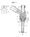
- FIG. 1 represents a configuration of the fuel injection device including afuelinjection valve with a vertical cross-sectional view, an EDU (drive circuit unit) 121 and an ECU (engine control unit) 120 for driving and controlling the fuel injection valve.
- the ECU 120 and the EDU 121 may be integrated into a single part.
- a drive device for the fuel injection valve is at least a device for generating a drive voltage for the fuel injection valve, and may be an integrated combination of the ECU and EDU or formed by the EDU alone.
- the ECU 120 receives signals indicative of an engine status from various sensors and determines an appropriate injection pulse width and injection timing in accordance with operating conditions for an internal combustion engine.
- An injection pulse output from the ECU 120 is received with the EDU 121 of the fuel injection valve through a signal line 123.
- the EDU 121 controls a voltage to be applied to an electromagnetic coil 105, and supplies a current.
- the ECU 120 communicates with the EDU 121 through a communication line 122 and can change over a drive current which is generated by the EDU 121, in accordance with the operating conditions and the pressure of fuel to be supplied to the fuel injection valve.
- the EDU 121 can change a control constant by communicating with the ECU 120, so a current waveform to be supplied to the electromagnetic coil can be changed with the control constant.
- a split injection control is executed either by allowing the ECU 120 to output a voltage application command pulse for supplying an intermediate current for split injection or by having the ECU 120 transmit the control constant to the EDU 121 to let the EDU 121 directly supply the intermediate current.
- FIG. 1 represents the vertical cross-sectional view of the fuel injection valve illustrated in FIG. 1 , and referring to a relationship between an injection pulse and displacements of a valve plug 114 and a movable core 102 illustrated in FIG. 2.
- FIG. 2 represents the relationship between the injection pulse output from the ECU, a behavior of the valve plug 114, and a behavior of the movable core 102.
- the fuel injection device shown in FIG. 1 is a normally-closed electromagnetic fuel injection valve.
- the valve plug 114 Upon the electromagnetic coil 105 being non-energized, the valve plug 114 is pressed in a valve closing direction by a spring (first spring) 110 so as to sit on a valve seat 118 resulting in a valve closing.
- first spring which may be referred to as an anchor or a movable element
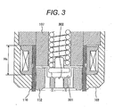
- second spring zero spring 112 such that an engagement portion 301 of the movable core 102 is in contact with an engagement portion 302 (refer to FIG. 3 ) of the valve plug 114 having an engagement to each other.
- the fuel injection valve has a magnetic circuit being constituted by the magnetic core 107, the movable core 102, and a yoke 103.
- an excitation current flows through the electromagnetic coil 105, thereby a magnetic flux is generated in the magnetic circuit.
- a magnetic attractive force is then generated between the magnetic core 107 and the movable core 102.
- the movable core 102 moves upward (toward the magnetic core 107).
- the engagement portion 301 of the movable core 102 comes into contact (engages) with the engagement portion 302 of the valve plug 114, so a force transmission occurs between the engagement portion 301 and the engagement portion 302.
- the movable core 102 and the valve plug 114 engages with each other and move together upward (toward the magnetic core 107).
- An upper end face of the movable core 102 then impacts on the lower surface of the magnetic core 107 resulting in the valve opening.
- valve plug 114 leaves from the valve seat 118, so the fuel supplied into the fuel injection valve is injected from a plurality of injection holes 119 provided to an orifice plate 116.
- the valve plug 114 sits on the valve seat 118 (comes into contact with the valve seat 118) thereby to close the injection holes 119. At this time, the force applied to the valve plug 114 by the spring 110 is transmitted to the movable core 102 through the engagement portion 302 of the valve plug 114 and the engagement portion 301 of the movable core 102.
- the movable core 102 moves downward (in the valve closing direction) continuously independent from the valve plug 14 while compressing a zero spring 112 for engagement between engagement portions 301 and 302 (the zero spring 112 although works in the valve opening direction, its force is smaller than that of the spring 110 working in the valve closing direction).
- the engagement portion 301 of the movable core 102 leaves from the engagement portion 302 of the valve plug 114.
- the movable core 102 is pushed back by the zero spring 112 such that the engagement portion 301 comes into contact with (engaged with) the engagement portion 302 of the valve plug 114 at timing t 25 .
- an upward force exerted on the movable core 102 (a force exerted in the valve opening direction) becomes greater than a downward force exerted on the valve plug 114 due to a reaction of the compressed zero spring 112 and an upward inertial force of the movable core 102, the valve plug 114 may be pushed upward as indicated at 201 (refer to FIG. 2 ).
- the movable core 102 continues to move downward just after the valve plug 114 sat on the valve seat 118. Therefore, if the next split injection is performed before the movable core 102 comes to rest, the amount of injection unexpectedly varies with the position and speed of the movable valve element. To provide split injection at reduced intervals, therefore, it is necessary to ensure that the movable core 102 quickly comes to rest just after the valve sat on the valve seat 118 at the valve closing mode. To reduce such an extra injection, it is necessary to decrease the amount of kinetic energy generated when the movable core 102 impacts on the valve plug 114.
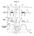
- FIG. 4 is a diagram illustrating a relationship between the injection pulse output from the ECU 120, timing of a voltage supply to the fuel injection valve, timing of an excitation current supply to the fuel injection valve, and a behavior of the movable core 102.
- the embodiment examples a split injection of splitting fuel mass per a one-time injection stroke into several times such as in a first fuel injection period (equivalent to a width of a first fuel injection pulse 408) and a second fuel injection period (equivalent to a width of a second fuel injection pulse 410).
- a high voltage 401 to be a drive voltage for the fuel injection valve is applied to the electromagnetic coil 105 from a high-voltage source of the EDU 121.
- the high voltage 401 is generated by boosting a battery voltage VB so as to be higher than the battery voltage VB. This makes the supply of a drive current 404 to the electromagnetic coil 105.
- the application of the high voltage 401 is terminated to decrease the applied voltage to 0 V or lower and decrease a value of the drive current 404.
- the drive circuit 121 provides a battery voltage application 402 by means of switching and controls to obtain a predetermined valve current value 405 capable of holding in the valve open state. Subsequently, when the injection pulse 408 is turned off at t 30 , the voltage to the electromagnetic coil is decreased to 0 V or lowers to reduce the excitation current.
- the movable core 102 starts a valve closing sequence. Subsequently, before the displacement of the movable core 102 is reduced to 0 (zero) or less (namely, before the timing t 32 where the valve plug 114 sits on the valve seat 118, that is, before the timing when the engagement portion 301 of the movable core 102 is disengaged from the engagement portion 302 of the valve plug 114 to allow the movable core 102 to initiate its relative displacement in the valve closing direction with respect to the valve plug 114), an injection pulse 409 is turned on at t 31 , and thereby causing the high-voltage source to apply a high voltage 403 and supplying an intermediate current 407 to the electromagnetic coil 105.
- Such an intermediate current has a level of not opening the valve and is supplied to the electromagnetic coil 105 for the following reason. That is, there is occurred a magnetic time lag between the instant when the drive voltage 401 is applied to the electromagnetic coil 105 and the instant when the magnetic attractive force is generated between the magnetic core 107 and the movable core 102. Therefore, in view of such circumstances, provide that the intermediate voltage is applied before the displacement of the movable core 102 decreases to 0 (zero) or less (namely just before the valve plug sits on the valve seat), the motion of the movable core 102 can be quickly attenuated at timing t 32 and later (the timing t 32 is equivalent to a point in time when the valve plug 114 sits on the valve seat118).
- the timing t 31 of initiation of the immediate current 407 is set after turning off the electromagnetic coil-voltage application in the first fuel injection period (equivalent to the width of the fuel injection pulse 408) before a first point in time (t 32 ) when the valve plug 114 sits on the valve seat 118 (namely, the timing t 31 of initiation of the immediate current 407 is in between termination t 30 of the voltage application in the first fuel injection period and a point of time t 32 when the valve plug 115 sits on the valve seat 118; in other words, the timing t 31 of initiation of the immediate current 407 is in between termination of the first injection pulse 408 and a point of time when the valve plug 115 sits on the valve seat 118).
- the intermediate current 407 is used to quickly attenuate the motion of the movable core 102 at timing t 32 and later.
- the timing t 31 of the intermediate current 407 it is preferable to set the timing t 31 as early as possible between a point of time t 30 and a point of time t 32 , for example as illustrated in FIG. 4 , set t 31 at a point of time equal to or earlier than a point of time when a displacement of the valve reaches a half amount of an entire displacement thereof in the valve closing direction.
- the valve closing speed of the valve plug 114 can be decreased effectively, so it possible to reduce not only a drive sound, which is emitted when the valve plug 114 sits on the valve seat 118 with impact, but also wear of the valve seat.
- the time Tr required for the movable core 102 to come to rest can be further shortened.
- the intermediate current is supplied for a predetermined period of time, and then the injection pulse 408 is turned off to shut off (terminate) the supply of the intermediate current 407 to the electromagnetic coil 105.
- the supply of the intermediate current 407 needs to terminate before the elapse of half a time period Td between the first point t 32 in time and a second point t 35 in time when initiating an application of a drive voltage for opening the valve in the second fuel injection period (equivalent to a width of the second injection pulse 410).
- the first point 32 in time is a point in time when the displacement of the movable core 102 decreases to 0 (zero) or the valve plug 114 comes into contact with the valve seat 118.
- the second point t 35 in time is a point in time when the supply of the drive voltage is initiated for the second fuel injection subsequent to the first fuel injection in the split injection.
- the voltage application 403 for supplying the intermediate current 407 terminates before a magnitude of the intermediate current 407 increases as needed to separate the valve plug 114 on the valve seat 118 from the valve seat 118.
- each of the injection pulse 408 and the injection pulse 409 includes two kinds of voltage application periods, one of which is a boosted voltage application period of applying the electromagnetic coil 105 with a voltage (equivalent to the drive voltage 401 for a valve open) boosted by a boost circuit 514 (refer to FIG. 5 ), and the other of which is a power source-voltage application period of applying the electromagnetic coil 105 with a voltage 402 of a battery (power source for holding the valve-open) by means switching subsequent to the boosted voltage application period.
- a maximum value of the intermediate current 407 is set to be greater than a maximum value of a current 405 supplied by the voltage 402 of the battery (power source) in the power source-voltage application period, and set to be smaller than a maximum value of a current 404 by the boosted voltage 401 in the boosted voltage application period.
- the injection pulse 408 is a pulse for a first fuel injection period
- an injection pulse 410 is a pulse for a second fuel injection period.
- the injection pulse 409 is an injection pulse for the intermediate current being supplied in between the first fuel injection period and the second fuel injection period.
- the injection pulse 409 does not cause the valve plug 114 to perform a valve opening operation.
- the valve plug 114 has not completely returned to a valve closing position (namely has not sat on the valve seat yet), so a fuel injection itself terminates with a small delay after the termination of the injection pulse 408. This also holds true for the second fuel injection period.
- the injection pulse 408 for the first fuel injection period and the injection pulse 410 for the second fuel injection period are output during a single injection stroke.
- the present embodiment is configured such that the fuel mass provided per one-time injection stroke is split into a plurality of injections, which are provided by at least the injection pulses 408 and 409.
- the term "one-time injection stroke” denotes one combustion cycle (which includes an intake stroke, a compression stroke, an explosion stroke, and an exhaust stroke when a four-cycle engine is employed).
- FIG. 5 is a diagram illustrating the circuit conf iguration f or driving the fuel injection valve.
- a CPU 501 which is included, for instance, in the ECU 120, computes an appropriate injection pulse width Ti and injection timing in accordance with the operating conditions for the internal combustion engine and outputs an injection pulse Ti to a drive IC 502 of the fuel injection valve through a communication line 504. Subsequently, the drive IC 502 selectively turns on or off switching elements 505, 506, 507 to supply the drive current to the fuel injection valve 515.
- the switching element 505 is connected between a high-voltage source VH, which outputs a higher voltage than a voltage source VB whose voltage is input into the drive circuit 121, and a high-voltage terminal of the fuel injection valve 515.
- the switching elements 505, 506, 507 include, for instance, an FET or other transistor.
- the high-voltage source VH outputs a voltage of 60 V. This voltage is generated by boosting the battery voltage with the booster circuit 514.
- the booster circuit 514 includes, for instance, a DC/DC converter.
- the switching element 507 is connected between a low-voltage source VB and a high-voltage terminal of the fuel injection valve 515.
- the output of the low-voltage source VB is, for instance, a battery voltage of 12 V.
- the switching element 506 is connected between a ground potential and a low-voltage terminal of the fuel injection valve 515.
- the drive IC 502 causes current detection resistors 508, 512, 513 to detect the value of a current flowing in the fuel injection valve 515 and selectively turns on or off the switching elements 505, 506, 507 in accordance with the detected current value to generate a desired drive current. Diodes 509, 510 are employed to shut off the supply of the current.
- the CPU 501 communicates with the drive IC 502 through a communication line 503 and can change the drive current, which is to be generated by the drive IC 502, in accordance with the operating conditions and the pressure of fuel to be supplied to the fuel injection valve 515.
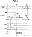
- FIG. 6 is a diagram illustrating the injectionpulse output from the CPU 501, the drive current, and timings of the switching element (SW) 505, the switching element (SW) 506, and the switching element (SW) 507.
- the current supplied to the fuel injection valve 515 then quickly decreases from the peak current value Ipeak as indicated at 601 to a holding current 602.
- the switching element 506 being turned on during a period of transition from the peak current value Ipeak to the holding current 602
- the current based on counter-electromotive force energy flows toward the ground potential and gradually decreases.
- the switching element 506 is turned on and the switching element 507 is controlled so as to repeatedly switch between ON and OFF, so retain the holding current 602 is retained as it is.
- the injection pulse 604 subsequently is turned off, the switching elements 506 and 507 both are turn off to decrease the current 602.
- an injection pulse 605 is generated after the elapse of a predetermined period of time, the switching elements 505, 506 both is turned on, so the high-voltage source VH supplies an intermediate current 603 to the fuel injection valve 515. Subsequently, the intermediate current 603 is supplied to the electromagnetic coil for a predetermined period in time, and then, upon an injection pulse-width in which the injection pulse is turned off at predetermined timing t 64 , the switching elements 505 and 506 both are turned off to quickly decrease the intermediate current 603.
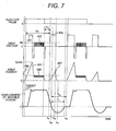
- FIG. 7 is a diagram illustrating a relationship between the injection pulse output from the ECU 120, timing of the drive voltage supply to the fuel injection valve, timing of the drive current supply to the fuel injection valve, and a behavior of the movable core 102.
- the second embodiment differs from the first embodiment in that the high voltage 403 for supplying the intermediate current 407 is applied by using the drive circuit 121 instead of the injection pulse width from the ECU 120.
- the timing t 41 of applying the high voltage 403 is controlled in accordance with the elapsed time T i1 from initiation of the injection pulse or with the elapsed time T i2 from termination of the injection pulse, the same advantage is obtained as in the first embodiment in which the intermediate current 407 is controlled by the injection pulse.
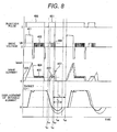
- FIG. 8 is a diagram illustrating a relationship between the injection pulse output from the ECU 120 according to the third embodiment, timing of the drive voltage supply to the fuel injection valve, timing of the drive current (excitation current) supply to the fuel injection valve, and a behavior of the movable core 102.
- elements identical with those in FIG. 4 are designated by the same reference numerals as the corresponding elements.
- the drive current and the displacement of the movable core that are represented in FIG. 4 are indicated by dotted lines to clarify the differences from the first embodiment.
- the third embodiment differs from the first embodiment in that the injection pulse 801 is turned on at a timing earlier than the current resupply timing t 31 illustrated in FIG. 4 to apply the battery voltage VB from the voltage source and supply the intermediate current 803 to the electromagnetic coil 105.
- the magnetic attractive force can be generated again during an interval between the instant when the injection pulse 801 is turned off and the instant when the magnetic flux in the magnetic circuit completely disappears. This makes it possible to reduce the magnetic time lag between the instant when the intermediate current 803 is supplied and the instant when the magnetic attractive force is generated.
- the kinetic energy of the movable core 102 after the valve-closing can be reduced. This makes it possible to reduce the time Tr required for the movable core 102 to come to rest.
- supplying the intermediate current 803 at a stage earlier than the timing t 31 decreases the valve closing speed of the valve plug 114. This reduces not only a drive noise being emitted when the valve plug 114 sits on the valve seat 118 with impact, but also wear of the valve seat.
- the drive circuit 121 Upon the intermediate current 803 reaching a predetermined current value after a point t 81 in time when the intermediate current 803 is supplied, the drive circuit 121 applies the battery voltage by means of switching as indicated at 802 and exercises control so as to obtain a predetermined current value 804.
- the intermediate current 803 holding the predetermined current value 804 for a certain period the magnetic attractive force generated between the stationary core 107 and the movable core 102 can be maintained constant.
- the time Tr required for the movable core 102 to come to rest can be accurately controlled.
- the power consumption of the drive circuit 121 is proportional to the square of the value of the current supplied to the electromagnetic coil 105, the consumption of current can be reduced when the supply of the intermediate current 803 is achieved by applying the battery voltage VB.
- the high-voltage source VH supplies a current to the electromagnetic coil 105 in a situation where the high-voltage source VH is configured to boost the battery voltage VB by storing electric charge into a capacitor
- the voltage value of the high-voltage source VH decreases with time.
- the voltage value of the high-voltage source is recovered to normal after a lapse of the predetermined time.
- the time required for current build-up may increase.
- the intermediate current 803 is supplied to the electromagnetic coil 105 by application of the battery voltage VB, the voltage value of the high-voltage source VH can be recovered to normal with ease at point t 85 when the drive voltage is supplied to perform the next split injection. As a result, the current can be steadily supplied to the electromagnetic coil 105.
Landscapes
- Engineering & Computer Science (AREA)
- Chemical & Material Sciences (AREA)
- Combustion & Propulsion (AREA)
- Mechanical Engineering (AREA)
- General Engineering & Computer Science (AREA)
- Fuel-Injection Apparatus (AREA)
- Electrical Control Of Air Or Fuel Supplied To Internal-Combustion Engine (AREA)
Applications Claiming Priority (1)
| Application Number | Priority Date | Filing Date | Title |
|---|---|---|---|
| JP2011039180A JP5492806B2 (ja) | 2011-02-25 | 2011-02-25 | 電磁式燃料噴射弁の駆動装置 |
Publications (2)
| Publication Number | Publication Date |
|---|---|
| EP2492479A1 true EP2492479A1 (fr) | 2012-08-29 |
| EP2492479B1 EP2492479B1 (fr) | 2014-07-30 |
Family
ID=45656596
Family Applications (1)
| Application Number | Title | Priority Date | Filing Date |
|---|---|---|---|
| EP20120156796 Not-in-force EP2492479B1 (fr) | 2011-02-25 | 2012-02-24 | Dispositif de commande de soupape d'injection de carburant électromagnétique |
Country Status (4)
| Country | Link |
|---|---|
| US (1) | US8960157B2 (fr) |
| EP (1) | EP2492479B1 (fr) |
| JP (1) | JP5492806B2 (fr) |
| CN (1) | CN102650241B (fr) |
Cited By (1)
| Publication number | Priority date | Publication date | Assignee | Title |
|---|---|---|---|---|
| CN110959068A (zh) * | 2017-07-28 | 2020-04-03 | 株式会社电装 | 燃料喷射控制装置以及燃料喷射控制方法 |
Families Citing this family (34)
| Publication number | Priority date | Publication date | Assignee | Title |
|---|---|---|---|---|
| DE102011075270A1 (de) * | 2011-05-04 | 2012-11-08 | Continental Automotive Gmbh | Verfahren und Vorrichtung zum Steuern eines Ventils |
| JP5572604B2 (ja) * | 2011-08-31 | 2014-08-13 | 日立オートモティブシステムズ株式会社 | 燃料噴射弁の制御装置 |
| DE102012207406A1 (de) * | 2012-05-04 | 2013-11-07 | Robert Bosch Gmbh | Ventil zum Zumessen von Fluid |
| DE102012211994B4 (de) * | 2012-07-10 | 2024-08-08 | Vitesco Technologies GmbH | Steuergerät zur Ansteuerung zumindest einen Kraftstoffeinspritzventils und Schaltungsanordnung mit einem solchen Steuergerät |
| JP5874607B2 (ja) | 2012-11-05 | 2016-03-02 | 株式会社デンソー | 燃料噴射制御装置および燃料噴射システム |
| JP5772788B2 (ja) * | 2012-11-05 | 2015-09-02 | 株式会社デンソー | 燃料噴射制御装置および燃料噴射システム |
| JP5880872B2 (ja) * | 2013-01-14 | 2016-03-09 | 株式会社デンソー | 燃料噴射弁及び燃料噴射装置 |
| JP5849975B2 (ja) * | 2013-02-25 | 2016-02-03 | 株式会社デンソー | 燃料噴射制御装置および燃料噴射システム |
| DE102013203130A1 (de) * | 2013-02-26 | 2014-08-28 | Robert Bosch Gmbh | Verfahren zur Steuerung eines Einspritzvorgangs eines Magnetinjektors |
| DE112014002349B4 (de) | 2013-05-10 | 2019-12-05 | Denso Corporation | Kraftstoffeinspritzsteuervorrichtung und Kraftstoffeinspritzsystem |
| EP3597899B1 (fr) * | 2013-07-29 | 2026-01-21 | Astemo, Ltd. | Dispositif d'entraînement pour dispositif d'injection de carburant et système d'injection de carburant |
| US9347395B2 (en) * | 2013-08-22 | 2016-05-24 | GM Global Technology Operations LLC | Method for improving closely-spaced multiple-injection performance from solenoid actuated fuel injectors |
| US9441594B2 (en) * | 2013-08-27 | 2016-09-13 | Caterpillar Inc. | Valve actuator assembly with current trim and fuel injector using same |
| JP6318575B2 (ja) * | 2013-11-21 | 2018-05-09 | 株式会社デンソー | 燃料噴射制御装置および燃料噴射システム |
| JP6233080B2 (ja) | 2014-02-10 | 2017-11-22 | 株式会社デンソー | 燃料噴射制御装置 |
| JP6413582B2 (ja) * | 2014-10-03 | 2018-10-31 | 株式会社デンソー | 内燃機関の制御装置 |
| DE102015217955A1 (de) * | 2014-10-21 | 2016-04-21 | Robert Bosch Gmbh | Vorrichtung zur Steuerung von wenigstens einem schaltbaren Ventil |
| JP6511266B2 (ja) * | 2014-12-25 | 2019-05-15 | 日立オートモティブシステムズ株式会社 | 燃料噴射弁制御装置 |
| JP6286714B2 (ja) * | 2015-05-15 | 2018-03-07 | 株式会社ケーヒン | 燃料噴射制御装置 |
| JP6263811B2 (ja) * | 2015-05-15 | 2018-01-24 | 株式会社ケーヒン | 燃料噴射制御装置 |
| DE102015209783A1 (de) * | 2015-05-28 | 2016-12-01 | Robert Bosch Gmbh | Verfahren zur Ansteuerung eines Kraftstoffinjektors |
| JP6477301B2 (ja) * | 2015-06-29 | 2019-03-06 | 株式会社デンソー | 噴射制御装置 |
| JP6107913B2 (ja) * | 2015-10-07 | 2017-04-05 | 株式会社デンソー | 燃料噴射制御装置および燃料噴射システム |
| JP6557608B2 (ja) * | 2016-01-22 | 2019-08-07 | 日立オートモティブシステムズ株式会社 | 燃料噴射装置の制御装置 |
| US10210977B2 (en) * | 2016-06-03 | 2019-02-19 | Lam Research Corporation | Valve operation booster |
| JP6294422B2 (ja) * | 2016-09-08 | 2018-03-14 | 日立オートモティブシステムズ株式会社 | 燃料噴射装置の駆動装置および燃料噴射システム |
| DE102016219890B3 (de) * | 2016-10-12 | 2017-08-03 | Continental Automotive Gmbh | Verfahren und Steuereinrichtung zum Steuern eines Schaltventils |
| FR3061746B1 (fr) * | 2017-01-10 | 2020-09-25 | Continental Automotive France | Procede de correction d'une duree d'injection de carburant dans un cylindre de moteur thermique de vehicule automobile |
| JP6856387B2 (ja) * | 2017-01-20 | 2021-04-07 | 日立Astemo株式会社 | 燃料噴射装置の駆動装置 |
| JP6844501B2 (ja) * | 2017-10-31 | 2021-03-17 | 株式会社デンソー | 燃料噴射弁の制御装置、及び燃料噴射弁の制御方法 |
| CN108656741B (zh) * | 2018-05-21 | 2020-06-02 | 苏州华兴源创科技股份有限公司 | 一种利用电磁阀控制的喷墨打点装置和方法 |
| US11480129B2 (en) * | 2021-02-19 | 2022-10-25 | Caterpillar Inc. | Fuel system and fuel injector control strategy for stabilized injection control valve closing |
| JP2025185940A (ja) * | 2024-06-11 | 2025-12-23 | Astemo株式会社 | 燃料噴射制御装置及び燃料噴射制御方法 |
| CN119393246B (zh) * | 2024-10-30 | 2025-10-24 | 潍柴动力股份有限公司 | 一种甲醇喷射器控制方法及相关装置 |
Citations (4)
| Publication number | Priority date | Publication date | Assignee | Title |
|---|---|---|---|---|
| EP0727566A2 (fr) * | 1995-02-15 | 1996-08-21 | Toyota Jidosha Kabushiki Kaisha | Un dispositif d'entraînement de soupape utilisant une bobine électromagnétique pour déplacer un corps de soupape avec moins de bruit |
| JP2002115591A (ja) | 2000-10-04 | 2002-04-19 | Nissan Motor Co Ltd | 内燃機関の燃料噴射装置 |
| EP1909009A2 (fr) * | 2006-10-06 | 2008-04-09 | Denso Corporation | Dispositif électrovanne conçu pour garantir une grande réactivité de l'action de la vanne |
| EP1990526A2 (fr) * | 2007-05-09 | 2008-11-12 | Hitachi, Ltd. | Dispositif d'injecteur de carburant électromagnétique |
Family Cites Families (16)
| Publication number | Priority date | Publication date | Assignee | Title |
|---|---|---|---|---|
| FR2345595A1 (fr) * | 1976-03-26 | 1977-10-21 | Bosch Gmbh Robert | Installation pour la commande, avec un courant regle, d'organes de manoeuvre electromagnetiques |
| US5445128A (en) * | 1993-08-27 | 1995-08-29 | Detroit Diesel Corporation | Method for engine control |
| JP3613885B2 (ja) * | 1996-05-24 | 2005-01-26 | 国産電機株式会社 | 内燃機関用インジェクタの駆動制御方法及び駆動制御装置 |
| US5865371A (en) | 1996-07-26 | 1999-02-02 | Siemens Automotive Corporation | Armature motion control method and apparatus for a fuel injector |
| JP3534167B2 (ja) * | 1998-05-25 | 2004-06-07 | 国産電機株式会社 | インジェクタ駆動方法及び駆動回路 |
| JP3527857B2 (ja) * | 1998-12-25 | 2004-05-17 | 株式会社日立製作所 | 燃料噴射装置及び内燃機関 |
| US6705277B1 (en) * | 2000-07-13 | 2004-03-16 | Caterpillar Inc | Method and apparatus for delivering multiple fuel injections to the cylinder of an engine wherein the pilot fuel injection occurs during the intake stroke |
| US6467452B1 (en) * | 2000-07-13 | 2002-10-22 | Caterpillar Inc | Method and apparatus for delivering multiple fuel injections to the cylinder of an internal combustion engine |
| JP2002364768A (ja) * | 2001-06-07 | 2002-12-18 | Denso Corp | 電磁弁駆動装置 |
| JP2003120848A (ja) * | 2001-10-18 | 2003-04-23 | Bosch Automotive Systems Corp | 電磁弁駆動制御方法及び電磁弁駆動制御装置 |
| US6766788B2 (en) * | 2002-01-31 | 2004-07-27 | Visteon Global Technologies, Inc. | Pre-charging strategy for fuel injector fast opening |
| DE60313667T2 (de) * | 2002-12-10 | 2007-12-27 | Mikuni Corp. | Steuerverfahren und vorrichtung zur kraftstoffeinspritzung |
| JP3810372B2 (ja) * | 2003-01-28 | 2006-08-16 | 三菱電機株式会社 | 燃料噴射弁の制御装置 |
| US6935580B2 (en) * | 2003-02-10 | 2005-08-30 | Caterpillar Inc | Valve assembly having multiple rate shaping capabilities and fuel injector using same |
| JP4148127B2 (ja) * | 2003-12-12 | 2008-09-10 | 株式会社デンソー | 燃料噴射装置 |
| JP4474423B2 (ja) | 2007-01-12 | 2010-06-02 | 日立オートモティブシステムズ株式会社 | 内燃機関制御装置 |
-
2011
- 2011-02-25 JP JP2011039180A patent/JP5492806B2/ja active Active
-
2012
- 2012-02-10 CN CN201210030585.2A patent/CN102650241B/zh not_active Expired - Fee Related
- 2012-02-23 US US13/403,506 patent/US8960157B2/en active Active
- 2012-02-24 EP EP20120156796 patent/EP2492479B1/fr not_active Not-in-force
Patent Citations (5)
| Publication number | Priority date | Publication date | Assignee | Title |
|---|---|---|---|---|
| EP0727566A2 (fr) * | 1995-02-15 | 1996-08-21 | Toyota Jidosha Kabushiki Kaisha | Un dispositif d'entraînement de soupape utilisant une bobine électromagnétique pour déplacer un corps de soupape avec moins de bruit |
| JP2002115591A (ja) | 2000-10-04 | 2002-04-19 | Nissan Motor Co Ltd | 内燃機関の燃料噴射装置 |
| EP1909009A2 (fr) * | 2006-10-06 | 2008-04-09 | Denso Corporation | Dispositif électrovanne conçu pour garantir une grande réactivité de l'action de la vanne |
| EP1990526A2 (fr) * | 2007-05-09 | 2008-11-12 | Hitachi, Ltd. | Dispositif d'injecteur de carburant électromagnétique |
| JP2008280876A (ja) | 2007-05-09 | 2008-11-20 | Hitachi Ltd | 電磁式燃料噴射弁の制御回路 |
Cited By (3)
| Publication number | Priority date | Publication date | Assignee | Title |
|---|---|---|---|---|
| CN110959068A (zh) * | 2017-07-28 | 2020-04-03 | 株式会社电装 | 燃料喷射控制装置以及燃料喷射控制方法 |
| DE112018003842B4 (de) * | 2017-07-28 | 2020-08-13 | Denso Corporation | Kraftstoffeinspritz-Steuervorrichtung und Verfahren zur Steuerung der Kraftstoffeinspritzung |
| CN110959068B (zh) * | 2017-07-28 | 2022-03-15 | 株式会社电装 | 燃料喷射控制装置以及燃料喷射控制方法 |
Also Published As
| Publication number | Publication date |
|---|---|
| US8960157B2 (en) | 2015-02-24 |
| CN102650241A (zh) | 2012-08-29 |
| JP2012177303A (ja) | 2012-09-13 |
| CN102650241B (zh) | 2015-01-07 |
| US20120216783A1 (en) | 2012-08-30 |
| EP2492479B1 (fr) | 2014-07-30 |
| JP5492806B2 (ja) | 2014-05-14 |
Similar Documents
| Publication | Publication Date | Title |
|---|---|---|
| EP2492479B1 (fr) | Dispositif de commande de soupape d'injection de carburant électromagnétique | |
| US10900435B2 (en) | Drive unit of fuel injection device | |
| US9714626B2 (en) | Drive device for fuel injection device | |
| US10082117B2 (en) | Fuel injection device | |
| US7774126B2 (en) | Electromagnetic fuel injection valve device | |
| JP6708741B2 (ja) | 燃料噴射装置の制御装置 | |
| WO2013031422A1 (fr) | Appareil de commande pour soupape d'injection de carburant | |
| US10662886B2 (en) | Control device for fuel injection device | |
| WO2018135219A1 (fr) | Dispositif d'entraînement pour dispositif d'injection de carburant | |
| Lu et al. | Impact of control methods on dynamic characteristic of high speed solenoid injectors | |
| JP7177458B2 (ja) | 燃料噴射装置を制御する制御装置 | |
| JP5865409B2 (ja) | 電磁式燃料噴射弁の駆動装置 | |
| JP6561184B2 (ja) | 燃料噴射装置の駆動装置 | |
| JP2015206371A (ja) | 電磁弁装置の駆動装置 | |
| WO2020100485A1 (fr) | Dispositif de commande pour appareil d'injection de carburant | |
| JP2018080582A (ja) | 燃料噴射装置の制御装置 | |
| JP2014156867A (ja) | 電磁弁装置の駆動装置 |
Legal Events
| Date | Code | Title | Description |
|---|---|---|---|
| PUAI | Public reference made under article 153(3) epc to a published international application that has entered the european phase |
Free format text: ORIGINAL CODE: 0009012 |
|
| 17P | Request for examination filed |
Effective date: 20120323 |
|
| AK | Designated contracting states |
Kind code of ref document: A1 Designated state(s): AL AT BE BG CH CY CZ DE DK EE ES FI FR GB GR HR HU IE IS IT LI LT LU LV MC MK MT NL NO PL PT RO RS SE SI SK SM TR |
|
| AX | Request for extension of the european patent |
Extension state: BA ME |
|
| GRAP | Despatch of communication of intention to grant a patent |
Free format text: ORIGINAL CODE: EPIDOSNIGR1 |
|
| RIC1 | Information provided on ipc code assigned before grant |
Ipc: F02D 41/20 20060101AFI20140113BHEP Ipc: F02D 41/40 20060101ALN20140113BHEP |
|
| INTG | Intention to grant announced |
Effective date: 20140212 |
|
| RIN1 | Information on inventor provided before grant (corrected) |
Inventor name: KUSAKABE, RYO Inventor name: ABE, MOTOYUKI Inventor name: MAYUZUMI, TAKUYA Inventor name: MAEKAWA, NORIYUKI Inventor name: ISHIKAWA, TOHRU Inventor name: EHARA, HIDEHARU |
|
| GRAS | Grant fee paid |
Free format text: ORIGINAL CODE: EPIDOSNIGR3 |
|
| GRAA | (expected) grant |
Free format text: ORIGINAL CODE: 0009210 |
|
| AK | Designated contracting states |
Kind code of ref document: B1 Designated state(s): AL AT BE BG CH CY CZ DE DK EE ES FI FR GB GR HR HU IE IS IT LI LT LU LV MC MK MT NL NO PL PT RO RS SE SI SK SM TR |
|
| REG | Reference to a national code |
Ref country code: GB Ref legal event code: FG4D |
|
| REG | Reference to a national code |
Ref country code: CH Ref legal event code: EP |
|
| REG | Reference to a national code |
Ref country code: AT Ref legal event code: REF Ref document number: 680120 Country of ref document: AT Kind code of ref document: T Effective date: 20140815 |
|
| REG | Reference to a national code |
Ref country code: IE Ref legal event code: FG4D |
|
| REG | Reference to a national code |
Ref country code: DE Ref legal event code: R096 Ref document number: 602012002546 Country of ref document: DE Effective date: 20140911 |
|
| REG | Reference to a national code |
Ref country code: AT Ref legal event code: MK05 Ref document number: 680120 Country of ref document: AT Kind code of ref document: T Effective date: 20140730 |
|
| REG | Reference to a national code |
Ref country code: NL Ref legal event code: VDEP Effective date: 20140730 |
|
| REG | Reference to a national code |
Ref country code: LT Ref legal event code: MG4D |
|
| PG25 | Lapsed in a contracting state [announced via postgrant information from national office to epo] |
Ref country code: LT Free format text: LAPSE BECAUSE OF FAILURE TO SUBMIT A TRANSLATION OF THE DESCRIPTION OR TO PAY THE FEE WITHIN THE PRESCRIBED TIME-LIMIT Effective date: 20140730 Ref country code: ES Free format text: LAPSE BECAUSE OF FAILURE TO SUBMIT A TRANSLATION OF THE DESCRIPTION OR TO PAY THE FEE WITHIN THE PRESCRIBED TIME-LIMIT Effective date: 20140730 Ref country code: BG Free format text: LAPSE BECAUSE OF FAILURE TO SUBMIT A TRANSLATION OF THE DESCRIPTION OR TO PAY THE FEE WITHIN THE PRESCRIBED TIME-LIMIT Effective date: 20141030 Ref country code: SE Free format text: LAPSE BECAUSE OF FAILURE TO SUBMIT A TRANSLATION OF THE DESCRIPTION OR TO PAY THE FEE WITHIN THE PRESCRIBED TIME-LIMIT Effective date: 20140730 Ref country code: GR Free format text: LAPSE BECAUSE OF FAILURE TO SUBMIT A TRANSLATION OF THE DESCRIPTION OR TO PAY THE FEE WITHIN THE PRESCRIBED TIME-LIMIT Effective date: 20141031 Ref country code: PT Free format text: LAPSE BECAUSE OF FAILURE TO SUBMIT A TRANSLATION OF THE DESCRIPTION OR TO PAY THE FEE WITHIN THE PRESCRIBED TIME-LIMIT Effective date: 20141202 Ref country code: FI Free format text: LAPSE BECAUSE OF FAILURE TO SUBMIT A TRANSLATION OF THE DESCRIPTION OR TO PAY THE FEE WITHIN THE PRESCRIBED TIME-LIMIT Effective date: 20140730 Ref country code: NO Free format text: LAPSE BECAUSE OF FAILURE TO SUBMIT A TRANSLATION OF THE DESCRIPTION OR TO PAY THE FEE WITHIN THE PRESCRIBED TIME-LIMIT Effective date: 20141030 |
|
| PG25 | Lapsed in a contracting state [announced via postgrant information from national office to epo] |
Ref country code: IS Free format text: LAPSE BECAUSE OF FAILURE TO SUBMIT A TRANSLATION OF THE DESCRIPTION OR TO PAY THE FEE WITHIN THE PRESCRIBED TIME-LIMIT Effective date: 20141130 Ref country code: LV Free format text: LAPSE BECAUSE OF FAILURE TO SUBMIT A TRANSLATION OF THE DESCRIPTION OR TO PAY THE FEE WITHIN THE PRESCRIBED TIME-LIMIT Effective date: 20140730 Ref country code: HR Free format text: LAPSE BECAUSE OF FAILURE TO SUBMIT A TRANSLATION OF THE DESCRIPTION OR TO PAY THE FEE WITHIN THE PRESCRIBED TIME-LIMIT Effective date: 20140730 Ref country code: RS Free format text: LAPSE BECAUSE OF FAILURE TO SUBMIT A TRANSLATION OF THE DESCRIPTION OR TO PAY THE FEE WITHIN THE PRESCRIBED TIME-LIMIT Effective date: 20140730 Ref country code: CY Free format text: LAPSE BECAUSE OF FAILURE TO SUBMIT A TRANSLATION OF THE DESCRIPTION OR TO PAY THE FEE WITHIN THE PRESCRIBED TIME-LIMIT Effective date: 20140730 Ref country code: NL Free format text: LAPSE BECAUSE OF FAILURE TO SUBMIT A TRANSLATION OF THE DESCRIPTION OR TO PAY THE FEE WITHIN THE PRESCRIBED TIME-LIMIT Effective date: 20140730 Ref country code: PL Free format text: LAPSE BECAUSE OF FAILURE TO SUBMIT A TRANSLATION OF THE DESCRIPTION OR TO PAY THE FEE WITHIN THE PRESCRIBED TIME-LIMIT Effective date: 20140730 Ref country code: AT Free format text: LAPSE BECAUSE OF FAILURE TO SUBMIT A TRANSLATION OF THE DESCRIPTION OR TO PAY THE FEE WITHIN THE PRESCRIBED TIME-LIMIT Effective date: 20140730 |
|
| PG25 | Lapsed in a contracting state [announced via postgrant information from national office to epo] |
Ref country code: SK Free format text: LAPSE BECAUSE OF FAILURE TO SUBMIT A TRANSLATION OF THE DESCRIPTION OR TO PAY THE FEE WITHIN THE PRESCRIBED TIME-LIMIT Effective date: 20140730 Ref country code: EE Free format text: LAPSE BECAUSE OF FAILURE TO SUBMIT A TRANSLATION OF THE DESCRIPTION OR TO PAY THE FEE WITHIN THE PRESCRIBED TIME-LIMIT Effective date: 20140730 Ref country code: IT Free format text: LAPSE BECAUSE OF FAILURE TO SUBMIT A TRANSLATION OF THE DESCRIPTION OR TO PAY THE FEE WITHIN THE PRESCRIBED TIME-LIMIT Effective date: 20140730 Ref country code: DK Free format text: LAPSE BECAUSE OF FAILURE TO SUBMIT A TRANSLATION OF THE DESCRIPTION OR TO PAY THE FEE WITHIN THE PRESCRIBED TIME-LIMIT Effective date: 20140730 Ref country code: RO Free format text: LAPSE BECAUSE OF FAILURE TO SUBMIT A TRANSLATION OF THE DESCRIPTION OR TO PAY THE FEE WITHIN THE PRESCRIBED TIME-LIMIT Effective date: 20140730 Ref country code: CZ Free format text: LAPSE BECAUSE OF FAILURE TO SUBMIT A TRANSLATION OF THE DESCRIPTION OR TO PAY THE FEE WITHIN THE PRESCRIBED TIME-LIMIT Effective date: 20140730 |
|
| REG | Reference to a national code |
Ref country code: DE Ref legal event code: R097 Ref document number: 602012002546 Country of ref document: DE |
|
| PLBE | No opposition filed within time limit |
Free format text: ORIGINAL CODE: 0009261 |
|
| STAA | Information on the status of an ep patent application or granted ep patent |
Free format text: STATUS: NO OPPOSITION FILED WITHIN TIME LIMIT |
|
| PG25 | Lapsed in a contracting state [announced via postgrant information from national office to epo] |
Ref country code: BE Free format text: LAPSE BECAUSE OF NON-PAYMENT OF DUE FEES Effective date: 20150228 |
|
| 26N | No opposition filed |
Effective date: 20150504 |
|
| PG25 | Lapsed in a contracting state [announced via postgrant information from national office to epo] |
Ref country code: LU Free format text: LAPSE BECAUSE OF FAILURE TO SUBMIT A TRANSLATION OF THE DESCRIPTION OR TO PAY THE FEE WITHIN THE PRESCRIBED TIME-LIMIT Effective date: 20150224 |
|
| REG | Reference to a national code |
Ref country code: CH Ref legal event code: PL |
|
| PG25 | Lapsed in a contracting state [announced via postgrant information from national office to epo] |
Ref country code: CH Free format text: LAPSE BECAUSE OF NON-PAYMENT OF DUE FEES Effective date: 20150228 Ref country code: LI Free format text: LAPSE BECAUSE OF NON-PAYMENT OF DUE FEES Effective date: 20150228 Ref country code: MC Free format text: LAPSE BECAUSE OF FAILURE TO SUBMIT A TRANSLATION OF THE DESCRIPTION OR TO PAY THE FEE WITHIN THE PRESCRIBED TIME-LIMIT Effective date: 20140730 |
|
| REG | Reference to a national code |
Ref country code: IE Ref legal event code: MM4A |
|
| PG25 | Lapsed in a contracting state [announced via postgrant information from national office to epo] |
Ref country code: SI Free format text: LAPSE BECAUSE OF FAILURE TO SUBMIT A TRANSLATION OF THE DESCRIPTION OR TO PAY THE FEE WITHIN THE PRESCRIBED TIME-LIMIT Effective date: 20140730 |
|
| REG | Reference to a national code |
Ref country code: FR Ref legal event code: PLFP Year of fee payment: 5 |
|
| PG25 | Lapsed in a contracting state [announced via postgrant information from national office to epo] |
Ref country code: IE Free format text: LAPSE BECAUSE OF NON-PAYMENT OF DUE FEES Effective date: 20150224 |
|
| PGFP | Annual fee paid to national office [announced via postgrant information from national office to epo] |
Ref country code: FR Payment date: 20160108 Year of fee payment: 5 Ref country code: GB Payment date: 20160224 Year of fee payment: 5 |
|
| PG25 | Lapsed in a contracting state [announced via postgrant information from national office to epo] |
Ref country code: BE Free format text: LAPSE BECAUSE OF FAILURE TO SUBMIT A TRANSLATION OF THE DESCRIPTION OR TO PAY THE FEE WITHIN THE PRESCRIBED TIME-LIMIT Effective date: 20140730 |
|
| PG25 | Lapsed in a contracting state [announced via postgrant information from national office to epo] |
Ref country code: MT Free format text: LAPSE BECAUSE OF FAILURE TO SUBMIT A TRANSLATION OF THE DESCRIPTION OR TO PAY THE FEE WITHIN THE PRESCRIBED TIME-LIMIT Effective date: 20140730 |
|
| PG25 | Lapsed in a contracting state [announced via postgrant information from national office to epo] |
Ref country code: HU Free format text: LAPSE BECAUSE OF FAILURE TO SUBMIT A TRANSLATION OF THE DESCRIPTION OR TO PAY THE FEE WITHIN THE PRESCRIBED TIME-LIMIT; INVALID AB INITIO Effective date: 20120224 Ref country code: SM Free format text: LAPSE BECAUSE OF FAILURE TO SUBMIT A TRANSLATION OF THE DESCRIPTION OR TO PAY THE FEE WITHIN THE PRESCRIBED TIME-LIMIT Effective date: 20140730 |
|
| PG25 | Lapsed in a contracting state [announced via postgrant information from national office to epo] |
Ref country code: TR Free format text: LAPSE BECAUSE OF FAILURE TO SUBMIT A TRANSLATION OF THE DESCRIPTION OR TO PAY THE FEE WITHIN THE PRESCRIBED TIME-LIMIT Effective date: 20140730 |
|
| GBPC | Gb: european patent ceased through non-payment of renewal fee |
Effective date: 20170224 |
|
| REG | Reference to a national code |
Ref country code: FR Ref legal event code: ST Effective date: 20171031 |
|
| PG25 | Lapsed in a contracting state [announced via postgrant information from national office to epo] |
Ref country code: FR Free format text: LAPSE BECAUSE OF NON-PAYMENT OF DUE FEES Effective date: 20170228 |
|
| PG25 | Lapsed in a contracting state [announced via postgrant information from national office to epo] |
Ref country code: GB Free format text: LAPSE BECAUSE OF NON-PAYMENT OF DUE FEES Effective date: 20170224 |
|
| PG25 | Lapsed in a contracting state [announced via postgrant information from national office to epo] |
Ref country code: MK Free format text: LAPSE BECAUSE OF FAILURE TO SUBMIT A TRANSLATION OF THE DESCRIPTION OR TO PAY THE FEE WITHIN THE PRESCRIBED TIME-LIMIT Effective date: 20140730 |
|
| PG25 | Lapsed in a contracting state [announced via postgrant information from national office to epo] |
Ref country code: AL Free format text: LAPSE BECAUSE OF FAILURE TO SUBMIT A TRANSLATION OF THE DESCRIPTION OR TO PAY THE FEE WITHIN THE PRESCRIBED TIME-LIMIT Effective date: 20140730 |
|
| REG | Reference to a national code |
Ref country code: DE Ref legal event code: R082 Ref document number: 602012002546 Country of ref document: DE Representative=s name: MERH-IP MATIAS ERNY REICHL HOFFMANN PATENTANWA, DE Ref country code: DE Ref legal event code: R081 Ref document number: 602012002546 Country of ref document: DE Owner name: HITACHI ASTEMO, LTD., HITACHINAKA-SHI, JP Free format text: FORMER OWNER: HITACHI AUTOMOTIVE SYSTEMS, LTD., HITACHINAKA-SHI, IBARAKI, JP |
|
| PGFP | Annual fee paid to national office [announced via postgrant information from national office to epo] |
Ref country code: DE Payment date: 20221229 Year of fee payment: 12 |
|
| REG | Reference to a national code |
Ref country code: DE Ref legal event code: R119 Ref document number: 602012002546 Country of ref document: DE |
|
| PG25 | Lapsed in a contracting state [announced via postgrant information from national office to epo] |
Ref country code: DE Free format text: LAPSE BECAUSE OF NON-PAYMENT OF DUE FEES Effective date: 20240903 |
|
| PG25 | Lapsed in a contracting state [announced via postgrant information from national office to epo] |
Ref country code: DE Free format text: LAPSE BECAUSE OF NON-PAYMENT OF DUE FEES Effective date: 20240903 |