EP2484466B1 - Stock feeding apparatus - Google Patents
Stock feeding apparatus Download PDFInfo
- Publication number
- EP2484466B1 EP2484466B1 EP10820354.8A EP10820354A EP2484466B1 EP 2484466 B1 EP2484466 B1 EP 2484466B1 EP 10820354 A EP10820354 A EP 10820354A EP 2484466 B1 EP2484466 B1 EP 2484466B1
- Authority
- EP
- European Patent Office
- Prior art keywords
- work
- spindle
- raw blank
- chuck
- feed rod
- Prior art date
- Legal status (The legal status is an assumption and is not a legal conclusion. Google has not performed a legal analysis and makes no representation as to the accuracy of the status listed.)
- Active
Links
- 210000003414 extremity Anatomy 0.000 claims description 17
- 210000001364 upper extremity Anatomy 0.000 claims description 10
- 238000000034 method Methods 0.000 claims description 6
- 230000007246 mechanism Effects 0.000 description 14
- 238000001179 sorption measurement Methods 0.000 description 2
Images


Classifications
-
- B—PERFORMING OPERATIONS; TRANSPORTING
- B23—MACHINE TOOLS; METAL-WORKING NOT OTHERWISE PROVIDED FOR
- B23B—TURNING; BORING
- B23B13/00—Arrangements for automatically conveying or chucking or guiding stock
- B23B13/12—Accessories, e.g. stops, grippers
- B23B13/123—Grippers, pushers or guiding tubes
-
- B—PERFORMING OPERATIONS; TRANSPORTING
- B23—MACHINE TOOLS; METAL-WORKING NOT OTHERWISE PROVIDED FOR
- B23B—TURNING; BORING
- B23B13/00—Arrangements for automatically conveying or chucking or guiding stock
- B23B13/02—Arrangements for automatically conveying or chucking or guiding stock for turning-machines with a single working-spindle
-
- B—PERFORMING OPERATIONS; TRANSPORTING
- B23—MACHINE TOOLS; METAL-WORKING NOT OTHERWISE PROVIDED FOR
- B23B—TURNING; BORING
- B23B7/00—Automatic or semi-automatic turning-machines with a single working-spindle, e.g. controlled by cams; Equipment therefor; Features common to automatic and semi-automatic turning-machines with one or more working-spindles
-
- B—PERFORMING OPERATIONS; TRANSPORTING
- B23—MACHINE TOOLS; METAL-WORKING NOT OTHERWISE PROVIDED FOR
- B23Q—DETAILS, COMPONENTS, OR ACCESSORIES FOR MACHINE TOOLS, e.g. ARRANGEMENTS FOR COPYING OR CONTROLLING; MACHINE TOOLS IN GENERAL CHARACTERISED BY THE CONSTRUCTION OF PARTICULAR DETAILS OR COMPONENTS; COMBINATIONS OR ASSOCIATIONS OF METAL-WORKING MACHINES, NOT DIRECTED TO A PARTICULAR RESULT
- B23Q7/00—Arrangements for handling work specially combined with or arranged in, or specially adapted for use in connection with, machine tools, e.g. for conveying, loading, positioning, discharging, sorting
- B23Q7/001—Lateral transport of long workpieces
-
- Y—GENERAL TAGGING OF NEW TECHNOLOGICAL DEVELOPMENTS; GENERAL TAGGING OF CROSS-SECTIONAL TECHNOLOGIES SPANNING OVER SEVERAL SECTIONS OF THE IPC; TECHNICAL SUBJECTS COVERED BY FORMER USPC CROSS-REFERENCE ART COLLECTIONS [XRACs] AND DIGESTS
- Y10—TECHNICAL SUBJECTS COVERED BY FORMER USPC
- Y10T—TECHNICAL SUBJECTS COVERED BY FORMER US CLASSIFICATION
- Y10T82/00—Turning
- Y10T82/25—Lathe
- Y10T82/2514—Lathe with work feeder or remover
- Y10T82/2516—Magazine type
-
- Y—GENERAL TAGGING OF NEW TECHNOLOGICAL DEVELOPMENTS; GENERAL TAGGING OF CROSS-SECTIONAL TECHNOLOGIES SPANNING OVER SEVERAL SECTIONS OF THE IPC; TECHNICAL SUBJECTS COVERED BY FORMER USPC CROSS-REFERENCE ART COLLECTIONS [XRACs] AND DIGESTS
- Y10—TECHNICAL SUBJECTS COVERED BY FORMER USPC
- Y10T—TECHNICAL SUBJECTS COVERED BY FORMER US CLASSIFICATION
- Y10T82/00—Turning
- Y10T82/25—Lathe
- Y10T82/2514—Lathe with work feeder or remover
- Y10T82/2521—Bar feeder
Definitions
- the present invention relates to a processing system according to the preamble of claim 1.
- the former work supplying apparatus has a problem that it is not easy to supply short works to the automatic lathe because it does not suppose the short works.
- the latter work supplying apparatus also has a problem that because it just pushes in the works and its smooth supply may become difficult depending on shape, size and others of the works.
- a processing system having the features defined in claim 1.
- the work supplying means has a positioning means for positioning the holding means in holding the work.
- the work moving means is provided movably to an operative position for moving the work to the holding means and to a receding position for permitting the work pushing means to supply the work to the spindle.
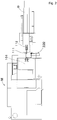
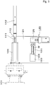
- FIGs. 1 and 2 show a processing system comprising a work supplying apparatus 100 of an embodiment of the invention.
- the processing system is arranged by disposing the work supplying apparatus 100 between an automatic lathe M and a bar feeder B.
- the automatic lathe M is a known automatic lathe and has a rotatable and drivable hollow spindle 101.
- a chuck H is provided at a front extremity of the spindle 101 to machine a work griped by the chuck H by a processing tool.
- the bar feeder B is a known bar feeder through which a lengthy rod member is stored within its body and has a feed rod 112 slidable in an axial direction of the spindle 101 of the automatic lathe M.
- the bar feeder B and the automatic lathe M are disposed so that the feed rod 112 and the spindle 101 are positioned on the same axial line.
- a finger chuck 111 for holding a rear extremity of a rod member is attached at a front extremity of the feed rod 112 to compose a holding means for holding the work by the finger chuck 111.
- the feed rod 112 is movable between a position separated from the spindle 101 behind a rear extremity of the spindle 101 and a position within the spindle 101.
- the bar feeder B is arranged to push and supply the selected rod member into the spindle 101 from the rear extremity of the spindle 101 by moving the feed rod 112 in the axial direction of the spindle 101 while holding the rear extremity of the rod member by the finger chuck 111.
- the processing system inserts and supplies the rod member into the spindle 101 of the automatic lathe M by the bar feeder B from the rear extremity of the spindle 101 as described above so as to be able to process the rod members sequentially by the automatic lathe M.
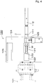
- the work supplying apparatus 100 comprises a reciprocating table 124 provided to be movable forward and backward in a horizontal direction orthogonal to an axial line of the spindle 101 as shown in Fig. 3 .
- a reciprocating table 124 Provided on the reciprocating table 124 are a work receiver 121, a pusher 122, a finger pressing mechanism 125 and a guide member 126.
- the reciprocating table 124 is arranged so as to be able to switch a guiding position in which the guide member 126 is located between the feed rod 112 separated from the spindle 101 and the rear extremity of the spindle 101 and a supplying position in which the work receiver 121 is located therebetween by moving forward and backward as described above.
- the guide member 126 extends in the axial direction of the spindle 101 so as to be able to guide the feed rod 112 in a body with the finger chuck 111 along the axial direction of the spindle 101 when the reciprocating table 124 is in the guiding position.
- the work receiver 121 accommodates a raw blank, i.e., a work formed into a predetermined shape in advance as a short-length work.
- the raw blank is positioned by being accommodated in the work receiver 121 and the work receiver 121 composes a positioning means of the raw blank.
- the raw blank is supplied to the work receiver 121 one by one by a conventionally known parts feeder and the like in the present embodiment.
- the pusher 122 is composed of a cylinder disposed so as to face the work receiver 121 and pushes the raw blank out of the work receiver 121 by pressing the raw blank within the work receiver 121 by projecting a piston rod 123 from the cylinder.
- the pusher 122 composes a work moving means for moving the works.
- the pusher 122 pushes the raw blank out of the work receiver 121 as described above and move the raw blank toward the finger chuck 111 when the reciprocating table 124 is in the supplying position facing to the finger chuck 111.
- the raw blank can be inserted and supplied to the finger chuck 111. It is noted that it is possible to arrange so as to use a chuck for gripping the work as a work moving means and so as to move the chuck gripping the work relatively with the finger chuck 111.
- the finger pressing mechanism 125 is disposed on the opposite from the pusher 122 across the work receiver 121 and positions the finger chuck 111 by pinching and the like when the reciprocating table 124 is in the supplying position.
- the finger pressing mechanism 125 composes a positioning means for positioning the finger chuck 111 in holding the raw blank by the finger chuck 111.
- the finger pressing mechanism 125 may be what fixes the finger chuck 111 by other mechanisms.
- the pusher 122, the work receiver 121 and the finger pressing mechanism 125 compose a work supplying means 120 for individually supplying the raw blanks to the finger chuck 111.
- the pusher 122, the work receiver 121 and the finger pressing mechanism 125 recede from the position facing to the finger chuck 111 and the guide member 126 faces to the finger chuck 111 by setting the reciprocating table 124 in the guide position, so that it becomes possible to push and supply the raw blank from the rear extremity of the spindle 101 to the spindle 101 by moving the feed rod 112 along the axial direction of the spindle 101 while guiding integrally with the finger chuck 111 by the guide member 126.
- the automatic lathe M can process the raw blank pushed and supplied into the spindle 101 as described above by the tool while gripping the raw blank by the chuck H.
- the feed rod 112 is pulled out of the spindle 101 and is separated from the rear extremity of the spindle 101 after when the chuck H of the spindle 101 grips the raw blank.
- the pusher 122 is placed on the reciprocating table 124 integrally with the work receiver 121 as described above and moves integrally with the reciprocating table 124 due to the forward/backward operation of the reciprocating table 124. Then, the pusher 122 is located at the operation position of pushing and moving the work to the finger chuck 111 when the reciprocating table 124 is in the supplying position and is located at the receding position where the raw blank can be supplied to the spindle 101 by the feed rod 112 when the reciprocating table 124 is in the guide position.
- the feed rod 112 and the finger chuck 111 of the bar feeder B serve both as a work pushing means of the work supplying apparatus 100 for pushing and supplying the raw blank to the spindle 101 from the rear extremity thereof and a holding means provided at the front extremity of the work pushing means so as to hold the raw blank.
- the pusher 122 will not hamper the operation of pushing and inserting the both rod members and raw blanks into the spindle 101 by being moved to the receding position caused by the change of position of the reciprocating table 124 to the guide position, excluding the period of operation for supplying the raw blank to the finger chuck 111.
- the guide member 126 guides the feed rod 112 integrally with the finger chuck 111 and does not hamper the supply of the rod member to the spindle 101. That is, the supply of the rod member to the spindle 101 is carried out smoothly and the operation for pushing and inserting the rod member and the raw blank into the spindle 101 can be smoothly carried out as the feed rod 112 (including the finger chuck 111) is guided by the guide member 126.
- the guide member 126 can also guide the work.
- the processing system can carry out the operation of supplying the rod member to the spindle 101 by the bar feeder B by setting the reciprocating table 124 in the guide position and the operation of supplying the raw blank to the spindle 101 by the feed rod 112 by utilizing the bar feeder B as it is and while changing the positions of the reciprocating table 124 as described above without changing its configuration at all.
- this arrangement it becomes possible to realize the low-cost and space-saving processing system which requires no other loader such as a gantry loader and which can process rod members and short members such as raw blanks.
- a three-claw chuck and others capable of gripping the both normal rod members and raw blanks can be used for the chuck H of the spindle 101. It is noted that while there is a case when a distance between the automatic lathe M and the bar feeder B is widened by providing the work supplying apparatus 100 between the automatic lathe M and the bar feeder B, lengthy rod members can be smoothly supplied to the spindle 101 because the guide member 126 of the work supplying apparatus 100 is located on the axial line.
- the processing system of the present embodiment can be readily realized by adding the work supplying apparatus 100 to a conventional rod member processing system comprising an automatic lathe and a bar feeder.
- the finger chuck 111 may be commonized for raw blanks and for rod members, beside replacing one to which a raw blank is inserted with one which holds a rod member and attaching to the feed rod 112.
- the work receiver 121 may be what can be replaced corresponding raw blanks having different shapes and sizes.
- a driving force for projecting and receding the piston rod 123 of the pusher 122 may be generated by any mechanism such as mechanical, electromagnetic, hydraulic mechanisms.
- the reciprocating table 124 is located in the guide position (receding position of the work moving means) in which the guide member 126 is located between the feed rod 112 separated from the spindle 101 and the rear extremity of the spindle 101 and the finger chuck 111 recedes to a position where the finger chuck 111 can receive the work W supplied to the work receiver 121.
- the piston rod 123 of the pusher 122 also recedes to the spindle side of the short work W such as the raw blank supplied to the work receiver 121.
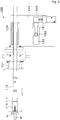
- the reciprocating table 124 moves to the supplying position (operating position of the work moving means) where the work receiver 121 is located between the feed rod 112 separated from the spindle 101 and the rear extremity of the spindle 101 as shown in Fig. 4 and the work receiver 121 confronts to the finger chuck 111.
- the finger pressing mechanism 125 operates to position and fix the finger chuck 111.
- the piston rod 123 of the pusher 122 projects to push the work W in a direction of the finger chuck 111 so as to be held by the finger chuck 111 as shown in Fig. 5 .
- the finger chuck 111 is provided with a slit 113 from its edge in the present embodiment and the work W is held by elasticity thereof when it is inserted to the edge portion of the finger chuck 111.
- the work may be held by holding means having other configuration such as an air or magnetic adsorption mechanism.
- the finger chuck 111 holding the work W recedes to position where the work W is completely taken out of the work receiver 121 as shown in Fig. 6 .
- the reciprocating table 124 moves to the guide (receding position of the work moving means) described above, and the guide member 126 confronts to the finger chuck 111 holding the work W.
- the piston rod 123 of the pusher 122 also recedes so that the next work W can be supplied to the work receiver 121.
- the finger chuck 111 After when the work W is gripped by the chuck H, the finger chuck 111 completes the supply of the work W and returns to the position where the finger chuck 111 can receive the next work W to be supplied to the work receiver 121.
- the operations from the state shown in Fig. 3 to the state shown in Fig. 7 i.e., the operations from when the reciprocating table 124 moves from the position of the guide position to the position (operating position of the work moving means) of the supplying position, the work W is pushed out of the work receiver 121 to be held by the finger chuck 111, the finger chuck 111 recedes and the reciprocating table 124 moves to the position of the guide position (receding position of the work moving means) and until when the guide member 126 confronts to the finger chuck 111 holding the work W, can be carried out in parallel during when the previously supplied work W is processed by being gripped by the chuck H at the front extremity of the spindle 101, so that it becomes possible to shorten a handling time not involved in the processing and to shorten a processing time per each work as a whole.
- the work can be replenished to the work receiver 121 when another work is held by the finger chuck 111 and the reciprocating table 124 is switched to the supplying position, so that the supply of the work W to the finger chuck 111 can be carried smoothly in a short time.
- timing of receding of the piston rod 123 of the pusher 122 and of supplying the next work W to the work receiver 121 are not limited to those described above and may be carried out at appropriate timing within the series of operations.
- the work supplying apparatus 100 of the invention has been explained by exemplifying the case when it is applied to the automatic lathe M in the embodiment described above, the work supplying apparatus 100 may be used in any processing machines, assembling apparatuses and processing apparatuses as long as the system is what supplies works to a hollow spindle having a chuck at a front extremity thereof by pushing the works from a rear extremity thereof.
Landscapes
- Engineering & Computer Science (AREA)
- Mechanical Engineering (AREA)
- Turning (AREA)
- Feeding Of Workpieces (AREA)
- Automatic Assembly (AREA)
Applications Claiming Priority (2)
| Application Number | Priority Date | Filing Date | Title |
|---|---|---|---|
| JP2009229280A JP5457126B2 (ja) | 2009-10-01 | 2009-10-01 | 材料供給装置および加工システム |
| PCT/JP2010/065844 WO2011040235A1 (ja) | 2009-10-01 | 2010-09-14 | 材料供給装置 |
Publications (3)
| Publication Number | Publication Date |
|---|---|
| EP2484466A1 EP2484466A1 (en) | 2012-08-08 |
| EP2484466A4 EP2484466A4 (en) | 2017-01-25 |
| EP2484466B1 true EP2484466B1 (en) | 2020-11-04 |
Family
ID=43826061
Family Applications (1)
| Application Number | Title | Priority Date | Filing Date |
|---|---|---|---|
| EP10820354.8A Active EP2484466B1 (en) | 2009-10-01 | 2010-09-14 | Stock feeding apparatus |
Country Status (8)
| Country | Link |
|---|---|
| US (1) | US8726770B2 (zh) |
| EP (1) | EP2484466B1 (zh) |
| JP (1) | JP5457126B2 (zh) |
| KR (1) | KR101698019B1 (zh) |
| CN (1) | CN102665974B (zh) |
| ES (1) | ES2832500T3 (zh) |
| TW (1) | TWI508800B (zh) |
| WO (1) | WO2011040235A1 (zh) |
Families Citing this family (8)
| Publication number | Priority date | Publication date | Assignee | Title |
|---|---|---|---|---|
| WO2014064847A1 (ja) * | 2012-10-26 | 2014-05-01 | 育良精機株式会社 | 棒材供給機及び送り矢セット |
| JP6207314B2 (ja) | 2013-09-18 | 2017-10-04 | シチズン時計株式会社 | 棒材供給装置および棒材供給装置付きの数値制御工作機械 |
| ITUB20155834A1 (it) * | 2015-11-24 | 2017-05-24 | Cucchi Giovanni & C Srl | Dispositivo e metodo per recuperare e scaricare spezzoni di barre da una macchina utensile |
| JP6807192B2 (ja) * | 2016-08-31 | 2021-01-06 | シチズン時計株式会社 | 工作機械 |
| CN112238226B (zh) * | 2020-10-24 | 2021-08-20 | 上海万众实业股份有限公司 | 一种行星齿轮数控车床出料装置 |
| JP7108148B1 (ja) * | 2021-04-30 | 2022-07-27 | Dmg森精機株式会社 | バーフィーダ及び工作機械 |
| CN113319304A (zh) * | 2021-06-07 | 2021-08-31 | 辽阳奥鹏汽车零部件有限公司 | 一种生产变直径圆棒材料的装置及加工方法 |
| CN113927352A (zh) * | 2021-10-18 | 2022-01-14 | 安徽信息工程学院 | 一种棒材生产线送料装置 |
Family Cites Families (22)
| Publication number | Priority date | Publication date | Assignee | Title |
|---|---|---|---|---|
| US2833545A (en) * | 1957-03-01 | 1958-05-06 | Balas Collet Mfg Company | Pusher device having adjustable tension |
| GB1288385A (zh) * | 1969-02-07 | 1972-09-06 | ||
| DE2537852C3 (de) * | 1975-08-26 | 1978-03-16 | Hagenuk Vormals Neufeldt & Kuhnke Gmbh, 2300 Kiel | Automatische Zuführvorrichtung für Profilstangen an stangenverarbeitenden Drehmaschinen |
| JPS5376283U (zh) * | 1976-11-29 | 1978-06-26 | ||
| JPS5376283A (en) | 1976-12-18 | 1978-07-06 | Mitsubishi Electric Corp | Stopping control of moving body |
| JPS5917101A (ja) | 1982-07-21 | 1984-01-28 | Toshiba Corp | 回転角度検出装置 |
| JPS5917101U (ja) * | 1982-07-26 | 1984-02-02 | 日本特殊陶業株式会社 | 円筒物のチヤツク插入時の案内受具 |
| JPS59156705A (ja) | 1983-02-25 | 1984-09-06 | 松下電工株式会社 | 軽量厚物硬化体の製法 |
| JPS59156705U (ja) * | 1983-11-16 | 1984-10-20 | アヅマ産業株式会社 | 自動加工機の制御装置 |
| JPS627301A (ja) | 1985-06-29 | 1987-01-14 | Toshiba Corp | 浮上式搬送装置 |
| JPH03134196A (ja) * | 1989-10-18 | 1991-06-07 | Mitsui High Tec Inc | リードフレームのめっき装置 |
| US5347896A (en) * | 1992-12-21 | 1994-09-20 | Bausch & Lomb Incorporated | Automated collet loading for the manufacture of contact lenses |
| JPH07328803A (ja) * | 1994-06-02 | 1995-12-19 | Nakamura Tome Precision Ind Co Ltd | 旋盤の材料押込装置 |
| US5505584A (en) * | 1994-07-21 | 1996-04-09 | J. F. Berns Company, Inc. | Air operated loading and unloading device |
| JP3641304B2 (ja) * | 1995-09-07 | 2005-04-20 | 株式会社アルプスツール | フィンガーチャック |
| JP3134196B1 (ja) * | 1999-09-22 | 2001-02-13 | 工業技術院長 | 二重整列ペロブスカイト構造磁気抵抗素子とその使用方法 |
| JP3723465B2 (ja) * | 2001-04-20 | 2005-12-07 | 株式会社育良精機製作所 | 棒材供給方法および棒材供給機 |
| CN100506442C (zh) * | 2003-11-28 | 2009-07-01 | 西铁城控股株式会社 | 数控自动车床的棒材供给装置 |
| EP1637256B1 (en) * | 2004-09-15 | 2014-04-02 | PIETRO CUCCHI S.p.A. | Automatic bar-loader provided with linear sensors of the position of the bar-pusher and automatic lathe including said loader |
| JP2007118163A (ja) * | 2005-10-31 | 2007-05-17 | Star Micronics Co Ltd | 旋盤 |
| JP3134196U (ja) * | 2007-05-09 | 2007-08-09 | 三重精機株式会社 | 旋盤加工機、および、ローディング装置 |
| CN201168788Y (zh) * | 2008-03-31 | 2008-12-24 | 何森权 | 车床棒料自动送进装置的导料装置 |
-
2009
- 2009-10-01 JP JP2009229280A patent/JP5457126B2/ja not_active Expired - Fee Related
-
2010
- 2010-09-14 WO PCT/JP2010/065844 patent/WO2011040235A1/ja active Application Filing
- 2010-09-14 KR KR1020127009671A patent/KR101698019B1/ko active IP Right Grant
- 2010-09-14 ES ES10820354T patent/ES2832500T3/es active Active
- 2010-09-14 CN CN201080043318.8A patent/CN102665974B/zh active Active
- 2010-09-14 EP EP10820354.8A patent/EP2484466B1/en active Active
- 2010-09-14 US US13/499,692 patent/US8726770B2/en active Active
- 2010-09-29 TW TW099132990A patent/TWI508800B/zh active
Non-Patent Citations (1)
| Title |
|---|
| None * |
Also Published As
| Publication number | Publication date |
|---|---|
| EP2484466A1 (en) | 2012-08-08 |
| EP2484466A4 (en) | 2017-01-25 |
| WO2011040235A1 (ja) | 2011-04-07 |
| KR101698019B1 (ko) | 2017-01-20 |
| CN102665974A (zh) | 2012-09-12 |
| TW201113111A (en) | 2011-04-16 |
| TWI508800B (zh) | 2015-11-21 |
| US8726770B2 (en) | 2014-05-20 |
| CN102665974B (zh) | 2015-03-04 |
| KR20120093883A (ko) | 2012-08-23 |
| JP2011073117A (ja) | 2011-04-14 |
| ES2832500T3 (es) | 2021-06-10 |
| JP5457126B2 (ja) | 2014-04-02 |
| US20120186407A1 (en) | 2012-07-26 |
Similar Documents
| Publication | Publication Date | Title |
|---|---|---|
| EP2484466B1 (en) | Stock feeding apparatus | |
| KR101871332B1 (ko) | 판금 벤딩기 | |
| JP2011073117A5 (zh) | ||
| EP2548679B1 (en) | Method for machining using a machine tool | |
| KR20100014597A (ko) | 가이드부시를 구비한 수치제어선반 및 이 수치제어선반을 이용한 공작물의 가공방법 | |
| JPH05208232A (ja) | プレス装置の板状体位置決め移送装置 | |
| EP0385315B1 (en) | Remaining bar material machining method for NC lathe | |
| CN102365151B (zh) | 工件供给装置和具备该工件供给装置的机床 | |
| JP3723465B2 (ja) | 棒材供給方法および棒材供給機 | |
| EP0611620B1 (en) | Device for loading bars into automatic lathes | |
| JP2015211986A (ja) | ワークピースを加工する工作機械およびこのような工作機械を運転する方法 | |
| US3266348A (en) | Bar feeding device | |
| JP2881541B2 (ja) | 棒材加工装置 | |
| JP5998417B2 (ja) | 棒材供給機 | |
| JP2005059117A (ja) | 棒材供給機 | |
| KR100203810B1 (ko) | 시엔시 선반의 가공물 회수장치 | |
| JP4984258B2 (ja) | 棒材加工システム | |
| JPS5925571Y2 (ja) | 管材の曲げ装置 | |
| JP2010228060A (ja) | ワーク供給装置及びこのワーク供給装置を備えた工作機械 | |
| JPH06238502A (ja) | 旋盤のワーク供給装置 | |
| JPH0775901A (ja) | 棒材加工装置及び棒材加工方法 | |
| JPS61182704A (ja) | 両端加工機の棒材ロ−デイング方法 | |
| CZ282336B6 (cs) | Zařízení pro samočinnou výměnu přesouvacím ozubem opatřených nástrojových držáků |
Legal Events
| Date | Code | Title | Description |
|---|---|---|---|
| PUAI | Public reference made under article 153(3) epc to a published international application that has entered the european phase |
Free format text: ORIGINAL CODE: 0009012 |
|
| 17P | Request for examination filed |
Effective date: 20120330 |
|
| AK | Designated contracting states |
Kind code of ref document: A1 Designated state(s): AL AT BE BG CH CY CZ DE DK EE ES FI FR GB GR HR HU IE IS IT LI LT LU LV MC MK MT NL NO PL PT RO SE SI SK SM TR |
|
| DAX | Request for extension of the european patent (deleted) | ||
| RAP1 | Party data changed (applicant data changed or rights of an application transferred) |
Owner name: CITIZEN MACHINERY CO., LTD. Owner name: CITIZEN HOLDINGS CO., LTD. |
|
| RA4 | Supplementary search report drawn up and despatched (corrected) |
Effective date: 20170104 |
|
| RAP1 | Party data changed (applicant data changed or rights of an application transferred) |
Owner name: CITIZEN WATCH CO., LTD. Owner name: CITIZEN MACHINERY CO., LTD. |
|
| RIC1 | Information provided on ipc code assigned before grant |
Ipc: B23B 13/12 20060101ALI20161222BHEP Ipc: B23B 13/02 20060101AFI20161222BHEP |
|
| STAA | Information on the status of an ep patent application or granted ep patent |
Free format text: STATUS: EXAMINATION IS IN PROGRESS |
|
| 17Q | First examination report despatched |
Effective date: 20180305 |
|
| GRAP | Despatch of communication of intention to grant a patent |
Free format text: ORIGINAL CODE: EPIDOSNIGR1 |
|
| STAA | Information on the status of an ep patent application or granted ep patent |
Free format text: STATUS: GRANT OF PATENT IS INTENDED |
|
| INTG | Intention to grant announced |
Effective date: 20200528 |
|
| GRAS | Grant fee paid |
Free format text: ORIGINAL CODE: EPIDOSNIGR3 |
|
| GRAA | (expected) grant |
Free format text: ORIGINAL CODE: 0009210 |
|
| STAA | Information on the status of an ep patent application or granted ep patent |
Free format text: STATUS: THE PATENT HAS BEEN GRANTED |
|
| AK | Designated contracting states |
Kind code of ref document: B1 Designated state(s): AL AT BE BG CH CY CZ DE DK EE ES FI FR GB GR HR HU IE IS IT LI LT LU LV MC MK MT NL NO PL PT RO SE SI SK SM TR |
|
| REG | Reference to a national code |
Ref country code: GB Ref legal event code: FG4D |
|
| REG | Reference to a national code |
Ref country code: CH Ref legal event code: EP |
|
| REG | Reference to a national code |
Ref country code: AT Ref legal event code: REF Ref document number: 1330151 Country of ref document: AT Kind code of ref document: T Effective date: 20201115 |
|
| REG | Reference to a national code |
Ref country code: DE Ref legal event code: R096 Ref document number: 602010065853 Country of ref document: DE |
|
| REG | Reference to a national code |
Ref country code: IE Ref legal event code: FG4D |
|
| REG | Reference to a national code |
Ref country code: NL Ref legal event code: MP Effective date: 20201104 |
|
| REG | Reference to a national code |
Ref country code: AT Ref legal event code: MK05 Ref document number: 1330151 Country of ref document: AT Kind code of ref document: T Effective date: 20201104 |
|
| PG25 | Lapsed in a contracting state [announced via postgrant information from national office to epo] |
Ref country code: NO Free format text: LAPSE BECAUSE OF FAILURE TO SUBMIT A TRANSLATION OF THE DESCRIPTION OR TO PAY THE FEE WITHIN THE PRESCRIBED TIME-LIMIT Effective date: 20210204 Ref country code: PT Free format text: LAPSE BECAUSE OF FAILURE TO SUBMIT A TRANSLATION OF THE DESCRIPTION OR TO PAY THE FEE WITHIN THE PRESCRIBED TIME-LIMIT Effective date: 20210304 Ref country code: FI Free format text: LAPSE BECAUSE OF FAILURE TO SUBMIT A TRANSLATION OF THE DESCRIPTION OR TO PAY THE FEE WITHIN THE PRESCRIBED TIME-LIMIT Effective date: 20201104 Ref country code: GR Free format text: LAPSE BECAUSE OF FAILURE TO SUBMIT A TRANSLATION OF THE DESCRIPTION OR TO PAY THE FEE WITHIN THE PRESCRIBED TIME-LIMIT Effective date: 20210205 |
|
| PG25 | Lapsed in a contracting state [announced via postgrant information from national office to epo] |
Ref country code: BG Free format text: LAPSE BECAUSE OF FAILURE TO SUBMIT A TRANSLATION OF THE DESCRIPTION OR TO PAY THE FEE WITHIN THE PRESCRIBED TIME-LIMIT Effective date: 20210204 Ref country code: AT Free format text: LAPSE BECAUSE OF FAILURE TO SUBMIT A TRANSLATION OF THE DESCRIPTION OR TO PAY THE FEE WITHIN THE PRESCRIBED TIME-LIMIT Effective date: 20201104 Ref country code: IS Free format text: LAPSE BECAUSE OF FAILURE TO SUBMIT A TRANSLATION OF THE DESCRIPTION OR TO PAY THE FEE WITHIN THE PRESCRIBED TIME-LIMIT Effective date: 20210304 Ref country code: SE Free format text: LAPSE BECAUSE OF FAILURE TO SUBMIT A TRANSLATION OF THE DESCRIPTION OR TO PAY THE FEE WITHIN THE PRESCRIBED TIME-LIMIT Effective date: 20201104 Ref country code: PL Free format text: LAPSE BECAUSE OF FAILURE TO SUBMIT A TRANSLATION OF THE DESCRIPTION OR TO PAY THE FEE WITHIN THE PRESCRIBED TIME-LIMIT Effective date: 20201104 Ref country code: LV Free format text: LAPSE BECAUSE OF FAILURE TO SUBMIT A TRANSLATION OF THE DESCRIPTION OR TO PAY THE FEE WITHIN THE PRESCRIBED TIME-LIMIT Effective date: 20201104 |
|
| REG | Reference to a national code |
Ref country code: LT Ref legal event code: MG9D Ref country code: ES Ref legal event code: FG2A Ref document number: 2832500 Country of ref document: ES Kind code of ref document: T3 Effective date: 20210610 |
|
| PG25 | Lapsed in a contracting state [announced via postgrant information from national office to epo] |
Ref country code: HR Free format text: LAPSE BECAUSE OF FAILURE TO SUBMIT A TRANSLATION OF THE DESCRIPTION OR TO PAY THE FEE WITHIN THE PRESCRIBED TIME-LIMIT Effective date: 20201104 |
|
| PG25 | Lapsed in a contracting state [announced via postgrant information from national office to epo] |
Ref country code: RO Free format text: LAPSE BECAUSE OF FAILURE TO SUBMIT A TRANSLATION OF THE DESCRIPTION OR TO PAY THE FEE WITHIN THE PRESCRIBED TIME-LIMIT Effective date: 20201104 Ref country code: SK Free format text: LAPSE BECAUSE OF FAILURE TO SUBMIT A TRANSLATION OF THE DESCRIPTION OR TO PAY THE FEE WITHIN THE PRESCRIBED TIME-LIMIT Effective date: 20201104 Ref country code: SM Free format text: LAPSE BECAUSE OF FAILURE TO SUBMIT A TRANSLATION OF THE DESCRIPTION OR TO PAY THE FEE WITHIN THE PRESCRIBED TIME-LIMIT Effective date: 20201104 Ref country code: EE Free format text: LAPSE BECAUSE OF FAILURE TO SUBMIT A TRANSLATION OF THE DESCRIPTION OR TO PAY THE FEE WITHIN THE PRESCRIBED TIME-LIMIT Effective date: 20201104 Ref country code: CZ Free format text: LAPSE BECAUSE OF FAILURE TO SUBMIT A TRANSLATION OF THE DESCRIPTION OR TO PAY THE FEE WITHIN THE PRESCRIBED TIME-LIMIT Effective date: 20201104 Ref country code: LT Free format text: LAPSE BECAUSE OF FAILURE TO SUBMIT A TRANSLATION OF THE DESCRIPTION OR TO PAY THE FEE WITHIN THE PRESCRIBED TIME-LIMIT Effective date: 20201104 |
|
| REG | Reference to a national code |
Ref country code: DE Ref legal event code: R097 Ref document number: 602010065853 Country of ref document: DE |
|
| PG25 | Lapsed in a contracting state [announced via postgrant information from national office to epo] |
Ref country code: DK Free format text: LAPSE BECAUSE OF FAILURE TO SUBMIT A TRANSLATION OF THE DESCRIPTION OR TO PAY THE FEE WITHIN THE PRESCRIBED TIME-LIMIT Effective date: 20201104 |
|
| PLBE | No opposition filed within time limit |
Free format text: ORIGINAL CODE: 0009261 |
|
| STAA | Information on the status of an ep patent application or granted ep patent |
Free format text: STATUS: NO OPPOSITION FILED WITHIN TIME LIMIT |
|
| 26N | No opposition filed |
Effective date: 20210805 |
|
| PG25 | Lapsed in a contracting state [announced via postgrant information from national office to epo] |
Ref country code: AL Free format text: LAPSE BECAUSE OF FAILURE TO SUBMIT A TRANSLATION OF THE DESCRIPTION OR TO PAY THE FEE WITHIN THE PRESCRIBED TIME-LIMIT Effective date: 20201104 Ref country code: NL Free format text: LAPSE BECAUSE OF FAILURE TO SUBMIT A TRANSLATION OF THE DESCRIPTION OR TO PAY THE FEE WITHIN THE PRESCRIBED TIME-LIMIT Effective date: 20201104 |
|
| PG25 | Lapsed in a contracting state [announced via postgrant information from national office to epo] |
Ref country code: SI Free format text: LAPSE BECAUSE OF FAILURE TO SUBMIT A TRANSLATION OF THE DESCRIPTION OR TO PAY THE FEE WITHIN THE PRESCRIBED TIME-LIMIT Effective date: 20201104 |
|
| REG | Reference to a national code |
Ref country code: BE Ref legal event code: MM Effective date: 20210930 |
|
| GBPC | Gb: european patent ceased through non-payment of renewal fee |
Effective date: 20210914 |
|
| PG25 | Lapsed in a contracting state [announced via postgrant information from national office to epo] |
Ref country code: IS Free format text: LAPSE BECAUSE OF FAILURE TO SUBMIT A TRANSLATION OF THE DESCRIPTION OR TO PAY THE FEE WITHIN THE PRESCRIBED TIME-LIMIT Effective date: 20210304 Ref country code: MC Free format text: LAPSE BECAUSE OF FAILURE TO SUBMIT A TRANSLATION OF THE DESCRIPTION OR TO PAY THE FEE WITHIN THE PRESCRIBED TIME-LIMIT Effective date: 20201104 |
|
| PG25 | Lapsed in a contracting state [announced via postgrant information from national office to epo] |
Ref country code: LU Free format text: LAPSE BECAUSE OF NON-PAYMENT OF DUE FEES Effective date: 20210914 Ref country code: IE Free format text: LAPSE BECAUSE OF NON-PAYMENT OF DUE FEES Effective date: 20210914 Ref country code: GB Free format text: LAPSE BECAUSE OF NON-PAYMENT OF DUE FEES Effective date: 20210914 Ref country code: FR Free format text: LAPSE BECAUSE OF NON-PAYMENT OF DUE FEES Effective date: 20210930 Ref country code: BE Free format text: LAPSE BECAUSE OF NON-PAYMENT OF DUE FEES Effective date: 20210930 |
|
| PGFP | Annual fee paid to national office [announced via postgrant information from national office to epo] |
Ref country code: IT Payment date: 20220811 Year of fee payment: 13 Ref country code: DE Payment date: 20220803 Year of fee payment: 13 |
|
| PGFP | Annual fee paid to national office [announced via postgrant information from national office to epo] |
Ref country code: ES Payment date: 20221004 Year of fee payment: 13 |
|
| PGFP | Annual fee paid to national office [announced via postgrant information from national office to epo] |
Ref country code: CH Payment date: 20221001 Year of fee payment: 13 |
|
| PG25 | Lapsed in a contracting state [announced via postgrant information from national office to epo] |
Ref country code: HU Free format text: LAPSE BECAUSE OF FAILURE TO SUBMIT A TRANSLATION OF THE DESCRIPTION OR TO PAY THE FEE WITHIN THE PRESCRIBED TIME-LIMIT; INVALID AB INITIO Effective date: 20100914 Ref country code: CY Free format text: LAPSE BECAUSE OF FAILURE TO SUBMIT A TRANSLATION OF THE DESCRIPTION OR TO PAY THE FEE WITHIN THE PRESCRIBED TIME-LIMIT Effective date: 20201104 |
|
| REG | Reference to a national code |
Ref country code: DE Ref legal event code: R119 Ref document number: 602010065853 Country of ref document: DE |
|
| PG25 | Lapsed in a contracting state [announced via postgrant information from national office to epo] |
Ref country code: MK Free format text: LAPSE BECAUSE OF FAILURE TO SUBMIT A TRANSLATION OF THE DESCRIPTION OR TO PAY THE FEE WITHIN THE PRESCRIBED TIME-LIMIT Effective date: 20201104 |
|
| REG | Reference to a national code |
Ref country code: CH Ref legal event code: PL |