WO2011040235A1 - 材料供給装置 - Google Patents
材料供給装置 Download PDFInfo
- Publication number
- WO2011040235A1 WO2011040235A1 PCT/JP2010/065844 JP2010065844W WO2011040235A1 WO 2011040235 A1 WO2011040235 A1 WO 2011040235A1 JP 2010065844 W JP2010065844 W JP 2010065844W WO 2011040235 A1 WO2011040235 A1 WO 2011040235A1
- Authority
- WO
- WIPO (PCT)
- Prior art keywords
- main shaft
- pushing
- chuck
- holding
- stock
- Prior art date
Links
Images


Classifications
-
- B—PERFORMING OPERATIONS; TRANSPORTING
- B23—MACHINE TOOLS; METAL-WORKING NOT OTHERWISE PROVIDED FOR
- B23B—TURNING; BORING
- B23B13/00—Arrangements for automatically conveying or chucking or guiding stock
- B23B13/12—Accessories, e.g. stops, grippers
- B23B13/123—Grippers, pushers or guiding tubes
-
- B—PERFORMING OPERATIONS; TRANSPORTING
- B23—MACHINE TOOLS; METAL-WORKING NOT OTHERWISE PROVIDED FOR
- B23B—TURNING; BORING
- B23B13/00—Arrangements for automatically conveying or chucking or guiding stock
- B23B13/02—Arrangements for automatically conveying or chucking or guiding stock for turning-machines with a single working-spindle
-
- B—PERFORMING OPERATIONS; TRANSPORTING
- B23—MACHINE TOOLS; METAL-WORKING NOT OTHERWISE PROVIDED FOR
- B23B—TURNING; BORING
- B23B7/00—Automatic or semi-automatic turning-machines with a single working-spindle, e.g. controlled by cams; Equipment therefor; Features common to automatic and semi-automatic turning-machines with one or more working-spindles
-
- B—PERFORMING OPERATIONS; TRANSPORTING
- B23—MACHINE TOOLS; METAL-WORKING NOT OTHERWISE PROVIDED FOR
- B23Q—DETAILS, COMPONENTS, OR ACCESSORIES FOR MACHINE TOOLS, e.g. ARRANGEMENTS FOR COPYING OR CONTROLLING; MACHINE TOOLS IN GENERAL CHARACTERISED BY THE CONSTRUCTION OF PARTICULAR DETAILS OR COMPONENTS; COMBINATIONS OR ASSOCIATIONS OF METAL-WORKING MACHINES, NOT DIRECTED TO A PARTICULAR RESULT
- B23Q7/00—Arrangements for handling work specially combined with or arranged in, or specially adapted for use in connection with, machine tools, e.g. for conveying, loading, positioning, discharging, sorting
- B23Q7/001—Lateral transport of long workpieces
-
- Y—GENERAL TAGGING OF NEW TECHNOLOGICAL DEVELOPMENTS; GENERAL TAGGING OF CROSS-SECTIONAL TECHNOLOGIES SPANNING OVER SEVERAL SECTIONS OF THE IPC; TECHNICAL SUBJECTS COVERED BY FORMER USPC CROSS-REFERENCE ART COLLECTIONS [XRACs] AND DIGESTS
- Y10—TECHNICAL SUBJECTS COVERED BY FORMER USPC
- Y10T—TECHNICAL SUBJECTS COVERED BY FORMER US CLASSIFICATION
- Y10T82/00—Turning
- Y10T82/25—Lathe
- Y10T82/2514—Lathe with work feeder or remover
- Y10T82/2516—Magazine type
-
- Y—GENERAL TAGGING OF NEW TECHNOLOGICAL DEVELOPMENTS; GENERAL TAGGING OF CROSS-SECTIONAL TECHNOLOGIES SPANNING OVER SEVERAL SECTIONS OF THE IPC; TECHNICAL SUBJECTS COVERED BY FORMER USPC CROSS-REFERENCE ART COLLECTIONS [XRACs] AND DIGESTS
- Y10—TECHNICAL SUBJECTS COVERED BY FORMER USPC
- Y10T—TECHNICAL SUBJECTS COVERED BY FORMER US CLASSIFICATION
- Y10T82/00—Turning
- Y10T82/25—Lathe
- Y10T82/2514—Lathe with work feeder or remover
- Y10T82/2521—Bar feeder
Definitions
- the present invention relates to a material supply apparatus that supplies a material to a work machine such as a machine tool.
- a material supply device in which short materials that are individually processed are supplied to the rear end of the hollow main shaft, and the material is pushed in from the rear end of the hollow main shaft by the material pushing means (for example, Patent Documents). (See 2nd grade.)
- Japanese Utility Model Publication No. 59-156705 Japanese Utility Model Publication No. 62-7301 (first page, FIG. 1)
- the invention according to claim 1 has material pushing means for pushing material from a rear end into a hollow main shaft having a chuck at the front end, and material supply means for individually feeding material to the material pushing means,
- a holding means for holding the material is provided at the tip of the material pushing means, and the material supply means is It has a material moving means for moving the material so as to be held by the holding means, and supplies the material to the main shaft in a state where the material is held by the holding means.
- the material moving means includes a pusher that presses the material against the holding means. It is a solution.
- the material supply means includes a positioning means for positioning the holding means when holding the material. Is a solution.
- the material moving means is configured by an operation position for moving the material with respect to the holding means, and the material pushing means.
- the material pushing means is a bar feeder pushing arrow for supplying a long bar, and the material supply means
- the problem is solved by being provided on the protruding side of the push arrow.
- the material supply means includes a guide means for guiding the material pushing means when supplying the material to the main shaft.
- the material supply apparatus since the material is held by the holding means provided at the tip of the material pushing means, and the material is pushed into the spindle from the rear end of the spindle, various materials are smoothly fed. Can be supplied.
- the material supply means has the material moving means for moving the material so as to be held by the holding means, the supply of the material to the holding means can be automated, and many short materials can be easily and continuously. Can be supplied to.
- the material moving unit includes the pusher that presses the material against the holding unit, various materials can be easily held by the holding unit with a simple configuration.
- the positioning means for positioning the holding means when holding the material by having the positioning means for positioning the holding means when holding the material, the material can be held more smoothly and reliably by the holding means.
- the material moving means is provided so as to be movable between the work position for moving the material with respect to the holding means and the retreat position for allowing the material supply to the main shaft by the material pushing means. Accordingly, the movement of the material to the holding means and the supply of the material by the material pushing means can be easily switched.
- the material supply device of the present invention can be applied without almost remodeling the conventional bar feeder for supplying the long bar material.
- Various materials can be supplied from a bar feeder to an automatic lathe.
- the guide means guides the reciprocating motion of the material pushing means and can smoothly supply the material, and can also function as a guide when supplying the long material. it can.
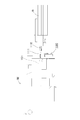
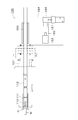
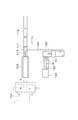
- the top view of the automatic processing system provided with the material supply apparatus of this invention. The top view of the initial position of the material supply apparatus of this invention.
- FIG. 1 and 2 show a processing system including a material supply apparatus 100 according to an embodiment of the present invention.
- the processing system is configured by disposing the material supply device 100 between an automatic lathe M and a bar feeder B.
- the automatic lathe M is a known automatic lathe, and has a hollow main shaft 101 that can be driven to rotate.
- a chuck H is provided at the front end of the main shaft 101, and the material gripped by the chuck H is processed by a processing tool. .
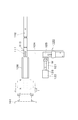
- the bar feeder B is a known bar feeder, which has a push bar 112 in which a long bar is accommodated in the main body and which is slidable in the axial direction of the main shaft 101 of the automatic lathe M.
- the automatic lathe M is arranged so that the pushing arrow 112 and the main shaft 101 are located on the same axis.
- a finger chuck 111 that holds the rear end of the bar is attached to the front end of the push arrow 112, and holding means for holding the material by the finger chuck 111 is configured.
- the push arrow 112 is a rear end of the main shaft 101. It is possible to move between a position separated from the rear main shaft 101 and the main shaft 101.
- the bar feeder B selects one bar and moves the pushing arrow 112 in the axial direction of the main shaft 101 in a state where the rear end of the bar is held by the finger chuck 111, thereby causing the rear end of the main shaft 101 to move.
- the bar is pushed into the main shaft 101 and supplied.
- the processing system inserts and supplies the bar material from the rear of the main shaft 101 into the main shaft 101 of the automatic lathe M by the bar feeder B, and automatically processes the bar material sequentially by the automatic lathe M. Can do.
- the material supply apparatus 100 includes a reciprocating table 124 provided so as to be able to advance and retreat in a horizontal direction perpendicular to the axis of the main shaft 101.
- a reciprocating table 124 On the reciprocating table 124, a material receiver 121 and a pusher 122 are provided.
- a finger pressing mechanism 125 and a guide member 126 are provided.
- the reciprocating table 124 is in a guide posture in which the guide member 126 is positioned between the pushing arrow 112 separated from the main shaft 101 and the rear end of the main shaft 101 and the supply posture in which the material receiver 121 is positioned by the forward and backward movement. Can be switched.
- the guide member 126 extends in the axial direction of the main shaft 101 so that the pushing arrow 112 can be guided integrally with the finger chuck 111 along the axial direction of the main shaft 101 when the reciprocating table 124 is guided. .
- the material receiver 121 accommodates a raw material that is a material formed in advance in a predetermined shape as a short material, and the raw material is positioned by being accommodated in the material receiver 121. It constitutes a positioning means for the raw material.
- the raw material is supplied to the material receiver 121 one by one by a conventionally known parts feeder or the like.
- the material receiver 121 can be configured by using vacuum suction, an openable / closable chuck, or the like in order to position the base material with high accuracy.
- the pusher 122 is composed of a cylinder disposed opposite to the material receiver 121. By pushing the piston rod 123 from the cylinder, the pusher 122 presses the shaped material in the material receiver 121 and pushes it out of the material receiver 121 to move the material.
- the material moving means is configured.
- the pusher 122 moves the material toward the finger chuck 111 by pushing out the shaped material from the material receiver 121 as described above when the reciprocating table 124 facing the finger chuck 111 is in the supply posture.
- the raw material can be inserted and supplied.
- a chuck that grips the material may be used as the material moving unit, and the chuck that grips the material and the finger chuck 111 may be relatively moved.
- the finger pressing mechanism 125 is disposed on the opposite side of the pusher 122 with the material receiver 121 interposed therebetween, and when the reciprocating table 124 is supplied, the finger chuck 111 is positioned by clamping or the like, and the raw material is held on the finger chuck 111. At this time, positioning means for positioning the finger chuck 111 is configured. However, the finger pressing mechanism 125 may fix the finger chuck 111 with another mechanism.
- the finger chuck 111 By positioning the finger chuck 111 with the finger pressing mechanism 125, the finger chuck 111 can be prevented from swinging due to the swing of the pushing arrow 112, and the pusher 122 can stably insert and supply the shaped material to the finger chuck 111. Can do.
- the pusher 122, the material receiver 121, and the finger pressing mechanism 125 constitute a material supply unit 120 that individually supplies the raw material to the finger chuck 111.
- the pusher 122, the material receiver 121, and the finger pressing mechanism 125 are retracted from the position opposed to the finger chuck 111 by setting the reciprocating table 124 to the guide posture, and the guide member 126 is moved.
- the pushing arrow 112 is moved along the axial direction of the main shaft 101 while being guided integrally with the finger chuck 111 by the guide member 126, and the shaped material is moved from the rear end of the main shaft 101 to the main shaft 101. It can be pushed in.
- the automatic lathe M can grip the shaped material supplied by being pushed into the main shaft 101 with the chuck H and process it with the tool.
- the push arrow 112 comes out of the main shaft 101 after being gripped by the chuck H of the main shaft 101, and is separated from the rear end of the main shaft 101.
- the pusher 122 is provided on the reciprocating table 124 integrally with the material receiver 121, and moves integrally with the reciprocating table 124 by the advance / retreat operation of the reciprocating table 124, and presses the material when the reciprocating table 124 is supplied.
- the pusher 122 is located at a working position for moving with respect to the finger chuck 111 and is located at a retreating position that allows supply of the shaped material to the main shaft 101 by the push arrow 112 when the reciprocating table 124 is in the guiding posture.
- the pushing means 112 of the bar feeder B and the finger chuck 111 push the raw material into the main shaft 101 from the rear end to supply the raw material, and the raw material pushing means of the material supply device 100
- the holding means provided at the tip of the material pushing means is also used so as to hold.
- the pusher 122 moves both the bar and the shaped material to the spindle 101 by moving to the retracted position by changing the posture of the reciprocating table 124 to the guide posture, except when supplying the shaped material to the finger chuck 111. It does not interfere with the push-in insertion work.
- the guide member 126 guides the pushing arrow 112 integrally with the finger chuck 111 and supplies the rod to the spindle 101 without hindering the supply of the rod to the spindle 101. Is stably performed by guiding the pushing arrow 112 (including the finger chuck 111) by the guide member 126, and the operation of pushing and inserting the bar and the shaped material into the main shaft 101 can be performed smoothly. The material can also be guided by the guide member 126.
- the processing system uses the reciprocating table 124 as a guide posture to supply a bar to the main shaft 101 by the bar feeder B, and uses the bar feeder B as it is, while changing the posture of the reciprocating table 124 as described above, It is possible to supply the shaped material to the main shaft 101 by the push arrow 112 without changing the configuration.
- a processing system that does not require another loader such as a gantry loader and can process both a low-cost and space-saving bar material and a short material such as a shaped material.
- the chuck H of the spindle 101 can be a three-claw chuck or the like capable of gripping both a normal bar and a shaped material.
- the material supply device 100 is provided between the automatic lathe M and the bar feeder B, the interval between the automatic lathe M and the bar feeder B may be increased, but the guide member 126 of the material supply device 100 is provided. Since it is located on the axis, the long bar can be smoothly supplied to the main shaft 101.
- this material supply device 100 by adding this material supply device 100 to a conventional bar processing system composed of an automatic lathe and a bar feeder, the present processing stem can be easily obtained. Thereby, it is not necessary to prepare the processing system for the bar and the shaped material separately, and the material can be processed efficiently. Moreover, it can also be set as the material supply system which can supply both a bar and a raw material by adding this material supply apparatus 100 with respect to the conventional bar feeder.
- the finger chuck 111 replaces the one into which the base material is inserted and the one that holds the bar material and attaches it to the pushing arrow 112, and also makes the base material and the bar material common. You can also.
- the material receiver 121 may be exchangeable according to a shape material having a different shape and size.
- the driving force for projecting and retracting the piston rod 123 of the pusher 122 may be generated by any mechanism such as a mechanical type, an electromagnetic type, and a hydraulic type.
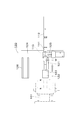
- the reciprocating table 124 has a supply posture position where the material receiver 121 is positioned between the pushing arrow 112 separated from the main shaft 101 and the rear end of the main shaft 101 (working position of the material moving means).
- the finger chuck 111 is retracted to a position where the material W supplied to the material receiver 121 can be received.
- the piston rod 123 of the pusher 122 is also retracted to the main shaft side of the short material W such as the shaped material supplied to the material receiver 121.
- the reciprocating table 124 is in a guide posture position where the guide member 126 is positioned between the pushing arrow 112 separated from the main shaft 101 and the rear end of the main shaft 101 (the retracted position of the material moving means). ) And the material receiver 121 faces the finger chuck 111. At this time, the finger presser mechanism 125 is operated and the finger chuck 111 is positioned and fixed.
- the piston rod 123 of the pusher 122 protrudes, and the material W is pushed out toward the finger chuck 111 and held by the finger chuck 111.
- the finger chuck 111 is provided with a slit 113 from the front end side, and the material W is elastically held by being inserted into the front end portion of the finger chuck 111. You may hold
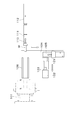
- the reciprocating table 124 moves to the position in the supply posture described above (the working position of the material moving means), and the guide member 126 faces the finger chuck 111 holding the material W.
- the piston rod 123 of the pusher 122 is also retracted so that the next material W can be supplied to the material receiver 121.
- the material W is held by the finger chuck 111, passes through the guide member 126, and is pushed to the front end of the main shaft 101.
- the finger chuck 111 completes the supply of the material W and returns to a position where the material W supplied to the material receiver 121 can be received.
- the next material W is supplied to the material receiver 121, and a series of operations are repeated again so that a large number of materials W are continuously supplied to the chuck H at the front end of the spindle 101.
- the finger chuck 111 is pushed out and held by the finger chuck 111, the finger chuck 111 moves backward, the reciprocating table 124 moves to the position in the guide posture (the retracted position of the material moving means), and the guide chuck 126 holds the material W.
- the operation up to the point can be performed in parallel while the material W supplied immediately before is gripped by the chuck H at the front end of the spindle 101 and processed, so the handling time not involved in processing is reduced.
- the processing time per material as a whole can be shortened.
- replenishment of the material to the material receiver 121 can be performed when the material is held by the finger chuck 111 and the reciprocating table 124 is switched to the supply posture, and the supply of the material W to the finger chuck 111 can be performed smoothly and shortly. Can be done in time.
- the push arrow 112 is inserted into the main shaft 101 and the next material to be processed is put on standby in the main shaft 101. You can also. When waiting for the material to be processed next in the main shaft 101, it is desirable to place the material immediately after the chuck H.
- the push arrow 112 is passed through the main shaft 101 and the material W is directly gripped by the chuck of the rear main shaft 102 and supplied. Can do.
- the material W can be gripped by the inner diameter chuck and processed on the rear main shaft 102.
- the timing of retracting the piston rod 123 of the pusher 122 and supplying the next material W to the material receiver 121 is not limited to the above, and may be performed at an appropriate timing in a series of operations.
- the material supply apparatus 100 of the present invention is applied to the automatic lathe M.
- any processing can be used as long as the material is pushed and supplied from the rear end to the hollow main shaft having the chuck at the front end. You may use for a machine, an assembly apparatus, and a processing apparatus.
Landscapes
- Engineering & Computer Science (AREA)
- Mechanical Engineering (AREA)
- Turning (AREA)
- Feeding Of Workpieces (AREA)
- Automatic Assembly (AREA)
Priority Applications (5)
| Application Number | Priority Date | Filing Date | Title |
|---|---|---|---|
| EP10820354.8A EP2484466B1 (en) | 2009-10-01 | 2010-09-14 | Stock feeding apparatus |
| KR1020127009671A KR101698019B1 (ko) | 2009-10-01 | 2010-09-14 | 재료 공급 장치 및 가공 시스템 |
| CN201080043318.8A CN102665974B (zh) | 2009-10-01 | 2010-09-14 | 材料供给装置以及加工系统 |
| ES10820354T ES2832500T3 (es) | 2009-10-01 | 2010-09-14 | Dispositivo de suministro de material |
| US13/499,692 US8726770B2 (en) | 2009-10-01 | 2010-09-14 | Machine tool |
Applications Claiming Priority (2)
| Application Number | Priority Date | Filing Date | Title |
|---|---|---|---|
| JP2009229280A JP5457126B2 (ja) | 2009-10-01 | 2009-10-01 | 材料供給装置および加工システム |
| JP2009-229280 | 2009-10-01 |
Publications (1)
| Publication Number | Publication Date |
|---|---|
| WO2011040235A1 true WO2011040235A1 (ja) | 2011-04-07 |
Family
ID=43826061
Family Applications (1)
| Application Number | Title | Priority Date | Filing Date |
|---|---|---|---|
| PCT/JP2010/065844 WO2011040235A1 (ja) | 2009-10-01 | 2010-09-14 | 材料供給装置 |
Country Status (8)
| Country | Link |
|---|---|
| US (1) | US8726770B2 (zh) |
| EP (1) | EP2484466B1 (zh) |
| JP (1) | JP5457126B2 (zh) |
| KR (1) | KR101698019B1 (zh) |
| CN (1) | CN102665974B (zh) |
| ES (1) | ES2832500T3 (zh) |
| TW (1) | TWI508800B (zh) |
| WO (1) | WO2011040235A1 (zh) |
Cited By (1)
| Publication number | Priority date | Publication date | Assignee | Title |
|---|---|---|---|---|
| US9731353B2 (en) | 2013-09-18 | 2017-08-15 | Citizen Machinery Co., Ltd. | Bar material supplying device and numerical control machine tool having the same |
Families Citing this family (7)
| Publication number | Priority date | Publication date | Assignee | Title |
|---|---|---|---|---|
| WO2014064847A1 (ja) * | 2012-10-26 | 2014-05-01 | 育良精機株式会社 | 棒材供給機及び送り矢セット |
| ITUB20155834A1 (it) * | 2015-11-24 | 2017-05-24 | Cucchi Giovanni & C Srl | Dispositivo e metodo per recuperare e scaricare spezzoni di barre da una macchina utensile |
| JP6807192B2 (ja) * | 2016-08-31 | 2021-01-06 | シチズン時計株式会社 | 工作機械 |
| CN112238226B (zh) * | 2020-10-24 | 2021-08-20 | 上海万众实业股份有限公司 | 一种行星齿轮数控车床出料装置 |
| JP7108148B1 (ja) * | 2021-04-30 | 2022-07-27 | Dmg森精機株式会社 | バーフィーダ及び工作機械 |
| CN113319304A (zh) * | 2021-06-07 | 2021-08-31 | 辽阳奥鹏汽车零部件有限公司 | 一种生产变直径圆棒材料的装置及加工方法 |
| CN113927352A (zh) * | 2021-10-18 | 2022-01-14 | 安徽信息工程学院 | 一种棒材生产线送料装置 |
Citations (7)
| Publication number | Priority date | Publication date | Assignee | Title |
|---|---|---|---|---|
| JPS5376283U (zh) * | 1976-11-29 | 1978-06-26 | ||
| JPS5917101U (ja) * | 1982-07-26 | 1984-02-02 | 日本特殊陶業株式会社 | 円筒物のチヤツク插入時の案内受具 |
| JPS59156705A (ja) | 1983-02-25 | 1984-09-06 | 松下電工株式会社 | 軽量厚物硬化体の製法 |
| JPS627301A (ja) | 1985-06-29 | 1987-01-14 | Toshiba Corp | 浮上式搬送装置 |
| JPH07328803A (ja) * | 1994-06-02 | 1995-12-19 | Nakamura Tome Precision Ind Co Ltd | 旋盤の材料押込装置 |
| JP2007118163A (ja) * | 2005-10-31 | 2007-05-17 | Star Micronics Co Ltd | 旋盤 |
| JP3134196U (ja) * | 2007-05-09 | 2007-08-09 | 三重精機株式会社 | 旋盤加工機、および、ローディング装置 |
Family Cites Families (15)
| Publication number | Priority date | Publication date | Assignee | Title |
|---|---|---|---|---|
| US2833545A (en) * | 1957-03-01 | 1958-05-06 | Balas Collet Mfg Company | Pusher device having adjustable tension |
| GB1288385A (zh) * | 1969-02-07 | 1972-09-06 | ||
| DE2537852C3 (de) * | 1975-08-26 | 1978-03-16 | Hagenuk Vormals Neufeldt & Kuhnke Gmbh, 2300 Kiel | Automatische Zuführvorrichtung für Profilstangen an stangenverarbeitenden Drehmaschinen |
| JPS5376283A (en) | 1976-12-18 | 1978-07-06 | Mitsubishi Electric Corp | Stopping control of moving body |
| JPS5917101A (ja) | 1982-07-21 | 1984-01-28 | Toshiba Corp | 回転角度検出装置 |
| JPS59156705U (ja) * | 1983-11-16 | 1984-10-20 | アヅマ産業株式会社 | 自動加工機の制御装置 |
| JPH03134196A (ja) * | 1989-10-18 | 1991-06-07 | Mitsui High Tec Inc | リードフレームのめっき装置 |
| US5347896A (en) * | 1992-12-21 | 1994-09-20 | Bausch & Lomb Incorporated | Automated collet loading for the manufacture of contact lenses |
| US5505584A (en) * | 1994-07-21 | 1996-04-09 | J. F. Berns Company, Inc. | Air operated loading and unloading device |
| JP3641304B2 (ja) * | 1995-09-07 | 2005-04-20 | 株式会社アルプスツール | フィンガーチャック |
| JP3134196B1 (ja) * | 1999-09-22 | 2001-02-13 | 工業技術院長 | 二重整列ペロブスカイト構造磁気抵抗素子とその使用方法 |
| JP3723465B2 (ja) * | 2001-04-20 | 2005-12-07 | 株式会社育良精機製作所 | 棒材供給方法および棒材供給機 |
| CN100506442C (zh) * | 2003-11-28 | 2009-07-01 | 西铁城控股株式会社 | 数控自动车床的棒材供给装置 |
| EP1637256B1 (en) * | 2004-09-15 | 2014-04-02 | PIETRO CUCCHI S.p.A. | Automatic bar-loader provided with linear sensors of the position of the bar-pusher and automatic lathe including said loader |
| CN201168788Y (zh) * | 2008-03-31 | 2008-12-24 | 何森权 | 车床棒料自动送进装置的导料装置 |
-
2009
- 2009-10-01 JP JP2009229280A patent/JP5457126B2/ja not_active Expired - Fee Related
-
2010
- 2010-09-14 WO PCT/JP2010/065844 patent/WO2011040235A1/ja active Application Filing
- 2010-09-14 KR KR1020127009671A patent/KR101698019B1/ko active IP Right Grant
- 2010-09-14 ES ES10820354T patent/ES2832500T3/es active Active
- 2010-09-14 CN CN201080043318.8A patent/CN102665974B/zh active Active
- 2010-09-14 EP EP10820354.8A patent/EP2484466B1/en active Active
- 2010-09-14 US US13/499,692 patent/US8726770B2/en active Active
- 2010-09-29 TW TW099132990A patent/TWI508800B/zh active
Patent Citations (7)
| Publication number | Priority date | Publication date | Assignee | Title |
|---|---|---|---|---|
| JPS5376283U (zh) * | 1976-11-29 | 1978-06-26 | ||
| JPS5917101U (ja) * | 1982-07-26 | 1984-02-02 | 日本特殊陶業株式会社 | 円筒物のチヤツク插入時の案内受具 |
| JPS59156705A (ja) | 1983-02-25 | 1984-09-06 | 松下電工株式会社 | 軽量厚物硬化体の製法 |
| JPS627301A (ja) | 1985-06-29 | 1987-01-14 | Toshiba Corp | 浮上式搬送装置 |
| JPH07328803A (ja) * | 1994-06-02 | 1995-12-19 | Nakamura Tome Precision Ind Co Ltd | 旋盤の材料押込装置 |
| JP2007118163A (ja) * | 2005-10-31 | 2007-05-17 | Star Micronics Co Ltd | 旋盤 |
| JP3134196U (ja) * | 2007-05-09 | 2007-08-09 | 三重精機株式会社 | 旋盤加工機、および、ローディング装置 |
Cited By (1)
| Publication number | Priority date | Publication date | Assignee | Title |
|---|---|---|---|---|
| US9731353B2 (en) | 2013-09-18 | 2017-08-15 | Citizen Machinery Co., Ltd. | Bar material supplying device and numerical control machine tool having the same |
Also Published As
| Publication number | Publication date |
|---|---|
| EP2484466A1 (en) | 2012-08-08 |
| EP2484466A4 (en) | 2017-01-25 |
| KR101698019B1 (ko) | 2017-01-20 |
| CN102665974A (zh) | 2012-09-12 |
| TW201113111A (en) | 2011-04-16 |
| TWI508800B (zh) | 2015-11-21 |
| US8726770B2 (en) | 2014-05-20 |
| EP2484466B1 (en) | 2020-11-04 |
| CN102665974B (zh) | 2015-03-04 |
| KR20120093883A (ko) | 2012-08-23 |
| JP2011073117A (ja) | 2011-04-14 |
| ES2832500T3 (es) | 2021-06-10 |
| JP5457126B2 (ja) | 2014-04-02 |
| US20120186407A1 (en) | 2012-07-26 |
Similar Documents
| Publication | Publication Date | Title |
|---|---|---|
| WO2011040235A1 (ja) | 材料供給装置 | |
| JP2011073117A5 (zh) | ||
| JP2009113139A (ja) | 工作機械 | |
| JPH079214A (ja) | 改良型工具保持装置 | |
| TW201200271A (en) | Machine tool | |
| JP5575063B2 (ja) | ワーク保持装置交換支持装置 | |
| KR101059946B1 (ko) | 푸시-풀형 환봉 소재 공급장치 | |
| KR102004051B1 (ko) | 너트 태핑 장치 | |
| JP3723465B2 (ja) | 棒材供給方法および棒材供給機 | |
| JP6840082B2 (ja) | 材料案内装置および材料案内装置を備えた工作機械 | |
| JP3134196U (ja) | 旋盤加工機、および、ローディング装置 | |
| CN104259511A (zh) | 一种带定位孔棒材的全自动加工装置及其方法 | |
| KR102632289B1 (ko) | 공작기계 및 가공방법 | |
| US3266348A (en) | Bar feeding device | |
| CN103028988A (zh) | 一种背面主轴自动排料装置 | |
| JP2005059117A (ja) | 棒材供給機 | |
| JPH10216876A (ja) | ダイス移動式インライン間欠伸線機 | |
| KR100734564B1 (ko) | 선반의 척킹 보조장치 및 척킹방법 | |
| JPS5925571Y2 (ja) | 管材の曲げ装置 | |
| JP4984258B2 (ja) | 棒材加工システム | |
| CN202621931U (zh) | 一种背面主轴自动排料装置 | |
| JPS61182704A (ja) | 両端加工機の棒材ロ−デイング方法 | |
| JP5998417B2 (ja) | 棒材供給機 | |
| CN112222308A (zh) | 穿芯定位装置及管件自动冲压设备 | |
| JP2009078355A (ja) | ワーク供給装置 |
Legal Events
| Date | Code | Title | Description |
|---|---|---|---|
| WWE | Wipo information: entry into national phase |
Ref document number: 201080043318.8 Country of ref document: CN |
|
| 121 | Ep: the epo has been informed by wipo that ep was designated in this application |
Ref document number: 10820354 Country of ref document: EP Kind code of ref document: A1 |
|
| WWE | Wipo information: entry into national phase |
Ref document number: 2010820354 Country of ref document: EP |
|
| NENP | Non-entry into the national phase |
Ref country code: DE |
|
| WWE | Wipo information: entry into national phase |
Ref document number: 13499692 Country of ref document: US |
|
| ENP | Entry into the national phase |
Ref document number: 20127009671 Country of ref document: KR Kind code of ref document: A |