EP2474444B1 - Rail de sécurisation de charge - Google Patents
Rail de sécurisation de charge Download PDFInfo
- Publication number
- EP2474444B1 EP2474444B1 EP11010064.1A EP11010064A EP2474444B1 EP 2474444 B1 EP2474444 B1 EP 2474444B1 EP 11010064 A EP11010064 A EP 11010064A EP 2474444 B1 EP2474444 B1 EP 2474444B1
- Authority
- EP
- European Patent Office
- Prior art keywords
- load securing
- securing rail
- anchorage
- accordance
- rail
- Prior art date
- Legal status (The legal status is an assumption and is not a legal conclusion. Google has not performed a legal analysis and makes no representation as to the accuracy of the status listed.)
- Not-in-force
Links
Images


Classifications
-
- B—PERFORMING OPERATIONS; TRANSPORTING
- B60—VEHICLES IN GENERAL
- B60P—VEHICLES ADAPTED FOR LOAD TRANSPORTATION OR TO TRANSPORT, TO CARRY, OR TO COMPRISE SPECIAL LOADS OR OBJECTS
- B60P7/00—Securing or covering of load on vehicles
- B60P7/06—Securing of load
- B60P7/08—Securing to the vehicle floor or sides
- B60P7/0807—Attachment points
- B60P7/0815—Attachment rails or trellis
Definitions
- the invention relates to a load securing rail for attachment to a wall or ceiling of a cargo space of a transport vehicle or container, which comprises an anchoring means receiving a first type, which defines a first anchoring line extending in the longitudinal direction of the load securing rail.
- Load securing rails of this type are basically known and are also referred to as anchor or Zurrschienen. They serve to secure cargo in commercial vehicle bodies or containers, by allowing the anchoring of cargo securing elements, such as lashing straps or locking bars. Usually, conventional load securing rails are each designed for a particular anchoring system.
- conventional load securing rails are made of stainless steel or galvanized sheet steel. Especially the latter material proves to be problematic insofar as the use of galvanized parts according to applicable hygiene regulations for the transport of food is undesirable.
- galvanized load securing rails are prone to corrosion by the use of chemical cleaning agents and damage. Accordingly, the cleaning of steel rails causes problems, especially can be hard to reach places of the rails, so-called blind spots, breeding grounds of bacteria and small animals.
- conventional steel rails are only available in a certain length, so that an extension of the load securing rail over the entire length of a commercial vehicle body or container under certain circumstances, a plurality of rail parts must be joined together.
- galvanized steel rails if they are to be flush with a side wall of a cargo space, need additional recesses in the side wall at the top and bottom, in which they are glued and additionally riveted. In this case, galvanized steel rails must be pretreated for the gluing process.
- Load securing rails with several mutually parallel anchoring lines are from the US 2004/0028497 A1 and the DE 20 2009 011 410 U1 known. In both cases, however, the anchoring lines are defined only by a plurality of mutually spaced anchoring windows.
- the US 2009/0003958 A1 discloses a load securing rail having an approximately double U-shaped cross-section, along the center line of which a series of detent openings is additionally arranged. Further load securing rails are from the DE 94 09 059 U1 . WO 01/15933 A1 . DE 86 17 373 U1 . DE 10 2008 058 006 B3 and US 7556463 B1 known.
- the invention has for its object to provide a load securing rail, which is versatile.
- a load securing rail is provided with the features of claim 1.
- the load securing rail is prepared for the use of at least three different anchoring systems, so that the load securing rail can be used more versatile and a more individual securing of cargo is possible. It is therefore not limited to the selection and installation of the load securing rail on a particular anchoring system, but can fall back on different anchoring systems as needed.
- the anchoring lines extend in the longitudinal direction of the load securing rail and the anchoring means receptacles extend over the entire length of the load securing rail in particular, depending on the specific design of the anchoring means receptacles or the anchoring means to be anchored, it is basically possible to fix the anchoring means at any longitudinal position of the load securing rail , which increases the flexibility in securing cargo.
- the various anchoring device mounts are particularly suitable for anchoring lashing belt locks, loading or locking beams or locking bars.
- the order of arrangement of the various anchoring means shots is basically arbitrary. That is, the T-shaped anchoring groove does not necessarily have to be located between the double V-shaped anchoring groove and the anchoring windows. It is also possible to provide the double V-shaped anchoring groove between the T-shaped anchoring groove and the anchoring windows or to arrange the anchoring windows between the double V-shaped anchoring groove and the T-shaped anchoring groove.
- the anchoring means receptacles are provided with drain openings through which liquid can drain from the anchoring means receptacles.
- at least one drain opening may be provided in a lower one of the front wall sections of the double V-shaped and / or T-shaped anchoring groove and / or on an underside of at least one anchoring window.
- the drainage holes allow drainage of dirty water from the load securing rail after cleaning the same by means of, for example, a high-pressure steam cleaner.
- the load securing rail can be easily and reliably kept clean in this way, in particular, the accumulation of bacteria and small animals is effectively prevented.
- the load securing rail thus facilitates compliance with hygiene requirements, as they apply, for example, for the transport of food.
- a drain opening of an anchoring groove simultaneously forms part of a notch for inserting an anchoring means into the anchoring groove.
- the drainage opening fulfills a double function, on the one hand serving as an insertion opening for the insertion of an anchoring means and at the same time allowing drainage of dirty water.
- An additional immersion opening or notch does not need to be provided in this case.
- the load securing rail is preferred by an extruded profile, in particular made of aluminum anodized aluminum, formed. Because of this material, the load securing rail is not only suitable for foodstuffs, but can be produced as an extruded profile in basically any length in one piece. In this way, it is possible to equip a commercial vehicle body or container over its entire length with a one-piece load securing rail, which at the same time simplifies installation contributes to increased stability and thus ultimately ensures increased cargo security.
- the load securing rail seen in cross section on a substantially trapezoidal outline whose longer base side forms the front of the load securing rail, i. that is, the side over which the anchoring means receptacles are accessible.
- the trapezoidal outline of the load securing rail allows a more reliable mounting of the load securing rail in the wall of a commercial vehicle body or container and in particular an optimized transmission of the forces exerted on the load securing rail by load securing elements anchored in the load securing rail to the wall.
- the trapezoidal outline of the load securing rail thus contributes to a more reliable load securing.
- the load securing rail can, for example, be glued into a recess adapted to the trapezoidal contour of the load securing rail in the wall of a commercial vehicle body or container.
- at least one rib extending in the longitudinal direction of the load securing rail is advantageously formed on a rear side of the load securing rail.
- a projection extending in the longitudinal direction of the load securing rail can be formed in areas of oblique sides of the load securing rail adjoining the front side.
- the projections or rib prevent the back and oblique sides of the load securing rail from abutting flat against the wall surface delimiting the well and thus effectively acting as spacers defining large gap areas between the load securing rail and the wall in which glue collects and a ensure large-area and reliable adhesion of the load securing rail in the wall.
- the load securing rail forms a wall of a substantially rectangular profile frame.
- the load securing rail can be mounted in the edge region of a load compartment floor, for example as a so-called beverage mat, in order to prevent cargo, e.g. Beverage crates, can slip sideways out of the hold.
- a support strut between the load securing rail and an opposite wall of the profile frame is formed.
- latching projection is preferably formed on an underside of the profile frame, which allows easy insertion of the profile frame in a correspondingly provided on the load compartment floor latching opening.
- the latching projection preferably extends over the entire length of the profile frame and can either be continuous or divided into elongated sections.
- the latching projection may, for example, have a cross-shaped cross-sectional profile.
- a, in particular adapted to the latching projection, locking groove is formed on an upper side of the profile frame.
- the latching projection and the latching groove are preferably formed in such a form that the latching projection in the immersed in the latching state under load of the load securing rail by loading undergoes a lock in the locking groove, so that the mated profile frame are securely connected to each other even under load.
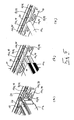
- a load securing rail 10 according to a first embodiment is shown, which is integrated into the side wall 12 of a commercial vehicle body or container and extends in the longitudinal direction of the commercial vehicle body or container preferably over its entire length.
- the load securing rail 10 as in Fig. 1 to 5 shown, vertically oriented.
- top and “bottom” used below refer to the vertical orientation of the load securing rail 10 shown in the figures.
- the load securing rail 10 is an extruded profile of anodized aluminum, which is basically produced in any length. It goes without saying that the load securing rail 10 may also be composed of several sections can be, as it is in the middle section of Fig. 4 is shown.
- the load securing rail 10 allows the anchoring of different load securing elements, such as a loading beam 14a (FIG. Fig. 5a ), a barrier bar 14b ( Fig. 5b ), a locking bar 14c ( Fig. 5c ) or a lashing strap, not shown.
- a loading beam 14a (FIG. Fig. 5a )
- a barrier bar 14b ( Fig. 5b )
- a locking bar 14c Fig. 5c
- lashing strap not shown.
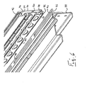
- the load securing rail 10 on its front side on three different anchoring means receptacles 16 which define three mutually parallel and extending in the longitudinal direction of the load securing rail 10 anchoring lines.
- a first anchoring means receptacle 16a is formed by a double V-shaped cross-section anchoring groove 18 defined by a W-shaped rear wall portion 20 and two front wall portions 22 forming adjoining and undercuts. Between the front wall sections 22, the rear wall section 20 is formed into a central web 24, the front side of which terminates substantially flush with the front sides of the front wall sections 22.
- latching recesses 26 in the present embodiment, locking grooves distributed, which allow the latching of anchoring means of the load securing elements 14, for example, an anchor shoe 28 of the loading beam 14a (FIG. Fig. 5a ) or a buckle of a lashing strap.
- an anchor shoe 28 of the loading beam 14a FIG. Fig. 5a
- a buckle of a lashing strap By locking a load securing element 14 in the anchoring groove 18 is a correct Positioning of the load securing element 14 in the anchoring groove 18 not only relieved, but also permanently ensured.
- a second anchoring means receptacle 16b in the form of a substantially T-shaped anchoring groove 30 which is defined at its front by two spaced apart front wall sections 32.
- the upper of the front wall portions 32 of the T-shaped anchoring groove 30 passes into the lower of the front wall portions 22 of the double-V-shaped anchoring groove 18.
- the T-shaped anchoring groove 30 is bounded by a substantially plane rear wall 34 of the load securing rail 10. Upwards, i. Thus, the double-V-shaped anchoring groove 18, the T-shaped anchoring groove 30 is bounded by a portion 36 of the W-shaped rear wall portion 20. Downwardly, the T-shaped anchoring groove 30 is bounded by a support wall 38 extending between the front wall section 32 and the rear rear wall 34.
- the notches 40 are formed substantially circular, ie in both the upper and in the lower of the front wall portions 32 of the T-shaped anchoring groove 30 corresponding part-circular recesses 42 are formed.
- a third anchoring means receptacle 16c which comprises a multiplicity of anchoring windows 44 distributed in the longitudinal direction of the load securing rail 10, each having a substantially rectangular shape.
- the anchoring windows 44 are cut in a front wall portion 46 of the load securing rail 10, which merges into the lower of the T-shaped anchoring groove 30 bounding front wall portions 32.
- the anchoring windows 44 provide access to a hollow chamber 48 of the load securing rail 10 which is defined by the front wall section 46, the support wall 38, the rear wall 34 and a lower sloping outer wall 50 which connects the rear wall 34 to the front wall section 46.
- each of the anchoring means receptacles 16 is provided with drainage openings 52.
- the drainage holes 52 of the double V-shaped anchoring groove 18 have the shape of notches 53 which are cut from above into the lower of the front wall portions 22 and extend to the lower portion 36 of the W-shaped rear wall portion 20 in the front wall portion 22 ,
- the drainage openings 52 of the T-shaped anchoring groove 30 are formed by the notches 40, more precisely by the recesses 42 formed in the lower of the front wall sections 32.
- the notches 40 thus perform a dual function in this case, by not only immersing an anchoring means allow in the T-shaped anchoring groove 30, but also the drainage of water from the same.
- the recesses 42 in the lower of the front wall sections 32 have to be formed so deep for this purpose that they reach as far as the support wall 38.
- the support wall 38 is also inclined slightly downwardly toward the front of the load securing rail 10, similarly as the lower section 36 of the W-shaped rear wall section 20 of the double V-type. shaped anchoring groove 18th
- the drainage openings 52 of the anchoring windows 44 are formed by cutouts 54 at the lower edge of the anchoring windows 44. According to the above-described drainage openings 52, these cutouts 54 also extend downwards so far that they reach as far as the inclined outer wall 50. As Fig. 1 and 2 show, the inclined outer wall 50 has an inclination such that no water can collect in the hollow chamber 48, but instead exits via the cutouts 52 serving as recesses 54 of the anchoring window 44.
- An oblique outer wall 55 corresponding to the lower oblique outer wall 50 is also provided on the upper side of the load securing rail 10.
- This upper sloping outer wall 55 connects the rear wall 34 of the load securing rail 10 with the upper front wall portion 22 of the double V-shaped anchoring groove 18.
- the upper inclined outer wall 55 has an upper portion of the W-shaped rear wall portion 20 of the double V-shaped anchoring groove 18.
- the front side essentially flush with each other front wall sections 22, 32, 46 give the load securing rail together with the substantially planar rear wall 34 and the oblique outer walls 50, 55 a substantially trapezoidal outline.
- the side wall 12 of the vehicle body or container is provided with a mounting recess 56 for receiving the load securing rail 10, which also has a trapezoidal cross section, which is adapted to the contour of the load securing rail 10, that the front of the load securing rail 10 in the installed state is substantially flush with the front of the side wall 12 closes.
- the spacer protrusions 62 which resemble the ribs 58, also project outward from the outer front wall sections 22, 46, so that Similar gap regions 64 for adhesive also along the oblique outer walls 50, 55 and adjoining areas of the planar rear wall 34 extend.
- a load securing rail according to a second embodiment is shown.
- the load securing rail 10 according to the second embodiment is formed substantially identical to the load securing rail 10 according to the first embodiment and differs from it ultimately only in that it is integrated into a substantially rectangular frame profile 70, in such a way that the load securing rail 10 a front side wall 72 of the frame profile forms.
- the frame profile 70 comprises a rear wall 74, which is connected via an upper wall 76 and a lower wall 78 with the load securing rail 10.
- To increase the stability of the frame profile 70 also extends a support strut 80 between the rear wall 74 and the rear wall 34 of the load securing rail 10th
- a plurality of elongated locking projections 82 are formed, which are distributed over the length of the frame profile 70.
- a latching projection extending continuously over the entire length of the frame profile 70.
- the locking projections 82 each have a cross-shaped cross-section, but other suitable cross-sections are conceivable.
- the load securing rail 10 can be mounted in a simple manner on a load compartment floor and used, for example, as a so-called beverage mat.
- a mounting bracket 86 may be attached to an end profile 88 of the load compartment floor ( Fig. 6 ), which is provided with elongated latching openings 90, in which the latching projections 82 of the frame profile 70 can be inserted and latched.
- the frame profile 70 On its upper wall 76, the frame profile 70 has an over the length of the frame profile 70 extending locking groove 92 which is adapted to the locking projections 82, so that a second load securing rail 10 of the same kind plugged or more load securing rails 10 can be assembled and locked together as it is in FIGS. 7 and 8 is shown.
- the cross-shaped detent projection 82 of the frame profile 70 is displaced laterally in the detent opening 90 of the mounting bracket 86 or in the detent groove 92 of a lower frame profile 70 this locked, that a lifting of the frame profile 70 is no longer possible.
Claims (12)
- Rail de sécurisation de charge (10) destiné au montage sur une paroi (12) ou un plafond d'un volume de chargement d'un véhicule de transport ou d'un réceptacle de transport, comprenant un récepteur pour organe d'ancrage (16) d'un premier type, qui comporte une rainure d'ancrage (18) avec une section transversale en forme de V double et qui définit une première ligne d'ancrage s'étendant en direction longitudinale du rail de sécurisation de charge (10),
un récepteur pour organe d'ancrage (16) d'un second type, différent du premier type, dans lequel le récepteur pour organe d'ancrage (16) du second type comporte une rainure d'ancrage (30) essentiellement en forme de T, qui est définie sur son côté antérieur par deux tronçons de paroi antérieure (32) écartés l'un de l'autre et qui définit une seconde ligne d'ancrage s'étendant essentiellement parallèlement à la première ligne d'ancrage, et
un récepteur pour organe d'ancrage (16) d'un troisième type, différent du premier et du second type, dans lequel le récepteur pour organe d'ancrage (16) du troisième type comporte une pluralité de fenêtres d'ancrage (44) écartées les unes des autres et définit une troisième ligne d'ancrage qui s'étend essentiellement parallèlement à la première et à la seconde ligne d'ancrage. - Rail de sécurisation de charge (10) selon la revendication 1,
caractérisé en ce que les récepteurs pour organe d'ancrage (16) sont dotés d'ouvertures d'écoulement (52) à travers lesquelles un liquide peut s'écouler hors des récepteurs pour organe d'ancrage (16). - Rail de sécurisation de charge (10) selon l'une des revendications précédentes,
caractérisé en ce qu'une ouverture d'écoulement (52) d'une gorge d'ancrage (30) forme une partie d'un évidement (40) pour mettre en place un organe d'ancrage dans la rainure d'ancrage (30). - Rail de sécurisation de charge (10) selon l'une des revendications précédentes,
caractérisé en ce qu'il est formé par un profilé extrudé, en particulier en aluminium, de préférence en aluminium anodisé. - Rail de sécurisation de charge (10) selon l'une des revendications précédentes,
caractérisé en ce qu'il présente en section transversale un contour essentiellement en forme de trapèze, dont la grande base forme un accès vers le côté antérieur du rail de sécurisation de charge (10) qui comporte les récepteurs pour organe d'ancrage (16). - Rail de sécurisation de charge (10) selon la revendication 5,
caractérisé en ce qu'au moins une nervure (58) s'étendant en direction longitudinale du rail de sécurisation de charge (10) est réalisée sur un côté postérieur du rail de sécurisation de charge ; et/ou une saillie (62) s'étendant en direction longitudinale du rail de sécurisation de charge (10) est respectivement réalisée dans des régions, adjacente au côté antérieur, de côtés en biseau du rail de sécurisation de charge (10). - Rail de sécurisation de charge (10) selon l'une des revendications précédentes,
caractérisé en ce qu'il forme une paroi d'un profilé de cadre (70) essentiellement rectangulaire. - Rail de sécurisation de charge (10) selon la revendication 7,
caractérisé en ce qu'au moins une saillie d'enclenchement (82), s'étendant en particulier en direction longitudinale, est réalisée sur un côté inférieur du profilé de cadre (70). - Rail de sécurisation de charge (10) selon la revendication 7 ou 8,
caractérisé en ce qu'une gorge d'enclenchement (92), s'étendant en direction longitudinale et en particulier adaptée à la saillie d'enclenchement (82), est réalisée sur un côté supérieur du profilé de cadre (70). - Rail de sécurisation de charge (10) selon la revendication 8 ou 9,
caractérisé en ce que la saillie d'enclenchement (82) est réalisée de telle manière, et présente en particulier un profil de section transversale en forme de croix, de telle façon qu'elle se verrouille automatiquement sous charge dans une gorge d'enclenchement (92) ou une ouverture d'enclenchement (90). - Rail de sécurisation de charge (10) selon l'une des revendications précédentes,
caractérisé en ce que la rainure d'ancrage (18) à section transversale en forme de V double est définie par un tronçon de paroi postérieur (20) en forme de W et par deux tronçons de paroi antérieurs (22) se raccordant à celui-ci et formant des contre-dépouilles. - Rail de sécurisation de charge (10) selon la revendication 11,
caractérisé en ce que le tronçon de paroi postérieur (20) est conformé entre les tronçons de paroi antérieurs (22) pour réaliser une barrette médiane (24) dont le côté antérieur se raccorde sensiblement en affleurement aux côtés antérieurs des tronçons de paroi antérieure (22).
Priority Applications (3)
| Application Number | Priority Date | Filing Date | Title |
|---|---|---|---|
| EP13153594.0A EP2591951B8 (fr) | 2011-01-11 | 2011-12-21 | Rail de sécurisation de charge |
| PL13153594T PL2591951T3 (pl) | 2011-01-11 | 2011-12-21 | Szyna zabezpieczająca ładunek |
| PL11010064T PL2474444T3 (pl) | 2011-01-11 | 2011-12-21 | Szyna zabezpieczająca ładunek |
Applications Claiming Priority (1)
| Application Number | Priority Date | Filing Date | Title |
|---|---|---|---|
| DE102011008254A DE102011008254A1 (de) | 2011-01-11 | 2011-01-11 | Ladungssicherungsschiene |
Related Child Applications (2)
| Application Number | Title | Priority Date | Filing Date |
|---|---|---|---|
| EP13153594.0A Division EP2591951B8 (fr) | 2011-01-11 | 2011-12-21 | Rail de sécurisation de charge |
| EP13153594.0A Division-Into EP2591951B8 (fr) | 2011-01-11 | 2011-12-21 | Rail de sécurisation de charge |
Publications (2)
| Publication Number | Publication Date |
|---|---|
| EP2474444A1 EP2474444A1 (fr) | 2012-07-11 |
| EP2474444B1 true EP2474444B1 (fr) | 2014-07-02 |
Family
ID=45470183
Family Applications (2)
| Application Number | Title | Priority Date | Filing Date |
|---|---|---|---|
| EP11010064.1A Not-in-force EP2474444B1 (fr) | 2011-01-11 | 2011-12-21 | Rail de sécurisation de charge |
| EP13153594.0A Not-in-force EP2591951B8 (fr) | 2011-01-11 | 2011-12-21 | Rail de sécurisation de charge |
Family Applications After (1)
| Application Number | Title | Priority Date | Filing Date |
|---|---|---|---|
| EP13153594.0A Not-in-force EP2591951B8 (fr) | 2011-01-11 | 2011-12-21 | Rail de sécurisation de charge |
Country Status (5)
| Country | Link |
|---|---|
| EP (2) | EP2474444B1 (fr) |
| CN (2) | CN102582502B (fr) |
| DE (1) | DE102011008254A1 (fr) |
| ES (2) | ES2508121T3 (fr) |
| PL (2) | PL2474444T3 (fr) |
Cited By (1)
| Publication number | Priority date | Publication date | Assignee | Title |
|---|---|---|---|---|
| DE102016109634B4 (de) | 2016-05-25 | 2020-07-30 | Schmitz Cargobull Aktiengesellschaft | Ladungssicherungshaken zum Verbinden eines Haltemittels mit einerLadungssicherungsschiene sowie Ladungssicherungsmittel und Aufbau einesNutzfahrzeugs jeweils mit dem Ladungssicherungshaken |
Families Citing this family (9)
| Publication number | Priority date | Publication date | Assignee | Title |
|---|---|---|---|---|
| WO2015127946A1 (fr) * | 2014-02-27 | 2015-09-03 | Wolfgang Rixen | Plaque de fixation |
| DE102015108731B4 (de) | 2015-06-02 | 2023-06-07 | Kiesling Fahrzeugbau Gmbh | Ladungssicherungssystem für einen Ladungsaufbau eines Nutzfahrzeugs |
| DE202015102860U1 (de) | 2015-06-02 | 2015-06-25 | Kiesling Fahrzeugbau Gmbh | Ladungssicherungssystem für einen Ladungsaufbau eines Nutzfahrzeugs |
| GB2550609A (en) * | 2016-05-25 | 2017-11-29 | Loadlok Mfg Limited | Restraint track |
| EP3248837B1 (fr) | 2016-05-25 | 2020-08-12 | Schmitz Cargobull AG | Caisson d'un vehicule utilitaire dote de rail de securisation de charge |
| DE102017206874A1 (de) * | 2017-04-24 | 2018-10-25 | Volkswagen Aktiengesellschaft | Verzurrschiene, Laderaumfläche, Fahrzeug |
| EP3590800A1 (fr) * | 2018-07-06 | 2020-01-08 | Schmitz Cargobull AG | Coffre pour un véhicule utilitaire à profilé de sécurité de charge |
| DE202021103984U1 (de) | 2021-07-27 | 2021-10-29 | CliXBond GmbH | Ankerschiene in einem LKW-Aufbau |
| DE102021128297A1 (de) * | 2021-10-29 | 2023-05-04 | Kögel Trailer GmbH | Haltevorrichtung, System, Aufbau und Verfahren |
Citations (3)
| Publication number | Priority date | Publication date | Assignee | Title |
|---|---|---|---|---|
| US20090003958A1 (en) * | 2007-06-27 | 2009-01-01 | Knox Howard Thomas | Anchor lock tether fitting |
| US7556463B1 (en) * | 2005-06-06 | 2009-07-07 | Hall Kennith C | Mounting structure |
| DE102008058006B3 (de) * | 2008-11-19 | 2010-08-26 | SORTIMO INTERNATIONAL AUSRÜSTUNGSSYSTEME FÜR SERVICEFAHRZEUGE GmbH | Gepäckbefestigungseinrichtung mit Verzurrmechanismus |
Family Cites Families (10)
| Publication number | Priority date | Publication date | Assignee | Title |
|---|---|---|---|---|
| DE8605022U1 (de) * | 1986-02-25 | 1986-06-19 | Gross Aluminium Gmbh, 6000 Frankfurt | Bordwandprofil mit Zurrschienenhalterung |
| DE8617373U1 (de) * | 1986-06-28 | 1986-10-23 | Mkg Metall- Und Kunststoffverarbeitungsgesellschaft Mbh, 4531 Lotte | Ankerschiene für Nutzfahrzeuge |
| DE9409059U1 (de) * | 1994-06-03 | 1994-08-11 | Wuellhorst Gmbh & Co Kg | Profilleiste für Laderaumböden von Transportfahrzeugen |
| FI106946B (fi) * | 1999-04-01 | 2001-05-15 | Finnlines Oyj | Menetelmä ja laite horisontaalisesti lastattavien lastiyksiköiden kiinnittämiseksi alukseen |
| US6250861B1 (en) * | 1999-08-27 | 2001-06-26 | Jerald M. Whitehead | Side rail for flatbed trailers and trucks |
| US6799927B2 (en) * | 2002-08-09 | 2004-10-05 | Donald G. Wheatley | Tie down anchor system |
| DE20214793U1 (de) * | 2002-09-25 | 2003-03-06 | Elze Waggonbau Gmbh & Co Kg | Längsrillenprofil |
| DE20218399U1 (de) * | 2002-11-27 | 2003-03-06 | Load Lok Deutschland Gmbh | Ankerschiene |
| CN201183465Y (zh) * | 2008-03-04 | 2009-01-21 | 浙江双友物流器械股份有限公司 | 撑货器的定位架 |
| DE202009011410U1 (de) * | 2009-08-21 | 2009-11-05 | Maasberg, Thomas | Schiene zur mechanischen Ladungssicherung |
-
2011
- 2011-01-11 DE DE102011008254A patent/DE102011008254A1/de not_active Withdrawn
- 2011-12-21 ES ES11010064.1T patent/ES2508121T3/es active Active
- 2011-12-21 EP EP11010064.1A patent/EP2474444B1/fr not_active Not-in-force
- 2011-12-21 EP EP13153594.0A patent/EP2591951B8/fr not_active Not-in-force
- 2011-12-21 PL PL11010064T patent/PL2474444T3/pl unknown
- 2011-12-21 ES ES13153594.0T patent/ES2551272T3/es active Active
- 2011-12-21 PL PL13153594T patent/PL2591951T3/pl unknown
-
2012
- 2012-01-11 CN CN201210007234.XA patent/CN102582502B/zh active Active
- 2012-01-11 CN CN201511020501.7A patent/CN105644416A/zh active Pending
Patent Citations (3)
| Publication number | Priority date | Publication date | Assignee | Title |
|---|---|---|---|---|
| US7556463B1 (en) * | 2005-06-06 | 2009-07-07 | Hall Kennith C | Mounting structure |
| US20090003958A1 (en) * | 2007-06-27 | 2009-01-01 | Knox Howard Thomas | Anchor lock tether fitting |
| DE102008058006B3 (de) * | 2008-11-19 | 2010-08-26 | SORTIMO INTERNATIONAL AUSRÜSTUNGSSYSTEME FÜR SERVICEFAHRZEUGE GmbH | Gepäckbefestigungseinrichtung mit Verzurrmechanismus |
Cited By (1)
| Publication number | Priority date | Publication date | Assignee | Title |
|---|---|---|---|---|
| DE102016109634B4 (de) | 2016-05-25 | 2020-07-30 | Schmitz Cargobull Aktiengesellschaft | Ladungssicherungshaken zum Verbinden eines Haltemittels mit einerLadungssicherungsschiene sowie Ladungssicherungsmittel und Aufbau einesNutzfahrzeugs jeweils mit dem Ladungssicherungshaken |
Also Published As
| Publication number | Publication date |
|---|---|
| PL2474444T3 (pl) | 2015-01-30 |
| CN102582502B (zh) | 2016-09-14 |
| CN102582502A (zh) | 2012-07-18 |
| EP2474444A1 (fr) | 2012-07-11 |
| PL2591951T3 (pl) | 2016-02-29 |
| EP2591951A2 (fr) | 2013-05-15 |
| EP2591951A3 (fr) | 2014-02-26 |
| DE102011008254A1 (de) | 2012-07-12 |
| ES2508121T3 (es) | 2014-10-16 |
| CN105644416A (zh) | 2016-06-08 |
| EP2591951B1 (fr) | 2015-07-29 |
| ES2551272T3 (es) | 2015-11-17 |
| EP2591951B8 (fr) | 2015-09-16 |
Similar Documents
| Publication | Publication Date | Title |
|---|---|---|
| EP2474444B1 (fr) | Rail de sécurisation de charge | |
| EP3094568B1 (fr) | Contenant pour le transport de marchandises et dispositif pour compartimenter un tel contenant | |
| EP0882660B1 (fr) | Etagère de stockage et de préparation de commandes | |
| EP3496572B1 (fr) | Dispositif de fixation d'un objet de préférence plat sur une construction | |
| EP3636558A1 (fr) | Palette | |
| DE102012212305B4 (de) | Ladeboden sowie Verfahren zum Herstellen eines Ladebodens | |
| DE29724813U1 (de) | Bodenelement | |
| DE19941714C2 (de) | Haltevorrichtung in einem Kraftfahrzeug | |
| WO2007110262A1 (fr) | Système de suspension pour tablettes de rayonnage | |
| DE10319504B4 (de) | Fördereinrichtung an einem Fracht-Deck eines Flugzeugs | |
| DE202015005791U1 (de) | Transport- und/oder Lagergestell | |
| DE2707365A1 (de) | Moebel mit einer ueber fuehrungsschienen ausziehbaren schublade | |
| EP1426521A2 (fr) | Façade pour murs | |
| DE19712278B4 (de) | Bodenelement | |
| EP2837549B1 (fr) | Rancher de véhicule utilitaire | |
| EP2324732B1 (fr) | Rayonnage de stockage, notamment stockage automatique de petites pièces. | |
| EP0185201B1 (fr) | Tiroir en matière plastique | |
| DE29913620U1 (de) | Staustück zur Lagesicherung von Containern an Bord von Schiffen | |
| EP2862984B1 (fr) | Structure pour le vitrage d'un bâtiment | |
| DE102015003609A1 (de) | Schiene zur Anbringung im Laderaum eines Nutzfahrzeuges | |
| DE60118676T2 (de) | Boden einer Transporteinheit mit einer Schiene für einen Lastförderwagen | |
| EP2623393B1 (fr) | Dispositif de support d'axe d'un élément pivotant sur un châssis de chariot de supermarché | |
| DE19758269A1 (de) | Vorrichtung zur Bildung von Decken- und/oder Wandanschlüssen | |
| DE10046918B4 (de) | Gleitlager für Schiebeböden | |
| DE2829905A1 (de) | Kabelbahn |
Legal Events
| Date | Code | Title | Description |
|---|---|---|---|
| PUAI | Public reference made under article 153(3) epc to a published international application that has entered the european phase |
Free format text: ORIGINAL CODE: 0009012 |
|
| AK | Designated contracting states |
Kind code of ref document: A1 Designated state(s): AL AT BE BG CH CY CZ DE DK EE ES FI FR GB GR HR HU IE IS IT LI LT LU LV MC MK MT NL NO PL PT RO RS SE SI SK SM TR |
|
| AX | Request for extension of the european patent |
Extension state: BA ME |
|
| 17P | Request for examination filed |
Effective date: 20130110 |
|
| 17Q | First examination report despatched |
Effective date: 20130304 |
|
| GRAP | Despatch of communication of intention to grant a patent |
Free format text: ORIGINAL CODE: EPIDOSNIGR1 |
|
| INTG | Intention to grant announced |
Effective date: 20140109 |
|
| GRAS | Grant fee paid |
Free format text: ORIGINAL CODE: EPIDOSNIGR3 |
|
| GRAA | (expected) grant |
Free format text: ORIGINAL CODE: 0009210 |
|
| AK | Designated contracting states |
Kind code of ref document: B1 Designated state(s): AL AT BE BG CH CY CZ DE DK EE ES FI FR GB GR HR HU IE IS IT LI LT LU LV MC MK MT NL NO PL PT RO RS SE SI SK SM TR |
|
| REG | Reference to a national code |
Ref country code: GB Ref legal event code: FG4D Free format text: NOT ENGLISH |
|
| REG | Reference to a national code |
Ref country code: CH Ref legal event code: EP Ref country code: AT Ref legal event code: REF Ref document number: 675728 Country of ref document: AT Kind code of ref document: T Effective date: 20140715 |
|
| REG | Reference to a national code |
Ref country code: IE Ref legal event code: FG4D Free format text: LANGUAGE OF EP DOCUMENT: GERMAN |
|
| REG | Reference to a national code |
Ref country code: DE Ref legal event code: R096 Ref document number: 502011003610 Country of ref document: DE Effective date: 20140814 |
|
| REG | Reference to a national code |
Ref country code: ES Ref legal event code: FG2A Ref document number: 2508121 Country of ref document: ES Kind code of ref document: T3 Effective date: 20141016 |
|
| REG | Reference to a national code |
Ref country code: NL Ref legal event code: T3 |
|
| REG | Reference to a national code |
Ref country code: LT Ref legal event code: MG4D |
|
| PG25 | Lapsed in a contracting state [announced via postgrant information from national office to epo] |
Ref country code: NO Free format text: LAPSE BECAUSE OF FAILURE TO SUBMIT A TRANSLATION OF THE DESCRIPTION OR TO PAY THE FEE WITHIN THE PRESCRIBED TIME-LIMIT Effective date: 20141002 Ref country code: LT Free format text: LAPSE BECAUSE OF FAILURE TO SUBMIT A TRANSLATION OF THE DESCRIPTION OR TO PAY THE FEE WITHIN THE PRESCRIBED TIME-LIMIT Effective date: 20140702 Ref country code: SE Free format text: LAPSE BECAUSE OF FAILURE TO SUBMIT A TRANSLATION OF THE DESCRIPTION OR TO PAY THE FEE WITHIN THE PRESCRIBED TIME-LIMIT Effective date: 20140702 Ref country code: BG Free format text: LAPSE BECAUSE OF FAILURE TO SUBMIT A TRANSLATION OF THE DESCRIPTION OR TO PAY THE FEE WITHIN THE PRESCRIBED TIME-LIMIT Effective date: 20141002 Ref country code: PT Free format text: LAPSE BECAUSE OF FAILURE TO SUBMIT A TRANSLATION OF THE DESCRIPTION OR TO PAY THE FEE WITHIN THE PRESCRIBED TIME-LIMIT Effective date: 20141103 Ref country code: GR Free format text: LAPSE BECAUSE OF FAILURE TO SUBMIT A TRANSLATION OF THE DESCRIPTION OR TO PAY THE FEE WITHIN THE PRESCRIBED TIME-LIMIT Effective date: 20141003 Ref country code: FI Free format text: LAPSE BECAUSE OF FAILURE TO SUBMIT A TRANSLATION OF THE DESCRIPTION OR TO PAY THE FEE WITHIN THE PRESCRIBED TIME-LIMIT Effective date: 20140702 |
|
| REG | Reference to a national code |
Ref country code: PL Ref legal event code: T3 |
|
| PG25 | Lapsed in a contracting state [announced via postgrant information from national office to epo] |
Ref country code: CY Free format text: LAPSE BECAUSE OF FAILURE TO SUBMIT A TRANSLATION OF THE DESCRIPTION OR TO PAY THE FEE WITHIN THE PRESCRIBED TIME-LIMIT Effective date: 20140702 Ref country code: IS Free format text: LAPSE BECAUSE OF FAILURE TO SUBMIT A TRANSLATION OF THE DESCRIPTION OR TO PAY THE FEE WITHIN THE PRESCRIBED TIME-LIMIT Effective date: 20141102 Ref country code: HR Free format text: LAPSE BECAUSE OF FAILURE TO SUBMIT A TRANSLATION OF THE DESCRIPTION OR TO PAY THE FEE WITHIN THE PRESCRIBED TIME-LIMIT Effective date: 20140702 Ref country code: LV Free format text: LAPSE BECAUSE OF FAILURE TO SUBMIT A TRANSLATION OF THE DESCRIPTION OR TO PAY THE FEE WITHIN THE PRESCRIBED TIME-LIMIT Effective date: 20140702 Ref country code: RS Free format text: LAPSE BECAUSE OF FAILURE TO SUBMIT A TRANSLATION OF THE DESCRIPTION OR TO PAY THE FEE WITHIN THE PRESCRIBED TIME-LIMIT Effective date: 20140702 |
|
| REG | Reference to a national code |
Ref country code: DE Ref legal event code: R097 Ref document number: 502011003610 Country of ref document: DE |
|
| PG25 | Lapsed in a contracting state [announced via postgrant information from national office to epo] |
Ref country code: DK Free format text: LAPSE BECAUSE OF FAILURE TO SUBMIT A TRANSLATION OF THE DESCRIPTION OR TO PAY THE FEE WITHIN THE PRESCRIBED TIME-LIMIT Effective date: 20140702 Ref country code: EE Free format text: LAPSE BECAUSE OF FAILURE TO SUBMIT A TRANSLATION OF THE DESCRIPTION OR TO PAY THE FEE WITHIN THE PRESCRIBED TIME-LIMIT Effective date: 20140702 Ref country code: SK Free format text: LAPSE BECAUSE OF FAILURE TO SUBMIT A TRANSLATION OF THE DESCRIPTION OR TO PAY THE FEE WITHIN THE PRESCRIBED TIME-LIMIT Effective date: 20140702 Ref country code: RO Free format text: LAPSE BECAUSE OF FAILURE TO SUBMIT A TRANSLATION OF THE DESCRIPTION OR TO PAY THE FEE WITHIN THE PRESCRIBED TIME-LIMIT Effective date: 20140702 |
|
| PLBE | No opposition filed within time limit |
Free format text: ORIGINAL CODE: 0009261 |
|
| STAA | Information on the status of an ep patent application or granted ep patent |
Free format text: STATUS: NO OPPOSITION FILED WITHIN TIME LIMIT |
|
| 26N | No opposition filed |
Effective date: 20150407 |
|
| PG25 | Lapsed in a contracting state [announced via postgrant information from national office to epo] |
Ref country code: BE Free format text: LAPSE BECAUSE OF NON-PAYMENT OF DUE FEES Effective date: 20141231 |
|
| PG25 | Lapsed in a contracting state [announced via postgrant information from national office to epo] |
Ref country code: LU Free format text: LAPSE BECAUSE OF FAILURE TO SUBMIT A TRANSLATION OF THE DESCRIPTION OR TO PAY THE FEE WITHIN THE PRESCRIBED TIME-LIMIT Effective date: 20141221 |
|
| REG | Reference to a national code |
Ref country code: CH Ref legal event code: PL |
|
| REG | Reference to a national code |
Ref country code: DE Ref legal event code: R082 Ref document number: 502011003610 Country of ref document: DE Representative=s name: MANITZ, FINSTERWALD & PARTNER GBR, DE Ref country code: DE Ref legal event code: R081 Ref document number: 502011003610 Country of ref document: DE Owner name: CIMC VEHICLES GROUP CO., LTD, SHENZHEN, CN Free format text: FORMER OWNER: BURG SILVERGREEN GMBH, 89231 NEU-ULM, DE Ref country code: DE Ref legal event code: R081 Ref document number: 502011003610 Country of ref document: DE Owner name: CIMC SILVERGREEN GMBH, DE Free format text: FORMER OWNER: BURG SILVERGREEN GMBH, 89231 NEU-ULM, DE Ref country code: DE Ref legal event code: R082 Ref document number: 502011003610 Country of ref document: DE Representative=s name: MANITZ FINSTERWALD PATENTANWAELTE PARTMBB, DE |
|
| REG | Reference to a national code |
Ref country code: IE Ref legal event code: MM4A |
|
| PG25 | Lapsed in a contracting state [announced via postgrant information from national office to epo] |
Ref country code: LI Free format text: LAPSE BECAUSE OF NON-PAYMENT OF DUE FEES Effective date: 20141231 Ref country code: CH Free format text: LAPSE BECAUSE OF NON-PAYMENT OF DUE FEES Effective date: 20141231 Ref country code: IE Free format text: LAPSE BECAUSE OF NON-PAYMENT OF DUE FEES Effective date: 20141221 |
|
| PG25 | Lapsed in a contracting state [announced via postgrant information from national office to epo] |
Ref country code: SI Free format text: LAPSE BECAUSE OF FAILURE TO SUBMIT A TRANSLATION OF THE DESCRIPTION OR TO PAY THE FEE WITHIN THE PRESCRIBED TIME-LIMIT Effective date: 20140702 |
|
| REG | Reference to a national code |
Ref country code: FR Ref legal event code: PLFP Year of fee payment: 5 |
|
| REG | Reference to a national code |
Ref country code: FR Ref legal event code: CA Effective date: 20160224 Ref country code: FR Ref legal event code: CD Owner name: CIMC VEHICLES GROUP CO., LTD., CN Effective date: 20160224 Ref country code: FR Ref legal event code: TQ Owner name: CIMC SILVERGREEN GMBH, DE Effective date: 20160224 Ref country code: FR Ref legal event code: TQ Owner name: CIMC VEHICLES GROUP CO., LTD., CN Effective date: 20160224 Ref country code: FR Ref legal event code: CD Owner name: CIMC SILVERGREEN GMBH, DE Effective date: 20160224 |
|
| PG25 | Lapsed in a contracting state [announced via postgrant information from national office to epo] |
Ref country code: SM Free format text: LAPSE BECAUSE OF FAILURE TO SUBMIT A TRANSLATION OF THE DESCRIPTION OR TO PAY THE FEE WITHIN THE PRESCRIBED TIME-LIMIT Effective date: 20140702 |
|
| PG25 | Lapsed in a contracting state [announced via postgrant information from national office to epo] |
Ref country code: MC Free format text: LAPSE BECAUSE OF FAILURE TO SUBMIT A TRANSLATION OF THE DESCRIPTION OR TO PAY THE FEE WITHIN THE PRESCRIBED TIME-LIMIT Effective date: 20140702 |
|
| PG25 | Lapsed in a contracting state [announced via postgrant information from national office to epo] |
Ref country code: TR Free format text: LAPSE BECAUSE OF FAILURE TO SUBMIT A TRANSLATION OF THE DESCRIPTION OR TO PAY THE FEE WITHIN THE PRESCRIBED TIME-LIMIT Effective date: 20140702 Ref country code: MT Free format text: LAPSE BECAUSE OF FAILURE TO SUBMIT A TRANSLATION OF THE DESCRIPTION OR TO PAY THE FEE WITHIN THE PRESCRIBED TIME-LIMIT Effective date: 20140702 Ref country code: HU Free format text: LAPSE BECAUSE OF FAILURE TO SUBMIT A TRANSLATION OF THE DESCRIPTION OR TO PAY THE FEE WITHIN THE PRESCRIBED TIME-LIMIT; INVALID AB INITIO Effective date: 20111221 |
|
| GBPC | Gb: european patent ceased through non-payment of renewal fee |
Effective date: 20151221 |
|
| PG25 | Lapsed in a contracting state [announced via postgrant information from national office to epo] |
Ref country code: GB Free format text: LAPSE BECAUSE OF NON-PAYMENT OF DUE FEES Effective date: 20151221 |
|
| REG | Reference to a national code |
Ref country code: FR Ref legal event code: PLFP Year of fee payment: 6 |
|
| PGFP | Annual fee paid to national office [announced via postgrant information from national office to epo] |
Ref country code: CZ Payment date: 20161220 Year of fee payment: 6 Ref country code: NL Payment date: 20161221 Year of fee payment: 6 |
|
| PGFP | Annual fee paid to national office [announced via postgrant information from national office to epo] |
Ref country code: AT Payment date: 20161222 Year of fee payment: 6 Ref country code: FR Payment date: 20161222 Year of fee payment: 6 |
|
| REG | Reference to a national code |
Ref country code: ES Ref legal event code: PC2A Owner name: CIMC VEHICLES GROUP CO., LTD Effective date: 20170420 |
|
| PGFP | Annual fee paid to national office [announced via postgrant information from national office to epo] |
Ref country code: IT Payment date: 20161223 Year of fee payment: 6 |
|
| PG25 | Lapsed in a contracting state [announced via postgrant information from national office to epo] |
Ref country code: MK Free format text: LAPSE BECAUSE OF FAILURE TO SUBMIT A TRANSLATION OF THE DESCRIPTION OR TO PAY THE FEE WITHIN THE PRESCRIBED TIME-LIMIT Effective date: 20140702 |
|
| PG25 | Lapsed in a contracting state [announced via postgrant information from national office to epo] |
Ref country code: CZ Free format text: LAPSE BECAUSE OF NON-PAYMENT OF DUE FEES Effective date: 20171221 |
|
| REG | Reference to a national code |
Ref country code: NL Ref legal event code: MM Effective date: 20180101 |
|
| REG | Reference to a national code |
Ref country code: AT Ref legal event code: MM01 Ref document number: 675728 Country of ref document: AT Kind code of ref document: T Effective date: 20171221 |
|
| PG25 | Lapsed in a contracting state [announced via postgrant information from national office to epo] |
Ref country code: NL Free format text: LAPSE BECAUSE OF NON-PAYMENT OF DUE FEES Effective date: 20180101 |
|
| REG | Reference to a national code |
Ref country code: FR Ref legal event code: ST Effective date: 20180831 |
|
| PG25 | Lapsed in a contracting state [announced via postgrant information from national office to epo] |
Ref country code: AL Free format text: LAPSE BECAUSE OF FAILURE TO SUBMIT A TRANSLATION OF THE DESCRIPTION OR TO PAY THE FEE WITHIN THE PRESCRIBED TIME-LIMIT Effective date: 20140702 Ref country code: FR Free format text: LAPSE BECAUSE OF NON-PAYMENT OF DUE FEES Effective date: 20180102 Ref country code: IT Free format text: LAPSE BECAUSE OF NON-PAYMENT OF DUE FEES Effective date: 20171221 |
|
| PG25 | Lapsed in a contracting state [announced via postgrant information from national office to epo] |
Ref country code: AT Free format text: LAPSE BECAUSE OF NON-PAYMENT OF DUE FEES Effective date: 20171221 |
|
| PGFP | Annual fee paid to national office [announced via postgrant information from national office to epo] |
Ref country code: PL Payment date: 20190415 Year of fee payment: 8 Ref country code: DE Payment date: 20190429 Year of fee payment: 8 Ref country code: ES Payment date: 20190418 Year of fee payment: 8 |
|
| REG | Reference to a national code |
Ref country code: DE Ref legal event code: R119 Ref document number: 502011003610 Country of ref document: DE |
|
| PG25 | Lapsed in a contracting state [announced via postgrant information from national office to epo] |
Ref country code: DE Free format text: LAPSE BECAUSE OF NON-PAYMENT OF DUE FEES Effective date: 20200701 |
|
| REG | Reference to a national code |
Ref country code: ES Ref legal event code: FD2A Effective date: 20210526 |
|
| PG25 | Lapsed in a contracting state [announced via postgrant information from national office to epo] |
Ref country code: ES Free format text: LAPSE BECAUSE OF NON-PAYMENT OF DUE FEES Effective date: 20191222 |
|
| PG25 | Lapsed in a contracting state [announced via postgrant information from national office to epo] |
Ref country code: PL Free format text: LAPSE BECAUSE OF NON-PAYMENT OF DUE FEES Effective date: 20191221 |