EP2474444B1 - Load securing rail - Google Patents
Load securing rail Download PDFInfo
- Publication number
- EP2474444B1 EP2474444B1 EP11010064.1A EP11010064A EP2474444B1 EP 2474444 B1 EP2474444 B1 EP 2474444B1 EP 11010064 A EP11010064 A EP 11010064A EP 2474444 B1 EP2474444 B1 EP 2474444B1
- Authority
- EP
- European Patent Office
- Prior art keywords
- load securing
- securing rail
- anchorage
- accordance
- rail
- Prior art date
- Legal status (The legal status is an assumption and is not a legal conclusion. Google has not performed a legal analysis and makes no representation as to the accuracy of the status listed.)
- Not-in-force
Links
Images


Classifications
-
- B—PERFORMING OPERATIONS; TRANSPORTING
- B60—VEHICLES IN GENERAL
- B60P—VEHICLES ADAPTED FOR LOAD TRANSPORTATION OR TO TRANSPORT, TO CARRY, OR TO COMPRISE SPECIAL LOADS OR OBJECTS
- B60P7/00—Securing or covering of load on vehicles
- B60P7/06—Securing of load
- B60P7/08—Securing to the vehicle floor or sides
- B60P7/0807—Attachment points
- B60P7/0815—Attachment rails or trellis
Definitions
- the invention relates to a load securing rail for attachment to a wall or ceiling of a cargo space of a transport vehicle or container, which comprises an anchoring means receiving a first type, which defines a first anchoring line extending in the longitudinal direction of the load securing rail.
- Load securing rails of this type are basically known and are also referred to as anchor or Zurrschienen. They serve to secure cargo in commercial vehicle bodies or containers, by allowing the anchoring of cargo securing elements, such as lashing straps or locking bars. Usually, conventional load securing rails are each designed for a particular anchoring system.
- conventional load securing rails are made of stainless steel or galvanized sheet steel. Especially the latter material proves to be problematic insofar as the use of galvanized parts according to applicable hygiene regulations for the transport of food is undesirable.
- galvanized load securing rails are prone to corrosion by the use of chemical cleaning agents and damage. Accordingly, the cleaning of steel rails causes problems, especially can be hard to reach places of the rails, so-called blind spots, breeding grounds of bacteria and small animals.
- conventional steel rails are only available in a certain length, so that an extension of the load securing rail over the entire length of a commercial vehicle body or container under certain circumstances, a plurality of rail parts must be joined together.
- galvanized steel rails if they are to be flush with a side wall of a cargo space, need additional recesses in the side wall at the top and bottom, in which they are glued and additionally riveted. In this case, galvanized steel rails must be pretreated for the gluing process.
- Load securing rails with several mutually parallel anchoring lines are from the US 2004/0028497 A1 and the DE 20 2009 011 410 U1 known. In both cases, however, the anchoring lines are defined only by a plurality of mutually spaced anchoring windows.
- the US 2009/0003958 A1 discloses a load securing rail having an approximately double U-shaped cross-section, along the center line of which a series of detent openings is additionally arranged. Further load securing rails are from the DE 94 09 059 U1 . WO 01/15933 A1 . DE 86 17 373 U1 . DE 10 2008 058 006 B3 and US 7556463 B1 known.
- the invention has for its object to provide a load securing rail, which is versatile.
- a load securing rail is provided with the features of claim 1.
- the load securing rail is prepared for the use of at least three different anchoring systems, so that the load securing rail can be used more versatile and a more individual securing of cargo is possible. It is therefore not limited to the selection and installation of the load securing rail on a particular anchoring system, but can fall back on different anchoring systems as needed.
- the anchoring lines extend in the longitudinal direction of the load securing rail and the anchoring means receptacles extend over the entire length of the load securing rail in particular, depending on the specific design of the anchoring means receptacles or the anchoring means to be anchored, it is basically possible to fix the anchoring means at any longitudinal position of the load securing rail , which increases the flexibility in securing cargo.
- the various anchoring device mounts are particularly suitable for anchoring lashing belt locks, loading or locking beams or locking bars.
- the order of arrangement of the various anchoring means shots is basically arbitrary. That is, the T-shaped anchoring groove does not necessarily have to be located between the double V-shaped anchoring groove and the anchoring windows. It is also possible to provide the double V-shaped anchoring groove between the T-shaped anchoring groove and the anchoring windows or to arrange the anchoring windows between the double V-shaped anchoring groove and the T-shaped anchoring groove.
- the anchoring means receptacles are provided with drain openings through which liquid can drain from the anchoring means receptacles.
- at least one drain opening may be provided in a lower one of the front wall sections of the double V-shaped and / or T-shaped anchoring groove and / or on an underside of at least one anchoring window.
- the drainage holes allow drainage of dirty water from the load securing rail after cleaning the same by means of, for example, a high-pressure steam cleaner.
- the load securing rail can be easily and reliably kept clean in this way, in particular, the accumulation of bacteria and small animals is effectively prevented.
- the load securing rail thus facilitates compliance with hygiene requirements, as they apply, for example, for the transport of food.
- a drain opening of an anchoring groove simultaneously forms part of a notch for inserting an anchoring means into the anchoring groove.
- the drainage opening fulfills a double function, on the one hand serving as an insertion opening for the insertion of an anchoring means and at the same time allowing drainage of dirty water.
- An additional immersion opening or notch does not need to be provided in this case.
- the load securing rail is preferred by an extruded profile, in particular made of aluminum anodized aluminum, formed. Because of this material, the load securing rail is not only suitable for foodstuffs, but can be produced as an extruded profile in basically any length in one piece. In this way, it is possible to equip a commercial vehicle body or container over its entire length with a one-piece load securing rail, which at the same time simplifies installation contributes to increased stability and thus ultimately ensures increased cargo security.
- the load securing rail seen in cross section on a substantially trapezoidal outline whose longer base side forms the front of the load securing rail, i. that is, the side over which the anchoring means receptacles are accessible.
- the trapezoidal outline of the load securing rail allows a more reliable mounting of the load securing rail in the wall of a commercial vehicle body or container and in particular an optimized transmission of the forces exerted on the load securing rail by load securing elements anchored in the load securing rail to the wall.
- the trapezoidal outline of the load securing rail thus contributes to a more reliable load securing.
- the load securing rail can, for example, be glued into a recess adapted to the trapezoidal contour of the load securing rail in the wall of a commercial vehicle body or container.
- at least one rib extending in the longitudinal direction of the load securing rail is advantageously formed on a rear side of the load securing rail.
- a projection extending in the longitudinal direction of the load securing rail can be formed in areas of oblique sides of the load securing rail adjoining the front side.
- the projections or rib prevent the back and oblique sides of the load securing rail from abutting flat against the wall surface delimiting the well and thus effectively acting as spacers defining large gap areas between the load securing rail and the wall in which glue collects and a ensure large-area and reliable adhesion of the load securing rail in the wall.
- the load securing rail forms a wall of a substantially rectangular profile frame.
- the load securing rail can be mounted in the edge region of a load compartment floor, for example as a so-called beverage mat, in order to prevent cargo, e.g. Beverage crates, can slip sideways out of the hold.
- a support strut between the load securing rail and an opposite wall of the profile frame is formed.
- latching projection is preferably formed on an underside of the profile frame, which allows easy insertion of the profile frame in a correspondingly provided on the load compartment floor latching opening.
- the latching projection preferably extends over the entire length of the profile frame and can either be continuous or divided into elongated sections.
- the latching projection may, for example, have a cross-shaped cross-sectional profile.
- a, in particular adapted to the latching projection, locking groove is formed on an upper side of the profile frame.
- the latching projection and the latching groove are preferably formed in such a form that the latching projection in the immersed in the latching state under load of the load securing rail by loading undergoes a lock in the locking groove, so that the mated profile frame are securely connected to each other even under load.
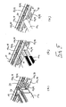
- a load securing rail 10 according to a first embodiment is shown, which is integrated into the side wall 12 of a commercial vehicle body or container and extends in the longitudinal direction of the commercial vehicle body or container preferably over its entire length.
- the load securing rail 10 as in Fig. 1 to 5 shown, vertically oriented.
- top and “bottom” used below refer to the vertical orientation of the load securing rail 10 shown in the figures.
- the load securing rail 10 is an extruded profile of anodized aluminum, which is basically produced in any length. It goes without saying that the load securing rail 10 may also be composed of several sections can be, as it is in the middle section of Fig. 4 is shown.
- the load securing rail 10 allows the anchoring of different load securing elements, such as a loading beam 14a (FIG. Fig. 5a ), a barrier bar 14b ( Fig. 5b ), a locking bar 14c ( Fig. 5c ) or a lashing strap, not shown.
- a loading beam 14a (FIG. Fig. 5a )
- a barrier bar 14b ( Fig. 5b )
- a locking bar 14c Fig. 5c
- lashing strap not shown.
- the load securing rail 10 on its front side on three different anchoring means receptacles 16 which define three mutually parallel and extending in the longitudinal direction of the load securing rail 10 anchoring lines.
- a first anchoring means receptacle 16a is formed by a double V-shaped cross-section anchoring groove 18 defined by a W-shaped rear wall portion 20 and two front wall portions 22 forming adjoining and undercuts. Between the front wall sections 22, the rear wall section 20 is formed into a central web 24, the front side of which terminates substantially flush with the front sides of the front wall sections 22.
- latching recesses 26 in the present embodiment, locking grooves distributed, which allow the latching of anchoring means of the load securing elements 14, for example, an anchor shoe 28 of the loading beam 14a (FIG. Fig. 5a ) or a buckle of a lashing strap.
- an anchor shoe 28 of the loading beam 14a FIG. Fig. 5a
- a buckle of a lashing strap By locking a load securing element 14 in the anchoring groove 18 is a correct Positioning of the load securing element 14 in the anchoring groove 18 not only relieved, but also permanently ensured.
- a second anchoring means receptacle 16b in the form of a substantially T-shaped anchoring groove 30 which is defined at its front by two spaced apart front wall sections 32.
- the upper of the front wall portions 32 of the T-shaped anchoring groove 30 passes into the lower of the front wall portions 22 of the double-V-shaped anchoring groove 18.
- the T-shaped anchoring groove 30 is bounded by a substantially plane rear wall 34 of the load securing rail 10. Upwards, i. Thus, the double-V-shaped anchoring groove 18, the T-shaped anchoring groove 30 is bounded by a portion 36 of the W-shaped rear wall portion 20. Downwardly, the T-shaped anchoring groove 30 is bounded by a support wall 38 extending between the front wall section 32 and the rear rear wall 34.
- the notches 40 are formed substantially circular, ie in both the upper and in the lower of the front wall portions 32 of the T-shaped anchoring groove 30 corresponding part-circular recesses 42 are formed.
- a third anchoring means receptacle 16c which comprises a multiplicity of anchoring windows 44 distributed in the longitudinal direction of the load securing rail 10, each having a substantially rectangular shape.
- the anchoring windows 44 are cut in a front wall portion 46 of the load securing rail 10, which merges into the lower of the T-shaped anchoring groove 30 bounding front wall portions 32.
- the anchoring windows 44 provide access to a hollow chamber 48 of the load securing rail 10 which is defined by the front wall section 46, the support wall 38, the rear wall 34 and a lower sloping outer wall 50 which connects the rear wall 34 to the front wall section 46.
- each of the anchoring means receptacles 16 is provided with drainage openings 52.
- the drainage holes 52 of the double V-shaped anchoring groove 18 have the shape of notches 53 which are cut from above into the lower of the front wall portions 22 and extend to the lower portion 36 of the W-shaped rear wall portion 20 in the front wall portion 22 ,
- the drainage openings 52 of the T-shaped anchoring groove 30 are formed by the notches 40, more precisely by the recesses 42 formed in the lower of the front wall sections 32.
- the notches 40 thus perform a dual function in this case, by not only immersing an anchoring means allow in the T-shaped anchoring groove 30, but also the drainage of water from the same.
- the recesses 42 in the lower of the front wall sections 32 have to be formed so deep for this purpose that they reach as far as the support wall 38.
- the support wall 38 is also inclined slightly downwardly toward the front of the load securing rail 10, similarly as the lower section 36 of the W-shaped rear wall section 20 of the double V-type. shaped anchoring groove 18th
- the drainage openings 52 of the anchoring windows 44 are formed by cutouts 54 at the lower edge of the anchoring windows 44. According to the above-described drainage openings 52, these cutouts 54 also extend downwards so far that they reach as far as the inclined outer wall 50. As Fig. 1 and 2 show, the inclined outer wall 50 has an inclination such that no water can collect in the hollow chamber 48, but instead exits via the cutouts 52 serving as recesses 54 of the anchoring window 44.
- An oblique outer wall 55 corresponding to the lower oblique outer wall 50 is also provided on the upper side of the load securing rail 10.
- This upper sloping outer wall 55 connects the rear wall 34 of the load securing rail 10 with the upper front wall portion 22 of the double V-shaped anchoring groove 18.
- the upper inclined outer wall 55 has an upper portion of the W-shaped rear wall portion 20 of the double V-shaped anchoring groove 18.
- the front side essentially flush with each other front wall sections 22, 32, 46 give the load securing rail together with the substantially planar rear wall 34 and the oblique outer walls 50, 55 a substantially trapezoidal outline.
- the side wall 12 of the vehicle body or container is provided with a mounting recess 56 for receiving the load securing rail 10, which also has a trapezoidal cross section, which is adapted to the contour of the load securing rail 10, that the front of the load securing rail 10 in the installed state is substantially flush with the front of the side wall 12 closes.
- the spacer protrusions 62 which resemble the ribs 58, also project outward from the outer front wall sections 22, 46, so that Similar gap regions 64 for adhesive also along the oblique outer walls 50, 55 and adjoining areas of the planar rear wall 34 extend.
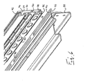
- a load securing rail according to a second embodiment is shown.
- the load securing rail 10 according to the second embodiment is formed substantially identical to the load securing rail 10 according to the first embodiment and differs from it ultimately only in that it is integrated into a substantially rectangular frame profile 70, in such a way that the load securing rail 10 a front side wall 72 of the frame profile forms.
- the frame profile 70 comprises a rear wall 74, which is connected via an upper wall 76 and a lower wall 78 with the load securing rail 10.
- To increase the stability of the frame profile 70 also extends a support strut 80 between the rear wall 74 and the rear wall 34 of the load securing rail 10th
- a plurality of elongated locking projections 82 are formed, which are distributed over the length of the frame profile 70.
- a latching projection extending continuously over the entire length of the frame profile 70.
- the locking projections 82 each have a cross-shaped cross-section, but other suitable cross-sections are conceivable.
- the load securing rail 10 can be mounted in a simple manner on a load compartment floor and used, for example, as a so-called beverage mat.
- a mounting bracket 86 may be attached to an end profile 88 of the load compartment floor ( Fig. 6 ), which is provided with elongated latching openings 90, in which the latching projections 82 of the frame profile 70 can be inserted and latched.
- the frame profile 70 On its upper wall 76, the frame profile 70 has an over the length of the frame profile 70 extending locking groove 92 which is adapted to the locking projections 82, so that a second load securing rail 10 of the same kind plugged or more load securing rails 10 can be assembled and locked together as it is in FIGS. 7 and 8 is shown.
- the cross-shaped detent projection 82 of the frame profile 70 is displaced laterally in the detent opening 90 of the mounting bracket 86 or in the detent groove 92 of a lower frame profile 70 this locked, that a lifting of the frame profile 70 is no longer possible.
Description
Die Erfindung betrifft eine Ladungssicherungsschiene zur Anbringung an einer Wand oder Decke eines Laderaums eines Transportfahrzeuges oder -behälters, welche eine Verankerungsmittelaufnahme eines ersten Typs umfasst, die eine sich in Längsrichtung der Ladungssicherungsschiene erstreckende erste Verankerungslinie definiert.The invention relates to a load securing rail for attachment to a wall or ceiling of a cargo space of a transport vehicle or container, which comprises an anchoring means receiving a first type, which defines a first anchoring line extending in the longitudinal direction of the load securing rail.
Ladungssicherungsschienen dieser Art sind grundsätzlich bekannt und werden auch als Anker- oder Zurrschienen bezeichnet. Sie dienen zur Sicherung von Ladung in Nutzfahrzeugaufbauten oder Containern, indem sie die Verankerung von Ladungssicherungselementen, wie beispielsweise von Zurrgurten oder Sperrstangen, ermöglichen. Üblicherweise sind herkömmliche Ladungssicherungsschienen jeweils für ein bestimmtes Verankerungssystem ausgelegt.Load securing rails of this type are basically known and are also referred to as anchor or Zurrschienen. They serve to secure cargo in commercial vehicle bodies or containers, by allowing the anchoring of cargo securing elements, such as lashing straps or locking bars. Usually, conventional load securing rails are each designed for a particular anchoring system.
Des Weiteren sind herkömmliche Ladungssicherungsschienen aus Edelstahl oder verzinktem Stahlblech hergestellt. Gerade letzteres Material erweist sich insofern als problematisch, als der Einsatz verzinkter Teile nach geltenden Hygienebestimmungen für die Beförderung von Lebensmitteln unerwünscht ist. Darüber hinaus sind Ladungssicherungsschienen mit galvanischem Überzug bei der Verwendung von chemischen Reinigungsmitteln und bei Beschädigung korrosionsgefährdet. Dementsprechend bereitet die Reinigung von Stahlschienen Probleme, vor allem können schwer zugängliche Stellen der Schienen, sogenannte tote Winkel, Brutstätten von Bakterien und Kleingetier sein. Davon abgesehen sind herkömmliche Stahlschienen nur in einer bestimmten Länge erhältlich, sodass bei einer Erstreckung der Ladungssicherungsschiene über die gesamte Länge eines Nutzfahrzeugaufbaus oder Containers unter Umständen eine Vielzahl von Schienenteilen aneinandergefügt werden müssen. Außerdem benötigen bekannte verzinkte Stahlschienen, wenn sie bündig mit einer Seitenwand eines Laderaums abschließen sollen, oben und unten zusätzliche Vertiefungen in der Seitenwand, in welchen sie verklebt und zusätzlich vernietet werden. Dabei müssen verzinkte Stahlschienen für den Klebevorgang vorbehandelt werden.Furthermore, conventional load securing rails are made of stainless steel or galvanized sheet steel. Especially the latter material proves to be problematic insofar as the use of galvanized parts according to applicable hygiene regulations for the transport of food is undesirable. In addition, galvanized load securing rails are prone to corrosion by the use of chemical cleaning agents and damage. Accordingly, the cleaning of steel rails causes problems, especially can be hard to reach places of the rails, so-called blind spots, breeding grounds of bacteria and small animals. Apart from that, conventional steel rails are only available in a certain length, so that an extension of the load securing rail over the entire length of a commercial vehicle body or container under certain circumstances, a plurality of rail parts must be joined together. In addition, known galvanized steel rails, if they are to be flush with a side wall of a cargo space, need additional recesses in the side wall at the top and bottom, in which they are glued and additionally riveted. In this case, galvanized steel rails must be pretreated for the gluing process.
Ladungssicherungsschienen mit mehreren parallel zueinander verlaufenden Verankerungslinien sind aus der
Der Erfindung liegt die Aufgabe zugrunde, eine Ladungssicherungsschiene zu schaffen, welche vielseitiger einsetzbar ist.The invention has for its object to provide a load securing rail, which is versatile.
Zur Lösung der Aufgabe ist eine Ladungssicherungsschiene mit den Merkmalen des Anspruchs 1 vorgesehen.To achieve the object, a load securing rail is provided with the features of claim 1.
Durch die Ausbildung der Ladungssicherungsschiene mit drei unterschiedlichen Verankerungsmittelaufnahmen ist die Ladungssicherungsschiene für die Verwendung von zumindest drei unterschiedlichen Verankerungssystemen vorbereitet, sodass sich die Ladungssicherungsschiene insgesamt vielseitiger einsetzen lässt und eine individuellere Sicherung von Ladung möglich ist. Man ist mit der Auswahl und dem Einbau der Ladungssicherungsschiene also nicht auf ein bestimmtes Verankerungssystem festgelegt, sondern kann nach Bedarf auf unterschiedliche Verankerungssysteme zurückgreifen.By forming the load securing rail with three different anchoring means receptacles, the load securing rail is prepared for the use of at least three different anchoring systems, so that the load securing rail can be used more versatile and a more individual securing of cargo is possible. It is therefore not limited to the selection and installation of the load securing rail on a particular anchoring system, but can fall back on different anchoring systems as needed.
Dadurch, dass die Verankerungslinien in Längsrichtung der Ladungssicherungsschiene verlaufen und sich die Verankerungsmittelaufnahmen insbesondere über die gesamte Länge der Ladungssicherungsschiene erstrecken, besteht je nach konkreter Ausbildung der Verankerungsmittelaufnahmen bzw. der zu verankernden Verankerungsmittel grundsätzlich die Möglichkeit, das Verankerungsmittel an einer beliebigen Längsposition der Ladungssicherungsschiene zu fixieren, wodurch die Flexibilität bei der Sicherung von Ladung erhöht ist.Due to the fact that the anchoring lines extend in the longitudinal direction of the load securing rail and the anchoring means receptacles extend over the entire length of the load securing rail in particular, depending on the specific design of the anchoring means receptacles or the anchoring means to be anchored, it is basically possible to fix the anchoring means at any longitudinal position of the load securing rail , which increases the flexibility in securing cargo.
Die verschiedenen Verankerungsmittelaufnahmen eignen sich besonders gut zur Verankerung von Zurrgurtschlössern, Lade- oder Sperrbalken oder Sperrstangen.The various anchoring device mounts are particularly suitable for anchoring lashing belt locks, loading or locking beams or locking bars.
Es versteht sich von selbst, dass die Reihenfolge der Anordnung der verschiedenen Verankerungsmittelaufnahmen grundsätzlich beliebig ist. Das heißt, dass nicht notwendigerweise die T-förmige Verankerungsnut zwischen der doppel-V-förmigen Verankerungsnut und den Verankerungsfenstern angeordnet sein muss. Ebenso ist es möglich, die doppel-V-förmige Verankerungsnut zwischen der T-förmigen Verankerungsnut und den Verankerungsfenstern vorzusehen oder die Verankerungsfenster zwischen der doppel-V-förmigen Verankerungsnut und der T-förmigen Verankerungsnut anzuordnen.It goes without saying that the order of arrangement of the various anchoring means shots is basically arbitrary. That is, the T-shaped anchoring groove does not necessarily have to be located between the double V-shaped anchoring groove and the anchoring windows. It is also possible to provide the double V-shaped anchoring groove between the T-shaped anchoring groove and the anchoring windows or to arrange the anchoring windows between the double V-shaped anchoring groove and the T-shaped anchoring groove.
Vorteilhafte Ausbildungen der Erfindung sind den Unteransprüchen, der Beschreibung und der Zeichnung zu entnehmen.Advantageous embodiments of the invention are described in the dependent claims, the description and the drawings.
Gemäß einer bevorzugten Ausführungsform sind die Verankerungsmittelaufnahmen mit Ablauföffnungen versehen, durch welche Flüssigkeit aus den Verankerungsmittelaufnahmen ablaufen kann. Beispielsweise kann mindestens eine Ablauföffnung in einem unteren der vorderen Wandabschnitte der doppel-V-förmigen und/oder T-förmigen Verankerungsnut und/ oder an einer Unterseite wenigstens eines Verankerungsfensters vorgesehen sein. Die Ablauföffnungen ermöglichen das Ablaufen von Schmutzwasser aus der Ladungssicherungsschiene nach einer Reinigung derselben mittels beispielsweise eines Dampf-Hochdruckreinigers. Die Ladungssicherungsschiene lässt sich auf diese Weise leicht und zuverlässig sauber halten, insbesondere wird die Ansammlung von Bakterien und Kleingetier wirksam verhindert. Die Ladungssicherungsschiene erleichtert somit die Einhaltung von Hygienebestimmungen, wie sie beispielsweise für den Transport von Lebensmitteln gelten.According to a preferred embodiment, the anchoring means receptacles are provided with drain openings through which liquid can drain from the anchoring means receptacles. For example, at least one drain opening may be provided in a lower one of the front wall sections of the double V-shaped and / or T-shaped anchoring groove and / or on an underside of at least one anchoring window. The drainage holes allow drainage of dirty water from the load securing rail after cleaning the same by means of, for example, a high-pressure steam cleaner. The load securing rail can be easily and reliably kept clean in this way, in particular, the accumulation of bacteria and small animals is effectively prevented. The load securing rail thus facilitates compliance with hygiene requirements, as they apply, for example, for the transport of food.
Vorteilhafterweise bildet eine Ablauföffnung einer Verankerungsnut gleichzeitig einen Teil einer Ausklinkung zum Einsetzen eines Verankerungsmittels in die Verankerungsnut. Die Ablauföffnung erfüllt in diesem Fall eine Doppelfunktion, indem sie zum einen als Eintauchöffnung für das Einsetzen eines Verankerungsmittels dient und gleichzeitig das Ablaufen von Schmutzwasser ermöglicht. Eine zusätzliche Eintauchöffnung oder Ausklinkung braucht in diesem Fall also nicht vorgesehen zu werden.Advantageously, a drain opening of an anchoring groove simultaneously forms part of a notch for inserting an anchoring means into the anchoring groove. In this case, the drainage opening fulfills a double function, on the one hand serving as an insertion opening for the insertion of an anchoring means and at the same time allowing drainage of dirty water. An additional immersion opening or notch does not need to be provided in this case.
Gemäß einer vorteilhaften Ausführungsform ist die Ladungssicherungsschiene durch ein Strangprofil, insbesondere aus Aluminium, bevorzugt eloxiertem Aluminium, gebildet. Aufgrund dieses Materials ist die Ladungssicherungsschiene nicht nur lebensmitteltauglich, sondern sie lässt sich als Strangprofil in grundsätzlich beliebiger Länge einstückig herstellen. Auf diese Weise ist es möglich, einen Nutzfahrzeugaufbau oder Container über seine gesamte Länge gesehen mit einer einstückigen Ladungssicherungsschiene auszustatten, was bei gleichzeitig vereinfachter Montage zu einer erhöhten Stabilität beiträgt und somit letztlich eine erhöhte Ladungssicherheit gewährleistet.According to an advantageous embodiment, the load securing rail is preferred by an extruded profile, in particular made of aluminum anodized aluminum, formed. Because of this material, the load securing rail is not only suitable for foodstuffs, but can be produced as an extruded profile in basically any length in one piece. In this way, it is possible to equip a commercial vehicle body or container over its entire length with a one-piece load securing rail, which at the same time simplifies installation contributes to increased stability and thus ultimately ensures increased cargo security.
Bevorzugt weist die Ladungssicherungsschiene im Querschnitt gesehen einen im Wesentlichen trapezförmigen Umriss auf, dessen längere Grundseite die Vorderseite der Ladungssicherungsschiene bildet, d.h. also die Seite, über welche die Verankerungsmittelaufnahmen zugänglich sind. Der trapezförmig Umriss der Ladungssicherungsschiene ermöglicht eine zuverlässigere Montage der Ladungssicherungsschiene in der Wand eines Nutzfahrzeugaufbaus oder Containers und insbesondere eine optimierte Übertragung der Kräfte, die von in der Ladungssicherungsschiene verankerten Ladungssicherungselementen auf die Ladungssicherungsschiene ausgeübt werden, auf die Wand. Im Ergebnis trägt der trapezförmige Umriss der Ladungssicherungsschiene also zu einer zuverlässigeren Ladungssicherung bei.Preferably, the load securing rail seen in cross section on a substantially trapezoidal outline, whose longer base side forms the front of the load securing rail, i. that is, the side over which the anchoring means receptacles are accessible. The trapezoidal outline of the load securing rail allows a more reliable mounting of the load securing rail in the wall of a commercial vehicle body or container and in particular an optimized transmission of the forces exerted on the load securing rail by load securing elements anchored in the load securing rail to the wall. As a result, the trapezoidal outline of the load securing rail thus contributes to a more reliable load securing.
Die Ladungssicherungsschiene kann beispielsweise in eine an den trapezförmigen Umriss der Ladungssicherungsschiene angepasste Mulde in der Wand eines Nutzfahrzeugaufbaus oder Containers eingeklebt sein. Um zu verhindern, dass der Klebestoff durch ein Hineindrücken der Ladungssicherungsschiene in die Mulde verdrängt und die effektive Klebefläche reduziert wird, ist an einer Rückseite der Ladungssicherungsschiene vorteilhafterweise wenigstens eine sich in Längsrichtung der Ladungssicherungsschiene erstreckende Rippe ausgebildet. Alternativ oder zusätzlich kann jeweils ein sich in Längsrichtung der Ladungssicherungsschiene erstreckender Vorsprung in an die Vorderseite angrenzenden Bereichen von Schrägseiten der Ladungssicherungsschiene ausgebildet sein. Die Vorsprünge bzw. die Rippe verhindern, dass die Rückseite und die schrägen Seiten der Ladungssicherungsschiene plan an der die Mulde begrenzenden Wandoberfläche anliegen und wirken somit gewissermaßen als Abstandshalter, welche großflächige Spaltbereiche zwischen der Ladungssicherungsschiene und der Wand definieren, in denen sich Klebstoff sammeln und eine großflächige und zuverlässige Verklebung der Ladungssicherungsschiene in der Wand gewährleisten kann.The load securing rail can, for example, be glued into a recess adapted to the trapezoidal contour of the load securing rail in the wall of a commercial vehicle body or container. In order to prevent the adhesive from being displaced into the depression by pushing in the load securing rail and the effective adhesive surface being reduced, at least one rib extending in the longitudinal direction of the load securing rail is advantageously formed on a rear side of the load securing rail. Alternatively or in addition In each case, a projection extending in the longitudinal direction of the load securing rail can be formed in areas of oblique sides of the load securing rail adjoining the front side. The projections or rib prevent the back and oblique sides of the load securing rail from abutting flat against the wall surface delimiting the well and thus effectively acting as spacers defining large gap areas between the load securing rail and the wall in which glue collects and a ensure large-area and reliable adhesion of the load securing rail in the wall.
Gemäß einer weiteren Ausführungsform bildet die Ladungssicherungsschiene eine Wand eines im Wesentlichen rechteckigen Profilrahmens. In dieser Variante lässt sich die Ladungssicherungsschiene im Randbereich eines Laderaumbodens montieren, beispielsweise als sogenannte Getränkelatte, um zu verhindern, dass Ladung, z.B. Getränkekisten, seitlich aus dem Laderaum herausrutschen können.According to a further embodiment, the load securing rail forms a wall of a substantially rectangular profile frame. In this variant, the load securing rail can be mounted in the edge region of a load compartment floor, for example as a so-called beverage mat, in order to prevent cargo, e.g. Beverage crates, can slip sideways out of the hold.
Zur Erhöhung der Steifigkeit und somit der Stabilität des Profilrahmens ist vorteilhafterweise eine Stützstrebe zwischen der Ladungssicherungsschiene und einer gegenüberliegenden Wand des Profilrahmens ausgebildet.To increase the rigidity and thus the stability of the profile frame advantageously a support strut between the load securing rail and an opposite wall of the profile frame is formed.
Zur einfachen Montage bzw. Demontage der Ladungssicherungsschiene am Laderaumboden ist bevorzugt wenigstens ein, insbesondere sich in Längsrichtung erstreckender Rastvorsprung, an einer Unterseite des Profilrahmens ausgebildet, welcher ein einfaches Einstecken des Profilrahmens in eine am Laderaumboden entsprechend vorgesehene Rastöffnung ermöglicht. Der Rastvorsprung erstreckt sich bevorzugt über die gesamte Länge des Profilrahmens und kann entweder durchgehend ausgebildet oder in längliche Abschnitte unterteilt sein. Der Rastvorsprung kann beispielsweise ein kreuzförmiges Querschnittsprofil aufweisen.For easy assembly and disassembly of the load securing rail on the load compartment floor at least one, in particular extending in the longitudinal direction latching projection is preferably formed on an underside of the profile frame, which allows easy insertion of the profile frame in a correspondingly provided on the load compartment floor latching opening. The latching projection preferably extends over the entire length of the profile frame and can either be continuous or divided into elongated sections. The latching projection may, for example, have a cross-shaped cross-sectional profile.
Vorteilhafterweise ist eine, insbesondere an den Rastvorsprung angepasste, Rastnut an einer Oberseite des Profilrahmens ausgebildet. Diese ermöglicht es, mehrere Profilrahmen übereinander zu stecken und somit die Gesamthöhe der Ladungssicherungsschiene nach Bedarf zu erhöhen. Dabei sind der Rastvorsprung und die Rastnut in ihrer Form bevorzugt derart ausgebildet, dass der Rastvorsprung im in die Rastnut eingetauchten Zustand bei Belastung der Ladungssicherungsschiene durch Ladung eine Verriegelung in der Rastnut erfährt, so dass die zusammengesteckten Profilrahmen auch unter Last sicher miteinander verbunden sind.Advantageously, a, in particular adapted to the latching projection, locking groove is formed on an upper side of the profile frame. This makes it possible to superimpose several profile frames one above the other and thus to increase the overall height of the load securing rail as needed. In this case, the latching projection and the latching groove are preferably formed in such a form that the latching projection in the immersed in the latching state under load of the load securing rail by loading undergoes a lock in the locking groove, so that the mated profile frame are securely connected to each other even under load.
Nachfolgend wird die Erfindung rein beispielhaft anhand vorteilhafter Ausführungsformen unter Bezugnahme auf die beigefügte Zeichnung beschrieben. Es zeigen:
- Fig. 1
- eine Querschnittsansicht einer in eine Wand eingebauten ersten Ausführungsform einer erfindungsgemäßen Ladungssicherungsschiene;
- Fig. 2
- eine perspektivische Schnittansicht der Ladungssicherungsschiene von
Fig. 1 ; - Fig. 3
- eine Draufsicht auf die Vorderseite der Ladungssicherungsschiene von
Fig. 1 ; - Fig. 4
- perspektivische Ansichten verschiedener Teilausschnitte der Ladungssicherungsschiene von
Fig. 1 ; - Fig. 5
- Ausschnitte der Ladungssicherungsschiene von
Fig. 1 mit unterschiedlichen Ladungssicherungselementen; - Fig. 6
- eine perspektivische Schnittansicht einer zweiten Ausführungsform einer erfindungsgemäßen Ladungssicherungsschiene und eines an einem Abschlussprofil eines Laderaumbodens befestigten Montagewinkels;
- Fig. 7
- eine Querschnittsansicht zweier aufeinander gesteckter Ladungssicherungsschienen von
Fig. 6 ; und - Fig. 8
- die Ladungssicherungsschienen von
Fig. 7 in perspektivischer Schnittansicht.
- Fig. 1
- a cross-sectional view of a built-in wall in a first embodiment of a load securing rail according to the invention;
- Fig. 2
- a sectional perspective view of the load securing rail of
Fig. 1 ; - Fig. 3
- a plan view of the front of the load securing rail of
Fig. 1 ; - Fig. 4
- perspective views of different partial sections of the load securing rail of
Fig. 1 ; - Fig. 5
- Cutouts of the load securing rail of
Fig. 1 with different load securing elements; - Fig. 6
- a sectional perspective view of a second embodiment of a load securing rail according to the invention and a mounting bracket attached to a terminal profile of a load compartment floor;
- Fig. 7
- a cross-sectional view of two stacked load securing rails of
Fig. 6 ; and - Fig. 8
- the load securing rails of
Fig. 7 in a perspective sectional view.
In
Bei der Ladungssicherungsschiene 10 handelt es sich um ein Strangprofil aus eloxiertem Aluminium, welches grundsätzlich in beliebiger Länge herstellbar ist. Es versteht sich aber von selbst, dass die Ladungssicherungsschiene 10 unter Umständen auch aus mehreren Teilstücken zusammengesetzt werden kann, wie es in dem mittleren Ausschnitt von
Die Ladungssicherungsschiene 10 ermöglicht die Verankerung unterschiedlicher Ladungssicherungselemente, wie beispielsweise eines Ladebalkens 14a (
Zur Verankerung dieser Ladungssicherungselemente 14 weist die Ladungssicherungsschiene 10 an ihrer Vorderseite drei verschiedene Verankerungsmittelaufnahmen 16 auf, welche drei parallel zueinander verlaufende und sich in Längsrichtung der Ladungssicherungsschiene 10 erstreckende Verankerungslinien definieren.To anchor these cargo securing elements 14, the
Eine erste Verankerungsmittelaufnahme 16a ist durch eine Verankerungsnut 18 mit doppel-V-förmigen Querschnitt gebildet, welcher durch einen W-förmigen hinteren Wandabschnitt 20 und zwei sich daran anschließende und Hinterschneidungen bildende vordere Wandabschnitte 22 definiert ist. Zwischen den vorderen Wandabschnitten 22 ist der hintere Wandabschnitt 20 zu einem mittleren Steg 24 ausgeformt, dessen Vorderseite mit den Vorderseiten der vorderen Wandabschnitte 22 im Wesentlichen bündig abschließt.A first anchoring means
Entlang des mittleren Steges 24 sind Rastvertiefungen 26, im vorliegenden Ausführungsbeispiel Rastnuten, verteilt angeordnet, welche die Einrastung von Verankerungsmitteln der Ladungssicherungselemente 14 ermöglichen, z.B. eines Verankerungsschuhs 28 des Ladebalkens 14a (
Unterhalb der doppel-V-förmigen Verankerungsnut 18 verläuft eine zweite Verankerungsmittelaufnahme 16b in der Gestalt einer im Wesentlichen T-förmigen Verankerungsnut 30, die an ihrer Vorderseite durch zwei zueinander beabstandete vordere Wandabschnitte 32 definiert ist. Der obere der vorderen Wandabschnitte 32 der T-förmigen Verankerungsnut 30 geht dabei in den unteren der vorderen Wandabschnitte 22 der doppel-V-förmigen Verankerungsnut 18 über.Below the double-V-shaped
An ihrer Rückseite ist die T-förmige Verankerungsnut 30 durch eine im Wesentlichen plane Rückwand 34 der Ladungssicherungsschiene 10 begrenzt. Nach oben, d.h. also zur doppel-V-förmigen Verankerungsnut 18 hin, ist die T-förmige Verankerungsnut 30 durch einen Teilabschnitt 36 des W-förmigen hinteren Wandabschnitts 20 begrenzt. Nach unten ist die T-förmige Verankerungsnut 30 durch eine sich zwischen dem vorderen Wandabschnitt 32 und der hinteren Rückwand 34 erstreckende Stützwand 38 begrenzt.At its rear side, the T-shaped anchoring groove 30 is bounded by a substantially plane
Entlang der T-förmigen Verankerungsnut 30 verteilt sind eine Vielzahl von Ausklinkungen 40 in die vorderen Wandabschnitte 32 eingeschnitten, welche das Eintauchen eines Verankerungsmittels eines Ladungssicherungselements 14 in die T-förmige Verankerungsnut 30 ermöglichen. Im vorliegenden Ausführungsbeispiel sind die Ausklinkungen 40 im Wesentlichen kreisförmig ausgebildet, d.h. sowohl in dem oberen als auch in dem unteren der vorderen Wandabschnitte 32 der T-förmigen Verankerungsnut 30 sind entsprechende teilkreisförmige Aussparungen 42 ausgebildet.Distributed along the T-shaped anchoring groove 30 are a plurality of notches 40 cut into the
Unterhalb der zweiten Verankerungsmittelaufnahme 16b ist eine dritte Verankerungsmittelaufnahme 16c ausgebildet, welche eine Vielzahl von in Längsrichtung der Ladungssicherungsschiene 10 verteilt angeordneten Verankerungsfenstern 44 umfasst, die jeweils eine im Wesentlichen rechteckige Form aufweisen. Die Verankerungsfenster 44 sind in einen vorderen Wandabschnitt 46 der Ladungssicherungsschiene 10 eingeschnitten, welcher in den unteren der die T-förmige Verankerungsnut 30 begrenzenden vorderen Wandabschnitte 32 übergeht.Below the second anchoring means receptacle 16b, a third anchoring means
Die Verankerungsfenster 44 gewähren Zugang zu einer Hohlkammer 48 der Ladungssicherungsschiene 10, welche durch den vorderen Wandabschnitt 46, die Stützwand 38, die Rückwand 34 und eine untere schräge Außenwand 50 definiert ist, welche die Rückwand 34 mit dem vorderen Wandabschnitt 46 verbindet.The anchoring
Wird die Ladungssicherungsschiene 10 in einem zum Transport von Lebensmitteln vorgesehenen Fahrzeugaufbau oder Container eingesetzt, so kann es aufgrund von Hygienebestimmungen erforderlich sein, die Seitenwand 12 und somit auch die Ladungssicherungsschiene 10 von Zeit zu Zeit zu reinigen, was üblicherweise mit einem Dampf-Hochdruckreiniger geschieht. Damit Schmutzwasser nach einem Reinigungsvorgang aus den Verankerungsmittelaufnahmen 16 ablaufen kann, ist jede der Verankerungsmittelaufnahmen 16 mit Ablauföffnungen 52 versehen.If the
Die Ablauföffnungen 52 der doppel-V-förmigen Verankerungsnut 18 besitzen die Gestalt von Kerben 53, die von oben in den unteren der vorderen Wandabschnitte 22 eingeschnitten sind und bis zu dem unteren Teilabschnitt 36 des W-förmigen hinteren Wandabschnitts 20 in den vorderen Wandabschnitt 22 hineinreichen.The drainage holes 52 of the double V-shaped
Die Ablauföffnungen 52 der T-förmigen Verankerungsnut 30 sind durch die Ausklinkungen 40 gebildet, genauer gesagt durch die in dem unteren der vorderen Wandabschnitte 32 ausgebildeten Aussparungen 42. Die Ausklinkungen 40 erfüllen in diesem Fall also eine Doppelfunktion, indem sie nicht nur das Eintauchen eines Verankerungsmittels in die T-förmige Verankerungsnut 30 ermöglichen, sondern auch das Ablaufen von Wasser aus derselben. Es versteht sich von selbst, dass die Aussparungen 42 in dem unteren der vorderen Wandabschnitte 32 hierzu so tief ausgebildet sein müssen, dass sie bis an die Stützwand 38 heranreichen. Um das Ablaufen von Wasser aus der T-förmigen Verankerungsnut 30 zu erleichtern, ist die Stützwand 38 außerdem zur Vorderseite der Ladungssicherungsschiene 10 hin leicht nach unten geneigt, ähnlich wie auch der untere Teilabschnitt 36 des W-förmigen hinteren Wandabschnitts 20 der doppel-V-förmigen Verankerungsnut 18.The drainage openings 52 of the T-shaped anchoring groove 30 are formed by the notches 40, more precisely by the recesses 42 formed in the lower of the
Die Ablauföffnungen 52 der Verankerungsfenster 44 sind durch Ausfräsungen 54 am unteren Rand der Verankerungsfenster 44 gebildet. Entsprechend den voranstehend beschriebenen Ablauföffnungen 52 erstrecken sich auch diese Ausfräsungen 54 so weit nach unten, dass sie bis an die schräge Außenwand 50 heranreichen. Wie
Eine der unteren schrägen Außenwand 50 entsprechende schräge Außenwand 55 ist auch an der Oberseite der Ladungssicherungsschiene 10 vorgesehen. Diese obere schräge Außenwand 55 verbindet die Rückwand 34 der Ladungssicherungsschiene 10 mit dem oberen vorderen Wandabschnitt 22 der doppel-V-förmigen Verankerungsnut 18. Gleichzeitig bildet die obere schräge Außenwand 55 einen oberen Teilabschnitt des W-förmigen hinteren Wandabschnitts 20 der doppel-V-förmigen Verankerungsnut 18.An oblique
Die vorderseitig im Wesentlichen bündig miteinander abschließenden vorderen Wandabschnitte 22, 32, 46 verleihen der Ladungssicherungsschiene zusammen mit der im Wesentlichen planen Rückwand 34 und den schrägen Außenwänden 50, 55 einen im Wesentlichen trapezförmigen Umriss.The front side essentially flush with each other
Die Seitenwand 12 des Fahrzeugaufbaus oder Containers ist mit einer Montagemulde 56 zur Aufnahme der Ladungssicherungsschiene 10 versehen, welche einen ebenfalls trapezförmigen Querschnitt aufweist, der so an den Umriss der Ladungssicherungsschiene 10 angepasst ist, dass die Vorderseite der Ladungssicherungsschiene 10 im eingebauten Zustand im Wesentlichen bündig mit der Vorderseite der Seitenwand 12 abschließt.The
Die Befestigung der Ladungssicherungsschiene 10 in der Seitenwand 12 erfolgt mittels eine Klebstoffs. Um zu verhindern, dass der Klebstoff beim Hineindrücken der Ladungssicherungsschiene 10 in die Montagemulde 56 aus dieser verdrängt und somit die effektive Klebefläche minimiert wird, sind an der Rückwand 34 der Ladungssicherungsschiene 10 zwei sich in Längsrichtung der Ladungssicherungsschiene 10 erstreckende Rippen 58 ausgebildet, welche im eingebauten Zustand der Ladungssicherungsschiene 10 einen Spaltbereich 60 zwischen sich, der Rückwand 34 der Ladungssicherungsschiene 10 und der die Montagemulde 56 begrenzenden Wandoberfläche definieren, in welchem sich Klebstoff sammeln kann.The attachment of the
Den Rippen 58 ähnelnde Abstandshaltevorsprünge 62 gehen auch aus den äußeren vorderen Wandabschnitten 22, 46 nach außen hervor, sodass ähnliche Spaltbereiche 64 für Klebstoff auch entlang den schrägen Außenwänden 50, 55 und sich daran anschließenden Bereichen der planen Rückwand 34 erstrecken. Durch den in den Spaltbereichen 60, 64 gehaltenen Klebstoff kann eine großflächige und zuverlässige Verklebung der Ladungssicherungsschiene 10 mit der Seitenwand 12 und somit letztlich eine sichere und stabile Befestigung der Ladungssicherungsschiene 10 in der Seitenwand 12 erreicht werden.The spacer protrusions 62, which resemble the
In
An der unteren Wand 78 des Rahmenprofils 70 sind mehrere längliche Rastvorsprünge 82 ausgebildet, welche über die Länge des Rahmenprofils 70 verteilt angeordnet sind. Grundsätzlich ist es auch denkbar, einen sich über die gesamte Länge des Rahmenprofils 70 durchgehend erstreckenden Rastvorsprung vorzusehen.On the
Bei dem dargestellten Ausführungsbeispiel weisen die Rastvorsprünge 82 jeweils einen kreuzförmigen Querschnitt auf, wobei aber auch andere geeignete Querschnitte vorstellbar sind.In the illustrated embodiment, the locking
Mit Hilfe der Rastvorsprünge 82 lässt sich die Ladungssicherungsschiene 10 auf einfache Weise an einem Laderaumboden montieren und beispielsweise als sogenannte Getränkelatte verwenden. Zur Befestigung der Ladungssicherungsschiene 10 an dem Laderaumboden kann beispielsweise ein Montagewinkel 86 an einem Abschlussprofil 88 des Laderaumbodens angebracht sein (
An seiner oberen Wand 76 weist das Rahmenprofil 70 eine sich über die Länge des Rahmenprofils 70 erstreckende Rastnut 92 auf, welche an die Rastvorsprünge 82 angepasst ist, sodass eine zweite Ladungssicherungsschiene 10 der gleichen Art aufgesteckt bzw. mehrere Ladungssicherungsschienen 10 zusammengefügt und miteinander verrastet werden können, wie es in
Erfährt die Ladungssicherungsschiene 10 eines Rahmenprofils 70 Druck durch Ladung oder durch eine Palette oder Zug durch ein Zurrmittel, wird der kreuzförmige Rastvorsprung 82 des Rahmenprofils 70 in der Rastöffnung 90 des Montagewinkels 86 bzw. in der Rastnut 92 eines unteren Rahmenprofils 70 seitlich derart verschoben und in dieser verriegelt, dass ein Ausheben des Rahmenprofils 70 nicht mehr möglich ist.If the
- 1010
- LadungssicherungsschieneLoad safety rails
- 1212
- SeitenwandSide wall
- 1414
- LadungssicherungselementLoad securing element
- 14a14a
- Ladebalkenloading bar
- 14b14b
- SperrbalkenLoad bar
- 14c14c
- Sperrstangelocking bar
- 1616
- VerankerungsmittelaufnahmeAnchoring borrowing
- 1818
- doppel-V-förmige Verankerungsnutdouble V-shaped anchoring groove
- 2020
- hinterer Wandabschnittrear wall section
- 2222
- vorderer Wandabschnittfront wall section
- 2424
- mittlerer Stegmiddle jetty
- 2626
- Rastvertiefunglatching depression
- 2828
- Verankerungsschuhanchor shoe
- 3030
- T-förmige VerankerungsnutT-shaped anchoring groove
- 3232
- vorderer Wandabschnittfront wall section
- 3434
- Rückwandrear wall
- 3636
- Teilabschnittpart Of
- 3838
- Stützwandretaining wall
- 4040
- Ausklinkungnotch
- 4242
- Aussparungrecess
- 4444
- Verankerungsfensteranchor window
- 4646
- vorderer Wandabschnittfront wall section
- 4848
- Hohlkammerhollow
- 5050
- schräge Außenwandsloping outer wall
- 5252
- Ablauföffnungdrain hole
- 5353
- Kerbescore
- 5454
- Ausfräsungcountersink
- 5555
- schräge Außenwandsloping outer wall
- 5656
- Montagemuldemounting recess
- 5858
- Ripperib
- 6060
- Spaltbereichgap region
- 6262
- AbstandshaltevorsprungSpacing holding projection
- 6464
- Spaltbereichgap region
- 7070
- Rahmenprofilframe profile
- 7272
- vordere Seitenwandfront side wall
- 7474
- hintere Wandrear wall
- 7676
- obere Wandupper wall
- 7878
- untere Wandbottom wall
- 8080
- Stützstrebesupport strut
- 8282
- Rastvorsprungcatch projection
- 8686
- Montagewinkelmounting Brackets
- 8888
- AbschlussprofilEnd profile
- 9090
- Rastöffnunglatching opening
- 9292
- Rastnutlocking groove
Claims (12)
- A load securing rail (10) for attachment to a wall (12) or to a ceiling of a loading space of a transport vehicle or transport container comprising
an anchorage means receiver (16) of a first type which comprises an anchorage groove (18) having a double V-shaped cross-section and which defines a first anchorage line extending in the longitudinal direction of the load securing rail (10);
an anchorage means receiver (16) of a second type which is different from the first type, with the anchorage means receiver (16) of the second type comprising a substantially T-shaped anchorage groove (30) which is defined at its front side by two mutually spaced apart front wall sections (32) and defining a second anchorage line which extends substantially in parallel with the first anchorage line; and
an anchorage means receiver (16) of a third type which is different from the first and second types, with the anchorage means receiver (16) of the third type comprising a plurality of mutually spaced apart anchorage windows (44) and defining a third anchorage line which extends substantially in parallel with the first and second anchorage lines. - A load securing rail (10) in accordance with claim 1,
characterised in that
the anchorage means receivers (16) are provided with outflow openings (52) through which liquid can flow out of the anchorage means receivers (16). - A load securing rail (10) in accordance with one of the preceding claims,
characterised in that
an outflow opening (52) of an anchorage groove (30) forms a part of a notch (40) for the insertion of an anchorage means into the anchorage groove (30). - A load securing rail (10) in accordance with any one of the preceding claims,
characterised in that
it is formed by an extruded section, in particular composed of aluminium, preferably of anodised aluminium. - A load securing rail (10) in accordance with any one of the preceding claims,
characterised in that
it has a substantially trapezoidal outline viewed in cross-section, with the longer base side of said outline forming a front side of the load securing rail (10) allowing access to the anchorage means receivers (16). - A load securing rail (10) in accordance with claim 5,
characterised in that
at least one rib (58) which extends in the longitudinal direction of the load securing rail (10) is formed at a rear side of the load securing rail; and/or
in that a respective projection (62) which extends in the longitudinal direction of the load securing rail (10) is formed in regions of oblique sides of the load securing rail (10) adjacent to the front side. - A load securing rail (10) in accordance with any one of the preceding claims,
characterised in that
it forms a wall of a substantially rectangular frame section (70). - A load securing rail (10) in accordance with claim 7,
characterised in that
at least one latch projection (82), in particular a latch projection extending in the longitudinal direction, is formed at a lower side of the frame section (70). - A load securing rail (10) in accordance with claim 7 or claim 8,
characterised in that
a latch groove (92), in particular a latch groove matched to the latch projection (82), extending in the longitudinal direction is formed at an upper side of the frame section (70). - A load securing rail (10) in accordance with claim 8 or claim 9,
characterised in that
the latch projection (82) is configured and in partiuclar has a cruciform cross-sectional section such that it latches automatically in a latch groove (92) or latch opening (90) under load. - A load securing rail (10) in accordance with any one of the preceding claims,
characterised in that
the anchorage groove (18) having a double V-shaped cross-section is defined by a W-shaped rear wall section (20) and by two front wall sections (22) adjoining the former and forming undercuts. - A load securing rail (10) in accordance with claim 11,
characterised in that
the rear wall section (20) is formed between the front wall sections (22) to form a middle web (24) whose front side terminates substantially flush with the front sides of the front wall sections (22).
Priority Applications (3)
| Application Number | Priority Date | Filing Date | Title |
|---|---|---|---|
| PL11010064T PL2474444T3 (en) | 2011-01-11 | 2011-12-21 | Load securing rail |
| PL13153594T PL2591951T3 (en) | 2011-01-11 | 2011-12-21 | Load securing rail |
| EP13153594.0A EP2591951B8 (en) | 2011-01-11 | 2011-12-21 | Load securing rail |
Applications Claiming Priority (1)
| Application Number | Priority Date | Filing Date | Title |
|---|---|---|---|
| DE102011008254A DE102011008254A1 (en) | 2011-01-11 | 2011-01-11 | Load safety rails |
Related Child Applications (2)
| Application Number | Title | Priority Date | Filing Date |
|---|---|---|---|
| EP13153594.0A Division EP2591951B8 (en) | 2011-01-11 | 2011-12-21 | Load securing rail |
| EP13153594.0A Division-Into EP2591951B8 (en) | 2011-01-11 | 2011-12-21 | Load securing rail |
Publications (2)
| Publication Number | Publication Date |
|---|---|
| EP2474444A1 EP2474444A1 (en) | 2012-07-11 |
| EP2474444B1 true EP2474444B1 (en) | 2014-07-02 |
Family
ID=45470183
Family Applications (2)
| Application Number | Title | Priority Date | Filing Date |
|---|---|---|---|
| EP13153594.0A Not-in-force EP2591951B8 (en) | 2011-01-11 | 2011-12-21 | Load securing rail |
| EP11010064.1A Not-in-force EP2474444B1 (en) | 2011-01-11 | 2011-12-21 | Load securing rail |
Family Applications Before (1)
| Application Number | Title | Priority Date | Filing Date |
|---|---|---|---|
| EP13153594.0A Not-in-force EP2591951B8 (en) | 2011-01-11 | 2011-12-21 | Load securing rail |
Country Status (5)
| Country | Link |
|---|---|
| EP (2) | EP2591951B8 (en) |
| CN (2) | CN105644416A (en) |
| DE (1) | DE102011008254A1 (en) |
| ES (2) | ES2551272T3 (en) |
| PL (2) | PL2591951T3 (en) |
Cited By (1)
| Publication number | Priority date | Publication date | Assignee | Title |
|---|---|---|---|---|
| DE102016109634B4 (en) | 2016-05-25 | 2020-07-30 | Schmitz Cargobull Aktiengesellschaft | Load securing hooks for connecting a holding means to a load securing rail, as well as load securing means and the construction of a commercial vehicle, each with the load securing hook |
Families Citing this family (9)
| Publication number | Priority date | Publication date | Assignee | Title |
|---|---|---|---|---|
| WO2015127946A1 (en) * | 2014-02-27 | 2015-09-03 | Wolfgang Rixen | Mounting plate |
| DE202015102860U1 (en) | 2015-06-02 | 2015-06-25 | Kiesling Fahrzeugbau Gmbh | Load securing system for a cargo structure of a commercial vehicle |
| DE102015108731B4 (en) | 2015-06-02 | 2023-06-07 | Kiesling Fahrzeugbau Gmbh | Load securing system for a load structure of a commercial vehicle |
| GB2550609A (en) * | 2016-05-25 | 2017-11-29 | Loadlok Mfg Limited | Restraint track |
| EP3248837B1 (en) | 2016-05-25 | 2020-08-12 | Schmitz Cargobull AG | Box body of a commercial vehicle with load securing rail |
| DE102017206874A1 (en) * | 2017-04-24 | 2018-10-25 | Volkswagen Aktiengesellschaft | Lashing rail, loading area, vehicle |
| EP3590800A1 (en) * | 2018-07-06 | 2020-01-08 | Schmitz Cargobull AG | Box body for a commercial vehicle provided with load securing profile |
| DE202021103984U1 (en) | 2021-07-27 | 2021-10-29 | CliXBond GmbH | Anchor rail in a truck body |
| DE102021128297A1 (en) * | 2021-10-29 | 2023-05-04 | Kögel Trailer GmbH | Holding device, system, structure and method |
Citations (3)
| Publication number | Priority date | Publication date | Assignee | Title |
|---|---|---|---|---|
| US20090003958A1 (en) * | 2007-06-27 | 2009-01-01 | Knox Howard Thomas | Anchor lock tether fitting |
| US7556463B1 (en) * | 2005-06-06 | 2009-07-07 | Hall Kennith C | Mounting structure |
| DE102008058006B3 (en) * | 2008-11-19 | 2010-08-26 | SORTIMO INTERNATIONAL AUSRÜSTUNGSSYSTEME FÜR SERVICEFAHRZEUGE GmbH | Luggage attachment mechanism for use as luggage rack for fixing stop lugs in motor vehicle, has clamping rail provided in form of profile rail, and lugs engaged behind channels by rotation of lever under overcoming force of element |
Family Cites Families (10)
| Publication number | Priority date | Publication date | Assignee | Title |
|---|---|---|---|---|
| DE8605022U1 (en) * | 1986-02-25 | 1986-06-19 | Gross Aluminium Gmbh, 6000 Frankfurt | Drop side profile with lashing rail bracket |
| DE8617373U1 (en) * | 1986-06-28 | 1986-10-23 | Mkg Metall- Und Kunststoffverarbeitungsgesellschaft Mbh, 4531 Lotte | Anchor rail for commercial vehicles |
| DE9409059U1 (en) * | 1994-06-03 | 1994-08-11 | Wuellhorst Gmbh & Co Kg | Profile strip for cargo area floors of transport vehicles |
| FI106946B (en) * | 1999-04-01 | 2001-05-15 | Finnlines Oyj | Method and apparatus for securing horizontally loadable load units to a ship |
| US6250861B1 (en) * | 1999-08-27 | 2001-06-26 | Jerald M. Whitehead | Side rail for flatbed trailers and trucks |
| US6799927B2 (en) * | 2002-08-09 | 2004-10-05 | Donald G. Wheatley | Tie down anchor system |
| DE20214793U1 (en) * | 2002-09-25 | 2003-03-06 | Elze Waggonbau Gmbh & Co Kg | Longitudinal groove profile |
| DE20218399U1 (en) * | 2002-11-27 | 2003-03-06 | Load Lok Deutschland Gmbh | Anchor rail has basic shape has engagement elements in form of protrusions and/or recesses created breakthrough-free from rail base section by forming |
| CN201183465Y (en) * | 2008-03-04 | 2009-01-21 | 浙江双友物流器械股份有限公司 | Location rack of apparatus for fixing goods |
| DE202009011410U1 (en) * | 2009-08-21 | 2009-11-05 | Maasberg, Thomas | Rail for mechanical load securing |
-
2011
- 2011-01-11 DE DE102011008254A patent/DE102011008254A1/en not_active Withdrawn
- 2011-12-21 PL PL13153594T patent/PL2591951T3/en unknown
- 2011-12-21 EP EP13153594.0A patent/EP2591951B8/en not_active Not-in-force
- 2011-12-21 ES ES13153594.0T patent/ES2551272T3/en active Active
- 2011-12-21 ES ES11010064.1T patent/ES2508121T3/en active Active
- 2011-12-21 PL PL11010064T patent/PL2474444T3/en unknown
- 2011-12-21 EP EP11010064.1A patent/EP2474444B1/en not_active Not-in-force
-
2012
- 2012-01-11 CN CN201511020501.7A patent/CN105644416A/en active Pending
- 2012-01-11 CN CN201210007234.XA patent/CN102582502B/en active Active
Patent Citations (3)
| Publication number | Priority date | Publication date | Assignee | Title |
|---|---|---|---|---|
| US7556463B1 (en) * | 2005-06-06 | 2009-07-07 | Hall Kennith C | Mounting structure |
| US20090003958A1 (en) * | 2007-06-27 | 2009-01-01 | Knox Howard Thomas | Anchor lock tether fitting |
| DE102008058006B3 (en) * | 2008-11-19 | 2010-08-26 | SORTIMO INTERNATIONAL AUSRÜSTUNGSSYSTEME FÜR SERVICEFAHRZEUGE GmbH | Luggage attachment mechanism for use as luggage rack for fixing stop lugs in motor vehicle, has clamping rail provided in form of profile rail, and lugs engaged behind channels by rotation of lever under overcoming force of element |
Cited By (1)
| Publication number | Priority date | Publication date | Assignee | Title |
|---|---|---|---|---|
| DE102016109634B4 (en) | 2016-05-25 | 2020-07-30 | Schmitz Cargobull Aktiengesellschaft | Load securing hooks for connecting a holding means to a load securing rail, as well as load securing means and the construction of a commercial vehicle, each with the load securing hook |
Also Published As
| Publication number | Publication date |
|---|---|
| ES2551272T3 (en) | 2015-11-17 |
| EP2591951B1 (en) | 2015-07-29 |
| CN102582502B (en) | 2016-09-14 |
| PL2474444T3 (en) | 2015-01-30 |
| EP2591951B8 (en) | 2015-09-16 |
| EP2591951A3 (en) | 2014-02-26 |
| EP2591951A2 (en) | 2013-05-15 |
| DE102011008254A1 (en) | 2012-07-12 |
| PL2591951T3 (en) | 2016-02-29 |
| CN105644416A (en) | 2016-06-08 |
| CN102582502A (en) | 2012-07-18 |
| ES2508121T3 (en) | 2014-10-16 |
| EP2474444A1 (en) | 2012-07-11 |
Similar Documents
| Publication | Publication Date | Title |
|---|---|---|
| EP2474444B1 (en) | Load securing rail | |
| EP3094568B1 (en) | Container for transporting goods and device for dividing such a container | |
| EP0882660B1 (en) | Shelf for storage and order picking | |
| EP3496572B1 (en) | Device for fastening a preferably planar object to a construction | |
| EP0273345A2 (en) | Rack, in particular for pallets | |
| EP3636558A1 (en) | Pallet | |
| DE102012212305B4 (en) | Loading floor and method for producing a loading floor | |
| DE29724813U1 (en) | floor element | |
| DE19941714C2 (en) | Holding device in a motor vehicle | |
| WO2007110262A1 (en) | Suspension system for shelves | |
| DE10319504B4 (en) | Conveyor on a cargo deck of an aircraft | |
| DE202015005791U1 (en) | Transport and / or storage rack | |
| DE2707365A1 (en) | Piece of furniture with rail-guided drawers - has fixing, stop and guide rails fixed into side panels of drawers and housing unit | |
| EP1426521A2 (en) | Facade for walls | |
| DE19712278B4 (en) | floor element | |
| EP2837549B1 (en) | Stanchion for a commercial vehicle | |
| EP2324732B1 (en) | Storage rack, in particular automatic small part storage | |
| EP0185201B1 (en) | Drawer made of plastics material | |
| DE29913620U1 (en) | Stowage piece to secure the position of containers on board ships | |
| EP2862984B1 (en) | Sectional structure for glazing a building | |
| EP2684820B1 (en) | Shelf | |
| DE102015003609A1 (en) | Rail for attachment in the cargo compartment of a commercial vehicle | |
| DE60118676T2 (en) | Bottom of a transport unit with a rail for a truck | |
| EP2623393B1 (en) | Axle holder device for an axle of a pivoting tray element on a shopping cart chassis | |
| DE19758269A1 (en) | Device for positive engagement/forced locking between adjacent component parts |
Legal Events
| Date | Code | Title | Description |
|---|---|---|---|
| PUAI | Public reference made under article 153(3) epc to a published international application that has entered the european phase |
Free format text: ORIGINAL CODE: 0009012 |
|
| AK | Designated contracting states |
Kind code of ref document: A1 Designated state(s): AL AT BE BG CH CY CZ DE DK EE ES FI FR GB GR HR HU IE IS IT LI LT LU LV MC MK MT NL NO PL PT RO RS SE SI SK SM TR |
|
| AX | Request for extension of the european patent |
Extension state: BA ME |
|
| 17P | Request for examination filed |
Effective date: 20130110 |
|
| 17Q | First examination report despatched |
Effective date: 20130304 |
|
| GRAP | Despatch of communication of intention to grant a patent |
Free format text: ORIGINAL CODE: EPIDOSNIGR1 |
|
| INTG | Intention to grant announced |
Effective date: 20140109 |
|
| GRAS | Grant fee paid |
Free format text: ORIGINAL CODE: EPIDOSNIGR3 |
|
| GRAA | (expected) grant |
Free format text: ORIGINAL CODE: 0009210 |
|
| AK | Designated contracting states |
Kind code of ref document: B1 Designated state(s): AL AT BE BG CH CY CZ DE DK EE ES FI FR GB GR HR HU IE IS IT LI LT LU LV MC MK MT NL NO PL PT RO RS SE SI SK SM TR |
|
| REG | Reference to a national code |
Ref country code: GB Ref legal event code: FG4D Free format text: NOT ENGLISH |
|
| REG | Reference to a national code |
Ref country code: CH Ref legal event code: EP Ref country code: AT Ref legal event code: REF Ref document number: 675728 Country of ref document: AT Kind code of ref document: T Effective date: 20140715 |
|
| REG | Reference to a national code |
Ref country code: IE Ref legal event code: FG4D Free format text: LANGUAGE OF EP DOCUMENT: GERMAN |
|
| REG | Reference to a national code |
Ref country code: DE Ref legal event code: R096 Ref document number: 502011003610 Country of ref document: DE Effective date: 20140814 |
|
| REG | Reference to a national code |
Ref country code: ES Ref legal event code: FG2A Ref document number: 2508121 Country of ref document: ES Kind code of ref document: T3 Effective date: 20141016 |
|
| REG | Reference to a national code |
Ref country code: NL Ref legal event code: T3 |
|
| REG | Reference to a national code |
Ref country code: LT Ref legal event code: MG4D |
|
| PG25 | Lapsed in a contracting state [announced via postgrant information from national office to epo] |
Ref country code: NO Free format text: LAPSE BECAUSE OF FAILURE TO SUBMIT A TRANSLATION OF THE DESCRIPTION OR TO PAY THE FEE WITHIN THE PRESCRIBED TIME-LIMIT Effective date: 20141002 Ref country code: LT Free format text: LAPSE BECAUSE OF FAILURE TO SUBMIT A TRANSLATION OF THE DESCRIPTION OR TO PAY THE FEE WITHIN THE PRESCRIBED TIME-LIMIT Effective date: 20140702 Ref country code: SE Free format text: LAPSE BECAUSE OF FAILURE TO SUBMIT A TRANSLATION OF THE DESCRIPTION OR TO PAY THE FEE WITHIN THE PRESCRIBED TIME-LIMIT Effective date: 20140702 Ref country code: BG Free format text: LAPSE BECAUSE OF FAILURE TO SUBMIT A TRANSLATION OF THE DESCRIPTION OR TO PAY THE FEE WITHIN THE PRESCRIBED TIME-LIMIT Effective date: 20141002 Ref country code: PT Free format text: LAPSE BECAUSE OF FAILURE TO SUBMIT A TRANSLATION OF THE DESCRIPTION OR TO PAY THE FEE WITHIN THE PRESCRIBED TIME-LIMIT Effective date: 20141103 Ref country code: GR Free format text: LAPSE BECAUSE OF FAILURE TO SUBMIT A TRANSLATION OF THE DESCRIPTION OR TO PAY THE FEE WITHIN THE PRESCRIBED TIME-LIMIT Effective date: 20141003 Ref country code: FI Free format text: LAPSE BECAUSE OF FAILURE TO SUBMIT A TRANSLATION OF THE DESCRIPTION OR TO PAY THE FEE WITHIN THE PRESCRIBED TIME-LIMIT Effective date: 20140702 |
|
| REG | Reference to a national code |
Ref country code: PL Ref legal event code: T3 |
|
| PG25 | Lapsed in a contracting state [announced via postgrant information from national office to epo] |
Ref country code: CY Free format text: LAPSE BECAUSE OF FAILURE TO SUBMIT A TRANSLATION OF THE DESCRIPTION OR TO PAY THE FEE WITHIN THE PRESCRIBED TIME-LIMIT Effective date: 20140702 Ref country code: IS Free format text: LAPSE BECAUSE OF FAILURE TO SUBMIT A TRANSLATION OF THE DESCRIPTION OR TO PAY THE FEE WITHIN THE PRESCRIBED TIME-LIMIT Effective date: 20141102 Ref country code: HR Free format text: LAPSE BECAUSE OF FAILURE TO SUBMIT A TRANSLATION OF THE DESCRIPTION OR TO PAY THE FEE WITHIN THE PRESCRIBED TIME-LIMIT Effective date: 20140702 Ref country code: LV Free format text: LAPSE BECAUSE OF FAILURE TO SUBMIT A TRANSLATION OF THE DESCRIPTION OR TO PAY THE FEE WITHIN THE PRESCRIBED TIME-LIMIT Effective date: 20140702 Ref country code: RS Free format text: LAPSE BECAUSE OF FAILURE TO SUBMIT A TRANSLATION OF THE DESCRIPTION OR TO PAY THE FEE WITHIN THE PRESCRIBED TIME-LIMIT Effective date: 20140702 |
|
| REG | Reference to a national code |
Ref country code: DE Ref legal event code: R097 Ref document number: 502011003610 Country of ref document: DE |
|
| PG25 | Lapsed in a contracting state [announced via postgrant information from national office to epo] |
Ref country code: DK Free format text: LAPSE BECAUSE OF FAILURE TO SUBMIT A TRANSLATION OF THE DESCRIPTION OR TO PAY THE FEE WITHIN THE PRESCRIBED TIME-LIMIT Effective date: 20140702 Ref country code: EE Free format text: LAPSE BECAUSE OF FAILURE TO SUBMIT A TRANSLATION OF THE DESCRIPTION OR TO PAY THE FEE WITHIN THE PRESCRIBED TIME-LIMIT Effective date: 20140702 Ref country code: SK Free format text: LAPSE BECAUSE OF FAILURE TO SUBMIT A TRANSLATION OF THE DESCRIPTION OR TO PAY THE FEE WITHIN THE PRESCRIBED TIME-LIMIT Effective date: 20140702 Ref country code: RO Free format text: LAPSE BECAUSE OF FAILURE TO SUBMIT A TRANSLATION OF THE DESCRIPTION OR TO PAY THE FEE WITHIN THE PRESCRIBED TIME-LIMIT Effective date: 20140702 |
|
| PLBE | No opposition filed within time limit |
Free format text: ORIGINAL CODE: 0009261 |
|
| STAA | Information on the status of an ep patent application or granted ep patent |
Free format text: STATUS: NO OPPOSITION FILED WITHIN TIME LIMIT |
|
| 26N | No opposition filed |
Effective date: 20150407 |
|
| PG25 | Lapsed in a contracting state [announced via postgrant information from national office to epo] |
Ref country code: BE Free format text: LAPSE BECAUSE OF NON-PAYMENT OF DUE FEES Effective date: 20141231 |
|
| PG25 | Lapsed in a contracting state [announced via postgrant information from national office to epo] |
Ref country code: LU Free format text: LAPSE BECAUSE OF FAILURE TO SUBMIT A TRANSLATION OF THE DESCRIPTION OR TO PAY THE FEE WITHIN THE PRESCRIBED TIME-LIMIT Effective date: 20141221 |
|
| REG | Reference to a national code |
Ref country code: CH Ref legal event code: PL |
|
| REG | Reference to a national code |
Ref country code: DE Ref legal event code: R082 Ref document number: 502011003610 Country of ref document: DE Representative=s name: MANITZ, FINSTERWALD & PARTNER GBR, DE Ref country code: DE Ref legal event code: R081 Ref document number: 502011003610 Country of ref document: DE Owner name: CIMC VEHICLES GROUP CO., LTD, SHENZHEN, CN Free format text: FORMER OWNER: BURG SILVERGREEN GMBH, 89231 NEU-ULM, DE Ref country code: DE Ref legal event code: R081 Ref document number: 502011003610 Country of ref document: DE Owner name: CIMC SILVERGREEN GMBH, DE Free format text: FORMER OWNER: BURG SILVERGREEN GMBH, 89231 NEU-ULM, DE Ref country code: DE Ref legal event code: R082 Ref document number: 502011003610 Country of ref document: DE Representative=s name: MANITZ FINSTERWALD PATENTANWAELTE PARTMBB, DE |
|
| REG | Reference to a national code |
Ref country code: IE Ref legal event code: MM4A |
|
| PG25 | Lapsed in a contracting state [announced via postgrant information from national office to epo] |
Ref country code: LI Free format text: LAPSE BECAUSE OF NON-PAYMENT OF DUE FEES Effective date: 20141231 Ref country code: CH Free format text: LAPSE BECAUSE OF NON-PAYMENT OF DUE FEES Effective date: 20141231 Ref country code: IE Free format text: LAPSE BECAUSE OF NON-PAYMENT OF DUE FEES Effective date: 20141221 |
|
| PG25 | Lapsed in a contracting state [announced via postgrant information from national office to epo] |
Ref country code: SI Free format text: LAPSE BECAUSE OF FAILURE TO SUBMIT A TRANSLATION OF THE DESCRIPTION OR TO PAY THE FEE WITHIN THE PRESCRIBED TIME-LIMIT Effective date: 20140702 |
|
| REG | Reference to a national code |
Ref country code: FR Ref legal event code: PLFP Year of fee payment: 5 |
|
| REG | Reference to a national code |
Ref country code: FR Ref legal event code: CA Effective date: 20160224 Ref country code: FR Ref legal event code: CD Owner name: CIMC VEHICLES GROUP CO., LTD., CN Effective date: 20160224 Ref country code: FR Ref legal event code: TQ Owner name: CIMC SILVERGREEN GMBH, DE Effective date: 20160224 Ref country code: FR Ref legal event code: TQ Owner name: CIMC VEHICLES GROUP CO., LTD., CN Effective date: 20160224 Ref country code: FR Ref legal event code: CD Owner name: CIMC SILVERGREEN GMBH, DE Effective date: 20160224 |
|
| PG25 | Lapsed in a contracting state [announced via postgrant information from national office to epo] |
Ref country code: SM Free format text: LAPSE BECAUSE OF FAILURE TO SUBMIT A TRANSLATION OF THE DESCRIPTION OR TO PAY THE FEE WITHIN THE PRESCRIBED TIME-LIMIT Effective date: 20140702 |
|
| PG25 | Lapsed in a contracting state [announced via postgrant information from national office to epo] |
Ref country code: MC Free format text: LAPSE BECAUSE OF FAILURE TO SUBMIT A TRANSLATION OF THE DESCRIPTION OR TO PAY THE FEE WITHIN THE PRESCRIBED TIME-LIMIT Effective date: 20140702 |
|
| PG25 | Lapsed in a contracting state [announced via postgrant information from national office to epo] |
Ref country code: TR Free format text: LAPSE BECAUSE OF FAILURE TO SUBMIT A TRANSLATION OF THE DESCRIPTION OR TO PAY THE FEE WITHIN THE PRESCRIBED TIME-LIMIT Effective date: 20140702 Ref country code: MT Free format text: LAPSE BECAUSE OF FAILURE TO SUBMIT A TRANSLATION OF THE DESCRIPTION OR TO PAY THE FEE WITHIN THE PRESCRIBED TIME-LIMIT Effective date: 20140702 Ref country code: HU Free format text: LAPSE BECAUSE OF FAILURE TO SUBMIT A TRANSLATION OF THE DESCRIPTION OR TO PAY THE FEE WITHIN THE PRESCRIBED TIME-LIMIT; INVALID AB INITIO Effective date: 20111221 |
|
| GBPC | Gb: european patent ceased through non-payment of renewal fee |
Effective date: 20151221 |
|
| PG25 | Lapsed in a contracting state [announced via postgrant information from national office to epo] |
Ref country code: GB Free format text: LAPSE BECAUSE OF NON-PAYMENT OF DUE FEES Effective date: 20151221 |
|
| REG | Reference to a national code |
Ref country code: FR Ref legal event code: PLFP Year of fee payment: 6 |
|
| PGFP | Annual fee paid to national office [announced via postgrant information from national office to epo] |
Ref country code: CZ Payment date: 20161220 Year of fee payment: 6 Ref country code: NL Payment date: 20161221 Year of fee payment: 6 |
|
| PGFP | Annual fee paid to national office [announced via postgrant information from national office to epo] |
Ref country code: AT Payment date: 20161222 Year of fee payment: 6 Ref country code: FR Payment date: 20161222 Year of fee payment: 6 |
|
| REG | Reference to a national code |
Ref country code: ES Ref legal event code: PC2A Owner name: CIMC VEHICLES GROUP CO., LTD Effective date: 20170420 |
|
| PGFP | Annual fee paid to national office [announced via postgrant information from national office to epo] |
Ref country code: IT Payment date: 20161223 Year of fee payment: 6 |
|
| PG25 | Lapsed in a contracting state [announced via postgrant information from national office to epo] |
Ref country code: MK Free format text: LAPSE BECAUSE OF FAILURE TO SUBMIT A TRANSLATION OF THE DESCRIPTION OR TO PAY THE FEE WITHIN THE PRESCRIBED TIME-LIMIT Effective date: 20140702 |
|
| PG25 | Lapsed in a contracting state [announced via postgrant information from national office to epo] |
Ref country code: CZ Free format text: LAPSE BECAUSE OF NON-PAYMENT OF DUE FEES Effective date: 20171221 |
|
| REG | Reference to a national code |
Ref country code: NL Ref legal event code: MM Effective date: 20180101 |
|
| REG | Reference to a national code |
Ref country code: AT Ref legal event code: MM01 Ref document number: 675728 Country of ref document: AT Kind code of ref document: T Effective date: 20171221 |
|
| PG25 | Lapsed in a contracting state [announced via postgrant information from national office to epo] |
Ref country code: NL Free format text: LAPSE BECAUSE OF NON-PAYMENT OF DUE FEES Effective date: 20180101 |
|
| REG | Reference to a national code |
Ref country code: FR Ref legal event code: ST Effective date: 20180831 |
|
| PG25 | Lapsed in a contracting state [announced via postgrant information from national office to epo] |
Ref country code: AL Free format text: LAPSE BECAUSE OF FAILURE TO SUBMIT A TRANSLATION OF THE DESCRIPTION OR TO PAY THE FEE WITHIN THE PRESCRIBED TIME-LIMIT Effective date: 20140702 Ref country code: FR Free format text: LAPSE BECAUSE OF NON-PAYMENT OF DUE FEES Effective date: 20180102 Ref country code: IT Free format text: LAPSE BECAUSE OF NON-PAYMENT OF DUE FEES Effective date: 20171221 |
|
| PG25 | Lapsed in a contracting state [announced via postgrant information from national office to epo] |
Ref country code: AT Free format text: LAPSE BECAUSE OF NON-PAYMENT OF DUE FEES Effective date: 20171221 |
|
| PGFP | Annual fee paid to national office [announced via postgrant information from national office to epo] |
Ref country code: PL Payment date: 20190415 Year of fee payment: 8 Ref country code: DE Payment date: 20190429 Year of fee payment: 8 Ref country code: ES Payment date: 20190418 Year of fee payment: 8 |
|
| REG | Reference to a national code |
Ref country code: DE Ref legal event code: R119 Ref document number: 502011003610 Country of ref document: DE |
|
| PG25 | Lapsed in a contracting state [announced via postgrant information from national office to epo] |
Ref country code: DE Free format text: LAPSE BECAUSE OF NON-PAYMENT OF DUE FEES Effective date: 20200701 |
|
| REG | Reference to a national code |
Ref country code: ES Ref legal event code: FD2A Effective date: 20210526 |
|
| PG25 | Lapsed in a contracting state [announced via postgrant information from national office to epo] |
Ref country code: ES Free format text: LAPSE BECAUSE OF NON-PAYMENT OF DUE FEES Effective date: 20191222 |
|
| PG25 | Lapsed in a contracting state [announced via postgrant information from national office to epo] |
Ref country code: PL Free format text: LAPSE BECAUSE OF NON-PAYMENT OF DUE FEES Effective date: 20191221 |