EP1426521A2 - Facade for walls - Google Patents
Facade for walls Download PDFInfo
- Publication number
- EP1426521A2 EP1426521A2 EP03027002A EP03027002A EP1426521A2 EP 1426521 A2 EP1426521 A2 EP 1426521A2 EP 03027002 A EP03027002 A EP 03027002A EP 03027002 A EP03027002 A EP 03027002A EP 1426521 A2 EP1426521 A2 EP 1426521A2
- Authority
- EP
- European Patent Office
- Prior art keywords
- stem
- stem according
- shaped
- holder
- front wall
- Prior art date
- Legal status (The legal status is an assumption and is not a legal conclusion. Google has not performed a legal analysis and makes no representation as to the accuracy of the status listed.)
- Granted
Links
- 239000000463 material Substances 0.000 claims abstract description 13
- 239000004575 stone Substances 0.000 claims abstract description 8
- 239000002969 artificial stone Substances 0.000 claims abstract description 6
- 125000006850 spacer group Chemical group 0.000 claims description 18
- 229910000831 Steel Inorganic materials 0.000 claims description 4
- 230000000087 stabilizing effect Effects 0.000 claims description 4
- 239000010959 steel Substances 0.000 claims description 4
- 239000000725 suspension Substances 0.000 description 12
- 238000005452 bending Methods 0.000 description 3
- 229910001335 Galvanized steel Inorganic materials 0.000 description 2
- 239000008397 galvanized steel Substances 0.000 description 2
- 239000004033 plastic Substances 0.000 description 2
- 230000007704 transition Effects 0.000 description 2
- 238000010521 absorption reaction Methods 0.000 description 1
- 230000009286 beneficial effect Effects 0.000 description 1
- 238000010276 construction Methods 0.000 description 1
- 230000006378 damage Effects 0.000 description 1
- 230000001771 impaired effect Effects 0.000 description 1
- 230000000149 penetrating effect Effects 0.000 description 1
- 239000010935 stainless steel Substances 0.000 description 1
- 229910001220 stainless steel Inorganic materials 0.000 description 1
- 210000004127 vitreous body Anatomy 0.000 description 1
- XLYOFNOQVPJJNP-UHFFFAOYSA-N water Substances O XLYOFNOQVPJJNP-UHFFFAOYSA-N 0.000 description 1
Images


Classifications
-
- E—FIXED CONSTRUCTIONS
- E02—HYDRAULIC ENGINEERING; FOUNDATIONS; SOIL SHIFTING
- E02D—FOUNDATIONS; EXCAVATIONS; EMBANKMENTS; UNDERGROUND OR UNDERWATER STRUCTURES
- E02D29/00—Independent underground or underwater structures; Retaining walls
- E02D29/02—Retaining or protecting walls
- E02D29/0208—Gabions
-
- E—FIXED CONSTRUCTIONS
- E04—BUILDING
- E04F—FINISHING WORK ON BUILDINGS, e.g. STAIRS, FLOORS
- E04F13/00—Coverings or linings, e.g. for walls or ceilings
- E04F13/07—Coverings or linings, e.g. for walls or ceilings composed of covering or lining elements; Sub-structures therefor; Fastening means therefor
- E04F13/08—Coverings or linings, e.g. for walls or ceilings composed of covering or lining elements; Sub-structures therefor; Fastening means therefor composed of a plurality of similar covering or lining elements
- E04F13/0801—Separate fastening elements
- E04F13/0803—Separate fastening elements with load-supporting elongated furring elements between wall and covering elements
- E04F13/081—Separate fastening elements with load-supporting elongated furring elements between wall and covering elements with additional fastening elements between furring elements and covering elements
- E04F13/0816—Separate fastening elements with load-supporting elongated furring elements between wall and covering elements with additional fastening elements between furring elements and covering elements the additional fastening elements extending into the back side of the covering elements
-
- E—FIXED CONSTRUCTIONS
- E04—BUILDING
- E04F—FINISHING WORK ON BUILDINGS, e.g. STAIRS, FLOORS
- E04F13/00—Coverings or linings, e.g. for walls or ceilings
- E04F13/07—Coverings or linings, e.g. for walls or ceilings composed of covering or lining elements; Sub-structures therefor; Fastening means therefor
- E04F13/08—Coverings or linings, e.g. for walls or ceilings composed of covering or lining elements; Sub-structures therefor; Fastening means therefor composed of a plurality of similar covering or lining elements
- E04F13/12—Coverings or linings, e.g. for walls or ceilings composed of covering or lining elements; Sub-structures therefor; Fastening means therefor composed of a plurality of similar covering or lining elements of metal or with an outer layer of metal or enameled metal
- E04F13/126—Coverings or linings, e.g. for walls or ceilings composed of covering or lining elements; Sub-structures therefor; Fastening means therefor composed of a plurality of similar covering or lining elements of metal or with an outer layer of metal or enameled metal with an outer layer of wire mesh, wire grid or the like, e.g. gabions
-
- E—FIXED CONSTRUCTIONS
- E04—BUILDING
- E04F—FINISHING WORK ON BUILDINGS, e.g. STAIRS, FLOORS
- E04F13/00—Coverings or linings, e.g. for walls or ceilings
- E04F13/07—Coverings or linings, e.g. for walls or ceilings composed of covering or lining elements; Sub-structures therefor; Fastening means therefor
- E04F13/08—Coverings or linings, e.g. for walls or ceilings composed of covering or lining elements; Sub-structures therefor; Fastening means therefor composed of a plurality of similar covering or lining elements
- E04F13/14—Coverings or linings, e.g. for walls or ceilings composed of covering or lining elements; Sub-structures therefor; Fastening means therefor composed of a plurality of similar covering or lining elements stone or stone-like materials, e.g. ceramics concrete; of glass or with an outer layer of stone or stone-like materials or glass
-
- E—FIXED CONSTRUCTIONS
- E04—BUILDING
- E04B—GENERAL BUILDING CONSTRUCTIONS; WALLS, e.g. PARTITIONS; ROOFS; FLOORS; CEILINGS; INSULATION OR OTHER PROTECTION OF BUILDINGS
- E04B2/00—Walls, e.g. partitions, for buildings; Wall construction with regard to insulation; Connections specially adapted to walls
- E04B2/84—Walls made by casting, pouring, or tamping in situ
- E04B2/86—Walls made by casting, pouring, or tamping in situ made in permanent forms
- E04B2/8658—Walls made by casting, pouring, or tamping in situ made in permanent forms using wire netting, a lattice or the like as form leaves
-
- E—FIXED CONSTRUCTIONS
- E04—BUILDING
- E04F—FINISHING WORK ON BUILDINGS, e.g. STAIRS, FLOORS
- E04F13/00—Coverings or linings, e.g. for walls or ceilings
- E04F13/07—Coverings or linings, e.g. for walls or ceilings composed of covering or lining elements; Sub-structures therefor; Fastening means therefor
- E04F13/08—Coverings or linings, e.g. for walls or ceilings composed of covering or lining elements; Sub-structures therefor; Fastening means therefor composed of a plurality of similar covering or lining elements
- E04F13/0801—Separate fastening elements
Definitions
- the invention relates to a stem for walls, such as building walls, Retaining walls, parapets, steel structures and the like the preamble of claim 1.
- wire baskets On top of and next to each other.
- Wire baskets are supported on the ground and on the building secured by screws or the like and must be on the wall be filled yourself. Since the entire load of the stem of this must be carried itself, the wire baskets must be relative be wide. As a result of the base support, the wire baskets can only be used where the stem to the ground enough, into which the high load of the baskets is introduced.
- the invention has for its object a stem of this type train that individual elements standing on the floor without problems filled and then simply hung on a wall and secured can be.
- the load-bearing part provided above the floor on the building and with the holder get connected.
- This is provided on the stem so that it does not protrudes into the space to be filled in the stem.
- This allows the Stem without problems before installing it on a building wall the filling material are filled without the load-bearing part Filling can hinder.
- the load of the individual elements is determined by the wall. The individual elements can be very be narrow.
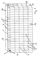
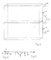
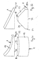
- the wire basket 1 shown in FIGS. 1 and 2 is used as a stem for Walls, in particular building walls, retaining walls, parapets, skeletal structures or similar walls. Several such Wire baskets 1 are placed next to and / or one above the other in front of a wall 2 (Fig. 14) arranged.
- the cuboid wire baskets 1 are in a known manner from in assembled position vertical and horizontal bars 3 made to 8, which cross each other and at the crossing points are welded together.
- the free ends 9 to 14 of the bars are loop-shaped in a known manner.
- the Wire baskets 1 consist of a front wall 15, a rear wall 16, Side walls 24, 25, a bottom 22 and a lid 17, the from the bars 3, 4 and 5, 6 and 7, 8 are formed.
- the walls and the cover 17 are via rod-like connecting parts 18, 19 and 20 (Fig. 20, 22, 23) connected to each other by the aligned loop-shaped ends 9 to 14 are inserted, such as is still described.
- the wire baskets 1 are in fastening parts 21 hung, which are attached to the wall 2.
- the wire baskets 1 are on the construction site with natural or artificial stones or some other suitable material. After closing the lid 17, the filled wire baskets 1 in the fasteners 21 hung.
- the wire baskets and are advantageous your fasteners made of stainless steel, galvanized steel, plastic-coated galvanized steel or combinations of these materials.
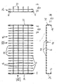
- the front grille 15 has an L-shape in side view a lower short leg 22, which by bending the lower End portions 23 of the undeformed front grille 15 is formed and forms the bottom of the wire basket 1.
- the front grille 15 consists of a large number of the same distance next to each other Longitudinal bars 3 and perpendicular to these transverse bars 4, which are also the same, but have a greater distance from each other than the longitudinal rods 3.
- the end portions 23 are through the over lower crossbar 4 projecting longitudinal bar sections formed.
- the Longitudinal and transverse bars 3, 4 can also have the same distance from one another from each other.
- the ends of all rods 3, 4 are closed the loops 9, 10 shaped.
- the rear wall 16 has a U-shape in plan view. It is like the front wall 15 through a flat grid with the longitudinal bars 5 and the cross bars 6 are formed. The distance of the longitudinal and Cross bars 5 and 6 from each other correspond to that of the longitudinal bars 3 and 4 of the front wall 15.
- the wall 16 is, as FIG. 8 shows, on its Narrow sides to form the side walls 24 and 25 at right angles bent. The end sections are off to form the side walls the penultimate vertical rod 5 bent on both sides. The ends 11, 12 of all wire rods 5, 6 are shaped into loops.
- the lid 17 according to FIGS. 11 and 12 of the mesh basket 1 is made exemplary from a longitudinal rod 7 and parallel with a greater distance juxtaposed cross bars 8.
- the ends 13, 14 of the Wire rods 7, 8 are shaped into loops.
- the different walls and the lid 17 are each made flat wire mesh. These items can already pre-assembled to complete baskets by the manufacturer, whereby only the lid 17 remains open and on site after filling the wire basket 1 is closed.
- the loop shown in FIG. 23 shown corner connector 20 inserted. This consists of one straight round rod with a hook-shaped bent end 26.
- the corner connector 20 is from below in the direction of arrow P in Fig. 2 through the aligned loops 10, 12 and through the lower loop of the side walls 24 and 25 inserted. At both Such a corner connector 20 becomes the side edges of the front grille 15 intended.
- the connecting part 19 (Fig. 22) is then inserted. It exists from a round wire, the ends 29 and 30 bent into a hook are. Then the hook-shaped ends 29, 30 of the Connecting part 19 suspended in the legs 27 of the corner connector 20.
- the lid is used to fasten the lid 17 to the front grille 15 with the loop-shaped ends 14 of its cross bars 8 to the upper Loops 9 of the longitudinal bars 3 of the front grille 15 created.
- a further connecting part 18 (Fig. 20 and 21) inserted that as a one-sided angled round rod is trained. It is inserted so far through the loops 9, 14 until with the angled end 31 into one of the side walls 24, 25 of the rear wall 16 can be threaded. After that, the end 32 bent at right angles (see Fig. 20).
- the connecting part 18 serves as a pivot axis for the cover 17. To secure it in the closed position, use the aligned loops 14 of the cross bars 8 of the cover 17 and the loops 9 at the upper edge of the rear wall 16 further connecting part 19 inserted after filling.
- spacers 47 (Fig. 2, 24) is provided. They consist of a round rod, the Ends 48, 49 in the assembled position hook-shaped inwards towards are bent towards each other.
- the spacers are preferably 47 arranged in the vertical and vertical direction of the wire basket 1. You can hang anywhere in the walls 15, 16 become.
- the spacers 47 encompass the ends 48, 49 of the Bars 3, 4 and 5, 6 at their crossing points.
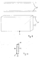
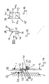
- the filled wire basket 1 is connected to the connecting parts 37 in the Wall 2 attached fasteners 21 hooked. They are equal educated.
- the fastening parts 21 are hanging rails with a flat, against the wall 2 abutting part 33, the lower Longitudinal edge 34 is bent like a hook.
- the system part 33 has Distance from each other in the longitudinal direction of the plant part 33 extending elongated holes 35 (FIG. 19) through the fastening parts, such as screws or the like, can be inserted. Over the slots 35 can achieve an optimal alignment with respect to the wall 2 become.
- There is at least one in the curved longitudinal edge 34 one, preferably several, spaced openings 36, through the water penetrating into the suspension rail 21 or the like can flow off.
- the spacer and suspension parts 47, 21, 37 can also be made of plastic consist.
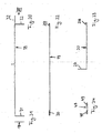
- the hanging rail 21 can also be designed so that its lower Longitudinal edge 34 'is U-shaped (Fig. 18).
- the plant part 33 ' has the elongated holes 35' and the U-shaped longitudinal edge 34 'at least a drain opening 36 '.
- the lower longitudinal edge of the rail 34 ' can also V-shaped with a lower drain opening 36 '.
- FIG. 18b shows a rail 34 'with a Z-shaped profile. she has a shorter leg 34 ', the cross bar 50 in a longer Leg 33 'merges, which forms the plant part. This has the openings or elongated holes 35 ', while the drain openings 36' in Transition area from the crosspiece 50 into the shorter leg 34 ' are provided.
- the rail 21 ' accordinging to Fig. 18c consists of the part 33', which as a flat Rail is formed, the elongated holes in one half 35 '. At the attachment points 35 'is a spacer used and the necessary wall clearance is set.
- All suspension parts 21, 21 ' can of course also as Individual suspension to be designed, for example, at an angle Buildings to be used at the transition to a slope.
- the wire baskets 1 instead of the two rails (Fig. 9 and 10) each have at least two suspension parts 21, 21 'at a distance provided side by side.
- the connecting parts 37 are on the rear wall 16 of the Wire basket 1 provided. So two rows of connectors can 37 may be provided, each row being at least two at a distance has adjacent connection parts 37.
- the connecting part 37 is of an approximately S-shaped bent sheet formed.
- the upper curved one in FIG. 14 End 38 is slightly lower than the lower curved end 39.
- Im free, upstanding leg 40 of the end 39 is a Push-through opening 40 'for a securing part 41, such as a screw (Fig. 14) provided.
- the connector 37 is at its end 39th suspended from below in one of the transverse wires 6 of the rear wall 16.
- the securing part 41 is then passed through the opening 40 used that it overlaps the cross wire 6.
- the connector 37 is thereby held captive on the wire basket 1.
- a stabilizing rod on the web 43 connecting the ends 38 and 39 44 attached To the connector 37 in its upright position relative to the rear wall 16, is a stabilizing rod on the web 43 connecting the ends 38 and 39 44 attached. It lies in the assembled position Fig. 14 slightly below the free edge 45 of the end 38 and protrudes on both sides via the connecting part 37. With the protruding rod ends 44a, 44b, the connecting part 37 is located on adjacent longitudinal bars 5 of the rear wall 16, so that a tilt-proof position is guaranteed is.
- the connecting part 37 lies with its web 43 within a mesh opening of the rear wall grille 16.
- the stabilizing bar 44 lies within the wire basket 1.
- the upper, curved end 38 protrudes backwards over the rear wall 16. With this end 38 that becomes Connection part 37 hooked into the fastening part 21. Since the attachment and the connecting part 21, 37 consist of flat material, extensive support is guaranteed. Because advantageously two Connection parts 37 are provided in each row, the wire basket 1 can be hung
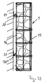
- FIGS. 9 and 10 are for fastening the wire baskets 1st two suspension parts 21 arranged one above the other at a distance intended.
- the upper and lower suspension rails 21 serve for load absorption and transfer to the wall 2, the lower one Rail 21 also serves as a spacer and ensures that the wire basket 1 will not be unintentionally posted or can be lifted off the wall by wind suction.
- two wire baskets 1 are provided, which are each suspended in two suspension rails 21.
- the wire baskets 1 can be arranged one above the other and / or next to one another be to the walls 2 to the extent required or to partially cover.
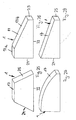
- baskets 1 can also be narrow and in special shapes 25 to 32 may be formed.
- 25 has the wire basket 1 in the side view the shape of an essentially isosceles Trapezes with a flat floor and a parallel cover and inclined side walls 24, 25.
- 26 has the bottom 22 and perpendicular to it Side walls 24, 25, of which one side wall 24 around is several times longer than the side wall 25.
- the basket 1 according to FIG. 27 largely corresponds to that according to FIG. 26.
- the cover 17 is curved outward in the form of a part circle.
- the basket 1 according to FIG. 29 corresponds to that according to FIG. 27; however he has a part-circular inward, towards the bottom 22 curved Lid 17.
- Fig. 30 shows a basket 1, the shape of a side view right triangle.
- the basket 1 has a rectangular shape with a partial circular shape outward or inward curved rear or front wall 16 or 15.
- the side walls 24, 25 are inclined accordingly.
- FIG. 32 shows a basket 1 which is similar to that of FIG. 25. however the lid 17 is shorter and the side walls 24 and 25 are short Sidewall sections 24a perpendicular to the bottom 22 and 25a.
- the wire baskets 1 can be pre-wire baskets fill it up while it is fastened to the floor with the filling material.
- the wire baskets 1 can then simply and when filled can be hooked into the suspension rails 21 without difficulty.
- the wire baskets 1 can be attached to the wall in such a way that they are arranged one above the other and side by side without gaps can.
- the hanging rails it is of course possible that several on the rails Wire baskets 1 can be arranged side by side.
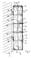
- Fig. 33 shows a further embodiment of a stem Mesh basket 1.
- this lattice basket essentially in that the Front wall 15 in the horizontal section U-shape and in the vertical section L-shape and that the rear wall 16 is formed as a simple flat grid is. Furthermore, there is no lid in the mesh basket according to FIG. 33 intended. Otherwise, the front and rear walls 15, 16 are essentially the same design as that of FIG. 1 crossing with each other Longitudinal and cross bars 3, 4 and 5, 6.
- the side walls 24 and 25 of the mesh basket 1 are through the U-legs and the basket bottom 22 through the L-leg of the formed as a molded part Front wall 15 formed.
- the side walls 24, 25 and the bottom 22 are formed in one piece with the end face 15 'of the front grille 15.
- the bottom 22 is by bending the lower parts of the longitudinal bars 3rd the front 15 'formed.
- the free ends 9 of the longitudinal bars 3 are like the ends 9 of the bottom 22 according to FIG. 3 like a loop or curved like a loop.
- the longitudinal bars 3 of the front side 15 ' close at the upper edge flush with the upper horizontal cross wire 4 '. This has the Advantage that at the front of the basket 1 no sharp Edges or protrusions are provided during handling of the mesh basket 1 could lead to injuries.
- Part of the vertical wires or rods 3, for example four of these wires, the Front wall 15 is at the upper end above the upper horizontal Cross wire 4 'bent backwards at right angles (FIGS. 34, 36).
- the free Ends 9 'of these wires 3 are like the ends 12 of the side walls 24, 25 U-shaped. They serve as hooks for the upper one horizontal cross wire 6 of the rear wall 16. Since only part of the Vertical wires 3 is bent at the top, are attached to this Narrow side of the mesh basket 1 large filling openings formed.
- FIG. 40, 41 On the rear wall 16 there are several spacers 47 (FIGS. 40, 41) attached at a right-angled end 48, preferably welded so that they protrude vertically over the wall surface (Fig. 38, 39). Its other ends 49 are bent in a U-shape. The end 49 is rotated by approximately 45 ° with respect to the end 48 (cf. FIG. 40c). Due to the rigid connection of the spacers 47 to the cross bars 6 of the rear wall 16, the spacers 47 are immovable on the Back wall secured. In the assembled position, the hook ends are 49 in Adjacent cross bars 4 of the front grille 15 are suspended. The hook-shaped Ends 49 encompass the bars 4 at the crossing points their transverse and longitudinal wires 3, 4, which is twisted by the Training of the ends 49 is reached.
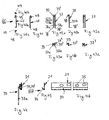
- connection parts 37, 37 ' (FIGS. 42a to 42c or 43a to 43c) for hanging in the mesh baskets 1 into the fastening parts 21 provided on the wall (FIGS. 44 to 46) attached to the rear wall 16, preferably welded.
- she are formed by a hairpin or U-shaped wire, which has two mutually parallel legs 37a, 37b. You are close their free ends 38, 38 'and near the hooks on cross wires 6 of the rear wall 16 welded.
- the arched one inside the other Transcending ends 39, 39 'of the connecting parts 37, 37' are hook-shaped bent outwards and form the hook, with which the connector is hooked into the holder 21. He is like that previously described embodiments as a rail with slot openings 35 and a curved longitudinal edge 34 formed in which the connecting part 37, 37 'hooked with its hook end 39, 39' 44 to 46).
- the legs 37a, 37b of the connecting parts 37 are relatively long, while the connecting parts 37 '(Fig. 43a to 43c) essential are shorter. Since the longer connecting parts 37 on two cross wires 6 are attached, they are securely held on the rear wall 16 and cannot inadvertently under the load of the existing in the mesh basket 1 Stones or the like can be demolished.
- the short ones Connecting parts 37 ' secure the basket 1 in its hanging on the wall Position if, for example, wind forces are acting on the basket. Without the securing via the connecting parts 37 ', the grid baskets would 1 under the wind force away from the wall and upwards pivoted so that the baskets themselves and their contents no longer would be properly secured.
- the mesh basket 1 On the top or filling side of the mesh basket 1 are due to the described Training no grid parts narrowing the cross section provided so that the mesh basket can be easily filled. There the mesh basket 1 has no lid on the filling side, and thereby is open at the top, it can be opened up to the upper rim of the basket fill completely. The stones can even go over the top of the basket 1 protrude, without thereby putting on the next Mesh basket 1 is impaired. This way is a gapless Stem 1 can be filled with stones.
- connection parts 37, 37 ' there are two upper ones on the rear wall 16 and two lower connecting parts 37, 37 'are provided.
- the lower, shorter ones Connection parts 37 ' are each aligned in height with the upper connecting parts 37.
- the free ends 48 are there at the corresponding ones Cross bars 6 welded. It can be beneficial instead of the two upper suspension parts 37 three with preferably the same Provide spacing between the hanging parts.
Landscapes
- Engineering & Computer Science (AREA)
- Architecture (AREA)
- Structural Engineering (AREA)
- Civil Engineering (AREA)
- Mining & Mineral Resources (AREA)
- Paleontology (AREA)
- General Life Sciences & Earth Sciences (AREA)
- General Engineering & Computer Science (AREA)
- Life Sciences & Earth Sciences (AREA)
- Environmental & Geological Engineering (AREA)
- Chemical & Material Sciences (AREA)
- Ceramic Engineering (AREA)
- Finishing Walls (AREA)
- Panels For Use In Building Construction (AREA)
- Fencing (AREA)
- Pit Excavations, Shoring, Fill Or Stabilisation Of Slopes (AREA)
- Load-Bearing And Curtain Walls (AREA)
Abstract
Description
Die Erfindung betrifft einen Vorbau für Wände, wie Gebäudewände,
Stützwände, Brüstungen, Stahlkonstruktionen und dergleichen nach
dem Oberbegriff des Anspruches 1.The invention relates to a stem for walls, such as building walls,
Retaining walls, parapets, steel structures and the like
the preamble of
Es ist bekannt, als Vorbau für Wände mehrere, zum Beispiel mit Natursteinen, Kunststeinen, Glaskörpern und anderem Füllmaterial gefüllte Drahtkörbe über- und nebeneinander anzuordnen. Solche Drahtkörbe sind auf dem Untergrund abgestützt und am Gebäude über Schrauben oder dergleichen gesichert und müssen an der Wand selbst gefüllt werden. Da hierbei die gesamte Last des Vorbaues von diesem selbst getragen werden muß, müssen die Drahtkörbe relativ breit sein. Infolge der bodenseitigen Abstützung können die Drahtkörbe nur dort eingesetzt werden, wo der Vorbau bis zum Untergrund reicht, in den die hohe Last der Körbe eingeleitet wird.It is known to use several, for example natural stone, Filled with artificial stones, vitreous bodies and other filling material Arrange wire baskets on top of and next to each other. Such Wire baskets are supported on the ground and on the building secured by screws or the like and must be on the wall be filled yourself. Since the entire load of the stem of this must be carried itself, the wire baskets must be relative be wide. As a result of the base support, the wire baskets can only be used where the stem to the ground enough, into which the high load of the baskets is introduced.
Der Erfindung liegt die Aufgabe zugrunde, einen Vorbau dieser Art so auszubilden, daß Einzelelemente problemlos auch am Boden stehend befüllt und dann einfach an einer Wand aufgehängt und gesichert werden können.The invention has for its object a stem of this type train that individual elements standing on the floor without problems filled and then simply hung on a wall and secured can be.
Diese Aufgabe wird bei einem Vorbau der gattungsbildenden Art erfindungsgemäß
mit den kennzeichnenden Merkmalen des Anspruches
1 gelöst. This object is achieved according to the invention in a stem of the generic type
with the characterizing features of the
Bei dem erfindungsgemäßen Vorbau kann das Lastaufnahmeteil oberhalb des Bodens am Gebäude vorgesehen und mit dem Halter verbunden werden. Dieser ist am Vorbau so vorgesehen, daß er nicht in den zu befüllenden Raum des Vorbaues ragt. Dadurch kann der Vorbau vor seiner Montage an einer Gebäudewand problemlos mit dem Füllmaterial befüllt werden, ohne daß das Lastaufnahmeteil den Befüllvorgang behindern kann. Die Last der Einzelelemente wird von der Wand aufgenommen. Die Einzelelemente können dadurch sehr schmal ausgebildet sein.In the stem according to the invention, the load-bearing part provided above the floor on the building and with the holder get connected. This is provided on the stem so that it does not protrudes into the space to be filled in the stem. This allows the Stem without problems before installing it on a building wall the filling material are filled without the load-bearing part Filling can hinder. The load of the individual elements is determined by the wall. The individual elements can be very be narrow.
Weitere Merkmale der Erfindung ergeben sich aus den weiteren Ansprüchen, der Beschreibung und den Zeichnungen.Further features of the invention result from the further claims, the description and the drawings.
Die Erfindung wird nachstehend anhand eines in den Zeichnungen dargestellten Ausführungsbeispieles näher beschrieben. Es zeigen
- Fig. 1
- in schematischer und perspektivischer Darstellung einen erfindungsgemäßen Vorbau,
- Fig. 2
- den Vorbau gemäß Fig. 1 in Ansicht gemäß Pfeil II in Fig. 1,
- Fig. 3
- ein Frontgitter des Vorbaues gemäß Fig. 2 in Seitenansicht und in verkleinerter Darstellung,
- Fig. 4
- das Gitter nach Fig. 3 in Draufsicht,
- Fig. 5
- das Gitter nach Fig. 4 in Ansicht gemäß Pfeil V in Fig. 4,
- Fig. 6
- ein Rückwandgitter des Vorbaues gemäß Fig. 1 bzw. 2 in Draufsicht und in verkleinerter Darstellung,
- Fig. 7 und 8
- das Gitter nach Fig. 6 in Ansicht gemäß Pfeil VII bzw. VIII in Fig. 6,
- Fig. 9 und 10
- in schematischer Darstellung die Befestigung des Vorbaues,
- Fig. 11
- einen Deckel des Vorbaues gemäß Fig. 1 bzw. 2 in Seitenansicht und verkleinerter Darstellung,
- Fig. 12
- eine Ansicht gemäß Pfeil XII in Fig. 11,
- Fig. 13
- in schematischer und verkleinerter Darstellung und in Seitenansicht den Vorbau gemäß Fig. 2,
- Fig. 14
- einen Teil der Rückwand des Vorbaues gemäß Fig. 1 bzw. 2 mit einem Anschlußteil und einem Befestigungsteil in Seitenansicht,
- Fig. 15
- das Anschlußteil nach Fig. 14 in Seitenansicht,
- Fig. 16
- das Anschlußteil nach Fig. 15 in Ansicht gemäß Pfeil XVI,
- Fig. 17
- das Befestigungsteil nach Fig. 14 in Seitenansicht,
- Fig. 18, 18a bis 18c
- jeweils eine weitere Ausführungsform des Befestigungsteiles in einer Ansicht gemäß Fig. 17,
- Fig. 19
- das Befestigungsteil gemäß Fig. 14 in Ansicht gemäß Pfeil XIX in Fig. 17,
- Fig. 20
- ein Verbindungsteil des Vorbaues gemäß Fig. 2 in Seitenansicht,
- Fig. 21
- das Verbindungsteil nach Fig. 20 in Ansicht gemäß Pfeil XXI,
- Fig. 22
- ein weiteres Verbindungsteil des Vorbaues nach Fig. 2 in Seitenansicht,
- Fig. 23
- einen Eckverbinder des Vorbaues gemäß Fig. 2 in Seitenansicht,
- Fig. 24
- ein Distanzteil des Vorbaues gemäß Fig. 2,
- Fig.25 bis 32
- jeweils in schematischer Darstellung weitere Ausführungsformen von erfindungsgemäßen Vorbauten,
- Fig. 33
- eine weitere Ausführungsform eines erfindungsgemäßen Vorbaus in einer Ansicht gemäß Fig. 2,
- Fig. 34
- das Frontgitter des Vorbaus nach Fig. 33 in Stirnansicht gemäß Pfeil XXXIV in Fig. 35,
- Fig. 35
- das Gitter nach Fig. 34 in Seitenansicht gemäß Pfeil XXXV in Fig. 34,
- Fig. 36
- das Gitter nach Fig. 34 in Draufsicht gemäß Pfeil XXXVI in Fig. 34,
- Fig. 37
- ein Rückwandgitter des Vorbaus nach Fig. 33 in Stirnansicht und in verkleinerter Darstellung,
- Fig. 38
- das Rückwandgitter nach Fig. 37 in Ansicht gemäß Pfeil XXXVIII in Fig. 37,
- Fig. 39
- das Gitter nach Fig. 37 in Draufsicht gemäß Pfeil XXXIX in Fig. 37,
- Fig. 40a
- ein Distanzteil des Vorbaues nach Fig. 33 in Seitenansicht,
- Fig. 40b und 40c
- das Distanzteil nach Fig. 40a in Draufsicht bzw. in Unteransicht,
- Fig. 41
- das Distanzteil nach Fig. 40a in Ansicht gemäß Pfeil XLI in Fig. 40a
- Fig. 42a
- ein Anschlußteil des Vorbaus nach Fig. 33 in Vorderansicht,
- Fig. 42b und 42c
- das Anschlußteil nach Fig. 41 a in Seiten- bzw. Rückansicht
- Fig. 43a und 43c
- eine weitere Ausführungsform eines Anschlußteiles in Darstellungen entsprechend den Fig. 42a bis 42c,
- Fig. 44
- das Anschlußteil gemäß den Fig. 42a bis 42c, das in ein Befestigungsteil eingehängt ist, in Seitenansicht,
- Fig. 45
- das Befestigungsteil nach Fig. 43 in Seitenansicht,
- Fig. 46
- das Befestigungsteil nach Fig. 44 in Ansicht gemäß Pfeil XLVI,
- Fig. 47
- in schematischer Darstellung die Befestigung des Vorbaues gemäß Fig. 33 mit weiteren entsprechenden Vorbauten,
- Fig. 48
- die Einzelheit A in Fig. 47 in Draufsicht.
- Fig. 1
- a schematic and perspective representation of a stem according to the invention,
- Fig. 2
- 1 in view according to arrow II in Fig. 1,
- Fig. 3
- 3 shows a front grille of the stem according to FIG. 2 in a side view and in a reduced representation,
- Fig. 4
- 3 in top view,
- Fig. 5
- 4 in a view according to arrow V in FIG. 4,
- Fig. 6
- 1 and 2 in plan view and in a reduced view,
- 7 and 8
- 6 in a view according to arrow VII or VIII in FIG. 6,
- 9 and 10
- the attachment of the stem in a schematic representation,
- Fig. 11
- 1 in a side view and a reduced view,
- Fig. 12
- 11 shows a view according to arrow XII in FIG. 11,
- Fig. 13
- in a schematic and reduced representation and in side view the stem according to FIG. 2,
- Fig. 14
- 1 and 2 with a connecting part and a fastening part in side view,
- Fig. 15
- 14 in side view,
- Fig. 16
- 15 in the view according to arrow XVI,
- Fig. 17
- 14 in side view,
- 18, 18a to 18c
- in each case a further embodiment of the fastening part in a view according to FIG. 17,
- Fig. 19
- 14 in the view according to arrow XIX in FIG. 17,
- Fig. 20
- 3 shows a connecting part of the stem according to FIG. 2 in side view,
- Fig. 21
- 20 in the view according to arrow XXI,
- Fig. 22
- another connecting part of the stem of FIG. 2 in side view,
- Fig. 23
- 3 shows a corner connector of the stem according to FIG. 2 in side view,
- Fig. 24
- a spacer of the stem according to FIG. 2,
- Fig. 25 to 32
- each in a schematic representation further embodiments of stems according to the invention,
- Fig. 33
- 2 shows another embodiment of a stem according to the invention in a view according to FIG. 2,
- Fig. 34
- 33 in front view according to arrow XXXIV in Fig. 35,
- Fig. 35
- 34 in side view according to arrow XXXV in FIG. 34,
- Fig. 36
- 34 in top view according to arrow XXXVI in FIG. 34,
- Fig. 37
- 33 in front view and in a reduced representation,
- Fig. 38
- 37 in view according to arrow XXXVIII in FIG. 37,
- Fig. 39
- 37 in top view according to arrow XXXIX in FIG. 37,
- Fig. 40a
- 33 shows a spacer part of the stem according to FIG. 33 in a side view,
- 40b and 40c
- 40a in top view or in bottom view,
- Fig. 41
- 40a in the view according to arrow XLI in FIG. 40a
- Fig. 42a
- 33 shows a connection part of the stem according to FIG. 33 in front view,
- 42b and 42c
- the connector according to Fig. 41 a in side or rear view
- 43a and 43c
- another embodiment of a connecting part in representations corresponding to FIGS. 42a to 42c,
- Fig. 44
- 42a to 42c, which is suspended in a fastening part, in side view,
- Fig. 45
- 43 in side view,
- Fig. 46
- 44 in the view according to arrow XLVI,
- Fig. 47
- 33 shows a schematic representation of the attachment of the stem according to FIG. 33 with further corresponding stems,
- Fig. 48
- the detail A in Fig. 47 in plan view.
Der in den Fig. 1 und 2 dargestellte Drahtkorb 1 wird als Vorbau für
Wände, insbesondere Gebäudewände, Stützwände, Brüstungen, Skelettkonstruktionen
oder ähnliche Wände verwendet. Mehrere solcher
Drahtkörbe 1 werden neben- und/oder übereinander vor einer Wand 2
(Fig. 14) angeordnet.The
Die quaderförmigen Drahtkörbe 1 sind in bekannter Weise aus in
montierter Lage vertikal und horizontal verlaufenden Gitterstäben 3
bis 8 hergestellt, die einander kreuzen und an den Kreuzungspunkten
miteinander verschweißt sind. Die freien Enden 9 bis 14 der Gitterstäbe
sind in bekannter Weise schlaufenförmig ausgebildet. Die
Drahtkörbe 1 bestehen aus einer Frontwand 15, einer Rückwand 16,
Seitenwänden 24, 25, einem Boden 22 sowie einem Deckel 17, die
aus den Gitterstäben 3, 4 bzw. 5, 6 und 7, 8 gebildet sind. Die Wände
sowie der Deckel 17 sind über stabartige Verbindungsteile 18, 19 und
20 (Fig. 20, 22, 23) miteinander verbunden, die durch die miteinander
fluchtenden schlaufenförmigen Enden 9 bis 14 gesteckt werden, wie
noch beschrieben wird.The
In montierter Lage gemäß Fig. 9 und 10 sind die Drahtkörbe 1 in Befestigungsteile
21 eingehängt, die an der Wand 2 befestigt werden.
Die Drahtkörbe 1 werden auf der Baustelle mit Natur- oder Kunststeinen
oder einem anderen geeigneten Material gefüllt. Nach Schließen
des Deckels 17 werden die gefüllten Drahtkörbe 1 in die Befestigungsteile
21 eingehängt. Vorteilhaft bestehen die Drahtkörbe und
ihre Befestigungsteile aus Edelstahl, verzinktem Stahl, kunststoffbeschichtetem
verzinktem Stahl oder auch Kombinationen dieser Werkstoffmaterialien.9 and 10, the
Wie Fig. 3 zeigt, hat das Frontgitter 15 in Seitenansicht L-Form mit
einem unteren kurzen Schenkel 22, der durch Umbiegen der unteren
Endabschnitte 23 des unverformten Frontgitters 15 gebildet ist und
den Boden des Drahtkorbes 1 bildet. Das Frontgitter 15 besteht aus
einer Vielzahl von mit gleichem Abstand nebeneinander liegenden
Längsstäben 3 und senkrecht zu diesen verlaufenden Querstäben 4,
die ebenfalls gleichen, jedoch größeren Abstand voneinander haben
als die Längsstäbe 3. Die Endabschnitte 23 sind durch die über den
unteren Querstab 4 ragenden Längsstababschnitte gebildet. Die
Längs- und Querstäbe 3, 4 können untereinander auch gleichen Abstand
voneinander haben. Die Enden sämtlicher Stäbe 3, 4 sind zu
den Schlaufen 9, 10 geformt.3, the
Die Rückwand 16 gemäß den Fig. 6 bis 8 hat in Draufsicht U-Form.
Sie ist wie die Frontwand 15 durch ein ebenes Gitter mit den Längsstäben
5 und den Querstäben 6 gebildet. Der Abstand der Längs- und
Querstäbe 5 bzw. 6 voneinander entspricht dem der Längsstäbe 3
und 4 der Frontwand 15. Die Wand 16 ist, wie Fig. 8 zeigt, an ihren
Schmalseiten zur Bildung der Seitenwände 24 und 25 rechtwinklig
umgebogen. Zur Bildung der Seitenwände sind die Endabschnitte ab
dem vorletzten Vertikalstab 5 an beiden Seiten abgebogen. Die Enden
11, 12 sämtlicher Drahtstäbe 5, 6 sind zu Schlaufen geformt.The
Der Deckel 17 gemäß den Fig. 11 und 12 des Gitterkorbes 1 besteht
beispielhaft aus einem Längsstab 7 und mit größerem Abstand parallel
nebeneinander angeordneten Querstäben 8. Die Enden 13, 14 der
Drahtstäbe 7, 8 sind zu Schlaufen geformt.The
Die verschiedenen Wände und der Deckel 17 werden jeweils aus
ebenen Drahtgittern hergestellt. Diese Einzelteile können bereits
beim Hersteller zu kompletten Körben vormontiert werden, wobei nur
der Deckel 17 offen bleibt und auf der Baustelle nach dem Befüllen
der Drahtkörbe 1 verschlossen wird. Um die Frontwand 15 mit der
Rückwand 16 zu verbinden, werden diese so angeordnet, daß die
Schlaufen 9, 10, 11, 12 unmittelbar benachbart zueinander liegen.
Durch die miteinander fluchtenden Schlaufen 10, 12 wird der in Fig.
23 dargestellte Eckverbinder 20 gesteckt. Dieser besteht aus einem
geraden Rundstab mit einem hakenförmig umgebogenen Ende 26.
Der Eckverbinder 20 wird von unten in Richtung des Pfeiles P in Fig.
2 durch die miteinander fluchtenden Schlaufen 10, 12 und durch die
untere Schlaufe der Seitenwände 24 bzw. 25 gesteckt. An beiden
Seitenrändern des Frontgitters 15 wird ein solcher Eckverbinder 20
vorgesehen.The different walls and the
Durch die Schlaufen 9 und 11 des Frontgitters 15 und der Rückwand
16 wird dann das Verbindungsteil 19 (Fig. 22) gesteckt. Es besteht
aus einem Runddraht, dessen Enden 29 und 30 hakenförmig umgebogen
sind. Danach werden die hakenförmigen Enden 29, 30 des
Verbindungsteiles 19 in die Schenkel 27 der Eckverbinder 20 eingehängt.Through the
Zur Befestigung des Deckels 17 am Frontgitter 15 wird der Deckel
mit den schlaufenförmigen Enden 14 seiner Querstäbe 8 an die oberen
Schlaufen 9 der Längsstäbe 3 des Frontgitters 15 angelegt.
Durch diese Schlaufen 9, 14 wird dann ein weiteres Verbindungsteil
18 (Fig. 20 und 21) gesteckt, das als einseitig gewinkelter Rundstab
ausgebildet ist. Er wird so weit durch die Schlaufen 9, 14 gesteckt,
bis er mit dem abgewinkelten Ende 31 in eine der Seitenwände 24,
25 der Rückwand 16 eingefädelt werden kann. Danach wird das Ende
32 rechtwinklig abgebogen (vgl. Fig. 20). Wie sich aus Fig. 2 ergibt,
liegen die Enden 31, 32 in dieser Lage parallel zu den Querstäben 8
des Deckels 17. Das Verbindungsteil 18 dient als Schwenkachse für
den Deckel 17. Um ihn in der Schließstellung zu sichern, wird durch
die miteinander fluchtenden Schlaufen 14 der Querstäbe 8 des Dekkels
17 und den Schlaufen 9 am oberen Rand der Rückwand 16 ein
weiteres Verbindungsteil 19 nach dem Befüllen gesteckt.The lid is used to fasten the
Um zu verhindern, daß sich die Front- und die Rückwand 15, 16 beim
Befüllen des Drahtkorbes 1 nach außen wölben, sind Distanzhalter
47 (Fig. 2, 24) vorgesehen. Sie bestehen aus einem Rundstab, dessen
Enden 48, 49 in montierter Lage hakenförmig nach innen in Richtung
zueinander gebogen sind. Vorzugsweise sind die Distanzhalter
47 in Höhen- und Breitenrichtung des Drahtkorbes 1 verteilt angeordnet.
Sie können an beliebiger Stelle in die Wände 15, 16 eingehängt
werden. Die Distanzhalter 47 umgreifen mit ihren Enden 48, 49 die
Gitterstäbe 3, 4 und 5, 6 an ihren Kreuzungspunkten.To prevent the front and
Der befüllte Drahtkorb 1 wird mit den Anschlußteilen 37 in die an der
Wand 2 befestigten Befestigungsteile 21 eingehängt. Sie sind gleich
ausgebildet. Die Befestigungsteile 21 sind Einhängeschienen mit einem
ebenen, an der Wand 2 anliegenden Anlageteil 33, dessen unterer
Längsrand 34 hakenförmig gebogen ist. Der Anlageteil 33 hat mit
Abstand voneinander liegende, in Längsrichtung des Anlageteiles 33
sich erstreckende Langlöcher 35 (Fig. 19), durch die Befestigungsteile,
wie Schrauben oder dgl., gesteckt werden können. Über die Langlöcher
35 kann eine optimale Ausrichtung gegenüber der Wand 2 erreicht
werden. Im gebogenen Längsrand 34 befindet sich mindestens
eine, vorzugsweise mehrere mit Abstand voneinander liegende Öffnungen
36, durch die in die Einhängeschiene 21 eindringendes Wasser
oder dgl. abfließen kann.The filled
Die Distanz- und Aufhängeteile 47, 21, 37 können auch aus Kunststoff
bestehen.The spacer and
Die Einhängeschiene 21 kann auch so ausgebildet sein, daß ihr unterer
Längsrand 34' U-förmig ausgebildet ist (Fig. 18). Der Anlageteil
33' hat die Langlöcher 35' und der U-förmige Längsrand 34' mindestens
eine Ablauföffnung 36'.The hanging
Wie Fig. 18a zeigt, kann der untere Längsrand der Schiene 34' auch V-förmig mit einer unteren Ablauföffnung 36' ausgebildet sein.18a shows, the lower longitudinal edge of the rail 34 'can also V-shaped with a lower drain opening 36 '.
Fig. 18b zeigt eine Schiene 34' mit Z-förmigem Profil. Sie hat einen
kürzeren Schenkel 34', der über einen Quersteg 50 in einen längeren
Schenkel 33' übergeht, der das Anlageteil bildet. Dieses hat die Öffnungen
bzw. Langlöcher 35', während die Ablauföffnungen 36' im
Übergangsbereich vom Quersteg 50 in den kürzeren Schenkel 34'
vorgesehen sind.18b shows a rail 34 'with a Z-shaped profile. she has a
shorter leg 34 ', the
Die Schiene 21' nach Fig. 18c besteht aus dem Teil 33', das als flache Schiene ausgebildet ist, die in ihrer einen Hälfte die Langlöcher 35' aufweist. An den Befestigungsstellen 35' wird ein Distanzstück eingesetzt und damit wird der notwendige Wandabstand eingestellt.The rail 21 'according to Fig. 18c consists of the part 33', which as a flat Rail is formed, the elongated holes in one half 35 '. At the attachment points 35 'is a spacer used and the necessary wall clearance is set.
Sämtliche Einhängeteile 21, 21' können selbstverständlich auch als
Einzelaufhängung ausgebildet sein, um beispielsweise bei schrägen
Bauten am Übergang zu einer Schräge eingesetzt zu werden. In
diesem Fall sind für die Drahtkörbe 1 anstelle der beiden Schienen
(Fig. 9 und 10) jeweils wenigstens zwei Einhängeteile 21, 21' mit Abstand
nebeneinander vorgesehen.All
Die Anschlußteile 37 (Fig. 15 und 16) sind an der Rückwand 16 des
Drahtkorbes 1 vorgesehen. So können zwei Reihen von Anschlußteilen
37 vorgesehen sein, wobei jede Reihe wenigstens zwei mit Abstand
nebeneinander liegende Anschlußteile 37 aufweist. Wie die
Fig. 14 bis 16 zeigen, ist das Anschlußteil 37 aus einem etwa S-förmig
gebogenen Blech gebildet. Das in Fig. 14 obere gekrümmte
Ende 38 ist etwas niedriger als das untere gekrümmte Ende 39. Im
freien, nach oben ragenden Schenkel 40 des Endes 39 ist eine
Durchstecköffnung 40' für ein Sicherungsteil 41, wie eine Schraube
(Fig. 14), vorgesehen. Das Anschlußteil 37 wird mit seinem Ende 39
von unten in einen der Querdrähte 6 der Rückwand 16 eingehängt.
Anschließend wird das Sicherungsteil 41 so durch die Öffnung 40
eingesetzt, daß es den Querdraht 6 übergreift. Das Anschlußteil 37
ist dadurch unverlierbar am Drahtkorb 1 gehalten. Um das Anschlußteil
37 gegenüber der Rückwand 16 in seiner aufrechten Lage zu halten,
ist an dem die Enden 38 und 39 verbindenden Steg 43 ein Stabilisierungsstab
44 befestigt. Er liegt in der montierten Lage gemäß
Fig. 14 etwas unterhalb des freien Randes 45 des Endes 38 und ragt
beidseitig über das Anschlußteil 37. Mit den überstehenden Stabenden
44a, 44b liegt das Anschlußteil 37 an benachbarten Längsstäben
5 der Rückwand 16 an, so daß eine kippsichere Lage gewährleistet
ist. Das Anschlußteil 37 liegt mit seinem Steg 43 innerhalb einer Maschenöffnung
des Rückwandgitters 16. Der Stabilisierungsstab 44
liegt innerhalb des Drahtkorbes 1. Das obere, gekrümmte Ende 38
ragt nach hinten über die Rückwand 16. Mit diesem Ende 38 wird das
Anschlußteil 37 in das Befestigungsteil 21 eingehängt. Da das Befestigungs-
und das Anschlußteil 21, 37 aus Flachmaterial bestehen,
wird eine großflächige Abstützung gewährleistet. Da vorteilhaft zwei
Anschlußteile 37 in jeder Reihe vorgesehen sind, kann der Drahtkorb
1 einwandfrei aufgehängt werden. Die Last wird über die Befestigungsteile
21 auf die Wand übertragen.The connecting parts 37 (Fig. 15 and 16) are on the
Wie die Fig. 9 und 10 zeigen, sind zur Befestigung der Drahtkörbe 1
jeweils zwei mit Abstand übereinander angeordnete Einhängeteile 21
vorgesehen. Die oberen und unteren Einhängeschienen 21 dienen
zur Lastaufnahme und -übertragung an die Wand 2, wobei die untere
Schiene 21 außerdem als Abstandshalter dient und gewährleistet,
daß der Drahtkorb 1 nicht unbeabsichtigt ausgehängt werden oder
sich durch Windsogkräfte von der Wand abheben kann. As shown in FIGS. 9 and 10, are for fastening the wire baskets 1st
two
In Fig. 10 sind zwei aufeinander sitzende Drahtkörbe 1 vorgesehen,
die jeweils in zwei Einhängeschienen 21 eingehängt sind. Auf diese
Weise können die Drahtkörbe 1 über- und/oder nebeneinander angeordnet
werden, um die Wände 2 in gewünschtem Maße ganz oder
teilweise zu bedecken.10 two
Um auch schräge oder gerundete Wände 2 mit dem Vorbau zu versehen,
können die Körbe 1 auch schmal und in Sonderformen gemäß
den Fig. 25 bis 32 ausgebildet sein. Der Drahtkorb 1 nach Fig. 25 hat
in der Seitenansicht die Form eines im wesentlichen gleichschenkligen
Trapezes mit einem ebenen Boden, einem dazu parallelen Dekkel
und geneigten Seitenwänden 24, 25.In order to also provide sloping or
Der Korb 1 nach Fig. 26 hat den Boden 22 und senkrecht dazu verlaufende
Seitenwände 24, 25, von denen die eine Seitenwand 24 um
ein mehrfaches länger ist als die Seitenwand 25.26 has the bottom 22 and perpendicular to it
An die Seitenwand 24 schließt ein zum Boden 22 paralleler, relativ
kurzer Abschnitt 17a eines Deckels 17 an, der stumpfwinklig in einen
längeren Abschnitt 17b übergeht. Dieser liegt stumpfwinklig zur Seitenwand
25.At the
Der Korb 1 gemäß Fig. 27 entspricht weitgehend dem nach Fig. 26.
Der Deckel 17 ist jedoch teilkreisförmig nach außen gekrümmt.The
Auch der Korb nach Fig. 28 entspricht dem nach Fig. 26 mit dem Unterschied,
daß der Deckel 17 zwischen den Seitenwänden 24 und 25
gerade und schräg verläuft.28 also corresponds to that of FIG. 26 with the difference that
that the
Der Korb 1 gemäß Fig. 29 entspricht dem nach Fig. 27; er hat jedoch
einen teilkreisförmig nach innen, in Richtung auf den Boden 22 gekrümmten
Deckel 17. The
Fig. 30 zeigt einen Korb 1, der in Seitenansicht die Form eines
rechtwinkligen Dreiecks hat.Fig. 30 shows a
Gemäß Fig. 31 hat der Korb 1 rechteckige Form mit teilkreisförmig
nach außen bzw. innen gekrümmter Rück- bzw. Frontwand 16 bzw.
15. Die Seitenwände 24, 25 sind entsprechend geneigt.31, the
Fig. 32 zeigt einen Korb 1, der dem nach Fig. 25 ähnlich ist. Jedoch
ist der Deckel 17 kürzer und die Seitenwände 24 und 25 haben kurze
senkrecht an den Boden 22 anschließende Seitenwandabschnitte 24a
und 25a.FIG. 32 shows a
Selbstverständlich sind auch noch beliebig andere Aüsführungsformen möglich.Of course, there are also other designs possible.
Durch die beschriebene Ausbildung der Drahtkörbe 1 und deren Befestigung
an einer Wand 2 ist es möglich, die Drahtkörbe bereits vor
ihrer Befestigung am Boden stehend mit dem Füllmaterial zu befüllen.
Die Drahtkörbe 1 können in gefülltem Zustand dann einfach und
ohne Schwierigkeiten in die Einhängeschienen 21 eingehängt werden.
Durch entsprechende Anordnung der Einhängeschienen 21 an
der Wand lassen sich die Drahtkörbe 1 so vor der Wand befestigen,
daß sie lückenlos übereinander und nebeneinander angeordnet werden
können. Durch entsprechend lange Ausbildung der Einhängeschienen
ist es selbstverständlich möglich, daß an die Schienen mehrere
Drahtkörbe 1 nebeneinander angeordnet werden können.Through the described design of the
Fig. 33 zeigt ein weiteres Ausführungsbeispiel eines als Vorbau ausgebildeten
Gitterkorbes 1. Vom Gitterkorb gemäß Fig. 1 unterscheidet
sich dieser Gitterkorb im wesentlichen dadurch, daß die
Frontwand 15 im Horizontalschnitt U- und im Vertikalschnitt L-Form
aufweist und daß die Rückwand 16 als einfaches ebenes Gitter ausgebildet
ist. Ferner ist bei dem Gitterkorb gemäß Fig. 33 kein Deckel
vorgesehen. Im übrigen sind die Front- und Rückwand 15, 16 im wesentlichen
gleich ausgebildet wie die nach Fig. 1 mit einander kreuzenden
Längs- und Querstäben 3, 4 und 5, 6. Die Seitenwände 24
und 25 des Gitterkorbes 1 sind durch die U-Schenkel und der Korbboden
22 durch den L-Schenkel der als Formteil ausgebildeten
Frontwand 15 gebildet. Die Seitenwände 24, 25 und der Boden 22
sind mit der Stirnseite 15' des Frontgitters 15 einstückig ausgebildet.
Der Boden 22 ist durch Umbiegen der unteren Teile der Längsstäbe 3
der Frontseite 15' gebildet. Die freien Enden 9 der Längsstäbe 3 sind
wie die Enden 9 des Bodens 22 gemäß Fig. 3 schlaufenartig bzw.
ösenartig gebogen. Durch sie und die in montierter Lage der Rückwand
16 zu ihnen benachbarten und mit diesen fluchtenden Enden
11 der Längsstäbe 5 der Rückwand wird ein Verbindungsteil 19 gesteckt,
das dem gemäß Fig. 22 entspricht und entsprechend wie dieses
montiert wird.Fig. 33 shows a further embodiment of a
Die freien Enden 12 der Querdrähte 4 der Seitenwände 24, 25 sind
U-förmig umgebogen (Fig. 36). In diesen Hakenenden 12 wird die
Rückwand 16 mit ihren randseitigen Vertikal- bzw. Längsstäben 5 bei
der Montage eingehängt.The free ends 12 of the
Die Längsstäbe 3 der Frontseite 15' schließen an deren oberem Rand
bündig mit dem oberen horizontalen Querdraht 4' ab. Dies hat den
Vorteil, daß an der Vorderseite des Gitterkorbes 1 keine scharfen
Kanten bzw. Überstände vorgesehen sind, die bei der Handhabung
des Gitterkorbes 1 zu Verletzungen führen könnten. Ein Teil der Vertikaldrähte
bzw. -stäbe 3, beispielsweise vier dieser Drähte, der
Frontwand 15 ist am oberen Ende über den oberen horizontalen
Querdraht 4' rechtwinklig nach hinten gebogen (Fig. 34, 36). Die freien
Enden 9' dieser Drähte 3 sind wie die Enden 12 der Seitenwände
24, 25 U-förmig gebogen. Sie dienen als Einhängehaken für den oberen
horizontalen Querdraht 6 der Rückwand 16. Da nur ein Teil der
Vertikaldrähte 3 am oberen Ende umgebogen ist, werden an dieser
Schmalseite des Gitterkorbes 1 große Befüllöffnungen gebildet.The
An der Rückwand 16 sind mehre Distanzhalter 47 (Fig. 40, 41) mit
einem rechtwinklig abgebogenen Ende 48 befestigt, vorzugsweise
verschweißt, so daß sie senkrecht über die Wandfläche ragen (Fig.
38, 39). Ihre anderen Enden 49 sind U-förmig umgebogen. Das Ende
49 ist um etwa 45° gegenüber dem Ende 48 verdreht (vgl. Fig. 40c).
Durch die starre Verbindung der Distanzhalter 47 mit den Querstäben
6 der Rückwand 16 sind die Distanzhalter 47 unverrückbar an der
Rückwand gesichert. In montierter Lage sind die Hakenenden 49 in
benachbarte Querstäbe 4 des Frontgitters 15 eingehängt. Die hakenförmigen
Enden 49 umgreifen hierbei die Gitterstäbe 4 an den Kreuzungsstellen
ihrer Quer- und Längsdrähte 3, 4, was durch die verdrehte
Ausbildung der Enden 49 erreicht wird.On the
Bei der vorliegenden Ausführungsform sind die Anschlußteile 37, 37'
(Fig. 42a bis 42c bzw. 43a bis 43c) zum Einhängen der Gitterkörbe 1
in die an der Wand vorgesehenen Befestigungsteile 21 (Fig. 44 bis
46) an der Rückwand 16 befestigt, vorzugsweise verschweißt. Sie
sind durch einen haarnadel- bzw. U-förmig gebogenen Draht gebildet,
der zwei zueinander parallele Schenkel 37a, 37b hat. Sie sind nahe
ihren, freien Enden 38, 38' und nahe den Einhängehaken an Querdrähten
6 der Rückwand 16 verschweißt. Die bogenförmig ineinander
übergehenden Enden 39, 39' der Anschlußteile 37, 37' sind hakenförmig
nach außen gebogen und bilden den Einhängehaken, mit dem
das Anschlußteil in den Halter 21 eingehängt wird. Er ist wie bei den
zuvor beschriebenen Ausführungsformen als Schiene mit Langlochöffnungen
35 und einem gebogenen Längsrand 34 ausgebildet, in
den das Anschlußteil 37, 37' mit seinem Hakenende 39, 39' eingehängt
wird (Fig. 44 bis 46). In the present embodiment, the
An der Rückwand 16 sind zwei obere längere Anschlußteile 37 und
zwei untere kürzere Anschlußteile 37' befestigt, die nur an einem der
Querdrähte 6 der Rückwand 16 befestigt sind.On the
Die Schenkel 37a, 37b der Anschlußteile 37 (Fig. 42a bis 42c) sind
relativ lang, während die Anschlußteile 37' (Fig. 43a bis 43c) wesentlich
kürzer sind. Da die längeren Anschlußteile 37 an zwei Querdrähten
6 befestigt sind, sind sie sicher an der Rückwand 16 gehalten und
können nicht unbeabsichtigt unter der Last der im Gitterkorb 1 vorhandenen
Steine oder dergleichen abgerissen werden. Die kurzen
Anschlußteile 37' sichern den Korb 1 in seiner an der Wand eingehängten
Lage, wenn beispielsweise Windkräfte auf den Korb wirken.
Ohne die Sicherung über die Anschlußteile 37' würden die Gitterkörbe
1 unter der Windkraft von der Wand weg nach aüßen und oben
geschwenkt, so daß die Körbe selbst und auch ihr Inhalt nicht mehr
einwandfrei gesichert wären.The
An der Ober- bzw. Befüllseite des Gitterkorbes 1 sind infolge der beschriebenen
Ausbildung keine den Querschnitt verengenden Gitterteile
vorgesehen, so daß sich der Gitterkorb einfach befüllen läßt. Da
der Gitterkorb 1 an der Befüllseite keinen Deckel aufweist, und dadurch
nach oben offen ist, läßt er sich bis an den oberen Korbrand
vollständig befüllen. Die Steine können sogar über den oberen Rand
des Korbes 1 vorstehen, ohne daß dadurch das Aufsetzen des nächsten
Gitterkorbes 1 beeinträchtigt wird. Auf diese Weise ist eine lükkenlose
Befüllung des Vorbaues 1 mit Steinen möglich.On the top or filling side of the
Beim Gitterkorb gemäß den Fig. 33 bis 39 sind die schmalen Seitenwände
24, 25 der Frontwand 15 vorteilhaft leicht nach innen in Richtung
zueinander geneigt (Fig. 48). Durch diese konvergierende Anordnung
der Seitenwände 24, 25 nimmt die Länge des Gitterkorbes 1
von der Stirnseite 15 zur Rückseite 16 hin ab. Dadurch können mehrere
Gitterkörbe 1 praktisch ohne Lücke aneinander gesetzt werden
(Fig. 47).33 to 39 are the
Da die Frontseite 15, die Seitenwände 24, 25 und der Boden 22 einstückig
miteinander ausgebildet sind, ergibt sich eine sehr hohe Steifigkeit
des Frontgitters 15.Since the front 15, the
Im Ausführungsbeispiel sind an der Rückwand 16 jeweils zwei obere
und zwei untere Anschlußteile 37, 37' vorgesehen. Vorteilhaft sind
sämtliche Anschlußteile 37, 37' mit Abstand von den Seitenrändern,
dem oberen Rand und den unteren, ösenartigen Hakenenden 11 der
Längsstäbe 5 der Rückwand 16 vorgesehen. Die unteren, kürzeren
Anschlußteile 37' liegen jeweils in Höhenrichtung fluchtend zu den
oberen Anschlußteilen 37. Zwischen die freien Enden 38, 38' der
oberen und unteren Anschlußteile 37 und 37' ragen die freien Enden
48 der Distanzhalter 47 . Die freien Enden 48 sind dort an den entsprechenden
Querstäben 6 verschweißt. Vorteilhaft kann es sein, anstelle
der beiden oberen Einhängeteile 37 drei mit vorzugsweise gleichem
Abstand voneinander vorgesehene Einhängeteile vorzusehen.
Dadurch wird verhindert, daß der an der Wand bzw. Fassade eingehängte
Gitterkorb 1 im Bereich der Seitenwände 24, 25 von der Fassade
weggebogen wird. Dies wird dadurch verhindert, daß die beiden
äußeren Anschlußteile 37 bzw. 37' genau in diesem kritischen Bereich
vorgesehen sind und dort die Wegbiegekräfte in die Einhängeschiene
21 überleiten. Dadurch liegt der Gitterkorb 1 im Bereich der
Seitenwände 24, 25 einwandfrei an der Fassade an.In the exemplary embodiment, there are two upper ones on the
Claims (40)
dadurch gekennzeichnet, daß das Lastaufnahmeteil (21; 21') mit einem Halter (37, 37') verbunden ist, der an einer Vorbauwand (16) im wesentlichen außerhalb des Befüllraumes des Vorbaues (1) vorgesehen ist.Stem for walls, such as building walls, retaining walls, parapets, steel structures and the like, with at least one grid-like receptacle for facade material, such as natural stones, artificial stones or the like, and with at least one load-bearing part for connection to the building,
characterized in that the load-bearing part (21; 21 ') is connected to a holder (37, 37') which is provided on a stem wall (16) substantially outside the filling space of the stem (1).
dadurch gekennzeichnet, daß der Halter (37, 37') in das Lastaufnahmeteil (21; 21') und/oder die Vorbauwand (16) eingehängt ist.Stem according to claim 1,
characterized in that the holder (37, 37 ') is hooked into the load receiving part (21; 21') and / or the front wall (16).
dadurch gekennzeichnet, daß das Lastaufnahmeteil (21; 21') und/oder der Halter (37, 37') aus Flachmaterial, Rundmaterial, Vierkantmaterial oder dergleichen besteht.Stem according to claim 1 or 2,
characterized in that the load-bearing part (21; 21 ') and / or the holder (37, 37') consists of flat material, round material, square material or the like.
dadurch gekennzeichnet, daß das vorteilhaft etwa L-förmigen, U-förmigen, Z-förmigen oder V-förmigen Querschnitt aufweisende Lastaufnahmeteil (21; 21') als Einhängeteil, wie eine Einhängeschiene, -haken oder dergleichen, ausgebildet ist. Stem according to one of claims 1 to 3,
characterized in that the advantageously approximately L-shaped, U-shaped, Z-shaped or V-shaped cross section has a load-bearing part (21; 21 ') as a hanging part, such as a hanging rail, hook or the like.
dadurch gekennzeichnet, daß das Lastaufnahmeteil (21; 21') mit seinem längeren Schenkel (33) am Gebäude (2) befestigbar ist, der vorteilhaft mindestens eine, vorzugsweise zwei mit Abstand voneinander liegende Langlöcher (35) für ein Befestigungsteil, wie eine Schraube oder dergleichen, aufweist.Stem according to claim 4,
characterized in that the load-bearing part (21; 21 ') can be fastened to the building (2) with its longer leg (33), which advantageously has at least one, preferably two spaced-apart elongated holes (35) for a fastening part, such as a screw or the like.
dadurch gekennzeichnet, daß der kürzere Schenkel (34) des Lastaufnahmeteiles (21; 21') teilkreisförmig, U-förmig, Z-förmig, V-förmig oder dergleichen ausgebildet ist, und daß vorteilhaft im Bodenbereich des kürzeren Schenkels (34) des Lastaufnahmeteiles (21; 21') mindestens eine, vorzugsweise mehrere mit Abstand nebeneinander angeordnete Abflußöffnungen (36) vorgesehen sind.Stem according to claim 4 or 5,
characterized in that the shorter leg (34) of the load-bearing part (21; 21 ') is part-circular, U-shaped, Z-shaped, V-shaped or the like, and that advantageously in the bottom region of the shorter leg (34) of the load-bearing part ( 21; 21 ') at least one, preferably a plurality of drain openings (36) arranged next to one another at a distance are provided.
dadurch gekennzeichnet, daß in das freie Ende (42) des kurzen Schenkels (34) des Lastaufnahmeteiles (21; 21') der Halter (37, 37') lösbar eingehängt ist.Stem according to one of claims 4 to 6,
characterized in that the holder (37, 37 ') is detachably suspended in the free end (42) of the short leg (34) of the load-bearing part (21; 21').
dadurch gekennzeichnet, daß der Halter (37) im wesentlichen S-Form hat.Stem according to one of claims 1 to 7,
characterized in that the holder (37) is substantially S-shaped.
dadurch gekennzeichnet, daß der Halter (37, 37') ein Haken ist, der vorteilhaft als U-förmig gebogener Draht mit im wesentlichen parallel zueinander verlaufenden Schenkeln (37a, 37b) ausgebildet ist.Stem according to one of claims 1 to 8,
characterized in that the holder (37, 37 ') is a hook which is advantageously designed as a U-shaped wire with legs (37a, 37b) running essentially parallel to one another.
dadurch gekennzeichnet, daß die miteinander verbundenen und bogenförmig ineinander übergehenden einen Hakenenden (39, 39') des Halters (37, 37') über die Ebene der Hakenschenkel (37a, 37b) vorstehen.Stem according to claim 9,
characterized in that the hook ends (39, 39 ') of the holder (37, 37') which are connected to one another and arc-shaped merge into one another protrude beyond the plane of the hook legs (37a, 37b).
dadurch gekennzeichnet, daß die Hakenschenkel (37a, 37b) um ein Mehrfaches länger sind als die einen Hakenenden (39, 39').Stem according to claim 9 or 10,
characterized in that the hook legs (37a, 37b) are several times longer than the one hook ends (39, 39 ').
dadurch gekennzeichnet, daß die Hakenschenkel (37a, 37b) etwas länger sind als die einen Hakenenden (39, 39').Stem according to claim 9 or 10,
characterized in that the hook legs (37a, 37b) are somewhat longer than the one hook ends (39, 39 ').
dadurch gekennzeichnet, daß der Halter (37, 37') mindestens mit seinen freien Schenkelenden (38, 38') an einer Rückwand (16) des Vorbaus (1) befestigt, vorzugsweise verschweißt ist.Stem according to one of claims 9 to 12,
characterized in that the holder (37, 37 ') is attached, preferably welded, at least with its free leg ends (38, 38') to a rear wall (16) of the stem (1).
dadurch gekennzeichnet, daß der Halter (37, 37') mit seinen Schenkeln (37a, 37b) an mindestens einer weiteren Stelle, vorzugsweise mit Abstand unterhalb des einen Hakenendes (39, 39'), an der Rückwand (16) befestigt ist.Stem according to one of claims 9 to 13,
characterized in that the holder (37, 37 ') is attached to the rear wall (16) with its legs (37a, 37b) at at least one further point, preferably at a distance below the one hook end (39, 39').
dadurch gekennzeichnet, daß der Halter (37) mit seinem einen Ende (38) in das Lastaufnahmeteil (21; 21') und mit seinem anderen Ende (39) in eine Rückwand (16) des Vorbaues (1) eingehängt ist.Stem according to one of claims 1 to 14,
characterized in that the holder (37) is suspended at one end (38) in the load-bearing part (21; 21 ') and at the other end (39) in a rear wall (16) of the stem (1).
dadurch gekennzeichnet, daß der in montierter Lage des Halters (37) nach oben ragende freie Endabschnitt (40) des unteren Halterendes (39) mindestens eine Durchstecköffnung (40') für ein Sicherungsteil (41), vorzugsweise eine Schraube, aufweist.Stem according to one of claims 1 to 15,
characterized in that the free end section (40) of the lower holder end (39) which projects upwards in the mounted position of the holder (37) has at least one push-through opening (40 ') for a securing part (41), preferably a screw.
dadurch gekennzeichnet, daß in montierter Lage des Halters (37) in dessen unterem Ende (39) ein vorzugsweise etwa horizontal liegender Gitterstab (6) des Vorbaues (1) liegt.Stem according to one of claims 1 to 16,
characterized in that in the assembled position of the holder (37) in its lower end (39) there is a preferably approximately horizontal lattice bar (6) of the stem (1).
dadurch gekennzeichnet, daß an dem die Enden (38, 39) des Halters (37) verbindenden Längssteg (43) mindestens ein Stabilisierungsteil (44) befestigt, vorzugsweise verschweißt, ist, das vorteilhaft als Stab, vorzugsweise als Rundstab, ausgebildet ist.Stem according to one of claims 1 to 17,
characterized in that at least one stabilizing part (44) is fastened, preferably welded, to the longitudinal web (43) connecting the ends (38, 39) of the holder (37), which is advantageously designed as a rod, preferably as a round rod.
dadurch gekennzeichnet, daß das Stabilisierungsteil (44) über mindestens eine, vorzugsweise beide Seiten des Halters (37) vorsteht und vorteilhaft an der Vorbauwand (16) abgestützt ist.Stem according to claim 18,
characterized in that the stabilizing part (44) projects over at least one, preferably both sides of the holder (37) and is advantageously supported on the front wall (16).
dadurch gekennzeichnet, daß die Vorbaurückwand (16) U-Form hat.Stem for walls, such as building walls, retaining walls, parapets, steel structures and the like, with at least one lattice-like receptacle for facade material, such as natural stones, artificial stones and the like, in particular according to one of claims 1 to 19,
characterized in that the front wall (16) has a U-shape.
dadurch gekennzeichnet, daß die Schenkel (24, 25) der Rückwand (16) die Seitenwände des Vorbaues (1) bilden und vorteilhaft mit einer Frontwand (15) des Vorbaues (1) verbunden sind.Stem according to claim 20,
characterized in that the legs (24, 25) of the rear wall (16) form the side walls of the stem (1) and are advantageously connected to a front wall (15) of the stem (1).
dadurch gekennzeichnet, daß die Frontwand (15) L-Form hat und daß vorteilhaft der vorteilhaft kurze Schenkel (22) der Frontwand (15) den Boden des Vorbaues (1) bildet.Stem according to one of claims 1 to 21,
characterized in that the front wall (15) has an L shape and that the advantageously short leg (22) of the front wall (15) forms the bottom of the stem (1).
dadurch gekennzeichnet, daß die Frontwand (15) mit ihrem kurzen Schenkel (22) mit der Rückwand (16) im Bereich zwischen deren Schenkel (24, 25) verbunden ist.Stem according to claim 22,
characterized in that the front wall (15) is connected with its short leg (22) to the rear wall (16) in the region between its legs (24, 25).
dadurch gekennzeichnet, daß am oberen Rand (11) der Rückwand (16) im Bereich zwischen den Schenkeln (24, 25) ein Deckelteil (17) befestigt ist, das vorteilhaft in Schließstellung mit dem oberen Rand (9) der Frontwand (15) verbunden ist.Stem according to one of claims 1 to 23,
characterized in that a cover part (17) is fastened to the upper edge (11) of the rear wall (16) in the region between the legs (24, 25) and is advantageously connected to the upper edge (9) of the front wall (15) in the closed position is.
dadurch gekennzeichnet, daß die Vorbaurückwand (16) als ebenes Gitter ausgebildet ist.Stem for walls, such as building walls, retaining walls, parapets, steel structures and the like, with at least one lattice-like receptacle for facade material, such as natural stones, artificial stones and the like, in particular according to one of claims 1 to 19,
characterized in that the front wall (16) is designed as a flat grid.
dadurch gekennzeichnet, daß die Vorbaufrontwand (15) als im Horizontalschnitt U-förmiges und/oder als im Vertikalschnitt L-förmiges Formteil ausgebildet ist.Stem according to claim 25,
characterized in that the stem front wall (15) is designed as a U-shaped horizontal section and / or as an L-shaped vertical section.
dadurch gekennzeichnet, daß die durch die U-Schenkel der Frontwand (15) gebildeten Seitenwände (24, 25) in Richtung zueinander geneigt sind.Stem according to claim 25 or 26,
characterized in that the side walls (24, 25) formed by the U-legs of the front wall (15) are inclined towards each other.
dadurch gekennzeichnet, daß der L-Schenkel der Frontwand (15) den Boden (22) des Vorbaus (1) bildet, der vorteilhaft durch die etwa rechtwinklig abgebogenen Längsstäbe (3) der Frontwand (15) bzw. dessen Frontgitter (15') gebildet ist.Stem according to one of claims 25 to 27,
characterized in that the L-leg of the front wall (15) forms the bottom (22) of the stem (1), which is advantageously formed by the approximately right-angled longitudinal bars (3) of the front wall (15) or its front grille (15 ') is.
dadurch gekennzeichnet, daß die Seitenwände (24, 25) durch die im wesentlichen rechtwinklig abgebogenen Querstäbe (4) der Frontwand (15) bzw. des Frontwandgitters (15') gebildet sind.Stem according to one of claims 25 to 28,
characterized in that the side walls (24, 25) are formed by the transverse bars (4) of the front wall (15) or the front wall grille (15 ') which are bent essentially at right angles.
dadurch gekennzeichnet, daß mindestens ein Teil der Drahtenden (9 bis 14) der Vorbauwände (15, 16) und/oder des Deckelteiles (17) ösen- oder schlaufenförmig ausgebildet sind.Stem according to one of claims 1 to 29,
characterized in that at least some of the wire ends (9 to 14) of the front walls (15, 16) and / or of the cover part (17) are loop-shaped or loop-shaped.
dadurch gekennzeichnet, daß die Drahtenden (9, 11) der Frontund Rückwand (15; 16) und/oder die Drahtenden (10, 12) der Frontwand (15) und der Seitenwände (24, 25) und/oder die Drahtenden (13, 14) des Deckelteiles (17) und der Frontwand (15) und/oder der Rückwand (16) nebeneinander und fluchtend zueinander liegen.Stem according to one of claims 1 to 30,
characterized in that the wire ends (9, 11) of the front and rear wall (15; 16) and / or the wire ends (10, 12) of the front wall (15) and the side walls (24, 25) and / or the wire ends (13, 14) of the cover part (17) and the front wall (15) and / or the rear wall (16) lie side by side and in alignment with one another.
dadurch gekennzeichnet, daß durch die miteinander zu verbindenden Drahtenden (9 bis 14) Verbindungsteile (18 bis 20) gesteckt sind, die vorteilhaft durch Stäbe, vorzugsweise Rundstäbe, gebildet sind.Stem according to claim 31,
characterized in that connecting parts (18 to 20) are inserted through the wire ends (9 to 14) to be connected, which are advantageously formed by rods, preferably round rods.
dadurch gekennzeichnet, daß die Verbindungsteile (18 bis 20) abgebogene Enden (26, 27; 29, 30; 31, 32) aufweisen.Stem according to claim 32,
characterized in that the connecting parts (18 to 20) have bent ends (26, 27; 29, 30; 31, 32).
dadurch gekennzeichnet, daß mindestens ein Ende ( 26; 29) der Verbindungsteile (18 bis 20) hakenförmig ausgebildet und daß vorteilhaft mindestens ein Ende (27; 30; 31, 32) der Verbindungsteile (18 bis 20) in montierter Lage rechtwinklig abgebogen sind.Stem according to claim 32 or 33,
characterized in that at least one end (26; 29) of the connecting parts (18 to 20) is hook-shaped and that advantageously at least one end (27; 30; 31, 32) of the connecting parts (18 to 20) are bent at right angles in the mounted position.
dadurch gekennzeichnet, daß zwischen der Front- und Rückwand (15, 16) mindestens ein, vorzugsweise mehrere in Höhenrichtung des Vorbaues (1) mit Abstand hintereinander liegende Distanzhalter (47) vorgesehen sind.Stem according to one of claims 1 to 34,
characterized in that between the front and rear wall (15, 16) at least one, preferably a plurality of spacers (47) one behind the other in the vertical direction of the stem (1) are provided.
dadurch gekennzeichnet, daß die Distanzhalter (47) an den randseitigen Längsstäben (5) der Rückwand (16) befestigt, vorzugsweise verschweißt sind.Stem according to one of claims 25 to 35,
characterized in that the spacers (47) are fastened, preferably welded, to the longitudinal rods (5) of the rear wall (16) on the edge.
dadurch gekennzeichnet, daß die Distanzhalter (47) mit ihren freien Enden (48) an der Rückwand befestigt sind.Stem according to claim 36,
characterized in that the spacers (47) are attached to the rear wall with their free ends (48).
dadurch gekennzeichnet, daß der Distanzhalter (47) durch einen Stab, vorzugsweise einen Rundstab, mit mindestens einem in montierter Lage hakenförmig gebogenen Ende (48, 49) gebildet ist.Stem according to claim 35 or 36,
characterized in that the spacer (47) is formed by a rod, preferably a round rod, with at least one end (48, 49) bent in a hook shape in the mounted position.
dadurch gekennzeichnet, daß der Distanzhalter (47) mit seinen Enden (48, 49) in Längsstäbe (3; 5) und/oder Querstäbe (4; 6) der Front- und/oder Rückwand (15; 16) eingehängt ist.Stem according to one of claims 35 to 39,
characterized in that the ends of the spacer (47) (48, 49) are suspended in longitudinal bars (3; 5) and / or transverse bars (4; 6) of the front and / or rear wall (15; 16).
Applications Claiming Priority (2)
| Application Number | Priority Date | Filing Date | Title |
|---|---|---|---|
| DE20218181U DE20218181U1 (en) | 2002-11-23 | 2002-11-23 | Stem for walls such as building walls, retaining walls, parapets, steel structures and the like. |
| DE20218181U | 2002-11-23 |
Publications (3)
| Publication Number | Publication Date |
|---|---|
| EP1426521A2 true EP1426521A2 (en) | 2004-06-09 |
| EP1426521A3 EP1426521A3 (en) | 2006-03-15 |
| EP1426521B1 EP1426521B1 (en) | 2012-03-14 |
Family
ID=7977280
Family Applications (1)
| Application Number | Title | Priority Date | Filing Date |
|---|---|---|---|
| EP03027002A Expired - Lifetime EP1426521B1 (en) | 2002-11-23 | 2003-11-22 | Facade for walls |
Country Status (4)
| Country | Link |
|---|---|
| EP (1) | EP1426521B1 (en) |
| AT (1) | ATE549470T1 (en) |
| DE (1) | DE20218181U1 (en) |
| ES (1) | ES2384043T3 (en) |
Cited By (11)
| Publication number | Priority date | Publication date | Assignee | Title |
|---|---|---|---|---|
| EP1739250A2 (en) | 2005-07-01 | 2007-01-03 | Rothfuss, Thomas, Dipl.-Ing. | Support for hanging a façade covering with metal wire basket |
| EP1927706A2 (en) | 2006-12-02 | 2008-06-04 | Stones & More GmbH & Co. KG | Wall covering for a facade |
| DE202008012263U1 (en) | 2008-09-16 | 2008-11-27 | Lehrhuber, Konrad | Wall covering with filling material |
| DE202008012264U1 (en) | 2008-09-16 | 2008-11-27 | Lehrhuber, Konrad | Wall covering with filling material and functional layer |
| EP2163705A2 (en) | 2008-09-16 | 2010-03-17 | Konrad Lehrhuber | Wall cladding with filling material and function layer |
| DE202010007175U1 (en) | 2010-05-25 | 2010-08-26 | Triooo Building Systems Gmbh | Curtain wall with insulation |
| WO2011033142A1 (en) * | 2009-09-15 | 2011-03-24 | Grupo Leon Lebrero División Geotécnica, S.L. | Gabion for all types of natural stone and waste |
| EP2390436A1 (en) | 2010-05-25 | 2011-11-30 | TRiooo Building Systems GmbH | Curtain wall with insulation |
| DE202013011502U1 (en) | 2013-12-30 | 2014-03-25 | Wolfgang Deutschle | Fassadenverkleidungsgabione |
| EP2907763A1 (en) * | 2014-02-14 | 2015-08-19 | Rothfuss GmbH u. Co. KG | Wall cladding with metal wire baskets and metal wire baskets |
| WO2016184473A1 (en) * | 2015-05-21 | 2016-11-24 | Komproment Holding Af 2007 Aps | Rail system |
Families Citing this family (1)
| Publication number | Priority date | Publication date | Assignee | Title |
|---|---|---|---|---|
| CN110344522B (en) * | 2019-07-25 | 2021-07-23 | 李建镇 | Construction method of one-step formed wall and construction method of one-step formed wall building |
Citations (2)
| Publication number | Priority date | Publication date | Assignee | Title |
|---|---|---|---|---|
| US5860551A (en) | 1997-04-07 | 1999-01-19 | Knott, Sr.; James M. | Gabion container |
| DE20207327U1 (en) | 2002-05-10 | 2002-08-08 | Rothfuss, Thomas, 71735 Eberdingen | Stem for facades of buildings |
Family Cites Families (6)
| Publication number | Priority date | Publication date | Assignee | Title |
|---|---|---|---|---|
| US3621635A (en) * | 1970-03-02 | 1971-11-23 | Cement Enamel Dev Inc | Panel wall |
| NO141225L (en) * | 1974-03-25 | |||
| US3912211A (en) * | 1974-06-28 | 1975-10-14 | Jordan Ind Inc | Picture hook |
| DE3110606A1 (en) * | 1981-03-18 | 1982-09-30 | Herzog, Thomas, Prof. Dr., 8000 München | DEVICE FOR FASTENING A FACADE PANEL |
| AU1452897A (en) * | 1996-01-24 | 1997-08-20 | Glynwed International Plc | Improvements in and relating to fasteners |
| NL1019892C2 (en) * | 2001-02-05 | 2002-09-26 | Gelder Pennings Metaal B V Van | Sea defence basket-type structure is of mesh or perforated material of fully open formation and is filled with suitable material such as stones, scrap, old tennis balls or similar |
-
2002
- 2002-11-23 DE DE20218181U patent/DE20218181U1/en not_active Expired - Lifetime
-
2003
- 2003-11-22 AT AT03027002T patent/ATE549470T1/en active
- 2003-11-22 ES ES03027002T patent/ES2384043T3/en not_active Expired - Lifetime
- 2003-11-22 EP EP03027002A patent/EP1426521B1/en not_active Expired - Lifetime
Patent Citations (2)
| Publication number | Priority date | Publication date | Assignee | Title |
|---|---|---|---|---|
| US5860551A (en) | 1997-04-07 | 1999-01-19 | Knott, Sr.; James M. | Gabion container |
| DE20207327U1 (en) | 2002-05-10 | 2002-08-08 | Rothfuss, Thomas, 71735 Eberdingen | Stem for facades of buildings |
Cited By (17)
| Publication number | Priority date | Publication date | Assignee | Title |
|---|---|---|---|---|
| EP1739250A3 (en) * | 2005-07-01 | 2009-06-17 | Rothfuss, Thomas, Dipl.-Ing. | Support for hanging a façade covering with metal wire basket |
| EP1739250A2 (en) | 2005-07-01 | 2007-01-03 | Rothfuss, Thomas, Dipl.-Ing. | Support for hanging a façade covering with metal wire basket |
| EP1927706A2 (en) | 2006-12-02 | 2008-06-04 | Stones & More GmbH & Co. KG | Wall covering for a facade |
| EP1927706A3 (en) * | 2006-12-02 | 2010-01-13 | Stones & More GmbH & Co. KG | Wall covering for a facade |
| DE202008012263U1 (en) | 2008-09-16 | 2008-11-27 | Lehrhuber, Konrad | Wall covering with filling material |
| DE202008012264U1 (en) | 2008-09-16 | 2008-11-27 | Lehrhuber, Konrad | Wall covering with filling material and functional layer |
| EP2163705A2 (en) | 2008-09-16 | 2010-03-17 | Konrad Lehrhuber | Wall cladding with filling material and function layer |
| EP2163706A2 (en) | 2008-09-16 | 2010-03-17 | Konrad Lehrhuber | Wall cladding with filling material |
| WO2011033142A1 (en) * | 2009-09-15 | 2011-03-24 | Grupo Leon Lebrero División Geotécnica, S.L. | Gabion for all types of natural stone and waste |
| DE202010007175U1 (en) | 2010-05-25 | 2010-08-26 | Triooo Building Systems Gmbh | Curtain wall with insulation |
| EP2390436A1 (en) | 2010-05-25 | 2011-11-30 | TRiooo Building Systems GmbH | Curtain wall with insulation |
| DE202013011502U1 (en) | 2013-12-30 | 2014-03-25 | Wolfgang Deutschle | Fassadenverkleidungsgabione |
| EP2894274A2 (en) | 2013-12-30 | 2015-07-15 | Wolfgang Deutschle | Facade cladding gabion |
| EP2907763A1 (en) * | 2014-02-14 | 2015-08-19 | Rothfuss GmbH u. Co. KG | Wall cladding with metal wire baskets and metal wire baskets |
| WO2016184473A1 (en) * | 2015-05-21 | 2016-11-24 | Komproment Holding Af 2007 Aps | Rail system |
| US10316524B2 (en) | 2015-05-21 | 2019-06-11 | Komproment Holding Af 2007 Aps | Rail system |
| EA035553B1 (en) * | 2015-05-21 | 2020-07-07 | Компромент Холдинг Аф 2007 Апс | Rail system for mounting facing elements on a facade |
Also Published As
| Publication number | Publication date |
|---|---|
| ES2384043T3 (en) | 2012-06-28 |
| EP1426521A3 (en) | 2006-03-15 |
| DE20218181U1 (en) | 2003-03-27 |
| ATE549470T1 (en) | 2012-03-15 |
| EP1426521B1 (en) | 2012-03-14 |
Similar Documents
| Publication | Publication Date | Title |
|---|---|---|
| DE50104528C5 (en) | gabion | |
| EP1426521B1 (en) | Facade for walls | |
| DE2948230C2 (en) | Batter board support with anchoring device | |
| DE4208964C2 (en) | Steep embankment | |
| EP4192226A1 (en) | Greenable wall element | |
| DE3411313A1 (en) | WAREHOUSE OR STORAGE AND / OR EXHIBITION DEVICE | |
| EP0356820B1 (en) | Trellis structure for growing plants against walls | |
| EP2305889B1 (en) | Wire basket and separator for use with wire baskets | |
| EP1498552A1 (en) | Gabion | |
| DE4436345C1 (en) | Lattice fence with locking retainer bars | |
| DE3920108C1 (en) | ||
| DE102014111631B4 (en) | Method of assembling a gabion, connector, hanging tab and kit for creating process mountable gabions | |
| DE3822621C2 (en) | ||
| DE3146564A1 (en) | COVER GRID FOR DUMPING CHANNELS IN LIVESTOCK | |
| DE4134800C1 (en) | Recycled plastics sound barrier wall - has triangular cross=section with pockets to receive plants | |
| DE20218701U1 (en) | Method for securing wire baskets in retaining wall with mesh panels attached to the baskets and buried in the infill behind the baskets | |
| DE10116782A1 (en) | Fixing device for flat solar components consists of profiled component forming mouth of varied width | |
| EP2312062B1 (en) | Gabions | |
| DE4409538A1 (en) | Device for constructing slopes, preferably in which plants can be grown | |
| DE102004037909B4 (en) | Arrangement for hanging mounting of sound absorbers | |
| EP1247590B1 (en) | Device for deflecting, damming up and/or guiding material on a screening surface | |
| DE202007004127U1 (en) | Plantable herb spiral has wall made of mesh spiral with radially inner, outer spirals with radially inner and outer spiral panels, between which space is defined that can be filled with bulk material, anchorage elements at both spiral ends | |
| DE10101322B4 (en) | Limiting element for a lawn edge boundary | |
| DE202006000357U1 (en) | Lattice mat for e.g. fence has horizontal bars and, orthogonal to them, vertical bars with solid cross section whereby vertical rods are firmly connected to horizontal rods by penetrating in openings of horizontal rods | |
| AT237836B (en) | Shelf with combinable compartments |
Legal Events
| Date | Code | Title | Description |
|---|---|---|---|
| PUAI | Public reference made under article 153(3) epc to a published international application that has entered the european phase |
Free format text: ORIGINAL CODE: 0009012 |
|
| AK | Designated contracting states |
Kind code of ref document: A2 Designated state(s): AT BE BG CH CY CZ DE DK EE ES FI FR GB GR HU IE IT LI LU MC NL PT RO SE SI SK TR |
|
| AX | Request for extension of the european patent |
Extension state: AL LT LV MK |
|
| RTI1 | Title (correction) |
Free format text: FAEADE FOR WALLS |
|
| PUAL | Search report despatched |
Free format text: ORIGINAL CODE: 0009013 |
|
| AK | Designated contracting states |
Kind code of ref document: A3 Designated state(s): AT BE BG CH CY CZ DE DK EE ES FI FR GB GR HU IE IT LI LU MC NL PT RO SE SI SK TR |
|
| AX | Request for extension of the european patent |
Extension state: AL LT LV MK |
|
| 17P | Request for examination filed |
Effective date: 20060812 |
|
| 17Q | First examination report despatched |
Effective date: 20060926 |
|
| AKX | Designation fees paid |
Designated state(s): AT BE BG CH CY CZ DE DK EE ES FI FR GB GR HU IE IT LI LU MC NL PT RO SE SI SK TR |
|
| GRAP | Despatch of communication of intention to grant a patent |
Free format text: ORIGINAL CODE: EPIDOSNIGR1 |
|
| RTI1 | Title (correction) |
Free format text: FACADE FOR WALLS |
|
| GRAS | Grant fee paid |
Free format text: ORIGINAL CODE: EPIDOSNIGR3 |
|
| GRAA | (expected) grant |
Free format text: ORIGINAL CODE: 0009210 |
|
| AK | Designated contracting states |
Kind code of ref document: B1 Designated state(s): AT BE BG CH CY CZ DE DK EE ES FI FR GB GR HU IE IT LI LU MC NL PT RO SE SI SK TR |
|
| REG | Reference to a national code |
Ref country code: GB Ref legal event code: FG4D Free format text: NOT ENGLISH |
|
| REG | Reference to a national code |
Ref country code: CH Ref legal event code: EP Ref country code: AT Ref legal event code: REF Ref document number: 549470 Country of ref document: AT Kind code of ref document: T Effective date: 20120315 |
|
| REG | Reference to a national code |
Ref country code: DE Ref legal event code: R081 Ref document number: 50314263 Country of ref document: DE Owner name: AXEL FRIEDHOFF GMBH & CO. KG, DE Free format text: FORMER OWNER: ROTHFUSS, THOMAS, 71735 EBERDINGEN, DE |
|
| REG | Reference to a national code |
Ref country code: IE Ref legal event code: FG4D Free format text: LANGUAGE OF EP DOCUMENT: GERMAN |
|
| REG | Reference to a national code |
Ref country code: DE Ref legal event code: R096 Ref document number: 50314263 Country of ref document: DE Effective date: 20120510 |
|
| REG | Reference to a national code |
Ref country code: ES Ref legal event code: FG2A Ref document number: 2384043 Country of ref document: ES Kind code of ref document: T3 Effective date: 20120628 |
|
| REG | Reference to a national code |
Ref country code: NL Ref legal event code: VDEP Effective date: 20120314 |
|
| PG25 | Lapsed in a contracting state [announced via postgrant information from national office to epo] |
Ref country code: GR Free format text: LAPSE BECAUSE OF FAILURE TO SUBMIT A TRANSLATION OF THE DESCRIPTION OR TO PAY THE FEE WITHIN THE PRESCRIBED TIME-LIMIT Effective date: 20120615 Ref country code: FI Free format text: LAPSE BECAUSE OF FAILURE TO SUBMIT A TRANSLATION OF THE DESCRIPTION OR TO PAY THE FEE WITHIN THE PRESCRIBED TIME-LIMIT Effective date: 20120314 |
|
| PG25 | Lapsed in a contracting state [announced via postgrant information from national office to epo] |
Ref country code: CY Free format text: LAPSE BECAUSE OF FAILURE TO SUBMIT A TRANSLATION OF THE DESCRIPTION OR TO PAY THE FEE WITHIN THE PRESCRIBED TIME-LIMIT Effective date: 20120314 |
|
| PG25 | Lapsed in a contracting state [announced via postgrant information from national office to epo] |
Ref country code: SI Free format text: LAPSE BECAUSE OF FAILURE TO SUBMIT A TRANSLATION OF THE DESCRIPTION OR TO PAY THE FEE WITHIN THE PRESCRIBED TIME-LIMIT Effective date: 20120314 Ref country code: CZ Free format text: LAPSE BECAUSE OF FAILURE TO SUBMIT A TRANSLATION OF THE DESCRIPTION OR TO PAY THE FEE WITHIN THE PRESCRIBED TIME-LIMIT Effective date: 20120314 Ref country code: RO Free format text: LAPSE BECAUSE OF FAILURE TO SUBMIT A TRANSLATION OF THE DESCRIPTION OR TO PAY THE FEE WITHIN THE PRESCRIBED TIME-LIMIT Effective date: 20120314 Ref country code: EE Free format text: LAPSE BECAUSE OF FAILURE TO SUBMIT A TRANSLATION OF THE DESCRIPTION OR TO PAY THE FEE WITHIN THE PRESCRIBED TIME-LIMIT Effective date: 20120314 Ref country code: SE Free format text: LAPSE BECAUSE OF FAILURE TO SUBMIT A TRANSLATION OF THE DESCRIPTION OR TO PAY THE FEE WITHIN THE PRESCRIBED TIME-LIMIT Effective date: 20120314 |
|
| PG25 | Lapsed in a contracting state [announced via postgrant information from national office to epo] |
Ref country code: PT Free format text: LAPSE BECAUSE OF FAILURE TO SUBMIT A TRANSLATION OF THE DESCRIPTION OR TO PAY THE FEE WITHIN THE PRESCRIBED TIME-LIMIT Effective date: 20120716 Ref country code: SK Free format text: LAPSE BECAUSE OF FAILURE TO SUBMIT A TRANSLATION OF THE DESCRIPTION OR TO PAY THE FEE WITHIN THE PRESCRIBED TIME-LIMIT Effective date: 20120314 |
|
| PLBE | No opposition filed within time limit |
Free format text: ORIGINAL CODE: 0009261 |
|
| STAA | Information on the status of an ep patent application or granted ep patent |
Free format text: STATUS: NO OPPOSITION FILED WITHIN TIME LIMIT |
|
| PG25 | Lapsed in a contracting state [announced via postgrant information from national office to epo] |
Ref country code: DK Free format text: LAPSE BECAUSE OF FAILURE TO SUBMIT A TRANSLATION OF THE DESCRIPTION OR TO PAY THE FEE WITHIN THE PRESCRIBED TIME-LIMIT Effective date: 20120314 Ref country code: NL Free format text: LAPSE BECAUSE OF FAILURE TO SUBMIT A TRANSLATION OF THE DESCRIPTION OR TO PAY THE FEE WITHIN THE PRESCRIBED TIME-LIMIT Effective date: 20120314 |
|
| 26N | No opposition filed |
Effective date: 20121217 |
|
| REG | Reference to a national code |
Ref country code: DE Ref legal event code: R097 Ref document number: 50314263 Country of ref document: DE Effective date: 20121217 |
|
| BERE | Be: lapsed |
Owner name: ROTHFUSS, THOMAS, DIPL.-ING. Effective date: 20121130 |
|
| REG | Reference to a national code |
Ref country code: CH Ref legal event code: PL |
|
| GBPC | Gb: european patent ceased through non-payment of renewal fee |
Effective date: 20121122 |
|
| PG25 | Lapsed in a contracting state [announced via postgrant information from national office to epo] |
Ref country code: LI Free format text: LAPSE BECAUSE OF NON-PAYMENT OF DUE FEES Effective date: 20121130 Ref country code: BG Free format text: LAPSE BECAUSE OF FAILURE TO SUBMIT A TRANSLATION OF THE DESCRIPTION OR TO PAY THE FEE WITHIN THE PRESCRIBED TIME-LIMIT Effective date: 20120614 Ref country code: CH Free format text: LAPSE BECAUSE OF NON-PAYMENT OF DUE FEES Effective date: 20121130 |
|
| REG | Reference to a national code |
Ref country code: IE Ref legal event code: MM4A |
|
| REG | Reference to a national code |
Ref country code: FR Ref legal event code: ST Effective date: 20130731 |
|
| PG25 | Lapsed in a contracting state [announced via postgrant information from national office to epo] |
Ref country code: BE Free format text: LAPSE BECAUSE OF NON-PAYMENT OF DUE FEES Effective date: 20121130 |
|
| PG25 | Lapsed in a contracting state [announced via postgrant information from national office to epo] |
Ref country code: IE Free format text: LAPSE BECAUSE OF NON-PAYMENT OF DUE FEES Effective date: 20121122 |
|
| PG25 | Lapsed in a contracting state [announced via postgrant information from national office to epo] |
Ref country code: FR Free format text: LAPSE BECAUSE OF NON-PAYMENT OF DUE FEES Effective date: 20121130 Ref country code: GB Free format text: LAPSE BECAUSE OF NON-PAYMENT OF DUE FEES Effective date: 20121122 |
|
| REG | Reference to a national code |
Ref country code: AT Ref legal event code: MM01 Ref document number: 549470 Country of ref document: AT Kind code of ref document: T Effective date: 20121130 |
|
| PG25 | Lapsed in a contracting state [announced via postgrant information from national office to epo] |
Ref country code: AT Free format text: LAPSE BECAUSE OF NON-PAYMENT OF DUE FEES Effective date: 20121130 |
|
| PGFP | Annual fee paid to national office [announced via postgrant information from national office to epo] |
Ref country code: IT Payment date: 20131022 Year of fee payment: 11 Ref country code: ES Payment date: 20131105 Year of fee payment: 11 |
|
| PG25 | Lapsed in a contracting state [announced via postgrant information from national office to epo] |
Ref country code: MC Free format text: LAPSE BECAUSE OF NON-PAYMENT OF DUE FEES Effective date: 20121130 Ref country code: TR Free format text: LAPSE BECAUSE OF FAILURE TO SUBMIT A TRANSLATION OF THE DESCRIPTION OR TO PAY THE FEE WITHIN THE PRESCRIBED TIME-LIMIT Effective date: 20120314 |
|
| PG25 | Lapsed in a contracting state [announced via postgrant information from national office to epo] |
Ref country code: LU Free format text: LAPSE BECAUSE OF NON-PAYMENT OF DUE FEES Effective date: 20121122 |
|
| PG25 | Lapsed in a contracting state [announced via postgrant information from national office to epo] |
Ref country code: HU Free format text: LAPSE BECAUSE OF FAILURE TO SUBMIT A TRANSLATION OF THE DESCRIPTION OR TO PAY THE FEE WITHIN THE PRESCRIBED TIME-LIMIT Effective date: 20031122 |
|
| PG25 | Lapsed in a contracting state [announced via postgrant information from national office to epo] |
Ref country code: IT Free format text: LAPSE BECAUSE OF NON-PAYMENT OF DUE FEES Effective date: 20141122 |
|
| REG | Reference to a national code |
Ref country code: DE Ref legal event code: R082 Ref document number: 50314263 Country of ref document: DE Representative=s name: JACKISCH-KOHL UND KOHL, DE Ref country code: DE Ref legal event code: R081 Ref document number: 50314263 Country of ref document: DE Owner name: AXEL FRIEDHOFF GMBH & CO. KG, DE Free format text: FORMER OWNER: ROTHFUSS, THOMAS, 71735 EBERDINGEN, DE |
|
| PG25 | Lapsed in a contracting state [announced via postgrant information from national office to epo] |
Ref country code: ES Free format text: LAPSE BECAUSE OF NON-PAYMENT OF DUE FEES Effective date: 20141123 |
|
| PGFP | Annual fee paid to national office [announced via postgrant information from national office to epo] |
Ref country code: DE Payment date: 20230126 Year of fee payment: 20 |
|
| REG | Reference to a national code |
Ref country code: DE Ref legal event code: R071 Ref document number: 50314263 Country of ref document: DE |