EP1426521A2 - Façade pour murs - Google Patents
Façade pour murs Download PDFInfo
- Publication number
- EP1426521A2 EP1426521A2 EP03027002A EP03027002A EP1426521A2 EP 1426521 A2 EP1426521 A2 EP 1426521A2 EP 03027002 A EP03027002 A EP 03027002A EP 03027002 A EP03027002 A EP 03027002A EP 1426521 A2 EP1426521 A2 EP 1426521A2
- Authority
- EP
- European Patent Office
- Prior art keywords
- stem
- stem according
- shaped
- holder
- front wall
- Prior art date
- Legal status (The legal status is an assumption and is not a legal conclusion. Google has not performed a legal analysis and makes no representation as to the accuracy of the status listed.)
- Granted
Links
- 239000000463 material Substances 0.000 claims abstract description 13
- 239000004575 stone Substances 0.000 claims abstract description 8
- 239000002969 artificial stone Substances 0.000 claims abstract description 6
- 125000006850 spacer group Chemical group 0.000 claims description 18
- 229910000831 Steel Inorganic materials 0.000 claims description 4
- 230000000087 stabilizing effect Effects 0.000 claims description 4
- 239000010959 steel Substances 0.000 claims description 4
- 239000000725 suspension Substances 0.000 description 12
- 238000005452 bending Methods 0.000 description 3
- 229910001335 Galvanized steel Inorganic materials 0.000 description 2
- 239000008397 galvanized steel Substances 0.000 description 2
- 239000004033 plastic Substances 0.000 description 2
- 230000007704 transition Effects 0.000 description 2
- 238000010521 absorption reaction Methods 0.000 description 1
- 230000009286 beneficial effect Effects 0.000 description 1
- 238000010276 construction Methods 0.000 description 1
- 230000006378 damage Effects 0.000 description 1
- 230000001771 impaired effect Effects 0.000 description 1
- 230000000149 penetrating effect Effects 0.000 description 1
- 239000010935 stainless steel Substances 0.000 description 1
- 229910001220 stainless steel Inorganic materials 0.000 description 1
- 210000004127 vitreous body Anatomy 0.000 description 1
- XLYOFNOQVPJJNP-UHFFFAOYSA-N water Substances O XLYOFNOQVPJJNP-UHFFFAOYSA-N 0.000 description 1
Images


Classifications
-
- E—FIXED CONSTRUCTIONS
- E02—HYDRAULIC ENGINEERING; FOUNDATIONS; SOIL SHIFTING
- E02D—FOUNDATIONS; EXCAVATIONS; EMBANKMENTS; UNDERGROUND OR UNDERWATER STRUCTURES
- E02D29/00—Independent underground or underwater structures; Retaining walls
- E02D29/02—Retaining or protecting walls
- E02D29/0208—Gabions
-
- E—FIXED CONSTRUCTIONS
- E04—BUILDING
- E04F—FINISHING WORK ON BUILDINGS, e.g. STAIRS, FLOORS
- E04F13/00—Coverings or linings, e.g. for walls or ceilings
- E04F13/07—Coverings or linings, e.g. for walls or ceilings composed of covering or lining elements; Sub-structures therefor; Fastening means therefor
- E04F13/08—Coverings or linings, e.g. for walls or ceilings composed of covering or lining elements; Sub-structures therefor; Fastening means therefor composed of a plurality of similar covering or lining elements
- E04F13/0801—Separate fastening elements
- E04F13/0803—Separate fastening elements with load-supporting elongated furring elements between wall and covering elements
- E04F13/081—Separate fastening elements with load-supporting elongated furring elements between wall and covering elements with additional fastening elements between furring elements and covering elements
- E04F13/0816—Separate fastening elements with load-supporting elongated furring elements between wall and covering elements with additional fastening elements between furring elements and covering elements the additional fastening elements extending into the back side of the covering elements
-
- E—FIXED CONSTRUCTIONS
- E04—BUILDING
- E04F—FINISHING WORK ON BUILDINGS, e.g. STAIRS, FLOORS
- E04F13/00—Coverings or linings, e.g. for walls or ceilings
- E04F13/07—Coverings or linings, e.g. for walls or ceilings composed of covering or lining elements; Sub-structures therefor; Fastening means therefor
- E04F13/08—Coverings or linings, e.g. for walls or ceilings composed of covering or lining elements; Sub-structures therefor; Fastening means therefor composed of a plurality of similar covering or lining elements
- E04F13/12—Coverings or linings, e.g. for walls or ceilings composed of covering or lining elements; Sub-structures therefor; Fastening means therefor composed of a plurality of similar covering or lining elements of metal or with an outer layer of metal or enameled metal
- E04F13/126—Coverings or linings, e.g. for walls or ceilings composed of covering or lining elements; Sub-structures therefor; Fastening means therefor composed of a plurality of similar covering or lining elements of metal or with an outer layer of metal or enameled metal with an outer layer of wire mesh, wire grid or the like, e.g. gabions
-
- E—FIXED CONSTRUCTIONS
- E04—BUILDING
- E04F—FINISHING WORK ON BUILDINGS, e.g. STAIRS, FLOORS
- E04F13/00—Coverings or linings, e.g. for walls or ceilings
- E04F13/07—Coverings or linings, e.g. for walls or ceilings composed of covering or lining elements; Sub-structures therefor; Fastening means therefor
- E04F13/08—Coverings or linings, e.g. for walls or ceilings composed of covering or lining elements; Sub-structures therefor; Fastening means therefor composed of a plurality of similar covering or lining elements
- E04F13/14—Coverings or linings, e.g. for walls or ceilings composed of covering or lining elements; Sub-structures therefor; Fastening means therefor composed of a plurality of similar covering or lining elements stone or stone-like materials, e.g. ceramics concrete; of glass or with an outer layer of stone or stone-like materials or glass
-
- E—FIXED CONSTRUCTIONS
- E04—BUILDING
- E04B—GENERAL BUILDING CONSTRUCTIONS; WALLS, e.g. PARTITIONS; ROOFS; FLOORS; CEILINGS; INSULATION OR OTHER PROTECTION OF BUILDINGS
- E04B2/00—Walls, e.g. partitions, for buildings; Wall construction with regard to insulation; Connections specially adapted to walls
- E04B2/84—Walls made by casting, pouring, or tamping in situ
- E04B2/86—Walls made by casting, pouring, or tamping in situ made in permanent forms
- E04B2/8658—Walls made by casting, pouring, or tamping in situ made in permanent forms using wire netting, a lattice or the like as form leaves
-
- E—FIXED CONSTRUCTIONS
- E04—BUILDING
- E04F—FINISHING WORK ON BUILDINGS, e.g. STAIRS, FLOORS
- E04F13/00—Coverings or linings, e.g. for walls or ceilings
- E04F13/07—Coverings or linings, e.g. for walls or ceilings composed of covering or lining elements; Sub-structures therefor; Fastening means therefor
- E04F13/08—Coverings or linings, e.g. for walls or ceilings composed of covering or lining elements; Sub-structures therefor; Fastening means therefor composed of a plurality of similar covering or lining elements
- E04F13/0801—Separate fastening elements
Definitions
- the invention relates to a stem for walls, such as building walls, Retaining walls, parapets, steel structures and the like the preamble of claim 1.
- wire baskets On top of and next to each other.
- Wire baskets are supported on the ground and on the building secured by screws or the like and must be on the wall be filled yourself. Since the entire load of the stem of this must be carried itself, the wire baskets must be relative be wide. As a result of the base support, the wire baskets can only be used where the stem to the ground enough, into which the high load of the baskets is introduced.
- the invention has for its object a stem of this type train that individual elements standing on the floor without problems filled and then simply hung on a wall and secured can be.
- the load-bearing part provided above the floor on the building and with the holder get connected.
- This is provided on the stem so that it does not protrudes into the space to be filled in the stem.
- This allows the Stem without problems before installing it on a building wall the filling material are filled without the load-bearing part Filling can hinder.
- the load of the individual elements is determined by the wall. The individual elements can be very be narrow.
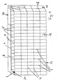
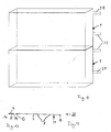
- the wire basket 1 shown in FIGS. 1 and 2 is used as a stem for Walls, in particular building walls, retaining walls, parapets, skeletal structures or similar walls. Several such Wire baskets 1 are placed next to and / or one above the other in front of a wall 2 (Fig. 14) arranged.
- the cuboid wire baskets 1 are in a known manner from in assembled position vertical and horizontal bars 3 made to 8, which cross each other and at the crossing points are welded together.
- the free ends 9 to 14 of the bars are loop-shaped in a known manner.
- the Wire baskets 1 consist of a front wall 15, a rear wall 16, Side walls 24, 25, a bottom 22 and a lid 17, the from the bars 3, 4 and 5, 6 and 7, 8 are formed.
- the walls and the cover 17 are via rod-like connecting parts 18, 19 and 20 (Fig. 20, 22, 23) connected to each other by the aligned loop-shaped ends 9 to 14 are inserted, such as is still described.
- the wire baskets 1 are in fastening parts 21 hung, which are attached to the wall 2.
- the wire baskets 1 are on the construction site with natural or artificial stones or some other suitable material. After closing the lid 17, the filled wire baskets 1 in the fasteners 21 hung.
- the wire baskets and are advantageous your fasteners made of stainless steel, galvanized steel, plastic-coated galvanized steel or combinations of these materials.
- the front grille 15 has an L-shape in side view a lower short leg 22, which by bending the lower End portions 23 of the undeformed front grille 15 is formed and forms the bottom of the wire basket 1.
- the front grille 15 consists of a large number of the same distance next to each other Longitudinal bars 3 and perpendicular to these transverse bars 4, which are also the same, but have a greater distance from each other than the longitudinal rods 3.
- the end portions 23 are through the over lower crossbar 4 projecting longitudinal bar sections formed.
- the Longitudinal and transverse bars 3, 4 can also have the same distance from one another from each other.
- the ends of all rods 3, 4 are closed the loops 9, 10 shaped.
- the rear wall 16 has a U-shape in plan view. It is like the front wall 15 through a flat grid with the longitudinal bars 5 and the cross bars 6 are formed. The distance of the longitudinal and Cross bars 5 and 6 from each other correspond to that of the longitudinal bars 3 and 4 of the front wall 15.
- the wall 16 is, as FIG. 8 shows, on its Narrow sides to form the side walls 24 and 25 at right angles bent. The end sections are off to form the side walls the penultimate vertical rod 5 bent on both sides. The ends 11, 12 of all wire rods 5, 6 are shaped into loops.
- the lid 17 according to FIGS. 11 and 12 of the mesh basket 1 is made exemplary from a longitudinal rod 7 and parallel with a greater distance juxtaposed cross bars 8.
- the ends 13, 14 of the Wire rods 7, 8 are shaped into loops.
- the different walls and the lid 17 are each made flat wire mesh. These items can already pre-assembled to complete baskets by the manufacturer, whereby only the lid 17 remains open and on site after filling the wire basket 1 is closed.
- the loop shown in FIG. 23 shown corner connector 20 inserted. This consists of one straight round rod with a hook-shaped bent end 26.
- the corner connector 20 is from below in the direction of arrow P in Fig. 2 through the aligned loops 10, 12 and through the lower loop of the side walls 24 and 25 inserted. At both Such a corner connector 20 becomes the side edges of the front grille 15 intended.
- the connecting part 19 (Fig. 22) is then inserted. It exists from a round wire, the ends 29 and 30 bent into a hook are. Then the hook-shaped ends 29, 30 of the Connecting part 19 suspended in the legs 27 of the corner connector 20.
- the lid is used to fasten the lid 17 to the front grille 15 with the loop-shaped ends 14 of its cross bars 8 to the upper Loops 9 of the longitudinal bars 3 of the front grille 15 created.
- a further connecting part 18 (Fig. 20 and 21) inserted that as a one-sided angled round rod is trained. It is inserted so far through the loops 9, 14 until with the angled end 31 into one of the side walls 24, 25 of the rear wall 16 can be threaded. After that, the end 32 bent at right angles (see Fig. 20).
- the connecting part 18 serves as a pivot axis for the cover 17. To secure it in the closed position, use the aligned loops 14 of the cross bars 8 of the cover 17 and the loops 9 at the upper edge of the rear wall 16 further connecting part 19 inserted after filling.
- spacers 47 (Fig. 2, 24) is provided. They consist of a round rod, the Ends 48, 49 in the assembled position hook-shaped inwards towards are bent towards each other.
- the spacers are preferably 47 arranged in the vertical and vertical direction of the wire basket 1. You can hang anywhere in the walls 15, 16 become.
- the spacers 47 encompass the ends 48, 49 of the Bars 3, 4 and 5, 6 at their crossing points.
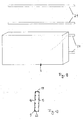
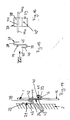
- the filled wire basket 1 is connected to the connecting parts 37 in the Wall 2 attached fasteners 21 hooked. They are equal educated.
- the fastening parts 21 are hanging rails with a flat, against the wall 2 abutting part 33, the lower Longitudinal edge 34 is bent like a hook.
- the system part 33 has Distance from each other in the longitudinal direction of the plant part 33 extending elongated holes 35 (FIG. 19) through the fastening parts, such as screws or the like, can be inserted. Over the slots 35 can achieve an optimal alignment with respect to the wall 2 become.
- There is at least one in the curved longitudinal edge 34 one, preferably several, spaced openings 36, through the water penetrating into the suspension rail 21 or the like can flow off.
- the spacer and suspension parts 47, 21, 37 can also be made of plastic consist.
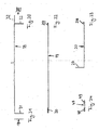
- the hanging rail 21 can also be designed so that its lower Longitudinal edge 34 'is U-shaped (Fig. 18).
- the plant part 33 ' has the elongated holes 35' and the U-shaped longitudinal edge 34 'at least a drain opening 36 '.
- the lower longitudinal edge of the rail 34 ' can also V-shaped with a lower drain opening 36 '.
- FIG. 18b shows a rail 34 'with a Z-shaped profile. she has a shorter leg 34 ', the cross bar 50 in a longer Leg 33 'merges, which forms the plant part. This has the openings or elongated holes 35 ', while the drain openings 36' in Transition area from the crosspiece 50 into the shorter leg 34 ' are provided.
- the rail 21 ' accordinging to Fig. 18c consists of the part 33', which as a flat Rail is formed, the elongated holes in one half 35 '. At the attachment points 35 'is a spacer used and the necessary wall clearance is set.
- All suspension parts 21, 21 ' can of course also as Individual suspension to be designed, for example, at an angle Buildings to be used at the transition to a slope.
- the wire baskets 1 instead of the two rails (Fig. 9 and 10) each have at least two suspension parts 21, 21 'at a distance provided side by side.
- the connecting parts 37 are on the rear wall 16 of the Wire basket 1 provided. So two rows of connectors can 37 may be provided, each row being at least two at a distance has adjacent connection parts 37.
- the connecting part 37 is of an approximately S-shaped bent sheet formed.
- the upper curved one in FIG. 14 End 38 is slightly lower than the lower curved end 39.
- Im free, upstanding leg 40 of the end 39 is a Push-through opening 40 'for a securing part 41, such as a screw (Fig. 14) provided.
- the connector 37 is at its end 39th suspended from below in one of the transverse wires 6 of the rear wall 16.
- the securing part 41 is then passed through the opening 40 used that it overlaps the cross wire 6.
- the connector 37 is thereby held captive on the wire basket 1.
- a stabilizing rod on the web 43 connecting the ends 38 and 39 44 attached To the connector 37 in its upright position relative to the rear wall 16, is a stabilizing rod on the web 43 connecting the ends 38 and 39 44 attached. It lies in the assembled position Fig. 14 slightly below the free edge 45 of the end 38 and protrudes on both sides via the connecting part 37. With the protruding rod ends 44a, 44b, the connecting part 37 is located on adjacent longitudinal bars 5 of the rear wall 16, so that a tilt-proof position is guaranteed is.
- the connecting part 37 lies with its web 43 within a mesh opening of the rear wall grille 16.
- the stabilizing bar 44 lies within the wire basket 1.
- the upper, curved end 38 protrudes backwards over the rear wall 16. With this end 38 that becomes Connection part 37 hooked into the fastening part 21. Since the attachment and the connecting part 21, 37 consist of flat material, extensive support is guaranteed. Because advantageously two Connection parts 37 are provided in each row, the wire basket 1 can be hung
- FIGS. 9 and 10 are for fastening the wire baskets 1st two suspension parts 21 arranged one above the other at a distance intended.
- the upper and lower suspension rails 21 serve for load absorption and transfer to the wall 2, the lower one Rail 21 also serves as a spacer and ensures that the wire basket 1 will not be unintentionally posted or can be lifted off the wall by wind suction.
- two wire baskets 1 are provided, which are each suspended in two suspension rails 21.
- the wire baskets 1 can be arranged one above the other and / or next to one another be to the walls 2 to the extent required or to partially cover.
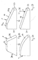
- baskets 1 can also be narrow and in special shapes 25 to 32 may be formed.
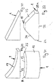
- 25 has the wire basket 1 in the side view the shape of an essentially isosceles Trapezes with a flat floor and a parallel cover and inclined side walls 24, 25.
- 26 has the bottom 22 and perpendicular to it Side walls 24, 25, of which one side wall 24 around is several times longer than the side wall 25.
- the basket 1 according to FIG. 27 largely corresponds to that according to FIG. 26.
- the cover 17 is curved outward in the form of a part circle.
- the basket 1 according to FIG. 29 corresponds to that according to FIG. 27; however he has a part-circular inward, towards the bottom 22 curved Lid 17.
- Fig. 30 shows a basket 1, the shape of a side view right triangle.
- the basket 1 has a rectangular shape with a partial circular shape outward or inward curved rear or front wall 16 or 15.
- the side walls 24, 25 are inclined accordingly.
- FIG. 32 shows a basket 1 which is similar to that of FIG. 25. however the lid 17 is shorter and the side walls 24 and 25 are short Sidewall sections 24a perpendicular to the bottom 22 and 25a.
- the wire baskets 1 can be pre-wire baskets fill it up while it is fastened to the floor with the filling material.
- the wire baskets 1 can then simply and when filled can be hooked into the suspension rails 21 without difficulty.
- the wire baskets 1 can be attached to the wall in such a way that they are arranged one above the other and side by side without gaps can.
- the hanging rails it is of course possible that several on the rails Wire baskets 1 can be arranged side by side.
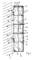
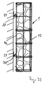
- Fig. 33 shows a further embodiment of a stem Mesh basket 1.
- this lattice basket essentially in that the Front wall 15 in the horizontal section U-shape and in the vertical section L-shape and that the rear wall 16 is formed as a simple flat grid is. Furthermore, there is no lid in the mesh basket according to FIG. 33 intended. Otherwise, the front and rear walls 15, 16 are essentially the same design as that of FIG. 1 crossing with each other Longitudinal and cross bars 3, 4 and 5, 6.
- the side walls 24 and 25 of the mesh basket 1 are through the U-legs and the basket bottom 22 through the L-leg of the formed as a molded part Front wall 15 formed.
- the side walls 24, 25 and the bottom 22 are formed in one piece with the end face 15 'of the front grille 15.
- the bottom 22 is by bending the lower parts of the longitudinal bars 3rd the front 15 'formed.
- the free ends 9 of the longitudinal bars 3 are like the ends 9 of the bottom 22 according to FIG. 3 like a loop or curved like a loop.
- the longitudinal bars 3 of the front side 15 ' close at the upper edge flush with the upper horizontal cross wire 4 '. This has the Advantage that at the front of the basket 1 no sharp Edges or protrusions are provided during handling of the mesh basket 1 could lead to injuries.
- Part of the vertical wires or rods 3, for example four of these wires, the Front wall 15 is at the upper end above the upper horizontal Cross wire 4 'bent backwards at right angles (FIGS. 34, 36).
- the free Ends 9 'of these wires 3 are like the ends 12 of the side walls 24, 25 U-shaped. They serve as hooks for the upper one horizontal cross wire 6 of the rear wall 16. Since only part of the Vertical wires 3 is bent at the top, are attached to this Narrow side of the mesh basket 1 large filling openings formed.
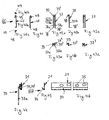
- FIG. 40, 41 On the rear wall 16 there are several spacers 47 (FIGS. 40, 41) attached at a right-angled end 48, preferably welded so that they protrude vertically over the wall surface (Fig. 38, 39). Its other ends 49 are bent in a U-shape. The end 49 is rotated by approximately 45 ° with respect to the end 48 (cf. FIG. 40c). Due to the rigid connection of the spacers 47 to the cross bars 6 of the rear wall 16, the spacers 47 are immovable on the Back wall secured. In the assembled position, the hook ends are 49 in Adjacent cross bars 4 of the front grille 15 are suspended. The hook-shaped Ends 49 encompass the bars 4 at the crossing points their transverse and longitudinal wires 3, 4, which is twisted by the Training of the ends 49 is reached.
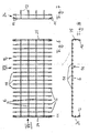
- connection parts 37, 37 ' (FIGS. 42a to 42c or 43a to 43c) for hanging in the mesh baskets 1 into the fastening parts 21 provided on the wall (FIGS. 44 to 46) attached to the rear wall 16, preferably welded.
- she are formed by a hairpin or U-shaped wire, which has two mutually parallel legs 37a, 37b. You are close their free ends 38, 38 'and near the hooks on cross wires 6 of the rear wall 16 welded.
- the arched one inside the other Transcending ends 39, 39 'of the connecting parts 37, 37' are hook-shaped bent outwards and form the hook, with which the connector is hooked into the holder 21. He is like that previously described embodiments as a rail with slot openings 35 and a curved longitudinal edge 34 formed in which the connecting part 37, 37 'hooked with its hook end 39, 39' 44 to 46).
- the legs 37a, 37b of the connecting parts 37 are relatively long, while the connecting parts 37 '(Fig. 43a to 43c) essential are shorter. Since the longer connecting parts 37 on two cross wires 6 are attached, they are securely held on the rear wall 16 and cannot inadvertently under the load of the existing in the mesh basket 1 Stones or the like can be demolished.
- the short ones Connecting parts 37 ' secure the basket 1 in its hanging on the wall Position if, for example, wind forces are acting on the basket. Without the securing via the connecting parts 37 ', the grid baskets would 1 under the wind force away from the wall and upwards pivoted so that the baskets themselves and their contents no longer would be properly secured.
- the mesh basket 1 On the top or filling side of the mesh basket 1 are due to the described Training no grid parts narrowing the cross section provided so that the mesh basket can be easily filled. There the mesh basket 1 has no lid on the filling side, and thereby is open at the top, it can be opened up to the upper rim of the basket fill completely. The stones can even go over the top of the basket 1 protrude, without thereby putting on the next Mesh basket 1 is impaired. This way is a gapless Stem 1 can be filled with stones.
- connection parts 37, 37 ' there are two upper ones on the rear wall 16 and two lower connecting parts 37, 37 'are provided.
- the lower, shorter ones Connection parts 37 ' are each aligned in height with the upper connecting parts 37.
- the free ends 48 are there at the corresponding ones Cross bars 6 welded. It can be beneficial instead of the two upper suspension parts 37 three with preferably the same Provide spacing between the hanging parts.
Landscapes
- Engineering & Computer Science (AREA)
- Architecture (AREA)
- Structural Engineering (AREA)
- Civil Engineering (AREA)
- Mining & Mineral Resources (AREA)
- Paleontology (AREA)
- General Life Sciences & Earth Sciences (AREA)
- General Engineering & Computer Science (AREA)
- Life Sciences & Earth Sciences (AREA)
- Environmental & Geological Engineering (AREA)
- Chemical & Material Sciences (AREA)
- Ceramic Engineering (AREA)
- Finishing Walls (AREA)
- Fencing (AREA)
- Pit Excavations, Shoring, Fill Or Stabilisation Of Slopes (AREA)
- Load-Bearing And Curtain Walls (AREA)
- Panels For Use In Building Construction (AREA)
Applications Claiming Priority (2)
| Application Number | Priority Date | Filing Date | Title |
|---|---|---|---|
| DE20218181U DE20218181U1 (de) | 2002-11-23 | 2002-11-23 | Vorbau für Wände, wie Gebäudewände, Stützwände, Brüstungen, Stahlkonstruktionen und dgl. |
| DE20218181U | 2002-11-23 |
Publications (3)
| Publication Number | Publication Date |
|---|---|
| EP1426521A2 true EP1426521A2 (fr) | 2004-06-09 |
| EP1426521A3 EP1426521A3 (fr) | 2006-03-15 |
| EP1426521B1 EP1426521B1 (fr) | 2012-03-14 |
Family
ID=7977280
Family Applications (1)
| Application Number | Title | Priority Date | Filing Date |
|---|---|---|---|
| EP03027002A Expired - Lifetime EP1426521B1 (fr) | 2002-11-23 | 2003-11-22 | Façade pour murs |
Country Status (4)
| Country | Link |
|---|---|
| EP (1) | EP1426521B1 (fr) |
| AT (1) | ATE549470T1 (fr) |
| DE (1) | DE20218181U1 (fr) |
| ES (1) | ES2384043T3 (fr) |
Cited By (11)
| Publication number | Priority date | Publication date | Assignee | Title |
|---|---|---|---|---|
| EP1739250A2 (fr) | 2005-07-01 | 2007-01-03 | Rothfuss, Thomas, Dipl.-Ing. | Support permettant de suspendre un revêtement de façade avec paniers en fils metalliques |
| EP1927706A2 (fr) | 2006-12-02 | 2008-06-04 | Stones & More GmbH & Co. KG | Revêtement mural pour une façade |
| DE202008012264U1 (de) | 2008-09-16 | 2008-11-27 | Lehrhuber, Konrad | Wandverkleidung mit Füllmaterial und Funktionsschicht |
| DE202008012263U1 (de) | 2008-09-16 | 2008-11-27 | Lehrhuber, Konrad | Wandverkleidung mit Füllmaterial |
| EP2163705A2 (fr) | 2008-09-16 | 2010-03-17 | Konrad Lehrhuber | Habillage mural doté d'un matériau de remplissage et d'une couche fonctionnelle |
| DE202010007175U1 (de) | 2010-05-25 | 2010-08-26 | Triooo Building Systems Gmbh | Vorhangfassade mit Dämmung |
| WO2011033142A1 (fr) * | 2009-09-15 | 2011-03-24 | Grupo Leon Lebrero División Geotécnica, S.L. | Gabion pour tout type de pierres naturelles et de résidus |
| EP2390436A1 (fr) | 2010-05-25 | 2011-11-30 | TRiooo Building Systems GmbH | Mur-rideau doté d'une isolation |
| DE202013011502U1 (de) | 2013-12-30 | 2014-03-25 | Wolfgang Deutschle | Fassadenverkleidungsgabione |
| EP2907763A1 (fr) * | 2014-02-14 | 2015-08-19 | Rothfuss GmbH u. Co. KG | Revêtement mural doté de corbeilles en treillis métallique et corbeille en treillis métallique |
| WO2016184473A1 (fr) * | 2015-05-21 | 2016-11-24 | Komproment Holding Af 2007 Aps | Système de rail |
Families Citing this family (1)
| Publication number | Priority date | Publication date | Assignee | Title |
|---|---|---|---|---|
| CN110344522B (zh) * | 2019-07-25 | 2021-07-23 | 李建镇 | 一次成型墙体的施工方法及一次成型墙体建筑施工方法 |
Citations (2)
| Publication number | Priority date | Publication date | Assignee | Title |
|---|---|---|---|---|
| US5860551A (en) | 1997-04-07 | 1999-01-19 | Knott, Sr.; James M. | Gabion container |
| DE20207327U1 (de) | 2002-05-10 | 2002-08-08 | Rothfuss Thomas | Vorbau für Fassaden von Gebäuden |
Family Cites Families (6)
| Publication number | Priority date | Publication date | Assignee | Title |
|---|---|---|---|---|
| US3621635A (en) * | 1970-03-02 | 1971-11-23 | Cement Enamel Dev Inc | Panel wall |
| NO141225L (fr) * | 1974-03-25 | |||
| US3912211A (en) * | 1974-06-28 | 1975-10-14 | Jordan Ind Inc | Picture hook |
| DE3110606A1 (de) * | 1981-03-18 | 1982-09-30 | Herzog, Thomas, Prof. Dr., 8000 München | Vorrichtung zur befestigung einer fassadenplatte |
| WO1997027404A2 (fr) * | 1996-01-24 | 1997-07-31 | Glynwed International Plc | Ameliorations apportes aux pieces d'attache |
| NL1019892C2 (nl) * | 2001-02-05 | 2002-09-26 | Gelder Pennings Metaal B V Van | Vernieuwde schanskorf voor gebruik als wand- of gevelelement. |
-
2002
- 2002-11-23 DE DE20218181U patent/DE20218181U1/de not_active Expired - Lifetime
-
2003
- 2003-11-22 EP EP03027002A patent/EP1426521B1/fr not_active Expired - Lifetime
- 2003-11-22 ES ES03027002T patent/ES2384043T3/es not_active Expired - Lifetime
- 2003-11-22 AT AT03027002T patent/ATE549470T1/de active
Patent Citations (2)
| Publication number | Priority date | Publication date | Assignee | Title |
|---|---|---|---|---|
| US5860551A (en) | 1997-04-07 | 1999-01-19 | Knott, Sr.; James M. | Gabion container |
| DE20207327U1 (de) | 2002-05-10 | 2002-08-08 | Rothfuss Thomas | Vorbau für Fassaden von Gebäuden |
Cited By (17)
| Publication number | Priority date | Publication date | Assignee | Title |
|---|---|---|---|---|
| EP1739250A3 (fr) * | 2005-07-01 | 2009-06-17 | Rothfuss, Thomas, Dipl.-Ing. | Support permettant de suspendre un revêtement de façade avec paniers en fils metalliques |
| EP1739250A2 (fr) | 2005-07-01 | 2007-01-03 | Rothfuss, Thomas, Dipl.-Ing. | Support permettant de suspendre un revêtement de façade avec paniers en fils metalliques |
| EP1927706A2 (fr) | 2006-12-02 | 2008-06-04 | Stones & More GmbH & Co. KG | Revêtement mural pour une façade |
| EP1927706A3 (fr) * | 2006-12-02 | 2010-01-13 | Stones & More GmbH & Co. KG | Revêtement mural pour une façade |
| DE202008012264U1 (de) | 2008-09-16 | 2008-11-27 | Lehrhuber, Konrad | Wandverkleidung mit Füllmaterial und Funktionsschicht |
| DE202008012263U1 (de) | 2008-09-16 | 2008-11-27 | Lehrhuber, Konrad | Wandverkleidung mit Füllmaterial |
| EP2163705A2 (fr) | 2008-09-16 | 2010-03-17 | Konrad Lehrhuber | Habillage mural doté d'un matériau de remplissage et d'une couche fonctionnelle |
| EP2163706A2 (fr) | 2008-09-16 | 2010-03-17 | Konrad Lehrhuber | Habillage mural doté d'un matériau de remplissage |
| WO2011033142A1 (fr) * | 2009-09-15 | 2011-03-24 | Grupo Leon Lebrero División Geotécnica, S.L. | Gabion pour tout type de pierres naturelles et de résidus |
| DE202010007175U1 (de) | 2010-05-25 | 2010-08-26 | Triooo Building Systems Gmbh | Vorhangfassade mit Dämmung |
| EP2390436A1 (fr) | 2010-05-25 | 2011-11-30 | TRiooo Building Systems GmbH | Mur-rideau doté d'une isolation |
| DE202013011502U1 (de) | 2013-12-30 | 2014-03-25 | Wolfgang Deutschle | Fassadenverkleidungsgabione |
| EP2894274A2 (fr) | 2013-12-30 | 2015-07-15 | Wolfgang Deutschle | Gabion de revêtement de façade |
| EP2907763A1 (fr) * | 2014-02-14 | 2015-08-19 | Rothfuss GmbH u. Co. KG | Revêtement mural doté de corbeilles en treillis métallique et corbeille en treillis métallique |
| WO2016184473A1 (fr) * | 2015-05-21 | 2016-11-24 | Komproment Holding Af 2007 Aps | Système de rail |
| US10316524B2 (en) | 2015-05-21 | 2019-06-11 | Komproment Holding Af 2007 Aps | Rail system |
| EA035553B1 (ru) * | 2015-05-21 | 2020-07-07 | Компромент Холдинг Аф 2007 Апс | Направляющая система для установки облицовочных элементов на фасаде |
Also Published As
| Publication number | Publication date |
|---|---|
| EP1426521B1 (fr) | 2012-03-14 |
| DE20218181U1 (de) | 2003-03-27 |
| ES2384043T3 (es) | 2012-06-28 |
| ATE549470T1 (de) | 2012-03-15 |
| EP1426521A3 (fr) | 2006-03-15 |
Similar Documents
| Publication | Publication Date | Title |
|---|---|---|
| DE50104528C5 (de) | Steinkorb | |
| DE3403165A1 (de) | Vorrichtung zur bodenstabilisierung im wasserbau | |
| EP1426521B1 (fr) | Façade pour murs | |
| DE2948230C2 (de) | Schnurgerüststütze mit Verankerungsvorrichtung | |
| DE4208964C2 (de) | Steilböschungsbaute | |
| WO2022033935A1 (fr) | Élément de paroi cultivable | |
| DE3411313A1 (de) | Lager- bzw. speicher- und/oder ausstellungseinrichtung | |
| EP0356820B1 (fr) | Treillis pour faire pousser des plantes sur des façades | |
| EP2305889B1 (fr) | Corbeille en fil métallique et entretoise pour l'utilisation dans des corbeilles en fil métallique | |
| EP1498552A1 (fr) | Gabion | |
| DE4436345C1 (de) | Gitterzaun mit einrastenden Haltebügeln | |
| DE3920108C1 (fr) | ||
| DE102014111631B4 (de) | Verfahren zur Montage einer Gabione, Verbinder, Hängelasche und Bausatz zur Erstellung von nach dem Verfahren montierbaren Gabionen | |
| DE3146564A1 (de) | Abdeckrost fuer entmistungskanaele in viehstaellen | |
| DE3822621C2 (fr) | ||
| EP1739250A2 (fr) | Support permettant de suspendre un revêtement de façade avec paniers en fils metalliques | |
| DE10116782A1 (de) | Befestigungsvorrichtung für flächige Solarkomponenten | |
| EP2312062B1 (fr) | Gabione | |
| DE4409538A1 (de) | Einrichtung zum Erstellen vorzugsweise begrünbarer Böschungen | |
| DE4134800C1 (en) | Recycled plastics sound barrier wall - has triangular cross=section with pockets to receive plants | |
| DE102004037909B4 (de) | Anordnung zur hängenden Halterung von Schallabsorbern | |
| EP1247590B1 (fr) | Dispositif pour dévier, retenir et/ou guider des matières sur une surface de tamisage | |
| DE202007004127U1 (de) | Bepflanzbare Kräuterspirale | |
| DE10101322B4 (de) | Begrenzungselement für eine Rasenkantenbegrenzung | |
| EP1776901A1 (fr) | Support d'étagère avec crochets de serrage |
Legal Events
| Date | Code | Title | Description |
|---|---|---|---|
| PUAI | Public reference made under article 153(3) epc to a published international application that has entered the european phase |
Free format text: ORIGINAL CODE: 0009012 |
|
| AK | Designated contracting states |
Kind code of ref document: A2 Designated state(s): AT BE BG CH CY CZ DE DK EE ES FI FR GB GR HU IE IT LI LU MC NL PT RO SE SI SK TR |
|
| AX | Request for extension of the european patent |
Extension state: AL LT LV MK |
|
| RTI1 | Title (correction) |
Free format text: FAEADE FOR WALLS |
|
| PUAL | Search report despatched |
Free format text: ORIGINAL CODE: 0009013 |
|
| AK | Designated contracting states |
Kind code of ref document: A3 Designated state(s): AT BE BG CH CY CZ DE DK EE ES FI FR GB GR HU IE IT LI LU MC NL PT RO SE SI SK TR |
|
| AX | Request for extension of the european patent |
Extension state: AL LT LV MK |
|
| 17P | Request for examination filed |
Effective date: 20060812 |
|
| 17Q | First examination report despatched |
Effective date: 20060926 |
|
| AKX | Designation fees paid |
Designated state(s): AT BE BG CH CY CZ DE DK EE ES FI FR GB GR HU IE IT LI LU MC NL PT RO SE SI SK TR |
|
| GRAP | Despatch of communication of intention to grant a patent |
Free format text: ORIGINAL CODE: EPIDOSNIGR1 |
|
| RTI1 | Title (correction) |
Free format text: FACADE FOR WALLS |
|
| GRAS | Grant fee paid |
Free format text: ORIGINAL CODE: EPIDOSNIGR3 |
|
| GRAA | (expected) grant |
Free format text: ORIGINAL CODE: 0009210 |
|
| AK | Designated contracting states |
Kind code of ref document: B1 Designated state(s): AT BE BG CH CY CZ DE DK EE ES FI FR GB GR HU IE IT LI LU MC NL PT RO SE SI SK TR |
|
| REG | Reference to a national code |
Ref country code: GB Ref legal event code: FG4D Free format text: NOT ENGLISH |
|
| REG | Reference to a national code |
Ref country code: CH Ref legal event code: EP Ref country code: AT Ref legal event code: REF Ref document number: 549470 Country of ref document: AT Kind code of ref document: T Effective date: 20120315 |
|
| REG | Reference to a national code |
Ref country code: DE Ref legal event code: R081 Ref document number: 50314263 Country of ref document: DE Owner name: AXEL FRIEDHOFF GMBH & CO. KG, DE Free format text: FORMER OWNER: ROTHFUSS, THOMAS, 71735 EBERDINGEN, DE |
|
| REG | Reference to a national code |
Ref country code: IE Ref legal event code: FG4D Free format text: LANGUAGE OF EP DOCUMENT: GERMAN |
|
| REG | Reference to a national code |
Ref country code: DE Ref legal event code: R096 Ref document number: 50314263 Country of ref document: DE Effective date: 20120510 |
|
| REG | Reference to a national code |
Ref country code: ES Ref legal event code: FG2A Ref document number: 2384043 Country of ref document: ES Kind code of ref document: T3 Effective date: 20120628 |
|
| REG | Reference to a national code |
Ref country code: NL Ref legal event code: VDEP Effective date: 20120314 |
|
| PG25 | Lapsed in a contracting state [announced via postgrant information from national office to epo] |
Ref country code: GR Free format text: LAPSE BECAUSE OF FAILURE TO SUBMIT A TRANSLATION OF THE DESCRIPTION OR TO PAY THE FEE WITHIN THE PRESCRIBED TIME-LIMIT Effective date: 20120615 Ref country code: FI Free format text: LAPSE BECAUSE OF FAILURE TO SUBMIT A TRANSLATION OF THE DESCRIPTION OR TO PAY THE FEE WITHIN THE PRESCRIBED TIME-LIMIT Effective date: 20120314 |
|
| PG25 | Lapsed in a contracting state [announced via postgrant information from national office to epo] |
Ref country code: CY Free format text: LAPSE BECAUSE OF FAILURE TO SUBMIT A TRANSLATION OF THE DESCRIPTION OR TO PAY THE FEE WITHIN THE PRESCRIBED TIME-LIMIT Effective date: 20120314 |
|
| PG25 | Lapsed in a contracting state [announced via postgrant information from national office to epo] |
Ref country code: SI Free format text: LAPSE BECAUSE OF FAILURE TO SUBMIT A TRANSLATION OF THE DESCRIPTION OR TO PAY THE FEE WITHIN THE PRESCRIBED TIME-LIMIT Effective date: 20120314 Ref country code: CZ Free format text: LAPSE BECAUSE OF FAILURE TO SUBMIT A TRANSLATION OF THE DESCRIPTION OR TO PAY THE FEE WITHIN THE PRESCRIBED TIME-LIMIT Effective date: 20120314 Ref country code: RO Free format text: LAPSE BECAUSE OF FAILURE TO SUBMIT A TRANSLATION OF THE DESCRIPTION OR TO PAY THE FEE WITHIN THE PRESCRIBED TIME-LIMIT Effective date: 20120314 Ref country code: EE Free format text: LAPSE BECAUSE OF FAILURE TO SUBMIT A TRANSLATION OF THE DESCRIPTION OR TO PAY THE FEE WITHIN THE PRESCRIBED TIME-LIMIT Effective date: 20120314 Ref country code: SE Free format text: LAPSE BECAUSE OF FAILURE TO SUBMIT A TRANSLATION OF THE DESCRIPTION OR TO PAY THE FEE WITHIN THE PRESCRIBED TIME-LIMIT Effective date: 20120314 |
|
| PG25 | Lapsed in a contracting state [announced via postgrant information from national office to epo] |
Ref country code: PT Free format text: LAPSE BECAUSE OF FAILURE TO SUBMIT A TRANSLATION OF THE DESCRIPTION OR TO PAY THE FEE WITHIN THE PRESCRIBED TIME-LIMIT Effective date: 20120716 Ref country code: SK Free format text: LAPSE BECAUSE OF FAILURE TO SUBMIT A TRANSLATION OF THE DESCRIPTION OR TO PAY THE FEE WITHIN THE PRESCRIBED TIME-LIMIT Effective date: 20120314 |
|
| PLBE | No opposition filed within time limit |
Free format text: ORIGINAL CODE: 0009261 |
|
| STAA | Information on the status of an ep patent application or granted ep patent |
Free format text: STATUS: NO OPPOSITION FILED WITHIN TIME LIMIT |
|
| PG25 | Lapsed in a contracting state [announced via postgrant information from national office to epo] |
Ref country code: DK Free format text: LAPSE BECAUSE OF FAILURE TO SUBMIT A TRANSLATION OF THE DESCRIPTION OR TO PAY THE FEE WITHIN THE PRESCRIBED TIME-LIMIT Effective date: 20120314 Ref country code: NL Free format text: LAPSE BECAUSE OF FAILURE TO SUBMIT A TRANSLATION OF THE DESCRIPTION OR TO PAY THE FEE WITHIN THE PRESCRIBED TIME-LIMIT Effective date: 20120314 |
|
| 26N | No opposition filed |
Effective date: 20121217 |
|
| REG | Reference to a national code |
Ref country code: DE Ref legal event code: R097 Ref document number: 50314263 Country of ref document: DE Effective date: 20121217 |
|
| BERE | Be: lapsed |
Owner name: ROTHFUSS, THOMAS, DIPL.-ING. Effective date: 20121130 |
|
| REG | Reference to a national code |
Ref country code: CH Ref legal event code: PL |
|
| GBPC | Gb: european patent ceased through non-payment of renewal fee |
Effective date: 20121122 |
|
| PG25 | Lapsed in a contracting state [announced via postgrant information from national office to epo] |
Ref country code: LI Free format text: LAPSE BECAUSE OF NON-PAYMENT OF DUE FEES Effective date: 20121130 Ref country code: BG Free format text: LAPSE BECAUSE OF FAILURE TO SUBMIT A TRANSLATION OF THE DESCRIPTION OR TO PAY THE FEE WITHIN THE PRESCRIBED TIME-LIMIT Effective date: 20120614 Ref country code: CH Free format text: LAPSE BECAUSE OF NON-PAYMENT OF DUE FEES Effective date: 20121130 |
|
| REG | Reference to a national code |
Ref country code: IE Ref legal event code: MM4A |
|
| REG | Reference to a national code |
Ref country code: FR Ref legal event code: ST Effective date: 20130731 |
|
| PG25 | Lapsed in a contracting state [announced via postgrant information from national office to epo] |
Ref country code: BE Free format text: LAPSE BECAUSE OF NON-PAYMENT OF DUE FEES Effective date: 20121130 |
|
| PG25 | Lapsed in a contracting state [announced via postgrant information from national office to epo] |
Ref country code: IE Free format text: LAPSE BECAUSE OF NON-PAYMENT OF DUE FEES Effective date: 20121122 |
|
| PG25 | Lapsed in a contracting state [announced via postgrant information from national office to epo] |
Ref country code: FR Free format text: LAPSE BECAUSE OF NON-PAYMENT OF DUE FEES Effective date: 20121130 Ref country code: GB Free format text: LAPSE BECAUSE OF NON-PAYMENT OF DUE FEES Effective date: 20121122 |
|
| REG | Reference to a national code |
Ref country code: AT Ref legal event code: MM01 Ref document number: 549470 Country of ref document: AT Kind code of ref document: T Effective date: 20121130 |
|
| PG25 | Lapsed in a contracting state [announced via postgrant information from national office to epo] |
Ref country code: AT Free format text: LAPSE BECAUSE OF NON-PAYMENT OF DUE FEES Effective date: 20121130 |
|
| PGFP | Annual fee paid to national office [announced via postgrant information from national office to epo] |
Ref country code: IT Payment date: 20131022 Year of fee payment: 11 Ref country code: ES Payment date: 20131105 Year of fee payment: 11 |
|
| PG25 | Lapsed in a contracting state [announced via postgrant information from national office to epo] |
Ref country code: MC Free format text: LAPSE BECAUSE OF NON-PAYMENT OF DUE FEES Effective date: 20121130 Ref country code: TR Free format text: LAPSE BECAUSE OF FAILURE TO SUBMIT A TRANSLATION OF THE DESCRIPTION OR TO PAY THE FEE WITHIN THE PRESCRIBED TIME-LIMIT Effective date: 20120314 |
|
| PG25 | Lapsed in a contracting state [announced via postgrant information from national office to epo] |
Ref country code: LU Free format text: LAPSE BECAUSE OF NON-PAYMENT OF DUE FEES Effective date: 20121122 |
|
| PG25 | Lapsed in a contracting state [announced via postgrant information from national office to epo] |
Ref country code: HU Free format text: LAPSE BECAUSE OF FAILURE TO SUBMIT A TRANSLATION OF THE DESCRIPTION OR TO PAY THE FEE WITHIN THE PRESCRIBED TIME-LIMIT Effective date: 20031122 |
|
| PG25 | Lapsed in a contracting state [announced via postgrant information from national office to epo] |
Ref country code: IT Free format text: LAPSE BECAUSE OF NON-PAYMENT OF DUE FEES Effective date: 20141122 |
|
| REG | Reference to a national code |
Ref country code: DE Ref legal event code: R082 Ref document number: 50314263 Country of ref document: DE Representative=s name: JACKISCH-KOHL UND KOHL, DE Ref country code: DE Ref legal event code: R081 Ref document number: 50314263 Country of ref document: DE Owner name: AXEL FRIEDHOFF GMBH & CO. KG, DE Free format text: FORMER OWNER: ROTHFUSS, THOMAS, 71735 EBERDINGEN, DE |
|
| PG25 | Lapsed in a contracting state [announced via postgrant information from national office to epo] |
Ref country code: ES Free format text: LAPSE BECAUSE OF NON-PAYMENT OF DUE FEES Effective date: 20141123 |
|
| PGFP | Annual fee paid to national office [announced via postgrant information from national office to epo] |
Ref country code: DE Payment date: 20230126 Year of fee payment: 20 |
|
| REG | Reference to a national code |
Ref country code: DE Ref legal event code: R071 Ref document number: 50314263 Country of ref document: DE |