EP2473004B1 - Helligkeitssteuerung einer Statusanzeigeleuchte - Google Patents
Helligkeitssteuerung einer Statusanzeigeleuchte Download PDFInfo
- Publication number
- EP2473004B1 EP2473004B1 EP20110190911 EP11190911A EP2473004B1 EP 2473004 B1 EP2473004 B1 EP 2473004B1 EP 20110190911 EP20110190911 EP 20110190911 EP 11190911 A EP11190911 A EP 11190911A EP 2473004 B1 EP2473004 B1 EP 2473004B1
- Authority
- EP
- European Patent Office
- Prior art keywords
- luminance
- led
- light
- target
- change
- Prior art date
- Legal status (The legal status is an assumption and is not a legal conclusion. Google has not performed a legal analysis and makes no representation as to the accuracy of the status listed.)
- Not-in-force
Links
Images


Classifications
-
- H—ELECTRICITY
- H05—ELECTRIC TECHNIQUES NOT OTHERWISE PROVIDED FOR
- H05B—ELECTRIC HEATING; ELECTRIC LIGHT SOURCES NOT OTHERWISE PROVIDED FOR; CIRCUIT ARRANGEMENTS FOR ELECTRIC LIGHT SOURCES, IN GENERAL
- H05B45/00—Circuit arrangements for operating light-emitting diodes [LED]
- H05B45/10—Controlling the intensity of the light
Definitions
- the present invention generally relates to the field of illumination control and more particularly involves luminance control of lights.
- Electronic devices such as computers, personal digital assistants, monitors, portable DVD players, and portable music players such as MP3 players typically have multiple power states.
- Two exemplary power states are “on” when the device is operating at full power and “off” when the device is turned off and uses very little or no power.
- Another exemplary power state is “sleep” when the device is turned on but uses less power than when in the "on” state, typically because one or more features of the device are disabled or suspended.
- Yet another exemplary power state is "hibernate” when the device's state is saved to non-volatile storage (typically the system's hard drive) and then the device is turned off. Sleep or hibernate states are typically used to reduce energy consumption, save battery life and enable the device to return to the "on” state more quickly than from the "off” state.
- Fig. 1 is a perspective view of a computer system according to the prior art.
- a user may interact with the computer 100 and/or the display 105 using an input device, such as a keyboard 110 or a mouse 115.
- a button 120 may be used to turn on the computer 100 or the display 105.
- a light emitting diode (“LED") 125 may be used as a status indicator to provide information to a user regarding a current power state of the computer 100 or the display 105, and optionally other operational information, such as diagnostic codes.
- the LED 125 When the computer 100 or the display 105 is turned on, the LED 125 emits light that is seen by the user.
- the LED 125 pulses to alert the user the computer is in the sleep state.
- Other prior art systems may include more complex LED behavior.
- the LED may be combined with button 120 made of a transparent material that covers or overlays the LED. The light emitted by the LED is transmitted through the button and is seen by the user.
- the perceived brightness of the LED 125 depends on the contrast between (1) the ambient light reflecting off the area surrounding the LED and (2) the light emanating directly from the LED, due to the way the human eye functions.
- the human eye registers differences in contrast rather than absolutes.
- a light that has an unchanging absolute brightness appears much brighter in a dark room than outdoors on a sunny day.
- the way the eye perceives the brightness of the LED is by its contrast relative to the ambient light reflected off the area surrounding the LED.
- the light emitted by the LED can be distracting or disruptive to the user.
- Prior art has developed means of sensing the ambient light level and adjusting the LED's luminance in order to maintain a constant perceived brightness (i.e., constant contrast) as the ambient light changes.
- Prior art has also achieved partial success in controlling the rate at which the LED's luminance changes so that the user perceives an approximately linear rate of change in brightness regardless of the ambient light level. What is needed are improved methods of controlling the brightness of the LED when it is changing so that the user perceives smoother changes in the brightness of the LED to provide a more pleasing visual effect under a variety of ambient lighting conditions.
- JP 6 318050 A discloses an image display device with a luminance adjusting function needlessly attracting no operator's notice when dark light emitting display at a night condition is changed to bright light emitting display at a day condition and making no operator's normal sight lose, related to the image display device with the luminance adjusting function properly adjusting the luminance in the light emitting display in a vehicle while adapting to a difference between the day and the night conditions set to a vehicle side.
- JP 2006 041043 A discloses an LED drive circuit capable of automatically repeating fade-in and fade-out of an LED.
- JP 2000 098942 A discloses an illumination signboard which slowly and variously functionally changes the luminance at the time of light emission and at the time of extinction of the illumination signboard using LEDs, thereby respectively independently changing the luminance of the LED groups of many channels.
- US 2006/033443 A1 discloses an LED control circuit for controlling a plurality of LEDs with different emission colors comprising a counter which increments or decrements a count value at a predetermined clock in response to a count start signal externally supplied, a signal conversion circuit which converts the count value into an analog signal displaying intensity corresponding to the count value and outputs the analog signal as an output signal, a signal generation circuit which generates, based on the output signal from the signal conversion circuit and brightness data externally specified to its corresponding LED, an analog signal displaying intensity corresponding to a product of the output signal and the brightness data, and a driving circuit which drives its corresponding LED according to the analog signal output from the signal generation circuit, to gradually and simultaneously change the brightness of the LEDs in accordance with the count value.
- one embodiment of the present invention takes the form of an apparatus for controlling the brightness and luminance of an LED.
- the embodiment may vary the brightness and luminance of the LED in a variety of ways to achieve a variety of effects.
- the exemplary embodiment may vary the rate at which the LED's luminance changes, such that an observer perceives the change in the LED's brightness to be smooth and linear as a function of time, regardless of the ambient light level.
- luminance generally refers to the actual, objective light output of a device
- brightness generally refers to the perceived, subjective light output of a device.
- a user will perceive a brightness in response to an LED's luminance.
- the perceived instantaneous brightness of an LED is affected by many factors, such as the brightness of the surrounding area, rate of change in luminance over time, and so forth, that do not necessarily affect the LED's instantaneous luminance.
- Another exemplary embodiment of the present invention may vary the luminance of an LED to avoid a sudden discontinuity in brightness.
- the embodiment may vary the LED's luminance in such a manner as to avoid the impression of the LED abruptly changing from an illuminated state to an off state.
- This perceptual phenomenon is referred to herein as a "cliff.” Cliffs may be perceived even when the luminance of the LED is such that the LED is still technically on. Further, cliffs may occur in the opposite direction, i.e., when the LED is brightening. In such an operation, the LED may appear to steadily brighten then abruptly snap or jump to a higher brightness instead of continuing to steadily brighten.
- Another embodiment of the present invention may adjust the LED's luminance to avoid or minimize the creation of such a cliff.
- Yet another exemplary embodiment of the present invention takes the form of a method for varying a luminance of a light, including the operations of varying an input to the light, the input affecting the luminance, setting a threshold value for the luminance of the light, and adjusting a rate of change of the input when the luminance is below the threshold.
- This exemplary embodiment may also include the operations of determining a target luminance to be reached by the luminance of the light, determining a minimum time in which the target luminance may be reached, setting a minimum number of increments necessary to vary the luminance from an initial luminance to the target luminance, and changing the luminance of the light from the initial luminance to the target luminance in a number of increments at least equal to the minimum number of increments.
- Still another exemplary embodiment of the present invention takes the form of a method for varying a luminance of a light, including the operations of determining a target change in a signal, the signal setting the luminance of the light, determining the lesser of the target change and a maximum allowed change, and limiting a change in the signal to the lesser of the target change and the maximum allowed change, thereby limiting a rate of change in the luminance of the light.
- a further embodiment of the present invention takes the form of a method for varying a luminance of a light, including the operations of setting a target luminance of the light, and changing the luminance of the light from a current luminance to the target luminance, wherein the operation of changing the luminance of the light from the current luminance to the target luminance occurs within a predetermined time.
- Still another embodiment of the present invention takes the form of a method for changing a luminance of a light, including the operations of determining a target luminance to be reached by the luminance of the light, determining a minimum time in which the target luminance may be reached, setting a minimum number of increments necessary to vary the luminance from an initial luminance to the target luminance, and changing the luminance of the light from the initial luminance to the target luminance in a number of increments at least equal to the minimum number of increments.
- an LED is equally applicable to any light-emitting element, including a cathode ray tube (CRT), liquid crystal display (LCD), fluorescent light, television, and so forth. Accordingly, the general operations described herein may be employed with a number of different devices. Further, although several of the embodiments described herein specifically discuss a digital implementation, analog embodiments are also embraced by the present invention. As an example, an analog embodiment may vary voltage to a light source instead of varying a pulse-width modulation duty cycle. Alternatively, a digital or analog-controlled current source could be used to control the light-emitting element.
- a status indicator light such as a light-emitting diode (“LED"), used to indicate whether the device is in its off state (e.g., LED off), its on state (e.g., LED on) or other power states such as its sleep state (e.g., LED pulses).
- LED light-emitting diode
- the luminance of the LED may be ramped from one luminance level to another luminance level to avoid too rapid of a change in brightness, which may be distracting to the user.
- the term “brightness” refers to how bright the LED appears to the eye and the term “luminance” refers to the absolute intensity of light output of the LED. Because of the non-linearity of human perception of luminance change, which is based in part on contrast, a. linear change in luminance over time may not appear as a linear change in brightness to the user.
- the human eye needs contrast between the point source and its background. This is why a bright star is clearly visible in the dark night sky, yet completely invisible to the eye through sunlight scattered by the atmosphere during the daylight hours. Similarly, the eye can only perceive the brightness of a system status light, such as an LED, when sufficient contrast exists between the LED and the ambient light reflected off a surrounding bezel.
- a system status light such as an LED
- the perceived brightness of an LED generally is a function of (1) the type of LED, (2) the electrical current flowing through the LED, (3) the transmissivity of the light transmission path between the LED and the user, (4) the viewing angle, and (5) the contrast between the light emitted from the LED and the light reflected by the surrounding area, such as the bezel.
- the amount of incident light reflected by the bezel is a function of, among other things, the ambient lighting conditions (including the location, type, and luminance of all ambient light sources), the viewing angle, the color of the bezel, and whether the bezel has a matte or shiny finish.
- An ambient light sensor may be used to measure the incident light falling on the bezel.
- the reflectivity of the bezel can be determined during the design phase of a product.
- the LED brightness may be controlled by manipulating its luminance to produce perceived smooth (possibly linear) changes in brightness as the LED is turned on, turned off, brightened, dimmed or pulsed, regardless of the ambient lighting conditions.
- This provides the user with a system status indicator light that has a pleasing visual effect under a wide variety of ambient lighting conditions.
- An LED produces light in response to an electrical current flowing through the LED.
- the amount of light produced is typically proportional to the amount of current flowing through the LED.
- the luminance of the LED can be adjusted by varying the current flow.
- the color of the light emitted by an LED is a function of the instantaneous current flow through the LED, while the average luminance of the LED is a function of the average current flow through the LED.
- the "on current" through the LED should be maintained at a constant value as the duty cycle of that current is varied.
- a pulse-width modulator (“PWM") control circuit may be used by some embodiments of the present invention to control the luminance of an LED status indicator light at a given color.
- the luminance of the LED is determined by the duty cycle of a PWM generator which determines the average LED current flow.
- One exemplary embodiment implements a variable slew rate control that reduces the rate of change in luminance of the LED below a tunable threshold luminance value to minimize the cliff effect.
- the PWM control circuit 200 may include a PWM generator 210 with a 16 bit control register 215, a transistor switch 220, a power supply 225 and a current-limiting resistor 230 that controls the instantaneous luminance of the LED 205 when it is on.
- the PWM generator 210 produces a pulse-wave output with a duty cycle determined by the control register 215.
- the output voltage drives the control input of the transistor switch 220.
- a control register value of 0 results in the PWM generator 210 producing an output signal with a zero duty cycle. This turns the LED off because no current flows through the LED.
- a control register value of 65535 produces an output signal from the PWM generator with a duty cycle of 100%.
- the remaining intermediate control register 215 values may be used to vary the average luminance of the LED 205 by controlling the duty cycle of the PWM generator 210, i.e., intermediate register values yield intermediate average luminances.
- Other embodiments may use a PWM control register with more or fewer bits.
- Fig. 2 depicts an elementary circuit. Certain embodiments of the present invention may employ more sophisticated LED drive circuits than depicted. For example, a constant current source may be used instead of a current-limiting resistor to set the current magnitude.
- the PWM control circuit may ramp the average luminance of the LED from on to off (or off to on) rather than instantaneously stepping the average luminance of the LED from on to off (or off to on), i.e., by ramping the PWM value down from the on value to the off value (or up from the off value to the on value) over a specified period of time.
- the ramp duration may be approximately one-half second in one embodiment of the present invention.
- the ramp duration may correspond to a specified number of PWM update cycles (herein referred to as ticks), for example, 76 ticks in one embodiment, with the ticks occurring at a. rate of 152 ticks per second.
- the PWM control register value sets the duty cycle of the PWM generator's output signal waveform which in turn sets the average current flow through the LED.
- Changing the duty cycle of the signal waveform over time can be used to animate the luminance of the LED and adjust a brightness waveform perceived by the user.
- the "brightness waveform" refers to the perceived brightness of the LED over time as seen by an observer.
- Other embodiments may use a ramp duration that is longer or shorter than half a second and may use PWM update cycles that are longer or shorter.
- Fig. 3A shows an example of a desired perceived brightness 300 of the LED status indicator as the PWM generator ramps the average LED luminance from the "on" state to the "off” state by reducing the PWM value using a linear contrast curve 305, shown in Fig. 3B .
- linear contrast curve refers to a luminance curve showing that the average luminance may be changed nonlinearly over time in such a way that a human viewer may perceive a linear change in contrast (and therefore a linear change in brightness) over time, Even when the PWM value follows the linear contrast curve (and therefore slows its rate of change as it nears 0), a "cliff' 310 in the actual perceived brightness 315 may still be seen, as shown in Fig. 3C , due to the eye being more sensitive to changes in the LED brightness when the LED is dim compared to when the LED is bright. As Fig. 3C also shows, a cliff 320 may also be observed in the actual perceived brightness 315 due to the steep slope of the linear contrast curve 305 when the LED is bright. As used herein, the term “cliff” refers to near vertical portions of the actual perceived brightness curve, i.e., those portions where the eye perceives that the brightness is changing abruptly even though the actual luminance of the LED is changing smoothly.
- the cliff effect in perceived brightness (such as 310 in Fig. 3C ) as the LED is turned off (or on) may be minimized by setting a "flare ceiling" or threshold value for luminance such that when the luminance of the LED drops below the "flare ceiling," the rate of change in luminance is gradually and increasingly slowed so that the eye continues to perceive a smooth change in the LED brightness.
- the threshold may be set as a PWM value instead of a luminance value for the LED with the same effect, insofar as the LED luminance is directly proportional to the PWM value that is entered into the PWM control circuit.
- This type of control is similar to a pilot flaring an airplane to slow its descent rate just before touching down on the runway, thus the name. That is, during landing, the pilot initially descends at a constant rate. When the airplane drops below a certain elevation, the pilot slows the rate of descent by pulling up the nose of the airplane. In a similar fashion, when the LED is turned off, its luminance can initially be ramped down following the linear contrast curve. When the luminance threshold or flare ceiling is reached, the rate of change in luminance is gradually and increasingly slowed even further than the rate specified by the linear contrast curve.
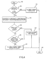
- Fig. 4 depicts the flowchart illustrating the operations associated with a method conforming to various aspects of the present invention to reduce the rate of change in luminance when the LED is ramping at low luminance, i.e., a variable slew rate control system that uses a configurable flare ceiling to determine when the PWM values (corresponding to the LED's luminance) should be modified from a rate of change that was previously determined by another method, such as by the linear contrast curve, and herein referred to as the "initial rate", to a slower and even-more-gradually decreasing rate of change based on how far the most recent PWM value is below the flare ceiling. While this embodiment illustrates how a particular luminance control methodology may be modified to reduce cliffs, the embodiment may be used to modify other luminance control methodologies regardless of the luminance operating region and allowed luminance change to reduce perceived cliffs produced by those methodologies.
- the embodiment begins in start mode 400. As the LED is ramped from on to off (or off to on), operation 405 is performed to determine if the most recent PWM value is below the flare ceiling. If not, operation 410 is performed where no adjustment to the initial rate (measured in PWM counts per tick) is necessary. Accordingly, in operation 410, the allowed change is set to the initial rate. The initial rate may be computed using the linear contrast curve or some other slew rate control methodology. Then operation 440 is executed and the process stops. However, if operation 405 determines that the most recent PWM value is below the flare ceiling, then operation 415 is performed.
- the distance below the flare ceiling i.e., "below ceiling” is computed in terms of PWM counts by subtracting the current PWM value from the flare ceiling.
- a slope adjustment directly proportional to the distance below the flare ceiling (that is, the further below the ceiling, the larger the slope adjustment and therefore the slower the resulting rate of change) is also computed by dividing below ceiling by a configurable flare adjustment factor. Note that a smaller flare adjustment factor slows the rate of change more quickly than a larger one.
- operation 420 is performed to determine if the initial rate is less than the slope adjustment. If so, then operation 425 is performed. Operation 425 sets the allowed change to a configurable minimum change per tick. Then operation 440 is performed and the process stops.
- operation 430 is performed to determine if the initial rate minus the slope adjustment is less than the minimum change per tick (use of a minimum change per tick that is greater than zero ensures that the final PWM value is reached). If operation 430 determines that the initial rate minus the slope adjustment is not less than the minimum change per tick, then operation 435 is performed. Operation 435 sets the allowed change to the initial rate minus the slope adjustment. Then operation 440 is performed and the process stops. If operation 430 determines that the initial rate minus the slope adjustment is less than the minimum change per tick, then operation 425 is performed to set the allowed change to the minimum change per tick. Then operation 440 is performed and the process stops.
- the flare ceiling is set to a PWM value of 10,000 for both ramp downs and ramp ups
- the flare adjustment factor is set to 28 for ramp downs and 32 for ramp ups
- the minimum change per tick is set to 22 for both ramp downs and ramp ups
- the configurable parameters are set to other values during design or are user selectable.
- Turning an LED on or off by following the linear contrast curve can also introduce a perceived cliff in LED brightness when the LED's luminance is ramping near its maximum luminance due to the steep slope of the linear contrast curve in that region.
- a perceived cliff in LED brightness when the LED's luminance is ramping near its maximum luminance due to the steep slope of the linear contrast curve in that region.
- a user may perceive that the LED "jumps" to its fully on brightness (this is the "cliff' effect).
- the point at which this cliff occurs varies with the user's sensitivity to such effects and the light reflecting off of the surrounding area, but typically occurs when the LED's 16-bit PWM value exceeds 50,000.
- Another embodiment of the present invention minimizes this top cliff in perceived brightness by introducing an allowed maximum PWM change per tick when the LED luminance is ramped to make the LED brighter or dimmer, or to turn the LED on or off.
- a slew rate control methodology based on the linear contrast curve may be used to compute a target PWM change per tick based on a target PWM value, a prior PWM value, and/or the number of PWM update ticks over which the luminance change is to occur.
- the target PWM change per tick is then compared with the allowed maximum PWM change per tick.
- the max PWM change per tick may be user selectable or selected by a designer at the time an embodiment is configured (i.e., is designer selectable), while in other embodiments it may be set by hardware or software to 400 or another fixed value.
- the lower of the two values is used to limit the change in duty cycle of the PWM generator's output at each tick to provide a less abrupt change in perceived brightness.
- this embodiment limits the change in PWM value to a predetermined value to minimize any perceived cliff in the brightness of the status indicator light as it is turned on or off.
- the status indicator light may also be pulsed to indicate that the electronic device is in a special power state such as a sleep state.
- a PWM generator to control LED brightness
- the pulsing of the LED on and off during sleep mode may be implemented with a "breathing curve" 500 as illustrated in Fig. 5 .
- the breathing curve generally has a pulse-like shape with a minimum breathing luminance (also called “dwell luminance") 505, an on luminance 510, a rise time 515, an on time 520, a fall time 525 and a dwell time 530.
- the breathing curve has a rise time of 1.7 seconds, an on time of 0.2 seconds, a fall time of 2.6 seconds and a dwell time of 0.5 seconds for an overall period of 5 seconds.
- Other implementations may have breathing curves with faster or slower rise and fall times, and shorter or longer on and dwell times.
- the breathing curve may indicate that the device is in a special power state, such as a sleep state, or may convey other information regarding the operation of a computing device or other device associated with the LED.
- An envelope function may be employed to scale the breathing curve 500 or any other luminance scaling or adjustment described herein, such as ramping down or ramping up the luminance of an LED.
- the instantaneous output of the envelope function which is multiplied times the value of the breathing curve or any other luminance scaling or adjustment described herein, is a fraction or decimal ranging from zero to one.
- Some embodiments may apply the envelope function to the breathing curve 500, or any portion thereof, to scale the curve in order to account for the brightness (or dimness) of a room or surrounding area, or to account for the time of day, and thus provide a more pleasing visual appearance, e.g., so that the LED does not appear to be too bright in dimly lit rooms or too dim in brightly lit rooms.
- a light sensor may sense the ambient light conditions. Some embodiments may use the light sensor to determine the ambient lighting and select the value of the envelope function accordingly, while other embodiments may select the value of the envelope function based on the time of day. Thus, the actual value of the envelope function may vary with the ambient light or time of day and so too may the breathing curve 500.
- the change may be implemented by ramping the LED brightness from the old dwell luminance to the new dwell luminance during a specified time interval which may be the dwell time 600 as depicted in Fig. 6 .
- a specified time interval which may be the dwell time 600 as depicted in Fig. 6 .
- the human eye is more sensitive to changes in an LED's brightness when the LED is dim compared to when the LED is bright.
- another embodiment of the present invention employs a 3-step piecewise linear curve to ramp the LED luminance from the current dwell luminance to the new dwell luminance.
- the embodiment slew-rate limits the LED luminance as it ramps from the current dwell luminance to the new dwell luminance during the dwell time.
- the overall effect of using the 3-step piecewise linear curve is to reduce the rate of change in LED luminance in regions where the eye is more sensitive to changes in luminance, and to perceptually smooth the start and end regions of the ramp.
- Fig. 7 depicts a 3-step piecewise linear curve 700 implemented by one embodiment.
- the curve 700 has a start segment 705, a middle segment 710 and an end segment 715. It also has a first break point 720 and a second break point 725.
- the middle segment has a higher slew rate limit, i.e., the slope of the segment is greater, than does the start or end segment to make the perceived change in brightness appear less abrupt.
- the requested change in dwell luminance which may be arbitrarily large, occurs during the dwell time.
- arbitrarily large it is meant that a requested magnitude change may be of virtually any size. Therefore, the ramp produced by the present embodiment may be (and generally is) constrained both in time and magnitude.
- the dwell time may be divided into three segments (start, middle and end).
- the user or designer can adjust the time duration for each segment (by specifying the break points) as well as the ratio of the step size (relative to the middle segment step size) of the start and end segments. That is, the user/designer can adjust the slope (PWM slew rate) of each segment to provide a breathing curve that appears most pleasing to the user/designer.
- Other implementations may fix the duration of the start segment, the duration of the end segment, the ratio of the middle to start segment step size, Q S , and the ratio of the middle to end segment step size, Q E .
- a system timer may be employed that generates 152 ticks per second and the dwell time may be 0.5 seconds or 76 timer ticks (T).
- T T S + T M + T E , where:
- T S , T E , Q S , and Q E may be fixed.
- V M the PWM step size in the middle segment.
- ⁇ T S * V M / Q S + T M * V M + T E * V M / Q E
- V M ⁇ / T M + T S / Q S + T E / Q E .
- V M may be calculated using integer division which truncates any fractional part of V M .
- 1 is added to V M .
- the total ramp in luminance may not occur completely within the dwell interval.
- each of these values may be separately tuned.
- the values may vary in a single embodiment between a ramping-up operation and a ramping-down operation. Accordingly, various embodiments of the present invention may embrace bi-directional tuning (i.e., tuning separately for ramp-ups and ramp-downs).
- the exemplary embodiment described above uses the 3-step piecewise linear curve method to produce a ramp that is constrained in both time and magnitude in the context of a dwell period of a breathing curve.
- Alternative embodiments, including any embodiment disclosed herein, may use the same 3-step piecewise linear curve method to produce a ramp that is constrained in both time and magnitude and is applied to any other context discussed herein or that requires such a ramp.
- an ambient light sensor may be used by the embodiment to monitor the ambient light conditions.
- a variety of solid state devices are available for the measurement of illumination.
- a TAOS TSL2561 device manufactured by Texas Advanced Optoelectronic Solutions of Plano, Texas, may be used to measure the ambient illumination.
- Alternative embodiments may use other light sensors.
- the light sensor measures the ambient light in the surrounding environment, such as a room, and generates a signal that represents the amount of measured light.
- the light sensor generally integrates the light collected over an integration time and outputs a measurement value when the integration time expires.
- the integration time may be set to one of several pre-determined values, and is set to 402 milliseconds in one embodiment of the present invention.
- the light sensor may output light measurement values based upon user or designer actions, such as pressing a button or setting a sample interval in a control panel.
- the light sensor alternatively may output a light measurement value when light or brightness changes in the surrounding environment exceed a predetermined threshold.
- a human user may perceive discontinuities in the LED's rate of change in brightness that occur due to a new ambient light level being reported by the system's ambient light sensor.
- the discontinuities are particularly noticeable (and thus undesirable) when the room's lighting is gradually increasing or decreasing such that the LED reaches its target brightness and holds there in less time than it takes to obtain the next ambient light reading.
- discontinuities can be smoothed by imposing a minimum time that should pass before the LED is allowed to reach a target brightness. In one embodiment this may be done by imposing a minimum number of timer ticks to target that is larger than the minimum number of timer ticks required to obtain the next ambient light sensor reading. Then, during a change in LED luminance, the LED will not plateau at its target luminance before a new light reading is available. Alternatively, a maximum step size (in terms ofPWM counts per timer tick) for a change in LED brightness can be imposed. By imposing such conditions, the LED's change in luminance is slew rate limited appropriately so that the human viewer typically perceives a smooth LED change in brightness over a wide variety of changing light conditions.
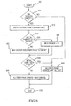
- Fig. 8 depicts a flowchart of the operations of one particular embodiment to implement a minimum ticks to target slew rate control methodology used to control the luminance of the LED status indicator when its target luminance changes in response to a change in ambient lighting or for any other reason.
- the methodology limits the allowed PWM change per timer tick that is used to update a PWM generator.
- the minimum ticks to target may be user selectable (or designer selectable) using a control panel in some embodiment or may be set by hardware or software to 70 or some other value in other embodiments.
- the minimum ticks to target should be set such that the time required to obtain a new ambient light reading is less than the following time: the minimum ticks to target times the time per tick.
- the flowchart of Fig. 8 may be performed when the ambient light sensor reading (or any other suitable control methodology) indicates that the LED's luminance should be changed.
- the embodiment begins in start mode 800 and assumes that a prior initial limit on the PWM's rate of change has already been established.
- the initial limit is an unconstrained value (i.e., it has not yet been constrained by this methodology) that may allow the LED luminance to plateau before the next ambient light sensor reading is available.
- the initial limit may be set by an operation or embodiment described herein, any operation or embodiment of Prouse, any other suitable control methodology, or any combination thereof.
- operation 805 is performed.
- operation 805 a check is performed to determine if the minimum ticks to target is greater than one. If not, operation 835 is performed.
- operation 835 the embodiment sets the allowed PWM change per tick to the initial limit. Once this is done, operation 845 is executed and the process stops.
- operation 805 determines that the minimum ticks to target is greater than 1, then operation 810 is performed.
- the embodiment computes the magnitude of the luminance change to be made (a delta to target) by taking the absolute value of the difference in the target PWM value and the current PWM value.
- delta to target
- operation 815 is performed.
- a check is performed to determine if the delta to target is less that two times the minimum ticks to target. If yes, then operation 820 is performed in which the maximum change is set to 1. Otherwise operation 825 is performed.
- operation 830 After operation 820 or operation 825 is executed, the embodiment performs operation 830.
- operation 830 a check is performed to determine if the initial limit is less than the maximum change. If so, then operation 835 is performed. Operation 835 sets the allowed PWM change per tick to the initial limit.
- operation 840 sets the allowed PWM change per tick to the maximum change. After operation 835 or operation 840, the embodiment executes operation 845 and the process stops.
- the allowed maximum change per tick is determined so that the target LED PWM value is not achieved before the next ambient light sensor reading by choosing the minimum ticks to target such that the minimum ticks to target times the time per tick is greater that the time required to obtain the next ambient light reading. If the delta to target is less than two times the minimum ticks to target, the maximum change is set to 1 (not zero) to make sure the target PWM value can eventually be achieved.
- FIG. 5 may depict a repetitive changing brightness pattern.
- one slew rate methodology could be applied only during the dwell time 530 (such as the methodology shown in Fig. 6 ), while other slew rate methodologies could be applied during the rise and fall times 515, 525, respectively.
- any of the embodiments herein may occur only during certain time periods and be inactive during other time periods.
- the methodologies of Figs. 4 and/or 8 may occur only between certain hours such as 8 p.m. and 7 a.m., or be time-bounded in any other manner.
Landscapes
- Circuit Arrangement For Electric Light Sources In General (AREA)
- Control Of Indicators Other Than Cathode Ray Tubes (AREA)
- Control Of El Displays (AREA)
Claims (8)
- Verfahren zum Variieren einer Luminanz eines Lichts (205), umfassend:Einstellen einer Ziel-Luminanz des Lichts (205); undVerändern der Luminanz des Lichts (205) von einer momentanen Luminanz zu der Ziel-Luminanz;wobei die Operation des Veränderns der Luminanz des Lichts (205) von der momentanen Luminanz zu der Ziel-Luminanz innerhalb einer festgelegten Zeit stattfindet,dadurch gekennzeichnet, dassdie festgelegte Zeit eine Verweilzeit (530) einer Atmungskurve (500) ist, wobei:die Verweilzeit (530) ein erstes Segment (705), ein zweites Segment (710) und ein drittes Segment (715) umfasst;die Luminanz sich von der momentanen Luminanz zu der Ziel-Luminanz ändert mit einer ersten Rate während des ersten Segments (705), einer zweiten Rate während des zweiten Segments (710) und einer dritten Rate während des dritten Segments (715), wobei die zweite Rate die erste und die dritte Rate überschreitet.
- Verfahren nach Anspruch 1, ferner umfassend:Bestimmen einer Umgebungshelligkeit; wobei die Operation des Einstellens einer Ziel-Luminanz des Lichts (205) auf der Umgebungshelligkeit basiert.
- Verfahren nach Anspruch 1, wobei das Licht (205) gewählt wird aus seiner Gruppe umfassend:eine Licht-emittierende Diode;eine Flüssigkristallanzeige;eine Kathodenstrahlröhrenvorrichtung; undeine Plasma-Anzeige.
- Verfahren nach Anspruch 1, ferner umfassend:Verändern der Luminanz des Lichts (205) von der Ziel-Luminanz zu einer hohen Luminanz;Beibehalten der hohen Luminanz für eine Zeitdauer; undVerändern der Luminanz des Lichts (205) von der hohen Luminanz zu der Ziel-Luminanz nach der Zeitdauer.
- Verfahren nach Anspruch 1, wobei mindestens die Operation des Veränderns der Luminanz des Lichts (205) von einer momentanen Luminanz zu der Ziel-Luminanz nur während einer bestimmten Tageszeit stattfindet.
- Verfahren nach Anspruch 1, wobei die Zeitdauer für mindestens eines der ersten, zweiten und dritten Segmente verschieden ist von mindestens einem anderen Segment.
- Verfahren nach Anspruch 1, ferner umfassend:Bestimmen einer minimalen Zeit zum Erreichen der Ziel-Luminanz;Einstellen einer minimalen Anzahl von Zeitgeber-Ticks, die notwendig sind, um die Luminanz von einer initialen Luminanz zu der Ziel-Luminanz zu ändern; undVerändern der Luminanz des Lichts von der initialen Luminanz zu der Ziel-Luminanz in einer Anzahl von Zeitgeber-Ticks, die mindestens gleich der minimalen Anzahl von Zeitgeber-Ticks ist.
- Vorrichtung (200), die betriebsfähig ist zum Ausführen des Verfahrens einem der vorstehenden Ansprüche.
Applications Claiming Priority (3)
| Application Number | Priority Date | Filing Date | Title |
|---|---|---|---|
| US11/558,376 US8373355B2 (en) | 2006-11-09 | 2006-11-09 | Brightness control of a status indicator light |
| EP07854483A EP2095688A2 (de) | 2006-11-09 | 2007-10-29 | Helligkeitsregelung einer statusindikatorlampe |
| PCT/US2007/082799 WO2008060842A2 (en) | 2006-11-09 | 2007-10-29 | Brightness control of a status indicator light |
Related Parent Applications (2)
| Application Number | Title | Priority Date | Filing Date |
|---|---|---|---|
| EP07854483.0 Division | 2007-10-29 | ||
| EP07854483A Division EP2095688A2 (de) | 2006-11-09 | 2007-10-29 | Helligkeitsregelung einer statusindikatorlampe |
Publications (3)
| Publication Number | Publication Date |
|---|---|
| EP2473004A1 EP2473004A1 (de) | 2012-07-04 |
| EP2473004B1 true EP2473004B1 (de) | 2015-04-29 |
| EP2473004B2 EP2473004B2 (de) | 2018-08-29 |
Family
ID=39153607
Family Applications (3)
| Application Number | Title | Priority Date | Filing Date |
|---|---|---|---|
| EP07854483A Withdrawn EP2095688A2 (de) | 2006-11-09 | 2007-10-29 | Helligkeitsregelung einer statusindikatorlampe |
| EP11190911.5A Not-in-force EP2473004B2 (de) | 2006-11-09 | 2007-10-29 | Helligkeitssteuerung einer Statusanzeigeleuchte |
| EP11190909.9A Withdrawn EP2437575A3 (de) | 2006-11-09 | 2007-10-29 | Helligkeitssteuerung einer Statusanzeigeleuchte |
Family Applications Before (1)
| Application Number | Title | Priority Date | Filing Date |
|---|---|---|---|
| EP07854483A Withdrawn EP2095688A2 (de) | 2006-11-09 | 2007-10-29 | Helligkeitsregelung einer statusindikatorlampe |
Family Applications After (1)
| Application Number | Title | Priority Date | Filing Date |
|---|---|---|---|
| EP11190909.9A Withdrawn EP2437575A3 (de) | 2006-11-09 | 2007-10-29 | Helligkeitssteuerung einer Statusanzeigeleuchte |
Country Status (5)
| Country | Link |
|---|---|
| US (4) | US8373355B2 (de) |
| EP (3) | EP2095688A2 (de) |
| CN (1) | CN101578917B (de) |
| TW (2) | TWI448206B (de) |
| WO (1) | WO2008060842A2 (de) |
Families Citing this family (57)
| Publication number | Priority date | Publication date | Assignee | Title |
|---|---|---|---|---|
| JP4316469B2 (ja) * | 2004-10-15 | 2009-08-19 | 株式会社東芝 | 自動設計装置 |
| US9086737B2 (en) * | 2006-06-15 | 2015-07-21 | Apple Inc. | Dynamically controlled keyboard |
| US8373355B2 (en) | 2006-11-09 | 2013-02-12 | Apple Inc. | Brightness control of a status indicator light |
| CN200990080Y (zh) * | 2006-12-15 | 2007-12-12 | 鸿富锦精密工业(深圳)有限公司 | 电源指示灯控制电路 |
| TW200905123A (en) * | 2007-07-30 | 2009-02-01 | Topco Technologies Corp | Light emitting diode lamp and illumination system |
| WO2009057527A1 (ja) * | 2007-11-01 | 2009-05-07 | Nec Corporation | 輝度制御方法および表示装置 |
| JP4501991B2 (ja) | 2007-11-13 | 2010-07-14 | 株式会社カシオ日立モバイルコミュニケーションズ | 端末装置及びプログラム |
| WO2009117015A1 (en) * | 2008-03-18 | 2009-09-24 | Shenzhen Tcl New Technology Ltd | Apparatus and method for managing the power of an electronic device |
| US7750282B2 (en) * | 2008-05-21 | 2010-07-06 | Apple Inc. | Dual purpose ambient light sensor |
| JP5240295B2 (ja) * | 2008-10-15 | 2013-07-17 | パナソニック株式会社 | 輝度補正装置及び輝度補正方法 |
| TWI479951B (zh) * | 2008-12-24 | 2015-04-01 | Novatek Microelectronics Corp | 光源裝置及其光源驅動電路 |
| TW201029515A (en) * | 2009-01-23 | 2010-08-01 | Wistron Corp | Electronic device, a control system and a method of controlling a light-emitting element thereof |
| GB0901810D0 (en) * | 2009-02-05 | 2009-03-11 | Marl Internat Ltd | Improvements in and relating to lighting systems for train units |
| US20100306683A1 (en) * | 2009-06-01 | 2010-12-02 | Apple Inc. | User interface behaviors for input device with individually controlled illuminated input elements |
| US8282261B2 (en) * | 2009-06-01 | 2012-10-09 | Apple, Inc. | White point adjustment for multicolor keyboard backlight |
| US9247611B2 (en) * | 2009-06-01 | 2016-01-26 | Apple Inc. | Light source with light sensor |
| US8378972B2 (en) * | 2009-06-01 | 2013-02-19 | Apple Inc. | Keyboard with increased control of backlit keys |
| US8138687B2 (en) * | 2009-06-30 | 2012-03-20 | Apple Inc. | Multicolor lighting system |
| US8339028B2 (en) | 2009-06-30 | 2012-12-25 | Apple Inc. | Multicolor light emitting diodes |
| US20110037704A1 (en) * | 2009-08-14 | 2011-02-17 | Allen Ku | Flash lighting input apparatus and driving method therefor |
| US8299729B2 (en) * | 2009-09-22 | 2012-10-30 | Infineon Technologies Austria Ag | System and method for non-linear dimming of a light source |
| US8340834B1 (en) * | 2010-04-16 | 2012-12-25 | Cooper Technologies Company | Occupancy sensor with energy usage indicator |
| CN101853633A (zh) * | 2010-04-30 | 2010-10-06 | 宇龙计算机通信科技(深圳)有限公司 | 一种在移动终端实现呼吸灯的方法及移动终端 |
| CN102242888A (zh) * | 2010-05-12 | 2011-11-16 | 鸿富锦精密工业(深圳)有限公司 | 发光装置及其发光强度调节方法 |
| US8400626B2 (en) | 2010-06-10 | 2013-03-19 | Apple Inc. | Ambient light sensor |
| US8451146B2 (en) | 2010-06-11 | 2013-05-28 | Apple Inc. | Legend highlighting |
| US8378857B2 (en) | 2010-07-19 | 2013-02-19 | Apple Inc. | Illumination of input device |
| US9275810B2 (en) | 2010-07-19 | 2016-03-01 | Apple Inc. | Keyboard illumination |
| CN101969483B (zh) * | 2010-08-02 | 2014-07-30 | 惠州Tcl移动通信有限公司 | 一种手机指示电路 |
| CN102724785A (zh) * | 2011-03-29 | 2012-10-10 | 鸿富锦精密工业(深圳)有限公司 | 控制电路 |
| US9094539B1 (en) * | 2011-09-22 | 2015-07-28 | Amazon Technologies, Inc. | Dynamic device adjustments based on determined user sleep state |
| CN103092122B (zh) * | 2011-11-03 | 2016-06-01 | 西门子公司 | 带有状态指示单元的设备和切换状态指示单元的活跃状态的方法 |
| CN102438369A (zh) * | 2011-11-07 | 2012-05-02 | 苏州三诺信息科技有限公司 | 通用型电脑睡眠状态电源灯渐暗功能的实现方法 |
| US8853952B2 (en) * | 2011-12-07 | 2014-10-07 | Jenesis International Incorporated | Light level and light level rate of change sensor |
| JP6041121B2 (ja) * | 2012-05-11 | 2016-12-07 | 日本精機株式会社 | 表示装置及びその制御方法 |
| JP2015531142A (ja) * | 2012-06-08 | 2015-10-29 | トムソン ライセンシングThomson Licensing | 装置内のインジケータ光源を制御する装置及び方法 |
| CN103857099A (zh) * | 2012-11-29 | 2014-06-11 | 深圳市海洋王照明工程有限公司 | 一种led调光电路 |
| US9307613B2 (en) | 2013-03-11 | 2016-04-05 | Lutron Electronics Co., Inc. | Load control device with an adjustable control curve |
| US9137862B2 (en) * | 2013-06-07 | 2015-09-15 | Texas Instruments Incorporated | Slew rate controlled transistor driver |
| US9113518B2 (en) * | 2013-07-11 | 2015-08-18 | Ellenby Technologies, Inc. | Battery powered light source for compartment illumination |
| CN103987159A (zh) * | 2014-04-14 | 2014-08-13 | 立锜科技股份有限公司 | 亮度调整方法 |
| US9826605B2 (en) * | 2014-04-18 | 2017-11-21 | Sanjaykumar J. Vora | Lighting control system and method |
| US20150305106A1 (en) * | 2014-04-18 | 2015-10-22 | Sanjaykumar J. Vora | Lighting Control System and Method |
| WO2016001065A1 (en) * | 2014-07-01 | 2016-01-07 | Koninklijke Philips N.V. | Led driver, lighting system using the driver and driving method |
| CN105988914A (zh) * | 2015-02-28 | 2016-10-05 | 联想(北京)有限公司 | 一种信息处理方法及电子设备 |
| US10004125B2 (en) * | 2015-05-22 | 2018-06-19 | Google Llc | Automatically adjust sensor sample rates and modes based on sensor feedback and system state |
| CA2996035A1 (en) * | 2015-08-25 | 2017-03-02 | Abl Ip Holding Llc | Enhancements for use of a display in a software configurable lighting device |
| JP2018144433A (ja) * | 2017-03-08 | 2018-09-20 | 東芝テック株式会社 | 発光輝度調整装置 |
| CN107172774B (zh) * | 2017-05-12 | 2019-02-19 | 广东欧谱曼迪科技有限公司 | 一种控制呼吸灯呼吸效果的方法 |
| TWI628547B (zh) * | 2017-05-25 | 2018-07-01 | 技嘉科技股份有限公司 | 擴充裝置 |
| WO2020051036A1 (en) * | 2018-09-05 | 2020-03-12 | The Gillette Company Llc | Modulating an illumination level of a user interface luminous element |
| AU2020226737A1 (en) * | 2019-02-21 | 2021-09-30 | Dialight Corporation | Lifi network and associated method |
| US10907288B1 (en) | 2019-09-27 | 2021-02-02 | Whirlpool Corporation | Household appliance with luminary communication interface |
| CN110933814A (zh) * | 2019-12-31 | 2020-03-27 | 大连海事大学 | 一种水下机器人的led照明灯自适应调节方法 |
| US11835382B2 (en) | 2021-03-02 | 2023-12-05 | Apple Inc. | Handheld electronic device |
| CN113326029B (zh) * | 2021-05-13 | 2024-03-22 | 深圳恒之源技术股份有限公司 | 一种led灯具亮度调节方法、系统及计算机可读存储介质 |
| TWI794947B (zh) * | 2021-08-26 | 2023-03-01 | 眾用車材製造股份有限公司 | 控制警示燈進入低電力模式之方法 |
Citations (3)
| Publication number | Priority date | Publication date | Assignee | Title |
|---|---|---|---|---|
| US5589741A (en) | 1993-04-22 | 1996-12-31 | Research Foundation For Mental Hygiene, Inc. | System for creating naturalistic illumination cycles |
| WO2001099475A1 (en) | 2000-06-21 | 2001-12-27 | Color Kinetics Incorporated | Method and apparatus for controlling a lighting system in response to an audio input |
| WO2005069699A1 (en) | 2004-01-07 | 2005-07-28 | Lutron Electronics Co., Inc. | Lighting control device having improved long fade off |
Family Cites Families (59)
| Publication number | Priority date | Publication date | Assignee | Title |
|---|---|---|---|---|
| DE3535749A1 (de) * | 1985-04-12 | 1986-10-16 | Fa. Carl Zeiss, 7920 Heidenheim | Einrichtung zur helligkeitsregelung in mikroskopen |
| US4769753A (en) * | 1987-07-02 | 1988-09-06 | Minnesota Mining And Manufacturing Company | Compensated exponential voltage multiplier for electroluminescent displays |
| US5223814A (en) * | 1988-12-05 | 1993-06-29 | Prince Corporation | Sensor for vehicle accessories |
| JPH0775196B2 (ja) | 1991-03-28 | 1995-08-09 | 松下電工株式会社 | 調光制御装置 |
| JPH04324294A (ja) | 1991-04-24 | 1992-11-13 | Matsushita Electric Works Ltd | 光放射電子管点灯装置 |
| JP3060697B2 (ja) | 1992-02-26 | 2000-07-10 | トヨタ自動車株式会社 | 車両用ルームランプ消灯制御装置 |
| US5497181A (en) * | 1992-06-29 | 1996-03-05 | Xerox Corporation | Dynamic control of individual spot exposure in an optical output device |
| JP3304156B2 (ja) | 1993-02-22 | 2002-07-22 | 松下電工株式会社 | 放電灯点灯装置 |
| JP2753436B2 (ja) | 1993-05-06 | 1998-05-20 | 富士通テン株式会社 | 発光表示の輝度調整方法、および、輝度調整機能付き画像表示装置 |
| JPH0714694A (ja) | 1993-06-16 | 1995-01-17 | Hitachi Lighting Ltd | 放電灯調光装置 |
| US6271825B1 (en) * | 1996-04-23 | 2001-08-07 | Rainbow Displays, Inc. | Correction methods for brightness in electronic display |
| JPH1073865A (ja) | 1996-08-30 | 1998-03-17 | Moritex Corp | 光源用電源装置 |
| US6147664A (en) * | 1997-08-29 | 2000-11-14 | Candescent Technologies Corporation | Controlling the brightness of an FED device using PWM on the row side and AM on the column side |
| US6095661A (en) * | 1998-03-19 | 2000-08-01 | Ppt Vision, Inc. | Method and apparatus for an L.E.D. flashlight |
| JP2000098942A (ja) | 1998-09-23 | 2000-04-07 | Reiko Harada | 電飾看板 |
| CA2354018A1 (en) * | 1998-12-14 | 2000-06-22 | Alan Richard | Portable microdisplay system |
| CN1209742C (zh) * | 2000-06-15 | 2005-07-06 | 夏普株式会社 | 液晶显示装置、照明装置和照明装置的驱动方法 |
| TW544650B (en) * | 2000-12-27 | 2003-08-01 | Matsushita Electric Ind Co Ltd | Matrix-type display device and driving method thereof |
| JP2002311996A (ja) * | 2001-02-09 | 2002-10-25 | Sony Corp | コンテンツ供給システム |
| JP3681121B2 (ja) * | 2001-06-15 | 2005-08-10 | キヤノン株式会社 | 駆動回路及び表示装置 |
| US7008090B2 (en) * | 2001-08-30 | 2006-03-07 | Donnelly Corporation | Vehicle mirror system with light conduiting member |
| US6720743B2 (en) * | 2001-09-28 | 2004-04-13 | Matsushita Electric Industrial Co., Ltd. | Lighting system |
| JP3674568B2 (ja) * | 2001-10-02 | 2005-07-20 | ソニー株式会社 | 強度変調方法及びシステム並びに光量変調装置 |
| EP1345428A3 (de) * | 2002-03-11 | 2005-03-16 | Sony Corporation | Verfahren und System zur optischen Intensitätsmodulation, und Apparat zur Modulation des optischen Zustandes |
| US6841947B2 (en) * | 2002-05-14 | 2005-01-11 | Garmin At, Inc. | Systems and methods for controlling brightness of an avionics display |
| US7769353B2 (en) * | 2002-05-30 | 2010-08-03 | Motorola, Inc. | Mobile communication device including an extended array sensor |
| US20040017158A1 (en) * | 2002-07-26 | 2004-01-29 | Svt Technologies Private Limited, | Smart dimmer switch for maintaining constant luminance in a lighting environment |
| US6769772B2 (en) * | 2002-10-11 | 2004-08-03 | Eastman Kodak Company | Six color display apparatus having increased color gamut |
| US7236154B1 (en) * | 2002-12-24 | 2007-06-26 | Apple Inc. | Computer light adjustment |
| WO2004090997A1 (ja) * | 2003-04-01 | 2004-10-21 | Hunet Inc. | Led駆動装置及びled駆動方法 |
| JP2004309509A (ja) * | 2003-04-01 | 2004-11-04 | Hunet Inc | 表示装置の調整方法 |
| US7109465B2 (en) * | 2003-04-04 | 2006-09-19 | Avago Technologies Ecbu Ip (Singapore) Pte., Ltd. | System and method for converting ambient light energy into a digitized electrical output signal for controlling display and keypad illumination on a battery powered system |
| JP4030471B2 (ja) * | 2003-06-06 | 2008-01-09 | 日本テキサス・インスツルメンツ株式会社 | パルス信号生成回路 |
| JP4160458B2 (ja) | 2003-07-08 | 2008-10-01 | 矢崎総業株式会社 | Led駆動回路 |
| JP4180018B2 (ja) * | 2003-11-07 | 2008-11-12 | 三洋電機株式会社 | 画素回路及び表示装置 |
| US7477228B2 (en) * | 2003-12-22 | 2009-01-13 | Intel Corporation | Method and apparatus for characterizing and/or predicting display backlight response latency |
| US7126290B2 (en) * | 2004-02-02 | 2006-10-24 | Radiant Power Corp. | Light dimmer for LED and incandescent lamps |
| US7468722B2 (en) * | 2004-02-09 | 2008-12-23 | Microsemi Corporation | Method and apparatus to control display brightness with ambient light correction |
| JP4772336B2 (ja) * | 2004-02-27 | 2011-09-14 | ローム株式会社 | 駆動制御回路 |
| JP4748946B2 (ja) | 2004-03-31 | 2011-08-17 | 三菱電機株式会社 | 照明制御装置、照明装置、照明制御システム及び照明システム |
| US7835164B2 (en) * | 2004-04-28 | 2010-11-16 | Intersil Americas Inc. | Apparatus and method of employing combined switching and PWM dimming signals to control brightness of cold cathode fluorescent lamps used to backlight liquid crystal displays |
| US8358262B2 (en) * | 2004-06-30 | 2013-01-22 | Intel Corporation | Method and apparatus to synchronize backlight intensity changes with image luminance changes |
| WO2006006537A1 (ja) * | 2004-07-12 | 2006-01-19 | Sony Corporation | バックライトユニットの駆動装置及びその駆動方法 |
| JP2006041043A (ja) | 2004-07-23 | 2006-02-09 | Sanyo Electric Co Ltd | Led駆動回路 |
| JP4694801B2 (ja) * | 2004-08-11 | 2011-06-08 | 三洋電機株式会社 | Led制御回路 |
| JP4320651B2 (ja) * | 2004-10-08 | 2009-08-26 | ソニー株式会社 | Led駆動装置、発光量制御方法 |
| EP1662477A1 (de) * | 2004-11-26 | 2006-05-31 | Barco N.V. | Test oder Kalibrierung angezeigter Graustufen |
| US7615938B2 (en) | 2005-04-06 | 2009-11-10 | Apple Inc. | Method and system for variable LED output in an electronic device |
| JP2006303002A (ja) * | 2005-04-18 | 2006-11-02 | Toshiba Corp | 情報処理装置および輝度調整方法 |
| US7501960B2 (en) * | 2005-10-20 | 2009-03-10 | Dell Products L.P. | Control of indicator lights in portable information handling system using ambient light sensors |
| CN101026918A (zh) * | 2006-02-21 | 2007-08-29 | 马士科技有限公司 | 紧凑型光控荧光灯及其光控电路 |
| WO2007102633A1 (en) | 2006-03-08 | 2007-09-13 | Attocon Co., Ltd. | Light guide film comprising reflecting layer and emitting keypad having the same |
| US20080078921A1 (en) * | 2006-08-25 | 2008-04-03 | Motorola, Inc. | Multiple light sensors and algorithms for luminance control of mobile display devices |
| US8373355B2 (en) | 2006-11-09 | 2013-02-12 | Apple Inc. | Brightness control of a status indicator light |
| US7446303B2 (en) * | 2007-01-31 | 2008-11-04 | Avago Technologies Ecbu Ip (Singapore) Pte. Ltd | Ambient light sensing using a color sensor |
| KR100870113B1 (ko) | 2007-04-04 | 2008-11-25 | 아이비컴(주) | 유기발광소자를 이용한 휴대폰 키패드백라이트 |
| CN201185147Y (zh) | 2008-02-02 | 2009-01-21 | 精模电子科技(深圳)有限公司 | 背光键盘 |
| US7750282B2 (en) * | 2008-05-21 | 2010-07-06 | Apple Inc. | Dual purpose ambient light sensor |
| US8400626B2 (en) * | 2010-06-10 | 2013-03-19 | Apple Inc. | Ambient light sensor |
-
2006
- 2006-11-09 US US11/558,376 patent/US8373355B2/en active Active
-
2007
- 2007-10-29 EP EP07854483A patent/EP2095688A2/de not_active Withdrawn
- 2007-10-29 WO PCT/US2007/082799 patent/WO2008060842A2/en active Application Filing
- 2007-10-29 CN CN2007800495214A patent/CN101578917B/zh not_active Expired - Fee Related
- 2007-10-29 EP EP11190911.5A patent/EP2473004B2/de not_active Not-in-force
- 2007-10-29 EP EP11190909.9A patent/EP2437575A3/de not_active Withdrawn
- 2007-11-09 TW TW096142597A patent/TWI448206B/zh not_active IP Right Cessation
- 2007-11-09 TW TW102107088A patent/TWI457052B/zh not_active IP Right Cessation
-
2010
- 2010-06-21 US US12/819,351 patent/US8653745B2/en active Active
- 2010-06-21 US US12/819,376 patent/US8610367B2/en active Active
-
2013
- 2013-12-17 US US14/109,720 patent/US9144132B2/en not_active Expired - Fee Related
Patent Citations (3)
| Publication number | Priority date | Publication date | Assignee | Title |
|---|---|---|---|---|
| US5589741A (en) | 1993-04-22 | 1996-12-31 | Research Foundation For Mental Hygiene, Inc. | System for creating naturalistic illumination cycles |
| WO2001099475A1 (en) | 2000-06-21 | 2001-12-27 | Color Kinetics Incorporated | Method and apparatus for controlling a lighting system in response to an audio input |
| WO2005069699A1 (en) | 2004-01-07 | 2005-07-28 | Lutron Electronics Co., Inc. | Lighting control device having improved long fade off |
Also Published As
| Publication number | Publication date |
|---|---|
| CN101578917A (zh) | 2009-11-11 |
| US20100253239A1 (en) | 2010-10-07 |
| EP2095688A2 (de) | 2009-09-02 |
| EP2437575A3 (de) | 2015-12-09 |
| TW201325319A (zh) | 2013-06-16 |
| TWI457052B (zh) | 2014-10-11 |
| US20100253228A1 (en) | 2010-10-07 |
| TWI448206B (zh) | 2014-08-01 |
| WO2008060842A2 (en) | 2008-05-22 |
| US20140103831A1 (en) | 2014-04-17 |
| WO2008060842A3 (en) | 2008-12-11 |
| US20080111500A1 (en) | 2008-05-15 |
| US8373355B2 (en) | 2013-02-12 |
| CN101578917B (zh) | 2013-09-11 |
| EP2473004B2 (de) | 2018-08-29 |
| US9144132B2 (en) | 2015-09-22 |
| US8653745B2 (en) | 2014-02-18 |
| TW200835392A (en) | 2008-08-16 |
| EP2473004A1 (de) | 2012-07-04 |
| EP2437575A2 (de) | 2012-04-04 |
| US8610367B2 (en) | 2013-12-17 |
Similar Documents
| Publication | Publication Date | Title |
|---|---|---|
| EP2473004B1 (de) | Helligkeitssteuerung einer Statusanzeigeleuchte | |
| JP5085846B2 (ja) | 調整可能なバックライトを用いてフラットパネルディスプレイ装置を照光する方法及び装置 | |
| US6388388B1 (en) | Brightness control system and method for a backlight display device using backlight efficiency | |
| US8223117B2 (en) | Method and apparatus to control display brightness with ambient light correction | |
| US20040012556A1 (en) | Method and related device for controlling illumination of a backlight of a liquid crystal display | |
| JP2008077862A (ja) | 調光回路 | |
| EP1723629A1 (de) | Umgebungslichtsensor | |
| EP2785146A1 (de) | Steuersignalerzeugungsvorrichtung und Audiosignalverarbeitungsvorrichtung | |
| US7615938B2 (en) | Method and system for variable LED output in an electronic device | |
| JP2007095635A (ja) | 表示ディスプレイにおける照明装置の調光制御を行う方法及び装置 | |
| EP2571334B1 (de) | LED-Beleuchtungszeit-Steuervorrichtung | |
| JP2011040227A (ja) | 照明装置、照明システム及び照明装置の制御方法 | |
| JP2002311925A (ja) | 画像表示装置 | |
| JP2001250697A (ja) | 照明装置 | |
| US10699656B2 (en) | Luminance adjustment device, display device and luminance adjustment method | |
| JP5938697B2 (ja) | 調光装置、点灯制御装置、調光方法 | |
| JP2007232868A (ja) | 表示装置および表示方法 |
Legal Events
| Date | Code | Title | Description |
|---|---|---|---|
| 17P | Request for examination filed |
Effective date: 20111228 |
|
| AC | Divisional application: reference to earlier application |
Ref document number: 2095688 Country of ref document: EP Kind code of ref document: P |
|
| AK | Designated contracting states |
Kind code of ref document: A1 Designated state(s): AT BE BG CH CY CZ DE DK EE ES FI FR GB GR HU IE IS IT LI LT LU LV MC MT NL PL PT RO SE SI SK TR |
|
| AX | Request for extension of the european patent |
Extension state: AL BA HR MK RS |
|
| PUAI | Public reference made under article 153(3) epc to a published international application that has entered the european phase |
Free format text: ORIGINAL CODE: 0009012 |
|
| 17Q | First examination report despatched |
Effective date: 20131010 |
|
| GRAP | Despatch of communication of intention to grant a patent |
Free format text: ORIGINAL CODE: EPIDOSNIGR1 |
|
| INTG | Intention to grant announced |
Effective date: 20141112 |
|
| GRAS | Grant fee paid |
Free format text: ORIGINAL CODE: EPIDOSNIGR3 |
|
| GRAA | (expected) grant |
Free format text: ORIGINAL CODE: 0009210 |
|
| AC | Divisional application: reference to earlier application |
Ref document number: 2095688 Country of ref document: EP Kind code of ref document: P |
|
| AK | Designated contracting states |
Kind code of ref document: B1 Designated state(s): AT BE BG CH CY CZ DE DK EE ES FI FR GB GR HU IE IS IT LI LT LU LV MC MT NL PL PT RO SE SI SK TR |
|
| REG | Reference to a national code |
Ref country code: GB Ref legal event code: FG4D |
|
| REG | Reference to a national code |
Ref country code: CH Ref legal event code: EP |
|
| REG | Reference to a national code |
Ref country code: AT Ref legal event code: REF Ref document number: 725038 Country of ref document: AT Kind code of ref document: T Effective date: 20150515 |
|
| REG | Reference to a national code |
Ref country code: IE Ref legal event code: FG4D |
|
| REG | Reference to a national code |
Ref country code: DE Ref legal event code: R096 Ref document number: 602007041298 Country of ref document: DE Effective date: 20150611 |
|
| REG | Reference to a national code |
Ref country code: NL Ref legal event code: VDEP Effective date: 20150429 |
|
| REG | Reference to a national code |
Ref country code: AT Ref legal event code: MK05 Ref document number: 725038 Country of ref document: AT Kind code of ref document: T Effective date: 20150429 |
|
| REG | Reference to a national code |
Ref country code: LT Ref legal event code: MG4D |
|
| PG25 | Lapsed in a contracting state [announced via postgrant information from national office to epo] |
Ref country code: NL Free format text: LAPSE BECAUSE OF FAILURE TO SUBMIT A TRANSLATION OF THE DESCRIPTION OR TO PAY THE FEE WITHIN THE PRESCRIBED TIME-LIMIT Effective date: 20150429 |
|
| PG25 | Lapsed in a contracting state [announced via postgrant information from national office to epo] |
Ref country code: FI Free format text: LAPSE BECAUSE OF FAILURE TO SUBMIT A TRANSLATION OF THE DESCRIPTION OR TO PAY THE FEE WITHIN THE PRESCRIBED TIME-LIMIT Effective date: 20150429 Ref country code: LT Free format text: LAPSE BECAUSE OF FAILURE TO SUBMIT A TRANSLATION OF THE DESCRIPTION OR TO PAY THE FEE WITHIN THE PRESCRIBED TIME-LIMIT Effective date: 20150429 Ref country code: PT Free format text: LAPSE BECAUSE OF FAILURE TO SUBMIT A TRANSLATION OF THE DESCRIPTION OR TO PAY THE FEE WITHIN THE PRESCRIBED TIME-LIMIT Effective date: 20150831 Ref country code: ES Free format text: LAPSE BECAUSE OF FAILURE TO SUBMIT A TRANSLATION OF THE DESCRIPTION OR TO PAY THE FEE WITHIN THE PRESCRIBED TIME-LIMIT Effective date: 20150429 |
|
| PG25 | Lapsed in a contracting state [announced via postgrant information from national office to epo] |
Ref country code: IS Free format text: LAPSE BECAUSE OF FAILURE TO SUBMIT A TRANSLATION OF THE DESCRIPTION OR TO PAY THE FEE WITHIN THE PRESCRIBED TIME-LIMIT Effective date: 20150829 Ref country code: LV Free format text: LAPSE BECAUSE OF FAILURE TO SUBMIT A TRANSLATION OF THE DESCRIPTION OR TO PAY THE FEE WITHIN THE PRESCRIBED TIME-LIMIT Effective date: 20150429 Ref country code: GR Free format text: LAPSE BECAUSE OF FAILURE TO SUBMIT A TRANSLATION OF THE DESCRIPTION OR TO PAY THE FEE WITHIN THE PRESCRIBED TIME-LIMIT Effective date: 20150730 Ref country code: AT Free format text: LAPSE BECAUSE OF FAILURE TO SUBMIT A TRANSLATION OF THE DESCRIPTION OR TO PAY THE FEE WITHIN THE PRESCRIBED TIME-LIMIT Effective date: 20150429 |
|
| PG25 | Lapsed in a contracting state [announced via postgrant information from national office to epo] |
Ref country code: DK Free format text: LAPSE BECAUSE OF FAILURE TO SUBMIT A TRANSLATION OF THE DESCRIPTION OR TO PAY THE FEE WITHIN THE PRESCRIBED TIME-LIMIT Effective date: 20150429 Ref country code: EE Free format text: LAPSE BECAUSE OF FAILURE TO SUBMIT A TRANSLATION OF THE DESCRIPTION OR TO PAY THE FEE WITHIN THE PRESCRIBED TIME-LIMIT Effective date: 20150429 |
|
| REG | Reference to a national code |
Ref country code: DE Ref legal event code: R026 Ref document number: 602007041298 Country of ref document: DE |
|
| PLBI | Opposition filed |
Free format text: ORIGINAL CODE: 0009260 |
|
| PG25 | Lapsed in a contracting state [announced via postgrant information from national office to epo] |
Ref country code: PL Free format text: LAPSE BECAUSE OF FAILURE TO SUBMIT A TRANSLATION OF THE DESCRIPTION OR TO PAY THE FEE WITHIN THE PRESCRIBED TIME-LIMIT Effective date: 20150429 Ref country code: SK Free format text: LAPSE BECAUSE OF FAILURE TO SUBMIT A TRANSLATION OF THE DESCRIPTION OR TO PAY THE FEE WITHIN THE PRESCRIBED TIME-LIMIT Effective date: 20150429 Ref country code: RO Free format text: LAPSE BECAUSE OF NON-PAYMENT OF DUE FEES Effective date: 20150429 Ref country code: CZ Free format text: LAPSE BECAUSE OF FAILURE TO SUBMIT A TRANSLATION OF THE DESCRIPTION OR TO PAY THE FEE WITHIN THE PRESCRIBED TIME-LIMIT Effective date: 20150429 |
|
| PLAX | Notice of opposition and request to file observation + time limit sent |
Free format text: ORIGINAL CODE: EPIDOSNOBS2 |
|
| 26 | Opposition filed |
Opponent name: HELVAR OY AB Effective date: 20160129 |
|
| PG25 | Lapsed in a contracting state [announced via postgrant information from national office to epo] |
Ref country code: IT Free format text: LAPSE BECAUSE OF FAILURE TO SUBMIT A TRANSLATION OF THE DESCRIPTION OR TO PAY THE FEE WITHIN THE PRESCRIBED TIME-LIMIT Effective date: 20150429 |
|
| PG25 | Lapsed in a contracting state [announced via postgrant information from national office to epo] |
Ref country code: SI Free format text: LAPSE BECAUSE OF FAILURE TO SUBMIT A TRANSLATION OF THE DESCRIPTION OR TO PAY THE FEE WITHIN THE PRESCRIBED TIME-LIMIT Effective date: 20150429 Ref country code: LU Free format text: LAPSE BECAUSE OF FAILURE TO SUBMIT A TRANSLATION OF THE DESCRIPTION OR TO PAY THE FEE WITHIN THE PRESCRIBED TIME-LIMIT Effective date: 20151029 |
|
| REG | Reference to a national code |
Ref country code: CH Ref legal event code: PL |
|
| PG25 | Lapsed in a contracting state [announced via postgrant information from national office to epo] |
Ref country code: MC Free format text: LAPSE BECAUSE OF FAILURE TO SUBMIT A TRANSLATION OF THE DESCRIPTION OR TO PAY THE FEE WITHIN THE PRESCRIBED TIME-LIMIT Effective date: 20150429 |
|
| PLBB | Reply of patent proprietor to notice(s) of opposition received |
Free format text: ORIGINAL CODE: EPIDOSNOBS3 |
|
| REG | Reference to a national code |
Ref country code: IE Ref legal event code: MM4A |
|
| PG25 | Lapsed in a contracting state [announced via postgrant information from national office to epo] |
Ref country code: LI Free format text: LAPSE BECAUSE OF NON-PAYMENT OF DUE FEES Effective date: 20151031 Ref country code: CH Free format text: LAPSE BECAUSE OF NON-PAYMENT OF DUE FEES Effective date: 20151031 |
|
| REG | Reference to a national code |
Ref country code: FR Ref legal event code: ST Effective date: 20160630 |
|
| PG25 | Lapsed in a contracting state [announced via postgrant information from national office to epo] |
Ref country code: BE Free format text: LAPSE BECAUSE OF FAILURE TO SUBMIT A TRANSLATION OF THE DESCRIPTION OR TO PAY THE FEE WITHIN THE PRESCRIBED TIME-LIMIT Effective date: 20150429 Ref country code: FR Free format text: LAPSE BECAUSE OF NON-PAYMENT OF DUE FEES Effective date: 20151102 |
|
| PG25 | Lapsed in a contracting state [announced via postgrant information from national office to epo] |
Ref country code: IE Free format text: LAPSE BECAUSE OF NON-PAYMENT OF DUE FEES Effective date: 20151029 |
|
| PG25 | Lapsed in a contracting state [announced via postgrant information from national office to epo] |
Ref country code: BG Free format text: LAPSE BECAUSE OF FAILURE TO SUBMIT A TRANSLATION OF THE DESCRIPTION OR TO PAY THE FEE WITHIN THE PRESCRIBED TIME-LIMIT Effective date: 20150429 Ref country code: HU Free format text: LAPSE BECAUSE OF FAILURE TO SUBMIT A TRANSLATION OF THE DESCRIPTION OR TO PAY THE FEE WITHIN THE PRESCRIBED TIME-LIMIT; INVALID AB INITIO Effective date: 20071029 |
|
| PG25 | Lapsed in a contracting state [announced via postgrant information from national office to epo] |
Ref country code: CY Free format text: LAPSE BECAUSE OF FAILURE TO SUBMIT A TRANSLATION OF THE DESCRIPTION OR TO PAY THE FEE WITHIN THE PRESCRIBED TIME-LIMIT Effective date: 20150429 Ref country code: SE Free format text: LAPSE BECAUSE OF FAILURE TO SUBMIT A TRANSLATION OF THE DESCRIPTION OR TO PAY THE FEE WITHIN THE PRESCRIBED TIME-LIMIT Effective date: 20150429 |
|
| PG25 | Lapsed in a contracting state [announced via postgrant information from national office to epo] |
Ref country code: TR Free format text: LAPSE BECAUSE OF FAILURE TO SUBMIT A TRANSLATION OF THE DESCRIPTION OR TO PAY THE FEE WITHIN THE PRESCRIBED TIME-LIMIT Effective date: 20150429 Ref country code: MT Free format text: LAPSE BECAUSE OF FAILURE TO SUBMIT A TRANSLATION OF THE DESCRIPTION OR TO PAY THE FEE WITHIN THE PRESCRIBED TIME-LIMIT Effective date: 20150429 |
|
| PUAH | Patent maintained in amended form |
Free format text: ORIGINAL CODE: 0009272 |
|
| STAA | Information on the status of an ep patent application or granted ep patent |
Free format text: STATUS: PATENT MAINTAINED AS AMENDED |
|
| RAP2 | Party data changed (patent owner data changed or rights of a patent transferred) |
Owner name: APPLE INC. |
|
| 27A | Patent maintained in amended form |
Effective date: 20180829 |
|
| AK | Designated contracting states |
Kind code of ref document: B2 Designated state(s): AT BE BG CH CY CZ DE DK EE ES FI FR GB GR HU IE IS IT LI LT LU LV MC MT NL PL PT RO SE SI SK TR |
|
| REG | Reference to a national code |
Ref country code: DE Ref legal event code: R102 Ref document number: 602007041298 Country of ref document: DE |
|
| REG | Reference to a national code |
Ref country code: DE Ref legal event code: R079 Ref document number: 602007041298 Country of ref document: DE Free format text: PREVIOUS MAIN CLASS: H05B0033080000 Ipc: H05B0045000000 |
|
| PGFP | Annual fee paid to national office [announced via postgrant information from national office to epo] |
Ref country code: GB Payment date: 20210922 Year of fee payment: 15 |
|
| PGFP | Annual fee paid to national office [announced via postgrant information from national office to epo] |
Ref country code: DE Payment date: 20210923 Year of fee payment: 15 |
|
| REG | Reference to a national code |
Ref country code: DE Ref legal event code: R119 Ref document number: 602007041298 Country of ref document: DE |
|
| GBPC | Gb: european patent ceased through non-payment of renewal fee |
Effective date: 20221029 |
|
| PG25 | Lapsed in a contracting state [announced via postgrant information from national office to epo] |
Ref country code: DE Free format text: LAPSE BECAUSE OF NON-PAYMENT OF DUE FEES Effective date: 20230503 |
|
| PG25 | Lapsed in a contracting state [announced via postgrant information from national office to epo] |
Ref country code: GB Free format text: LAPSE BECAUSE OF NON-PAYMENT OF DUE FEES Effective date: 20221029 |