EP2472337A2 - Bilderzeugungsvorrichtung - Google Patents
Bilderzeugungsvorrichtung Download PDFInfo
- Publication number
- EP2472337A2 EP2472337A2 EP11194952A EP11194952A EP2472337A2 EP 2472337 A2 EP2472337 A2 EP 2472337A2 EP 11194952 A EP11194952 A EP 11194952A EP 11194952 A EP11194952 A EP 11194952A EP 2472337 A2 EP2472337 A2 EP 2472337A2
- Authority
- EP
- European Patent Office
- Prior art keywords
- waste toner
- unit
- fuser
- forming apparatus
- image forming
- Prior art date
- Legal status (The legal status is an assumption and is not a legal conclusion. Google has not performed a legal analysis and makes no representation as to the accuracy of the status listed.)
- Granted
Links
Images


Classifications
-
- G—PHYSICS
- G03—PHOTOGRAPHY; CINEMATOGRAPHY; ANALOGOUS TECHNIQUES USING WAVES OTHER THAN OPTICAL WAVES; ELECTROGRAPHY; HOLOGRAPHY
- G03G—ELECTROGRAPHY; ELECTROPHOTOGRAPHY; MAGNETOGRAPHY
- G03G21/00—Arrangements not provided for by groups G03G13/00 - G03G19/00, e.g. cleaning, elimination of residual charge
- G03G21/10—Collecting or recycling waste developer
- G03G21/105—Arrangements for conveying toner waste
-
- G—PHYSICS
- G03—PHOTOGRAPHY; CINEMATOGRAPHY; ANALOGOUS TECHNIQUES USING WAVES OTHER THAN OPTICAL WAVES; ELECTROGRAPHY; HOLOGRAPHY
- G03G—ELECTROGRAPHY; ELECTROPHOTOGRAPHY; MAGNETOGRAPHY
- G03G15/00—Apparatus for electrographic processes using a charge pattern
- G03G15/20—Apparatus for electrographic processes using a charge pattern for fixing, e.g. by using heat
- G03G15/2003—Apparatus for electrographic processes using a charge pattern for fixing, e.g. by using heat using heat
- G03G15/2014—Apparatus for electrographic processes using a charge pattern for fixing, e.g. by using heat using heat using contact heat
- G03G15/2017—Structural details of the fixing unit in general, e.g. cooling means, heat shielding means
-
- G—PHYSICS
- G03—PHOTOGRAPHY; CINEMATOGRAPHY; ANALOGOUS TECHNIQUES USING WAVES OTHER THAN OPTICAL WAVES; ELECTROGRAPHY; HOLOGRAPHY
- G03G—ELECTROGRAPHY; ELECTROPHOTOGRAPHY; MAGNETOGRAPHY
- G03G21/00—Arrangements not provided for by groups G03G13/00 - G03G19/00, e.g. cleaning, elimination of residual charge
- G03G21/10—Collecting or recycling waste developer
-
- G—PHYSICS
- G03—PHOTOGRAPHY; CINEMATOGRAPHY; ANALOGOUS TECHNIQUES USING WAVES OTHER THAN OPTICAL WAVES; ELECTROGRAPHY; HOLOGRAPHY
- G03G—ELECTROGRAPHY; ELECTROPHOTOGRAPHY; MAGNETOGRAPHY
- G03G21/00—Arrangements not provided for by groups G03G13/00 - G03G19/00, e.g. cleaning, elimination of residual charge
- G03G21/10—Collecting or recycling waste developer
- G03G21/12—Toner waste containers
-
- G—PHYSICS
- G03—PHOTOGRAPHY; CINEMATOGRAPHY; ANALOGOUS TECHNIQUES USING WAVES OTHER THAN OPTICAL WAVES; ELECTROGRAPHY; HOLOGRAPHY
- G03G—ELECTROGRAPHY; ELECTROPHOTOGRAPHY; MAGNETOGRAPHY
- G03G15/00—Apparatus for electrographic processes using a charge pattern
- G03G15/65—Apparatus which relate to the handling of copy material
- G03G15/6555—Handling of sheet copy material taking place in a specific part of the copy material feeding path
- G03G15/657—Feeding path after the transfer point and up to the fixing point, e.g. guides and feeding means for handling copy material carrying an unfused toner image
-
- G—PHYSICS
- G03—PHOTOGRAPHY; CINEMATOGRAPHY; ANALOGOUS TECHNIQUES USING WAVES OTHER THAN OPTICAL WAVES; ELECTROGRAPHY; HOLOGRAPHY
- G03G—ELECTROGRAPHY; ELECTROPHOTOGRAPHY; MAGNETOGRAPHY
- G03G2221/00—Processes not provided for by group G03G2215/00, e.g. cleaning or residual charge elimination
- G03G2221/16—Mechanical means for facilitating the maintenance of the apparatus, e.g. modular arrangements and complete machine concepts
- G03G2221/1651—Mechanical means for facilitating the maintenance of the apparatus, e.g. modular arrangements and complete machine concepts for connecting the different parts
- G03G2221/1657—Mechanical means for facilitating the maintenance of the apparatus, e.g. modular arrangements and complete machine concepts for connecting the different parts transmitting mechanical drive power
Definitions
- the present invention relates to an image forming apparatus including a fuser unit and a fuser driving unit to drive the fuser unit.
- an image forming apparatus represents an apparatus configured to form an image on a printing medium.
- the image forming apparatus may include a printer, a copy machine, a facsimile, and a multi-functional equipment incorporating the functionality of the printer, the copy machine, and the facsimile.
- a photoconductor having a charged surface is scanned by the light of an exposure device such that an electrostatic latent image is formed on the surface of the photoconductor, and toner is then provided to electrostatic latent image through a developing unit such that the electrostatic latent image is developed to a visible toner image.
- the visible image developed on the photo conductor through use of the toner is transferred to a printing medium, and the toner transferred onto the printing medium is fused through a fuser unit.
- the image forming apparatus includes a waste toner storage unit configured to receive and store the waste toner.
- Embodiments of the present invention provide an image forming apparatus capable of using power which is generated in a fuser driving unit, to drive other components.
- Exemplary embodiments of the present invention provide an imaging forming apparatus including a developing unit, a fuser unit, a fuser driving unit and a waste toner storage unit.
- the developing unit includes a photoconductor corresponding to an image receptor and configured to develop an electrostatic latent image on the photoconductor to a visible image by use of toner.
- the fuser unit is configured to fuse the toner transferred on a printing medium.
- the fuser driving unit is configured to drive the fuser unit.
- the waste toner storage unit is configured to receive waste toner separated from the photoconductor and to store the waste toner.
- the waste toner storage unit operates by receiving power from the fuser driving unit.
- the waste toner storage unit may include a waste toner storage part configured to store the waste toner and a waste toner delivery part configured to deliver the waste toner from the developing unit to the waste toner storage part.
- the waste toner delivery part may include an inlet, to which the waste toner is delivered from the developing unit, an outlet delivering the waste toner to the waste toner storage part, and a delivery auger to deliver the waste toner from the inlet to the outlet.
- the waste toner storage part may include a waste toner storage case to accommodate the waste toner and a flattening auger rotatably installed inside the waste toner storage case, wherein the flattening auger operates by receiving power from the waste toner delivery part.
- the image forming apparatus may further include a shaft to convey the power from the fuser driving unit to the waste toner delivery part.
- the image forming apparatus may further include an irregular paper delivery unit disposed on a paper delivery path between the developing unit and the fuser unit, wherein the irregular paper delivery unit is disposed on the shaft.
- the irregular paper delivery unit may include a driving pulley disposed on the shaft, a driven pulley disposed while being spaced apart from the driving pulley, and a belt wound around the driving pulley and the driven pulley.
- the image forming apparatus may further include a main driving unit formed independent of the fuser driving unit to drive the developing unit.
- Exemplary embodiments of the present invention also provide an image forming apparatus including a developing unit, a main driving unit, a fuser unit, a fuser driving unit and an irregular paper delivery unit.
- the developing unit includes a photoconductor corresponding to an image receptor and configured to develop an electrostatic latent image on the photoconductor to a visible image by use of toner.
- the main driving unit is configured to drive the developing unit.
- the fuser unit is configured to fuse toner transferred on a printing medium.
- the fuser driving unit is formed independent of the main driving unit to drive the fuser unit.
- the irregular paper delivery unit is disposed on a paper delivery path between the developing unit and the fuser unit.
- the irregular paper delivery unit includes a shaft connected to the fuser driving unit, a driving pulley disposed on the shaft, a driven pulley disposed while being spaced apart from the driving pulley, and a belt wound around the driving pulley and the driven pulley.
- Exemplary embodiments of the present invention may also provide an image forming apparatus including a developing unit, a fuser unit, a fuser driving unit, a waste toner, a storage part, a waste toner delivery part, a shaft and an irregular paper delivery unit.
- the developing unit includes a photoconductor corresponding to an image receptor and configured to develop an electrostatic latent image on the photoconductor to a visible image by use of toner.
- the fuser unit is configured to fuse toner transferred to a printing medium.
- the fuser driving unit is configured to drive the fuser unit.
- the waste toner storage part is configured to store waste toner separated from the photoconductor.
- the waste toner delivery part is configured to deliver the waste toner from the developing unit to the waste toner storage part.
- the shaft has a first end connected to the fuser driving unit and a second end connected to the waste toner delivery part.
- the irregular paper delivery unit is disposed on the shaft.
- the waste toner storage part operates by receiving power from the waste
- Exemplary embodiments of the present invention may also provide an image forming apparatus including a developing unit, a main driving unit, a fuser unit, a fuser driving unit, a waste toner storage part and an irregular paper delivery unit.
- the developing unit includes a photoconductor corresponding to an image receptor and configured to develop an electrostatic latent image on the photoconductor to a visible image by use of toner.
- the main driving unit is configured to drive the developing unit.
- the fuser unit is configured to fuse toner transferred on a printing medium.
- the fuser driving unit is formed independent of the main driving unit to drive the fuser unit.
- the waste toner storage part is configured to store waste toner separated from the photoconductor.
- the waste toner delivery part is configured to deliver the waste toner from the developing unit to the waste toner storage part.
- the irregular paper delivery unit is disposed on a paper delivery path between the developing unit and the fuser unit. At least one of the waste toner storage part, the waste toner delivery part, and the irregular paper delivery unit operates by receiving power from the fuser driving unit.
- Exemplary embodiments of the present invention also provide an image forming apparatus, comprising: a developing unit to develop a toner image on a photoconductive member; a fixing unit to fix the developed toner image onto a recording medium, the fixing unit including fixing rollers and a fixing unit driving member; and a waste toner storage unit to store waste toner removed from the developing unit after developing a toner image, and to process the stored waste toner by receiving power from the fixing unit driving member.
- the image forming apparatus further comprises a shaft extending between the driving member of the fixing unit and the waste toner storage unit to receive and transfer power from the driving member of the fixing unit to drive the waste toner storage unit to process the stored waste toner.
- the image forming apparatus further comprises an irregular paper delivery unit disposed on the shaft along a paper delivery path and between the developing unit and the fixing unit such that the irregular paper delivery unit conveys irregular paper along the delivery path by power transferred from the driving member.
- the image forming apparatus further comprises a main driving unit to drive the developing unit.
- an image forming apparatus includes a body 10 forming an external appearance of the image forming apparatus, a printing medium storage unit 20 to store printing mediums, a developing unit 30 to provide an electrostatic latent image with toner to develop the electrostatic latent image to a visible image, an exposure unit 40 to form an electrostatic latent image on a charged photoconductor 31 of the developing unit 30, and a fuser unit 50 to fuse the toner developed on a printing medium.
- the body 10 is provided at an upper side thereof with a loading part 10a configured to load printing media, which have been completed with imaging.
- a paper discharge outlet 10b is provided at one side of the loading part 10a to discharge printing media having been completed with imaging.
- the printing medium storage unit 20 includes a printing medium cassette 21, which is provided on the body 10 to move back and forth, and an upwardly biased printing media tray, or "knock-up plate” 22 disposed on the printing medium cassette 21 to have printing media loaded thereon.
- the developing unit 30 includes a photoconductor 31 which is formed using an image receptor to receive a visible image generated from toner, and is configured to have a surface on which an electrostatic latent image is formed through an exposure unit 40, a developing roller 32, which provides the photoconductor 31 with the toner to develop the electrostatic latent image on the photoconductor 31 to a visible image, and a charger roller 33 to charge the surface of the photoconductor 31.
- a main driving unit is disposed at one side of the developing unit 30 to drive the developing unit 30.
- the exposure unit 40 forms an electrostatic latent image on the surface of the photoconductor 31 by radiating the light including image information onto the photoconductor 31 of the developing unit 30.
- the fuser unit 50 includes a heating roller 51 to generate heat and a pressure roller 52, which has an outer surface formed using elastically deformable material, to press the printing medium against the outer surface of the heating roller 51.
- a fuser driving unit 80 is disposed at one side of the fuser unit 50 to rotate the heating roller 51 and the pressure roller 52.
- the fuser unit 50 is disposed at a position which is spaced apart from the developing unit 30.
- an irregular paper having a small size may fail to be directly delivered from the developing unit 30 to the fuser unit 50.
- an irregular paper delivery unit 70 is disposed on a paper delivery path between the developing unit 30 and the fuser unit 50 to deliver an irregular paper smaller than a regular paper.
- the irregular paper deliver unit 70 includes a driving pulley 71 which rotates by receiving a rotary force, a driven pulley 72 which is disposed while being spaced apart from the driving pulley 71, and a belt 73 which is wound around the driving pulley 71 and the driven pulley 72. Protrusions are formed on the outer surface of the belt 73 such that a rear end of the irregular paper is caught on the protrusions and is easily moved.
- the driving pulley 71 includes two driving pulleys disposed in parallel
- the driven pulley 72 includes two driven pulleys disposed in parallel
- the belt 73 includes two belts disposed in parallel.
- the body 10 further includes a pick-up unit 60, a pair of delivery rollers 11, a transfer roller 12, and a pair of discharge rollers 13.
- the pick-up unit 60 is disposed at an upper side of the printing medium storage unit 20 to pick up the printing mediums loaded on the knock-up plate 22 one by one.
- the one pair of delivery rollers 11 is disposed above the pick-up unit 60 to guide the picked up printing medium upward to the developing unit 30.
- the transfer roller 12 is disposed facing the photoconductor 31 such that the toner on the photoconductor 31 is transferred to a printing medium.
- the one pair of discharge rollers 13 is disposed to be adjacent to the paper discharge outlet 10b over the fuser unit 50 to allow a printing medium having passed through the fuser unit 50 to be discharged through the paper discharge outlet 10b.
- the pick-up unit 60 includes a pick-up roller 61 configured to pick up the printing mediums one by one while making contact with the printing mediums on the knock-up plate 22, a forward roller 62 configured to receive and move the printing medium, which is picked up by the pick-up roller 61, toward the delivery roller 11, and a retard roller 63 which is disposed while facing the forward roller 62 to prevent a plurality of printing medium from moving at the same time.
- the delivery roller 11 includes a pair of delivery rollers which are disposed while facing each other such that a printing medium passes between the pair of delivery rollers.
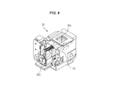
- the fuser driving unit 80 includes a fuser motor 81 which generates a rotary force, a fuser driving gear 82, which is rotated by receiving a rotary force from the fuser motor 81 through gears 84 and 85 to operate the fuser unit 50, and a shaft driving gear 83 which is rotated by receiving a rotary force from the gears 84 and 85 to rotate a shaft 14 that is to be described later.
- waste toner is generated in the developing unit 30.
- a waste toner storage unit including a waste toner storage part 90 and a waste toner delivery part 100 is installed at one side of the body 10.
- the waste toner storage part 90 is detachably installed at one side of the body 10 and stores a waste toner.
- the waste toner delivery part 100 is configured to guide the waste toner separated from the photoconductor 31 to the waste toner storage unit 90.
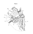
- the waste toner delivery part 100 includes an inlet 100a, an outlet 100b, and a delivery auger 101.
- the inlet 100a is provided at an upper side of the waste toner delivery part 100 to receive waste toner, which falls from the developing unit 30.
- the outlet 100b is provided at a lower side of the waste toner delivery part 100 to deliver the waste toner downward to the waste toner storage part 90.
- the delivery auger 101 delivers the waste toner from the inlet 100a to the outlet 100b.
- gears 102, 103, 104, 105 and 106 are disposed at one side of the waste toner delivery part 100, thereby allowing the delivery auger 101 to rotate through the power transferred from an external source, such as the shaft 14 described in more detail below.
- the waste toner delivery part 100 operates by receiving power from the fuser driving unit 80.
- a shaft 14 is disposed inside the body 10.
- the shaft 14 has a first end connected to the shaft driving gear 83 of the fuser driving unit 80 and a second end connected to a gear of the waste toner delivery part 100 such that the power generated from the fuser driving unit 80 is delivered to the waste toner delivery part 100.
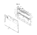
- the waste toner storage part 90 includes a waste toner storage case to accommodate the waste toner and also a flattening auger 93 rotatably installed inside the waste toner storage case to flatten the waste toner stored inside the waste storage toner case.
- the waste toner storage case includes a first case 91 and a second case 92.
- the first case 91 has an open side to accommodate the flattening auger 93 such that the flattening auger 93 is installed inside the first case 91.
- the second case 92 is configured to cover the open side of the first case 91.
- the flattening auger 93 may include two flattening augers 93a and 93b, each laterally extending to move the waste toner in a horizontal direction.
- the two flattening augers 93a and 93b are disposed in parallel with each other.
- gears 94, 95 and 96 are disposed at one side of the waste toner storage case to evenly transfer power to the two flattening augers 93a and 93b.
- the waste toner storage part 90 operates by receiving power from the waste toner delivery part 100. That is, the waste toner storage part 90 operates by receiving some of the power that has been conveyed through the waste toner delivery part 100. To this end, the gears 94, 95 and 96 provided at one side of the waste toner case are engaged with the gears 102, 103, 104, 105 and 106 provided on the waste toner delivery part 100, respectively, to deliver the power from the waste toner delivery part 100 to the waste toner storage part 90.
- the irregular paper delivery unit 70 is provided on the shaft 14 (see FIG. 2 ). That is, since the driving pulley 71 of the irregular paper delivery unit 70 is provided on the shaft 14, the irregular paper delivery unit 70 operates according to the rotation of the shaft 14.
- the fuser driving unit 80 is able to operate the fuser unit 50, the irregular paper delivery unit 70, the waste toner delivery part 100, and the waste toner storage part 90. Accordingly, each of the irregular paper delivery unit 70, the waste toner delivery part 100 and the waste toner storage part 90 is driven through the fuser driving unit 80 without having to install a respective driving unit for each of the irregular paper delivery unit 70, the waste toner delivery part 100, and the waste toner storage part 90.
- the present invention is not limited thereto. According to another example embodiment, the power generated from the fuser driving unit 80 may be transferred to at least one of the irregular paper delivery unit 70, the waste toner delivery part 100, and the waste toner storage part 90.
Landscapes
- Physics & Mathematics (AREA)
- General Physics & Mathematics (AREA)
- Life Sciences & Earth Sciences (AREA)
- Engineering & Computer Science (AREA)
- Environmental & Geological Engineering (AREA)
- Sustainable Development (AREA)
- Cleaning In Electrography (AREA)
- Electrophotography Configuration And Component (AREA)
- Dry Development In Electrophotography (AREA)
- Developing Agents For Electrophotography (AREA)
Applications Claiming Priority (1)
| Application Number | Priority Date | Filing Date | Title |
|---|---|---|---|
| KR1020110000665A KR101622985B1 (ko) | 2011-01-04 | 2011-01-04 | 화상형성장치 |
Publications (3)
| Publication Number | Publication Date |
|---|---|
| EP2472337A2 true EP2472337A2 (de) | 2012-07-04 |
| EP2472337A3 EP2472337A3 (de) | 2017-03-29 |
| EP2472337B1 EP2472337B1 (de) | 2018-11-28 |
Family
ID=45495665
Family Applications (1)
| Application Number | Title | Priority Date | Filing Date |
|---|---|---|---|
| EP11194952.5A Not-in-force EP2472337B1 (de) | 2011-01-04 | 2011-12-21 | Bilderzeugungsvorrichtung |
Country Status (4)
| Country | Link |
|---|---|
| US (1) | US8849174B2 (de) |
| EP (1) | EP2472337B1 (de) |
| KR (1) | KR101622985B1 (de) |
| CN (1) | CN102591164B (de) |
Families Citing this family (5)
| Publication number | Priority date | Publication date | Assignee | Title |
|---|---|---|---|---|
| KR101807008B1 (ko) | 2012-07-20 | 2017-12-08 | 현대자동차 주식회사 | 연속 가변 밸브 리프트 엔진의 제어 방법 |
| JP6443080B2 (ja) * | 2015-01-27 | 2018-12-26 | コニカミノルタ株式会社 | 廃トナー収容装置及び画像形成装置 |
| JP6406174B2 (ja) * | 2015-08-26 | 2018-10-17 | 京セラドキュメントソリューションズ株式会社 | 廃トナー収容容器、画像形成装置 |
| JP6988227B2 (ja) * | 2017-07-25 | 2022-01-05 | 富士フイルムビジネスイノベーション株式会社 | 粉体回収装置および画像形成装置 |
| JP2021170105A (ja) * | 2020-04-15 | 2021-10-28 | キヤノン株式会社 | 現像剤回収装置及び画像形成装置 |
Family Cites Families (14)
| Publication number | Priority date | Publication date | Assignee | Title |
|---|---|---|---|---|
| JP2546851Y2 (ja) * | 1990-01-19 | 1997-09-03 | 株式会社リコー | 電子写真装置の現像装置 |
| JPH07168491A (ja) * | 1993-12-16 | 1995-07-04 | Ricoh Co Ltd | 画像形成装置における廃トナー排出装置 |
| JP3985303B2 (ja) * | 1997-09-04 | 2007-10-03 | コニカミノルタホールディングス株式会社 | 画像形成装置 |
| JP2003345210A (ja) * | 2002-05-24 | 2003-12-03 | Konica Minolta Holdings Inc | 画像形成装置 |
| JP4504712B2 (ja) * | 2004-03-17 | 2010-07-14 | 株式会社リコー | 駆動装置、搬送装置及び画像形成装置 |
| JP4578871B2 (ja) * | 2004-04-01 | 2010-11-10 | 株式会社沖データ | 現像剤回収容器及び画像形成装置 |
| JP4787371B2 (ja) | 2004-04-01 | 2011-10-05 | 株式会社沖データ | 画像形成装置 |
| JP2007010838A (ja) * | 2005-06-29 | 2007-01-18 | Brother Ind Ltd | 画像形成装置 |
| JP2008040222A (ja) * | 2006-08-08 | 2008-02-21 | Fuji Xerox Co Ltd | 現像剤カートリッジ及び画像形成装置 |
| KR101305980B1 (ko) * | 2007-01-26 | 2013-09-12 | 삼성전자주식회사 | 화상형성장치 |
| KR20080072367A (ko) * | 2007-02-02 | 2008-08-06 | 삼성전자주식회사 | 폐토너수집장치 및 이를 갖는 화상형성장치 |
| JP5073463B2 (ja) * | 2007-11-30 | 2012-11-14 | 株式会社リコー | クリーニング装置、像担持体ユニット及び画像形成装置 |
| JP4630912B2 (ja) * | 2008-04-02 | 2011-02-09 | シャープ株式会社 | 画像形成装置 |
| KR20100026638A (ko) * | 2008-09-01 | 2010-03-10 | 삼성전자주식회사 | 화상형성장치 |
-
2011
- 2011-01-04 KR KR1020110000665A patent/KR101622985B1/ko not_active Expired - Fee Related
- 2011-12-21 EP EP11194952.5A patent/EP2472337B1/de not_active Not-in-force
- 2011-12-28 US US13/338,613 patent/US8849174B2/en active Active
-
2012
- 2012-01-04 CN CN201210005451.5A patent/CN102591164B/zh active Active
Non-Patent Citations (1)
| Title |
|---|
| None |
Also Published As
| Publication number | Publication date |
|---|---|
| KR101622985B1 (ko) | 2016-05-20 |
| KR20120079404A (ko) | 2012-07-12 |
| EP2472337A3 (de) | 2017-03-29 |
| CN102591164A (zh) | 2012-07-18 |
| US20120170956A1 (en) | 2012-07-05 |
| US8849174B2 (en) | 2014-09-30 |
| EP2472337B1 (de) | 2018-11-28 |
| CN102591164B (zh) | 2016-06-15 |
Similar Documents
| Publication | Publication Date | Title |
|---|---|---|
| US8532557B2 (en) | Attachment assist device and image forming apparatus including same | |
| CN105607449A (zh) | 盒及使用盒的图像形成装置 | |
| CN101734500B (zh) | 供纸装置以及图像形成装置 | |
| EP2511773B1 (de) | Entwicklerkartusche und Bilderzeugungsvorrichtung, auf die die Entwicklerkartusche angewandt wird | |
| EP2587315A1 (de) | Entwickleraufbewahrungsbehälter und Bilderzeugungsvorrichtung damit | |
| EP2472337B1 (de) | Bilderzeugungsvorrichtung | |
| CN102114994B (zh) | 供纸结构件和装有供纸结构件的图像形成装置 | |
| JP2019182666A (ja) | 画像形成装置 | |
| CN102295170B (zh) | 图像形成装置和送纸装置 | |
| EP2733541A2 (de) | Blattzuführmechanismus, Dokumentenfördervorrichtung und Bilderzeugungsvorrichtung damit | |
| US10845745B2 (en) | Paper feeding device | |
| CN102190176B (zh) | 图像形成装置 | |
| US10067442B2 (en) | Developer storage container with flexible stirring pieces configured so that an extension of one stirring piece is arranged outward of a base of an adjacent stirring piece and image forming apparatus provided with same | |
| EP2738120B1 (de) | Papierzufuhrvorrichtung und Bilderzeugungsvorrichtung damit | |
| KR20170022126A (ko) | 화상형성장치 | |
| JP6411766B2 (ja) | 現像ユニット、画像形成ユニット、及び画像形成装置 | |
| CN102478771A (zh) | 驱动机构和图像形成装置 | |
| JP2008032955A (ja) | ドラムクリーニングユニット及びこれを備えた画像形成装置 | |
| JP2004035132A (ja) | 画像形成装置 | |
| JP3764674B2 (ja) | 給紙装置 | |
| US8923733B2 (en) | Developer supplying device and image forming apparatus | |
| JP2009258514A (ja) | 粉体搬送装置及びこれを搭載した画像形成装置 | |
| US20130154180A1 (en) | Image forming apparatus | |
| JP5845677B2 (ja) | 画像形成装置 | |
| JP2026013064A (ja) | 画像形成装置 |
Legal Events
| Date | Code | Title | Description |
|---|---|---|---|
| AK | Designated contracting states |
Kind code of ref document: A2 Designated state(s): AL AT BE BG CH CY CZ DE DK EE ES FI FR GB GR HR HU IE IS IT LI LT LU LV MC MK MT NL NO PL PT RO RS SE SI SK SM TR |
|
| AX | Request for extension of the european patent |
Extension state: BA ME |
|
| PUAI | Public reference made under article 153(3) epc to a published international application that has entered the european phase |
Free format text: ORIGINAL CODE: 0009012 |
|
| RAP1 | Party data changed (applicant data changed or rights of an application transferred) |
Owner name: SAMSUNG ELECTRONICS CO., LTD. |
|
| PUAL | Search report despatched |
Free format text: ORIGINAL CODE: 0009013 |
|
| RAP1 | Party data changed (applicant data changed or rights of an application transferred) |
Owner name: S-PRINTING SOLUTION CO., LTD. |
|
| AK | Designated contracting states |
Kind code of ref document: A3 Designated state(s): AL AT BE BG CH CY CZ DE DK EE ES FI FR GB GR HR HU IE IS IT LI LT LU LV MC MK MT NL NO PL PT RO RS SE SI SK SM TR |
|
| AX | Request for extension of the european patent |
Extension state: BA ME |
|
| RIC1 | Information provided on ipc code assigned before grant |
Ipc: G03G 15/20 20060101ALI20170218BHEP Ipc: G03G 15/00 20060101ALI20170218BHEP Ipc: G03G 21/12 20060101ALI20170218BHEP Ipc: G03G 21/10 20060101AFI20170218BHEP |
|
| 17P | Request for examination filed |
Effective date: 20170623 |
|
| RBV | Designated contracting states (corrected) |
Designated state(s): AL AT BE BG CH CY CZ DE DK EE ES FI FR GB GR HR HU IE IS IT LI LT LU LV MC MK MT NL NO PL PT RO RS SE SI SK SM TR |
|
| RAP1 | Party data changed (applicant data changed or rights of an application transferred) |
Owner name: HP PRINTING KOREA CO., LTD. |
|
| GRAP | Despatch of communication of intention to grant a patent |
Free format text: ORIGINAL CODE: EPIDOSNIGR1 |
|
| INTG | Intention to grant announced |
Effective date: 20180808 |
|
| GRAS | Grant fee paid |
Free format text: ORIGINAL CODE: EPIDOSNIGR3 |
|
| GRAA | (expected) grant |
Free format text: ORIGINAL CODE: 0009210 |
|
| AK | Designated contracting states |
Kind code of ref document: B1 Designated state(s): AL AT BE BG CH CY CZ DE DK EE ES FI FR GB GR HR HU IE IS IT LI LT LU LV MC MK MT NL NO PL PT RO RS SE SI SK SM TR |
|
| REG | Reference to a national code |
Ref country code: GB Ref legal event code: FG4D |
|
| REG | Reference to a national code |
Ref country code: CH Ref legal event code: EP |
|
| REG | Reference to a national code |
Ref country code: AT Ref legal event code: REF Ref document number: 1070948 Country of ref document: AT Kind code of ref document: T Effective date: 20181215 |
|
| REG | Reference to a national code |
Ref country code: DE Ref legal event code: R096 Ref document number: 602011054262 Country of ref document: DE |
|
| REG | Reference to a national code |
Ref country code: IE Ref legal event code: FG4D |
|
| REG | Reference to a national code |
Ref country code: NL Ref legal event code: MP Effective date: 20181128 |
|
| REG | Reference to a national code |
Ref country code: LT Ref legal event code: MG4D |
|
| REG | Reference to a national code |
Ref country code: AT Ref legal event code: MK05 Ref document number: 1070948 Country of ref document: AT Kind code of ref document: T Effective date: 20181128 |
|
| PG25 | Lapsed in a contracting state [announced via postgrant information from national office to epo] |
Ref country code: ES Free format text: LAPSE BECAUSE OF FAILURE TO SUBMIT A TRANSLATION OF THE DESCRIPTION OR TO PAY THE FEE WITHIN THE PRESCRIBED TIME-LIMIT Effective date: 20181128 Ref country code: AT Free format text: LAPSE BECAUSE OF FAILURE TO SUBMIT A TRANSLATION OF THE DESCRIPTION OR TO PAY THE FEE WITHIN THE PRESCRIBED TIME-LIMIT Effective date: 20181128 Ref country code: LV Free format text: LAPSE BECAUSE OF FAILURE TO SUBMIT A TRANSLATION OF THE DESCRIPTION OR TO PAY THE FEE WITHIN THE PRESCRIBED TIME-LIMIT Effective date: 20181128 Ref country code: LT Free format text: LAPSE BECAUSE OF FAILURE TO SUBMIT A TRANSLATION OF THE DESCRIPTION OR TO PAY THE FEE WITHIN THE PRESCRIBED TIME-LIMIT Effective date: 20181128 Ref country code: HR Free format text: LAPSE BECAUSE OF FAILURE TO SUBMIT A TRANSLATION OF THE DESCRIPTION OR TO PAY THE FEE WITHIN THE PRESCRIBED TIME-LIMIT Effective date: 20181128 Ref country code: BG Free format text: LAPSE BECAUSE OF FAILURE TO SUBMIT A TRANSLATION OF THE DESCRIPTION OR TO PAY THE FEE WITHIN THE PRESCRIBED TIME-LIMIT Effective date: 20190228 Ref country code: IS Free format text: LAPSE BECAUSE OF FAILURE TO SUBMIT A TRANSLATION OF THE DESCRIPTION OR TO PAY THE FEE WITHIN THE PRESCRIBED TIME-LIMIT Effective date: 20190328 Ref country code: FI Free format text: LAPSE BECAUSE OF FAILURE TO SUBMIT A TRANSLATION OF THE DESCRIPTION OR TO PAY THE FEE WITHIN THE PRESCRIBED TIME-LIMIT Effective date: 20181128 Ref country code: NO Free format text: LAPSE BECAUSE OF FAILURE TO SUBMIT A TRANSLATION OF THE DESCRIPTION OR TO PAY THE FEE WITHIN THE PRESCRIBED TIME-LIMIT Effective date: 20190228 |
|
| PG25 | Lapsed in a contracting state [announced via postgrant information from national office to epo] |
Ref country code: SE Free format text: LAPSE BECAUSE OF FAILURE TO SUBMIT A TRANSLATION OF THE DESCRIPTION OR TO PAY THE FEE WITHIN THE PRESCRIBED TIME-LIMIT Effective date: 20181128 Ref country code: GR Free format text: LAPSE BECAUSE OF FAILURE TO SUBMIT A TRANSLATION OF THE DESCRIPTION OR TO PAY THE FEE WITHIN THE PRESCRIBED TIME-LIMIT Effective date: 20190301 Ref country code: RS Free format text: LAPSE BECAUSE OF FAILURE TO SUBMIT A TRANSLATION OF THE DESCRIPTION OR TO PAY THE FEE WITHIN THE PRESCRIBED TIME-LIMIT Effective date: 20181128 Ref country code: PT Free format text: LAPSE BECAUSE OF FAILURE TO SUBMIT A TRANSLATION OF THE DESCRIPTION OR TO PAY THE FEE WITHIN THE PRESCRIBED TIME-LIMIT Effective date: 20190328 Ref country code: AL Free format text: LAPSE BECAUSE OF FAILURE TO SUBMIT A TRANSLATION OF THE DESCRIPTION OR TO PAY THE FEE WITHIN THE PRESCRIBED TIME-LIMIT Effective date: 20181128 |
|
| PG25 | Lapsed in a contracting state [announced via postgrant information from national office to epo] |
Ref country code: NL Free format text: LAPSE BECAUSE OF FAILURE TO SUBMIT A TRANSLATION OF THE DESCRIPTION OR TO PAY THE FEE WITHIN THE PRESCRIBED TIME-LIMIT Effective date: 20181128 |
|
| PG25 | Lapsed in a contracting state [announced via postgrant information from national office to epo] |
Ref country code: DK Free format text: LAPSE BECAUSE OF FAILURE TO SUBMIT A TRANSLATION OF THE DESCRIPTION OR TO PAY THE FEE WITHIN THE PRESCRIBED TIME-LIMIT Effective date: 20181128 Ref country code: IT Free format text: LAPSE BECAUSE OF FAILURE TO SUBMIT A TRANSLATION OF THE DESCRIPTION OR TO PAY THE FEE WITHIN THE PRESCRIBED TIME-LIMIT Effective date: 20181128 Ref country code: CZ Free format text: LAPSE BECAUSE OF FAILURE TO SUBMIT A TRANSLATION OF THE DESCRIPTION OR TO PAY THE FEE WITHIN THE PRESCRIBED TIME-LIMIT Effective date: 20181128 Ref country code: PL Free format text: LAPSE BECAUSE OF FAILURE TO SUBMIT A TRANSLATION OF THE DESCRIPTION OR TO PAY THE FEE WITHIN THE PRESCRIBED TIME-LIMIT Effective date: 20181128 |
|
| REG | Reference to a national code |
Ref country code: CH Ref legal event code: PL |
|
| REG | Reference to a national code |
Ref country code: DE Ref legal event code: R097 Ref document number: 602011054262 Country of ref document: DE |
|
| PG25 | Lapsed in a contracting state [announced via postgrant information from national office to epo] |
Ref country code: SK Free format text: LAPSE BECAUSE OF FAILURE TO SUBMIT A TRANSLATION OF THE DESCRIPTION OR TO PAY THE FEE WITHIN THE PRESCRIBED TIME-LIMIT Effective date: 20181128 Ref country code: RO Free format text: LAPSE BECAUSE OF FAILURE TO SUBMIT A TRANSLATION OF THE DESCRIPTION OR TO PAY THE FEE WITHIN THE PRESCRIBED TIME-LIMIT Effective date: 20181128 Ref country code: LU Free format text: LAPSE BECAUSE OF NON-PAYMENT OF DUE FEES Effective date: 20181221 Ref country code: MC Free format text: LAPSE BECAUSE OF FAILURE TO SUBMIT A TRANSLATION OF THE DESCRIPTION OR TO PAY THE FEE WITHIN THE PRESCRIBED TIME-LIMIT Effective date: 20181128 Ref country code: SM Free format text: LAPSE BECAUSE OF FAILURE TO SUBMIT A TRANSLATION OF THE DESCRIPTION OR TO PAY THE FEE WITHIN THE PRESCRIBED TIME-LIMIT Effective date: 20181128 Ref country code: EE Free format text: LAPSE BECAUSE OF FAILURE TO SUBMIT A TRANSLATION OF THE DESCRIPTION OR TO PAY THE FEE WITHIN THE PRESCRIBED TIME-LIMIT Effective date: 20181128 |
|
| REG | Reference to a national code |
Ref country code: IE Ref legal event code: MM4A |
|
| REG | Reference to a national code |
Ref country code: BE Ref legal event code: MM Effective date: 20181231 |
|
| PLBE | No opposition filed within time limit |
Free format text: ORIGINAL CODE: 0009261 |
|
| STAA | Information on the status of an ep patent application or granted ep patent |
Free format text: STATUS: NO OPPOSITION FILED WITHIN TIME LIMIT |
|
| PG25 | Lapsed in a contracting state [announced via postgrant information from national office to epo] |
Ref country code: SI Free format text: LAPSE BECAUSE OF FAILURE TO SUBMIT A TRANSLATION OF THE DESCRIPTION OR TO PAY THE FEE WITHIN THE PRESCRIBED TIME-LIMIT Effective date: 20181128 Ref country code: IE Free format text: LAPSE BECAUSE OF NON-PAYMENT OF DUE FEES Effective date: 20181221 |
|
| 26N | No opposition filed |
Effective date: 20190829 |
|
| PG25 | Lapsed in a contracting state [announced via postgrant information from national office to epo] |
Ref country code: BE Free format text: LAPSE BECAUSE OF NON-PAYMENT OF DUE FEES Effective date: 20181231 |
|
| REG | Reference to a national code |
Ref country code: DE Ref legal event code: R082 Ref document number: 602011054262 Country of ref document: DE Representative=s name: SCHOPPE, ZIMMERMANN, STOECKELER, ZINKLER, SCHE, DE Ref country code: DE Ref legal event code: R081 Ref document number: 602011054262 Country of ref document: DE Owner name: HEWLETT-PACKARD DEVELOPMENT COMPANY, L.P., SPR, US Free format text: FORMER OWNER: HP PRINTING KOREA CO., LTD., SUWON-SI, GYEONGGI-DO, KR |
|
| PG25 | Lapsed in a contracting state [announced via postgrant information from national office to epo] |
Ref country code: CH Free format text: LAPSE BECAUSE OF NON-PAYMENT OF DUE FEES Effective date: 20181231 Ref country code: LI Free format text: LAPSE BECAUSE OF NON-PAYMENT OF DUE FEES Effective date: 20181231 |
|
| PG25 | Lapsed in a contracting state [announced via postgrant information from national office to epo] |
Ref country code: MT Free format text: LAPSE BECAUSE OF NON-PAYMENT OF DUE FEES Effective date: 20181221 |
|
| PG25 | Lapsed in a contracting state [announced via postgrant information from national office to epo] |
Ref country code: TR Free format text: LAPSE BECAUSE OF FAILURE TO SUBMIT A TRANSLATION OF THE DESCRIPTION OR TO PAY THE FEE WITHIN THE PRESCRIBED TIME-LIMIT Effective date: 20181128 |
|
| PG25 | Lapsed in a contracting state [announced via postgrant information from national office to epo] |
Ref country code: HU Free format text: LAPSE BECAUSE OF FAILURE TO SUBMIT A TRANSLATION OF THE DESCRIPTION OR TO PAY THE FEE WITHIN THE PRESCRIBED TIME-LIMIT; INVALID AB INITIO Effective date: 20111221 Ref country code: CY Free format text: LAPSE BECAUSE OF FAILURE TO SUBMIT A TRANSLATION OF THE DESCRIPTION OR TO PAY THE FEE WITHIN THE PRESCRIBED TIME-LIMIT Effective date: 20181128 Ref country code: MK Free format text: LAPSE BECAUSE OF NON-PAYMENT OF DUE FEES Effective date: 20181128 |
|
| REG | Reference to a national code |
Ref country code: GB Ref legal event code: 732E Free format text: REGISTERED BETWEEN 20200917 AND 20200923 |
|
| PGFP | Annual fee paid to national office [announced via postgrant information from national office to epo] |
Ref country code: FR Payment date: 20211117 Year of fee payment: 11 Ref country code: GB Payment date: 20211118 Year of fee payment: 11 |
|
| PGFP | Annual fee paid to national office [announced via postgrant information from national office to epo] |
Ref country code: DE Payment date: 20221122 Year of fee payment: 12 |
|
| GBPC | Gb: european patent ceased through non-payment of renewal fee |
Effective date: 20221221 |
|
| PG25 | Lapsed in a contracting state [announced via postgrant information from national office to epo] |
Ref country code: GB Free format text: LAPSE BECAUSE OF NON-PAYMENT OF DUE FEES Effective date: 20221221 |
|
| PG25 | Lapsed in a contracting state [announced via postgrant information from national office to epo] |
Ref country code: FR Free format text: LAPSE BECAUSE OF NON-PAYMENT OF DUE FEES Effective date: 20221231 |
|
| REG | Reference to a national code |
Ref country code: DE Ref legal event code: R119 Ref document number: 602011054262 Country of ref document: DE |
|
| PG25 | Lapsed in a contracting state [announced via postgrant information from national office to epo] |
Ref country code: DE Free format text: LAPSE BECAUSE OF NON-PAYMENT OF DUE FEES Effective date: 20240702 |
|
| PG25 | Lapsed in a contracting state [announced via postgrant information from national office to epo] |
Ref country code: DE Free format text: LAPSE BECAUSE OF NON-PAYMENT OF DUE FEES Effective date: 20240702 |