EP2471698B1 - Vehicle body rear structure - Google Patents
Vehicle body rear structure Download PDFInfo
- Publication number
- EP2471698B1 EP2471698B1 EP10823250.5A EP10823250A EP2471698B1 EP 2471698 B1 EP2471698 B1 EP 2471698B1 EP 10823250 A EP10823250 A EP 10823250A EP 2471698 B1 EP2471698 B1 EP 2471698B1
- Authority
- EP
- European Patent Office
- Prior art keywords
- wheelhouse
- stiffener
- inner panel
- seat
- vehicle body
- Prior art date
- Legal status (The legal status is an assumption and is not a legal conclusion. Google has not performed a legal analysis and makes no representation as to the accuracy of the status listed.)
- Not-in-force
Links
Images


Classifications
-
- B—PERFORMING OPERATIONS; TRANSPORTING
- B62—LAND VEHICLES FOR TRAVELLING OTHERWISE THAN ON RAILS
- B62D—MOTOR VEHICLES; TRAILERS
- B62D25/00—Superstructure or monocoque structure sub-units; Parts or details thereof not otherwise provided for
- B62D25/08—Front or rear portions
- B62D25/087—Luggage compartments
-
- B—PERFORMING OPERATIONS; TRANSPORTING
- B60—VEHICLES IN GENERAL
- B60N—SEATS SPECIALLY ADAPTED FOR VEHICLES; VEHICLE PASSENGER ACCOMMODATION NOT OTHERWISE PROVIDED FOR
- B60N2/00—Seats specially adapted for vehicles; Arrangement or mounting of seats in vehicles
- B60N2/24—Seats specially adapted for vehicles; Arrangement or mounting of seats in vehicles for particular purposes or particular vehicles
- B60N2/32—Seats specially adapted for vehicles; Arrangement or mounting of seats in vehicles for particular purposes or particular vehicles convertible for other use
- B60N2/36—Seats specially adapted for vehicles; Arrangement or mounting of seats in vehicles for particular purposes or particular vehicles convertible for other use into a loading platform
- B60N2/366—Seats specially adapted for vehicles; Arrangement or mounting of seats in vehicles for particular purposes or particular vehicles convertible for other use into a loading platform characterised by the locking device
Definitions
- the present invention relates to an improvement in a vehicle body rear structure of a vehicle provided with a folding seat back.
- Patent Literature 1 There has been known a vehicle body rear structure wherein a folding seat back of a rear seat is engaged with a suspension tower of a vehicle body, as disclosed in Patent Literature 1.
- a latch plate is provided on a rear seat back, a suspension tower is provided on a rear wheelhouse inner at the vehicle body side, and a striker is attached to an upper end portion of the suspension tower via an attaching plate, wherein the latch plate is adapted to engage with the striker.
- JP 2006193047 A discloses a vehicle body rear structure, comprising: a seat including a folding seat back; a rear wheelhouse inner panel forming a part of a vehicle body and curved to protrude toward an inner side of the vehicle body in a vehicle width direction, wherein the rear wheelhouse inner panel is joined by welding to a vehicle body side wall part arranged above the rear wheelhouse inner panel; and a seat striker provided for undertaking engaging and disengaging between an engaging part provided on a rear face of the seat back and the vehicle body side wall part.
- a stiffener attached to a vehicle-interior-side surface of the vehicle body side wall part and the vehicle body side wall part form a dogleg-shaped closed section
- the seat striker is attached to a bracket provided on the vehicle-interior-side surface of the stiffener.
- EP 1769966 A2 discloses a vehicle body rear structure, comprising, a seat including a folding seat back; a rear wheelhouse inner panel forming a part of a vehicle body and curved to protrude toward an inner side of the vehicle body in a vehicle width direction, wherein the rear wheelhouse inner panel includes a wheelhouse base forming a lower half part of the rear wheelhouse inner panel and a wheelhouse extension extending integrally upward from an upper end of the wheelhouse base and forming a planar vehicle sidewall portion.
- a seat striker is attached to a planar attaching plate directly provided on the planar vehicle sidewall portion.
- the seat striker In a case where the engagement position between the latch plate and the striker is close to the suspension tower as in JPH11115597 A, it is possible to attach the striker to the highly rigid suspension tower so as to support or bear a load acting on the rear seat back.
- the seat striker requires, for its attachment to the suspension tower, a large-sized stiffener extending from the suspension tower to the seat striker.
- the seat striker may be further required to be attached to the stiffener via a patch depending on a shape of the stiffener. Consequently, the weight of components (the stiffener, the patch and the like) to ensure stiffness for supporting the striker is increased and the number of parts or parts count increases as well.
- An object of the present invention is to provide a vehicle body rear structure which ensures seat striker supporting stiffness and improves a reinforcement of the rear wheelhouse inner panel even when the position of a seat striker position is apart from a damper attaching portion which supports a suspension.
- the vehicle body rear structure comprises: a seat including a folding seat back; a rear wheelhouse inner panel forming a part of a vehicle body and curved to protrude toward an inner side of the vehicle body in a vehicle width direction; and a seat striker provided for undertaking engaging and disengaging between an engaging part provided on a rear face of the seat back and the rear wheelhouse inner panel, wherein the rear wheelhouse inner panel includes a wheelhouse base forming a lower half part of the rear wheelhouse inner panel and a wheelhouse extension extending integrally upward from an upper end of the wheelhouse base, a stiffener attached to a vehicle-interior-side surface of the wheelhouse extension and the rear wheelhouse inner panel form a dogleg-shaped closed cross-section, and the seat striker is attached to a bracket provided on at a vehicle-interior-side surface of the stiffener.
- the stiffener is joined to the wheelhouse extension by welding
- the bracket is joined to the stiffener by welding
- the number of welded portions between the wheelhouse extension and the stiffener is larger than the number of welded portions between the stiffener and the bracket.
- the wheelhouse extension has a flange at an upper end thereof, and the upper end flange is joined to a roof rail.
- the stiffener and a damper attaching portion provided on the rear wheelhouse inner panel are joined continuously along a curved surface of the rear wheelhouse inner panel.
- the damper attaching portion has an upper surface, and the upper surface of the damper attaching portion is connected to a roof rail via a reinforcement member.
- the wheelhouse extension of which cross-section is formed as being curved obtains high stiffness in the vehicle width direction. Further, since the dogleg-shaped closed cross-section is formed with the stiffener, it is possible to ensure stiffness of the seat striker attaching portion which is constituted by the wheelhouse extension, the stiffener, and the bracket.
- the seat striker attaching portion it is possible to use a small-sized stiffener for reinforcing the seat striker attaching portion, so that reduction in weight and parts count can be achieved.
- the number of welded portions of each component in the seat striker attaching portion becomes large as approaching from the seat striker to the rear wheelhouse inner panel, so that the load acting on the seat striker is more likely to be distributed to the rear wheelhouse inner panel. That is, the load acting on the seat can be more likely to be distributed as being transmitted in the order of the striker, the bracket, the stiffener, and the rear wheelhouse inner panel.
- stiffness of the rear wheelhouse inner panel is increased and the load transmitted from the seat side to the rear wheelhouse inner panel via the seat striker is transmitted from the rear wheelhouse inner panel to the roof rail. That is, the seat load acting on the seat is distributed from the rear wheelhouse inner panel to the roof rail.
- the stiffener and the damper attaching portion provided on the rear wheelhouse inner panel are joined continuously along the curved surface of the rear wheelhouse inner panel, the rear wheel house inner panel is continuously reinforced by the stiffener and the damper attaching portion.
- the damper attaching portion Since the upper surface of the damper attaching portion is connected to the roof rail via the reinforcement member, the damper attaching portion is reinforced by the reinforcement member itself and connection with the roof rail. That is, the damper attaching portion is reinforced, so that damper supporting stiffness can be increased. Further, the seat striker attaching portion is reinforced owing to connection between the damper attaching portion and the stiffener, so that the seat can be supported further strongly.
- a rear wheelhouse inner panel 13 is provided at each rear part of a left side body 11 and a right side body 12 that constitute a vehicle body (here, only one numeral 13 is indicated).
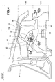
- a rear seat 14 includes a folding seat back 16 and a seat cushion 18. The seat back 16 is swingably attached to a rear end part of the seat cushion 18. The seat back 16 is releasably engaged with each rear wheelhouse inner panel 13 via an engaging device 17.
- Lest and right roof side rails 22 are extended rearward respectively from upper end parts of left and right center pillars 21 (here, only one side is illustrated).
- the left and right center pillars 23 are extended downward respectively from longitudinal intermediate portions of the left and right roof side rails 22. Lower end parts of the center pillars 23 are supported respectively by left and right side sills: 24 (here, only one side is illustrated).
- a middle floor-cross member 26 connects the left and right side sills 24.
- a rear panel 27 is disposed behind the seat back 16.
- the rear wheel house inner panel 13 includes a wheelhouse base 13A which constitutes a lower half part and a wheelhouse extending part or extension 13B which extends integrally upward from the wheelhouse base 13A.
- a lower end part of the wheelhouse base 13A is attached to a rear floor panel 33 and a rear frame (not illustrated).
- a front end part and a rear end part of each of the wheelhouse base 13A and the wheelhouse extension 13B are attached to a rear wheelhouse outer panel 34.
- An upper end part of the wheelhouse extension 13B is attached to the roof side rail 22.
- the wheelhouse base 13A and the wheelhouse extension 13B are curved to protrude toward an inner side of the vehicle body in the vehicle width direction.
- a panel-shaped stiffener 36 is attached by welding to the wheelhouse base 13A and the wheelhouse extension 13B respectively from a front face to a side face.
- a plate-shaped bracket 37 is attached to the stiffener 36 by welding. Further, a seat striker 38 is fastened to the bracket 37.
- a seat striker attaching portion 40 is formed with the wheelhouse base 13A, the wheelhouse extension 13B, the stiffener 36 and the bracket 37.
- the seat striker 38 is a component constituting the engaging device 17 with an engaging part 16a (in Fig. 6(a) ) which is provided on a rear face of the seat back 16 illustrated in Fig. 1 .
- the seat striker 38 includes a base plate 41 attached to the bracket 37 and a striker main body 42 attached to the base plate 41.
- damper attaching portion 45 which is formed of a panel.
- the damper attaching portion 45 is attached to a rear part of the rear wheelhouse inner panel 13 as being continued to a rear end of the stiffener 36.
- a damper attaching portion stiffener 46 to reinforce the damper attaching portion 45 is attached to the rear wheelhouse inner panel 13 and an upper face of the damper attaching portion 45.
- the rear wheelhouse inner panel 13 is a trapezoid-like member including the wheelhouse base 13A to which the damper attaching portion 45 is attached and the wheelhouse extension 13B which extends upward from the wheelhouse base 13A.
- a lower side of the trapezoid-like rear wheelhouse inner panel 13 is attached to the rear floor panel 33 ( Fig. 2 ) and a rear frame 53 ( Fig. 5 ).
- An upper side of the rear wheelhouse inner panel 13 is attached to the roof side rail 22.
- damper attaching portion 45 can be further reinforced.
- Fig. 5 is a view of a center inside panel 51 and the rear wheelhouse inner panel 13 as viewed from the outside of a vehicle room excluding a rear outside panel (not illustrated) of the right side body 12 and the rear wheelhouse outer panel 34 ( Fig. 2 ).
- the rear frame 53 extends in the vehicle body front-back direction.
- the lower end part of the rear wheelhouse inner panel 13 is attached to the rear frame 53.
- the lower end part of the center inside panel 51 is attached to the rear frame 53 and the upper end part thereof is attached to the roof side rail 22.
- Fig. 6(a) illustrates a cross-section along line 6a-6a of Fig. 4 .
- the rear wheelhouse inner panel 13 curved to protrude toward the inside of the vehicle room is joined with the stiffener 36 curved to similarly protrude toward the inside of the vehicle room, so that a first space 55 defined by a dogleg-shaped closed cross-section is formed between the rear wheelhouse inner panel 13 and the stiffener 36.
- stiffener 36 is joined with the bracket 37 curved to protrude toward the inside of the vehicle room, so that a second space 56 defined by a closed cross-section is formed between the stiffener 36 and the bracket 37.
- stiffness of the seat striker attaching portion 40 can be further increased.
- the striker main body 42 of the seat striker 38 extends obliquely and laterally frontward from the bracket 37, and the engaging part 16a of the seat back 16 ( Fig. 1 ) is engaged with a top end part of the striker main body 42. Accordingly, a load in the front-rear direction acting on the seat back 16, especially a rearward seat load, acts on the striker main body 42 via the engaging part 16a.
- the two closed cross-sections i.e., the first space 55 and the second space 56
- the rearward seat load is more likely to be supported by the entire seat striker attaching portion 40. Accordingly, load supporting can be effectively performed. Therefore, required stiffness can be ensured even if thickness of the stiffener 36 and the bracket 37 is lessened, so that reduction in weight can be achieved.
- Fig. 6(b) illustrates a cross-section along line 6b-6b of Fig. 4 .
- the stiffener 36 and the damper attaching portion 45 are continuously attached to the rear wheelhouse inner panel 13.
- the reinforcement effect of the rear wheelhouse inner panel 13 is further enhanced.
- Fig. 7A illustrates a vehicle-interior-side surface of the rear wheelhouse inner panel 13.
- the rear wheelhouse inner panel 13 is curved to protrude toward the vehicle room side.
- Fig. 7B illustrates a state where the stiffener 36, more specifically, a flange 36a formed at an edge of the stiffener 36, is attached to the rear wheelhouse inner panel 13 by welding.
- the stiffener 36 has a protruded wall 36b formed integrally with a portion thereof surrounded by the flange 36a and projecting in a stepped manner from the flange 36a to the vehicle room side.
- the dogleg-shaped closed cross-section is formed between the rear wheelhouse inner panel 13 and the protruded wall 36b.
- x-marks at the flange 36a indicate welded portions of the flange 36a relative to the rear wheelhouse inner panel 13 by spot welding.
- the number of the welded portions is seventeen.
- Fig. 7C illustrates a state where the bracket 37, more specifically, an edge portion 37a of the bracket 37, is attached to the stiffener 36 by welding.
- a protruded flat wall 37b which is flat as being protruded to the vehicle room side from the edge portion 37a is formed at a part of the bracket 37 surrounded by the edge portion 37a.
- the closed cross-section is formed between the stiffener 36 and the bracket 37. Accordingly, the seat striker 38 can be attached to the protruded flat wall 37b with bolts and nuts.
- Bolt-insertion holes 37c, 37c are formed at the protruded flat portion 37b through which bolts for fastening the seat striker 38 pass.
- ⁇ -marks at the edge portion 37a of the bracket 37 indicate welded portions of the edge portion 37a relative to the stiffener 36 by spot welding.
- the number of the welding positions is eight.
- Fig. 7D illustrates a state where the seat striker 38 is fastened to the protruded flat portion 37b (Fig. 8C) of the bracket 37 with two bolts 61, 61 and nuts (not illustrated) attached to a back face of the protruded flat wall 37b. Thus, attaching of the seat striker 38 is completed.
- the vehicle body rear structure of the present invention is provided with the seat striker 38 at the vehicle body side to be engaged with the engaging part 16a of the folding seat back 16 which constitutes the rear seat 14.
- the wheelhouse extension 13B as a swelling portion is formed at the rear wheelhouse inner panel 13 as being extended upward in a state where the cross-section is curved to protrude toward the vehicle room side.
- the dogleg-shaped closed cross-section is formed with the stiffener 36 and the rear wheelhouse inner panel 13 by attaching the stiffener 36 to the vehicle-interior-side surface of the wheelhouse extension 13B.
- the seat striker 38 is attached to the vehicle-interior-side surface of the stiffener 36 via the bracket 37.
- the dogleg-shaped closed cross-section is formed with the wheelhouse extension 13B and the stiffener 36 having a curved cross-section, stiffness of the seat striker attaching portion 40 can be ensured.
- the small-sized stiffener 36 can be used for reinforcing the seat striker attaching portion 40, so that reduction in weight and parts count can be achieved.
- the stiffener 36 is joined to the wheelhouse extension 13B by welding and the bracket 37 is joined to the stiffener 36 by welding. Since the number of welded portions between the wheelhouse extension 13B and the stiffener 36 is larger than the number of welded portions between the stiffener 36 and the bracket 37, the load acting on the rear seat 14 ( Fig. 1 ) can be more likely to be distributed as being transmitted in the order of the seat striker 38, the bracket 37, the stiffener 36 and the rear wheelhouse inner panel 13.
- an upper end flange 13a is formed at the wheelhouse extension 13B and the upper end flange 13a is joined to the roof side rail 22 being the roof rail. Accordingly, stiffness of the rear wheelhouse inner panel 13 can be increased and the seat load acting on the rear seat 14 can be distributed from the rear wheelhouse inner panel 13 to the roof side rail 22.
- the stiffener 36 and the damper attaching portion 45 provided on the rear wheelhouse inner panel 13 are joined as being continued along the curved surface of the rear wheelhouse inner panel 13. Accordingly, the rear wheelhouse inner panel 13 can be reinforced continuously with the stiffener 36 and the damper attaching portion 45.
- the upper surface of the damper attaching portion 45 is connected to the roof side rail 22 with the damper attaching portion stiffener 46 being a reinforcement member. Accordingly, damper supporting stiffness can be increased as the damper attaching portion 45 being reinforced. Further, since the damper attaching portion 45 is also joined to the stiffener 36, the seat striker attaching portion 40 is reinforced as well. Therefore, the rear seat 14 ( Fig. 1 ) can be supported further strongly.
- the vehicle body rear structure of the present invention is suitable for automobiles.
Landscapes
- Engineering & Computer Science (AREA)
- Transportation (AREA)
- Mechanical Engineering (AREA)
- Chemical & Material Sciences (AREA)
- Combustion & Propulsion (AREA)
- Aviation & Aerospace Engineering (AREA)
- Body Structure For Vehicles (AREA)
Applications Claiming Priority (2)
| Application Number | Priority Date | Filing Date | Title |
|---|---|---|---|
| JP2009236176 | 2009-10-13 | ||
| PCT/JP2010/064593 WO2011045982A1 (ja) | 2009-10-13 | 2010-08-27 | 車体後部構造 |
Publications (3)
| Publication Number | Publication Date |
|---|---|
| EP2471698A1 EP2471698A1 (en) | 2012-07-04 |
| EP2471698A4 EP2471698A4 (en) | 2013-03-13 |
| EP2471698B1 true EP2471698B1 (en) | 2014-05-07 |
Family
ID=43876037
Family Applications (1)
| Application Number | Title | Priority Date | Filing Date |
|---|---|---|---|
| EP10823250.5A Not-in-force EP2471698B1 (en) | 2009-10-13 | 2010-08-27 | Vehicle body rear structure |
Country Status (5)
| Country | Link |
|---|---|
| US (1) | US8517460B2 (zh) |
| EP (1) | EP2471698B1 (zh) |
| JP (1) | JP5369190B2 (zh) |
| CN (1) | CN102574550B (zh) |
| WO (1) | WO2011045982A1 (zh) |
Families Citing this family (9)
| Publication number | Priority date | Publication date | Assignee | Title |
|---|---|---|---|---|
| KR101439145B1 (ko) * | 2013-03-19 | 2014-09-11 | 현대자동차주식회사 | 차량의 리어 패키지트레이 구조 |
| JP5639691B1 (ja) * | 2013-07-08 | 2014-12-10 | 株式会社ホンダアクセス | 板状部材に対する部品の取付構造 |
| JP5666656B2 (ja) * | 2013-07-08 | 2015-02-12 | 株式会社ホンダアクセス | 板状部材に対する部品の取付構造 |
| CN105722747B (zh) * | 2013-11-15 | 2017-11-14 | 本田技研工业株式会社 | 车身侧部构造 |
| CN105764779B (zh) * | 2013-11-19 | 2018-09-07 | 本田技研工业株式会社 | 车身后部构造 |
| JP6350227B2 (ja) * | 2014-11-07 | 2018-07-04 | スズキ株式会社 | シートバック保持部材の取付構造 |
| US9403492B1 (en) * | 2015-03-27 | 2016-08-02 | Nissan North America, Inc. | Vehicle body structure |
| KR102417345B1 (ko) * | 2017-07-27 | 2022-07-05 | 현대자동차 주식회사 | 차량용 리어 시트백 스트라이커 마운팅 구조 |
| CN113276730A (zh) * | 2021-06-30 | 2021-08-20 | 一汽奔腾轿车有限公司 | 一种乘用车后排座椅转轴固定结构 |
Family Cites Families (8)
| Publication number | Priority date | Publication date | Assignee | Title |
|---|---|---|---|---|
| JP2516212B2 (ja) * | 1987-04-17 | 1996-07-24 | マツダ株式会社 | 自動車の前部車体構造 |
| JPH0550947A (ja) * | 1991-08-23 | 1993-03-02 | Toyota Motor Corp | 補強ピラーの取付構造 |
| JP3307849B2 (ja) * | 1997-02-10 | 2002-07-24 | ダイハツ工業株式会社 | 自動車の車体後側部構造 |
| JP3885316B2 (ja) | 1997-10-15 | 2007-02-21 | 日産自動車株式会社 | リヤシートバック固定用ブラケット配設構造 |
| JP4314991B2 (ja) | 2003-12-11 | 2009-08-19 | マツダ株式会社 | 車体後部構造 |
| JP4556674B2 (ja) | 2005-01-13 | 2010-10-06 | マツダ株式会社 | 車両の側部車体構造 |
| JP2007098976A (ja) * | 2005-09-30 | 2007-04-19 | Mazda Motor Corp | シートを備えた車両の車体構造 |
| JP2008062748A (ja) * | 2006-09-06 | 2008-03-21 | Mazda Motor Corp | 車両の側部車体構造 |
-
2010
- 2010-08-27 EP EP10823250.5A patent/EP2471698B1/en not_active Not-in-force
- 2010-08-27 JP JP2011536075A patent/JP5369190B2/ja not_active Expired - Fee Related
- 2010-08-27 US US13/500,426 patent/US8517460B2/en active Active
- 2010-08-27 WO PCT/JP2010/064593 patent/WO2011045982A1/ja active Application Filing
- 2010-08-27 CN CN201080044364.XA patent/CN102574550B/zh not_active Expired - Fee Related
Also Published As
| Publication number | Publication date |
|---|---|
| US8517460B2 (en) | 2013-08-27 |
| JPWO2011045982A1 (ja) | 2013-03-04 |
| JP5369190B2 (ja) | 2013-12-18 |
| CN102574550B (zh) | 2014-09-10 |
| WO2011045982A1 (ja) | 2011-04-21 |
| US20120200109A1 (en) | 2012-08-09 |
| EP2471698A4 (en) | 2013-03-13 |
| EP2471698A1 (en) | 2012-07-04 |
| CN102574550A (zh) | 2012-07-11 |
Similar Documents
| Publication | Publication Date | Title |
|---|---|---|
| EP2471698B1 (en) | Vehicle body rear structure | |
| JP4621982B2 (ja) | 車体下部構造 | |
| US8382195B2 (en) | Vehicle body forward portion structure | |
| EP2676869B1 (en) | Structure for lower portion of vehicle | |
| US7543882B2 (en) | Dual cell rear corner pillar for automobiles | |
| JP5593813B2 (ja) | 車体補強構造 | |
| EP2700568B1 (en) | Vehicle body structure | |
| JP2011037289A (ja) | 車両の車体構造 | |
| GB2498051A (en) | Motor vehicle body with reinforcing structure | |
| JP2006335287A (ja) | 自動車用シートの取付構造 | |
| JP2008137483A (ja) | 車体前部構造 | |
| JP5378431B2 (ja) | 車体フロア構造 | |
| JP2015089769A (ja) | アウタミラー取付け構造 | |
| JP4696664B2 (ja) | 車両の後部車体構造 | |
| WO2020059248A1 (ja) | 車体下部構造 | |
| JP5571527B2 (ja) | 自動車の後部車体構造 | |
| JP2008110636A (ja) | 車両の下部車体構造 | |
| JP3890895B2 (ja) | 車両用シートのリクライニングデバイス取付構造 | |
| JP6099205B2 (ja) | 自動車の車体構造 | |
| JP2006021607A (ja) | 車両用ロールバーの組み付け構造及びその組み付け方法 | |
| JP2008013103A (ja) | 車体フロア構造 | |
| JP4399791B2 (ja) | 車両用ロールバーの取り付け構造 | |
| JP2006206012A (ja) | 自動車の車体後部構造 | |
| JPH088949Y2 (ja) | 後部車体構造 | |
| JP3867263B2 (ja) | 車両のボデー構造 |
Legal Events
| Date | Code | Title | Description |
|---|---|---|---|
| PUAI | Public reference made under article 153(3) epc to a published international application that has entered the european phase |
Free format text: ORIGINAL CODE: 0009012 |
|
| 17P | Request for examination filed |
Effective date: 20120326 |
|
| AK | Designated contracting states |
Kind code of ref document: A1 Designated state(s): AL AT BE BG CH CY CZ DE DK EE ES FI FR GB GR HR HU IE IS IT LI LT LU LV MC MK MT NL NO PL PT RO SE SI SK SM TR |
|
| DAX | Request for extension of the european patent (deleted) | ||
| A4 | Supplementary search report drawn up and despatched |
Effective date: 20130213 |
|
| RIC1 | Information provided on ipc code assigned before grant |
Ipc: B62D 25/08 20060101AFI20130207BHEP Ipc: B60N 2/36 20060101ALI20130207BHEP |
|
| 17Q | First examination report despatched |
Effective date: 20130305 |
|
| GRAP | Despatch of communication of intention to grant a patent |
Free format text: ORIGINAL CODE: EPIDOSNIGR1 |
|
| RIC1 | Information provided on ipc code assigned before grant |
Ipc: B62D 25/08 20060101AFI20131129BHEP Ipc: B60N 2/36 20060101ALI20131129BHEP |
|
| INTG | Intention to grant announced |
Effective date: 20140108 |
|
| GRAS | Grant fee paid |
Free format text: ORIGINAL CODE: EPIDOSNIGR3 |
|
| GRAA | (expected) grant |
Free format text: ORIGINAL CODE: 0009210 |
|
| AK | Designated contracting states |
Kind code of ref document: B1 Designated state(s): AL AT BE BG CH CY CZ DE DK EE ES FI FR GB GR HR HU IE IS IT LI LT LU LV MC MK MT NL NO PL PT RO SE SI SK SM TR |
|
| REG | Reference to a national code |
Ref country code: GB Ref legal event code: FG4D |
|
| REG | Reference to a national code |
Ref country code: AT Ref legal event code: REF Ref document number: 666405 Country of ref document: AT Kind code of ref document: T Effective date: 20140515 |
|
| REG | Reference to a national code |
Ref country code: IE Ref legal event code: FG4D |
|
| REG | Reference to a national code |
Ref country code: DE Ref legal event code: R096 Ref document number: 602010015996 Country of ref document: DE Effective date: 20140612 |
|
| REG | Reference to a national code |
Ref country code: AT Ref legal event code: MK05 Ref document number: 666405 Country of ref document: AT Kind code of ref document: T Effective date: 20140507 |
|
| REG | Reference to a national code |
Ref country code: NL Ref legal event code: VDEP Effective date: 20140507 |
|
| REG | Reference to a national code |
Ref country code: LT Ref legal event code: MG4D |
|
| PG25 | Lapsed in a contracting state [announced via postgrant information from national office to epo] |
Ref country code: CY Free format text: LAPSE BECAUSE OF FAILURE TO SUBMIT A TRANSLATION OF THE DESCRIPTION OR TO PAY THE FEE WITHIN THE PRESCRIBED TIME-LIMIT Effective date: 20140507 Ref country code: NO Free format text: LAPSE BECAUSE OF FAILURE TO SUBMIT A TRANSLATION OF THE DESCRIPTION OR TO PAY THE FEE WITHIN THE PRESCRIBED TIME-LIMIT Effective date: 20140807 Ref country code: LT Free format text: LAPSE BECAUSE OF FAILURE TO SUBMIT A TRANSLATION OF THE DESCRIPTION OR TO PAY THE FEE WITHIN THE PRESCRIBED TIME-LIMIT Effective date: 20140507 Ref country code: FI Free format text: LAPSE BECAUSE OF FAILURE TO SUBMIT A TRANSLATION OF THE DESCRIPTION OR TO PAY THE FEE WITHIN THE PRESCRIBED TIME-LIMIT Effective date: 20140507 Ref country code: IS Free format text: LAPSE BECAUSE OF FAILURE TO SUBMIT A TRANSLATION OF THE DESCRIPTION OR TO PAY THE FEE WITHIN THE PRESCRIBED TIME-LIMIT Effective date: 20140907 Ref country code: GR Free format text: LAPSE BECAUSE OF FAILURE TO SUBMIT A TRANSLATION OF THE DESCRIPTION OR TO PAY THE FEE WITHIN THE PRESCRIBED TIME-LIMIT Effective date: 20140808 |
|
| PGFP | Annual fee paid to national office [announced via postgrant information from national office to epo] |
Ref country code: DE Payment date: 20140630 Year of fee payment: 5 |
|
| PG25 | Lapsed in a contracting state [announced via postgrant information from national office to epo] |
Ref country code: ES Free format text: LAPSE BECAUSE OF FAILURE TO SUBMIT A TRANSLATION OF THE DESCRIPTION OR TO PAY THE FEE WITHIN THE PRESCRIBED TIME-LIMIT Effective date: 20140507 Ref country code: AT Free format text: LAPSE BECAUSE OF FAILURE TO SUBMIT A TRANSLATION OF THE DESCRIPTION OR TO PAY THE FEE WITHIN THE PRESCRIBED TIME-LIMIT Effective date: 20140507 Ref country code: PL Free format text: LAPSE BECAUSE OF FAILURE TO SUBMIT A TRANSLATION OF THE DESCRIPTION OR TO PAY THE FEE WITHIN THE PRESCRIBED TIME-LIMIT Effective date: 20140507 Ref country code: HR Free format text: LAPSE BECAUSE OF FAILURE TO SUBMIT A TRANSLATION OF THE DESCRIPTION OR TO PAY THE FEE WITHIN THE PRESCRIBED TIME-LIMIT Effective date: 20140507 Ref country code: SE Free format text: LAPSE BECAUSE OF FAILURE TO SUBMIT A TRANSLATION OF THE DESCRIPTION OR TO PAY THE FEE WITHIN THE PRESCRIBED TIME-LIMIT Effective date: 20140507 Ref country code: LV Free format text: LAPSE BECAUSE OF FAILURE TO SUBMIT A TRANSLATION OF THE DESCRIPTION OR TO PAY THE FEE WITHIN THE PRESCRIBED TIME-LIMIT Effective date: 20140507 |
|
| PGFP | Annual fee paid to national office [announced via postgrant information from national office to epo] |
Ref country code: GB Payment date: 20140820 Year of fee payment: 5 |
|
| PG25 | Lapsed in a contracting state [announced via postgrant information from national office to epo] |
Ref country code: PT Free format text: LAPSE BECAUSE OF FAILURE TO SUBMIT A TRANSLATION OF THE DESCRIPTION OR TO PAY THE FEE WITHIN THE PRESCRIBED TIME-LIMIT Effective date: 20140908 |
|
| PG25 | Lapsed in a contracting state [announced via postgrant information from national office to epo] |
Ref country code: EE Free format text: LAPSE BECAUSE OF FAILURE TO SUBMIT A TRANSLATION OF THE DESCRIPTION OR TO PAY THE FEE WITHIN THE PRESCRIBED TIME-LIMIT Effective date: 20140507 Ref country code: BE Free format text: LAPSE BECAUSE OF FAILURE TO SUBMIT A TRANSLATION OF THE DESCRIPTION OR TO PAY THE FEE WITHIN THE PRESCRIBED TIME-LIMIT Effective date: 20140507 Ref country code: CZ Free format text: LAPSE BECAUSE OF FAILURE TO SUBMIT A TRANSLATION OF THE DESCRIPTION OR TO PAY THE FEE WITHIN THE PRESCRIBED TIME-LIMIT Effective date: 20140507 Ref country code: RO Free format text: LAPSE BECAUSE OF FAILURE TO SUBMIT A TRANSLATION OF THE DESCRIPTION OR TO PAY THE FEE WITHIN THE PRESCRIBED TIME-LIMIT Effective date: 20140507 Ref country code: SK Free format text: LAPSE BECAUSE OF FAILURE TO SUBMIT A TRANSLATION OF THE DESCRIPTION OR TO PAY THE FEE WITHIN THE PRESCRIBED TIME-LIMIT Effective date: 20140507 Ref country code: DK Free format text: LAPSE BECAUSE OF FAILURE TO SUBMIT A TRANSLATION OF THE DESCRIPTION OR TO PAY THE FEE WITHIN THE PRESCRIBED TIME-LIMIT Effective date: 20140507 |
|
| REG | Reference to a national code |
Ref country code: DE Ref legal event code: R097 Ref document number: 602010015996 Country of ref document: DE |
|
| PG25 | Lapsed in a contracting state [announced via postgrant information from national office to epo] |
Ref country code: NL Free format text: LAPSE BECAUSE OF FAILURE TO SUBMIT A TRANSLATION OF THE DESCRIPTION OR TO PAY THE FEE WITHIN THE PRESCRIBED TIME-LIMIT Effective date: 20140507 |
|
| PLBE | No opposition filed within time limit |
Free format text: ORIGINAL CODE: 0009261 |
|
| STAA | Information on the status of an ep patent application or granted ep patent |
Free format text: STATUS: NO OPPOSITION FILED WITHIN TIME LIMIT |
|
| PG25 | Lapsed in a contracting state [announced via postgrant information from national office to epo] |
Ref country code: MC Free format text: LAPSE BECAUSE OF FAILURE TO SUBMIT A TRANSLATION OF THE DESCRIPTION OR TO PAY THE FEE WITHIN THE PRESCRIBED TIME-LIMIT Effective date: 20140507 Ref country code: LU Free format text: LAPSE BECAUSE OF FAILURE TO SUBMIT A TRANSLATION OF THE DESCRIPTION OR TO PAY THE FEE WITHIN THE PRESCRIBED TIME-LIMIT Effective date: 20140827 |
|
| REG | Reference to a national code |
Ref country code: CH Ref legal event code: PL |
|
| 26N | No opposition filed |
Effective date: 20150210 |
|
| PG25 | Lapsed in a contracting state [announced via postgrant information from national office to epo] |
Ref country code: CH Free format text: LAPSE BECAUSE OF NON-PAYMENT OF DUE FEES Effective date: 20140831 Ref country code: LI Free format text: LAPSE BECAUSE OF NON-PAYMENT OF DUE FEES Effective date: 20140831 Ref country code: BE Free format text: LAPSE BECAUSE OF FAILURE TO SUBMIT A TRANSLATION OF THE DESCRIPTION OR TO PAY THE FEE WITHIN THE PRESCRIBED TIME-LIMIT Effective date: 20140831 Ref country code: IT Free format text: LAPSE BECAUSE OF FAILURE TO SUBMIT A TRANSLATION OF THE DESCRIPTION OR TO PAY THE FEE WITHIN THE PRESCRIBED TIME-LIMIT Effective date: 20140507 |
|
| REG | Reference to a national code |
Ref country code: IE Ref legal event code: MM4A |
|
| REG | Reference to a national code |
Ref country code: DE Ref legal event code: R097 Ref document number: 602010015996 Country of ref document: DE Effective date: 20150210 |
|
| REG | Reference to a national code |
Ref country code: FR Ref legal event code: ST Effective date: 20150430 |
|
| PG25 | Lapsed in a contracting state [announced via postgrant information from national office to epo] |
Ref country code: SI Free format text: LAPSE BECAUSE OF FAILURE TO SUBMIT A TRANSLATION OF THE DESCRIPTION OR TO PAY THE FEE WITHIN THE PRESCRIBED TIME-LIMIT Effective date: 20140507 |
|
| PG25 | Lapsed in a contracting state [announced via postgrant information from national office to epo] |
Ref country code: FR Free format text: LAPSE BECAUSE OF NON-PAYMENT OF DUE FEES Effective date: 20140901 Ref country code: IE Free format text: LAPSE BECAUSE OF NON-PAYMENT OF DUE FEES Effective date: 20140827 |
|
| REG | Reference to a national code |
Ref country code: DE Ref legal event code: R119 Ref document number: 602010015996 Country of ref document: DE |
|
| GBPC | Gb: european patent ceased through non-payment of renewal fee |
Effective date: 20150827 |
|
| PG25 | Lapsed in a contracting state [announced via postgrant information from national office to epo] |
Ref country code: SM Free format text: LAPSE BECAUSE OF FAILURE TO SUBMIT A TRANSLATION OF THE DESCRIPTION OR TO PAY THE FEE WITHIN THE PRESCRIBED TIME-LIMIT Effective date: 20140507 |
|
| PG25 | Lapsed in a contracting state [announced via postgrant information from national office to epo] |
Ref country code: MT Free format text: LAPSE BECAUSE OF FAILURE TO SUBMIT A TRANSLATION OF THE DESCRIPTION OR TO PAY THE FEE WITHIN THE PRESCRIBED TIME-LIMIT Effective date: 20140507 Ref country code: BG Free format text: LAPSE BECAUSE OF FAILURE TO SUBMIT A TRANSLATION OF THE DESCRIPTION OR TO PAY THE FEE WITHIN THE PRESCRIBED TIME-LIMIT Effective date: 20140507 |
|
| PG25 | Lapsed in a contracting state [announced via postgrant information from national office to epo] |
Ref country code: HU Free format text: LAPSE BECAUSE OF FAILURE TO SUBMIT A TRANSLATION OF THE DESCRIPTION OR TO PAY THE FEE WITHIN THE PRESCRIBED TIME-LIMIT; INVALID AB INITIO Effective date: 20100827 Ref country code: DE Free format text: LAPSE BECAUSE OF NON-PAYMENT OF DUE FEES Effective date: 20160301 Ref country code: GB Free format text: LAPSE BECAUSE OF NON-PAYMENT OF DUE FEES Effective date: 20150827 Ref country code: TR Free format text: LAPSE BECAUSE OF FAILURE TO SUBMIT A TRANSLATION OF THE DESCRIPTION OR TO PAY THE FEE WITHIN THE PRESCRIBED TIME-LIMIT Effective date: 20140507 |
|
| PG25 | Lapsed in a contracting state [announced via postgrant information from national office to epo] |
Ref country code: MK Free format text: LAPSE BECAUSE OF FAILURE TO SUBMIT A TRANSLATION OF THE DESCRIPTION OR TO PAY THE FEE WITHIN THE PRESCRIBED TIME-LIMIT Effective date: 20140507 |
|
| PG25 | Lapsed in a contracting state [announced via postgrant information from national office to epo] |
Ref country code: AL Free format text: LAPSE BECAUSE OF FAILURE TO SUBMIT A TRANSLATION OF THE DESCRIPTION OR TO PAY THE FEE WITHIN THE PRESCRIBED TIME-LIMIT Effective date: 20140507 |