EP2468088A1 - Super-enhanced, adjustably buoyant floating island - Google Patents
Super-enhanced, adjustably buoyant floating island Download PDFInfo
- Publication number
- EP2468088A1 EP2468088A1 EP20120160610 EP12160610A EP2468088A1 EP 2468088 A1 EP2468088 A1 EP 2468088A1 EP 20120160610 EP20120160610 EP 20120160610 EP 12160610 A EP12160610 A EP 12160610A EP 2468088 A1 EP2468088 A1 EP 2468088A1
- Authority
- EP
- European Patent Office
- Prior art keywords
- island
- water
- floating
- plants
- comprised
- Prior art date
- Legal status (The legal status is an assumption and is not a legal conclusion. Google has not performed a legal analysis and makes no representation as to the accuracy of the status listed.)
- Granted
Links
Images


Classifications
-
- A—HUMAN NECESSITIES
- A01—AGRICULTURE; FORESTRY; ANIMAL HUSBANDRY; HUNTING; TRAPPING; FISHING
- A01G—HORTICULTURE; CULTIVATION OF VEGETABLES, FLOWERS, RICE, FRUIT, VINES, HOPS OR SEAWEED; FORESTRY; WATERING
- A01G31/00—Soilless cultivation, e.g. hydroponics
-
- Y—GENERAL TAGGING OF NEW TECHNOLOGICAL DEVELOPMENTS; GENERAL TAGGING OF CROSS-SECTIONAL TECHNOLOGIES SPANNING OVER SEVERAL SECTIONS OF THE IPC; TECHNICAL SUBJECTS COVERED BY FORMER USPC CROSS-REFERENCE ART COLLECTIONS [XRACs] AND DIGESTS
- Y02—TECHNOLOGIES OR APPLICATIONS FOR MITIGATION OR ADAPTATION AGAINST CLIMATE CHANGE
- Y02P—CLIMATE CHANGE MITIGATION TECHNOLOGIES IN THE PRODUCTION OR PROCESSING OF GOODS
- Y02P60/00—Technologies relating to agriculture, livestock or agroalimentary industries
- Y02P60/60—Fishing; Aquaculture; Aquafarming
-
- Y—GENERAL TAGGING OF NEW TECHNOLOGICAL DEVELOPMENTS; GENERAL TAGGING OF CROSS-SECTIONAL TECHNOLOGIES SPANNING OVER SEVERAL SECTIONS OF THE IPC; TECHNICAL SUBJECTS COVERED BY FORMER USPC CROSS-REFERENCE ART COLLECTIONS [XRACs] AND DIGESTS
- Y02—TECHNOLOGIES OR APPLICATIONS FOR MITIGATION OR ADAPTATION AGAINST CLIMATE CHANGE
- Y02W—CLIMATE CHANGE MITIGATION TECHNOLOGIES RELATED TO WASTEWATER TREATMENT OR WASTE MANAGEMENT
- Y02W10/00—Technologies for wastewater treatment
- Y02W10/30—Wastewater or sewage treatment systems using renewable energies
- Y02W10/33—Wastewater or sewage treatment systems using renewable energies using wind energy
-
- Y—GENERAL TAGGING OF NEW TECHNOLOGICAL DEVELOPMENTS; GENERAL TAGGING OF CROSS-SECTIONAL TECHNOLOGIES SPANNING OVER SEVERAL SECTIONS OF THE IPC; TECHNICAL SUBJECTS COVERED BY FORMER USPC CROSS-REFERENCE ART COLLECTIONS [XRACs] AND DIGESTS
- Y02—TECHNOLOGIES OR APPLICATIONS FOR MITIGATION OR ADAPTATION AGAINST CLIMATE CHANGE
- Y02W—CLIMATE CHANGE MITIGATION TECHNOLOGIES RELATED TO WASTEWATER TREATMENT OR WASTE MANAGEMENT
- Y02W10/00—Technologies for wastewater treatment
- Y02W10/30—Wastewater or sewage treatment systems using renewable energies
- Y02W10/37—Wastewater or sewage treatment systems using renewable energies using solar energy
Definitions
- the present invention relates to a super-enhanced, adjustably buoyant floating island that can be deployed in ponds, lakes, rivers or any other body of water to monitor, regulate and improve water quality, enhance plant and animal life, and complement the natural surroundings.
- U.S. Patent No. 5,799,440 discloses a floating island comprising: (i) a planter with holes in it to allow the roots of the plants to grow into the water and to supply water to the soil in the planter; and (ii) an oxygen-generating agent container attached to the bottom of the planter.
- the planter is made of a foamed resin with a reinforcing film of polyurethane elastomer on the surface.
- the invention also includes: (i) a layer of porous material on the inner surface of the bottom of the planter that has an aerobic microorganism immobilized in it; and (ii) a plant cultivation bag to hold the soil.
- the oxygen-generating agent is calcium peroxide
- the soil in the planter is covered with a net or fabric that is permeable to water and air and is not harmful to the plants.
- calcium peroxide also eliminates phosphorus, thereby restricting algae growth.
- U.S. Patent No. 4,086,161 (Burton, 1978 ) sets forth an ecological system and method for counteracting the effects of eutrophication in bodies of water such as marshlands, inland ponds and lakes.
- the system uses clusters of bark fibers positioned in the upper, relatively oxygen-rich zones of such bodies of water. These bark clusters attract and hold excessive nutrient deposition in the form of colloidal wastes and aquatic algae and also provide a safe habitat for algae predators and feeders.
- U.S. Patent No. 6,086,755 provides a floating hydroponic biofiltration device for use in a body of water containing plant-eating fish.
- the invention includes a float, a mesh and a matting.
- the float contains an aperture devoid of soil in which a terrestrial plant is inserted.
- the mesh is at a substantial depth below the float and serves to enable passage of oxygenated water to the plant roots while excluding large plant-eating fish.
- the mesh also serves as a substrate surface for the growth of nitrogen-converting bacteria, which convert the ammonia of fish waste to nitrates useful to plants.
- the matting anchors the plant roots and partially excludes plant-eating fish from a portion of the plant roots.
- the mesh and matting are formed of plastic.
- U.S. Patent Nos. 5,766,474 (Smith et al., 1998 ) and 5,528,856 (Smith et al., 1996 ) set forth a biomass impoundment management system that uses sunlight to purify water.
- the main purpose of this invention is to control impurities in water impoundments, such as ammonia, nitrogen, phosphorous and heavy metals. It is well known that nitrogen and phosphorous are a primary food source for various undesirable algae species, and ammonia and heavy metals are toxic to humans, fish and other organisms.
- This invention aims to purify water by allowing rooted bottom dwelling plants to grow and remain healthy on the bottom of a water impoundment while allowing rootless floating plants to grow and remain healthy above them.
- the non-rooted, floating plants are contained in a large surface area provided by elongated channels, which are oriented in a North-South direction to take full advantage of the sun.
- the elongated channels are designed to take advantage of wave activity to increase productivity.
- U.S. Patent No. 5,337,516 sets forth an apparatus for treating waste water that includes a waste water basin and a number of wetland plants in floating containers.
- the idea underlying this invention is that the root systems of the wetland plants will treat the waste water.
- the extent of growth of the root systems is controlled by an adjustable platform associated with each floating container, so that the aerobic and anaerobic zones within the waste water basin are controlled and can be adjusted or varied as required.
- U.S. Patent No. 5,106,504 covers an artificial water impoundment system designed to remove biologically fixable pollutants from urban or industrial waste water using aquatic plants to absorb pollutants.
- U.S. Patent No. 4,536,988 (Hogen, 1985 ) relates to a floating containment barrier grid structure for the containment of floating aquatic plants in a body of water.
- This invention is designed to facilitate the commercial cultivation and harvesting of aquatic plants.
- the grid structure consists of elongated flexible sheets that are interconnected at spaced intervals along their longitudinal axes to form a plurality of barrier sections in a web-like arrangement. Through the use of an anchoring means, the barrier grid is tensioned so that certain portions of the structure are submerged beneath the surface of the water by a device that harvests the floating aquatic plants.
- U.S. Patent Nos. 4,037,360 (Farnsworth, 1977 ) and 3,927,491 (Farnsworth, 1975 ) disclose a raft apparatus for growing plants by means of water culture or hydroponics.
- the raft floats on a nutrient solution, and buoyancy of the rafts is increased during plant growth by placing a small raft on a larger raft or on auxiliary buoyancy means.
- U.S. Patent No. 5,261,185 also involves an apparatus floating on a nutrient solution.
- rafts are floated in a water culture tank filled with nutrient solution, plant containers are inserted in vertically oriented channels in the raft, and the plants are cultivated by gradually moving the raft from one end of the water culture tank to another.
- U.S. Patent No. 4,487,588 (Lewis, III et al., 1984 ) addresses a submersible raft for the cultivation of plant life such as endangered sea grasses.
- the raft is manufactured from standard polyvinyl chloride tubing and fittings.
- U.S. Patent No. 6,014,838 (Asher, 2000 ) discloses a simple floatable unit for decorative vegetation.
- U.S. Patent No. 5,836,108 (Scheuer, 1998 ) describes a floating planter box comprising a polyhedral planar base member of a synthetic foam resin less dense than water and an optional anchoring means.
- U.S. Patent Nos. 5,312,601 (Patrick, 1994 ) and 5,143,020 (Patrick, 1992 ) involve a simple apparatus for dispensing fertilizer in a pond.
- the invention consists of a flotation structure surrounded by a porous material such as a net sack and an opening in the flotation structure through which fertilizer is dumped. The fertilizer is dissolved by water flowing through the net sack at the bottom of the flotation structure.
- U.S. Patent Application Pub. No. US 2003/0208954 (Bulk ) relates to a floating planter for plants and fish.
- the planter is made of closed cell plastic foam and includes recesses for above-water pot holders and a floating underside support for oxygenating underwater plants.
- the island has passageways downward through the island structure that open into the water and allow plant roots to reach the water.
- the island also has cavities that function as shelter for amphibious creatures such as frogs.
- U.S. Patent No. 5,207,733 (Perrin, 1993 ) involves the use of a low-density, rigid, unicellular (i.e., closed cell) expanded polyurethane foam that is perforated to facilitate the passage of emergent plant roots and to provide voids for water absorption and retention.
- U.S. Patent No. 2,639,549 (Wubben et al., 1953 ) describes a hydroponic growth medium that comprises a gravel bed that rests on a perforated bottom, which in turn rests on top of a ridged ground plate. A pump and gutters are used to circulate a nutrient solution throughout the gravel bed.
- U.S. Patent No. 5,224,292 (Anton, 1993 ) discloses a growth medium that consists of a layer of hollow nonwoven polyester fibers, wherein the lumens (or hollow insides) of the fibers contain a plant adjuvant (or something that assists plant growth), such as plant nutrients, fungicides, algaecides, weed killers and pesticides.
- U.S. Patent No. 6,615,539 (Obonai et al., 2003 ) provides a water-retaining support comprised of a hydrogel-forming polymer that is used as a plant growth medium.
- the object of the Obonai invention was to provide a hydrogel that would retain water without inhibiting plant root growth.
- the present invention covers several different embodiments of a floating island comprising one or more layers of nonwoven mesh material.
- the present invention can be deployed in ponds, lakes, rivers or any other body of water to improve water quality, enhance plant and animal life, and complement the natural surroundings. Larger embodiments of the present invention may help prevent the greenhouse effect through carbon sequestration, which involves the removal of carbon dioxide from the atmosphere and the conversion of carbon to biomass.
- the larger embodiments of the present invention may also be used for farming or even habitation on or in bodies of water.
- the nonwoven mesh material of the present invention can be coated with a spray-on elastomer, inoculated with nutrients, or inoculated with aerobic or anaerobic microorganisms.
- the floating island can also comprise buoyant nodules that are manufactured into the mesh material or integrated into the,mesh material during assembly.
- the layers of mesh material can be joined together by an adhesive, and holes can be formed into the top layer or layers for plants or flotation materials.
- the island can include floats, buoyant blocks, a dunking feature, capillary tubes and/or wicking units. It can also include a top cover that is optionally biodegradable and that protects seeds that are either integrated into the top cover or placed underneath it.
- the floating island includes bell flotation units comprising an air compressor, tubing, a solenoid valve, a control wire and one or more bells.
- the bells can be formed of thermoplastic, closed cell foamed metal, amorphous metal, cement or plastic.
- the present invention also includes a larger embodiment that can bear the weight of one or more people.
- This larger embodiment is comprised of at least one layer of nonwoven mesh material, buoyant nodules, supplemental flotation units and stepping pads.
- This embodiment optionally includes one or more load distribution members or an adjustably buoyant framework comprising prefabricated flotation tubes and cross members.
- Other optional features include a stepping stone flotation assembly, a stepping stone/vertical buoyant member flotation assembly, and a floating log assembly.
- the buoyancy of the island can be adjusted with a rigid framework that comprises one or more horizontal members and, optionally, a water tube, an air control valve, and an air tube.
- the island can also include upper and lower vertical members that can be moved vertically within the island to further adjust its buoyancy.
- the present invention also covers a floating island with a boat docking location that is shaped so that the docked boat is mostly surrounded by island material. Low abrasion padding can be placed around the inner perimeter of the boat docking location to provide extra protection for the boat hull.
- any of the embodiments of the present invention can be supplemented with additional island modules that are comprised of a single layer of nonwoven mesh material impregnated with buoyant material.
- the present invention also includes a prefabricated seed blanket that can be used to seed the island. It also includes a bonded growth medium for use in connection with the floating island of the present invention and several methods of manufacturing a floating island with the bonded growth medium of the present invention.
- the present invention encompasses a method of attaching various layers of nonwoven mesh material, a method of forming holes in the nonwoven mesh material, and a method of fabricating a floating island from scrap pieces of nonwoven mesh material. It also includes a method of constructing floating islands by creating multiple island cutouts from the nonwoven mesh material.
- the present invention is superior to any existing floating island-type technology because it provides a super-enhanced habitat for plants, improves water quality, discourages algae populations, slows the process of eutrophication, provides a habitat for fish and small animals, and is designed to be aesthetically pleasing. It is distinguishable from any of the patents reviewed above because it is designed to enhance the existing natural plant and animal habitat. Installation of the present invention does not require the draining of water, construction of a submerged substructure, fitting or alteration of a pond liner, or disturbance of existing flora or fauna. By virtue of its design, the present invention results in only minimal water displacement, which allows the pond or other water body to retain its carrying capacity and does not adversely affect the health of the water body.
- a natural floating island the roots of living plants are supported in a substrate composed mainly of other living roots, dead roots, and partially decomposed organic materials derived from dead plants and microbes.
- This natural substrate is mimicked by the island matrix of the present invention, whose rigid structure and porosity provide an ideal environment for the establishment of growing roots.
- the matrix fibers provide a large surface area for naturally occurring and introduced microbes that convert pond nutrients into gasses that provide buoyancy.
- the plants that have adapted successfully for island life generally provide their own buoyancy.
- a fifty-foot tall larch tree can survive on a natural floating island because the buoyancy of the island in the vicinity of the tree is sufficient to support the weight of the tree; while a short distance away, the buoyancy of the island is only adequate to support the weight of two-foot tall leatherleaf plants.
- the plant roots and the biological community surrounding the roots provide adequate buoyancy to support the weight that is imposed by the above-water portion of the plant. Plants that cannot support their own weight are generally sparse on natural floating islands.
- plants with known self-generating buoyancy can be selected for use on islands where long-term, self-sustaining buoyancy is required.
- the floating island is comprised of a nonwoven mesh material.
- This embodiment is shown in Figures 1-5 .
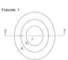
- the island shape in Figures 1-5 is shown to be elliptical in plan view, but in fact can take any regular or freeform shape.
- the mesh material can be coated with a "soft-touch coating" comprised of a spray-on elastomer such as latex or polyurethane. The purpose of the coating is to provide a less abrasive or non-abrasive finish, and it can be applied in varying thickness depending upon the effect desired.
- Figure 1 is a top view of the nonwoven mesh embodiment of the present invention, which comprises a top layer 1, a middle layer 2, and a bottom layer 3.
- Figure 2 is a section view of Figure 1 taken at A-A showing a first embodiment of the nonwoven mesh island.
- Each of the layers 1, 2, 3 is comprised of water-permeable, nonwoven mesh material 4 (such as POLY-FLO filter material) that has buoyant nodules 5 manufactured into the mesh.
- the buoyant nodules 5 may be comprised of any suitable low-density material, such as closed cell polymer foam, polystyrene, cork, or hollow plastic balls.
- Holes 6 are cut into the top layer 1 and middle layer 2, and a potted plant unit 7 is installed in each hole.
- the layers are joined together with adhesive 8.
- the adhesive 8 may be any suitable material, such as hot-melt glue or polyurethane foam sealant (such as Dow Chemical's GREAT STUFF or FROTH-PAC foam sealant).
- the foam may alternately be comprised of organic material, for example, soy-based foam, as described in the Journal of American Oil Chemists' Society, Vol. 76, No. 10 (October 1999 ).
- the foam sealant provides buoyancy, adhesion and rigidity to the structure. The buoyancy of the island can be adjusted after installation by adding additional foam as required.
- Figure 3 is a section view of Figure 1 taken at A-A showing a second embodiment of the nonwoven mesh island.
- This embodiment is comprised of multiple layers of nonwoven polyester mesh, similar to what is shown in Figure 2 , except that flotation for this second embodiment is provided by floats 9 that are installed into the embodiment during assembly of the layers.
- the floats 9 may be made of any suitable material, such as hard plastic or plastic foam fish net floats.
- FIG 4 is a section view of Figure 1 taken at A-A showing a third embodiment of the nonwoven mesh island.
- This embodiment is comprised of multiple layers of nonwoven polyester mesh, similar to what is shown in Figure 2 , except that flotation for the third embodiment is provided by expanding foam sealant 10 (such as Dow Chemical's GREAT STUFF or FROTH-PAC foam sealant).
- the foam sealant 10 is injected as a pressurized liquid into and through the fibers of the nonwoven mesh material 4.
- the foam sealant 10 also bonds the layers together.
- FIG. 5 is a section view of Figure 1 taken at A-A showing a fourth embodiment of the nonwoven mesh island.
- This embodiment is comprised of multiple layers of nonwoven polyester mesh, similar to what is shown in Figure 2 , except that flotation for the fourth embodiment is provided by buoyant blocks 11.
- the buoyant blocks 11 are inserted into holes (not shown) that are cut through the layers of nonwoven material.
- the buoyant blocks 11 may be retained within the holes by a friction-tight fit, and they may be manually adjusted in the vertical direction (as indicated by the arrows). This feature is particularly useful for adjusting the buoyancy of the island to compensate for the changing weight of growing plants.
- Both the floats of Figure 3 and the buoyant blocks of Figure 5 may be optionally perforated to provide additional pathways for plant roots.
- FIG. 1 the island is shown as being comprised of three layers. In practice, the present invention may be comprised of a single layer or any number of multiple layers.
- Figure 6 illustrates a method of attaching the layers of nonwoven mesh.
- a standard landscaping pin 12 is pushed through a top layer 1, a middle layer 2, and a bottom layer 3.
- the end sections 13 of the pin 12 are then bent upwards into U-shapes as shown and allowed to penetrate the bottom layer 3 in a second location as shown.
- the landscaping pin 12 locks the layers together.
- One example of a commercially available landscaping pin is the eight-inch wire staple sold by North American Green of Evansville, Indiana.
- apertures for containing plants or flotation materials may optionally be cut, melted or otherwise formed into the mesh material during manufacture.
- a preferred method of forming apertures in the nonwoven mesh material is illustrated in Figure 7 .
- a hole-opening tool is fashioned from a steel spike 14 by cutting the head 15 off the spike 14.
- the lower section 16 of the spike is then inserted into a standard electric or air-powered drill 17.
- the lower section 16 is round in cross section, with a pyramid or cone-shaped end.
- the apparatus comprised of the drill 17 and lower section 16 is used to open holes into layers of nonwoven mesh by pushing the lower section 16 through the nonwoven mesh while rotating lower section 16 with the drill 17.
- the resulting cylindrically shaped holes can be used to inject adhesive foam or to install plants and seeds. If desired, a hole can be kept open by temporarily inserting another steel spike 14 into the hole, until the adhesive, plant, or seed is installed.
- This method of producing an opening in the mesh is superior to cutting a hole because it requires much less effort, is faster, and produces a temporary hole that contracts around any installed adhesive, plant, or seed. This method is superior to melting a hole because it does not produce noxious fumes.
- An example of a suitable steel spike is 3/8-inch in diameter and 12 inches in length, available from McMaster-Carr (part number 97033A320). Larger diameter holes may be opened by substituting a custom manufactured mandrel 18 for the lower section 16. Such larger holes may be useful for installing rooted plants.
- the nonwoven mesh material acts as a biological filter media in that it provides an ideal substrate for bacterial colonization and allows the free passage of water through the media.
- the bacteria form beneficial biofilms and enhance the removal of nitrate, phosphorous and other undesirable nutrients as the pond water passes through the media.
- This microbial bio-removal of nutrients, along with nutrient uptake by plants growing on the island, provides significant nutrient removal from pond water and thereby improves overall pond health. As the microbes utilize nutrients and multiply, some of these microbes become detached from the island matrix and are dispersed throughout the pond, where they continue to remove nutrients.
- the island acts as microbial "seed source" to provide nutrient-removal microbes throughout the pond.
- the rate of nutrient removal is dependent upon the flow rate or hydraulic loading that the floating island experiences.
- the pond water could be pumped and sprayed over the island, which would increase the mass removal rate for pond water nutrients (including the possibility for actually filtering out algae).
- the island could be inoculated with aerobic or anaerobic microorganisms, plus start-up nutrients, in order to provide for enhanced nutrient uptake from the pond.
- a wind-powered, wave-powered or solar-powered pump or similar mechanism could be added to increase the rate of water flow through the filter media. All of the above would enhance the performance of the island as a floating biofilter. Additional embodiments that take advantage of these unique capabilities of the nonwoven mesh material of the present invention are described below.
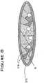
- Figure 8 shows a floating island comprised of scrap pieces of nonwoven mesh material 19, buoyant nodules 5, and an outer covering 20.
- the outer covering 20 may be fabricated by placing a bundle of mesh pieces 19 into a heatable mold (not shown). When the mold is heated to the melting point of the nonwoven mesh material (e.g., approximately 400° F for polyester), the outer fibers of the bundle soften and fuse, forming a porous "skin" around the unmelted center pieces of mesh material. The skin forms an outer covering 20 that confines the pieces of mesh material 19, while allowing water, plant stems, and plant roots to penetrate.
- the outer fibers of the bundle are softened and fused by applying a suitable solvent (e.g., di-octyl phosphate is a solvent for polyvinyl chloride mesh).
- a suitable solvent e.g., di-octyl phosphate is a solvent for polyvinyl chloride mesh.
- both heat and solvents may be simultaneously applied to form an outer skin on the bundle of mesh material.
- the outer covering 20 may also be comprised of a separate material, such as nylon netting.
- Figure 9 shows a floating island comprised of an upper section of relatively tightly packed nonwoven mesh 21 and a lower section of relatively loosely packed nonwoven mesh 22.
- the packing densities of meshes 21 and 22 are established during the manufacturing process of these materials.
- the packing density of the upper mesh 21 is selected so as to optimize it for plant root growth and durability.
- the packing density of the lower mesh 22 is selected so as to provide openings between the mesh fibers that offer security and feeding habitat for small baitfish 23, while excluding larger predator fish 24.
- small baitfish 23 is fathead minnows.
- Examples of predator fish 24 include bass and trout.
- Examples of foods that are consumed by baitfish within the lower mesh layer 22 include plant roots, phytoplankton and other algae.
- the habitat provided by the lower mesh layer 22 results in a larger population of baitfish than would otherwise exist in the pond. This larger population of baitfish promotes water clarity by adding complexity to the food chain and utilizing nutrients for fish growth that would otherwise be used by algae.
- Figure 9 illustrates one way in which the floating island of the present invention can be configured to provide food and shelter for fish. Even the embodiments that do not include the looser mesh shown in Figure 9 have proven beneficial to fish populations. Specifically, it has been observed that fish living in ponds that contain the floating islands of the present invention actually grow bigger than fish that do not live in such ponds. The reason for this phenomenon is that the floating islands of the present invention provide food in the form of plant roots for fish to eat.
- FIG 10 is a schematic illustration of an alternative embodiment of a floating island that uses nonwoven mesh as a protective barrier for small fish.
- the island shown in Figure 10 is comprised of a relatively tightly packed nonwoven mesh top layer 21, a relatively thin, loosely packed nonwoven mesh bottom layer 22, and buoyant spacers 25 to separate layers 21 and 22.
- the packing density of the mesh in the lower layer 22 is selected so as to allow small fish 23 to swim through layer 22 and into water pockets 26 that are located between layers 21 and 22.
- the water pockets 26 provide safe resting and feeding habitats for the small fish 23.
- the thickness of the lower layer 22 can be minimized because layer 22 is acting as a barrier to large predatory fish rather than a habitat for small fish.
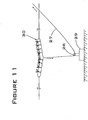
- Figure 11 illustrates an optional dunking feature that can be used in connection with the nonwoven mesh embodiments of the floating island discussed above.
- Figure 11 is a section view of the island shown in a partially submerged or "dunked" position.
- the dunking feature is comprised of a flexible line 27, a pulley 28, and an anchor block 29.
- the purpose of this feature is to provide water to the roots of the island plants when these roots do not extend to the pond waterline (for example, when the plants are immature).
- This feature allows a person to wet the roots from shore without having to use a sprinkler. To wet the roots, the person on shore pulls on the flexible line 27, drawing it through the pulley 28 in the direction shown by the arrows, and causing the island 30 to partially submerge. This action allows the water to enter the porous mesh of the island body.
- the flexible line 27 is released, the buoyancy of the island causes it to return to its normal floating position.
- FIG 12 is a section view of the island with optional "capillary action” features to provide water to plants that are growing above the natural waterline within the island.
- the capillary-action watering feature is comprised of capillary tubes 31 and an absorbent top cover 32. Pond water is drawn up through each capillary tube 31 (as shown by the directional arrows) and released to the absorbent top cover 32, where it is distributed to plants 33 growing above the waterline.
- the maximum vertical rise of water in the tubes is a function of the tube diameter and the physical properties of the water.
- h capillary rise (length)
- ⁇ surface tension (force per unit length)
- ⁇ wetting angle
- ⁇ specific weight of water
- r radius of tube
- the capillary tubes 31 can be fabricated from any suitable material, for example, flexible PVC tubing, semi-rigid polyethylene tubing, or rigid acrylic tubing.
- Figure 13 is a section view of the island with optional "wicking action" features.
- This embodiment is similar to the capillary-action watering feature of Figure 12 , except that the capillary tubes 31 are replaced by wicking units 34.
- the wicking units 34 are comprised of fabric or similar materials that have a significant wicking effect on water. In this embodiment, water is wicked up through the wicking units 34 and released to the absorbent top cover 32, where it is distributed to the plants 33.
- the wicking units 34 may be preferable to capillary tubes 31 for certain applications because they may enable a higher maximum water rise and may be less prone to bio-fouling.
- Hmax ⁇ LG * cos ⁇ * 2 * ⁇ - 2 / 100 * ⁇ LG * ⁇ / N 1 / 2 * Q * cos ⁇ + P R V * 1 - ⁇ * g * ⁇
- Hmax equilibrium suction height
- N number of fibers in bundle
- R V radius of fiber
- P % liquid from surface of bundle
- Q % non-wetted fibers from surface of bundle
- ⁇ filling
- p density of liquid
- the absorbent top cover 32 may be optionally planted with seeds, or coated with a mixture of seeds, adhesive, and nutrients. In either case, water will be delivered to the seeds via the capillary action shown in Figure 12 or the wicking action shown in Figure 13 .
- the mixture may be applied by any suitable means, such as "hydroseeding," wherein a mixture of seeds, paper mulch, and liquid adhesive is sprayed under pressure onto the surface of the island, after which it dries and adheres to the fibers of the island material.
- the capillary action of Figure 12 and the wicking action of Figure 13 occurs in connection with one of the nonwoven mesh embodiments of the present invention, but these innovations could be used with any floating island embodiment that includes living plants.
- Figures 14 and 15 depict another embodiment of the present invention in which the floating island includes bell-shaped flotation units.
- Figure 14 is a first section view of the floating island 35 with optional flotation "bells.”
- the bell flotation units are comprised of an air compressor 36, tubing 37, a solenoid valve 38, a control wire 39, one or more bells 40, and one or more internal spaces 41.
- the pond water level 42 is also shown.
- the bell flotation units are shown in a low-buoyancy position.
- Figure 15 is a second section view of the floating island 35 with optional flotation "bells" in a high-buoyancy position.
- a signal is sent via the control wire 39, which causes the solenoid valve 38 to open, thereby allowing any compressed air within the internal space 41 to vent to the atmosphere.
- the air pressure within the internal space 41 equalizes with atmospheric pressure, the water level within the internal space 41 will equilibrate with the pond water level 42.
- the arrow at the outlet of the solenoid valve 38 represents pressurized air that is escaping from the internal space 41 to the atmosphere.
- the flotation bells are providing minimum flotation to the island, and the island sinks to a relatively deep water level.
- a signal is sent via the control wire 39, which causes the solenoid valve 38 to shut.
- the compressor 36 is turned on, causing air to flow through the tubing 37 into the internal space 41.
- This air will raise the air pressure in the internal space 41, thereby forcing a portion of water out of the bottom of the bell 40 (in other words, displacing the water that is in the internal space 41).
- the buoyancy of the bell unit increases, thereby causing a net increase in buoyancy of the floating island, which causes the island 35 to rise partially out of the water.
- the water level can be set at any desired level between minimum and maximum by shutting off the compressor when the desired air volume in the internal space 41 is achieved.
- the bells 40 may be fabricated from any suitable material that is impermeable to air, strong, lightweight and durable. Suitable materials include, but are not limited to, thermoplastics such as polyethylene, foamed thermoplastics such as styrene foam, and closed cell foamed metals such as FOAMINAL, which is produced by Fraunhofer USA. Another material that shows promise for use in this application is foamed amorphous metal, which is currently being tested by LiquidMetal Corporation and other companies.
- the internal space 41 may optionally be filled with highly porous material that is permeable to both air and water.
- This highly porous material may be comprised of any suitable material, including, but not limited to, polyester mesh (such as POLY-FLO from Americo), open-cell foamed metal (such as DUOCEL foamed aluminum from ERG Materials and Aerospace), or open-cell foamed amorphous metal.
- polyester mesh such as POLY-FLO from Americo
- open-cell foamed metal such as DUOCEL foamed aluminum from ERG Materials and Aerospace
- open-cell foamed amorphous metal open-cell foamed amorphous metal.
- the bell flotation units provide a method for adjusting the overall buoyancy of the floating island, thereby allowing a person to manually adjust the draft of the island.
- This method can be used with any floating island embodiment.
- One advantage of this feature is that it provides a periodic water supply to plants and seeds that are located above the normal waterline, by temporarily lowering the island to a near-submerged position and then returning it to a normal position.
- Another advantage is that it adds buoyancy to the floating island to compensate for the negative buoyancy created by growing plants.
- Figure 16 shows a prefabricated seeding product that provides a rapid and easy means of seeding floating islands.
- the seed blanket 43 is mat-shaped, relatively thin and flexible, and may be rolled for storage and shipment.
- the seed blanket 43 is deployed by spreading it on top of a floating island and fastening it in place with landscaping pins (not shown) or other suitable fasteners.
- the seed blanket 43 is comprised of three layers, including a lower seed containment layer 44, a middle composite seed layer 45, and an upper seed containment layer 46.
- the composite seed layer 45 is comprised of selected aquatic plant seeds 47 and optional binder 48.
- the binder 48 may include adhesive and/or a moisturizing agent.
- the purpose of the lower containment layer 44 is to prevent the seeds from falling through the mesh body of the island.
- the lower containment layer 44 may be comprised of any suitable material that retains the seeds while allowing plant roots to pass through.
- suitable materials for the lower containment layer include fine nonwoven polyester mesh (such as polyester air filter material), coarse woven cloth (such as cheesecloth), and thermoplastic elastomer ("TPE").
- fine nonwoven polyester mesh such as polyester air filter material
- coarse woven cloth such as cheesecloth
- thermoplastic elastomer TPE
- the purpose of the upper containment layer 46 is to prevent loss of seeds by air or water currents prior to the time they sprout and take root.
- the thickness and density of the upper containment layer 46 must not be so great as to prevent the sprouted plants from penetrating the upper containment layer 46 and being exposed to sunlight.
- suitable materials for the upper containment layer 46 include fine nonwoven polyester mesh (such as polyester air filter material), coarse woven cloth (such as cheesecloth), and TPE.
- the present invention encompasses a larger version of the floating island that is designed to support the weight of one or more persons.
- An advantage of this design is that plants growing on the floating island can be watered by walking around on the surface of the island, thereby temporarily causing a localized area of the island surface to be depressed to the water level.
- FIG 17 is a section view of a first alternative embodiment of the larger floating island.
- the floating island is comprised of nonwoven mesh material 4, buoyant nodules 5, supplemental flotation units 49, and stepping pads 50.
- the buoyant nodules 5 are designed to support the weight of vegetation and the above-waterline portion of the nonwoven mesh material 4.
- the supplemental flotation units 49 are each designed to support the weight of one person, and they may be comprised of any material that is suitably buoyant and durable. Examples of suitable materials for the flotation units include polyurethane foam sealant and closed cell polymer foam.
- the stepping pads 50 provide a non-slippery walking surface and indicate the allowable areas for walking, and they may be comprised of any material that is suitably durable and slip resistant. Examples of suitable materials for the stepping pads include outdoor carpeting and synthetic stones made of molded fiberglass.
- the buoyant nodules may or may not be necessary depending on the degree of buoyancy provided by the supplemental flotation units.
- Figure 18 is a section view of a second alternative embodiment of the larger floating island.
- the design of the island shown in Figure 18 includes the features of the island shown in Figure 17 , plus additional load distribution members 51.
- the load distribution members 51 distribute the person's weight to several of the supplemental flotation units 49, thereby reducing the distance by which the stepping pad would otherwise move downward. This reduction of downward displacement provides a more stable walking surface than the design shown in Figure 17 .
- the load distribution members can be made of any suitably durable, lightweight and rigid material. Examples of suitable materials for the load distribution members include PVC pipe and aluminum channels. Two additional materials that may be particularly well suited for this application are metal foam and amorphous metal foam (currently in the development phase). Compared to thermoplastics, these two materials exhibit extremely high strength-to-weight ratios and long-term durability.
- the load distribution members In order to provide the required load distribution (and thereby prevent local sagging) of the island surface due to point loads (such as persons) supported by the island, the load distribution members must have sufficient stiffness.
- the stiffness of a pipe is a function of the pipe diameter, the pipe wall thickness, and the bending modulus of the pipe material.
- useful pipe diameters may range from about one inch to about 18 inches; useful wall thickness may range from about 1/16 inch to about one inch; and useful bending modulus may range from about 5,000 pounds per square inch (psi) to 500,000 psi, as measured by ASTM Standard D747-02.
- the islands shown in Figures 17 and 18 may be assembled on-site near the water edge.
- the islands may be deployed by pushing or pulling the islands into the water with a truck or other mechanized equipment.
- the edge of the island coming into contact with the truck or other mechanized equipment may be reinforced with a load-bearing and/or load-distributing protective cover (not shown).
- This cover may be comprised of semi-rigid thermoplastic, such as polypropylene or PVC sheeting.
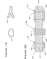
- Figure 19 shows top views of an artificial stepping stone 52 and artificial tree limb 53. These items may be manufactured form any buoyant, rigid and durable material, such as CAST ALL, which is a two-part expandable polymer foam available from Westco Supply in Ranch Cordova, California.
- CAST ALL is a two-part expandable polymer foam available from Westco Supply in Ranch Cordova, California.
- Figure 20 shows three alternative methods for using the artificial stepping stone 52 and artificial tree limb 53 that are shown in Figure 19 .
- the stepping stone flotation assembly 54 is comprised of a lower stepping stone 55, an upper stepping stone 56, and a connecting cable unit 57, which firmly attaches the stepping stones 55, 56 to the island body 58.
- the island body 58 may be comprised of any of the types of islands that have been previously described.
- the connecting cable unit 57 may be comprised of plastic rope or rustproof metal cable.
- the stepping stone/vertical buoyant member flotation assembly 59 is comprised of an artificial stepping stone 52 and a vertically installed buoyant member 60.
- the buoyant member 60 may be comprised of air-filled or closed cell foam-filled plastic pipe or other similar material.
- the buoyant member 60 may be attached to the island body 58 by adhesive (not shown), cable ties (not shown) or other conventional means.
- the floating tree limb assembly 61 is comprised of a lower artificial tree limb 62, an upper artificial tree limb 63, and a connecting cable assembly 57.
- the lower tree limb 62 is normally submerged, thus providing buoyancy to the island structure. Additional buoyancy is provided to the structure when the upper tree limb 63 is also partially or fully submerged.
- the buoyant components the stepping stones 52, 55, 56 and the tree limb 53, 62, 63
- conventional buoyant building materials such as closed cell foam blocks or cylinders (not shown).
- the natural shapes of the stepping stones 52, 55, 56 and tree limbs 53, 62, 63 provide aesthetic appeal to the structure.
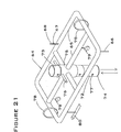
- Figure 21 is a perspective view of a framework that could be used in conjunction with any floating island structure to provide adjustable buoyancy. In the preferred embodiment, it is used in connection with the nonwoven mesh island.
- Figure 21 shows the horizontal and vertical components of a variable buoyancy, rigid framework 64.
- the horizontal members 65 are comprised of hollow plastic pipe or other similar material. These horizontal members 65 may be installed either below or within the mesh matrix body of the island (not shown).
- the overall buoyancy of the structure is designed so that the horizontal members are set below the waterline.
- the buoyancy of the horizontal members 65 can be adjusted by filling the interior space of the members with water, air, or a combination of both.
- water enters the horizontal members 65 via a water tube 66 when the air control valve 67 is open to the atmosphere.
- Water can be displaced from the horizontal members 65 by blowing compressed air into the air tube 68, thereby forcing water out through the water tube 66. After the water is displaced, the air control valve 67 is closed, which prevents water from reentering the structure.
- the horizontal members can be filled with foam to increase buoyancy. The buoyancy of the island can also be increased by adding additional horizontal members.
- the horizontal members are comprised of a perforated pipe section 69 and an inner, inflatable bag 70.
- the central portion of the pipe section 69 has been removed to show the inflatable bag 70.
- the inflatable bag 70 is shown in a deflated state, which allows water to enter the perforate pipe through holes 71.
- the horizontal members are in a low-buoyancy condition.
- an air control valve 67 is opened, and compressed air is forced through an air tube 68 into the inflatable bag 70.
- water is forced out of the pipe through the holes 71, thereby causing an increase in buoyancy.
- the air control valve 67 can be closed. This embodiment may provide a more reliable method of varying the buoyancy of the horizontal members than simply filling the pipes with air because the inflatable bag 70 will maintain buoyancy even if the pipes sustain cracks or leaks over time.
- the pipes 69 serve as a protective cover for the inflatable bag 70 against puncture and abrasion damage from floating debris and animals.
- additional adjustable buoyancy is provided to the rigid framework 64 via the lower vertical member 72 and the upper vertical member 73, which are comprised of hollow plastic pipe or similar material.
- the vertical members 72, 73 are joined with threads or another appropriate non-permanent connection.
- the vertical members can be joined permanently.
- the interior of the vertical members 72, 73 may be left open or optionally filled with buoyant material such as expandable foam sealant (e.g., Dow Chemical's FROTH-PAC).
- the lower end of the lower vertical member 72 is sealed with a watertight end cap 74.
- the buoyancy of the framework 64 is adjusted by sliding the vertical members 72, 73 upward or downward within the collar 75, as shown by the arrows.
- the lower vertical member can be raised to the maximum height and locked into position with a locking pin 76, which is placed through the locking pin holes 77. If desired, the upper vertical member 73 may be detached from the lower vertical member 72.
- the locking pin 76 is removed and the vertical members 72, 73 are pushed downward, deeper into the water. The vertical members are then locked into the new position via the locking pin 76. If required, an additional vertical member (not shown) may be connected to the top of the upper vertical member 73, and the vertical members may be positioned even deeper into the water. Locking straps 78 are used to keep the framework 64 attached to the mesh matrix body of the island (not shown).
- the framework 64 provides a rigid, load-distributing understructure, which can help to support the weight of persons walking on the island.
- the design of the framework 64 allows the buoyancy to be evenly distributed across the surface of the island, thereby eliminating "high spots” and "low spots” that would otherwise be produced by unconnected buoyant nodules located within the island body.
- Launching the floating island structure from shore into the water after construction may be facilitated by adding optional wheels 79 and/or skids 80 to the horizontal members 65 of the framework.
- the wheels and/or skids are preferably buoyant. If the horizontal members are sufficiently rigid, they can serve as skids, thus facilitating the launch of the island into the water without damaging the matrix and eliminating the need to add separate skids.
- FIG 23 shows yet another embodiment of an adjustably buoyant framework for a floating island.
- the framework is comprised of prefabricated flotation tubes 81and prefabricated cross members 82.
- Each flotation tube 81 is comprised of protective pipe 83, an inflatable tube 70, an air tube 68, and an air control valve 67.
- Each prefabricated cross member 82 is comprised of a strap 84, a plurality of pipe positioning devices 85, and a plurality of island body attachment posts 86.
- the purpose of the flotation tubes 81 is to provide buoyancy to the island structure and rigidity to the island surface.
- the purpose of the cross members 82 is to maintain the flotation tubes at the proper spacing, to provide additional rigidity to the island surface, and to provide a means for attaching the framework to the body of the island.
- the purpose of the protective pipe 83 is to prevent damage to the inflatable tube 70.
- the purpose of the inflatable tubes 70, air tube 67, and air control valves 68 is to provide a means for independently varying the buoyancy of each flotation tube 81, thereby providing an adjustable buoyancy across the surface of the island that can be used to compensate for varying and non-uniform loads that are placed (or grow upon) the island.
- the buoyancy in each flotation tube 81 is increased by increasing the degree of inflation in the inflatable tube 70, which displaces water from the inside of flotation tube 81.
- the buoyancy is decreased by reducing the degree of inflation in inflatable tube 70, thereby allowing water to enter flotation tube 81.
- the cross members 82 are manufactured in several standard lengths, such as five feet, ten feet and fifteen feet.
- the straps 84 may be comprised of any relatively stiff and corrosion-resistant material, such as galvanized steel channels, aluminum tubing or rigid plastic tubing.
- the pipe positioning devices 85 are attached in pairs to the straps 84 by conventional means, with a positioning device 85 on each side of a pipe 83.
- the island body attachment posts protrude through holes cut into the island body (not shown). Nuts and washers (not shown) are used to secure the island body to the attachment posts 86.
- the flotation tubes 81 can be manufactured in several standard lengths, such as five feet, ten feet and fifteen feet. They are comprised of materials as previously described in connection with Figure 22 .
- the framework depicted in Figure 23 can be quickly assembled to fit any freeform island shape by using an appropriate assortment of prefabricated flotation tubes 81 and cross members 82.
- the cross members 82 can alternatively be positioned above the flotation tubes 81.
- This configuration provides a flat base for the island body.
- the pipe positioning devices 85 are shown in this figure to be comprised of bracket-types fixtures, any conventional positioning fixture could be used.
- the cross members are shown to be rectangular in cross section, other cross section shapes, such as angles, channels or tubing could be used.
- Figures 24 and 25 illustrate two different methods for adding buoyancy to an island whose overall buoyancy has decreased over time due to plant growth or other conditions. If desired, these methods may be employed without removing the island from the water.
- Figure 24 shows a section view of an island with single attachment point flotation units 87.
- the left and center flotation units 87 utilize barbed spikes 88 for attachment.
- the barbed attachment spikes 88 may be made from corrosion-resistant metal, such as aluminum, or rigid plastic, such as PVC.
- the floats 89 may be commercially available fish net floats or similar objects made form any suitably buoyant and durable material.
- the spikes 88 are positioned within a hole inside the floats 89.
- the left flotation unit 87 in the figure is shown prior to attachment to the island body 58.
- the arrow shows the direction of movement required to push the flotation unit 87 into the bottom of the island body 58.
- the barb on the head of the spike 88 allows the flotation unit 87 to be pushed into the mesh material of the island body 58, thereby preventing the flotation unit 87 from slipping out.
- the center flotation unit 87 is shown in the attached position after the barb has been inserted into the island body 58.
- the right flotation unit 87 is shown attached to an artificial rock or other buoyant feature 90 by means of a retaining pin 91.
- a dual-ring buoy 92 is attached to landscaping pins 12 by means of conventional snap-on connectors 93.
- the landscaping pins 12 may be installed into the island body 58 during original construction, or they may be installed subsequent to construction of the island.
- Figure 26 illustrates the use of receivers for mounting equipment or accessories on the floating island of the present invention.
- a fully penetrating receiver unit 94 is shown installed into the left portion of an island body 58.
- the fully penetrating receiver unit 94 is comprised of a length of pipe 95, a lower flange 96, and an upper flange 97.
- the pipe 95 may be joined to flanges 97, 98 via threaded end connectors or glue joints.
- the pipe 95 is installed through a hole (not shown) that is cut, drilled or otherwise fabricated in the island body 58.
- a partially penetrating receiver unit 98 is shown on the right side of the island body 58 and is comprised of an upper flange 97 and a length of pipe 95 that does not penetrate the lower edge of the island body 58.
- the main purpose of the receiver units 94, 98 is to provide a mounting location for equipment or accessories such as solar panels, wind generators, or decorative items (not shown) that may be desirable for a particular island configuration.
- a plurality of receiver units 94, 98 may be installed on an island.
- a secondary purpose of the receiver units 94, 98 is to provide a means for locking together multiple layers of material within the island body.
- Figure 27 illustrates a method of using the floating island of the present invention to bolster a shoreline.
- the protective floating structure 99 is comprised of nonwoven mesh matrix 4, buoyant nodules 5, and optional plants 33.
- a conventional anchor or tether (not shown) may be used to maintain the position of the structure 99 relative to the shoreline 100.
- the structure 99 can be used to prevent erosion to the shoreline 100 by serving as an energy-absorbing damper to waves 101.
- the structure 99 can also serve as a protective barrier to prevent floating objects (such as boats or logs, not shown) from striking the shoreline 100.
- the depth of the floating island can be adjusted to accommodate whatever level of shore or bank erosion protection is desired.
- additional thin and lightweight island modules may be attached around the perimeter of the main central floating island in order to provide additional shade and plant growth area, thereby increasing the water quality benefits of the island.
- These additional island modules can be made of a single layer of nonwoven mesh material or similar suitable material, impregnated with buoyant material. While the central floating island could support larger plants, these "satellite" module islands could support short plants such as grasses and sedges.
- any of the embodiments of the present invention could be combined with artificial vegetation, if desired, for additional cosmetic effect.
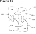
- Figure 28 shows a group of identical, mass-produced floating islands (made of nonwoven mesh material) that are connected to form a single large island.
- Figure 28 is a top view of four identical, mass-produced islands 102 that are joined with four connectors 103 to form a modular island structure 104.
- the connectors 103 are comprised of nonwoven matrix material.
- the connectors 103 may optionally be treated with bonded growth medium (described below) or other materials to promote plant growth.
- the plant-sustaining ability of the connectors 103 contributes to the visual appeal and biological diversity of the structure, while the mass-produced islands 102 provide a cost-effective manufacturing technique.
- FIG. 29 shows a first island 105 from which the central portion has been removed, creating a second island 106 and a central opening 107 within the first island 105.
- the central portion of the second island 106 has similarly been removed, creating a third island 108 and a central opening 109 within the second island 106.
- Figure 29 provides a significant reduction in materials required for construction of islands, thereby providing a significant cost saving for manufacture.
- Figure 29 shows a total of three islands, this number will vary depending on the size of the first island 105 and the desired size of the last island.
- Figure 30 shows a perspective view of a skeleton frame island 110 created by using the multiple concentric cutout method.
- the skeleton frame island 110 is comprised of a skeleton frame 111, a floor 112, one or more optional dividers 113, and buoyant intrusions 114.
- the skeleton frame, floor and dividers are all preferably comprised of nonwoven mesh material.
- Figure 31 shows a section view of skeleton frame island 110 taken at line B-B of Figure 30 .
- the skeleton frame island 110 is comprised of skeleton frame 111, floor 112, divider 113, buoyant intrusions 114, soil growth medium 115, soil-based plants 116, and matrix-based plants 117.
- Matrix-based plants are plants that are grown on portions of the island that are comprised of the nonwoven mesh material.
- the matrix-based plants may be started from either seeds or rooted plants that are installed into the matrix. Seeds may be sprinkled onto the top of the matrix and may optionally be bonded to the matrix fibers with any suitable adhesive. Rooted plants are installed into precut holes within the matrix.
- the soil growth medium 115 is comprised of natural organic material 118, such as peat, and of synthetic organic material 119, such as pieces of nonwoven polyester scrap material. Bonded growth medium (not shown, described more fully below) may be infused into the skeleton frame 111, floor 112, and/or divider 113. The bonded growth medium provides a durable environment for seed germination and plant growth.
- the relative growth rates of soil-based plants 116 and matrix-based plants 117 may be controlled by adjusting the nutrient concentrations and interstitial spacings of the soil growth medium 115 and skeleton frame 111. For example, by setting the nutrient level in the soil growth medium 115 higher than the nutrient level in the skeleton frame 111, the roots of the matrix-based plants 117 will grow faster, while the tops of the soil-based plants will grow faster. Similarly, plant growth rates may be manipulated by adjusting the percentage of interstitial space in the soil growth medium 115 and skeleton frame 111. For example, adding more synthetic organic material 119 to the natural organic material 118 will increase the volume of interstitial spaces within soil growth medium 115, thereby increasing the growth rate of microbes and macrophytes within the soil growth medium 115.
- the growth rates of plant roots on different zones of the island can be manipulated to improve the value of the island for fish and wildlife habitat.
- the nutrient levels in the perimeter zone are set at a relatively low level by using bonding agents without added nutrients around the perimeter, while the nutrient levels in the center soil growth medium area are set at a relatively high level by placing nutrient additives into the soil growth medium mixture.
- the roots of plants in the perimeter zone will grow rapidly through the matrix into the pond water in search of nutrients, thereby forming an underwater perimeter "curtain" of roots.
- the roots of plants in the central nutrient-rich soil growth medium zone will be able to obtain sufficient nutrients from a relatively small root mass; therefore, these roots will be slow to penetrate through the matrix into the water below.
- an underwater root zone will be formed under the island that has a relatively long, dense outer ring and a relatively short, slender-root center area. This embodiment will be attractive to small fish that seek refuge and food within the inner area because larger predator fish will be excluded by the outer ring.
- the skeleton-frame island embodiment of the present invention is capable of supporting plant growth over its entire surface area, while conventional "floating planters" have a non-permeable flotation ring around their perimeter that is not capable of supporting plant growth.
- the ability of the skeleton frame island embodiment of the present invention to support plant growth over the entire surface offers significant advantages for water-quality applications, as well as providing a more natural, visually appealing appearance than conventional floating planters.
- Nonwoven mesh scrap material from the cutting and shaping of the skeleton frame 111 and floor 112 may provide a low-cost source of synthetic organic material 119. Adding synthetic organic material 119 will also reduce the saturated weight of the soil growth medium 115, thereby reducing the volume of buoyant intrusions 114 required to float the skeleton frame island 110.
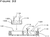
- Figure 32 shows two alternative embodiments for installing plants and soil growth medium into a skeleton frame island.
- Figure 32 is a side section view of a skeleton frame island 110 with two growth compartments 120 and 121 separated by a divider 113, and a prefabricated planter unit 122 shown prior to installation.
- the first growth compartment 120 is filled by placing soil growth medium 115, plants 116 and seeds (not shown) into the growth compartment 120 by hand.
- the second growth compartment 121 is filled by placing a prefabricated planter unit 122 into the compartment as shown by the arrow.
- the prefabricated planter unit 122 may be grown and shipped separately from the skeleton frame island and installed at the deployment site.
- the prefabricated planter unit 122 may have certain advantages, including the ability to culture plants professionally prior to installation, easy installation and replacement, and cost savings.
- the prefabricated planter unit 122 is comprised of a shell 123, soil growth medium 115, optional plants 116 and optional seeds (not shown).
- the shell 123 is comprised of a material such as coir or nonwoven polyester matrix that is permeable to water and penetrable by plant roots.
- the soil growth medium 115 may include pH buffers and modifiers to optimize plant growth for specific conditions.
- the soil growth medium can comprise calcium carbonate or other similar substance that increases the pH of the water surrounding the plant roots, thereby giving these roots an optimized growth environment during their early growth stage.
- substances that reduce the pH of water can be added to the soil growth medium 115 when an island is deployed in alkaline waters with plants that prefer neutral or acidic pH.
- Peat is an example of a material that can provide an acidic pH environment.
- the present invention also encompasses a bonded growth medium that is optimized for germinating and nurturing plants in an aquatic setting.
- the bonded growth medium of the present invention is designed specifically to be used as a component of a floating island, although it may be used in other applications as well.
- the bonded growth medium encompasses a number of optional features to optimize it for various conditions and for use with a variety of plant species.
- the bonded growth medium is described below as used with islands comprising a continuous matrix top surface, but can be equally well employed with the skeleton frame island embodiment.
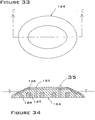
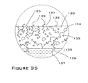
- Figure 33 is a top view of a floating island 124 with bonded growth medium, shown prior to plant growth.
- Figure 34 is a section view of the first embodiment of the bonded growth medium taken at section C-C of Figure 33 , in which the bonded growth medium 125 is attached to the outer surface of the floating island 124.
- the island 124 shown in Figure 34 is comprised of bonded growth medium 125, porous matrix 126, buoyant inclusions 127, and optional capillary channels 128.
- Porous matrix 126 may be comprised of any lightweight, porous material penetrable by plant roots.
- An example of a suitable material is POLY-FLO filter mesh, manufactured by Americo.
- Buoyant inclusions 127 may be comprised of any nontoxic buoyant material, such as closed cell foam or polyurethane spray foam.
- Capillary channels 128 are vertical holes cut into the matrix 126 and filled with any suitable wicking material. The purpose of the capillary channels 128 is to transport water through the island matrix 126 and supply it to the bonded growth medium 125 on the top and edges of the island.
- the wicking material in the capillary channels 128 is comprised of peat, polyester felt, or other suitable natural or synthetic material.
- the capillary channels 128 are filled with bonded growth medium.
- the bonded growth medium 125 is comprised of peat fibers (or similar material) 129, binder 130, optional embedded seeds 131, optional topcoat seeds 132, optional nutrient particles 133 and optional buoyant pellets 134.
- Other optional materials include shredded paper, shredded wood, and lightweight synthetic materials.
- Beneficial microbes (not shown), which include fungi and bacteria, may also be optionally included in the bonded growth medium.
- the water retention, buoyancy, nutrient level, pH, porosity, interstitial space volume, and other parameters can be modified to optimize for a specific type of plant (e.g., aquatic versus flowering terrestrial), a particular water body (e.g., alkaline or acidic), a particular island shape (e.g., low-floating versus high-floating), or even to create an optimal environment for the growth of beneficial microbes.
- a specific type of plant e.g., aquatic versus flowering terrestrial
- a particular water body e.g., alkaline or acidic
- a particular island shape e.g., low-floating versus high-floating
- the first purpose of the peat fibers 129 is to retain water and absorb radiant sunlight energy, thus providing optimal conditions for plant germination and growth.
- the second purpose of the peat fibers 129 is to provide a natural, visually appealing surface.
- a third purpose of the peat fibers is to prevent sunlight from contacting the fibers within the matrix, thereby preventing the growth of algae within the matrix.
- a fourth purpose of the peat fibers is to reduce the pH of water adjacent to plant roots.
- the purpose of the binder 130 is to attach the peat fibers 129 and seeds 132, 133 to the matrix 126, and to prevent them from being lost due to wind or wave action.
- Nutrient particles 133 may be comprised of commercial slow-release plant fertilizer or similar material.
- Buoyant pellets 134 may be comprised of perlite, polystyrene, or other lightweight closed cell materials. The buoyant pellets provide additional buoyancy to the structure if required for a particular application.
- the first purpose of the bonded growth medium 125 is to provide an optimal growth environment for seeds and plants.
- a second optional purpose of the bonded growth medium 125 is to provide a low-permeability gas barrier around the outer surface of the island, thereby trapping within the body of the island water vapor and gases produced by microbes. The water vapor minimizes "air pruning" of plant roots, and the other gasses provide additional buoyancy to the island structure.
- the bonded growth medium 125 also serves as a protective agent to prevent deterioration of the matrix 126 and buoyant inclusions 127 by ambient ultraviolet ("UV") sunlight.
- UV ambient ultraviolet
- the UV protection may be provided by the natural light-absorbing qualities of the peat fibers or similar material 129, or the UV protection of the bonded growth medium 125 can be boosted by adding a UV-blocking agent to the uncured bonded growth medium mix prior to application.
- a suitable common UV-blocking agent is carbon black.
- the binder 130 is comprised of a porous and permeable material, such as open cell polyurethane foam or cellulose (similar to kitchen sponges).
- the binder transports water to the seeds 131, 132 and plants (not shown) from the capillary channels 128, or from the water body (not shown) in which the island is floating.
- the binder 130 is comprised of nonporous thermoplastic such as TPE or other nonporous, non-permeable binder material.
- the ratio of peat fibers 129 and binder 130 is designed so that the proportion of peat fibers 129 is sufficient to serve as the water transport medium through the bonded growth medium 125.
- the bonded growth medium 125 is preferably manufactured as a viscous liquid in the uncured state, which changes to a flexible solid after curing.
- the uncured bonded growth medium 125 is poured or sprayed over the top of the matrix and binds to the matrix 126 during the curing process.
- An infiltration zone 135 occurs where bonded growth medium 125 infiltrates into the matrix 126 prior to curing.
- the embedded seeds 131 may be added to the mixture during manufacture, and the topcoat seeds 132 may be sprinkled onto the uncured bonded growth medium 125 after it has been applied to the matrix 126.
- embedded seeds 131 may be installed via holes punched into the partially or fully cured bonded growth medium 125 after it has cooled sufficiently, and topcoat seeds 132 may be attached by a conventional nontoxic adhesive.
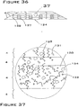
- Figure 36 shows an island 124 comprised of individual layers of nonwoven mesh material 4 that have been stacked and bonded together. Also shown are buoyant inclusions 127 and capillary channels 128, which are identical to those items previously described for Figure 34 . In this embodiment, the components of the bonded growth medium are embedded within the matrix layers 4 rather than being applied to the top of the matrix 126, as shown in Figures 34 and 35 .
- Figure 37 is a magnified view of a portion of Figure 36 , showing the components of the embedded bonded growth medium.
- Peat fibers (or similar material) 129, binder 130, optional embedded seeds 131, optional nutrient particles 133 and optional buoyant pellets 134 are all similar to the materials described in connection with Figure 34 .
- the embedded bonded growth medium shown in Figures 36 and 37 can be manufactured in at least three different ways.
- a first method involves incorporating the components of the bonded growth medium into the matrix layers 4during the manufacturing process of the matrix.
- the matrix layer 4 is comprised of nonwoven polyester mesh (e . g ., Americo's POLY-FLO)
- the peat fibers 129, nutrient particles 133 and buoyant pellets 134 may be added into the mixing hopper along with the raw polyester fibers. All of the materials are then bonded together when latex binder is added to the matrix.
- a second method of manufacturing the embedded bonded growth medium involves injecting the uncured bonded growth medium into each sheet of matrix prior to stacking. This method can be used in connection with nonwoven mesh materials such as Americo's POLY-FLO, which is typically supplied in two-inch thick sheets. Multiple layers of matrix sheets are stacked and bonded to make a floating island, as shown in Figure 36 .
- the uncured bonded growth medium may be injected into the matrix by pressure spray with optional vacuum assist applied to the back side of the matrix, by point injection via a tube inserted into the matrix, or by gravity infiltration of a low-viscosity blend of uncured bonded growth medium into the matrix.
- a third method of manufacturing the embedded bonded growth medium involves stacking the matrix layers prior to injecting the bonded growth medium. Injection is accomplished as described above.
- the bonded growth medium may act as an adhesive to bond the layers of matrix.
- a common feature of all of the nonwoven mesh material floating island embodiments of the present invention is that they can serve as a biofilter in at least two respects.
- the island exposes phosphorus and other nutrients found in pond water to the microorganisms (which can be anaerobic or aerobic) present on the island's polymer matrix and/or in the bedding matrix, growth medium, or plant roots. These nutrients help sustain the microorganisms, which contribute to pond and plant health.
- the island can also act as a means of dispersing certain beneficial microorganisms, including, but not limited to, fungi, throughout a pond or other water body.
- This dispersal of microorganisms is accomplished as the water that is filtered through the island carries off a fraction of the island's population of microorganisms.
- These beneficial microorganisms can be naturally occurring, or they can be introduced onto or into the floating island by artificial means.
- the plants that are grown on the island can be selected on the basis of their ability to contribute to the removal of phosphorus and other nutrients from the water body.
- the wetland plants that utilize phosphorus in large quantities include: Scirpus validus (Bulrush), Phragmites communis (common reed), and Typa latifola (cattail). Plant uptake of phosphorus during the algae growing season will reduce the amount of phosphorus available for algae production and thereby impact the eutrophication process. It is expected that the types of plants listed above, if grown on the floating island of the present invention, could reduce the overall phosphorus concentration in the water passing through the floating island by 40 to 70%.
- the amount of nutrients removed by this process will be proportional to the hydraulic loading rate for the island (i.e., the rate at which water passes through the island).
- Various mechanisms such as a water pump, could be used to increase the hydraulic loading rate and, therefore, the amount of nutrient removed.
- the structure of the island could be adjusted to take maximum advantage of its filtering capacity. For example, the profile of the island above the water surface could be increased to a higher level in order to provide a greater unsaturated volume of media through which water could be filtered.
- a water distribution system may be used to pump water from beneath the island and spread it across the surface of the island, allowing the water to percolate through the fibers of the island matrix (or the nonwoven mesh material) for biological treatment.
- Figure 38 is a schematic depiction of a first embodiment of a floating island 136 with a pumped water distribution system 137. The path of water flowing through the system is shown by arrows.
- the island 136 is comprised of nonwoven mesh 4 plus other materials (not shown).
- the water distribution system 137 is comprised of a water pump 138 and distribution pipes 139.
- Figure 39 is a top view of the water distribution system that shows schematically the distribution pipes 139.
- This particular water distribution system is designed to distribute water over the surface of the island while not restricting upward plant growth.
- the purpose of the water distribution system 136 is to pump untreated pond water from beneath the island and spread it across the surface of the island, whereby it can percolate through the fibers of the nonwoven mesh 4 for biological treatment. For maximum treatment efficiency, it is important to distribute the water throughout the entire volume of the nonwoven mesh 4.
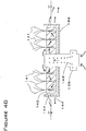
- Figure 40 is a section view of a second embodiment of a floating island with a pumped water distribution system.
- the system is comprised of a water pump 138, nonwoven mesh island body 140, nutrient-uptake aquatic plants 141, and water-impermeable enclosure tray 142.
- nutrient-uptake aquatic plants refers to aquatic plants that absorb and incorporate nutrients found in the water.
- cattail genus Typha .
- the system shown in Figure 40 works by pumping nutrient-rich pond water from beneath the island and circulating it radially outward through the island body 140.
- the path of the circulated water is indicated by the arrows in the figure.
- Optional air bubbles 143 may be provided from an external air source (not shown).
- the water pump 138 is shown as extending vertically through the center of the island, but the water pump 138 could be positioned in any manner that allows it to pump water through the island.
- the water flows through the island body 140 from the center toward the edges and exits the island body 140 through perforations 144 in the perimeter of the tray 142.
- the purpose of the tray 142 is to ensure that the flowing water does not escape through the bottom of the island, thereby maximizing its exposure time for uptake by the plants 141 and for treatment by microorganisms (not shown) that are attached to the fibers of the island body 140 and the roots of plants 141.
- the tray 142 is constructed of lightweight plastic, such as polyethylene, that is impermeable to both water and plant roots.
- the tray 142 is constructed of a material such as TPE that is impermeable to water but that is capable of being penetrated by growing plant roots. The island essentially sits in the tray, and the tray is attached to the floating island by any conventional fastening method.
- the purpose of the optional air bubbles 143 is to increase the rate of aerobic conversion of nutrients by microbes.
- the energy source for the compressed air (not shown) that produces these bubbles may be utility electricity, solar-electric, wind-mechanical, wind-electric, or other suitable means.
- the floating islands of the present invention can also facilitate the process of carbon sequestration, which has become the subject of relatively new international environmental policies that provide financial incentives for growing plants that sequester carbon.
- Carbon sequestering is accomplished by growing plants that uptake carbon dioxide from the atmosphere and convert it via photosynthesis to organic carbon within the plant. This process reduces the greenhouse effect of atmospheric carbon dioxide by reducing the concentration of carbon dioxide in the atmosphere.
- carbon dioxide is reduced by direct removal from the atmosphere by the plants, and it is also reduced by microbial processes occurring below the waterline within the root community and matrix of the islands.
- Floating islands offer a novel and unique means for sequestering carbon because they can be installed at locations where typical carbon-sequestering plants (e.g., pine trees) cannot thrive.
- the floating islands of the present invention can be positioned over nutrient-rich, oxygen-depleted marine zones, such as the "dead zone" in the Gulf of Mexico.
- the term "dead zone” generally refers to the situation in which nutrient-rich water flows into an ocean from a river, algae in the ocean water near the surface consume those nutrients and produce oxygen in the process, the algae cells eventually die and sink toward the bottom of the ocean, where the algae cells consume oxygen as they decay. Due to the large number of algae cells falling to the bottom of the ocean, all of the oxygen near the bottom is consumed, and there is no oxygen left in the water for fish, lobsters, or other animals, thus creating a "dead zone” near the ocean bottom. Within the dead zone, the water is nutrient-rich but oxygen-poor. Above the dead zone, near the ocean's surface, the water is both nutrient- and oxygen-rich.
- water from the dead zone can be pumped over the island (e.g., by windmills on the island), where it will provide nutrients to plants growing on the island.
- the plants on the island use sunlight energy to combine carbon dioxide from the air with nutrients in the water to make plant mass. This process removes carbon dioxide from the air (reducing the greenhouse effect) and sequesters the carbon in plant biomass.
- new water circulates into the dead zone to replace the water that has been pumped out. This process accomplishes two beneficial effects: reduction of the dead zone and carbon sequestration.
- the islands can be designed so that they are "self-growing” by selecting plants that will provide lateral expansion of the surface of the island during their normal growth and death cycle.
- Examples of marine plants that could create their own substrate and expand laterally include seaweeds of the genera Eucheuma and Kappaphycus.
- Examples of plants that may tolerate a saline environment include Sea Rush ( Juncus maritimus ), Sea Lavender ( Limonium latifolia ) and similar species.
- Another method that could be used to expand the surface area of the floating islands of the present invention involves a biological adhesive and bonding process, such as that described for the marine mussel Mytilus edulus in the book Biomimicry (Janine Benus, HarperCollins, 1997).
- the mussel produces cross-linked strands of protein with very high cohesive and adhesive properties, and the mussel-produced adhesive can be applied underwater.
- This adhesive material would be useful for bonding matrix fibers in the floating islands, for "growing” islands after deployment, and for trapping sediment particles from the water, thereby improving water clarity. "Growing the islands” could be accomplished by periodically dosing the edges of an island with biological adhesive.
- the adhesive remains sticky when wet, it would tend to catch debris such as grass, leaves and twigs floating in the water. This debris would adhere to the edges of the island and provide a substrate for plant growth, thereby causing the island to expand laterally.
- the adhesive would also trap fine waterborne and windblown sediment particles that contact the island.
- the biological adhesive could be manufactured by mussels or reproduced synthetically in a laboratory.
- Figure 41 illustrates a floating island that can also serve as a boat dock. This feature would be useful for docking at the islands for replanting, maintenance, hunting, fishing or photography.
- Figure 41 shows a top view of a floating island 145 constructed in a shape that is designed to provide a boat docking location 146.
- the boat docking location 146 is shaped so that the docked boat is mostly surrounded by island material.
- Low abrasion padding 147 such as closed cell polyethylene foam or fine nonwoven polyester mesh
- the integral boat-docking feature has several useful applications. First, it provides a safe location for storing boats during storms because the flexible nature of the nonwoven mesh island matrix provides an energy-absorbing support for the boat hull during periods of high waves and/or wind. Second, the boat docking area provides an efficient method of supporting the boat during egress and ingress of passengers who may be visiting the island for pleasure or maintenance. Third, the island can be used to provide additional docking facilities where existing docking space is limited or expensive. Fourth, the island can be used as a means for concealing a boat and passengers for hunting or wildlife photography purposes. Although the structure of Figure 41 is shown surrounded by water, the structure could alternately be attached to shore to act as a boat-docking pier.
- FIG. 42 illustrates an anchoring device that can be used with the floating island of the present invention.
- This figure is a top view of an anchor 148 that is designed to hold a floating island regardless of wind direction.
- the anchor 148 is comprised of four barbs 149 set at 90-degree angles to each other and four ring attachment points 150, as shown.
- the anchor is designed to be secured to an island with four tether lines (not shown) by attaching one end of each tether line to each ring attachment point 150. The other end of each tether line is secured to an attachment point along the perimeter of an island.
- Each barb 149 is designed to catch and hold onto the pond bottom when the direction of pull is opposite the direction of the point of the barb. By having a plurality of barbs 149 facing in different directions, at least one barb will be properly positioned for maximum holding ability regardless of the direction pull.
Abstract
Description
- This application claims the priority of
U.S. Provisional Application No. 60/574,121 filed on 24 May 2004 - The present invention relates to a super-enhanced, adjustably buoyant floating island that can be deployed in ponds, lakes, rivers or any other body of water to monitor, regulate and improve water quality, enhance plant and animal life, and complement the natural surroundings.
- In bodies of water such as ponds and lakes, algae growth and the natural process of eutrophication can lead to an increase in land mass and corresponding decrease in water volume, the killing of fish and other organisms, and the diminishment of aesthetic appearance. Various floating mechanisms have been devised with the aim of purifying water, cultivating plants, dispensing fertilizer, or counteracting the effects of eutrophication. None of these inventions anticipates the combination of features provided by the present invention.
-
U.S. Patent No. 5,799,440 (Ishikawa et al., 1998 ) discloses a floating island comprising: (i) a planter with holes in it to allow the roots of the plants to grow into the water and to supply water to the soil in the planter; and (ii) an oxygen-generating agent container attached to the bottom of the planter. The planter is made of a foamed resin with a reinforcing film of polyurethane elastomer on the surface. The invention also includes: (i) a layer of porous material on the inner surface of the bottom of the planter that has an aerobic microorganism immobilized in it; and (ii) a plant cultivation bag to hold the soil. In the preferred embodiment, the oxygen-generating agent is calcium peroxide, and the soil in the planter is covered with a net or fabric that is permeable to water and air and is not harmful to the plants. In addition to generating oxygen, calcium peroxide also eliminates phosphorus, thereby restricting algae growth. -
U.S. Patent No. 4,086,161 (Burton, 1978 ) sets forth an ecological system and method for counteracting the effects of eutrophication in bodies of water such as marshlands, inland ponds and lakes. The system uses clusters of bark fibers positioned in the upper, relatively oxygen-rich zones of such bodies of water. These bark clusters attract and hold excessive nutrient deposition in the form of colloidal wastes and aquatic algae and also provide a safe habitat for algae predators and feeders. -
U.S. Patent No. 6,086,755 (Tepper, 2000 ) provides a floating hydroponic biofiltration device for use in a body of water containing plant-eating fish. The invention includes a float, a mesh and a matting. The float contains an aperture devoid of soil in which a terrestrial plant is inserted. The mesh is at a substantial depth below the float and serves to enable passage of oxygenated water to the plant roots while excluding large plant-eating fish. The mesh also serves as a substrate surface for the growth of nitrogen-converting bacteria, which convert the ammonia of fish waste to nitrates useful to plants. The matting anchors the plant roots and partially excludes plant-eating fish from a portion of the plant roots. In the preferred embodiment, the mesh and matting are formed of plastic. -
U.S. Patent Nos. 5,766,474 (Smith et al., 1998 ) and5,528,856 (Smith et al., 1996 ) set forth a biomass impoundment management system that uses sunlight to purify water. The main purpose of this invention is to control impurities in water impoundments, such as ammonia, nitrogen, phosphorous and heavy metals. It is well known that nitrogen and phosphorous are a primary food source for various undesirable algae species, and ammonia and heavy metals are toxic to humans, fish and other organisms. This invention aims to purify water by allowing rooted bottom dwelling plants to grow and remain healthy on the bottom of a water impoundment while allowing rootless floating plants to grow and remain healthy above them. The non-rooted, floating plants are contained in a large surface area provided by elongated channels, which are oriented in a North-South direction to take full advantage of the sun. The elongated channels are designed to take advantage of wave activity to increase productivity. -
U.S. Patent No. 5,337,516 (Hondulas, 1994 ) sets forth an apparatus for treating waste water that includes a waste water basin and a number of wetland plants in floating containers. The idea underlying this invention is that the root systems of the wetland plants will treat the waste water. The extent of growth of the root systems is controlled by an adjustable platform associated with each floating container, so that the aerobic and anaerobic zones within the waste water basin are controlled and can be adjusted or varied as required. Similarly,U.S. Patent No. 5,106,504 (Murray, 1992 ) covers an artificial water impoundment system designed to remove biologically fixable pollutants from urban or industrial waste water using aquatic plants to absorb pollutants. -
U.S. Patent No. 4,536,988 (Hogen, 1985 ) relates to a floating containment barrier grid structure for the containment of floating aquatic plants in a body of water. This invention is designed to facilitate the commercial cultivation and harvesting of aquatic plants. The grid structure consists of elongated flexible sheets that are interconnected at spaced intervals along their longitudinal axes to form a plurality of barrier sections in a web-like arrangement. Through the use of an anchoring means, the barrier grid is tensioned so that certain portions of the structure are submerged beneath the surface of the water by a device that harvests the floating aquatic plants. -
U.S. Patent Nos. 4,037,360 (Farnsworth, 1977 ) and3,927,491 (Farnsworth, 1975 ) disclose a raft apparatus for growing plants by means of water culture or hydroponics. The raft floats on a nutrient solution, and buoyancy of the rafts is increased during plant growth by placing a small raft on a larger raft or on auxiliary buoyancy means.U.S. Patent No. 5,261,185 (Kolde et al., 1973 ) also involves an apparatus floating on a nutrient solution. In this invention, rafts are floated in a water culture tank filled with nutrient solution, plant containers are inserted in vertically oriented channels in the raft, and the plants are cultivated by gradually moving the raft from one end of the water culture tank to another. -
U.S. Patent No. 4,487,588 (Lewis, III et al., 1984 ) addresses a submersible raft for the cultivation of plant life such as endangered sea grasses. The raft is manufactured from standard polyvinyl chloride tubing and fittings. -
U.S. Patent No. 6,014,838 (Asher, 2000 ) discloses a simple floatable unit for decorative vegetation.U.S. Patent No. 5,836,108 (Scheuer, 1998 ) describes a floating planter box comprising a polyhedral planar base member of a synthetic foam resin less dense than water and an optional anchoring means. -
U.S. Patent Nos. 5,312,601 (Patrick, 1994 ) and5,143,020 (Patrick, 1992 ) involve a simple apparatus for dispensing fertilizer in a pond. The invention consists of a flotation structure surrounded by a porous material such as a net sack and an opening in the flotation structure through which fertilizer is dumped. The fertilizer is dissolved by water flowing through the net sack at the bottom of the flotation structure. - U.S. Patent Application Pub. No.
US 2003/0208954 (Bulk ) relates to a floating planter for plants and fish. The planter is made of closed cell plastic foam and includes recesses for above-water pot holders and a floating underside support for oxygenating underwater plants. The island has passageways downward through the island structure that open into the water and allow plant roots to reach the water. The island also has cavities that function as shelter for amphibious creatures such as frogs. - In addition to the patents and patent application discussed above, there are a number of patents and at least one published patent application that deal with growth medium for plants. For example,
U.S. Patent No. 5,207,733 (Perrin, 1993 ) involves the use of a low-density, rigid, unicellular (i.e., closed cell) expanded polyurethane foam that is perforated to facilitate the passage of emergent plant roots and to provide voids for water absorption and retention. -
U.S. Patent No. 2,639,549 (Wubben et al., 1953 ) describes a hydroponic growth medium that comprises a gravel bed that rests on a perforated bottom, which in turn rests on top of a ridged ground plate. A pump and gutters are used to circulate a nutrient solution throughout the gravel bed. -
U.S. Patent No. 5,224,292 (Anton, 1993 ) discloses a growth medium that consists of a layer of hollow nonwoven polyester fibers, wherein the lumens (or hollow insides) of the fibers contain a plant adjuvant (or something that assists plant growth), such as plant nutrients, fungicides, algaecides, weed killers and pesticides. -
U.S. Patent No. 6,615,539 (Obonai et al., 2003 ) provides a water-retaining support comprised of a hydrogel-forming polymer that is used as a plant growth medium. The object of the Obonai invention was to provide a hydrogel that would retain water without inhibiting plant root growth. - U.S. Patent Application Pub. No.
US 2003/0051398 (Kosinski ) involves a soil substitute that consists of fiberballs made of a biodegradable polymer fiber (for example, polyester) with a specific cut length and average dimension. The patent application includes a claim for a method of supporting plant growth by contacting plant material with the fiberball growth medium. - The present invention covers several different embodiments of a floating island comprising one or more layers of nonwoven mesh material. The present invention can be deployed in ponds, lakes, rivers or any other body of water to improve water quality, enhance plant and animal life, and complement the natural surroundings. Larger embodiments of the present invention may help prevent the greenhouse effect through carbon sequestration, which involves the removal of carbon dioxide from the atmosphere and the conversion of carbon to biomass. The larger embodiments of the present invention may also be used for farming or even habitation on or in bodies of water.
- The nonwoven mesh material of the present invention can be coated with a spray-on elastomer, inoculated with nutrients, or inoculated with aerobic or anaerobic microorganisms. The floating island can also comprise buoyant nodules that are manufactured into the mesh material or integrated into the,mesh material during assembly. The layers of mesh material can be joined together by an adhesive, and holes can be formed into the top layer or layers for plants or flotation materials. The island can include floats, buoyant blocks, a dunking feature, capillary tubes and/or wicking units. It can also include a top cover that is optionally biodegradable and that protects seeds that are either integrated into the top cover or placed underneath it.
- In an alternate embodiment, the floating island includes bell flotation units comprising an air compressor, tubing, a solenoid valve, a control wire and one or more bells. The bells can be formed of thermoplastic, closed cell foamed metal, amorphous metal, cement or plastic.
- The present invention also includes a larger embodiment that can bear the weight of one or more people. This larger embodiment is comprised of at least one layer of nonwoven mesh material, buoyant nodules, supplemental flotation units and stepping pads. This embodiment optionally includes one or more load distribution members or an adjustably buoyant framework comprising prefabricated flotation tubes and cross members. Other optional features include a stepping stone flotation assembly, a stepping stone/vertical buoyant member flotation assembly, and a floating log assembly. The buoyancy of the island can be adjusted with a rigid framework that comprises one or more horizontal members and, optionally, a water tube, an air control valve, and an air tube. The island can also include upper and lower vertical members that can be moved vertically within the island to further adjust its buoyancy.
- The present invention also covers a floating island with a boat docking location that is shaped so that the docked boat is mostly surrounded by island material. Low abrasion padding can be placed around the inner perimeter of the boat docking location to provide extra protection for the boat hull.
- Any of the embodiments of the present invention can be supplemented with additional island modules that are comprised of a single layer of nonwoven mesh material impregnated with buoyant material.
- The present invention also includes a prefabricated seed blanket that can be used to seed the island. It also includes a bonded growth medium for use in connection with the floating island of the present invention and several methods of manufacturing a floating island with the bonded growth medium of the present invention.
- The present invention encompasses a method of attaching various layers of nonwoven mesh material, a method of forming holes in the nonwoven mesh material, and a method of fabricating a floating island from scrap pieces of nonwoven mesh material. It also includes a method of constructing floating islands by creating multiple island cutouts from the nonwoven mesh material.
-
-
Figure 1 is a top view of the nonwoven mesh embodiment of the present invention. -
Figure 2 is a section view ofFigure 1 taken at A-A showing a first embodiment of the nonwoven mesh island. -
Figure 3 is a section view ofFigure 1 taken at A-A showing a second embodiment of the nonwoven mesh island. -
Figure 4 is a section view ofFigure 1 taken at A-A showing a third embodiment of the nonwoven mesh island. -
Figure 5 is a section view ofFigure 1 taken at A-A showing a fourth embodiment of the nonwoven mesh island. -
Figure 6 is a side view of a landscaping pin and a partial section view of a multilayered island showing a method of attaching the layers with a modified landscaping pin. -
Figure 7 is a side view of an apparatus used for opening holes into nonwoven mesh material without cutting or melting the mesh fibers. -
Figure 8 is a schematic illustration of a floating island fabricated from scrap pieces of nonwoven mesh material. -
Figure 9 is a side view of a floating island designed to provide security and feeding habitat for small fish. -
Figure 10 is a side view of an alternative embodiment of a floating island that uses nonwoven mesh as a protective barrier for small fish. -
Figure 11 is a section view of the island illustrating an optional dunking feature. -
Figure 12 is a section view of the island with optional "capillary action" features. -
Figure 13 is a section view of the island with optional "wicking action" features. -
Figure 14 is a first section view of an embodiment of the present invention with optional flotation "bells." -
Figure 15 is a second section view of an embodiment of the present invention with optional flotation "bells" in a high-buoyancy position. -
Figure 16 is a side section view of a prefabricated seed blanket. -
Figure 17 is a section view of a first alternative embodiment of a floating island designed to support the weight of one or more persons. -
Figure 18 is a section view of a second alternative embodiment of a floating island designed to support the weight of one or more persons. -
Figure 19 is a top view of an artificial stepping stone and an artificial tree log. -
Figure 20 is a section view of a floating island with stepping stones, artificial logs, and means for providing additional buoyancy. -
Figure 21 is a perspective view of the framework for a floating island containing both horizontal and vertical members. -
Figure 22 is a perspective view of an alternative embodiment of the island framework, in which the horizontal members are comprised of a perforated pipe and an inflatable bag. -
Figure 23 is a perspective view of an adjustably buoyant flotation framework that is comprised of prefabricated sections. -
Figure 24 is a section view of an embodiment of the present invention that includes single attachment point flotation units. -
Figure 25 is a section view of an embodiment of the present invention that includes a dual-ring buoy attached to the island with landscaping pins. -
Figure 26 is a section view of an embodiment of the present invention that includes receiver units. -
Figure 27 is a section view of an energy-absorbing and wave-damping floating structure made from nonwoven mesh material. -
Figure 28 shows a group of identical, mass-produced floating islands (made of nonwoven mesh material) that are connected to form a single island. -
Figure 29 shows a series of islands produced by the multiple concentric cutout method. -
Figure 30 shows a perspective view of a skeleton frame island created by using the multiple concentric cutout method. -
Figure 31 shows a section view of skeleton frame island taken at line B-B ofFigure 30 . -
Figure 32 shows two alternative embodiments for installing plants and soil growth medium into a skeleton frame island. -
Figure 33 is a top view of a floating island with bonded growth medium, shown prior to plant growth. -
Figure 34 is a section view of the first embodiment of the bonded growth medium taken at section C-C ofFigure 31 , in which the bonded growth medium is attached to the outer surface of the floating island. -
Figure 35 is a partial magnified view ofFigure 34 , showing the various components of the bonded growth medium. -
Figure 36 is a section view of a floating island comprised of individual layers of nonwoven mesh material that have been stacked and bonded together. -
Figure 37 is a magnified view of a portion ofFigure 34 , showing the components of the embedded bonded growth medium. -
Figure 38 is a side section view shown in schematic form of a water distribution system mounted on a floating island. -
Figure 39 is a top view of the water distribution system shown inFigure 38 . -
Figure 40 is a section view of a floating island optimized for use as a biotreatment system. -
Figure 41 is a top view of a floating island with an integral boat docking area. -
Figure 42 is a top view of an anchor that is designed to hold a floating island regardless of wind direction. -
- 1
- Top layer (nonwoven mesh embodiment)
- 2
- Middle layer (nonwoven mesh embodiment)
- 3
- Bottom layer (nonwoven mesh embodiment)
- 4
- Nonwoven mesh material
- 5
- Buoyant nodules (nonwoven mesh embodiment)
- 6
- Cut holes
- 7
- Potted plant units
- 8
- Adhesive
- 9
- Floats
- 10
- Foam sealant
- 11
- Buoyant blocks
- 12
- Landscaping pin
- 13
- Bent end section of landscaping pin
- 14
- Steel spike
- 15
- Head end of steel spike
- 16
- Lower end of steel spike
- 17
- Electric or compressed air drill
- 18
- Mandrel
- 19
- Scrap pieces of mesh material
- 20
- Outer covering
- 21
- Tightly packed nonwoven mesh
- 22
- Loosely packed nonwoven mesh
- 23
- Small fish or baitfish
- 24
- Large predator fish
- 25
- Buoyant spacers
- 26
- Water pockets
- 27
- Flexible line
- 28
- Pulley
- 29
- Anchor block
- 30
- Island (dunking embodiment)
- 31
- Capillary tubes
- 32
- Absorbent top cover
- 33
- Plants growing above waterline
- 34
- Wicking units
- 35
- Floating island ("bell" embodiment)
- 36
- Compressor
- 37
- Tubing
- 38
- Solenoid valve
- 39
- Control wire
- 40
- Bell (flotation)
- 41
- Internal space
- 42
- Pond water level
- 43
- Seed blanket
- 44
- Lower seed-containment layer
- 45
- Middle composite seed layer
- 46
- Upper seed-containment layer
- 47
- Aquatic plant seeds
- 48
- Binder
- 49
- Supplemental flotation unit
- 50
- Stepping pad
- 51
- Load distribution member
- 52
- Artificial stepping stone
- 53
- Artificial tree limb
- 54
- Stepping stone flotation assembly
- 55
- Lower stepping stone
- 56
- Upper stepping stone
- 57
- Connecting cable unit
- 58
- Island body (generic)
- 59
- Stepping stone/vertical buoyant member assembly
- 60
- Vertical buoyant member
- 61
- Floating tree limb assembly
- 62
- Lower artificial tree limb
- 63
- Upper artificial tree limb
- 64
- Variable buoyancy, rigid framework
- 65
- Horizontal members
- 66
- Water tube
- 67
- Air control valve
- 68
- Air tube
- 69
- Perforated pipe
- 70
- Inflatable bag
- 71
- Holes in perforated pipe
- 72
- Lower vertical member
- 73
- Upper vertical member
- 74
- Watertight cap
- 75
- Collar
- 76
- Locking pin
- 77
- Locking pin holes
- 78
- Locking straps
- 79
- Wheel
- 80
- Skid
- 81
- Prefabricated flotation tube
- 82
- Prefabricated cross members
- 83
- Protective pipe
- 84
- Strap
- 85
- Pipe positioning device
- 86
- Attachment post
- 87
- Flotation unit (single attachment point)
- 88
- Barbed attachment spike
- 89
- Float (single attachment point flotation unit embodiment)
- 90
- Buoyant feature
- 91
- Retaining pin
- 92
- Dual-ring buoy
- 93
- Snap-on connector
- 94
- Fully penetrating receiver unit
- 95
- Pipe (receiver unit)
- 96
- Lower flange
- 97
- Upper flange
- 98
- Partially penetrating receiver unit
- 99
- Protective floating structure
- 100
- Shoreline
- 101
- Waves
- 102
- Identical mass-produced islands
- 103
- Connectors (modular island)
- 104
- Modular island structure
- 105
- First island in multiple cutout design
- 106
- Second island in multiple cutout design
- 107
- Central opening within first island
- 108
- Third island in multiple cutout design
- 109
- Central opening within second island
- 110
- Skeleton frame island
- 111
- Skeleton frame
- 112
- Floor
- 113
- Divider
- 114
- Buoyant intrusions (skeleton island)
- 115
- Soil growth medium
- 116
- Soil-based plants
- 117
- Matrix-based plants
- 118
- Natural organic material
- 119
- Synthetic organic material
- 120
- First growth compartment
- 121
- Second growth compartment
- 122
- Prefabricated planter unit
- 123
- Shell (prefabricated planter unit)
- 124
- Island comprising bonded growth medium
- 125
- Bonded growth medium
- 126
- Porous matrix (bonded growth medium embodiment)
- 127
- Buoyant inclusions (bonded growth medium embodiment)
- 128
- Capillary channels (bonded growth medium embodiment)
- 129
- Peat fibers (or similar material)
- 130
- Binder
- 131
- Embedded seeds
- 132
- Topcoat seeds
- 133
- Nutrient particles
- 134
- Buoyant pellets
- 135
- Infiltration zone
- 136
- Floating island with pumped water distribution system
- 137
- Water distribution system
- 138
- Water pump
- 139
- Distribution pipes
- 140
- Nonwoven mesh island body (pumped filtration embodiment)
- 141
- Aquatic plants selected for nutrient uptake
- 142
- Enclosure tray
- 143
- Air bubbles
- 144
- Perforations (tray)
- 145
- Floating island (boat docking embodiment)
- 147
- Low-abrasion padding
- 148
- Anchor optimized for multiple wind directions
- 149
- Barb (anchor)
- 150
- Ring attachment point (anchor)
- The present invention is superior to any existing floating island-type technology because it provides a super-enhanced habitat for plants, improves water quality, discourages algae populations, slows the process of eutrophication, provides a habitat for fish and small animals, and is designed to be aesthetically pleasing. It is distinguishable from any of the patents reviewed above because it is designed to enhance the existing natural plant and animal habitat. Installation of the present invention does not require the draining of water, construction of a submerged substructure, fitting or alteration of a pond liner, or disturbance of existing flora or fauna. By virtue of its design, the present invention results in only minimal water displacement, which allows the pond or other water body to retain its carrying capacity and does not adversely affect the health of the water body.
- In a natural floating island, the roots of living plants are supported in a substrate composed mainly of other living roots, dead roots, and partially decomposed organic materials derived from dead plants and microbes. This natural substrate is mimicked by the island matrix of the present invention, whose rigid structure and porosity provide an ideal environment for the establishment of growing roots.
- In a natural floating island, microbial gas production provides a contribution to island buoyancy. In the present invention, the matrix fibers (nonwoven mesh) provide a large surface area for naturally occurring and introduced microbes that convert pond nutrients into gasses that provide buoyancy.
- In a natural floating island, the plants that have adapted successfully for island life generally provide their own buoyancy. For example, a fifty-foot tall larch tree can survive on a natural floating island because the buoyancy of the island in the vicinity of the tree is sufficient to support the weight of the tree; while a short distance away, the buoyancy of the island is only adequate to support the weight of two-foot tall leatherleaf plants. In each case, the plant roots and the biological community surrounding the roots provide adequate buoyancy to support the weight that is imposed by the above-water portion of the plant. Plants that cannot support their own weight are generally sparse on natural floating islands. In the present invention, plants with known self-generating buoyancy can be selected for use on islands where long-term, self-sustaining buoyancy is required.
- In a preferred embodiment of the present invention, the floating island is comprised of a nonwoven mesh material. This embodiment is shown in
Figures 1-5 . The island shape inFigures 1-5 is shown to be elliptical in plan view, but in fact can take any regular or freeform shape. In any of the nonwoven mesh embodiments, the mesh material can be coated with a "soft-touch coating" comprised of a spray-on elastomer such as latex or polyurethane. The purpose of the coating is to provide a less abrasive or non-abrasive finish, and it can be applied in varying thickness depending upon the effect desired. -
Figure 1 is a top view of the nonwoven mesh embodiment of the present invention, which comprises atop layer 1, amiddle layer 2, and abottom layer 3.Figure 2 is a section view ofFigure 1 taken at A-A showing a first embodiment of the nonwoven mesh island. Each of thelayers buoyant nodules 5 manufactured into the mesh. Thebuoyant nodules 5 may be comprised of any suitable low-density material, such as closed cell polymer foam, polystyrene, cork, or hollow plastic balls.Holes 6 are cut into thetop layer 1 andmiddle layer 2, and apotted plant unit 7 is installed in each hole. The layers are joined together with adhesive 8. The adhesive 8 may be any suitable material, such as hot-melt glue or polyurethane foam sealant (such as Dow Chemical's GREAT STUFF or FROTH-PAC foam sealant). The foam may alternately be comprised of organic material, for example, soy-based foam, as described in the Journal of American Oil Chemists' Society, Vol. 76, No. 10 (October 1999). The foam sealant provides buoyancy, adhesion and rigidity to the structure. The buoyancy of the island can be adjusted after installation by adding additional foam as required. -
Figure 3 is a section view ofFigure 1 taken at A-A showing a second embodiment of the nonwoven mesh island. This embodiment is comprised of multiple layers of nonwoven polyester mesh, similar to what is shown inFigure 2 , except that flotation for this second embodiment is provided byfloats 9 that are installed into the embodiment during assembly of the layers. Thefloats 9 may be made of any suitable material, such as hard plastic or plastic foam fish net floats. -
Figure 4 is a section view ofFigure 1 taken at A-A showing a third embodiment of the nonwoven mesh island. This embodiment is comprised of multiple layers of nonwoven polyester mesh, similar to what is shown inFigure 2 , except that flotation for the third embodiment is provided by expanding foam sealant 10 (such as Dow Chemical's GREAT STUFF or FROTH-PAC foam sealant). Thefoam sealant 10 is injected as a pressurized liquid into and through the fibers of thenonwoven mesh material 4. In addition to providing flotation, thefoam sealant 10 also bonds the layers together. -
Figure 5 is a section view ofFigure 1 taken at A-A showing a fourth embodiment of the nonwoven mesh island. This embodiment is comprised of multiple layers of nonwoven polyester mesh, similar to what is shown inFigure 2 , except that flotation for the fourth embodiment is provided by buoyant blocks 11. The buoyant blocks 11 are inserted into holes (not shown) that are cut through the layers of nonwoven material. The buoyant blocks 11 may be retained within the holes by a friction-tight fit, and they may be manually adjusted in the vertical direction (as indicated by the arrows). This feature is particularly useful for adjusting the buoyancy of the island to compensate for the changing weight of growing plants. Both the floats ofFigure 3 and the buoyant blocks ofFigure 5 may be optionally perforated to provide additional pathways for plant roots. - In
Figure 1 , the island is shown as being comprised of three layers. In practice, the present invention may be comprised of a single layer or any number of multiple layers.Figure 6 illustrates a method of attaching the layers of nonwoven mesh. InFigure 6 , astandard landscaping pin 12 is pushed through atop layer 1, amiddle layer 2, and abottom layer 3. Theend sections 13 of thepin 12 are then bent upwards into U-shapes as shown and allowed to penetrate thebottom layer 3 in a second location as shown. In this configuration, thelandscaping pin 12 locks the layers together. One example of a commercially available landscaping pin is the eight-inch wire staple sold by North American Green of Evansville, Indiana. - With respect to the embodiments shown in
Figures 1-5 , apertures for containing plants or flotation materials may optionally be cut, melted or otherwise formed into the mesh material during manufacture. A preferred method of forming apertures in the nonwoven mesh material is illustrated inFigure 7 . In this figure, a hole-opening tool is fashioned from asteel spike 14 by cutting thehead 15 off thespike 14. Thelower section 16 of the spike is then inserted into a standard electric or air-powereddrill 17. Thelower section 16 is round in cross section, with a pyramid or cone-shaped end. The apparatus comprised of thedrill 17 andlower section 16 is used to open holes into layers of nonwoven mesh by pushing thelower section 16 through the nonwoven mesh while rotatinglower section 16 with thedrill 17. The resulting cylindrically shaped holes can be used to inject adhesive foam or to install plants and seeds. If desired, a hole can be kept open by temporarily inserting anothersteel spike 14 into the hole, until the adhesive, plant, or seed is installed. - This method of producing an opening in the mesh is superior to cutting a hole because it requires much less effort, is faster, and produces a temporary hole that contracts around any installed adhesive, plant, or seed. This method is superior to melting a hole because it does not produce noxious fumes. An example of a suitable steel spike is 3/8-inch in diameter and 12 inches in length, available from McMaster-Carr (part number 97033A320). Larger diameter holes may be opened by substituting a custom manufactured
mandrel 18 for thelower section 16. Such larger holes may be useful for installing rooted plants. - All of the embodiments depicted in
Figures 1-5 share the same advantage in terms of biological filtration. The nonwoven mesh material acts as a biological filter media in that it provides an ideal substrate for bacterial colonization and allows the free passage of water through the media. The bacteria form beneficial biofilms and enhance the removal of nitrate, phosphorous and other undesirable nutrients as the pond water passes through the media. This microbial bio-removal of nutrients, along with nutrient uptake by plants growing on the island, provides significant nutrient removal from pond water and thereby improves overall pond health. As the microbes utilize nutrients and multiply, some of these microbes become detached from the island matrix and are dispersed throughout the pond, where they continue to remove nutrients. By this dispersal means, the island acts as microbial "seed source" to provide nutrient-removal microbes throughout the pond. The rate of nutrient removal is dependent upon the flow rate or hydraulic loading that the floating island experiences. The pond water could be pumped and sprayed over the island, which would increase the mass removal rate for pond water nutrients (including the possibility for actually filtering out algae). The island could be inoculated with aerobic or anaerobic microorganisms, plus start-up nutrients, in order to provide for enhanced nutrient uptake from the pond. A wind-powered, wave-powered or solar-powered pump or similar mechanism could be added to increase the rate of water flow through the filter media. All of the above would enhance the performance of the island as a floating biofilter. Additional embodiments that take advantage of these unique capabilities of the nonwoven mesh material of the present invention are described below. -
Figure 8 shows a floating island comprised of scrap pieces ofnonwoven mesh material 19,buoyant nodules 5, and anouter covering 20. Theouter covering 20 may be fabricated by placing a bundle ofmesh pieces 19 into a heatable mold (not shown). When the mold is heated to the melting point of the nonwoven mesh material (e.g., approximately 400° F for polyester), the outer fibers of the bundle soften and fuse, forming a porous "skin" around the unmelted center pieces of mesh material. The skin forms anouter covering 20 that confines the pieces ofmesh material 19, while allowing water, plant stems, and plant roots to penetrate. In an alternative method, the outer fibers of the bundle are softened and fused by applying a suitable solvent (e.g., di-octyl phosphate is a solvent for polyvinyl chloride mesh). Alternately, both heat and solvents may be simultaneously applied to form an outer skin on the bundle of mesh material. - The
outer covering 20 may also be comprised of a separate material, such as nylon netting. -
Figure 9 shows a floating island comprised of an upper section of relatively tightly packednonwoven mesh 21 and a lower section of relatively loosely packednonwoven mesh 22. The packing densities ofmeshes upper mesh 21 is selected so as to optimize it for plant root growth and durability. The packing density of thelower mesh 22 is selected so as to provide openings between the mesh fibers that offer security and feeding habitat forsmall baitfish 23, while excludinglarger predator fish 24. One example ofsmall baitfish 23 is fathead minnows. Examples ofpredator fish 24 include bass and trout. Examples of foods that are consumed by baitfish within thelower mesh layer 22 include plant roots, phytoplankton and other algae. The habitat provided by thelower mesh layer 22 results in a larger population of baitfish than would otherwise exist in the pond. This larger population of baitfish promotes water clarity by adding complexity to the food chain and utilizing nutrients for fish growth that would otherwise be used by algae. -
Figure 9 illustrates one way in which the floating island of the present invention can be configured to provide food and shelter for fish. Even the embodiments that do not include the looser mesh shown inFigure 9 have proven beneficial to fish populations. Specifically, it has been observed that fish living in ponds that contain the floating islands of the present invention actually grow bigger than fish that do not live in such ponds. The reason for this phenomenon is that the floating islands of the present invention provide food in the form of plant roots for fish to eat. -
Figure 10 is a schematic illustration of an alternative embodiment of a floating island that uses nonwoven mesh as a protective barrier for small fish. The island shown inFigure 10 is comprised of a relatively tightly packed nonwovenmesh top layer 21, a relatively thin, loosely packed nonwoven meshbottom layer 22, andbuoyant spacers 25 toseparate layers lower layer 22 is selected so as to allowsmall fish 23 to swim throughlayer 22 and intowater pockets 26 that are located betweenlayers small fish 23. With this embodiment, the thickness of thelower layer 22 can be minimized becauselayer 22 is acting as a barrier to large predatory fish rather than a habitat for small fish. -
Figure 11 illustrates an optional dunking feature that can be used in connection with the nonwoven mesh embodiments of the floating island discussed above.Figure 11 is a section view of the island shown in a partially submerged or "dunked" position. The dunking feature is comprised of aflexible line 27, apulley 28, and ananchor block 29. The purpose of this feature is to provide water to the roots of the island plants when these roots do not extend to the pond waterline (for example, when the plants are immature). This feature allows a person to wet the roots from shore without having to use a sprinkler. To wet the roots, the person on shore pulls on theflexible line 27, drawing it through thepulley 28 in the direction shown by the arrows, and causing theisland 30 to partially submerge. This action allows the water to enter the porous mesh of the island body. When theflexible line 27 is released, the buoyancy of the island causes it to return to its normal floating position. -
Figure 12 is a section view of the island with optional "capillary action" features to provide water to plants that are growing above the natural waterline within the island. The capillary-action watering feature is comprised ofcapillary tubes 31 and an absorbenttop cover 32. Pond water is drawn up through each capillary tube 31 (as shown by the directional arrows) and released to the absorbenttop cover 32, where it is distributed toplants 33 growing above the waterline. The maximum vertical rise of water in the tubes is a function of the tube diameter and the physical properties of the water. One equation that can be used to determine the required tube diameter for a given rise in water height is provided in Fluid Mechanics (see reference list) as Equation 2.12:
where h = capillary rise (length)
σ = surface tension (force per unit length)
θ = wetting angle
γ = specific weight of water
r = radius of tube - The
capillary tubes 31 can be fabricated from any suitable material, for example, flexible PVC tubing, semi-rigid polyethylene tubing, or rigid acrylic tubing. -
Figure 13 is a section view of the island with optional "wicking action" features. This embodiment is similar to the capillary-action watering feature ofFigure 12 , except that thecapillary tubes 31 are replaced by wickingunits 34. The wickingunits 34 are comprised of fabric or similar materials that have a significant wicking effect on water. In this embodiment, water is wicked up through the wickingunits 34 and released to the absorbenttop cover 32, where it is distributed to theplants 33. - The wicking
units 34 may be preferable tocapillary tubes 31 for certain applications because they may enable a higher maximum water rise and may be less prone to bio-fouling. One equation that can be used to determine the theoretical maximum rise due to fabric wicking is provided in the AUTEX Research Journal (see reference list) as follows:
where Hmax = equilibrium suction height
N = number of fibers in bundle
RV = radius of fiber
P = % liquid from surface of bundle
Q = % non-wetted fibers from surface of bundle
µ = filling
p = density of liquid
σ LG = interfacial tension liquid-air
θ = contact angle - For the embodiments shown in
Figures 12 and 13 , the absorbenttop cover 32 may be optionally planted with seeds, or coated with a mixture of seeds, adhesive, and nutrients. In either case, water will be delivered to the seeds via the capillary action shown inFigure 12 or the wicking action shown inFigure 13 . The mixture may be applied by any suitable means, such as "hydroseeding," wherein a mixture of seeds, paper mulch, and liquid adhesive is sprayed under pressure onto the surface of the island, after which it dries and adheres to the fibers of the island material. In the preferred embodiment, the capillary action ofFigure 12 and the wicking action ofFigure 13 occurs in connection with one of the nonwoven mesh embodiments of the present invention, but these innovations could be used with any floating island embodiment that includes living plants. -
Figures 14 and 15 depict another embodiment of the present invention in which the floating island includes bell-shaped flotation units.Figure 14 is a first section view of the floatingisland 35 with optional flotation "bells." The bell flotation units are comprised of anair compressor 36,tubing 37, asolenoid valve 38, acontrol wire 39, one ormore bells 40, and one or moreinternal spaces 41. Thepond water level 42 is also shown. In this figure, the bell flotation units are shown in a low-buoyancy position. Although the drawing depicts a system with two bells, any number may be utilized.Figure 15 is a second section view of the floatingisland 35 with optional flotation "bells" in a high-buoyancy position. - Referring to
Figure 14 , a signal is sent via thecontrol wire 39, which causes thesolenoid valve 38 to open, thereby allowing any compressed air within theinternal space 41 to vent to the atmosphere. When the air pressure within theinternal space 41 equalizes with atmospheric pressure, the water level within theinternal space 41 will equilibrate with thepond water level 42. The arrow at the outlet of thesolenoid valve 38 represents pressurized air that is escaping from theinternal space 41 to the atmosphere. At equilibrium, the flotation bells are providing minimum flotation to the island, and the island sinks to a relatively deep water level. - In order to raise the island to a shallower draft, a signal is sent via the
control wire 39, which causes thesolenoid valve 38 to shut. Simultaneously, thecompressor 36 is turned on, causing air to flow through thetubing 37 into theinternal space 41. This air will raise the air pressure in theinternal space 41, thereby forcing a portion of water out of the bottom of the bell 40 (in other words, displacing the water that is in the internal space 41). As the water within theinternal space 41 is displaced by air, the buoyancy of the bell unit increases, thereby causing a net increase in buoyancy of the floating island, which causes theisland 35 to rise partially out of the water. The water level can be set at any desired level between minimum and maximum by shutting off the compressor when the desired air volume in theinternal space 41 is achieved. - The
bells 40 may be fabricated from any suitable material that is impermeable to air, strong, lightweight and durable. Suitable materials include, but are not limited to, thermoplastics such as polyethylene, foamed thermoplastics such as styrene foam, and closed cell foamed metals such as FOAMINAL, which is produced by Fraunhofer USA. Another material that shows promise for use in this application is foamed amorphous metal, which is currently being tested by LiquidMetal Corporation and other companies. - The
internal space 41 may optionally be filled with highly porous material that is permeable to both air and water. This highly porous material may be comprised of any suitable material, including, but not limited to, polyester mesh (such as POLY-FLO from Americo), open-cell foamed metal (such as DUOCEL foamed aluminum from ERG Materials and Aerospace), or open-cell foamed amorphous metal. One advantage of filling theinternal space 41 with porous material is that it provides additional surface area for growing beneficial microorganisms. Another advantage is that it provides extra strength and rigidity to the bell unit. - The bell flotation units provide a method for adjusting the overall buoyancy of the floating island, thereby allowing a person to manually adjust the draft of the island. This method can be used with any floating island embodiment. One advantage of this feature is that it provides a periodic water supply to plants and seeds that are located above the normal waterline, by temporarily lowering the island to a near-submerged position and then returning it to a normal position. Another advantage is that it adds buoyancy to the floating island to compensate for the negative buoyancy created by growing plants.
-
Figure 16 shows a prefabricated seeding product that provides a rapid and easy means of seeding floating islands. Theseed blanket 43 is mat-shaped, relatively thin and flexible, and may be rolled for storage and shipment. Theseed blanket 43 is deployed by spreading it on top of a floating island and fastening it in place with landscaping pins (not shown) or other suitable fasteners. Theseed blanket 43 is comprised of three layers, including a lowerseed containment layer 44, a middlecomposite seed layer 45, and an upperseed containment layer 46. Thecomposite seed layer 45 is comprised of selectedaquatic plant seeds 47 andoptional binder 48. Thebinder 48 may include adhesive and/or a moisturizing agent. - The purpose of the
lower containment layer 44 is to prevent the seeds from falling through the mesh body of the island. Thelower containment layer 44 may be comprised of any suitable material that retains the seeds while allowing plant roots to pass through. - Examples of suitable materials for the lower containment layer include fine nonwoven polyester mesh (such as polyester air filter material), coarse woven cloth (such as cheesecloth), and thermoplastic elastomer ("TPE").
- The purpose of the
upper containment layer 46 is to prevent loss of seeds by air or water currents prior to the time they sprout and take root. The thickness and density of theupper containment layer 46 must not be so great as to prevent the sprouted plants from penetrating theupper containment layer 46 and being exposed to sunlight. Examples of suitable materials for theupper containment layer 46 include fine nonwoven polyester mesh (such as polyester air filter material), coarse woven cloth (such as cheesecloth), and TPE. In some cases, it may be beneficial to use a relatively thin, transparent material for theupper containment layer 46 and a thicker, denser material for thelower containment layer 44. In other cases, it may be preferable for both the upper and lower containment layers 44, 46 to be constructed of the same or similar materials. - In addition to the embodiments described above, the present invention encompasses a larger version of the floating island that is designed to support the weight of one or more persons. An advantage of this design is that plants growing on the floating island can be watered by walking around on the surface of the island, thereby temporarily causing a localized area of the island surface to be depressed to the water level.
-
Figure 17 is a section view of a first alternative embodiment of the larger floating island. In this embodiment, the floating island is comprised ofnonwoven mesh material 4,buoyant nodules 5,supplemental flotation units 49, and steppingpads 50. Thebuoyant nodules 5 are designed to support the weight of vegetation and the above-waterline portion of thenonwoven mesh material 4. Thesupplemental flotation units 49 are each designed to support the weight of one person, and they may be comprised of any material that is suitably buoyant and durable. Examples of suitable materials for the flotation units include polyurethane foam sealant and closed cell polymer foam. Thestepping pads 50 provide a non-slippery walking surface and indicate the allowable areas for walking, and they may be comprised of any material that is suitably durable and slip resistant. Examples of suitable materials for the stepping pads include outdoor carpeting and synthetic stones made of molded fiberglass. The buoyant nodules may or may not be necessary depending on the degree of buoyancy provided by the supplemental flotation units. -
Figure 18 is a section view of a second alternative embodiment of the larger floating island. The design of the island shown inFigure 18 includes the features of the island shown inFigure 17 , plus additionalload distribution members 51. When a person steps upon aparticular stepping pad 50, theload distribution members 51 distribute the person's weight to several of thesupplemental flotation units 49, thereby reducing the distance by which the stepping pad would otherwise move downward. This reduction of downward displacement provides a more stable walking surface than the design shown inFigure 17 . The load distribution members can be made of any suitably durable, lightweight and rigid material. Examples of suitable materials for the load distribution members include PVC pipe and aluminum channels. Two additional materials that may be particularly well suited for this application are metal foam and amorphous metal foam (currently in the development phase). Compared to thermoplastics, these two materials exhibit extremely high strength-to-weight ratios and long-term durability. - In order to provide the required load distribution (and thereby prevent local sagging) of the island surface due to point loads (such as persons) supported by the island, the load distribution members must have sufficient stiffness. The stiffness of a pipe is a function of the pipe diameter, the pipe wall thickness, and the bending modulus of the pipe material. Depending on the size of the island and the design loads, useful pipe diameters may range from about one inch to about 18 inches; useful wall thickness may range from about 1/16 inch to about one inch; and useful bending modulus may range from about 5,000 pounds per square inch (psi) to 500,000 psi, as measured by ASTM Standard D747-02. These same principles would apply to hose or any other material from which the load distribution members are constructed.
- The islands shown in
Figures 17 and 18 may be assembled on-site near the water edge. When this on-site method of assembly is employed, the islands may be deployed by pushing or pulling the islands into the water with a truck or other mechanized equipment. In order to prevent damage to the structure of the island during installation, the edge of the island coming into contact with the truck or other mechanized equipment may be reinforced with a load-bearing and/or load-distributing protective cover (not shown). This cover may be comprised of semi-rigid thermoplastic, such as polypropylene or PVC sheeting. -
Figure 19 shows top views of anartificial stepping stone 52 andartificial tree limb 53. These items may be manufactured form any buoyant, rigid and durable material, such as CAST ALL, which is a two-part expandable polymer foam available from Westco Supply in Ranch Cordova, California. -
Figure 20 shows three alternative methods for using theartificial stepping stone 52 andartificial tree limb 53 that are shown inFigure 19 . In the left example, the steppingstone flotation assembly 54 is comprised of alower stepping stone 55, anupper stepping stone 56, and a connectingcable unit 57, which firmly attaches the steppingstones island body 58. Theisland body 58 may be comprised of any of the types of islands that have been previously described. The connectingcable unit 57 may be comprised of plastic rope or rustproof metal cable. When theisland body 58 is floating normally, thelower stepping stone 55 is submerged and, therefore, provides buoyancy to the island structure. When the island structure is abnormally submerged (e.g., when a person steps upon the island), theupper stepping stone 56 also becomes partially or fully submerged and thus provides additional buoyancy to the structure. - In the middle example, the stepping stone/vertical buoyant
member flotation assembly 59 is comprised of anartificial stepping stone 52 and a vertically installedbuoyant member 60. Thebuoyant member 60 may be comprised of air-filled or closed cell foam-filled plastic pipe or other similar material. Thebuoyant member 60 may be attached to theisland body 58 by adhesive (not shown), cable ties (not shown) or other conventional means. - In the right example, the floating
tree limb assembly 61 is comprised of a lowerartificial tree limb 62, an upperartificial tree limb 63, and a connectingcable assembly 57. Thelower tree limb 62 is normally submerged, thus providing buoyancy to the island structure. Additional buoyancy is provided to the structure when theupper tree limb 63 is also partially or fully submerged. It should be noted that the buoyant components (the steppingstones tree limb stones tree limbs -
Figure 21 is a perspective view of a framework that could be used in conjunction with any floating island structure to provide adjustable buoyancy. In the preferred embodiment, it is used in connection with the nonwoven mesh island.Figure 21 shows the horizontal and vertical components of a variable buoyancy,rigid framework 64. Thehorizontal members 65 are comprised of hollow plastic pipe or other similar material. Thesehorizontal members 65 may be installed either below or within the mesh matrix body of the island (not shown). The overall buoyancy of the structure is designed so that the horizontal members are set below the waterline. Optionally, the buoyancy of thehorizontal members 65 can be adjusted by filling the interior space of the members with water, air, or a combination of both. In one embodiment, water enters thehorizontal members 65 via awater tube 66 when theair control valve 67 is open to the atmosphere. Water can be displaced from thehorizontal members 65 by blowing compressed air into theair tube 68, thereby forcing water out through thewater tube 66. After the water is displaced, theair control valve 67 is closed, which prevents water from reentering the structure. Alternatively, the horizontal members can be filled with foam to increase buoyancy. The buoyancy of the island can also be increased by adding additional horizontal members. - In an alternative embodiment, shown in
Figure 22 , the horizontal members are comprised of aperforated pipe section 69 and an inner,inflatable bag 70. In this figure, the central portion of thepipe section 69 has been removed to show theinflatable bag 70. Theinflatable bag 70 is shown in a deflated state, which allows water to enter the perforate pipe through holes 71. When theinflatable bag 70 is deflated, the horizontal members are in a low-buoyancy condition. In order to increase the buoyancy of the horizontal members, anair control valve 67 is opened, and compressed air is forced through anair tube 68 into theinflatable bag 70. As theinflatable bag 70 expands, water is forced out of the pipe through theholes 71, thereby causing an increase in buoyancy. After theinflatable bag 70 is filled with sufficient air to provide the desired degree of buoyancy, theair control valve 67 can be closed. This embodiment may provide a more reliable method of varying the buoyancy of the horizontal members than simply filling the pipes with air because theinflatable bag 70 will maintain buoyancy even if the pipes sustain cracks or leaks over time. Thepipes 69 serve as a protective cover for theinflatable bag 70 against puncture and abrasion damage from floating debris and animals. - Referring again to
Figure 21 , additional adjustable buoyancy is provided to therigid framework 64 via the lowervertical member 72 and the uppervertical member 73, which are comprised of hollow plastic pipe or similar material. In a preferred embodiment, thevertical members vertical members vertical member 72 is sealed with awatertight end cap 74. The buoyancy of theframework 64 is adjusted by sliding thevertical members collar 75, as shown by the arrows. If a relatively small amount of buoyancy is desired, the lower vertical member can be raised to the maximum height and locked into position with a lockingpin 76, which is placed through the locking pin holes 77. If desired, the uppervertical member 73 may be detached from the lowervertical member 72. - To increase the buoyancy of the structure, the locking
pin 76 is removed and thevertical members pin 76. If required, an additional vertical member (not shown) may be connected to the top of the uppervertical member 73, and the vertical members may be positioned even deeper into the water. Lockingstraps 78 are used to keep theframework 64 attached to the mesh matrix body of the island (not shown). - In addition to providing buoyancy to the floating island, the
framework 64 provides a rigid, load-distributing understructure, which can help to support the weight of persons walking on the island. The design of theframework 64 allows the buoyancy to be evenly distributed across the surface of the island, thereby eliminating "high spots" and "low spots" that would otherwise be produced by unconnected buoyant nodules located within the island body. Launching the floating island structure from shore into the water after construction may be facilitated by addingoptional wheels 79 and/orskids 80 to thehorizontal members 65 of the framework. The wheels and/or skids are preferably buoyant. If the horizontal members are sufficiently rigid, they can serve as skids, thus facilitating the launch of the island into the water without damaging the matrix and eliminating the need to add separate skids. -
Figure 23 shows yet another embodiment of an adjustably buoyant framework for a floating island. In this embodiment, the framework is comprised of prefabricated flotation tubes 81andprefabricated cross members 82. Eachflotation tube 81 is comprised ofprotective pipe 83, aninflatable tube 70, anair tube 68, and anair control valve 67. Eachprefabricated cross member 82 is comprised of astrap 84, a plurality ofpipe positioning devices 85, and a plurality of island body attachment posts 86. The purpose of theflotation tubes 81 is to provide buoyancy to the island structure and rigidity to the island surface. The purpose of thecross members 82 is to maintain the flotation tubes at the proper spacing, to provide additional rigidity to the island surface, and to provide a means for attaching the framework to the body of the island. The purpose of theprotective pipe 83 is to prevent damage to theinflatable tube 70. The purpose of theinflatable tubes 70,air tube 67, andair control valves 68 is to provide a means for independently varying the buoyancy of eachflotation tube 81, thereby providing an adjustable buoyancy across the surface of the island that can be used to compensate for varying and non-uniform loads that are placed (or grow upon) the island. The buoyancy in eachflotation tube 81 is increased by increasing the degree of inflation in theinflatable tube 70, which displaces water from the inside offlotation tube 81. The buoyancy is decreased by reducing the degree of inflation ininflatable tube 70, thereby allowing water to enterflotation tube 81. - In a preferred embodiment, the
cross members 82 are manufactured in several standard lengths, such as five feet, ten feet and fifteen feet. Thestraps 84 may be comprised of any relatively stiff and corrosion-resistant material, such as galvanized steel channels, aluminum tubing or rigid plastic tubing. Thepipe positioning devices 85 are attached in pairs to thestraps 84 by conventional means, with apositioning device 85 on each side of apipe 83. The island body attachment posts protrude through holes cut into the island body (not shown). Nuts and washers (not shown) are used to secure the island body to the attachment posts 86. Theflotation tubes 81 can be manufactured in several standard lengths, such as five feet, ten feet and fifteen feet. They are comprised of materials as previously described in connection withFigure 22 . - The framework depicted in
Figure 23 can be quickly assembled to fit any freeform island shape by using an appropriate assortment ofprefabricated flotation tubes 81 andcross members 82. Thecross members 82 can alternatively be positioned above theflotation tubes 81. This configuration provides a flat base for the island body. Although thepipe positioning devices 85 are shown in this figure to be comprised of bracket-types fixtures, any conventional positioning fixture could be used. Although the cross members are shown to be rectangular in cross section, other cross section shapes, such as angles, channels or tubing could be used. -
Figures 24 and 25 illustrate two different methods for adding buoyancy to an island whose overall buoyancy has decreased over time due to plant growth or other conditions. If desired, these methods may be employed without removing the island from the water. -
Figure 24 shows a section view of an island with single attachmentpoint flotation units 87. The left andcenter flotation units 87 utilizebarbed spikes 88 for attachment. The barbed attachment spikes 88 may be made from corrosion-resistant metal, such as aluminum, or rigid plastic, such as PVC. The floats 89 may be commercially available fish net floats or similar objects made form any suitably buoyant and durable material. Thespikes 88 are positioned within a hole inside thefloats 89. Theleft flotation unit 87 in the figure is shown prior to attachment to theisland body 58. The arrow shows the direction of movement required to push theflotation unit 87 into the bottom of theisland body 58. The barb on the head of thespike 88 allows theflotation unit 87 to be pushed into the mesh material of theisland body 58, thereby preventing theflotation unit 87 from slipping out. Thecenter flotation unit 87 is shown in the attached position after the barb has been inserted into theisland body 58. Theright flotation unit 87 is shown attached to an artificial rock or otherbuoyant feature 90 by means of a retainingpin 91. - In
Figure 25 , a dual-ring buoy 92 is attached to landscaping pins 12 by means of conventional snap-onconnectors 93. The landscaping pins 12 may be installed into theisland body 58 during original construction, or they may be installed subsequent to construction of the island. -
Figure 26 illustrates the use of receivers for mounting equipment or accessories on the floating island of the present invention. InFigure 26 , a fully penetratingreceiver unit 94 is shown installed into the left portion of anisland body 58. The fully penetratingreceiver unit 94 is comprised of a length ofpipe 95, alower flange 96, and anupper flange 97. Thepipe 95 may be joined toflanges pipe 95 is installed through a hole (not shown) that is cut, drilled or otherwise fabricated in theisland body 58. A partially penetratingreceiver unit 98 is shown on the right side of theisland body 58 and is comprised of anupper flange 97 and a length ofpipe 95 that does not penetrate the lower edge of theisland body 58. The main purpose of thereceiver units receiver units receiver units -
Figure 27 illustrates a method of using the floating island of the present invention to bolster a shoreline. In this figure, the protective floatingstructure 99 is comprised ofnonwoven mesh matrix 4,buoyant nodules 5, andoptional plants 33. A conventional anchor or tether (not shown) may be used to maintain the position of thestructure 99 relative to theshoreline 100. Thestructure 99 can be used to prevent erosion to theshoreline 100 by serving as an energy-absorbing damper to waves 101. Thestructure 99 can also serve as a protective barrier to prevent floating objects (such as boats or logs, not shown) from striking theshoreline 100. The depth of the floating island can be adjusted to accommodate whatever level of shore or bank erosion protection is desired. - With respect to any of the above embodiments, additional thin and lightweight island modules may be attached around the perimeter of the main central floating island in order to provide additional shade and plant growth area, thereby increasing the water quality benefits of the island. These additional island modules can be made of a single layer of nonwoven mesh material or similar suitable material, impregnated with buoyant material. While the central floating island could support larger plants, these "satellite" module islands could support short plants such as grasses and sedges. In addition, any of the embodiments of the present invention could be combined with artificial vegetation, if desired, for additional cosmetic effect.
-
Figure 28 shows a group of identical, mass-produced floating islands (made of nonwoven mesh material) that are connected to form a single large island.Figure 28 is a top view of four identical, mass-producedislands 102 that are joined with fourconnectors 103 to form amodular island structure 104. Theconnectors 103 are comprised of nonwoven matrix material. Theconnectors 103 may optionally be treated with bonded growth medium (described below) or other materials to promote plant growth. The plant-sustaining ability of theconnectors 103 contributes to the visual appeal and biological diversity of the structure, while the mass-producedislands 102 provide a cost-effective manufacturing technique. - In yet another embodiment of the present invention, concentric multiple cutouts provide numerous islands with reduced constructions costs.
Figure 29 shows afirst island 105 from which the central portion has been removed, creating asecond island 106 and acentral opening 107 within thefirst island 105. The central portion of thesecond island 106 has similarly been removed, creating athird island 108 and acentral opening 109 within thesecond island 106. - The multiple concentric cutout design shown in
Figure 29 provides a significant reduction in materials required for construction of islands, thereby providing a significant cost saving for manufacture. AlthoughFigure 29 shows a total of three islands, this number will vary depending on the size of thefirst island 105 and the desired size of the last island. -
Figure 30 shows a perspective view of askeleton frame island 110 created by using the multiple concentric cutout method. Theskeleton frame island 110 is comprised of askeleton frame 111, afloor 112, one or moreoptional dividers 113, andbuoyant intrusions 114. The skeleton frame, floor and dividers are all preferably comprised of nonwoven mesh material. -
Figure 31 shows a section view ofskeleton frame island 110 taken at line B-B ofFigure 30 . As shown inFigure 31 , theskeleton frame island 110 is comprised ofskeleton frame 111,floor 112,divider 113,buoyant intrusions 114,soil growth medium 115, soil-basedplants 116, and matrix-basedplants 117. Matrix-based plants are plants that are grown on portions of the island that are comprised of the nonwoven mesh material. The matrix-based plants may be started from either seeds or rooted plants that are installed into the matrix. Seeds may be sprinkled onto the top of the matrix and may optionally be bonded to the matrix fibers with any suitable adhesive. Rooted plants are installed into precut holes within the matrix. - The
soil growth medium 115 is comprised of naturalorganic material 118, such as peat, and of syntheticorganic material 119, such as pieces of nonwoven polyester scrap material. Bonded growth medium (not shown, described more fully below) may be infused into theskeleton frame 111,floor 112, and/ordivider 113. The bonded growth medium provides a durable environment for seed germination and plant growth. - The relative growth rates of soil-based
plants 116 and matrix-basedplants 117 may be controlled by adjusting the nutrient concentrations and interstitial spacings of thesoil growth medium 115 andskeleton frame 111. For example, by setting the nutrient level in thesoil growth medium 115 higher than the nutrient level in theskeleton frame 111, the roots of the matrix-basedplants 117 will grow faster, while the tops of the soil-based plants will grow faster. Similarly, plant growth rates may be manipulated by adjusting the percentage of interstitial space in thesoil growth medium 115 andskeleton frame 111. For example, adding more syntheticorganic material 119 to the naturalorganic material 118 will increase the volume of interstitial spaces withinsoil growth medium 115, thereby increasing the growth rate of microbes and macrophytes within thesoil growth medium 115. - With the skeleton-frame embodiment described above, the growth rates of plant roots on different zones of the island can be manipulated to improve the value of the island for fish and wildlife habitat. In a preferred embodiment, the nutrient levels in the perimeter zone (the skeleton frame) are set at a relatively low level by using bonding agents without added nutrients around the perimeter, while the nutrient levels in the center soil growth medium area are set at a relatively high level by placing nutrient additives into the soil growth medium mixture. In this embodiment, the roots of plants in the perimeter zone will grow rapidly through the matrix into the pond water in search of nutrients, thereby forming an underwater perimeter "curtain" of roots. Conversely, the roots of plants in the central nutrient-rich soil growth medium zone will be able to obtain sufficient nutrients from a relatively small root mass; therefore, these roots will be slow to penetrate through the matrix into the water below. By this means, an underwater root zone will be formed under the island that has a relatively long, dense outer ring and a relatively short, slender-root center area. This embodiment will be attractive to small fish that seek refuge and food within the inner area because larger predator fish will be excluded by the outer ring.
- The skeleton-frame island embodiment of the present invention is capable of supporting plant growth over its entire surface area, while conventional "floating planters" have a non-permeable flotation ring around their perimeter that is not capable of supporting plant growth. The ability of the skeleton frame island embodiment of the present invention to support plant growth over the entire surface offers significant advantages for water-quality applications, as well as providing a more natural, visually appealing appearance than conventional floating planters.
- Nonwoven mesh scrap material from the cutting and shaping of the
skeleton frame 111 andfloor 112 may provide a low-cost source of syntheticorganic material 119. Adding syntheticorganic material 119 will also reduce the saturated weight of thesoil growth medium 115, thereby reducing the volume ofbuoyant intrusions 114 required to float theskeleton frame island 110. -
Figure 32 shows two alternative embodiments for installing plants and soil growth medium into a skeleton frame island.Figure 32 is a side section view of askeleton frame island 110 with twogrowth compartments divider 113, and aprefabricated planter unit 122 shown prior to installation. Thefirst growth compartment 120 is filled by placingsoil growth medium 115,plants 116 and seeds (not shown) into thegrowth compartment 120 by hand. Thesecond growth compartment 121 is filled by placing aprefabricated planter unit 122 into the compartment as shown by the arrow. Theprefabricated planter unit 122 may be grown and shipped separately from the skeleton frame island and installed at the deployment site. Theprefabricated planter unit 122 may have certain advantages, including the ability to culture plants professionally prior to installation, easy installation and replacement, and cost savings. - The
prefabricated planter unit 122 is comprised of ashell 123,soil growth medium 115,optional plants 116 and optional seeds (not shown). Theshell 123 is comprised of a material such as coir or nonwoven polyester matrix that is permeable to water and penetrable by plant roots. - The
soil growth medium 115 may include pH buffers and modifiers to optimize plant growth for specific conditions. For example, when an island is deployed in acidic pond water with plants that prefer neutral or alkaline pH water, the soil growth medium can comprise calcium carbonate or other similar substance that increases the pH of the water surrounding the plant roots, thereby giving these roots an optimized growth environment during their early growth stage. Similarly, substances that reduce the pH of water can be added to thesoil growth medium 115 when an island is deployed in alkaline waters with plants that prefer neutral or acidic pH. Peat is an example of a material that can provide an acidic pH environment. - The present invention also encompasses a bonded growth medium that is optimized for germinating and nurturing plants in an aquatic setting. The bonded growth medium of the present invention is designed specifically to be used as a component of a floating island, although it may be used in other applications as well. As described more fully below, the bonded growth medium encompasses a number of optional features to optimize it for various conditions and for use with a variety of plant species. The bonded growth medium is described below as used with islands comprising a continuous matrix top surface, but can be equally well employed with the skeleton frame island embodiment.
-
Figure 33 is a top view of a floatingisland 124 with bonded growth medium, shown prior to plant growth.Figure 34 is a section view of the first embodiment of the bonded growth medium taken at section C-C ofFigure 33 , in which the bondedgrowth medium 125 is attached to the outer surface of the floatingisland 124. Theisland 124 shown inFigure 34 is comprised of bondedgrowth medium 125,porous matrix 126,buoyant inclusions 127, and optionalcapillary channels 128.Porous matrix 126 may be comprised of any lightweight, porous material penetrable by plant roots. An example of a suitable material is POLY-FLO filter mesh, manufactured by Americo.Buoyant inclusions 127 may be comprised of any nontoxic buoyant material, such as closed cell foam or polyurethane spray foam.Capillary channels 128 are vertical holes cut into thematrix 126 and filled with any suitable wicking material. The purpose of thecapillary channels 128 is to transport water through theisland matrix 126 and supply it to the bondedgrowth medium 125 on the top and edges of the island. In a first embodiment, the wicking material in thecapillary channels 128 is comprised of peat, polyester felt, or other suitable natural or synthetic material. In a second embodiment, thecapillary channels 128 are filled with bonded growth medium. - As shown schematically in
Figure 35 , the bondedgrowth medium 125 is comprised of peat fibers (or similar material) 129,binder 130, optional embeddedseeds 131,optional topcoat seeds 132,optional nutrient particles 133 and optionalbuoyant pellets 134. Other optional materials (not shown) include shredded paper, shredded wood, and lightweight synthetic materials. Beneficial microbes (not shown), which include fungi and bacteria, may also be optionally included in the bonded growth medium. By varying the components of the bonded growth medium, the water retention, buoyancy, nutrient level, pH, porosity, interstitial space volume, and other parameters can be modified to optimize for a specific type of plant (e.g., aquatic versus flowering terrestrial), a particular water body (e.g., alkaline or acidic), a particular island shape (e.g., low-floating versus high-floating), or even to create an optimal environment for the growth of beneficial microbes. - The first purpose of the
peat fibers 129 is to retain water and absorb radiant sunlight energy, thus providing optimal conditions for plant germination and growth. The second purpose of thepeat fibers 129 is to provide a natural, visually appealing surface. A third purpose of the peat fibers is to prevent sunlight from contacting the fibers within the matrix, thereby preventing the growth of algae within the matrix. A fourth purpose of the peat fibers is to reduce the pH of water adjacent to plant roots. The purpose of thebinder 130 is to attach thepeat fibers 129 andseeds matrix 126, and to prevent them from being lost due to wind or wave action.Nutrient particles 133 may be comprised of commercial slow-release plant fertilizer or similar material.Buoyant pellets 134 may be comprised of perlite, polystyrene, or other lightweight closed cell materials. The buoyant pellets provide additional buoyancy to the structure if required for a particular application. - The first purpose of the bonded
growth medium 125 is to provide an optimal growth environment for seeds and plants. A second optional purpose of the bondedgrowth medium 125 is to provide a low-permeability gas barrier around the outer surface of the island, thereby trapping within the body of the island water vapor and gases produced by microbes. The water vapor minimizes "air pruning" of plant roots, and the other gasses provide additional buoyancy to the island structure. The bondedgrowth medium 125 also serves as a protective agent to prevent deterioration of thematrix 126 andbuoyant inclusions 127 by ambient ultraviolet ("UV") sunlight. The UV protection may be provided by the natural light-absorbing qualities of the peat fibers orsimilar material 129, or the UV protection of the bondedgrowth medium 125 can be boosted by adding a UV-blocking agent to the uncured bonded growth medium mix prior to application. One example of a suitable common UV-blocking agent is carbon black. - In one embodiment, the
binder 130 is comprised of a porous and permeable material, such as open cell polyurethane foam or cellulose (similar to kitchen sponges). In this embodiment, the binder transports water to theseeds capillary channels 128, or from the water body (not shown) in which the island is floating. In another embodiment, thebinder 130 is comprised of nonporous thermoplastic such as TPE or other nonporous, non-permeable binder material. In this embodiment, the ratio ofpeat fibers 129 andbinder 130 is designed so that the proportion ofpeat fibers 129 is sufficient to serve as the water transport medium through the bondedgrowth medium 125. - The bonded
growth medium 125 is preferably manufactured as a viscous liquid in the uncured state, which changes to a flexible solid after curing. The uncured bondedgrowth medium 125 is poured or sprayed over the top of the matrix and binds to thematrix 126 during the curing process. Aninfiltration zone 135 occurs where bondedgrowth medium 125 infiltrates into thematrix 126 prior to curing. In the case where the temperature of the uncured bondedgrowth medium 125 is low enough for seeds to survive, the embeddedseeds 131 may be added to the mixture during manufacture, and thetopcoat seeds 132 may be sprinkled onto the uncured bondedgrowth medium 125 after it has been applied to thematrix 126. In the case where the temperature of the uncured bondedgrowth medium 125 is excessive for seed survival, embeddedseeds 131 may be installed via holes punched into the partially or fully cured bondedgrowth medium 125 after it has cooled sufficiently, andtopcoat seeds 132 may be attached by a conventional nontoxic adhesive. -
Figure 36 shows anisland 124 comprised of individual layers ofnonwoven mesh material 4 that have been stacked and bonded together. Also shown arebuoyant inclusions 127 andcapillary channels 128, which are identical to those items previously described forFigure 34 . In this embodiment, the components of the bonded growth medium are embedded within the matrix layers 4 rather than being applied to the top of thematrix 126, as shown inFigures 34 and35 . -
Figure 37 is a magnified view of a portion ofFigure 36 , showing the components of the embedded bonded growth medium. Peat fibers (or similar material) 129,binder 130, optional embeddedseeds 131,optional nutrient particles 133 and optionalbuoyant pellets 134 are all similar to the materials described in connection withFigure 34 . - The embedded bonded growth medium shown in
Figures 36 and 37 can be manufactured in at least three different ways. A first method involves incorporating the components of the bonded growth medium into the matrix layers 4during the manufacturing process of the matrix. For example, when thematrix layer 4 is comprised of nonwoven polyester mesh (e.g., Americo's POLY-FLO), then thepeat fibers 129,nutrient particles 133 andbuoyant pellets 134 may be added into the mixing hopper along with the raw polyester fibers. All of the materials are then bonded together when latex binder is added to the matrix. - A second method of manufacturing the embedded bonded growth medium involves injecting the uncured bonded growth medium into each sheet of matrix prior to stacking. This method can be used in connection with nonwoven mesh materials such as Americo's POLY-FLO, which is typically supplied in two-inch thick sheets. Multiple layers of matrix sheets are stacked and bonded to make a floating island, as shown in
Figure 36 . The uncured bonded growth medium may be injected into the matrix by pressure spray with optional vacuum assist applied to the back side of the matrix, by point injection via a tube inserted into the matrix, or by gravity infiltration of a low-viscosity blend of uncured bonded growth medium into the matrix. - A third method of manufacturing the embedded bonded growth medium involves stacking the matrix layers prior to injecting the bonded growth medium. Injection is accomplished as described above. In this embodiment, the bonded growth medium may act as an adhesive to bond the layers of matrix.
- As alluded to above in connection with the discussion of
Figures 1-5 , a common feature of all of the nonwoven mesh material floating island embodiments of the present invention is that they can serve as a biofilter in at least two respects. First, the island exposes phosphorus and other nutrients found in pond water to the microorganisms (which can be anaerobic or aerobic) present on the island's polymer matrix and/or in the bedding matrix, growth medium, or plant roots. These nutrients help sustain the microorganisms, which contribute to pond and plant health. Second, the island can also act as a means of dispersing certain beneficial microorganisms, including, but not limited to, fungi, throughout a pond or other water body. This dispersal of microorganisms is accomplished as the water that is filtered through the island carries off a fraction of the island's population of microorganisms. These beneficial microorganisms can be naturally occurring, or they can be introduced onto or into the floating island by artificial means. - Further contributing to the filter effect, the plants that are grown on the island can be selected on the basis of their ability to contribute to the removal of phosphorus and other nutrients from the water body. Specifically, the wetland plants that utilize phosphorus in large quantities include: Scirpus validus (Bulrush), Phragmites communis (common reed), and Typa latifola (cattail). Plant uptake of phosphorus during the algae growing season will reduce the amount of phosphorus available for algae production and thereby impact the eutrophication process. It is expected that the types of plants listed above, if grown on the floating island of the present invention, could reduce the overall phosphorus concentration in the water passing through the floating island by 40 to 70%. The amount of nutrients removed by this process will be proportional to the hydraulic loading rate for the island (i.e., the rate at which water passes through the island). Various mechanisms, such as a water pump, could be used to increase the hydraulic loading rate and, therefore, the amount of nutrient removed. In addition, the structure of the island could be adjusted to take maximum advantage of its filtering capacity. For example, the profile of the island above the water surface could be increased to a higher level in order to provide a greater unsaturated volume of media through which water could be filtered.
- To enhance the filter effect of the present invention, a water distribution system may be used to pump water from beneath the island and spread it across the surface of the island, allowing the water to percolate through the fibers of the island matrix (or the nonwoven mesh material) for biological treatment.
Figure 38 is a schematic depiction of a first embodiment of a floatingisland 136 with a pumpedwater distribution system 137. The path of water flowing through the system is shown by arrows. Theisland 136 is comprised ofnonwoven mesh 4 plus other materials (not shown). Thewater distribution system 137 is comprised of awater pump 138 anddistribution pipes 139.Figure 39 is a top view of the water distribution system that shows schematically thedistribution pipes 139. This particular water distribution system is designed to distribute water over the surface of the island while not restricting upward plant growth. The purpose of thewater distribution system 136 is to pump untreated pond water from beneath the island and spread it across the surface of the island, whereby it can percolate through the fibers of thenonwoven mesh 4 for biological treatment. For maximum treatment efficiency, it is important to distribute the water throughout the entire volume of thenonwoven mesh 4. -
Figure 40 is a section view of a second embodiment of a floating island with a pumped water distribution system. The system is comprised of awater pump 138, nonwovenmesh island body 140, nutrient-uptakeaquatic plants 141, and water-impermeable enclosure tray 142. For purposes of this description, the term "nutrient-uptake aquatic plants" refers to aquatic plants that absorb and incorporate nutrients found in the water. One example of a highly effective nutrient-uptake aquatic plant is the cattail (genus Typha). - The system shown in
Figure 40 works by pumping nutrient-rich pond water from beneath the island and circulating it radially outward through theisland body 140. The path of the circulated water is indicated by the arrows in the figure. Optional air bubbles 143 may be provided from an external air source (not shown). In this figure, thewater pump 138 is shown as extending vertically through the center of the island, but thewater pump 138 could be positioned in any manner that allows it to pump water through the island. In the illustrated example, the water flows through theisland body 140 from the center toward the edges and exits theisland body 140 throughperforations 144 in the perimeter of thetray 142. The purpose of thetray 142 is to ensure that the flowing water does not escape through the bottom of the island, thereby maximizing its exposure time for uptake by theplants 141 and for treatment by microorganisms (not shown) that are attached to the fibers of theisland body 140 and the roots ofplants 141. - In a preferred embodiment, the
tray 142 is constructed of lightweight plastic, such as polyethylene, that is impermeable to both water and plant roots. In an alternative embodiment, thetray 142 is constructed of a material such as TPE that is impermeable to water but that is capable of being penetrated by growing plant roots. The island essentially sits in the tray, and the tray is attached to the floating island by any conventional fastening method. - The purpose of the optional air bubbles 143 is to increase the rate of aerobic conversion of nutrients by microbes. The energy source for the compressed air (not shown) that produces these bubbles may be utility electricity, solar-electric, wind-mechanical, wind-electric, or other suitable means.
- In addition to the beneficial effects discussed above, the floating islands of the present invention can also facilitate the process of carbon sequestration, which has become the subject of relatively new international environmental policies that provide financial incentives for growing plants that sequester carbon. Carbon sequestering is accomplished by growing plants that uptake carbon dioxide from the atmosphere and convert it via photosynthesis to organic carbon within the plant. This process reduces the greenhouse effect of atmospheric carbon dioxide by reducing the concentration of carbon dioxide in the atmosphere. In floating islands, carbon dioxide is reduced by direct removal from the atmosphere by the plants, and it is also reduced by microbial processes occurring below the waterline within the root community and matrix of the islands. When dissolved carbon dioxide is removed from water, it causes a corresponding reduction in atmospheric carbon dioxide because carbon dioxide will migrate from the air to the water in order to reestablish equilibrium between atmospheric and dissolved gas phases after the dissolved gas concentration in the water is reduced by the islands. Floating islands offer a novel and unique means for sequestering carbon because they can be installed at locations where typical carbon-sequestering plants (e.g., pine trees) cannot thrive.
- The floating islands of the present invention can be positioned over nutrient-rich, oxygen-depleted marine zones, such as the "dead zone" in the Gulf of Mexico. The term "dead zone" generally refers to the situation in which nutrient-rich water flows into an ocean from a river, algae in the ocean water near the surface consume those nutrients and produce oxygen in the process, the algae cells eventually die and sink toward the bottom of the ocean, where the algae cells consume oxygen as they decay. Due to the large number of algae cells falling to the bottom of the ocean, all of the oxygen near the bottom is consumed, and there is no oxygen left in the water for fish, lobsters, or other animals, thus creating a "dead zone" near the ocean bottom. Within the dead zone, the water is nutrient-rich but oxygen-poor. Above the dead zone, near the ocean's surface, the water is both nutrient- and oxygen-rich.
- In this situation, water from the dead zone can be pumped over the island (e.g., by windmills on the island), where it will provide nutrients to plants growing on the island. The plants on the island use sunlight energy to combine carbon dioxide from the air with nutrients in the water to make plant mass. This process removes carbon dioxide from the air (reducing the greenhouse effect) and sequesters the carbon in plant biomass. Additionally, when the "dead zone" water is pumped to the surface, new water circulates into the dead zone to replace the water that has been pumped out. This process accomplishes two beneficial effects: reduction of the dead zone and carbon sequestration.
- In order to maximize the cost effectiveness of marine-based, carbon-sequestering islands, the islands can be designed so that they are "self-growing" by selecting plants that will provide lateral expansion of the surface of the island during their normal growth and death cycle. Examples of marine plants that could create their own substrate and expand laterally include seaweeds of the genera Eucheuma and Kappaphycus. Examples of plants that may tolerate a saline environment include Sea Rush (Juncus maritimus), Sea Lavender (Limonium latifolia) and similar species. By fostering the growth of plants that tolerate saline environments and provide lateral expansion, the originally installed islands act as "island seeds" that grow larger over time.
- Another method that could be used to expand the surface area of the floating islands of the present invention involves a biological adhesive and bonding process, such as that described for the marine mussel Mytilus edulus in the book Biomimicry (Janine Benus, HarperCollins, 1997). The mussel produces cross-linked strands of protein with very high cohesive and adhesive properties, and the mussel-produced adhesive can be applied underwater. This adhesive material would be useful for bonding matrix fibers in the floating islands, for "growing" islands after deployment, and for trapping sediment particles from the water, thereby improving water clarity. "Growing the islands" could be accomplished by periodically dosing the edges of an island with biological adhesive. Because the adhesive remains sticky when wet, it would tend to catch debris such as grass, leaves and twigs floating in the water. This debris would adhere to the edges of the island and provide a substrate for plant growth, thereby causing the island to expand laterally. The adhesive would also trap fine waterborne and windblown sediment particles that contact the island. The biological adhesive could be manufactured by mussels or reproduced synthetically in a laboratory.
-
Figure 41 illustrates a floating island that can also serve as a boat dock. This feature would be useful for docking at the islands for replanting, maintenance, hunting, fishing or photography.Figure 41 shows a top view of a floatingisland 145 constructed in a shape that is designed to provide aboat docking location 146. Theboat docking location 146 is shaped so that the docked boat is mostly surrounded by island material. Low abrasion padding 147 (such as closed cell polyethylene foam or fine nonwoven polyester mesh) may optionally be placed around the inner perimeter of the docking area to provide extra protection for the boat hull. - The integral boat-docking feature has several useful applications. First, it provides a safe location for storing boats during storms because the flexible nature of the nonwoven mesh island matrix provides an energy-absorbing support for the boat hull during periods of high waves and/or wind. Second, the boat docking area provides an efficient method of supporting the boat during egress and ingress of passengers who may be visiting the island for pleasure or maintenance. Third, the island can be used to provide additional docking facilities where existing docking space is limited or expensive. Fourth, the island can be used as a means for concealing a boat and passengers for hunting or wildlife photography purposes. Although the structure of
Figure 41 is shown surrounded by water, the structure could alternately be attached to shore to act as a boat-docking pier. -
Figure 42 illustrates an anchoring device that can be used with the floating island of the present invention. This figure is a top view of ananchor 148 that is designed to hold a floating island regardless of wind direction. Theanchor 148 is comprised of fourbarbs 149 set at 90-degree angles to each other and four ring attachment points 150, as shown. The anchor is designed to be secured to an island with four tether lines (not shown) by attaching one end of each tether line to eachring attachment point 150. The other end of each tether line is secured to an attachment point along the perimeter of an island. Eachbarb 149 is designed to catch and hold onto the pond bottom when the direction of pull is opposite the direction of the point of the barb. By having a plurality ofbarbs 149 facing in different directions, at least one barb will be properly positioned for maximum holding ability regardless of the direction pull. - Although numerous embodiments of the present invention have been shown and described, it will be apparent to those skilled in the art that many changes and modifications may be made without departing from the invention in its broader aspects. The appended claims are therefore intended to cover all such changes and modifications as fall within the true spirit and scope of the invention.
-
- AUTEX Research Journal, Vol. 3, No. 2, Association of Universities for Textiles, June 2003, p. 68.
- Joseph B. Franzini and E. John Finnemore, Fluid Mechanics, 9th ed.,_McGraw-Hill Company, 1997.
- Robert Kadlee and Robert Knight, "Treatment Wetlands," Lewis Publishers, 1995.
Claims (3)
- A floating island comprising one or more layers of water-permeable, nonwoven mesh material and expanding foam.
- The floating island of claim 1, wherein the addition of the expanding foam to the island imparts a flexibility to the island that allows it to undulate with wave action.
- The floating island of claim 1, wherein the expandable foam is injected in nodules, wherein the nodules are not contiguous with one another, and wherein there is nonwoven mesh material between the nodules.
Applications Claiming Priority (2)
| Application Number | Priority Date | Filing Date | Title |
|---|---|---|---|
| US57412104P | 2004-05-24 | 2004-05-24 | |
| EP05736920A EP1765053A4 (en) | 2004-05-24 | 2005-04-20 | Super-enhanced, adjustably buoyant floating island |
Related Parent Applications (1)
| Application Number | Title | Priority Date | Filing Date |
|---|---|---|---|
| EP05736920.9 Division | 2005-04-20 |
Publications (2)
| Publication Number | Publication Date |
|---|---|
| EP2468088A1 true EP2468088A1 (en) | 2012-06-27 |
| EP2468088B1 EP2468088B1 (en) | 2013-07-24 |
Family
ID=35451347
Family Applications (2)
| Application Number | Title | Priority Date | Filing Date |
|---|---|---|---|
| EP20120160610 Active EP2468088B1 (en) | 2004-05-24 | 2005-04-20 | Super-enhanced, adjustably buoyant floating island |
| EP05736920A Withdrawn EP1765053A4 (en) | 2004-05-24 | 2005-04-20 | Super-enhanced, adjustably buoyant floating island |
Family Applications After (1)
| Application Number | Title | Priority Date | Filing Date |
|---|---|---|---|
| EP05736920A Withdrawn EP1765053A4 (en) | 2004-05-24 | 2005-04-20 | Super-enhanced, adjustably buoyant floating island |
Country Status (8)
| Country | Link |
|---|---|
| US (11) | US20090139927A1 (en) |
| EP (2) | EP2468088B1 (en) |
| JP (1) | JP2008500062A (en) |
| CN (10) | CN100576997C (en) |
| AU (1) | AU2005247308B2 (en) |
| CA (1) | CA2568044A1 (en) |
| NZ (3) | NZ578179A (en) |
| WO (1) | WO2005115129A2 (en) |
Cited By (4)
| Publication number | Priority date | Publication date | Assignee | Title |
|---|---|---|---|---|
| CZ307619B6 (en) * | 2017-09-08 | 2019-01-16 | Jihočeská Univerzita V Českých Budějovicích | Equipment for improving the water quality at the drainage of the pond dam |
| WO2019104377A1 (en) | 2017-11-30 | 2019-06-06 | Chris Walker | Modular floating structure |
| DE102018002656A1 (en) | 2018-03-29 | 2019-10-02 | Peter Schwammberger | Natural, floating island made of mineral material |
| DE102020116158A1 (en) | 2020-06-18 | 2021-12-23 | Peter Schwammberger | Structure and filler material for the construction of a buoyant island |
Families Citing this family (99)
| Publication number | Priority date | Publication date | Assignee | Title |
|---|---|---|---|---|
| US20060107589A1 (en) | 2004-11-19 | 2006-05-25 | Rubin Patti D | Compressed growing medium |
| US9756798B2 (en) | 2004-11-19 | 2017-09-12 | Patti D. Rubin | Burrow filling compressed growing medium |
| CN101426365B (en) * | 2006-04-21 | 2011-02-02 | 方太海德有限公司 | Buoyant wetland system |
| WO2007146578A2 (en) * | 2006-06-11 | 2007-12-21 | Fountainhead, Llc | Capillary-controlled buoyant planter |
| US7776216B1 (en) * | 2007-04-10 | 2010-08-17 | Aquafiber Technologies Corp. | Floating aquatic plant culture systems and associated methods |
| NL1034285C2 (en) * | 2007-08-24 | 2009-02-25 | Bright Water Company B V | Floating switchable biological swamp plant filter. |
| US20090107039A1 (en) * | 2007-10-29 | 2009-04-30 | Fountainhead L.L.C. | Combination-cell foam floating island |
| WO2009058869A1 (en) | 2007-10-29 | 2009-05-07 | Oms Investments, Inc. | Compressed coconut coir pith granules and methods for the production and use thereof |
| US20090137167A1 (en) * | 2007-11-26 | 2009-05-28 | Brian William Doty | Suntan sprinkler mattress |
| US20110233133A1 (en) * | 2008-07-31 | 2011-09-29 | Cummins Filtration Ip, Inc. | Direct Flow Filter Including an Integrated Flexible Seal |
| WO2010025402A2 (en) * | 2008-08-30 | 2010-03-04 | Texas Ecological Technology, Llc | Methods and apparatuses for plant aeration |
| US20130022405A1 (en) * | 2009-05-10 | 2013-01-24 | Ocean Brick System (O.B.S.)) Ltd. | Amphibian island |
| BR112012006834A2 (en) * | 2009-09-28 | 2015-09-08 | Hydromentia Inc | basal screen for improving algal biomass growth |
| CA2686250C (en) * | 2009-11-12 | 2016-10-11 | Fountainhead, Llc | Floating treatment streambed |
| CN101955259B (en) * | 2009-12-11 | 2012-10-10 | 南京博威环保科技有限责任公司 | Ecological floating island carrier |
| US20110289835A1 (en) * | 2010-05-25 | 2011-12-01 | Esparza Juventino R | Method and apparatus for aquatic agriculture |
| US8691092B2 (en) * | 2010-07-07 | 2014-04-08 | Biohabitats Incorporated | Treating water using floating wetland made of plastic waste |
| CN101948179B (en) * | 2010-09-14 | 2011-11-16 | 东北师范大学 | Matrix-plant coupling connected type flowing water floating bed |
| WO2012067620A1 (en) * | 2010-11-18 | 2012-05-24 | The United States Of America, As Represented By The Secretary Of The Army, On Behalf Of William Beaumont Army | Spray foam splint |
| US20180290908A1 (en) * | 2010-12-08 | 2018-10-11 | Dean Smith | Water treatment system for simultaneous nitrification and denitrification |
| CN102257928A (en) * | 2010-12-20 | 2011-11-30 | 陈国柱 | Paddy field |
| CN102599017A (en) * | 2011-08-04 | 2012-07-25 | 天下光捕(武汉)科技有限公司 | Float planting device and application |
| JP5582552B2 (en) * | 2011-11-30 | 2014-09-03 | ガンウォン ナショナル ユニバーシティ ユニバーシティ−インダストリ コーポレーション ファウンデーション | Complex floating wetland facility |
| CN102726282B (en) * | 2012-06-28 | 2014-05-28 | 张朝峰 | Water plant-growing device |
| CN102816700B (en) * | 2012-08-15 | 2014-09-10 | 三峡大学 | Over-water enclosure type floating island algae cultivation technology |
| CN102870625A (en) * | 2012-10-03 | 2013-01-16 | 朱明龙 | Floating type caltrop planting plate for paddy field |
| US9394190B2 (en) | 2012-11-26 | 2016-07-19 | Michael Francis Curry | Floating treatment bed for plants |
| CN103011413B (en) * | 2012-12-26 | 2014-03-05 | 宁波市农业科学研究院 | Wind wave resistant ecological floating bed applied to large-area water body |
| US9629313B1 (en) * | 2013-01-29 | 2017-04-25 | Victor A. Grossman | System for growing plants and method of operation thereof |
| SG11201505687WA (en) * | 2013-02-01 | 2015-08-28 | Univ Guelph | Soilless pre-vegetated mat and process for production thereof |
| US20140250783A1 (en) * | 2013-03-08 | 2014-09-11 | Chris Keller | Biodegradable plant container |
| US10143830B2 (en) * | 2013-03-13 | 2018-12-04 | Crisi Medical Systems, Inc. | Injection site information cap |
| CN103141283B (en) * | 2013-03-16 | 2016-05-18 | 章鸿 | The suspension implantation methods of a kind of water plant |
| US10517241B1 (en) * | 2013-03-16 | 2019-12-31 | Phenoselex, Inc. | Plant collars |
| CN103214094A (en) * | 2013-04-24 | 2013-07-24 | 中国林业科学研究院林业新技术研究所 | Fixed type composite layer net supporting floating island |
| GB2520510B (en) * | 2013-11-21 | 2015-11-11 | Designlaw Ltd | A layered façade panel comprising foamed metal |
| AU2015226950B2 (en) * | 2014-03-06 | 2019-10-31 | Thomas A. Davis | Methods and devices for measuring conductivity of fluids |
| CN103896403B (en) * | 2014-03-24 | 2016-04-13 | 云南今业生态建设集团有限公司 | A kind of bearing type manageability chinampa and building method |
| US9434534B2 (en) | 2014-04-08 | 2016-09-06 | Michael Whitener | Retention tank storage cover |
| US10278343B2 (en) * | 2014-05-26 | 2019-05-07 | Bras Avancer LLC | Hydroponics processes with high growth rates |
| US9807950B2 (en) * | 2014-11-19 | 2017-11-07 | Suncrest, Usa, Inc. | Interlocking raft for deepwater culture hydroponics |
| CN104961235B (en) * | 2014-12-26 | 2017-02-01 | 上海海洋大学 | Sightseeing and purifying dual-purpose floating island |
| US10179630B2 (en) * | 2015-02-18 | 2019-01-15 | Charles I. Wee | Floating community |
| CN107531315A (en) * | 2015-03-02 | 2018-01-02 | 林科闯 | Super buoyant material and system |
| CN104609564B (en) * | 2015-03-04 | 2018-01-05 | 重庆文理学院 | Energy-saving radial-flow denitrogenation chinampa |
| US9756792B2 (en) * | 2015-06-05 | 2017-09-12 | Kenneth C. Miller | Floating garden structure |
| CN107846854A (en) * | 2015-08-07 | 2018-03-27 | 生物基质水处理解决方案有限公司 | Float the ecosystem |
| CN105191691B (en) * | 2015-10-10 | 2019-07-30 | 湖北文理学院 | A kind of adjustable in depth submerged plant planting disk |
| CA2959976A1 (en) | 2016-03-08 | 2017-09-08 | Ron Froh | Waste disposal closure system |
| US10342189B2 (en) * | 2016-05-17 | 2019-07-09 | Bubbleclear | Aerobic, bioremediation treatment system comprising floating inert media in an aqueous environment |
| CN107399823A (en) * | 2016-05-20 | 2017-11-28 | 国环清源控股有限公司 | A kind of biological floating island |
| JP2017216887A (en) * | 2016-06-03 | 2017-12-14 | みのる産業株式会社 | Planting float |
| CN105967341A (en) * | 2016-07-20 | 2016-09-28 | 北京林业大学 | Biological green pool device |
| MX2019002148A (en) | 2016-08-23 | 2019-07-01 | A Reiber Braden | Portable disinfection device. |
| CN106245868A (en) * | 2016-08-30 | 2016-12-21 | 谭韦湘 | water activity platform with fountain |
| CN106245867A (en) * | 2016-08-30 | 2016-12-21 | 谭韦湘 | Water activity platform |
| US10850473B2 (en) | 2017-01-19 | 2020-12-01 | Marin Ecosystems, L.L.C. | Aquatic structure |
| CN107600343A (en) * | 2017-08-16 | 2018-01-19 | 金华科海检测有限公司 | A kind of ecological floating island of water resistant stream ecological floating island substrate and its composition |
| US11034415B2 (en) * | 2017-10-12 | 2021-06-15 | Ohio State Innovation Foundation | Permeable concrete vessel for creating floating aquatic habitats |
| CN107601674A (en) * | 2017-10-27 | 2018-01-19 | 北方民族大学 | A kind of artificial floating island |
| CN109997759A (en) * | 2017-12-29 | 2019-07-12 | 星光农机股份有限公司 | Modularization is breeded fish runway, circulating water culture system and its building method in pond |
| CN108249605A (en) * | 2018-01-09 | 2018-07-06 | 中冶华天工程技术有限公司 | Floated hollow billet guide anti-filter purifier |
| US11357183B2 (en) * | 2018-01-15 | 2022-06-14 | Alyson Myers | Sustainable macroalgae production at large scale |
| US10470384B1 (en) | 2018-01-17 | 2019-11-12 | Donald J. Avery | Agricultural apparatus |
| CN108328739A (en) * | 2018-01-30 | 2018-07-27 | 福建聚云科技股份有限公司 | It is a kind of to be suitable for the combined biological floating bed of city river environment remediation |
| CN108217965A (en) * | 2018-02-27 | 2018-06-29 | 广东海洋大学 | Application plant floating bed and its in pollution control of water |
| CN114847153A (en) | 2018-03-21 | 2022-08-05 | Mjnn有限责任公司 | Vertical planting tower conveying system for controlled environment agriculture |
| CN109110914A (en) * | 2018-10-24 | 2019-01-01 | 潘瑶麟 | A kind of biofilm carrier based on respiratory hag oxygen supply sewage treatment |
| US10729075B2 (en) | 2018-10-29 | 2020-08-04 | Donald J. Avery | Agricultural apparatus |
| AU2019369423A1 (en) | 2018-10-30 | 2021-05-20 | Mjnn Llc | Grow tower processing for controlled environment agriculture system |
| WO2020092506A1 (en) | 2018-10-30 | 2020-05-07 | Mjnn Llc | Production facility layout for automated controlled environment agriculture |
| CN109292994A (en) * | 2018-11-15 | 2019-02-01 | 深圳市铁汉生态环境股份有限公司 | A kind of lamination pin-connected panel ecological floating island |
| CN109437411B (en) * | 2018-12-07 | 2021-07-13 | 刘泽华 | Quantitative metering device based on hourglass formula water quality testing appearance |
| CN109511422A (en) * | 2019-01-09 | 2019-03-26 | 程旭东 | A kind of economic and environment-friendly type submerged plant eel grass cultivation rattan felt and method for planting |
| CN109566004B (en) * | 2019-01-15 | 2021-11-30 | 广东工业大学 | Seed quick coating system |
| CN109942094A (en) * | 2019-04-25 | 2019-06-28 | 中国电建集团华东勘测设计研究院有限公司 | Floatable manmade landscape, artificial landscape's ecological wetland |
| CN110063152B (en) * | 2019-05-10 | 2021-07-20 | 中国水产科学研究院淡水渔业研究中心 | Aquatic plant growth platform with adjustable depth and planting method |
| CN110550740A (en) * | 2019-09-09 | 2019-12-10 | 上海应用技术大学 | Water ecological landscape plank road module |
| CA3161029A1 (en) | 2019-09-20 | 2021-03-25 | Gage Goodspeed COFFIN | Production facility layouts for automated controlled environment agriculture |
| WO2021055235A1 (en) | 2019-09-20 | 2021-03-25 | Mjnn Llc | A crop production system for controlled environment agriculture and associated method |
| US11570958B2 (en) | 2019-09-20 | 2023-02-07 | Mjnn Llc | Catch mechanism facilitating loading of vertical grow towers onto grow lines in a vertical farm system |
| CN110550829B (en) * | 2019-10-09 | 2024-04-02 | 中国科学院、水利部成都山地灾害与环境研究所 | Tower ecological purification integrated device of little town domestic sewage |
| US20230007942A1 (en) * | 2019-12-05 | 2023-01-12 | The Emerald Tutu Inc. | Coastal resilience systems, structures, and methods |
| CN111204875A (en) * | 2020-01-19 | 2020-05-29 | 李庆辉 | River course black and odorous water body treatment device and method based on mbbr process |
| CN111357601B (en) * | 2020-03-03 | 2021-08-13 | 水电水利规划设计总院 | Floating island construction method for integrally transplanting plants in sandy soil |
| CN111635015A (en) * | 2020-06-08 | 2020-09-08 | 江西省林业科学院 | Wetland ecological remediation artificial composite floating island based on foaming pore type microbial purification |
| RU2753349C1 (en) * | 2020-08-18 | 2021-08-13 | Федеральное государственное бюджетное образовательное учреждение высшего образования "Кубанский государственный университет" (ФГБОУ ВО КубГУ") | Biofilter for purification of water bodies with electronic unit |
| CN112136679B (en) * | 2020-10-06 | 2022-08-30 | 萧县华恒静电科技有限公司 | Special soilless culture floating type vegetable planting mechanism for fishpond and use method thereof |
| CN112219610B (en) * | 2020-10-16 | 2022-10-11 | 山丹县湿地保护站 | Planting device and planting method for wetland protection |
| CN112655642B (en) * | 2020-12-21 | 2023-10-24 | 武汉市农业科学院 | Novel flowing water culture tank aeration pushes away water device |
| TWI745248B (en) * | 2021-03-05 | 2021-11-01 | 陳光正 | Multifunctional ecological floating island and combination of multifunctional ecological floating island |
| CN113307378B (en) * | 2021-07-07 | 2022-09-13 | 贵州民族大学 | Wetland ecological remediation artificial floating bed |
| CN113979543B (en) * | 2021-10-25 | 2023-04-07 | 中国林业科学研究院经济林研究所 | Method for constructing amphibian purified water plant community |
| CN114409094B (en) * | 2021-12-24 | 2022-12-13 | 重庆中天海智生态环境科技有限公司 | River basin water ecological restoration integrated treatment method and auxiliary tool |
| CN114477466B (en) * | 2022-02-25 | 2023-11-03 | 苏州硕亚环保科技有限公司 | Composite fiber floating wetland system |
| CN114772735B (en) * | 2022-03-17 | 2023-05-09 | 杭州国泰环保科技股份有限公司 | Ecological bed system that floats of suspension type multilayer aquatic plant |
| CN115056390B (en) * | 2022-05-20 | 2024-01-26 | 明阳智慧能源集团股份公司 | Manufacturing method of wind power buoy die |
| CN115231711B (en) * | 2022-08-02 | 2023-09-19 | 哈尔滨学院 | Integrated wind-wave-prevention ecological floating ball for water ecological restoration |
| CN115231708B (en) * | 2022-09-23 | 2023-07-07 | 湖南先导洋湖再生水有限公司 | Three-dimensional subsurface flow constructed wetland system with function of strengthening functional microorganisms in partition manner |
Citations (26)
| Publication number | Priority date | Publication date | Assignee | Title |
|---|---|---|---|---|
| US2639549A (en) | 1950-07-24 | 1953-05-26 | Tno | Soilless culture |
| US3927491A (en) | 1974-12-30 | 1975-12-23 | Robert S Farnsworth | Process and apparatus for growing plants |
| US4037360A (en) | 1974-12-30 | 1977-07-26 | Farnsworth Robert S | Raft apparatus for growing plants by means of water culture |
| US4086161A (en) | 1976-12-13 | 1978-04-25 | Robert Edward Burton | Ecological system and method |
| US4487588A (en) | 1982-08-10 | 1984-12-11 | Mangrove Systems, Inc. | Submersible raft for the cultivation of plant life |
| US4536988A (en) | 1984-01-31 | 1985-08-27 | The Lemna Corporation | Aquatic biomass containment barrier and method of assembling same |
| WO1990000348A1 (en) * | 1988-07-12 | 1990-01-25 | Murray David P | Nutrient depleting envelopes containing aquatic plants |
| US5106504A (en) | 1991-02-12 | 1992-04-21 | Murray David P | Artificial open water structures |
| US5143020A (en) | 1991-09-30 | 1992-09-01 | Patrick Joseph H | Pond fertilizing apparatus |
| US5207733A (en) | 1988-07-15 | 1993-05-04 | Perrin Alan P | Materials for use in plant propagation |
| US5224292A (en) | 1990-04-11 | 1993-07-06 | E. I. Du Pont De Nemours And Company | Fibrous mat for growing plants |
| US5261185A (en) | 1991-03-08 | 1993-11-16 | Sekisui Kaseihin Kogyo Kabushiki Kaisha | Apparatus and method of water culture and plant handling method |
| US5312601A (en) | 1992-12-02 | 1994-05-17 | Patrick Joseph H | Pond fertilizing apparatus |
| US5337516A (en) | 1991-05-08 | 1994-08-16 | Hondulas John L | Treatment of polluted water using wetland plants in a floating habitat |
| US5528856A (en) | 1995-02-15 | 1996-06-25 | Landmark Reclamation, Inc. | Biomass impoundment management system for purifying water |
| JPH08252036A (en) * | 1995-03-16 | 1996-10-01 | Maeda Okugai Bijutsu Kk | Planting floating body mat |
| JPH10113685A (en) * | 1996-10-11 | 1998-05-06 | Mitsubishi Chem Mkv Co | Floating structural body and method for cleaning water by this floating structural body |
| US5799440A (en) | 1995-04-11 | 1998-09-01 | Inoac Corporation | Floating island with water-purifying effect, plant-cultivation bag and method for purifying water |
| US5836108A (en) | 1997-04-28 | 1998-11-17 | Scheuer; David W. | Floating planter box |
| US6014838A (en) | 1998-04-17 | 2000-01-18 | Asher; Connie Maureen | Floatable unit for decorative vegetation |
| US6086755A (en) | 1999-05-21 | 2000-07-11 | Tepper; Julius | Floating hydroponic biofiltration device |
| JP2002142583A (en) * | 2000-11-13 | 2002-05-21 | Tamai Kankyo Syst Kk | Vegetational foundation |
| JP2003013424A (en) * | 2001-06-29 | 2003-01-15 | Tamai Kankyo Syst Kk | Lakeside greening method |
| US20030051398A1 (en) | 1997-12-19 | 2003-03-20 | Kosinski Leonard Edward | Method of supporting plant growth using polymer fibers as a soil substitute |
| US6615539B1 (en) | 1998-11-06 | 2003-09-09 | M&M Laboratory Co., Ltd. | Water-retaining support for plants and plant body-growing water-retaining material |
| US20030208954A1 (en) | 2002-05-09 | 2003-11-13 | Peter Bulk | Floating planter for plants and fish |
Family Cites Families (54)
| Publication number | Priority date | Publication date | Assignee | Title |
|---|---|---|---|---|
| US2175113A (en) * | 1936-08-28 | 1939-10-03 | Albert C Fischer | Seed germinating wafer |
| US3653358A (en) * | 1970-04-06 | 1972-04-04 | Marine Protein Corp | Floating fish growing tank |
| US3698359A (en) * | 1970-12-21 | 1972-10-17 | Marine Protein Corp | Floating fish enclosure |
| FR2236391A5 (en) * | 1973-07-02 | 1975-01-31 | Stephanois Rech Meca Hydr Cent | |
| JPS51129735A (en) * | 1975-04-30 | 1976-11-11 | Mitsubishi Petrochemical Co | Hydroponics by using foamed rough plate |
| US4124953A (en) * | 1976-12-02 | 1978-11-14 | Patton Harold Y | Planter kit and display package therefor |
| DE2905759A1 (en) * | 1979-02-15 | 1980-08-28 | Lothar Bestmann | Frame for floating garden - comprises permeable cloth suspended from tubular frame supporting flower bed |
| US4318361A (en) * | 1979-08-06 | 1982-03-09 | Builders Concrete, Inc. | Lightweight concrete marine float and method of constructing same |
| US4312152A (en) * | 1980-06-09 | 1982-01-26 | Agrownautics, Inc. | Buoyant support structure and system and method using structure for water culture of plants |
| JPS5779606U (en) * | 1980-10-29 | 1982-05-17 | ||
| US4513533A (en) * | 1982-11-30 | 1985-04-30 | Kraft, Inc. | Method and apparatus for hydroponic farming |
| US4622775A (en) * | 1982-11-30 | 1986-11-18 | Kraft, Inc. | Hydroponic plant collars |
| SE440973B (en) * | 1984-02-02 | 1985-09-02 | Trelleborg Ab | PLANT FOR FISH CULTURE IN OPEN SEA WITH FLOAT BODIES LIABLE CONNECTED WITH EACH OTHER AND STABILIZED WITH A WEIGHT-LOADED SKILL PLANT FOR FISH CULTURE IN OPEN SEA WITH FLOAT BODIES LABELED CONNECTED WITH VARA |
| FR2564695B1 (en) * | 1984-05-28 | 1987-04-03 | Dieppe Sous Traitants Arrondis | AQUACULTURE FACILITY AT SEA |
| US4930253A (en) * | 1986-02-20 | 1990-06-05 | Speedling Incorporated | Plant growing and handling method |
| US4777763A (en) * | 1986-06-17 | 1988-10-18 | Owens-Corning Fiberglas Corporation | Plant growing medium |
| US4803943A (en) * | 1987-05-15 | 1989-02-14 | Corbett Reg D | Floating docks |
| US5105504A (en) * | 1987-08-28 | 1992-04-21 | Lemaks Industries, Inc. | Apparatus and method for opening drains |
| US4930444A (en) * | 1988-09-26 | 1990-06-05 | Vasile Vincent R | Apparatus and method of fishing for swimming fish |
| JPH055879Y2 (en) * | 1989-10-31 | 1993-02-16 | ||
| US5212904A (en) * | 1990-12-04 | 1993-05-25 | State Of Oregon Acting By And Through The State Board Of Higher Education On Behalf Of Oregon State University | Fertilizing apparatus |
| US5436988A (en) * | 1994-01-13 | 1995-07-25 | Mechanical Technology Inc. | Optical slip ring |
| JPH0872787A (en) * | 1994-08-31 | 1996-03-19 | Zeniya Kaiyo Service Kk | Vegitation floating island |
| US5528656A (en) * | 1994-09-19 | 1996-06-18 | Annis; Martin | Method and apparatus for sampling an object |
| US5876484A (en) * | 1995-05-17 | 1999-03-02 | Phytotech, Inc. | Method for removing soluble metals from an aqueous phase |
| JP2769994B2 (en) * | 1995-06-21 | 1998-06-25 | 前田屋外美術株式会社 | Floating structure for planting |
| CN1152958C (en) * | 1995-10-04 | 2004-06-09 | 索罗蒂亚公司 | Porous polymeric biosupports and their use in biotreatment of aqueous waste streams |
| DE19547643A1 (en) * | 1995-12-20 | 1997-06-26 | Huels Chemische Werke Ag | Amphiphilic compounds with several hydrophilic and hydrophobic groups based on carbonic acid derivatives |
| US5768474A (en) * | 1995-12-29 | 1998-06-16 | International Business Machines Corporation | Method and system for noise-robust speech processing with cochlea filters in an auditory model |
| US5762024A (en) * | 1996-04-17 | 1998-06-09 | David E. Meilahn | Aquaculture system |
| JPH10113686A (en) * | 1996-10-07 | 1998-05-06 | Zeniya Kaiyo Service Kk | Floating island with vegetation |
| JPH10215713A (en) * | 1997-02-01 | 1998-08-18 | Hiroshi Horibata | Method and device for greening limited dwelling or building space |
| JPH10211897A (en) * | 1997-01-30 | 1998-08-11 | Toray Ind Inc | Floating structure facility |
| US5930738A (en) * | 1997-10-15 | 1999-07-27 | Mobile Integrated Tecnologies, Inc. | Vehicle computer system environment monitor |
| JPH11275990A (en) * | 1998-03-31 | 1999-10-12 | Kumagai Gumi Co Ltd | Manmade floating island |
| US6556219B1 (en) * | 1999-05-18 | 2003-04-29 | Gateway, Inc. | Method and system for peripheral device user interface construction |
| DE19934203C1 (en) * | 1999-07-21 | 2000-11-23 | Wolfgang Behrens | Continuous sheeting as a carrier of roof vegetation comprises an underlay element which is provided with holes to make it penetrable by wind |
| JP2001136851A (en) * | 1999-11-12 | 2001-05-22 | Tamai Kankyo Syst Kk | Vegetation float |
| TW458762B (en) * | 1999-12-13 | 2001-10-11 | Ain Engineering Kk | Resin cultivating base, water purifying device and method using resin cultivating base |
| JP2002119160A (en) * | 1999-12-13 | 2002-04-23 | Ain Eng Kk | Resin culture medium, water purifying device and method using the same resin culture medium |
| JP2002000098A (en) * | 2000-06-19 | 2002-01-08 | Abekogyosho Co Ltd | Float type container body for culturing flowering plant and float type flower bed using the same flowering plant-culturing container body |
| JP2002051652A (en) * | 2000-08-10 | 2002-02-19 | Shinichiro Hayashi | Artificial floating island |
| JP2003023885A (en) * | 2001-07-18 | 2003-01-28 | Marsima Aqua System Corp | Floating island |
| US6751903B2 (en) * | 2001-08-18 | 2004-06-22 | Arnold Shryock | Modular floating decorative garden and related water quality process |
| FR2839555B1 (en) * | 2002-05-10 | 2007-07-27 | Bio Rad Pasteur | METHOD FOR THE SIMULTANEOUS DETECTION OF ANTIGEN AND ANTIBODY OF AN INFECTIOUS MICROORGANISM |
| KR20050051633A (en) * | 2002-07-11 | 2005-06-01 | 몬산토 테크놀로지 엘엘씨 | High yielding soybean plants with increased seed protein plus oil |
| US20050044788A1 (en) * | 2003-04-09 | 2005-03-03 | Chung-Shih Tang | Floating plant cultivation platform and method for growing terrestrial plants in saline water of various salinities for multiple purposes |
| US20040244285A1 (en) * | 2003-06-06 | 2004-12-09 | Marc Fishman | Solidified barrier-closure for floral arrangements and the like and method of its making |
| US20050183331A1 (en) * | 2003-07-02 | 2005-08-25 | Fountainhead L.L.C. | Super-enhanced aquatic floating island plant habitat |
| US6946496B2 (en) * | 2003-09-23 | 2005-09-20 | Mankiewicz Paul S | Artificial soil |
| US6836108B1 (en) * | 2003-11-03 | 2004-12-28 | M & Fc Holding, Llc | Three-phase electricity meter including integral test switch |
| US7555866B2 (en) * | 2003-12-12 | 2009-07-07 | Fountainhead, Llc | Renewably buoyant, self-protective floating habitat |
| US7004305B2 (en) * | 2004-02-19 | 2006-02-28 | The Gsi Group, Inc. | Easily assemblable grain bin sweep |
| US6994048B1 (en) * | 2004-05-03 | 2006-02-07 | The United States Of America As Represented By The Secretary Of The Navy | Floating low density concrete barrier |
-
2005
- 2005-04-20 CN CN200580016707A patent/CN100576997C/en not_active Ceased
- 2005-04-20 CN CN200910224911A patent/CN101704582A/en active Pending
- 2005-04-20 EP EP20120160610 patent/EP2468088B1/en active Active
- 2005-04-20 JP JP2007527235A patent/JP2008500062A/en active Pending
- 2005-04-20 CN CN200910224905A patent/CN101704579A/en active Pending
- 2005-04-20 WO PCT/US2005/013373 patent/WO2005115129A2/en active Application Filing
- 2005-04-20 NZ NZ578179A patent/NZ578179A/en unknown
- 2005-04-20 NZ NZ579135A patent/NZ579135A/en unknown
- 2005-04-20 EP EP05736920A patent/EP1765053A4/en not_active Withdrawn
- 2005-04-20 CN CN200910224908XA patent/CN101723517B/en not_active Expired - Fee Related
- 2005-04-20 CN CN2009102249107A patent/CN101704581B/en not_active Expired - Fee Related
- 2005-04-20 US US11/569,491 patent/US20090139927A1/en not_active Abandoned
- 2005-04-20 NZ NZ551345A patent/NZ551345A/en not_active IP Right Cessation
- 2005-04-20 AU AU2005247308A patent/AU2005247308B2/en not_active Ceased
- 2005-04-20 CN CN200910224906A patent/CN101704580A/en active Pending
- 2005-04-20 CN CN200910224907A patent/CN101723516A/en active Pending
- 2005-04-20 CN CN200910224909A patent/CN101723518A/en active Pending
- 2005-04-20 CA CA002568044A patent/CA2568044A1/en not_active Abandoned
- 2005-04-20 CN CN200910224912A patent/CN101704583A/en active Pending
- 2005-04-20 CN CN200910224913A patent/CN101704584A/en active Pending
-
2010
- 2010-09-20 US US12/886,532 patent/US20110005447A1/en not_active Abandoned
- 2010-09-20 US US12/886,443 patent/US8250808B2/en active Active
- 2010-09-20 US US12/886,541 patent/US20110005449A1/en not_active Abandoned
- 2010-09-20 US US12/886,455 patent/US20110005132A1/en not_active Abandoned
- 2010-09-20 US US12/886,540 patent/US8327579B2/en active Active
- 2010-09-20 US US12/886,529 patent/US20110005133A1/en not_active Abandoned
- 2010-09-20 US US12/886,434 patent/US20110005444A1/en not_active Abandoned
- 2010-09-20 US US12/886,542 patent/US20110005134A1/en not_active Abandoned
- 2010-09-20 US US12/886,447 patent/US20110005446A1/en not_active Abandoned
-
2011
- 2011-03-05 US US13/041,380 patent/US20110146559A1/en not_active Abandoned
Patent Citations (27)
| Publication number | Priority date | Publication date | Assignee | Title |
|---|---|---|---|---|
| US2639549A (en) | 1950-07-24 | 1953-05-26 | Tno | Soilless culture |
| US3927491A (en) | 1974-12-30 | 1975-12-23 | Robert S Farnsworth | Process and apparatus for growing plants |
| US4037360A (en) | 1974-12-30 | 1977-07-26 | Farnsworth Robert S | Raft apparatus for growing plants by means of water culture |
| US4086161A (en) | 1976-12-13 | 1978-04-25 | Robert Edward Burton | Ecological system and method |
| US4487588A (en) | 1982-08-10 | 1984-12-11 | Mangrove Systems, Inc. | Submersible raft for the cultivation of plant life |
| US4536988A (en) | 1984-01-31 | 1985-08-27 | The Lemna Corporation | Aquatic biomass containment barrier and method of assembling same |
| WO1990000348A1 (en) * | 1988-07-12 | 1990-01-25 | Murray David P | Nutrient depleting envelopes containing aquatic plants |
| US5207733A (en) | 1988-07-15 | 1993-05-04 | Perrin Alan P | Materials for use in plant propagation |
| US5224292A (en) | 1990-04-11 | 1993-07-06 | E. I. Du Pont De Nemours And Company | Fibrous mat for growing plants |
| US5106504A (en) | 1991-02-12 | 1992-04-21 | Murray David P | Artificial open water structures |
| US5261185A (en) | 1991-03-08 | 1993-11-16 | Sekisui Kaseihin Kogyo Kabushiki Kaisha | Apparatus and method of water culture and plant handling method |
| US5337516A (en) | 1991-05-08 | 1994-08-16 | Hondulas John L | Treatment of polluted water using wetland plants in a floating habitat |
| US5143020A (en) | 1991-09-30 | 1992-09-01 | Patrick Joseph H | Pond fertilizing apparatus |
| US5312601A (en) | 1992-12-02 | 1994-05-17 | Patrick Joseph H | Pond fertilizing apparatus |
| US5766474A (en) | 1995-02-15 | 1998-06-16 | Landmark Reclamation, Inc. | Biomass impoundment management system for purifying water |
| US5528856A (en) | 1995-02-15 | 1996-06-25 | Landmark Reclamation, Inc. | Biomass impoundment management system for purifying water |
| JPH08252036A (en) * | 1995-03-16 | 1996-10-01 | Maeda Okugai Bijutsu Kk | Planting floating body mat |
| US5799440A (en) | 1995-04-11 | 1998-09-01 | Inoac Corporation | Floating island with water-purifying effect, plant-cultivation bag and method for purifying water |
| JPH10113685A (en) * | 1996-10-11 | 1998-05-06 | Mitsubishi Chem Mkv Co | Floating structural body and method for cleaning water by this floating structural body |
| US5836108A (en) | 1997-04-28 | 1998-11-17 | Scheuer; David W. | Floating planter box |
| US20030051398A1 (en) | 1997-12-19 | 2003-03-20 | Kosinski Leonard Edward | Method of supporting plant growth using polymer fibers as a soil substitute |
| US6014838A (en) | 1998-04-17 | 2000-01-18 | Asher; Connie Maureen | Floatable unit for decorative vegetation |
| US6615539B1 (en) | 1998-11-06 | 2003-09-09 | M&M Laboratory Co., Ltd. | Water-retaining support for plants and plant body-growing water-retaining material |
| US6086755A (en) | 1999-05-21 | 2000-07-11 | Tepper; Julius | Floating hydroponic biofiltration device |
| JP2002142583A (en) * | 2000-11-13 | 2002-05-21 | Tamai Kankyo Syst Kk | Vegetational foundation |
| JP2003013424A (en) * | 2001-06-29 | 2003-01-15 | Tamai Kankyo Syst Kk | Lakeside greening method |
| US20030208954A1 (en) | 2002-05-09 | 2003-11-13 | Peter Bulk | Floating planter for plants and fish |
Non-Patent Citations (5)
| Title |
|---|
| "AUTEX Research Journal", vol. 3, June 2003, ASSOCIATION OF UNIVERSITIES FOR TEXTILES, pages: 68 |
| JANINE BENUS; HARPERCOLLINS: "Biomimicry", 1997 |
| JOSEPH B. FRANZINI; E. JOHN FINNEMORE: "Fluid Mechanics", 1997, MCGRAW-HILL COMPANY |
| JOURNAL OFAMEI°ICAH OIL CHEMISTS' SOCIETY, vol. 76, no. 10, October 1999 (1999-10-01) |
| ROBERT KADLEE; ROBERT KNIGHT: "Treatment Wetlands", 1995, LEWIS PUBLISHERS |
Cited By (6)
| Publication number | Priority date | Publication date | Assignee | Title |
|---|---|---|---|---|
| CZ307619B6 (en) * | 2017-09-08 | 2019-01-16 | Jihočeská Univerzita V Českých Budějovicích | Equipment for improving the water quality at the drainage of the pond dam |
| WO2019104377A1 (en) | 2017-11-30 | 2019-06-06 | Chris Walker | Modular floating structure |
| DE102018002656A1 (en) | 2018-03-29 | 2019-10-02 | Peter Schwammberger | Natural, floating island made of mineral material |
| WO2019185733A1 (en) | 2018-03-29 | 2019-10-03 | Schwammberger Peter | Floatable island |
| DE102020116158A1 (en) | 2020-06-18 | 2021-12-23 | Peter Schwammberger | Structure and filler material for the construction of a buoyant island |
| WO2021255253A1 (en) | 2020-06-18 | 2021-12-23 | Schwammberger Peter | Floatable island |
Also Published As
Similar Documents
| Publication | Publication Date | Title |
|---|---|---|
| US8250808B2 (en) | Super-enhanced, adjustably buoyant floating island | |
| US20050183331A1 (en) | Super-enhanced aquatic floating island plant habitat | |
| US8132364B2 (en) | Highly buoyant and semi-rigid floating islands | |
| US7789043B2 (en) | Renewably buoyant, self-protective floating habitat | |
| US7555866B2 (en) | Renewably buoyant, self-protective floating habitat | |
| CA2649791A1 (en) | Buoyant wetland system |
Legal Events
| Date | Code | Title | Description |
|---|---|---|---|
| AC | Divisional application: reference to earlier application |
Ref document number: 1765053 Country of ref document: EP Kind code of ref document: P |
|
| AK | Designated contracting states |
Kind code of ref document: A1 Designated state(s): AT BE BG CH CY CZ DE DK EE ES FI FR GB GR HU IE IS IT LI LT LU MC NL PL PT RO SE SI SK TR |
|
| PUAI | Public reference made under article 153(3) epc to a published international application that has entered the european phase |
Free format text: ORIGINAL CODE: 0009012 |
|
| 17P | Request for examination filed |
Effective date: 20130102 |
|
| 17Q | First examination report despatched |
Effective date: 20130219 |
|
| GRAP | Despatch of communication of intention to grant a patent |
Free format text: ORIGINAL CODE: EPIDOSNIGR1 |
|
| INTG | Intention to grant announced |
Effective date: 20130503 |
|
| GRAS | Grant fee paid |
Free format text: ORIGINAL CODE: EPIDOSNIGR3 |
|
| GRAA | (expected) grant |
Free format text: ORIGINAL CODE: 0009210 |
|
| AC | Divisional application: reference to earlier application |
Ref document number: 1765053 Country of ref document: EP Kind code of ref document: P |
|
| AK | Designated contracting states |
Kind code of ref document: B1 Designated state(s): AT BE BG CH CY CZ DE DK EE ES FI FR GB GR HU IE IS IT LI LT LU MC NL PL PT RO SE SI SK TR |
|
| REG | Reference to a national code |
Ref country code: GB Ref legal event code: FG4D |
|
| REG | Reference to a national code |
Ref country code: CH Ref legal event code: EP |
|
| REG | Reference to a national code |
Ref country code: AT Ref legal event code: REF Ref document number: 622857 Country of ref document: AT Kind code of ref document: T Effective date: 20130815 |
|
| REG | Reference to a national code |
Ref country code: IE Ref legal event code: FG4D |
|
| REG | Reference to a national code |
Ref country code: DE Ref legal event code: R096 Ref document number: 602005040597 Country of ref document: DE Effective date: 20130912 |
|
| REG | Reference to a national code |
Ref country code: SE Ref legal event code: TRGR |
|
| REG | Reference to a national code |
Ref country code: AT Ref legal event code: MK05 Ref document number: 622857 Country of ref document: AT Kind code of ref document: T Effective date: 20130724 |
|
| REG | Reference to a national code |
Ref country code: NL Ref legal event code: VDEP Effective date: 20130724 |
|
| REG | Reference to a national code |
Ref country code: LT Ref legal event code: MG4D |
|
| PG25 | Lapsed in a contracting state [announced via postgrant information from national office to epo] |
Ref country code: AT Free format text: LAPSE BECAUSE OF FAILURE TO SUBMIT A TRANSLATION OF THE DESCRIPTION OR TO PAY THE FEE WITHIN THE PRESCRIBED TIME-LIMIT Effective date: 20130724 Ref country code: IS Free format text: LAPSE BECAUSE OF FAILURE TO SUBMIT A TRANSLATION OF THE DESCRIPTION OR TO PAY THE FEE WITHIN THE PRESCRIBED TIME-LIMIT Effective date: 20131124 Ref country code: PT Free format text: LAPSE BECAUSE OF FAILURE TO SUBMIT A TRANSLATION OF THE DESCRIPTION OR TO PAY THE FEE WITHIN THE PRESCRIBED TIME-LIMIT Effective date: 20131125 Ref country code: BE Free format text: LAPSE BECAUSE OF FAILURE TO SUBMIT A TRANSLATION OF THE DESCRIPTION OR TO PAY THE FEE WITHIN THE PRESCRIBED TIME-LIMIT Effective date: 20130724 Ref country code: CY Free format text: LAPSE BECAUSE OF FAILURE TO SUBMIT A TRANSLATION OF THE DESCRIPTION OR TO PAY THE FEE WITHIN THE PRESCRIBED TIME-LIMIT Effective date: 20130828 Ref country code: LT Free format text: LAPSE BECAUSE OF FAILURE TO SUBMIT A TRANSLATION OF THE DESCRIPTION OR TO PAY THE FEE WITHIN THE PRESCRIBED TIME-LIMIT Effective date: 20130724 |
|
| PG25 | Lapsed in a contracting state [announced via postgrant information from national office to epo] |
Ref country code: PL Free format text: LAPSE BECAUSE OF FAILURE TO SUBMIT A TRANSLATION OF THE DESCRIPTION OR TO PAY THE FEE WITHIN THE PRESCRIBED TIME-LIMIT Effective date: 20130724 Ref country code: GR Free format text: LAPSE BECAUSE OF FAILURE TO SUBMIT A TRANSLATION OF THE DESCRIPTION OR TO PAY THE FEE WITHIN THE PRESCRIBED TIME-LIMIT Effective date: 20131025 Ref country code: SI Free format text: LAPSE BECAUSE OF FAILURE TO SUBMIT A TRANSLATION OF THE DESCRIPTION OR TO PAY THE FEE WITHIN THE PRESCRIBED TIME-LIMIT Effective date: 20130724 Ref country code: NL Free format text: LAPSE BECAUSE OF FAILURE TO SUBMIT A TRANSLATION OF THE DESCRIPTION OR TO PAY THE FEE WITHIN THE PRESCRIBED TIME-LIMIT Effective date: 20130724 Ref country code: FI Free format text: LAPSE BECAUSE OF FAILURE TO SUBMIT A TRANSLATION OF THE DESCRIPTION OR TO PAY THE FEE WITHIN THE PRESCRIBED TIME-LIMIT Effective date: 20130724 |
|
| PG25 | Lapsed in a contracting state [announced via postgrant information from national office to epo] |
Ref country code: CY Free format text: LAPSE BECAUSE OF FAILURE TO SUBMIT A TRANSLATION OF THE DESCRIPTION OR TO PAY THE FEE WITHIN THE PRESCRIBED TIME-LIMIT Effective date: 20130724 |
|
| PG25 | Lapsed in a contracting state [announced via postgrant information from national office to epo] |
Ref country code: EE Free format text: LAPSE BECAUSE OF FAILURE TO SUBMIT A TRANSLATION OF THE DESCRIPTION OR TO PAY THE FEE WITHIN THE PRESCRIBED TIME-LIMIT Effective date: 20130724 Ref country code: RO Free format text: LAPSE BECAUSE OF FAILURE TO SUBMIT A TRANSLATION OF THE DESCRIPTION OR TO PAY THE FEE WITHIN THE PRESCRIBED TIME-LIMIT Effective date: 20130724 Ref country code: SK Free format text: LAPSE BECAUSE OF FAILURE TO SUBMIT A TRANSLATION OF THE DESCRIPTION OR TO PAY THE FEE WITHIN THE PRESCRIBED TIME-LIMIT Effective date: 20130724 Ref country code: DK Free format text: LAPSE BECAUSE OF FAILURE TO SUBMIT A TRANSLATION OF THE DESCRIPTION OR TO PAY THE FEE WITHIN THE PRESCRIBED TIME-LIMIT Effective date: 20130724 Ref country code: CZ Free format text: LAPSE BECAUSE OF FAILURE TO SUBMIT A TRANSLATION OF THE DESCRIPTION OR TO PAY THE FEE WITHIN THE PRESCRIBED TIME-LIMIT Effective date: 20130724 |
|
| PG25 | Lapsed in a contracting state [announced via postgrant information from national office to epo] |
Ref country code: IT Free format text: LAPSE BECAUSE OF FAILURE TO SUBMIT A TRANSLATION OF THE DESCRIPTION OR TO PAY THE FEE WITHIN THE PRESCRIBED TIME-LIMIT Effective date: 20130724 Ref country code: ES Free format text: LAPSE BECAUSE OF FAILURE TO SUBMIT A TRANSLATION OF THE DESCRIPTION OR TO PAY THE FEE WITHIN THE PRESCRIBED TIME-LIMIT Effective date: 20130724 |
|
| PLBE | No opposition filed within time limit |
Free format text: ORIGINAL CODE: 0009261 |
|
| STAA | Information on the status of an ep patent application or granted ep patent |
Free format text: STATUS: NO OPPOSITION FILED WITHIN TIME LIMIT |
|
| 26N | No opposition filed |
Effective date: 20140425 |
|
| REG | Reference to a national code |
Ref country code: DE Ref legal event code: R097 Ref document number: 602005040597 Country of ref document: DE Effective date: 20140425 |
|
| PG25 | Lapsed in a contracting state [announced via postgrant information from national office to epo] |
Ref country code: LU Free format text: LAPSE BECAUSE OF FAILURE TO SUBMIT A TRANSLATION OF THE DESCRIPTION OR TO PAY THE FEE WITHIN THE PRESCRIBED TIME-LIMIT Effective date: 20140420 Ref country code: MC Free format text: LAPSE BECAUSE OF FAILURE TO SUBMIT A TRANSLATION OF THE DESCRIPTION OR TO PAY THE FEE WITHIN THE PRESCRIBED TIME-LIMIT Effective date: 20130724 |
|
| REG | Reference to a national code |
Ref country code: CH Ref legal event code: PL |
|
| REG | Reference to a national code |
Ref country code: IE Ref legal event code: MM4A |
|
| PG25 | Lapsed in a contracting state [announced via postgrant information from national office to epo] |
Ref country code: LI Free format text: LAPSE BECAUSE OF NON-PAYMENT OF DUE FEES Effective date: 20140430 Ref country code: CH Free format text: LAPSE BECAUSE OF NON-PAYMENT OF DUE FEES Effective date: 20140430 |
|
| PG25 | Lapsed in a contracting state [announced via postgrant information from national office to epo] |
Ref country code: IE Free format text: LAPSE BECAUSE OF NON-PAYMENT OF DUE FEES Effective date: 20140420 |
|
| REG | Reference to a national code |
Ref country code: FR Ref legal event code: PLFP Year of fee payment: 12 |
|
| PG25 | Lapsed in a contracting state [announced via postgrant information from national office to epo] |
Ref country code: BG Free format text: LAPSE BECAUSE OF FAILURE TO SUBMIT A TRANSLATION OF THE DESCRIPTION OR TO PAY THE FEE WITHIN THE PRESCRIBED TIME-LIMIT Effective date: 20130724 |
|
| PG25 | Lapsed in a contracting state [announced via postgrant information from national office to epo] |
Ref country code: HU Free format text: LAPSE BECAUSE OF FAILURE TO SUBMIT A TRANSLATION OF THE DESCRIPTION OR TO PAY THE FEE WITHIN THE PRESCRIBED TIME-LIMIT; INVALID AB INITIO Effective date: 20050420 Ref country code: TR Free format text: LAPSE BECAUSE OF FAILURE TO SUBMIT A TRANSLATION OF THE DESCRIPTION OR TO PAY THE FEE WITHIN THE PRESCRIBED TIME-LIMIT Effective date: 20130724 |
|
| REG | Reference to a national code |
Ref country code: FR Ref legal event code: PLFP Year of fee payment: 13 |
|
| REG | Reference to a national code |
Ref country code: FR Ref legal event code: PLFP Year of fee payment: 14 |
|
| PGFP | Annual fee paid to national office [announced via postgrant information from national office to epo] |
Ref country code: DE Payment date: 20180426 Year of fee payment: 14 |
|
| PGFP | Annual fee paid to national office [announced via postgrant information from national office to epo] |
Ref country code: FR Payment date: 20180426 Year of fee payment: 14 |
|
| PGFP | Annual fee paid to national office [announced via postgrant information from national office to epo] |
Ref country code: SE Payment date: 20180417 Year of fee payment: 14 |
|
| REG | Reference to a national code |
Ref country code: DE Ref legal event code: R119 Ref document number: 602005040597 Country of ref document: DE |
|
| REG | Reference to a national code |
Ref country code: SE Ref legal event code: EUG |
|
| PG25 | Lapsed in a contracting state [announced via postgrant information from national office to epo] |
Ref country code: DE Free format text: LAPSE BECAUSE OF NON-PAYMENT OF DUE FEES Effective date: 20191101 Ref country code: SE Free format text: LAPSE BECAUSE OF NON-PAYMENT OF DUE FEES Effective date: 20190421 |
|
| PG25 | Lapsed in a contracting state [announced via postgrant information from national office to epo] |
Ref country code: FR Free format text: LAPSE BECAUSE OF NON-PAYMENT OF DUE FEES Effective date: 20190430 |
|
| PGFP | Annual fee paid to national office [announced via postgrant information from national office to epo] |
Ref country code: GB Payment date: 20230324 Year of fee payment: 19 |
|
| P01 | Opt-out of the competence of the unified patent court (upc) registered |
Effective date: 20230526 |