EP2465376A1 - Table et chaise pour corrections bioniques de posture - Google Patents
Table et chaise pour corrections bioniques de posture Download PDFInfo
- Publication number
- EP2465376A1 EP2465376A1 EP10807991A EP10807991A EP2465376A1 EP 2465376 A1 EP2465376 A1 EP 2465376A1 EP 10807991 A EP10807991 A EP 10807991A EP 10807991 A EP10807991 A EP 10807991A EP 2465376 A1 EP2465376 A1 EP 2465376A1
- Authority
- EP
- European Patent Office
- Prior art keywords
- desk
- chair
- disposed
- plate
- footrest
- Prior art date
- Legal status (The legal status is an assumption and is not a legal conclusion. Google has not performed a legal analysis and makes no representation as to the accuracy of the status listed.)
- Granted
Links
Images


Classifications
-
- A—HUMAN NECESSITIES
- A47—FURNITURE; DOMESTIC ARTICLES OR APPLIANCES; COFFEE MILLS; SPICE MILLS; SUCTION CLEANERS IN GENERAL
- A47B—TABLES; DESKS; OFFICE FURNITURE; CABINETS; DRAWERS; GENERAL DETAILS OF FURNITURE
- A47B41/00—School desks or tables
-
- A—HUMAN NECESSITIES
- A47—FURNITURE; DOMESTIC ARTICLES OR APPLIANCES; COFFEE MILLS; SPICE MILLS; SUCTION CLEANERS IN GENERAL
- A47B—TABLES; DESKS; OFFICE FURNITURE; CABINETS; DRAWERS; GENERAL DETAILS OF FURNITURE
- A47B41/00—School desks or tables
- A47B41/02—Adjustable, inclinable, sliding or foldable desks tops
-
- A—HUMAN NECESSITIES
- A47—FURNITURE; DOMESTIC ARTICLES OR APPLIANCES; COFFEE MILLS; SPICE MILLS; SUCTION CLEANERS IN GENERAL
- A47B—TABLES; DESKS; OFFICE FURNITURE; CABINETS; DRAWERS; GENERAL DETAILS OF FURNITURE
- A47B9/00—Tables with tops of variable height
- A47B9/14—Tables with tops of variable height with pins coacting with holes
-
- A—HUMAN NECESSITIES
- A47—FURNITURE; DOMESTIC ARTICLES OR APPLIANCES; COFFEE MILLS; SPICE MILLS; SUCTION CLEANERS IN GENERAL
- A47C—CHAIRS; SOFAS; BEDS
- A47C3/00—Chairs characterised by structural features; Chairs or stools with rotatable or vertically-adjustable seats
- A47C3/20—Chairs or stools with vertically-adjustable seats
- A47C3/40—Telescopic guides
-
- A—HUMAN NECESSITIES
- A47—FURNITURE; DOMESTIC ARTICLES OR APPLIANCES; COFFEE MILLS; SPICE MILLS; SUCTION CLEANERS IN GENERAL
- A47B—TABLES; DESKS; OFFICE FURNITURE; CABINETS; DRAWERS; GENERAL DETAILS OF FURNITURE
- A47B2200/00—General construction of tables or desks
- A47B2200/0035—Tables or desks with features relating to adjustability or folding
- A47B2200/004—Top adjustment
- A47B2200/0043—Inclination adjustable work top
-
- A—HUMAN NECESSITIES
- A47—FURNITURE; DOMESTIC ARTICLES OR APPLIANCES; COFFEE MILLS; SPICE MILLS; SUCTION CLEANERS IN GENERAL
- A47B—TABLES; DESKS; OFFICE FURNITURE; CABINETS; DRAWERS; GENERAL DETAILS OF FURNITURE
- A47B39/00—School forms; Benches or forms combined with desks
- A47B39/02—Adjustable forms
- A47B39/023—Adjustable forms with adjustable spacing between table and chair
Definitions
- the invention relates to a bionic and posture-correcting desk and chair, and more particularly to a bionic and posture-correcting desk and chair for primary or middle school students.
- forward sitting position is defined if a person's upper body gravity is right on or in the front of the ischiatic tuberosity, where the balance is maintained by the back muscles and thighs.
- Backward sitting position is defined if a person's upper body gravity is behind the ischiatic tuberosity, where the back must be against the backrest. It is apparent that the forward sitting position is likely to cause fatigue while the backward sitting position is not. However, students are fond of using the forward sitting position to study by bending over the desks. From the perspective of the physiology, when your line of sight is perpendicular to the object you are looking at, the image projected onto your retina is the clearest.
- All the positions are contributable to correct sitting, reading, writing, and listening, i.e. a fist distance between chest and edge of desk and a foot from eyes to books.
- the fingertip can be an inch from the pen point while the head and body can remain straight.
- Chinese Pat. App. No. CN02354452 discloses a healthy desk and chair for study whose desk is fixed and the rear part thereof is tilted. However, the space between the desk and chair is difficult to adjust and even if the space is well adjusted, it is troublesome for a user how to get out from the desk and chair.
- Chinese Pat. App. No. CN03330221 discloses a chair whose legs are disposed with wheels, which is conducive to adjusting the space between the desk and chair but the wheels is inconvenient for turn on/off.
- CN03238636.2 discloses a novel desk and chair for prevention and treatment of myopia and humpback.
- the desk and chair has a backrest connected to a beam via a chin pad.
- An upper and lower adjustable columns are flexibly connected with the rear of the desk and slightly tilted backward.
- Chinese Pat. App. No. CN03275800 discloses a desk and chair for study, in which the space between the desk and chair is adjustable.
- the desk does not have a sternal plate and users tend to study lying on the desk. Furthermore, the height of the device cannot be modified.
- the above devices have effects to some extent but still have the following problems.
- the conventional adjustable support is the sternal plate.
- the lower end of the sternal plate is not connected with the ventral plate and the abdomen is not supported.
- sitting tools do not have backrests, if they have, the backrests are mostly fixed. Even if the backrests are moveable forwards and backwards, they are not fit with the conventional adjustable support, therefore, the external condition for study with the correct sitting position is not achieved
- a bionic and posture-correcting desk and chair comprising a separate or combined desk and chair or stool, the bottom of desk legs being connected with a footrest and a chair back being connected between supports of the chair back, wherein at the upper and lower parts of the desk and chair are disposed with a posture-correcting device and a mechanism for fixing the posture-correcting device; the posture-correcting device is replaceable at will and allows users to maintain the correct "forward sitting position” and "backward sitting position” or a sitting position therebetween all the time, and a desktop lifting mechanism is disposed between the desktop and a desk drawer for adjustment of the height and inclination of the desktop.
- the desktop lifting mechanism is a lifting mechanism disposed between a desktop and a bookrack for synchronous lifting and lowering the desktop and bookrack.
- the lifting mechanism comprises a vertical slot disposed at the relative inner sides of the desk's left and right front legs.
- the relative inner sides of the upper ends of the left and right supports are attached by a vertical plate.
- the supports connect the vertical plate and its two ends are moveable up and down the vertical slot and the inner legs.
- the upper ends of the two supports are moveably connected with the front end of the desktop.
- the middle of the left and right sides of the vertical plate projects upwards and passes through left and right long-strip apertures on the desktop to be parallel with the desktop.
- On the boss portion is disposed with 1-2 bookrack support holes.
- the moveable pin Inside the support holes is disposed with a moveable pin that fits with the recess on a support tube of the bookrack.
- the moveable pin has a bow-shaped leaf spring or an aperture on the wall of the support hole.
- Inside the aperture is disposed with a smaller boss.
- the rear end of the boss is connected with a column, whose rear end is against a spring.
- At the rear bottom of the desktop is disposed with a position adjusting tooth that fits with an edge angle of the upper end of the desk box.
- the lifting mechanism comprises a rear bottom of the desktop moveably connected with the rear upper end of the desk box.
- the rear front end of the desktop is moveably connected with the vertical plate.
- the middle portion of the left and right sides of the vertical plate projects upwards and passes through the long-strip apertures on the desktop to be parallel with the desktop.
- On the boss portion is disposed with 1-2 bookrack support holes. Inside the support hole is disposed with a moveable pin that fits with a support tube of the bookrack. From the top to the bottom of the desk boxes are respectively disposed with a control groove inclining backwards. The control groove and column underneath are sheathed together.
- the rear of the vertical plate is moveably connected with a support pillar.
- the lower left and right edge angles of the support pillar fit with the arc-shaped teeth of a desk box baseplate.
- the lifting mechanism comprises a rear bottom of the desktop moveably connected with the rear upper end of the desk box.
- the middle portion from the front end of the desktop, is disposed with a long-strip aperture.
- Inside the aperture is provided with a moveable bracket, whose opposite left and right ends extend with a shaft and whose middle portion is connected by front and rear plates.
- the left and right sides of the moveable bracket are respectively disposed with a bookrack support hole.
- In the middle of the moveable bracket is disposed with an adjustable tube hole.
- At the bottom of the front end of the desk box is moveably connected with an adjustable tube that is sheathed with an adjustable tubular pile.
- the upper end of the adjustable tube extends to be parallel with the desktop through the adjustable tube hole on the moveable bracket.
- the upper end of a connecting rod in the adjustable tube is connected with a button and the lower end thereof is connected with an adjustable pin.
- a connecting rod in the adjustable tube is connected with a button and the lower end thereof is connected with an adjustable pin.
- At the connection point between the moveable bracket and the adjustable tube is disposed with a vertical slot and a cross rod is used to connect the moveable bracket and the adjustable tube as a whole.
- a lock mechanism On the desk footrest or the chair footrest provided with wheels is disposed with a lock mechanism, which is used to keep the desk and chair steady relative to the ground.
- the desk footrest or the chair footrest is disposed with a foot button as the lock mechanism, whose bottom is connected with foot block by a spring.
- At least one footrest is disposed at the place where the height-unadjustable desk and chair legs are flatly placed.
- the footrest is directly or indirectly placed on the ground or the track or covered in the desk layer cover to float above the connecting bracket.
- the footrest is disposed on a height-adjustable desk and chair having signal left and right legs.
- the width of the footrest is the width of the desk legs and the footrest is fixed on the desk legs.
- the footrest is disposed on a height-unadjustable desk and fixed on the desk legs.
- the rear ends of the chair beams are moveably connected with the lower ends of the chair back supports. Between the lower portions of the chair beams and chair bases are connected with lower chair legs.
- the lower ends of the upper chair legs are inserted in the upper ends of the lower chair legs on the chair beams and fixed.
- the desk and chair legs comprise upper legs and lower legs and the upper ends of the two lower legs are connected together as a whole.
- the lower ends of the two upper legs that are connected under the desk box and the chair beam are respectively inserted in the upper ends of the lower legs and fixed.
- the rear end of the chair beam is moveably connected with the lower end of the chair back support.
- the opposite outer sides of the front ends of chair armrests are respectively connected with an armrest plate.
- the armrest plate is moveably connected with a moveable tube outwards.
- the movable tube comprises an external tube and an internal tube.
- the front end of the internal tube is moveably connected with the armrest plate and the rear end of the external tube is moveably connected with the chair back supports.
- the front end and the bottom of the external tube are reversely disposed with a spring bolt.
- the spring bolt fits with the positional adjustment holes at the front lower portion of the internal tube.
- the rear section of the internal tube is disposed with an aperture.
- the aperture moveably cooperates with an adjustable slot under the rear section of the external tube.
- the chair back is moveable back and forth or fixed.
- the chair having the chair base disposed between the left and right chair legs can be placed on the desk footrest having a leg cover opening and a leg cover aperture.
- the desk and chair legs are disposed with layer covers.
- the width of the layer cover is the length between the front and rear legs of the desk and chair and the length of the layer cover is the length between the left and right legs.
- the layer cover is connected with the gap of one layer or multiple layers of at least two strips.
- the outer sides of the left and right ends of the transversal layer cover, or the front and rear or one end of the longitudinal layer cover are separately connected with a baffle.
- the strips are directly connected with the legs or the vertical plate having the same width as the two legs.
- the left and right sides of the vertical plate cover the other two sides of the legs to form a recess/square tube/circular tube layer cover, which is fixed to the legs by the bolt (spring clamp) via the positional adjustment holes or moveably covered on the legs.
- a connecting plate is used to connect the two ends of the vertical plate.
- One end of the vertical plate is disposed with an aperture that fits with the corresponding boss of the footrest.
- a flat square is disposed under the chair or the footrest. Between the flat square and the vertical plate is disposed with a layer cover. The layer cover, the long-strip aperture or pin head are sheathed together.
- the lower end of the single-column lower adjustable pillar similar to the desk backrest sternal plate, extends to the lower part of the abdomen and the bottom of the desk box (desk box baseplate) from the chest to the desk edge.
- the fixed connection between the lower end of the lower adjustable pillar and the desk edge is changed to the moveable connection.
- the upper adjustable plate between the desk backrest sternal plate and the ventral plate is inserted in a transversal gap of the adjustable plate cover or the adjustable cover of the mounting plate.
- the lower adjustable plate moveably connected with the lower end of the sternal/ventral plate is directly or indirectly moveably connected with the desktop lifting mechanism and the bookrack lifting mechanism to make the desk and chair as a whole.
- the desk or the chair is disposed with a footrest.
- a chair back support adjustment mechanism and a chair back adjustment mechanism are disposed on the chair including the layer covers, tracks, desk and chair seats and foot button.
- the problem that students study by bending over the desks is solved by using such structure. If the user places his feet hardly on the footrest, the sternal/ventral plate and the chair back are against the chest, abdomen, waist and back. The user is clamped in the middle. He can bend over or lean behind at will.
- the desktop can be flat or inclined.
- the bookrack can be lifted with the desktop and remains the optimal distance and angle with eyes, therefore a reasonable space will be formed between the head, eyes, neck, chest, abdomen, waist, back, buttocks, elbows, legs, feet and the desk and chair.
- the distance between the desk and the chair can be adjusted at will. Although it is the distance that is adjusted and controlled between the desk and the chair, the amount of inclination for forward and backward movement of the waist, back, chest and abdomen are indirectly controlled. Furthermore, the chair back and a sternal/ventral plate are supported and moveably connected. It is helpful to keep the waist, back, chest and abdomen straight, to allow the feet to place flat to be as wide as the shoulder. Users can easily meet the requirement for study with correct sitting positions.
- the space between the desk and the chair can be adjusted to be wide or narrow and users can bend over or lean behind. They are suitable for the nature of students; 3.
- the height of the desk and chair can be easily adjusted, especially with the application of the layer covers. Screwdrivers and wrenches are not required. It overcomes the drawbacks that tall users need to bend over and short users cannot reach.
- the set of desk and chair is suitable for users whether you are young or old. Only one set of the desk and chair is enough for a primary student, who can still use in high school. For a class, the desk and chair can be tailored for different students with different height. After using the desk and chair, the students will be at the same height; 4.
- By using the desk and chair provided by the invention is good for tidiness.
- the noises when moving the desk and chair is low.
- the chair box provided by the invention can hold more books.
- the desk and chair are moveable; it is easy for students to clean the floor; and 5.
- the bionic and posture-correcting desk and chair provided by the invention is applicable not only for families but schools. The effects are immediate.
- the structure is simple and it is easy to be popularized.
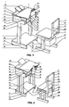
- FIG. 1 is a structural representation of a desk in accordance with example 1 of the invention.
- FIG. 2 is a structural representation of the desk in accordance with example 2 of the invention.
- FIG. 3 is a structural representation of the desk in accordance with example 3 of the invention.
- FIG. 4 is a sectional view of a moveable tube of FIG. 3 ;
- FIG. 5 is a structural representation of the desk in accordance with example 4 of the invention.
- FIG. 6 is a front view of a chair shown in FIG. 5 ;
- FIG. 7 is a side view of the chair of FIG. 6 ;
- FIG. 8 is a schematic diagram of the chair of FIG. 6 in use
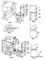
- FIG. 9 is a structural representation of the desk in accordance with example 5 of the invention.
- FIG. 10 is a schematic diagram of a connecting method of the desk and chair of FIG. 9 ;
- FIG. 11 is a schematic diagram of another connecting method of the desk and chair of FIG. 9 ;
- FIG. 12 is a structural representation of the desk in accordance with example 6 of the invention.
- FIG. 13 is a front sectional view of a lock mechanism of FIG. 12 ;
- FIG. 14 is a structural representation of the desk in accordance with example 7 of the invention.
- FIG. 15 is a structural representation of a lock of FIG. 14 ;
- FIG. 16 is another structural representation of a lock of FIG. 14 ;
- FIG. 17 is a side view of a connecting method of the desk and chair of FIG. 9 ;
- FIG. 18 is a side view of another connecting method of the desk and chair of FIG. 10 ;
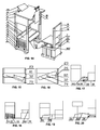
- FIG. 19 is a side view of a footrest with upper and lower plates of the invention.
- FIG. 20 is a side view of a lever type footrest of the invention.
- FIG. 21 is a layout view of a desk and chair frame of the invention.
- FIG. 22 is another layout view of the desk and chair frame of the invention.
- FIG. 23 is a third layout view of the desk and chair frame of the invention.
- FIG. 24 is a structural representation of a desk and chair in accordance with of the invention.
- FIG .25 is a structural representation of the desk and chair in accordance with example 8 of the invention.
- FIG. 26 is a front view of a desktop lifting mechanism of the invention.
- FIG. 27 is a side view of FIG. 26 ;
- FIG. 28 is a structural representation of another desktop lifting mechanism of the invention.
- FIG. 29 is a side view of FIG. 28 ;
- FIG. 30 is a side view of FIG. 28 in use
- FIG. 31 is a top view of a desk box baseplate of FIG. 28 ;
- FIG. 32 is a structural representation of a third desktop lifting mechanism of the invention.
- FIG. 33 is a top view of FIG. 32 ;
- FIG. 34 is a top view of a moveable pin of FIG. 32 ;
- FIG. 35 is a front view of FIG. 34 ;
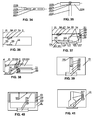
- FIG. 36 is a side sectional view of a desk backrest of the invention being mounted on the desktop which is placed horizontally;
- FIG. 37 is a side sectional view of the desk backrest and the desktop lifting mechanism of the invention being mounted on the desktop which is placed horizontally;
- FIG. 38 is a partially side sectional view of the desk backrest and the desktop lifting mechanism of the invention being mounted on a moveable connection part of the desk;
- FIG. 39 is a top view of a vertical clamp plate and a lifting plate of the desktop lifting mechanism of the invention being mounted on the desk box baseplate;
- FIG. 40 is a top view of the vertical clamp plate and the lifting plate of the desktop lifting mechanism of the invention being mounted at the left and right desk box side plates;
- FIG. 41 is a bottom view of a spring adjustment mechanism of the desktop lifting mechanism being mounted at the bottom of the desk box.
- a bionic and posture-correcting desk and chair in accordance with the invention, comprises a separate or combined desk and chair or stool, the bottom of desk legs are connected with a footrest and a chair back is connected between its supports 202, in which at the upper and lower parts of the desk and chair and/or between the desk and chair (between desk legs 8 and chair legs 8) are disposed with a posture-correcting device and a mechanism for fixing the posture-correcting device.
- the posture-correcting device allows users to maintain the correct "forward sitting position" and "backward sitting position” or the sitting position in between at all times, and meanwhile the device is replaceable at will.
- the lifting mechanism comprises a vertical slot that is disposed at the relative inner sides of the desk's left and right front legs.
- the relative inner sides of the upper ends of the left and right supports 202 are attached by a vertical plate.
- the supports 202 connecting the vertical plate and its two ends are moveable up and down the vertical slot and the inner legs.
- the upper ends of the two supports 202 are moveably connected with the front end of the desktop.
- the 1/3 of the left and right sides of the vertical plate projects upwards and passes through left and right long-strip apertures on the desktop to be parallel with the desktop.
- On the boss portion is disposed with 1-2 bookrack support holes 204.
- the moveable pin Inside the support holes is disposed with a moveable pin that fits with the recess on a support tube of the bookrack 109.
- the moveable pin has a bow-shaped leaf spring 206 or an aperture on the wall of the support hole.
- Inside the aperture is disposed with a smaller boss.
- the rear end of the boss is connected with a column, whose rear end is against a spring.
- At the rear bottom of the desktop is disposed with a position adjusting tooth 33 that fits with an edge angle 211 of the upper end of the desk box.
- the rear bottom of the desktop 3 is moveably connected with the rear upper end of the desk box.
- the rear front end of the desktop is moveably connected with the vertical plate having the same length and width as a rear plate 212 of the desk box.
- the middle portion of the left and right sides of the vertical plate projects upwards and passes through the long-strip apertures on the desktop to be parallel with the desktop.
- On the boss portion is disposed with 1-2 bookrack support holes 204. Inside the support holes is disposed with a moveable pin that fits with a support tube of the bookrack.
- At the front inner sides of the two side plates of the desk box are respectively disposed with a control groove 218 inclining backwards from top to bottom.
- the middle lower portion of the rear left and right sides of the vertical plate is moveably connected with a support pillar 219, whose lower left and right edge angles fit with the arc-shaped teeth of a desk box baseplate.
- the rear bottom of the desktop 3 is moveably connected with the rear upper end of the desk box.
- the middle portion approximately 1-2 cm from the front end of the desktop 3, is disposed with a long-strip aperture.
- Inside the aperture is provided with a moveable bracket, whose opposite left and right ends extend with a shaft and whose middle portion is connected by front and rear plates.
- the left and right sides of the moveable bracket are respectively disposed with a bookrack support hole.
- In the middle of the moveable bracket is disposed with an adjustable tube hole.
- In the middle of the bottom left and right of the inner front end of the desk box is moveably connected with an adjustable tube that is sheathed with an adjustable tubular pile.
- the upper end of the adjustable tube extends to be parallel with the desktop through the adjustable tube hole on the moveable bracket.
- the upper end of a connecting rod in the adjustable tube is connected with a button. When the button is pressed, the desktop 3 and a book placing board 115 of the bookrack 109 are always in an appropriate inclination.
- a flat square box is disposed under the chair surface or footrest.
- the contact surface between the square box and the layer cover is disposed with a long-strip aperture or pin head.
- a height-fixed desk and chair is provided with a maximum height and space 38 for high school students or tall individuals.
- a person sits on the chair 7 having the corresponding height the back is against the chair back 17, the head, chest and abdomen are against the desk backrest 21, the elbows are placed on the desktop 3, a back desktop 5, or an elbow plate 6 having the corresponding height and, and one or more footrests 20 are disposed at the place where the feet are placed.
- the footrest is directly or indirectly placed on the ground or on a track 30 or covered in a desk and chair cover to float above a connecting bracket 71.
- the desk footrest 20 has the same width as the desk and is fixed to the desk legs 8 by bolts 34 via positional adjustment holes 32.
- At left and right ends of the footrests 20 are provided with strip pads 31, which are fixed to the desk legs 8 by bolts 34 via positional adjustment holes 32.
- Between the lower portions of the chair beams 19 and chair bases 9 are connected with lower chair legs.
- the lower ends of the upper chair legs are inserted fin upper ends of the lower chair legs on the chair beam 19 and fixed by the bolts 34 via the positional adjustment holes 32.
- the desk and chair legs comprise upper legs 8 and lower legs 8 and the upper ends of the two lower legs are connected together as a whole.
- the lower ends of the two upper legs that are connected under the desk box and the chair beam 19 are respectively inserted in the upper ends of the lower legs and fixed by the bolts 34 via the positional adjustment holes 32.
- the rear ends of the chair beams 19 are moveably connected with the lower ends of the chair back supports 18.
- the opposite outer sides of the front ends of chair armrests 45 are respectively connected with an armrest plate 56.
- the armrest plate 56 is moveably connected with a moveable tube 44 outwards.
- the movable tube 44 comprises an external tube 61 and an internal tube 61.
- the front end of the internal tube 61 is moveably connected with the armrest plate 56 and the rear end of the external tube 61 is moveably connected with the chair back supports 18.
- the front end and the bottom of the external tube 61 are reversely disposed with a spring bolt 134.
- the spring bolt 134 fits with the positional adjustment holes 32 at the front lower portion of the internal tube 61.
- the rear section of the internal tube 61 is disposed with an aperture.
- the aperture moveably cooperates with an adjustable slot 94 under the rear section of the external tube 161 by the bolt 34.
- the chair back support 18 is moveable back and forth or fixed.
- the layer cover comprises a transversal layer cover 22 and a longitudinal layer cover 22.
- the width of the layer cover equals to the length between the inner sides (including the legs) of the front and rear legs of the desk or chair.
- the length of the layer cover equals to the length between the left and right legs (between the inner sides of the left and right legs).
- the layer cover is connected with the gap of one layer or multiple layers of at least two strips 23.
- the outer sides of the left and right ends of the transversal layer cover 22, or the front and rear or one end of the longitudinal layer cover 22 are separately connected with a baffle 24.
- the strips 23 are directly connected with the legs or the vertical plate 25 having the same width as the two legs.
- the left and right sides of the vertical plate 25 cover the other two sides of the legs to form a recess/square tube/circular tube layer cover, which is fixed to the legs by the bolt (spring clamp) via the positional adjustment holes 32 or moveably covered on the legs.
- a connecting plate 26 is used to connect the two ends (the bottom strips 23 or chair box side plate 16) of the vertical plate 25.
- FIGS. 9-13 on a height-fixed desk and chair is provided with a maximum height and space 38 for high school students or tall individuals.
- a person sits on the chair having the corresponding height the back is against the chair back 17, the head, chest and abdomen are against the desk backrest 21, the elbows are placed on the desktop having the corresponding height or on the elbow plate 6.
- From the lower ends (the desk bottom 10 and lower part of wheels 11) to the upper ends of the desk/chair legs 8 are connected with at least one footrest.
- the desk footrest 20 has the same width as the desk or chair and has the length equal to the space between two desk legs 8.
- the springs 35 act on the foot block 174 to leave the ground to make the desk move.
- the footrest can be placed on the ground or on a desk support plate 60 or on the connecting bracket 71 or can move in the lay cover 22.
- Under the four angles of the footrest are vertically disposed with columns 37, which are inserted in corresponding resilient support holes 32 of a footrest seat 58.
- the resilient support holes 32 are circular tubes 62 that are sheathed with springs 35 (externally or internally).
- the underside of the footrest is against by springs 35 which are sheathed higher than the circular tubes 62.
- the columns 37 of the footrest 20 whose four angles are sheathed with bolts 34 are inserted in corresponding desk/chair bases 9.
- the upper ends of the two chair bases 9 have the same size as the springs 35 and the lower ends are inserted in the apertures (big at the upper portion and small at the lower portion) having the same size as the bolts 34.
- the upper ends of the springs 35 are against the bolts 34 and the lower ends are on the platform between the upper section and the lower section.
- the footrest seat 58 is disposed on the two front chair legs.
- the two angles (above the columns 37) of the chair footrest 320 adjacent to one end of the chair are respectively disposed with an aperture and connected with a tube, which are fixed to the two front chair legs with the footrest seat 58.
- the footrest is used as the footrest seat 58 and place the spring type footrest in a rectangular square (the length and width are defined by feet) in the middle of the footrest seat 58, the footrest under pressure will be parallel with the footrest seat 58.
- the layer covers and the spring type footrest can be combined together to be disposed in the desk and chair.
- the layer covers are placed in a layer box 68, which is connected with the upper portion of the spring type footrest.
- the spring type footrest is disposed on the chair base 9, which extends 1/2 or half of the chair length.
- the front and rear bottoms of the chair base 9 are respectively disposed with wheels 11 to fit with the desk that is either fixed to the ground or disposed on the connecting bracket 71.
- the layer cover between the left and right chair legs matches with the chair and the desk is applicable to a plurality of chairs.
- the layer cover is mounted from the left and right sides of the footrest and the baffle is mounted at the rear end of the layer cover.
- the layer box 68 can be disposed on the connecting bracket 71 or the track 30. Use a hinge to connect the rear upper end of the layer box 68 to the front of the chair front legs of the connecting bracket 71.
- the front two upper ends of the layer box 68 extend to the left and right sides with a butt plate.
- the butt plate is either on the connecting bracket 71 or the track 30.
- the chair fits with the desk that is fixed on the connecting bracket 71.
- the chair is fixed at the rear of the connecting bracket 71.
- the desk whose front and rear legs are disposed with wheels 11 and desk base-tops 10 is placed on the connecting bracket 71 or the track 30.
- the relative outer lower ends of the desk legs are connected with the upper section of a flat bar 73.
- the relative inner lower ends of the lower section of the flat bar 73 are connected with the longitudinal layer cover 22 and float under the desk legs.
- the front and rear bottoms of the chair base 9 are respectively disposed with wheels 11 to fit with the desk that is fixed to the rear of the connecting bracket 71.
- the lower portions of the desk legs are moveably disposed with a transversal or longitudinal layer cover 22.
- the underside of the bottom strip 23 of the transversal layer cover 22 is connected with the upper end of the columns 37 of the spring type footrest.
- the spring type footrest uses the two desk bases 9 whose front and rear sides are disposed with wheels 11 as the footrest seat 58.
- the desk footrest 20 that fits with the transversal layer cover 22 is disposed in a moveable cover 76.
- the width of the moveable cover 76 equals to the width between the front and rear sides (including the front and rear desk legs) of the transversal layer cover 22 and the length of the moveable cover equals to the length between the left and right desk legs.
- the inward recess at the opposite sides of the left and right moveable cover 76 is formed by vertical plates, upper/lower strips and front/rear baffles.
- the front of the recess is disposed with a convex plate 78 at the left and right legs.
- the convex plate is then equipped with a spring.
- the rear of the recess is sheathed with the desk footrest 20 whose width equals to the length of the desk leg.
- the shaft passes through the aperture, the spring and the convex plate 78 that are in the recess of the desk footrest 20 to fix the desk footrest to the center of the front and rear baffles of the recess.
- the upper and lower portions of the front section of the recess are attached by the connecting plate 26 as a whole. Because the desk footrest 20 is extendable and the desk can move close to the chair, the leg cover opening 85 is not required.
- the middle of the two desk bases 9 and the connecting plate 26 in the middle of the desk bases 9 are disposed with a lock 79.
- An aperture 232 in the middle of the left and right sides of the long-strip plate 82 of the lock 79 is moveably connected with the corresponding portion of the connecting plate 26 and the aperture 232 is used as the centre of circle to the bottom of the strips 23 at the middle of the front and rear desk legs as an arc edge 81.
- the arc edge 81 at the two ends of the long-strip plate 82 moves to the front and rear inner sides of the left and right strips 23, and the lower end of the columns 37 under pressure can reach to the ground.
- the upper portion of the chair legs are further equipped with the longitudinal layer cover 22 and the flat square 182. Furthermore, it is possible to make apertures at the front and rear of the bottom strip 23 to the chair. Then use a reversed T-shaped pin to fasten from bottom to top and rotate 90 degree to place the pin on a reversed hook at the L-shaped opening under the strip 23.
- a height-fixed desk and chair is provided with a maximum height and space 38 for high school students or tall individuals.
- a person sits on the chair having the corresponding height the back is against the chair back 17, the head, chest and abdomen are against the desk backrest 21, the elbows are placed on the desktop having the corresponding height or on the elbow plate 6.
- From the lower ends (the desk bottom 10 and lower part of wheels 11) to the upper ends of the desk/chair legs 8 are connected with at least one footrest. In the 1/4 point from the lower end of the desk and chair to the maximum height is moveably connected with the chair footrest 320.
- the width of the chair footrest 320 is the width of the desk and chair and the length of the chair footrest is the maximum length when the desk and chair are separate. At that point, the footrest can be placed on the ground or on a desk support plate 60 or on the connecting bracket 71 or can move in the lay cover. The footrest and the support plate 60 can be adjusted up and down by the bolts 34 of the positional adjustment holes 32.
- the posture-correcting device and the mechanism for fixing the posture-correcting device on the height-unadjustable desk and chair is disposed with a maximum height and space 38 for high school students or high individuals.
- a person sits on the chair having the corresponding height the back is against the chair back 17, the head, chest and abdomen are against the desk backrest 21, the elbows are placed on the desktop having the corresponding height or on an elbows plate 6, and one or more footrests are disposed at the place where the feet are placed.
- the 1/4 point from the lower end of the desk and chair to the maximum height is moveably connected with the chair footrest 320.
- the width of the chair footrest 320 is the width of the desk and chair and the length of the chair footrest is the maximum length when the desk and chair are separate.
- the footrest can be placed on the ground or on a desk support plate 60 or on the connecting bracket 71 or can move in the lay cover.
- the footrest and the support plate 60 can be adjusted up and down by the bolts 34 of the positional adjustment holes 32.
- the footrest is covered in the layer cover.
- the positional adjustment holes 32 fit with each layer distance of the layer covers.
- the chair footrest 320 on the chair legs fits with the layers of the longitudinal layer cover 22 at the same level of the lower portion of the desk legs.
- the chair surface fit with the layer covers on the chair legs.
- the front and rear of the two desk bases 9 are disposed with the wheels 11.
- the footrest or the support plate 60 is disposed with the leg cover opening 85 or the leg cover hole, or under the footrest or the support plate 60 is disposed with a leg space 87.
- the width of the leg cover opening 85 of the desk footrest 20 close to the chair is a little more than the width of the left and right chair front legs or equal to the width between the left and right front legs or the chair box 12.
- the front and rear of the desk come close to the maximum of one or two vertical rectangle or a transversal rectangular opening.
- the leg cover opening 85 fits with the leg cover hole.
- the leg cover hole which is at the front (or slightly at the rear side) of the desk footrest 20 fits with the leg cover opening 85 at the rear of the desk footrest.
- the width of the leg cover hole equals to the width of the leg cover opening 85 and the length is slightly longer than the length between the front and rear of the front leg.
- the shape is one or two square, rectangle or circle or a transversal rectangular hole or opening.
- the leg space 87 is at the bottom of the desk footrest 20.
- the height of the leg space is slightly higher than or as high as the chair base 9 and the width is slightly wider than the chair base 9 or comprises the two chair bases 9.
- the length of the leg space is in the space of two vertical cuboids or a big transversal flat cuboid of the desk footrest 20 when the chair base 9 is sheathed into the desk footrest 20 to the limit.
- the leg cover opening 85 and the leg cover hole on the support plate 60 or the leg space 87 under the support plate are similar to the desk footrest 20.
- the footrest in order for the feet to be placed on the footrest, the footrest is required to be wider. If the chair has single left and right legs, the footrest 20 is required to have the leg space 87 to be covered in the chair base 9. As shown in FIG. 31 , in order for the desk and chair legs to be sheathed together, the desk footrest 20 is disposed with left and right leg cover openings 85.
- the desk 1 is disposed with the desk backrest 21.
- the desk backrest 21 comprises a bracket body at the rear of the desk where a mounting bracket 90 is disposed.
- the mounting bracket 90 is on the desk or on the base plate 91 at the upper end of the desk box.
- An upper adjustable plate 98 is inserted into a traversal slot 67 on the desktop or the base plate 91, which is disposed at the bottom of the desktop 3 or above or under the base plate 91.
- the desktop 3 or the base plate 91 can be used as a slot plate 96 or upper plate 97.
- the lower rear end of the desktop 3 is moveably connected with the rear upper end of the desk.
- the desk having the desk backrest 21 is disposed with the desktop lifting mechanism.
- the desktop lifting mechanism is placed in the middle of the desk box baseplate 13 and the two sides of the desktop lifting mechanism are fixed with vertical clamp plate 101.
- the vertical clamp plates are used to clamp a pumpkin-seed-shaped lifting plate 102 of the desk box baseplate 13.
- the desk box side plates 16 whose left and right lifting plates 102 are disposed at the inner sides of the desk box and which are used as the vertical clamp plate 101 are clamped by the relative inner sides of the vertical clamp plate 101.
- the rear upper portion of the vertical clamp plate 101 is moveably connected with the corresponding part of the lifting plate 102.
- the rear top end of the lifting plate 102 is moveably connected with the front end (with the holes 32 and bolts 34) of a secondary connecting plate 103.
- the rear of the secondary connecting plate 103 is placed on a raised edge 104 at the rear edge of the adjustable baseplate 89 and the raised edge extends out of the adjustable baseplate.
- the lower adjustable plate 99 that is moveably connected with the lower end (slightly at the upper position) of the sternal/ventral plate 178 is moveably connected with a step 105 and a flat plate 106 on the secondary connecting plate 103 as well as a magnet 57 that is disposed in the middle of the raised edge 104 of the adjustable baseplate 89.
- the front ends of the left and right lifting plates 102 are connected with 1-2 connecting plate 26.
- the bottom of the desk box baseplate 13 is reversely disposed with a spring adjustment element.
- a reversed hanger plate 107 of the spring adjustment element is in the middle of the left and right front ends.
- the reversed hanger plate is moveably connected with the front end of a longitudinal plate 261 and 1-2 columns 83 stand on the rear front end or slightly inner position of the reversed hanger plate.
- the spring 35 on the column 83 supports the desk box baseplate 13 and is against the longitudinal plate 261.
- the column 83 passes through the hole 32 on the desk box baseplate 13.
- the upper end of the column is sheathed with a hanger plate whose diameter is larger than that of the column 83 and is moveably hanged on the desk box baseplate 13 to be parallel with the upper portion of the adjustable baseplate 89.
- the longitudinal plate 261 is placed on the reversed hook at the bottom of the column.
- the secondary connecting plate 103 is disposed with an aperture to fit with the column 83.
- the upper arc of the lifting plate 102 is moveably connected with the magnet that is disposed at the bottom of the desktop.
- the desk 1 equipped with the desktop lifting mechanism is moveably connected with a bookrack 109.
- a bookrack seat 110 at the front end of the lifting plate 102 is moveably connected with 1-2 frame tubes 111 in the transversal direction.
- the upper end of the frame tube 111 vertically passes through and extends over the top of the desktop.
- the bookrack 109 is composed of the book placing board 115 and 1-2 support tubes 112 that are moveably connected at the rear of the bookrack.
- the book placing board 115 is disposed with a book holding groove 116 and the lower end of the book placing board is connected with a book baffle.
- the support tube 112 of the bookrack 109 and the frame tube 111 are moveably sheathed together.
- the frame tube 111 on the desktop is sheathed with a moveable pad or the lower end of the support tube 112 is connected with a circular pad.
- the arc-shaped angle at the lower end of the book placing board 115 attracts with the forward and backward magnets on the desktop.
- the bookrack 109 can be flat or inclined along with the desktop lifting mechanism and the book placing board 115 always remains the optimal distance and angle with eyes.
- the left and right sides of the book placing board 115 indirectly attracts with the opened book by magnet.
- the frame tube 111 can be taken out from the desktop and inclinedly against a bracket or the connecting plate 26 of the desk box front plate 15.
- the other end of the upper moveable connecting mechanism is moveably connected with the lower end of the frame tube 111 in the transversal direction and is rotatable back and forth.
- the frame tube 111 can vertically extends over the top of the desktop.
- the book placing board 115 and the support tube 112 are disposed with a clamp and a storage slot.
- the desktop is disposed with the desktop lifting mechanism, which is at the upper and lower sides in the transversal direction of the length of a lifting adjustment plate 126.
- One side is parallel and the other side is inclined.
- the adjustable slot 94 is parallel with the parallel edge of the lifting adjustment plate 126.
- the lifting adjustment plate 126 is fixed on the desk box side plate 16 by bolts 34 via the adjustable slot 94.
- the adjustable slot 94 parallel to the lifting adjustment plate 126 can be transversally disposed at the corresponding position of the desk box side plate 16. In the middle of the transversal adjustable slot 94 is disposed with a vertical slot.
- the lifting adjustment plate 126 is sheathed on the desk box side plate 16 by bolts 34 via the adjustable slot 94.
- the chair 2 is on the ground.
- the front of the desk is disposed with the wheel 11 and the rear of the desk is disposed with the desk base-top 10.
- the front and rear of the desk are both disposed with the wheels 11, or the desk is fixed on the ground, or the front and rear of the chair are both disposed with the wheels 11.
- the chair is fixed on the ground at the inner side of the two parallel tracks 30 or close to the inner side of the two tracks 30 or on the tracks 30.
- the desk is on the two tracks 30 or close to the outer side of the tracks 30 or on the ground at the outer side of the tracks 30.
- the front of the desk is disposed with the wheel 11 and the rear of the desk is disposed with the desk base-top 10, or the front and rear of the desk are both disposed with the wheels 11, or the desk is fixed on the ground at the outer side of the two parallel tracks 30 or close to the outer side of the tracks 30 or on the tracks 30.
- the chair is on the two tracks 30 or close to the inner side of the track 30 or on the ground at the inner side of the track 30.
- the chair is disposed on the track 30 of a desk/chair holder 130 or of a double-layer desk/chair holder 131 or disposed on the connecting plate 26.
- the desk is disposed on the track 30 at the front of the chair, the front of the desk is disposed with the wheel 11, and the rear of the desk is disposed with the desk base-top 10 or both the front and rear of the desk are disposed with the wheels 11.
- the desk is disposed on the track 30 of the desk/chair holder 130 or of the double-layer desk/chair holder 131 or disposed on the connecting plate 26.
- the chair is disposed on the track 30 at the rear of the desk and both the front and rear of the chair are disposed with the wheels 11.
- the desk/chair holder 130 is a frame composed of one or more pairs of longitudinal tracks 30 and two or more transversal connecting plates 26, or the double-layer desk/chair holder 131 is formed by connecting the upper and lower frames.
- the desk/chair holder 130 and the double-layer desk/chair holder 131 are disposed with support legs 136 or the wheels 11.
- the desk/chair holder 130 and the double-layer desk/chair holder 131 can be disposed with one or more sets or one or more rows of desks and chairs in the longitudinal and transversal directions, respectively. The desks and chairs are not against one another.
- the longitudinal layer cover 22 and the chair 2 are moveable back and forth along the track 30, which turn upwards to lean against the desk/chair holder 130, or the front end of the desk/chair holder 130, or the connecting plate 26.
- the lower sections of the chair legs 8 can be omitted. It is only required to mount the upper sections of the chair legs on the desk/chair holder 130, or the inner sides of the tracks 30 and the connecting plate 26.
- One end of the desk/chair holder 130 of the bionic and posture-correcting desk and chair is disposed with a frame head 141, or the driver seat is combined with the chair 2 as a whole.
- the chair back 17 is moveably connected with the desk backrest 21 in an indirect way.
- the chair back 17 is moveably connected with the upper section of the chair back support 18 by bolts 34 via the positional adjustment holes 32 on the chair back support 18.
- the chair back 17 is disposed with a willow backrest 135.
- the pillow backrest 135 is covered by a pillow 137 and provides support 176 for the waist.
- the lower end of the pillow backrest 135 can be inserted in the chair back support 18 or a storage tube 138 at the rear of the chair legs.
- the chair box 12 comprises a cover plate, a bottom plate, left and right side plates 16, a rear block plate 74, and chair box door 140.
- the user When the desktop is flat, the user is “clamped” in the middle of the desk backrest 21 and the chair back 17 to maintain the correct "forward sitting position” and “backward sitting position” or the sitting position in between at all times, and meanwhile the sitting positions can be easily adjusted or changed.
- the book placing board 115 can be pulled or pushed forwards or backwards and is moveable up and down the frame tube 111 together with the support tube 112. The book placing board 115 maintain the optimal distance and angle with eyes.
- the lower adjustable plate 99 is moveable along the step 105 of the secondary connecting plate 103. When the desk backrest 21 leans forwards to the maximum limit of the correct "forward sitting position", the lower adjustable plate 99 will fall from the step 105 to the flat plate 106 underneath.
- the end of the lower adjustable plate 99 will be against the front of the secondary connecting plate 103 at the front of the flat plate 106. At this point, it is the fixed and correct "forward sitting position". If the user uses the study position with the inclined desktop, when the user uses his elbows to press the elbow plate 6 and uses his abdomen to act on the sternal/ventral plate 178, the secondary connecting plate 103 will move forwards under the effect of the adjustable baseplate 89. The end of the secondary connecting plate 103 will be naturally placed in the inner side of the raised edge 104 of the adjustable baseplate 89 and against with each other. The front end of the lifting plate 102 will be gradually raised up and stop after it pushes the desktop to get the required inclined state.
- the support tube 112 is moveably connected with the frame tube 111 and goes up with front end of the lifting plate 102.
- the lower end of the book placing board 115 moves forwards on the desktop and remains the optimal distance and angle with eyes.
- the front end of the lower adjustable plate 99 is moveable along the flat plate 106 and the raised edge 104. At this point, the user can lean forwards or backwards with the desk backrest 21 and the chair back 17, and maintain the correct "forward sitting position” and "backward sitting position” or the sitting position in between at all times, and meanwhile the sitting positions which are comfortable and unlikely to cause fatigue can be easily adjusted or changed.
- the user can use his elbows to press the elbow plate 6 and uses his abdomen to push the sternal/ventral plate 178 to maintain balance.
- the desktop can be easily made with different inclined angles for correct "backward sitting position". If the user intends to use the study position with the flat desktop again, he can use his elbows to press the elbow plate 6 and use his abdomen to act on the sternal/ventral plate 178, and at the same time use one feet that is on the desk footrest 20 to kick the rear of the lower longitudinal plate 261 to enable the column 83 to push the secondary connecting plate 103 to the top of the raised edge 104 of the adjustable baseplate 89.
- the users uses his elbows to press the elbow plate 6 to allow the desktop to slowly drop, he uses the chest to act on the sternal/ventral plate 178 of the desk backrest 21 to allow the desk backrest 21 to be back to the position for correct "forward sitting position".
- the desktop will be back to the flat position.
- the support tube 112 is sheathed with the frame tube 111 and perpendicularly drops with the desktop.
- the lower end of the book placing board 115 moves backwards and remains the optimal distance and angle with eyes.
- the user intends to lean forwards or backwards, he can use his feet to kick the rear of the longitudinal plate 261 to allow the column 83 to pass through the aperture on the secondary connecting plate 103 and push the lower adjustable plate 99 from the flat plate 106 to the step 105 of the secondary connecting plate 103 under the condition that the end of the lower adjustable plate 99 is moveable on the step 105 of the secondary connecting plate 103.
- the user will always be at the correct "forward sitting position” or “backward sitting position” or any position in between, and meanwhile the sitting positions can be changed at will. If the user intends to change the distance between the desk and the chair or have a rest, what he needs to do is to raise his feet and push or pull the desk or chair once.
- the chair back support adjustment mechanism divides the left and right chair back supports 18 into upper and lower chair back supports.
- the upper chair back support is covered in the lower chair back support.
- the relative inner sides of the upper ends of the two upper chair back supports are moveably connected with the chair back 17.
- the lower sections of the two upper chair back supports are fixed with a resilient adjustment pin.
- the resilient adjustment pin is a resilient strip (piece) and is in a bended shape (or the circular bended shape).
- the end of the bended strip is disposed with 1-2 projected pins, passing through the aperture on the inner wall of the upper chair back support and fit with the positional adjustment holes of the lower chair back support.
- the two ends of the chair back 17 are moveably connected with the upper chair back support and can be adjusted up and down in the lower chair back support.
- a user sits on the chair, he withdraws his feet, uses his hands to pull or push the desk or chair to the appropriate distance, allows his waist to lean against the chair back 17 and chest/abdomen lean against the sternal/ventral plate 178, uses his feet to stamp on the footrest hardly to allow the desk to be securely connected with the chair as a whole.
- the desk backrest 21 will move with the chair back 17 and the user will be "clamped" in the middle.
- the book placing board 115 is adjustable back and forth to maintain the optimal distance and angle with eyes.
- the lower adjustable plate 99 is on the adjustable baseplate 89 to move back and forth.
- the chin is on the chin pad and the neck becomes shorter.
- the neck become longer. Consequently, the user is required to press the adjustment button on the desk backrest 21 when to change the sitting position. In that case, the adjustable support can be extended and the chin can be placed on the chin pad.
- the middle portion of the desk footrest 20 is disposed with a foot button 235.
- the lower portion of the foot button 235 is connected with a foot block 174 by the springs 35.
- the springs 35 act on the foot block 174 to leave the ground to make the desk move.
- the springs 35 act on the foot block 174 to be tightly against the ground because feet are placed on foot button 235.
- the above structure can also be used for chair footrest 320.
- the desk backrest 21 used in the invention can also be replaced by the bionic and posture-correcting backrest for study described in the patent 2009201681014.
Applications Claiming Priority (2)
| Application Number | Priority Date | Filing Date | Title |
|---|---|---|---|
| CN200920166775 | 2009-08-12 | ||
| PCT/CN2010/075952 WO2011018046A1 (fr) | 2009-08-12 | 2010-08-12 | Table et chaise pour corrections bioniques de posture |
Publications (3)
| Publication Number | Publication Date |
|---|---|
| EP2465376A1 true EP2465376A1 (fr) | 2012-06-20 |
| EP2465376A4 EP2465376A4 (fr) | 2012-06-20 |
| EP2465376B1 EP2465376B1 (fr) | 2013-05-15 |
Family
ID=43585973
Family Applications (1)
| Application Number | Title | Priority Date | Filing Date |
|---|---|---|---|
| EP10807991.4A Not-in-force EP2465376B1 (fr) | 2009-08-12 | 2010-08-12 | Table et chaise pour corrections bioniques de posture |
Country Status (7)
| Country | Link |
|---|---|
| US (1) | US20120187727A1 (fr) |
| EP (1) | EP2465376B1 (fr) |
| JP (1) | JP2013501545A (fr) |
| KR (1) | KR101513114B1 (fr) |
| CN (1) | CN102143698B (fr) |
| HK (1) | HK1160365A1 (fr) |
| WO (1) | WO2011018046A1 (fr) |
Cited By (3)
| Publication number | Priority date | Publication date | Assignee | Title |
|---|---|---|---|---|
| CN103263170A (zh) * | 2013-05-23 | 2013-08-28 | 莫经刚 | 移动升降式手术观摩凳 |
| CN103892581A (zh) * | 2014-04-15 | 2014-07-02 | 张树香 | 一种带防近视装置的桌子 |
| CN105433595A (zh) * | 2015-11-30 | 2016-03-30 | 苏州迪诺环保科技有限公司 | 一种多功能电脑桌 |
Families Citing this family (55)
| Publication number | Priority date | Publication date | Assignee | Title |
|---|---|---|---|---|
| USD743189S1 (en) | 2013-03-15 | 2015-11-17 | Herman Miller, Inc. | Workstation |
| CN203505989U (zh) * | 2013-09-03 | 2014-04-02 | 谢立艺 | 学生多功能防近视器 |
| CN103445493A (zh) * | 2013-09-10 | 2013-12-18 | 昆山市巴城镇顺拓工程机械配件厂 | 一种多功能电脑桌 |
| CN103584935A (zh) * | 2013-10-29 | 2014-02-19 | 李明科 | 一种坐姿矫正器 |
| US8919264B1 (en) * | 2014-04-08 | 2014-12-30 | WL Innovations, LLC | Work surface height adjustor with universal mount |
| CN104490099A (zh) * | 2014-12-26 | 2015-04-08 | 融水苗族自治县教育局 | 可调学生课桌椅 |
| ES2582359B1 (es) * | 2015-03-10 | 2017-07-17 | Universidad De Murcia | Mesa de reproducción digital de documentos |
| CN104706012B (zh) * | 2015-03-27 | 2017-06-06 | 西安文理学院 | 一种防近视无纸化通讯互动课桌辅助设备及通讯方法 |
| KR200478375Y1 (ko) | 2015-07-30 | 2015-09-24 | 고영기 | 궁도 심판용 테이블 |
| CN105815936A (zh) * | 2016-05-11 | 2016-08-03 | 常州市诚天电子有限公司 | 办公桌配套移动桌 |
| CN105919326A (zh) * | 2016-06-29 | 2016-09-07 | 赵小舞 | 一种用于休闲娱乐自动移动临时休息装置 |
| CN105996438A (zh) * | 2016-07-26 | 2016-10-12 | 胡忠梁 | 一种一体式折叠桌椅 |
| CN106343786B (zh) * | 2016-09-08 | 2018-07-27 | 王益 | 易拆卸支撑式学生课桌桌脚 |
| CN106263521A (zh) * | 2016-10-12 | 2017-01-04 | 湖南想信息科技有限公司 | 一种可加热的带脚板餐桌 |
| CN106360963A (zh) * | 2016-10-12 | 2017-02-01 | 湖南想信息科技有限公司 | 一种具有脚底按摩功能的餐桌 |
| CN106388252A (zh) * | 2016-10-12 | 2017-02-15 | 湖南想信息科技有限公司 | 一种多功能餐桌 |
| CN106490838A (zh) * | 2016-12-23 | 2017-03-15 | 安徽师范大学 | 多功能读书器 |
| CN106724046A (zh) * | 2017-01-18 | 2017-05-31 | 河南嘉宇医疗科技有限责任公司 | 一种多功能坐姿矫正学习桌 |
| CN106820613B (zh) * | 2017-02-27 | 2022-09-02 | 新乡学院 | 一种新型课桌 |
| CN109090840A (zh) * | 2017-06-20 | 2018-12-28 | 代连水 | 学习桌 |
| CN107744262A (zh) * | 2017-11-30 | 2018-03-02 | 陈奕明 | 坐姿矫正器及具有坐姿矫正器的课桌 |
| CN108175220A (zh) * | 2018-01-18 | 2018-06-19 | 陈磊 | 一种新型多功能婴幼儿餐桌 |
| CN108158224B (zh) * | 2018-02-07 | 2023-10-03 | 杨益民 | 滑动式贮物容器设置限位和脱卸的学生椅凳 |
| CN108185662A (zh) * | 2018-03-01 | 2018-06-22 | 戴震东 | 一种多功能组合式保健课桌 |
| CN108402656A (zh) * | 2018-05-11 | 2018-08-17 | 钦州市小海星青少年科学普及中心 | 可折叠书桌 |
| CN108771347A (zh) * | 2018-06-08 | 2018-11-09 | 潘家桢 | 一种可调节温度的舒适学生课桌 |
| CN109083813B (zh) * | 2018-06-19 | 2021-03-30 | 佳木斯大学 | 一种风力发电机座调节装置及操作方法 |
| CN108814068A (zh) * | 2018-06-25 | 2018-11-16 | 袁天泽 | 一种便于移动的多功能学生用座椅 |
| EP3841922A4 (fr) * | 2018-08-22 | 2022-06-01 | Gwak, Taeyeong | Appareil de correction de position |
| CN111012056A (zh) * | 2018-10-09 | 2020-04-17 | 舒柯萌 | 一种防作弊课桌 |
| CN109393733B (zh) * | 2018-12-20 | 2021-02-23 | 佛山市宝格玛家具有限公司 | 一种多功能按摩电脑桌装置 |
| RU192593U1 (ru) * | 2019-04-03 | 2019-09-23 | Павел Валентинович Бажанов | Стул для сексуальных контактов |
| CN111053369A (zh) * | 2019-12-30 | 2020-04-24 | 广州创显科教设备有限公司 | 一种支持书写护眼的设备 |
| CN111134445A (zh) * | 2020-01-10 | 2020-05-12 | 欧阳俊祺 | 一种便于休息的办公桌 |
| CN111870043A (zh) * | 2020-08-13 | 2020-11-03 | 徐海涛 | 一种具有防止眼睛近视功能的课桌 |
| CN111772346A (zh) * | 2020-08-13 | 2020-10-16 | 徐海涛 | 一种能防止眼睛近视的课桌 |
| CN111972845B (zh) * | 2020-08-31 | 2022-12-13 | 云阳县栖霞镇栖霞小学 | 一种可预防学生驼背课桌椅 |
| CN111972846B (zh) * | 2020-08-31 | 2022-12-16 | 广东乔帝智能家居制造有限公司 | 一种可移动多功能储存课桌椅 |
| CN112568597A (zh) * | 2020-11-06 | 2021-03-30 | 泉州智绿康智能设备有限公司 | 一种智能化儿童学习与训练的功能桌 |
| CN112401492B (zh) * | 2020-11-18 | 2022-12-09 | 广东帝邦家具有限公司 | 一种高度与角度可调节的学生课桌 |
| CN112568616B (zh) * | 2020-12-15 | 2023-06-23 | 广东华盛家具集团有限公司 | 一种方便腾出空间的课桌 |
| CN112603048B (zh) * | 2020-12-15 | 2024-02-13 | 江苏中淘家居科技有限公司 | 一种基于人体工程学的矫正课桌 |
| CN112586892B (zh) * | 2020-12-17 | 2022-12-06 | 云阳县紫金小学 | 一种靠背可调节防驼背学生课桌 |
| CN112932067B (zh) * | 2021-02-07 | 2022-12-06 | 云阳县沙市镇沙市小学 | 一种智能拉伸教学讲台 |
| CN113053211A (zh) * | 2021-03-16 | 2021-06-29 | 福州外语外贸学院 | 一种英语教学专用教学板 |
| CN112998699B (zh) * | 2021-04-02 | 2022-12-13 | 四川写正智能科技有限公司 | 一种用于检测用户运动状态的雷达传感器系统及检测方法 |
| CN113040527B (zh) * | 2021-05-07 | 2022-05-17 | 江西省南城县发华实业有限公司 | 一种具有防驼背功能课椅 |
| CN113349573A (zh) * | 2021-06-22 | 2021-09-07 | 彭嵩 | 一种智能升降办公桌椅及其调控方法 |
| CN113712377B (zh) * | 2021-07-19 | 2022-08-26 | 浙江科沃传动机械有限公司 | 一种升降桌及一体式桌椅装置及群体坐姿干预方法 |
| US20230172364A1 (en) * | 2021-12-08 | 2023-06-08 | Lars Per Bildman | Systems and methods for a standing chair for use with a standing desk |
| CN114403594A (zh) * | 2022-01-26 | 2022-04-29 | 黄士喜 | 一种矫正姿势的课桌 |
| CN115005600B (zh) * | 2022-04-14 | 2023-06-16 | 河南工业职业技术学院 | 一种教学的管理系统 |
| CN114916774B (zh) * | 2022-06-16 | 2023-11-03 | 天津市疾病预防控制中心 | 一种预防小学生近视和脊柱弯曲用的座椅 |
| CN115067667A (zh) * | 2022-06-23 | 2022-09-20 | 燕山大学 | 一种高低可调式移动自锁桌子 |
| CN115474763B (zh) * | 2022-09-06 | 2023-07-14 | 湖北师范大学 | 一种多功能讲台 |
Citations (4)
| Publication number | Priority date | Publication date | Assignee | Title |
|---|---|---|---|---|
| DE10977C (de) * | 1900-01-01 | R. BITHORN in Berlin W., Französischeste 14 | Verstellbares Schreibpult | |
| FR683719A (fr) * | 1928-10-25 | 1930-06-17 | Banc d'école réglable | |
| US5174223A (en) * | 1989-09-20 | 1992-12-29 | Nagy Marta K | Ergonomically designed computer workstation adjustable to various sitting and standing positions |
| FR2845877A1 (fr) * | 2002-10-16 | 2004-04-23 | Andy Mat | Support d'assise pliable |
Family Cites Families (21)
| Publication number | Priority date | Publication date | Assignee | Title |
|---|---|---|---|---|
| US4128317A (en) * | 1977-06-01 | 1978-12-05 | Lecover Maurice | Positioning means for ophthalmic examinations |
| JPS58164536U (ja) * | 1982-04-26 | 1983-11-01 | 株式会社一ノ坪製作所 | 書架台 |
| CN2030822U (zh) * | 1987-06-11 | 1989-01-18 | 单正忠 | 调节式多功能课桌椅 |
| US4798411A (en) * | 1987-07-08 | 1989-01-17 | Lin Pao C | Collapsible combined table and chair assembly |
| JPH074102U (ja) * | 1993-06-16 | 1995-01-20 | 株式会社サンテック | キャスター付脚台の固定装置 |
| US5474356A (en) * | 1994-04-25 | 1995-12-12 | Johnson; Patrick A. | Book reading chairs |
| JP3010376U (ja) * | 1994-06-14 | 1995-05-02 | 幸治 鬼池 | 姿勢矯正器具 |
| SE514709C2 (sv) * | 1995-10-13 | 2001-04-02 | Nils Dencker | Arbetsbänk samt grupp av dylka arbetsbänkar |
| CN2274445Y (zh) * | 1996-12-31 | 1998-02-18 | 杨树金 | 学生桌椅 |
| CN1159309A (zh) * | 1997-02-03 | 1997-09-17 | 张凤林 | 学习用桌椅 |
| CN2423794Y (zh) * | 2000-05-11 | 2001-03-21 | 火惠卿 | 学习姿势校正架 |
| JP4139886B2 (ja) * | 2002-08-30 | 2008-08-27 | 独立行政法人国立高等専門学校機構 | 身体保持装置付き椅子机 |
| CN2627911Y (zh) * | 2003-03-11 | 2004-07-28 | 肖琦 | 一种学习桌 |
| US7106014B1 (en) * | 2003-04-07 | 2006-09-12 | Krueger International, Inc. | Lectern |
| JP2005237529A (ja) * | 2004-02-25 | 2005-09-08 | Kintaro Co Ltd | テーブル |
| CA2523067C (fr) * | 2004-10-12 | 2013-03-12 | Altimate Medical, Inc. | Orthopodium modulaire |
| WO2008074141A1 (fr) * | 2006-12-18 | 2008-06-26 | Arnold Zidulka | Chaise polyvalente |
| CN101449881A (zh) * | 2007-11-30 | 2009-06-10 | 上海市静安区青少年活动中心 | 一种课桌系统 |
| US7922249B2 (en) * | 2008-09-17 | 2011-04-12 | Rafael Tal Marchand | Adjustable workstation |
| KR20080100316A (ko) * | 2008-10-24 | 2008-11-17 | 양영근 | 높낮이 조절 및 발판이 구비된 학교책상 |
| US8573688B2 (en) * | 2010-01-25 | 2013-11-05 | Jon E. Shackelford | Reconfigurable seating device with integral document shelf |
-
2010
- 2010-08-12 CN CN201080002792.6A patent/CN102143698B/zh active Active
- 2010-08-12 WO PCT/CN2010/075952 patent/WO2011018046A1/fr active Application Filing
- 2010-08-12 KR KR1020127006398A patent/KR101513114B1/ko active IP Right Grant
- 2010-08-12 EP EP10807991.4A patent/EP2465376B1/fr not_active Not-in-force
- 2010-08-12 JP JP2012524100A patent/JP2013501545A/ja active Pending
-
2012
- 2012-02-03 HK HK12101049.5A patent/HK1160365A1/xx not_active IP Right Cessation
- 2012-02-13 US US13/371,489 patent/US20120187727A1/en not_active Abandoned
Patent Citations (4)
| Publication number | Priority date | Publication date | Assignee | Title |
|---|---|---|---|---|
| DE10977C (de) * | 1900-01-01 | R. BITHORN in Berlin W., Französischeste 14 | Verstellbares Schreibpult | |
| FR683719A (fr) * | 1928-10-25 | 1930-06-17 | Banc d'école réglable | |
| US5174223A (en) * | 1989-09-20 | 1992-12-29 | Nagy Marta K | Ergonomically designed computer workstation adjustable to various sitting and standing positions |
| FR2845877A1 (fr) * | 2002-10-16 | 2004-04-23 | Andy Mat | Support d'assise pliable |
Non-Patent Citations (1)
| Title |
|---|
| See also references of WO2011018046A1 * |
Cited By (4)
| Publication number | Priority date | Publication date | Assignee | Title |
|---|---|---|---|---|
| CN103263170A (zh) * | 2013-05-23 | 2013-08-28 | 莫经刚 | 移动升降式手术观摩凳 |
| CN103263170B (zh) * | 2013-05-23 | 2016-06-29 | 莫经刚 | 移动升降式手术观摩凳 |
| CN103892581A (zh) * | 2014-04-15 | 2014-07-02 | 张树香 | 一种带防近视装置的桌子 |
| CN105433595A (zh) * | 2015-11-30 | 2016-03-30 | 苏州迪诺环保科技有限公司 | 一种多功能电脑桌 |
Also Published As
| Publication number | Publication date |
|---|---|
| HK1160365A1 (en) | 2012-08-17 |
| US20120187727A1 (en) | 2012-07-26 |
| EP2465376A4 (fr) | 2012-06-20 |
| JP2013501545A (ja) | 2013-01-17 |
| EP2465376B1 (fr) | 2013-05-15 |
| KR101513114B1 (ko) | 2015-04-17 |
| CN102143698B (zh) | 2014-07-09 |
| CN102143698A (zh) | 2011-08-03 |
| KR20120089646A (ko) | 2012-08-13 |
| WO2011018046A1 (fr) | 2011-02-17 |
Similar Documents
| Publication | Publication Date | Title |
|---|---|---|
| EP2465376B1 (fr) | Table et chaise pour corrections bioniques de posture | |
| CA2596533C (fr) | Siege de support ajustable pour jambes croisees | |
| EP2204153B1 (fr) | Chaise de tatouage | |
| JP2013501545A5 (ja) | 人間工学に基づいた姿勢を矯正するためのイス・デスク | |
| US9585478B1 (en) | Adjustable seating | |
| EP2465378A1 (fr) | Cadre correcteur de posture bionique sur lequel s'appuyer pendant des cours | |
| CA2734571C (fr) | Chaise a siege inclinable | |
| US9913541B2 (en) | Adjustable seating assembly | |
| CN201123536Y (zh) | 预防近视驼背脊柱侧弯学生专用桌椅 | |
| US7261368B1 (en) | Ergonomic chair | |
| CN100502728C (zh) | 一种矫姿保健坐椅 | |
| CN200994588Y (zh) | 一种矫姿保健坐椅 | |
| CN104433277B (zh) | 多功能教室用课桌椅 | |
| WO2021213246A1 (fr) | Chaise multifonctionnelle permettant de s'allonger sur le ventre et de s'asseoir | |
| KR20090041458A (ko) | 척추교정용 가구 | |
| CN220494635U (zh) | 一种办公椅 | |
| RU89932U1 (ru) | Комплект мебели | |
| KR20040006620A (ko) | 사용이 편리한 일체형 책걸상 | |
| GB2530580A (en) | Sunlounger | |
| KR200295304Y1 (ko) | 사용이 편리한 일체형 책걸상 | |
| JP3109359U (ja) | 背筋伸ばし健康器具 | |
| UA145367U (uk) | Стілець-трансформер | |
| RU66914U1 (ru) | Комплект мебели для работы или учебы | |
| CN113040542A (zh) | 用课桌椅实现午睡功能的方法及午睡课桌椅 | |
| Congleton | Office Ergonomics: Why do people hurt? What can you do about it? |
Legal Events
| Date | Code | Title | Description |
|---|---|---|---|
| PUAI | Public reference made under article 153(3) epc to a published international application that has entered the european phase |
Free format text: ORIGINAL CODE: 0009012 |
|
| 17P | Request for examination filed |
Effective date: 20120312 |
|
| A4 | Supplementary search report drawn up and despatched |
Effective date: 20120522 |
|
| AK | Designated contracting states |
Kind code of ref document: A1 Designated state(s): AL AT BE BG CH CY CZ DE DK EE ES FI FR GB GR HR HU IE IS IT LI LT LU LV MC MK MT NL NO PL PT RO SE SI SK SM TR |
|
| 17Q | First examination report despatched |
Effective date: 20120612 |
|
| DAX | Request for extension of the european patent (deleted) | ||
| GRAP | Despatch of communication of intention to grant a patent |
Free format text: ORIGINAL CODE: EPIDOSNIGR1 |
|
| GRAS | Grant fee paid |
Free format text: ORIGINAL CODE: EPIDOSNIGR3 |
|
| GRAA | (expected) grant |
Free format text: ORIGINAL CODE: 0009210 |
|
| AK | Designated contracting states |
Kind code of ref document: B1 Designated state(s): AL AT BE BG CH CY CZ DE DK EE ES FI FR GB GR HR HU IE IS IT LI LT LU LV MC MK MT NL NO PL PT RO SE SI SK SM TR |
|
| REG | Reference to a national code |
Ref country code: CH Ref legal event code: EP Ref country code: GB Ref legal event code: FG4D |
|
| REG | Reference to a national code |
Ref country code: AT Ref legal event code: REF Ref document number: 611662 Country of ref document: AT Kind code of ref document: T Effective date: 20130615 |
|
| REG | Reference to a national code |
Ref country code: IE Ref legal event code: FG4D |
|
| REG | Reference to a national code |
Ref country code: DE Ref legal event code: R096 Ref document number: 602010007176 Country of ref document: DE Effective date: 20130711 |
|
| REG | Reference to a national code |
Ref country code: AT Ref legal event code: MK05 Ref document number: 611662 Country of ref document: AT Kind code of ref document: T Effective date: 20130515 |
|
| REG | Reference to a national code |
Ref country code: LT Ref legal event code: MG4D |
|
| REG | Reference to a national code |
Ref country code: NL Ref legal event code: VDEP Effective date: 20130515 |
|
| PG25 | Lapsed in a contracting state [announced via postgrant information from national office to epo] |
Ref country code: FI Free format text: LAPSE BECAUSE OF FAILURE TO SUBMIT A TRANSLATION OF THE DESCRIPTION OR TO PAY THE FEE WITHIN THE PRESCRIBED TIME-LIMIT Effective date: 20130515 Ref country code: LT Free format text: LAPSE BECAUSE OF FAILURE TO SUBMIT A TRANSLATION OF THE DESCRIPTION OR TO PAY THE FEE WITHIN THE PRESCRIBED TIME-LIMIT Effective date: 20130515 Ref country code: PT Free format text: LAPSE BECAUSE OF FAILURE TO SUBMIT A TRANSLATION OF THE DESCRIPTION OR TO PAY THE FEE WITHIN THE PRESCRIBED TIME-LIMIT Effective date: 20130916 Ref country code: ES Free format text: LAPSE BECAUSE OF FAILURE TO SUBMIT A TRANSLATION OF THE DESCRIPTION OR TO PAY THE FEE WITHIN THE PRESCRIBED TIME-LIMIT Effective date: 20130826 Ref country code: AT Free format text: LAPSE BECAUSE OF FAILURE TO SUBMIT A TRANSLATION OF THE DESCRIPTION OR TO PAY THE FEE WITHIN THE PRESCRIBED TIME-LIMIT Effective date: 20130515 Ref country code: SE Free format text: LAPSE BECAUSE OF FAILURE TO SUBMIT A TRANSLATION OF THE DESCRIPTION OR TO PAY THE FEE WITHIN THE PRESCRIBED TIME-LIMIT Effective date: 20130515 Ref country code: SI Free format text: LAPSE BECAUSE OF FAILURE TO SUBMIT A TRANSLATION OF THE DESCRIPTION OR TO PAY THE FEE WITHIN THE PRESCRIBED TIME-LIMIT Effective date: 20130515 Ref country code: NO Free format text: LAPSE BECAUSE OF FAILURE TO SUBMIT A TRANSLATION OF THE DESCRIPTION OR TO PAY THE FEE WITHIN THE PRESCRIBED TIME-LIMIT Effective date: 20130815 Ref country code: GR Free format text: LAPSE BECAUSE OF FAILURE TO SUBMIT A TRANSLATION OF THE DESCRIPTION OR TO PAY THE FEE WITHIN THE PRESCRIBED TIME-LIMIT Effective date: 20130816 Ref country code: IS Free format text: LAPSE BECAUSE OF FAILURE TO SUBMIT A TRANSLATION OF THE DESCRIPTION OR TO PAY THE FEE WITHIN THE PRESCRIBED TIME-LIMIT Effective date: 20130915 |
|
| PG25 | Lapsed in a contracting state [announced via postgrant information from national office to epo] |
Ref country code: BG Free format text: LAPSE BECAUSE OF FAILURE TO SUBMIT A TRANSLATION OF THE DESCRIPTION OR TO PAY THE FEE WITHIN THE PRESCRIBED TIME-LIMIT Effective date: 20130815 Ref country code: HR Free format text: LAPSE BECAUSE OF FAILURE TO SUBMIT A TRANSLATION OF THE DESCRIPTION OR TO PAY THE FEE WITHIN THE PRESCRIBED TIME-LIMIT Effective date: 20130515 Ref country code: PL Free format text: LAPSE BECAUSE OF FAILURE TO SUBMIT A TRANSLATION OF THE DESCRIPTION OR TO PAY THE FEE WITHIN THE PRESCRIBED TIME-LIMIT Effective date: 20130515 |
|
| PG25 | Lapsed in a contracting state [announced via postgrant information from national office to epo] |
Ref country code: LV Free format text: LAPSE BECAUSE OF FAILURE TO SUBMIT A TRANSLATION OF THE DESCRIPTION OR TO PAY THE FEE WITHIN THE PRESCRIBED TIME-LIMIT Effective date: 20130515 |
|
| PG25 | Lapsed in a contracting state [announced via postgrant information from national office to epo] |
Ref country code: DK Free format text: LAPSE BECAUSE OF FAILURE TO SUBMIT A TRANSLATION OF THE DESCRIPTION OR TO PAY THE FEE WITHIN THE PRESCRIBED TIME-LIMIT Effective date: 20130515 Ref country code: CZ Free format text: LAPSE BECAUSE OF FAILURE TO SUBMIT A TRANSLATION OF THE DESCRIPTION OR TO PAY THE FEE WITHIN THE PRESCRIBED TIME-LIMIT Effective date: 20130515 Ref country code: BE Free format text: LAPSE BECAUSE OF FAILURE TO SUBMIT A TRANSLATION OF THE DESCRIPTION OR TO PAY THE FEE WITHIN THE PRESCRIBED TIME-LIMIT Effective date: 20130515 Ref country code: SK Free format text: LAPSE BECAUSE OF FAILURE TO SUBMIT A TRANSLATION OF THE DESCRIPTION OR TO PAY THE FEE WITHIN THE PRESCRIBED TIME-LIMIT Effective date: 20130515 Ref country code: EE Free format text: LAPSE BECAUSE OF FAILURE TO SUBMIT A TRANSLATION OF THE DESCRIPTION OR TO PAY THE FEE WITHIN THE PRESCRIBED TIME-LIMIT Effective date: 20130515 |
|
| PG25 | Lapsed in a contracting state [announced via postgrant information from national office to epo] |
Ref country code: RO Free format text: LAPSE BECAUSE OF FAILURE TO SUBMIT A TRANSLATION OF THE DESCRIPTION OR TO PAY THE FEE WITHIN THE PRESCRIBED TIME-LIMIT Effective date: 20130515 Ref country code: NL Free format text: LAPSE BECAUSE OF FAILURE TO SUBMIT A TRANSLATION OF THE DESCRIPTION OR TO PAY THE FEE WITHIN THE PRESCRIBED TIME-LIMIT Effective date: 20130515 |
|
| PLBE | No opposition filed within time limit |
Free format text: ORIGINAL CODE: 0009261 |
|
| STAA | Information on the status of an ep patent application or granted ep patent |
Free format text: STATUS: NO OPPOSITION FILED WITHIN TIME LIMIT |
|
| 26N | No opposition filed |
Effective date: 20140218 |
|
| PG25 | Lapsed in a contracting state [announced via postgrant information from national office to epo] |
Ref country code: MC Free format text: LAPSE BECAUSE OF FAILURE TO SUBMIT A TRANSLATION OF THE DESCRIPTION OR TO PAY THE FEE WITHIN THE PRESCRIBED TIME-LIMIT Effective date: 20130515 |
|
| REG | Reference to a national code |
Ref country code: IE Ref legal event code: MM4A |
|
| REG | Reference to a national code |
Ref country code: DE Ref legal event code: R097 Ref document number: 602010007176 Country of ref document: DE Effective date: 20140218 |
|
| PG25 | Lapsed in a contracting state [announced via postgrant information from national office to epo] |
Ref country code: IE Free format text: LAPSE BECAUSE OF NON-PAYMENT OF DUE FEES Effective date: 20130812 |
|
| REG | Reference to a national code |
Ref country code: CH Ref legal event code: PL |
|
| PG25 | Lapsed in a contracting state [announced via postgrant information from national office to epo] |
Ref country code: CH Free format text: LAPSE BECAUSE OF NON-PAYMENT OF DUE FEES Effective date: 20140831 Ref country code: LI Free format text: LAPSE BECAUSE OF NON-PAYMENT OF DUE FEES Effective date: 20140831 |
|
| PG25 | Lapsed in a contracting state [announced via postgrant information from national office to epo] |
Ref country code: SM Free format text: LAPSE BECAUSE OF FAILURE TO SUBMIT A TRANSLATION OF THE DESCRIPTION OR TO PAY THE FEE WITHIN THE PRESCRIBED TIME-LIMIT Effective date: 20130515 |
|
| PG25 | Lapsed in a contracting state [announced via postgrant information from national office to epo] |
Ref country code: TR Free format text: LAPSE BECAUSE OF FAILURE TO SUBMIT A TRANSLATION OF THE DESCRIPTION OR TO PAY THE FEE WITHIN THE PRESCRIBED TIME-LIMIT Effective date: 20130515 Ref country code: CY Free format text: LAPSE BECAUSE OF FAILURE TO SUBMIT A TRANSLATION OF THE DESCRIPTION OR TO PAY THE FEE WITHIN THE PRESCRIBED TIME-LIMIT Effective date: 20130515 Ref country code: MT Free format text: LAPSE BECAUSE OF FAILURE TO SUBMIT A TRANSLATION OF THE DESCRIPTION OR TO PAY THE FEE WITHIN THE PRESCRIBED TIME-LIMIT Effective date: 20130515 |
|
| PG25 | Lapsed in a contracting state [announced via postgrant information from national office to epo] |
Ref country code: HU Free format text: LAPSE BECAUSE OF FAILURE TO SUBMIT A TRANSLATION OF THE DESCRIPTION OR TO PAY THE FEE WITHIN THE PRESCRIBED TIME-LIMIT; INVALID AB INITIO Effective date: 20100812 Ref country code: LU Free format text: LAPSE BECAUSE OF NON-PAYMENT OF DUE FEES Effective date: 20130812 Ref country code: MK Free format text: LAPSE BECAUSE OF FAILURE TO SUBMIT A TRANSLATION OF THE DESCRIPTION OR TO PAY THE FEE WITHIN THE PRESCRIBED TIME-LIMIT Effective date: 20130515 |
|
| REG | Reference to a national code |
Ref country code: FR Ref legal event code: PLFP Year of fee payment: 6 |
|
| PGFP | Annual fee paid to national office [announced via postgrant information from national office to epo] |
Ref country code: DE Payment date: 20150715 Year of fee payment: 6 Ref country code: GB Payment date: 20150824 Year of fee payment: 6 |
|
| PGFP | Annual fee paid to national office [announced via postgrant information from national office to epo] |
Ref country code: FR Payment date: 20150824 Year of fee payment: 6 |
|
| PGFP | Annual fee paid to national office [announced via postgrant information from national office to epo] |
Ref country code: IT Payment date: 20150827 Year of fee payment: 6 |
|
| REG | Reference to a national code |
Ref country code: DE Ref legal event code: R119 Ref document number: 602010007176 Country of ref document: DE |
|
| GBPC | Gb: european patent ceased through non-payment of renewal fee |
Effective date: 20160812 |
|
| REG | Reference to a national code |
Ref country code: FR Ref legal event code: ST Effective date: 20170428 |
|
| PG25 | Lapsed in a contracting state [announced via postgrant information from national office to epo] |
Ref country code: DE Free format text: LAPSE BECAUSE OF NON-PAYMENT OF DUE FEES Effective date: 20170301 Ref country code: GB Free format text: LAPSE BECAUSE OF NON-PAYMENT OF DUE FEES Effective date: 20160812 Ref country code: FR Free format text: LAPSE BECAUSE OF NON-PAYMENT OF DUE FEES Effective date: 20160831 |
|
| PG25 | Lapsed in a contracting state [announced via postgrant information from national office to epo] |
Ref country code: IT Free format text: LAPSE BECAUSE OF NON-PAYMENT OF DUE FEES Effective date: 20160812 |
|
| PG25 | Lapsed in a contracting state [announced via postgrant information from national office to epo] |
Ref country code: AL Free format text: LAPSE BECAUSE OF FAILURE TO SUBMIT A TRANSLATION OF THE DESCRIPTION OR TO PAY THE FEE WITHIN THE PRESCRIBED TIME-LIMIT Effective date: 20130515 |