EP2455808A2 - Projektorvorrichtung - Google Patents
Projektorvorrichtung Download PDFInfo
- Publication number
- EP2455808A2 EP2455808A2 EP11192048A EP11192048A EP2455808A2 EP 2455808 A2 EP2455808 A2 EP 2455808A2 EP 11192048 A EP11192048 A EP 11192048A EP 11192048 A EP11192048 A EP 11192048A EP 2455808 A2 EP2455808 A2 EP 2455808A2
- Authority
- EP
- European Patent Office
- Prior art keywords
- image
- unit
- luminance
- light source
- led light
- Prior art date
- Legal status (The legal status is an assumption and is not a legal conclusion. Google has not performed a legal analysis and makes no representation as to the accuracy of the status listed.)
- Granted
Links
Images



Classifications
-
- G—PHYSICS
- G03—PHOTOGRAPHY; CINEMATOGRAPHY; ANALOGOUS TECHNIQUES USING WAVES OTHER THAN OPTICAL WAVES; ELECTROGRAPHY; HOLOGRAPHY
- G03B—APPARATUS OR ARRANGEMENTS FOR TAKING PHOTOGRAPHS OR FOR PROJECTING OR VIEWING THEM; APPARATUS OR ARRANGEMENTS EMPLOYING ANALOGOUS TECHNIQUES USING WAVES OTHER THAN OPTICAL WAVES; ACCESSORIES THEREFOR
- G03B29/00—Combinations of cameras, projectors or photographic printing apparatus with non-photographic non-optical apparatus, e.g. clocks or weapons; Cameras having the shape of other objects
-
- G—PHYSICS
- G03—PHOTOGRAPHY; CINEMATOGRAPHY; ANALOGOUS TECHNIQUES USING WAVES OTHER THAN OPTICAL WAVES; ELECTROGRAPHY; HOLOGRAPHY
- G03B—APPARATUS OR ARRANGEMENTS FOR TAKING PHOTOGRAPHS OR FOR PROJECTING OR VIEWING THEM; APPARATUS OR ARRANGEMENTS EMPLOYING ANALOGOUS TECHNIQUES USING WAVES OTHER THAN OPTICAL WAVES; ACCESSORIES THEREFOR
- G03B21/00—Projectors or projection-type viewers; Accessories therefor
- G03B21/14—Details
- G03B21/16—Cooling; Preventing overheating
-
- G—PHYSICS
- G03—PHOTOGRAPHY; CINEMATOGRAPHY; ANALOGOUS TECHNIQUES USING WAVES OTHER THAN OPTICAL WAVES; ELECTROGRAPHY; HOLOGRAPHY
- G03B—APPARATUS OR ARRANGEMENTS FOR TAKING PHOTOGRAPHS OR FOR PROJECTING OR VIEWING THEM; APPARATUS OR ARRANGEMENTS EMPLOYING ANALOGOUS TECHNIQUES USING WAVES OTHER THAN OPTICAL WAVES; ACCESSORIES THEREFOR
- G03B21/00—Projectors or projection-type viewers; Accessories therefor
- G03B21/14—Details
- G03B21/20—Lamp housings
- G03B21/2053—Intensity control of illuminating light
-
- H—ELECTRICITY
- H04—ELECTRIC COMMUNICATION TECHNIQUE
- H04N—PICTORIAL COMMUNICATION, e.g. TELEVISION
- H04N9/00—Details of colour television systems
- H04N9/12—Picture reproducers
- H04N9/31—Projection devices for colour picture display, e.g. using electronic spatial light modulators [ESLM]
- H04N9/3141—Constructional details thereof
- H04N9/315—Modulator illumination systems
- H04N9/3155—Modulator illumination systems for controlling the light source
-
- G—PHYSICS
- G09—EDUCATION; CRYPTOGRAPHY; DISPLAY; ADVERTISING; SEALS
- G09G—ARRANGEMENTS OR CIRCUITS FOR CONTROL OF INDICATING DEVICES USING STATIC MEANS TO PRESENT VARIABLE INFORMATION
- G09G2320/00—Control of display operating conditions
- G09G2320/06—Adjustment of display parameters
- G09G2320/0613—The adjustment depending on the type of the information to be displayed
- G09G2320/062—Adjustment of illumination source parameters
-
- G—PHYSICS
- G09—EDUCATION; CRYPTOGRAPHY; DISPLAY; ADVERTISING; SEALS
- G09G—ARRANGEMENTS OR CIRCUITS FOR CONTROL OF INDICATING DEVICES USING STATIC MEANS TO PRESENT VARIABLE INFORMATION
- G09G2320/00—Control of display operating conditions
- G09G2320/06—Adjustment of display parameters
- G09G2320/0626—Adjustment of display parameters for control of overall brightness
- G09G2320/064—Adjustment of display parameters for control of overall brightness by time modulation of the brightness of the illumination source
-
- G—PHYSICS
- G09—EDUCATION; CRYPTOGRAPHY; DISPLAY; ADVERTISING; SEALS
- G09G—ARRANGEMENTS OR CIRCUITS FOR CONTROL OF INDICATING DEVICES USING STATIC MEANS TO PRESENT VARIABLE INFORMATION
- G09G3/00—Control arrangements or circuits, of interest only in connection with visual indicators other than cathode-ray tubes
- G09G3/20—Control arrangements or circuits, of interest only in connection with visual indicators other than cathode-ray tubes for presentation of an assembly of a number of characters, e.g. a page, by composing the assembly by combination of individual elements arranged in a matrix no fixed position being assigned to or needed to be assigned to the individual characters or partial characters
- G09G3/34—Control arrangements or circuits, of interest only in connection with visual indicators other than cathode-ray tubes for presentation of an assembly of a number of characters, e.g. a page, by composing the assembly by combination of individual elements arranged in a matrix no fixed position being assigned to or needed to be assigned to the individual characters or partial characters by control of light from an independent source
- G09G3/3406—Control of illumination source
Definitions
- the present invention relates to a projector device that is mounted to a portable terminal such as a portable telephone or the like, and that projects an image upon a projection surface, thus creating a projected image thereof.
- Patent Reference #1 A portable telephone device with incorporated projector, in which a projector device is mounted to a portable telephone, is known from Patent Reference #1. Furthermore, an image processing device that performs fade in processing and fade out processing upon pictures, thus providing a good visual sensation during image replay, is known from Patent Reference #2.
- a projector device comprises: an image generation unit that generates an image; an irradiation unit that irradiates light for projecting the image generated by the image generation unit upon a projection surface; and a change unit that changes luminance of the light irradiated from the irradiation unit.
- the projector device in the projector device according to the 1st aspect, it is preferred that: there is further provided a temperature information determination unit that determines temperature information in a neighborhood of the irradiation unit; and the change unit changes the luminance of the light irradiated from the irradiation unit, based upon the temperature information determined by the temperature information determination unit.
- the change unit changes the luminance of the light irradiated from the irradiation unit, so as to keep the temperature in the neighborhood of the irradiation unit less than or equal to a predetermined value.
- the temperature information determination unit comprises: a history storage unit that stores a history of light irradiation from the irradiation unit; an estimating unit that estimates the temperature in the neighborhood of the irradiation unit, based upon the history stored in the history storage unit; and a comparison unit that decides upon the temperature information by comparing the temperature estimated by the estimating unit with the predetermined value.
- the projector device in the projector device according to any one of the 1st through 4th aspects, it is preferred that: there is further provided a monitor that displays the image; and the image is displayed upon the monitor, when the luminance of the light irradiated from the irradiation unit has been changed by the change unit.
- a warning unit that outputs a warning to the user, when the luminance of the light irradiated from the irradiation unit has been changed by the change unit.
- a correction unit that corrects luminance of the image generated by the image generation unit, based upon the temperature information determined by the temperature information determination unit.
- the control unit that performs control by combining change by the change unit of the luminance of the light irradiated from the irradiation unit, and correction by the correction unit of the luminance of the image generated by the image generation unit; and the control unit changes a control method based upon a type of the image.
- the type of the image is any one of a still image, a moving image, a received TV broadcast image, or a character image.
- the change unit varies a method of changing the luminance of the irradiated light, according to a type of the image.
- the change unit changes the luminance of the light irradiated from the irradiation unit so as to make it smaller; if the type of the image is moving image, irrespective of the decision result by the temperature information determination unit, the change unit changes the luminance of the light irradiated from the irradiation unit so as to make it smaller.
- the image generation unit changes the luminance of the image in a direction opposite to the change of luminance of the irradiated light.
- the image generation unit changes the luminance of the image to make it brighter by a linear coefficient to correct decrease of the irradiated light when a number of distributed data at a bright side of the image is less than a predetermined value, and changes the luminance of the image to make it brighter by a non-linear coefficient suppressing the bright side of the image when the number of distributed data at the bright side of the image is greater than or equal to the predetermined value.
- the change unit performs at least one of change processing, when starting display of the image, to make the luminance of the light irradiated from the irradiation unit darker and thereafter gradually to make it brighter, and change processing, when terminating display of the image, to change the luminance of the light irradiated from the irradiation unit so as gradually to make it darker.
- the irradiation unit comprises a light source
- the change unit controls a drive electrical power of the light source, so as to change the luminance of the light irradiated from the light source.
- the irradiation unit comprises a solid light emitting element.
- the image generation unit forms a plurality of images consecutively at predetermined time intervals; and the change unit, for each of the images, performs at least one of change processing, when starting the display of that image, so as to change the luminance of the light irradiated from the irradiation unit to make it darker and thereafter so as to make it brighter gradually, and change processing, when terminating the display of that image, so as to change the luminance of the light irradiated from the irradiation unit gradually to darker.
- the image generation unit starts formation of an image automatically according to an image replay command by the user; and the irradiation unit starts irradiating light automatically according to the image replay command by the user.
- the command by the user for image replay is a command to start a slide show.
- the image generation unit automatically terminates formation of the image; and when the replay of an image ends, the irradiation unit ends irradiation of light automatically.
- the irradiation unit is driven by PWM drive; and the change unit changes the luminance of the light irradiated from the irradiation unit, by continuously changing a duty ratio of a signal that drives the irradiation unit.
- the above described image generation unit could be replaced by an image generation means, the irradiation unit by an irradiation means, the change unit by a change means, the temperature information determination unit by a temperature information decision means, the history storage unit by a history storage means, the estimating unit by a estimating means, the comparison unit by a comparison means, the warning unit by a warning means, the correction unit by a correction means, and the control unit by a control means.
- the present invention it is possible to obtain various beneficial effects, since it is arranged to vary the luminance of the light that is irradiated from the irradiation unit. For example, temperature information in the neighborhood of the irradiation unit may be determined, and the luminance of the light irradiated from the irradiation unit may be changed based upon this determined temperature information. By doing this, it is possible to determine the luminance of the light irradiated from the irradiation unit while taking into account the temperature in the neighborhood of the irradiation unit, so that it is possible to perform thermal countermeasures. Furthermore, the luminance of the light irradiated during image projection may be gradually changed. By doing this, it is possible to obtain the beneficial visual sensations of fading in and fading out. In this case it is not necessary to perform image processing, so that it is also possible to reduce the load upon the CPU.
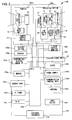
- the actuation unit 103 includes a CPU 103a that controls the device as a whole, a clock 103b that measures time, a power supply 103c for driving this portable telephone device with incorporated projector, a communication control unit 103d provided with an antenna 103e for communicating with a neighboring base station, an input device 103f provided with various types of button for the user to input telephone numbers or characters, a memory 103g for storing various types of data such as telephone directory data or the like, a memory card 103h for storing image data that has been photographed with the camera 102a, a TV tuner 103i for receiving TV broadcasts, a mike 103j for inputting voice utterances by the user, and an external interface 103k, that is an interface for connection to an external device.
- the display section includes the camera 102a, the projector device 102b, a liquid crystal monitor 102c that displays an image photographed (captured) by the camera unit 102a or a wallpaper screen or the like, a release button 102d that is actuated by the user when performing image photography (image-capturing) with the camera 102a, and a speaker 102e that outputs the voice utterances of the opposite party in a telephone conversation.
- the camera 102a includes a photographic lens 11, a CCD 12, a lens drive unit 13, and a camera control device 14.
- the photographic lens 11 is driven forward and backward by the lens drive unit 13, and is thereby capable of zooming in upon a photographic subject and zooming out therefrom. And, when the photographic lens 11 is oriented towards the photographic subject, photography is performed under conditions of exposure that are set according to the luminance of the photographic subject, and electric charges corresponding to an image of the photographic subject are accumulated upon the CCD 12, that is an image sensor (an image-capturing element). These electric charges accumulated upon the CCD 12 are converted into a digital signal by being A/D converted by a camera control device that includes a CPU and peripheral circuitry thereof. Thereafter various types of image processing are performed, such as white balance adjustment and image formatting that set in advance, for example compression formatting into the JPEG format or the like. The image data that has thus been image processed is stored in the memory 103g, and is simultaneously displayed upon the liquid crystal monitor 102c.
- This portable telephone device with incorporated projector 100 has the capability of selecting, as modes for photographing images with the camera 102a, a moving image (movie) photographic mode and a still image photographic mode. The user is able to select either of these photographic modes by using the input device 103f that is provided to the actuation unit 103.
- the moving image photographic mode has been selected by the user, then, when the release button 102d is depressed by the user at any desired timing during the above described through image display, during the time interval until the release button is next depressed, the through image that has been photographed is temporarily stored in a memory 104 as a moving image (movie). Thereafter, after various types of image processing have been performed upon this image, it is stored in the memory card 103h that is provided to the actuation unit 103.
- the still image photographic mode has been selected by the user, then, at the time point that the release button 102d is depressed by the user at any desired timing, the image that is being displayed upon the liquid crystal monitor 102c is photographed as a still image. This image that has been photographed is temporarily stored in the memory 104, and thereafter, after various types of image processing have been performed upon this image, it is stored in the memory card 103h that is provided to the actuation unit 103.
- the projector device 102b includes a LED light source 21, a liquid crystal panel 22 that displays an image, a projection lens 23 that is capable of projecting light that has been irradiated from the LED light source 21 and that has passed through the liquid crystal panel 22 upon a screen in magnified form, a LED drive unit 24 that supplies electrical current for causing the LED light source 21 to emit light, a liquid crystal drive unit 25 that drives the liquid crystal panel 22, a lens drive unit 26 that drives the projection lens 23 for focusing the image that is being projected, and a temperature sensor 27 that measures the temperature in the neighborhood of the installation position of the LED light source 21.
- the LED drive unit 24, the liquid crystal drive unit 25, and the lens drive unit 26 are controlled by a CPU 103a that will be described hereinafter, and that is mounted to the actuation unit 103.
- a high luminance type white colored LED that can be driven with a high electrical current is used in the LED light source 21.
- the light emitting portion is of a size of around 0.3 mm x 0.3 mm and is caused to emit light by a current flow of around 20 mA
- a high current type LED whose light emitting portion is of a large area of around 1 mm x 1 mm and that is caused to emit light by a high current flow of 200 mA ⁇ 350 mA. Due to this, nearly ten times the amount of light is obtained as compared to a normal LED.
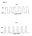
- the LED drive unit 24 drives the LED light source 21 by PWM drive, and is able to vary the light emission luminance of the LED light source 21 by changing the duty ratio. It should be understood that, in this first embodiment, it is possible to change over the light emission luminance (the brightness) of the LED light source 21 in two stages, i.e. between a "high” mode and a "low” mode: in the "high” mode, as shown in Fig. 3(a) , the duty ratio is in a 50% state, while in the "low” mode, as shown in Fig. 3(b) , the duty ratio is in a 20% state.
- the liquid crystal drive unit 25 generates a liquid crystal panel drive signal corresponding to the image data of the subject for projection that is transmitted from the CPU 103a, and displays an image of the subject for projection upon the liquid crystal panel 22 by driving the liquid crystal panel 22 with this generated drive signal.
- voltages corresponding to the image signal are applied to each pixel in the liquid crystal layer.
- the state of the liquid crystal molecules changes, and the optical transmittivity of this liquid crystal panel 22 changes. Due to these changes of transmittivity, an image is displayed upon the liquid crystal panel 22.
- the actuation unit 103 includes a CPU 103a that controls the device as a whole, a clock 103b that measures time, a power supply 103c for driving this portable telephone device with incorporated projector, a communication control unit 103d provided with an antenna 103e for communicating with a neighboring base station, an input device 103f provided with various types of button for the user to input telephone numbers or characters, a memory 103g for storing various types of data such as telephone directory data or the like, a memory card 103h for storing image data that has been photographed with the camera 102a, a TV tuner 103i for receiving TV broadcasts, a mike 103j for inputting voice utterances by the user, and an external interface 103k, that is an interface for connection to an external device.
- the CPU 103a When controlling the projector device 102b described above and projecting an image upon the screen, the CPU 103a, along with sending the image displayed by the user upon the liquid crystal monitor 102c to the liquid crystal drive unit 26 and displaying it upon the liquid crystal panel 22, also controls the LED drive unit 24 so as to irradiate light from the LED light source 21. Due to this, it is possible to display the image upon the screen in the same manner as with a normal projector. Furthermore, by performing digital processing upon the image data to be displayed, for example by performing LUT (Look Up Table) processing as described hereinafter, the CPU 103a is able to make the image brighter or darker, and moreover is able to perform contrast adjustment and/or color adjustment thereupon.
- LUT Look Up Table
- the light emission luminance of the LED light source 21 is varied by varying the duty ratio provided by the LED drive unit 24. If this duty ratio is decreased from 50% as when in the "high” mode to 20% as when in the "low” mode, and the luminance of the light that is irradiated from the LED light source 21 is thereby changed, then the luminance of the image that is projected upon the screen becomes darker.
- the CPU 103a performs LUT correction in advance upon the image data that is transmitted to the liquid crystal drive unit 25 and that is the subject for projection, and performs correction according to the change of luminance of the light that is irradiated from the LED light source 21, so that the image data becomes brighter.
- it performs processing as explained below in order to compensate for the fact that the duty ratio has become 30% darker, from 50% to 20%.
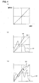
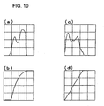
- a luminance histogram of the image may be created, and, based upon this histogram, a decision may be made as to whether or not the number of distributed data in a range that corresponds to 30% from the high luminance side (the bright side) is greater than or equal to a predetermined value.
- the slope of the linear LUT is changed as shown by the reference symbol 42, so as to compensate for a light reduction amount of 30%.
- correction is performed by applying this LUT to the image data of the subject for projection. Due to this, and taking into account the fact that the amount of data present in a range that corresponds to 30% from the bright side in a luminance histogram that is created according to image data is not generally very great, it is possible to perform correction in an appropriate manner so that only a few bright spots are introduced. In other words, the image data is corrected (compensated) with a linear coefficient.
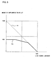
- the relationship between the luminance of the LED light source 21 and the amount of supplementation by the LUT, according to the above, is as shown in Fig. 5 .
- the relationship between the luminance of the LED light source 21 and the amount of LUT supplementation becomes as shown by the single dotted broken line denoted by the reference symbol 51.
- the LUT shows linear and the amount of supplementation with the LUT becomes zero, while if the light source is supposed to reduce by n%, the amount of supplementation is related thereto as being n%.
- the LUT changes according to the above described relationship that is close to a straight line, and it is arranged for the amount of supplementation to be suppressed the more, the brighter the light source becomes.
- an amount of supplementation of 40% may be taken as being a limit, and may be considered as saturation.
- the CPU 103a acquires the time instant at which the LED light source 21 starts emitting light and the time instant at which this light emission ends from the clock 103b, and stores the history thereof in the memory 103g. By doing this, it becomes possible to ascertain the time periods over which the LED light source 21 has emitted light and the time periods over which it has not emitted light, in other words, its history of periods of being extinguished and being illuminated.
- the user selects the image that is to be the subject for projection and displays it upon the liquid crystal monitor 102c.
- this image that is to be the subject for projection any one of a still image or a moving image stored upon the memory card 103h, an image including characters such as a received email or the like, or an image of a TV broadcast received by the TV tuner 103i, may be selected and displayed upon the liquid crystal monitor 102c as the subject for projection.
- the CPU 103a starts projecting the image by controlling the projector device 102b, simultaneously with also terminating the display thereof upon the liquid crystal monitor 102c.
- a high luminance type white colored LED that can be driven with a large electrical current is used as the LED light source 21 of the projector device 102b.
- the CPU 103a changes the projection method for the image, according to the type of image that is the subject for projection, based upon various types of temperature information that will be described hereinafter.
- the type of image that is the subject for projection is "still image”
- the following kind of thermal countermeasure processing is performed, using as temperature information the temperature in the neighborhood of the LED light source 21, that is outputted from the temperature sensor 27.
- the CPU 103a along with sending to the liquid crystal drive unit 26 image data for the still image that is to be the subject for projection and that is being displayed upon the liquid crystal panel 22, also controls the LED drive unit 24 so as to irradiate light from the LED light source 21 in the above described "high" mode.
- the CPU monitors the temperature in the neighborhood of the installation position of the LED light source 21, based upon the output from the temperature sensor 27. And, when the temperature in the neighborhood of the installation position of the LED light source 21 reaches an upper limit temperature that is set in advance, the CPU controls the LED drive unit 24 and gradually lowers the duty ratio of the LED light source 21 down to the above described "low" mode. By doing this, it is possible to suppress the heat which is generated from the LED light source 21.
- this upper limit temperature is set to a temperature (for example 80°C) that has been calculated by multiplying, by a fixed safety factor, the temperature for which, when the temperature in the neighborhood of the LED light source 21 rises to this temperature or greater, malfunctioning of the LED light source 21 or of its peripheral equipment takes place.
- LUT correction is performed upon the image data that is sent to the liquid crystal drive unit 26, so that the luminance of the image is changed.
- the image is LUT processed according to the amount of this darkening so that it becomes brighter; while, if the light that is being irradiated from the LED light source 21 has become brighter, the image is LUT processed according to the amount of this darkening so that it becomes darker.
- thermal countermeasure processing is performed using as temperature information the temperature in the neighborhood of the LED light source 21 that is outputted from the temperature sensor 27.
- the CPU 103a along with sending to the liquid crystal drive unit 26 image data for the screen displayed upon the liquid crystal monitor 102c in which the email that has been received by the user is shown, and displaying this image upon the liquid crystal panel 22, also performs the same processing as in the case (1).
- thermal countermeasure processing is performed by taking, as temperature information, the fact that the image that is the subject for projection is "moving image”.
- the CPU 103a controls the LED drive unit 24 so as to set the luminance of the light that is irradiated from the LED light source 21 to the above described "low” mode.
- the moving image data is sent to the liquid crystal drive unit 26 and is displayed upon the liquid crystal panel 22, so that thereby the moving image is projected.
- the CPU 103a detects the commercial portions of the TV broadcast that is received by the TV tuner 103i, and performs thermal countermeasure processing by taking these as temperature information.
- the CPU controls the LED drive unit 24 so as to set the luminance of the light irradiated from the LED light source 21 to the "low" mode, only during commercials.
- Fig. 7 is a flow chart showing processing performed by this portable telephone device with incorporated projector 100 according to the first embodiment.
- This processing in Fig. 7 constitutes a program that is started when the power supply to this portable telephone device with incorporated projector 100 is turned ON, and that is executed by the CPU 103a.
- a decision is made as to whether or not the start of projection of an image has been commanded by the user. If it is decided that the start of projection of an image has been commanded by the user then the flow of control proceeds to a step S20, and a decision is made as to whether or not the image that is to be the subject for projection has been selected by the user.
- step S21 If it is decided that the image that is to be the subject for projection has been selected by the user, then the flow of control proceeds to a step S21, and a backlight of the liquid crystal monitor 102c is turned OFF, and also display of images upon the liquid crystal monitor 102c is turned OFF. Thereafter the flow of control proceeds to a step S30.
- step S30 a decision is made as to the type of image that has been selected as the subject for projection. If it is decided that the type of the projection subject image is "still image” or "character image”, then the flow of control proceeds to a step S40.
- step S40 the LED drive unit 24 is controlled as described above, and the light emission luminance of the LED light source 21 is set to "high" mode, and then the flow of control proceeds to a step S50.
- step S50 image data for the image that is the subject for projection is transmitted to the liquid crystal drive unit 25, and the image is projected upon the screen. At this time, LUT correction is not performed upon the image data that is transmitted.
- step S60 in which a decision is made, based upon the output from the temperature sensor 27, as to whether or not the temperature in the neighborhood of the position in which the LED light source 21 is installed has arrived at an upper limit temperature that has been set in advance. If it is decided that the temperature in the neighborhood of the installation position of the LED light source 21 has arrived at the upper limit temperature, then the flow of control proceeds to a step S70.
- step S70 the LED drive unit 24 is controlled and the duty ratio of the LED light source 21 is gradually reduced to the "low" mode described above, and, along with this decrease of the duty ratio, LUT correction is performed upon the image data corresponding to the degree of this decrease.
- step S80 a decision is made, based upon the output from the temperature sensor 27, as to whether or not the temperature in the neighborhood of the installation position of the LED light source 21 has decreased as far as a lower limit temperature that has been set in advance. If it is decided that the temperature in the neighborhood of the installation position of the LED light source 21 has decreased as far as the lower limit temperature, then the flow of control proceeds to a step S90.
- step S90 the LED drive unit 24 is controlled and the duty ratio of the LED light source 21 is gradually increased to the "high” mode, and, along with this increase of the duty ratio, the LUT correction performed upon the image data is changed. And, at the time point that the system returns to the "high” mode, the LUT correction is stopped. Thereafter, the flow of control proceeds to a step S100.
- step S100 a decision is made as to whether or not termination of image projection has been commanded by the user, and if it is decided that termination has not been commanded, then the flow of control returns to the step S60. If, on the other hand, it is decided that termination has been commanded, then the flow of control is transferred to a step S220 that will be described hereinafter.
- step S110 the LED drive unit 24 is controlled and the light emission luminance of the LED light source 21 is set to the "low” mode, and then the flow of control proceeds to a step S120.
- step S120 in order to mitigate the fact that the image that is being projected becomes darker due to the fact that the light emission luminance of the LED light source 21 has been set to the "low” mode, the above described LUT correction is performed upon the moving image data of the subject for projection, and then the flow of control proceeds to a step S130.
- step S130 the moving image data of the subject for projection is transmitted to the liquid crystal drive unit 25 so as to project the moving image upon the screen, and then the flow of control proceeds to a step S140.
- step S140 a decision is made as to whether or not termination of image projection has been commanded by the user, and if it is decided that termination has been commanded, then the flow of control is transferred to the step S220 that will be described hereinafter.
- step S150 the LED drive unit 24 is controlled and the light emission luminance of the LED light source 21 is set to the "high” mode, and then the flow of control proceeds to a step S160.
- step S160 the TV broadcast image data that has been received by the TV tuner 103i is transmitted to the liquid crystal drive unit 25 so as to project the TV broadcast image upon the screen.
- step S170 the flow of control proceeds to a step S170, in which commercials are detected by detecting the stereo signal from the TV broadcast image data that is received. And if it has been decided that a commercial has been detected, then the flow of control proceeds to a step S180.
- step S180 the LED drive unit 24 is controlled and the light emission luminance of the LED light source 21 is set to the "low" mode, and then the flow of control proceeds to a step S190.
- step S190 a decision is made as to whether or not the commercial has ended, in other words whether the detection of the commercial has ended or not. If it has been decided that the commercial has ended, then the flow of control proceeds to a step S200.
- step S200 the LED drive unit 24 is controlled and the light emission luminance of the LED light source 21 is returned to the "high” mode, and then the flow of control proceeds to a step S210.
- step S210 a decision is made as to whether or not termination of image projection has been commanded by the user, and if it is decided that termination has not been commanded, then the flow of control returns to the step S170. If, on the other hand, it is decided that termination has been commanded, then the flow of control is transferred to the step S220.
- step S220 the LED drive unit 24 is controlled and the irradiation of light from the LED light source 21 is terminated, and the projector is turned OFF. Thereafter the flow of control proceeds to a step S230, in which a backlight of the liquid crystal monitor 102c is turned ON or the like and the display of the image upon the liquid crystal monitor 102c is turned ON, and then the flow of control proceeds to a step S240.
- step S240 a decision is made as to whether or not the power supply to this portable telephone device with incorporated projector 100 has been turned OFF by the user, and, if it is decided that the power supply has not been turned OFF, then the flow of control is returned to the step S10 and the processing described above is repeated. On the other hand, if it has been decided that the power supply to this portable telephone device with incorporated projector 100 has been turned OFF by the user, then processing is terminated.
- the luminance of the light that is irradiated from the LED light source 21 during image projection is controlled, not using the temperature of the LED light source 21 as detected by the temperature sensor 27, but rather using the temperature in the neighborhood of the LED light source 21 as estimated based upon the light emission history of the LED light source 21, this history being stored in the memory 103g.
- the LED light source 21 is extinguished so as to turn OFF the projector, and instead the image is displayed upon the liquid crystal monitor 102c, so that thereby the temperature in the neighborhood of the LED light source 21 is decreased.
- the CPU 103a estimates the temperature in the neighborhood of the LED light source 21 based upon the light emission history of the LED light source 21 that has been stored in the memory 103g, and drive controls the LED drive unit 24 based upon the result thereof. It should be understood that the LED drive unit 24 controls the light emission luminance of the LED light source 21 to any one of three states: the above described "high” mode, the above described "low” mode, and a state of being turned out.
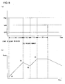
- the CPU 103a reads in the light emission history for the directly preceding five minutes, and, if the LED light source 21 did not emit light during this time, in other words if the LED light source 21 has been extinguished continuously for greater than or equal to five minutes, then the CPU estimates that the temperature in the neighborhood of the LED light source 21 is at an initial temperature that is set in advance, for example 30°C. This is done in consideration of the fact that generally, if the LED light source 21 has been extinguished continuously for greater than or equal to five minutes, the temperature in the neighborhood of the LED light source 21 will have become the same as an initial temperature that is equal to the temperature around it, due to natural air cooling. On the other hand, if the LED light source 21 has emitted light during the directly preceding five minutes, then a current estimated temperature is calculated by a method that will be described hereinafter.
- the LED light source 21 is emitting light in either the "high” mode or the “low” mode, and, based upon its light emitting state, the current temperature in the neighborhood of the LED light source 21 is estimated.
- the current temperature in the neighborhood of the LED light source 21 is estimated.
- the heat generation is also greater.
- the LED light source is turned off, it is subject to natural air cooling.
- the amount of change of the temperature in each of the modes may be, for example ,defined as follows.
- the temperature in the neighborhood of the LED light source 21 increases at the rate of 2°C per second.
- the temperature in the neighborhood of the LED light source 21 does not change.
- the temperature in its neighborhood decreases at the rate of 1°C per second.
- the estimated temperature calculated according to Equation (1) is less than the initial temperature, then the estimated temperature is corrected to being the initial temperature. This is because the temperature does not drop indefinitely, even if natural air cooling continues; rather, the temperature stabilizes at the initial temperature that is compatible with the surrounding temperature.
- this upper limit temperature is set to a temperature, for example 80°C, that has been calculated by multiplying, by a fixed safety factor, the temperature for which, when the temperature in the neighborhood of the LED light source 21 rises to this temperature or greater, malfunctioning of the LED light source 21 or of its peripheral equipment takes place.
- the estimated temperature in the neighborhood of the LED light source 21 changes from the start of light emission until the present moment as shown in Fig. 8(b) , and the current estimated temperature becomes 60°C. If in this state, as shown in Fig. 8(a) , light emission is again started from the present moment in the "high” mode, it is possible to estimate that after ten seconds the upper limit temperature of 80°C will be reached. And, after this ten seconds has actually elapsed from the present moment, when the estimated temperature in the neighborhood of the LED light source 21 has arrived at 80°C, the LED drive unit 24 is controlled so as to transition to the "low” mode, in order to prevent the temperature from rising further.
- LUT correction is performed in order to maintain the luminance of the image that is being projected, in the same manner as in the case of the first embodiment.
- a warning sound is outputted via the speaker 102e.
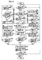
- Fig. 9 is a flow chart showing processing performed by the portable telephone device with incorporated projector 100 according to the second embodiment.
- This processing in Fig. 9 constitutes a program that is started when the power supply to this portable telephone device with incorporated projector 100 is turned ON, and that is executed by the CPU 103a.
- the same step numbers are affixed, and explanation thereof is omitted; only the points of difference will be explained.
- step S41 based upon the light emission history of the LED light source 21 that is stored in the memory 103g, the current temperature in the neighborhood of the LED light source 21 is estimated. Then the flow of control proceeds to a step S42.
- step S42 a decision is made as to whether or not this estimated current temperature in the neighborhood of the LED light source 21 has arrived at an upper limit temperature that has been set in advance. If it is decided that the estimated current temperature in the neighborhood of the LED light source 21 has not arrived at the upper limit temperature set in advance, then the flow of control proceeds to a step S43, and the LED drive unit 24 is controlled so as to irradiate light from the LED light source 21 in the "high" mode, so as to project the image that is the subject for projection; and then the flow of control returns to the step S41.
- step S44 the display on the liquid crystal monitor 102c is turned ON and the flow of control proceeds to a step S45.
- step S45 in order to notify the user to the effect that the system has transitioned to the "low” mode, along with displaying a warning message upon the liquid crystal monitor 102c, also a warning sound is outputted via the speaker 102e.
- the flow of control proceeds to the step S70 and the LED drive unit 24 is controlled so that the duty ratio of the LED light source 21 gradually is reduced towards the "low” mode described above, and, along with this decrease in the duty ratio, LUT correction is performed upon the image data to an extent corresponding to the degree of this decrease.
- step S170 if in the step S170 a commercial has been detected, then the flow of control is transferred to a step S181.
- step S181 the LED drive unit 24 is controlled to extinguish the LED light source 21 so that the projector is turned OFF, and instead the backlight of the liquid crystal monitor 102c is turned ON and the image is displayed upon the liquid crystal monitor 102c, and then the flow of control proceeds to the step S190.
- step S190 if the end of the commercial has been detected, the flow of control is transferred to a step S191, and the LED drive unit 24 is controlled to return the LED light source 21 to the "high" mode so that the projector is turned ON, and the backlight of the liquid crystal monitor 102c is turned OFF and the display of the image upon the liquid crystal monitor 102c is terminated.
- a third embodiment it is arranged to fade in and to fade out the image by changing the luminance of the light that is irradiated from the LED light source 21 during image projection.
- a figure showing the external appearance of this portable telephone device with incorporated projector, and a block diagram thereof, are here omitted, since they would be the same as Fig. 1 and Fig. 2 that have been explained in relation to the first embodiment.
- the LED drive unit 24 controls the drive electrical power of the LED light source 21 by PWM drive, and is able to vary the light emission luminance of the LED light source 21 by varying the duty ratio. For example, to compare the case, as shown in Fig. 3(a) for the first embodiment, in which the duty ratio is set to 50%, with the case of the duty ratio being set to 20% as shown in Fig. 3(b) , in the case where the duty ratio is set to 50%, the light that is irradiated from the LED light source 21 becomes brighter.
- the state in which the above described duty ratio is 50% is defined as being the "bright state", while the state in which the above described duty ratio is 20% is defined as being the “dark state”.
- the LED drive unit 24 is able to vary the duty ratio continuously, so that it is possible for the luminance of the LED light source 21 to be continuously changed from the "bright state” to the "dark state”. Since due to this the luminance of the object varies, accordingly it is sufficient simply to vary the duty ratio, and processing for applying luminance modulation to the image data becomes unnecessary, so that it is possible to reduce the load upon the CPU 103a.
- the liquid crystal drive unit 25 generates a liquid crystal panel drive signal according to the data for the image that is to be the subject for replay, transmitted from the CPU 103a, and displays the image that is the subject for replay upon the liquid crystal panel 22 by driving the liquid crystal panel 22 with this generated drive signal.
- it applies a voltage according to the image signal to each pixel in the liquid crystal layer.
- the state of the liquid crystal molecules in the liquid crystal layer to which voltage has been applied changes, so that the transmittivity to light of the liquid crystal panel changes. Due to this change of transmittivity, the image is displayed upon the liquid crystal panel 22.
- the CPU 103a along with sending the image that has been selected by the user to the liquid crystal drive unit 26 and displaying it upon the liquid crystal panel 22, also controls the LED drive unit 24 so as to irradiate light from the LED light source 21.
- the CPU 103a c controls the LED drive unit 24 as described below, so as to fade in and fade out the image that is projected upon the screen, thus imparting a beneficial visual sensation.
- the CPU 103a controls the LED drive unit 24 so as to set the luminance of the LED light source 21 to the above described "dark state” when starting display of the image, and thereafter controls it so as to change the luminance gradually towards the "bright state".
- the CPU 103a controls the LED drive unit 24 and thereby sets the above described duty ratio to 20%, and thereafter increases the duty ratio at a constant rate until it reaches 50%. Since, by doing this, the image that is projected upon the screen at the start of display is dark, and thereafter the image is gradually displayed brighter and brighter, accordingly it is possible to impart the beneficial visual sensation of fading it in.
- the CPU 103a controls the LED drive unit 24 so as to set the luminance of the LED light source 21 to the above described " bright state” when starting display of the image, and thereafter controls it so as to change the luminance gradually towards the "dark state".
- the CPU 103a controls the LED drive unit 24 and thereby sets the above described duty ratio to 50%, and thereafter decreases the duty ratio at a constant rate until it reaches 20%. Since, by doing this, the image that is projected upon the screen at the start of display is bright, and thereafter the image is gradually displayed darker and darker, accordingly it is possible to impart the beneficial visual sensation of fading it out.
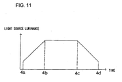
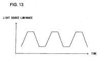
- Fig. 11 is a figure showing the change over time of the luminance of the LED light source 21, when fade in and fade out are both performed for a single image.
- the luminance of the LED light source 21 is set to the "dark state", and thereafter is gradually brightened at a constant rate, so that it is set to the "bright state” at the time point 4b.
- the LED light source is darkened at a constant rate from the time point 4c, and when it reaches the "dark state" at the time point 4d, at the same time the projection of the image is terminated.
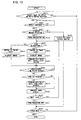
- Fig. 12 is a flow chart showing processing performed by the portable telephone device with incorporated projector 100 according to this embodiment.
- This processing in Fig. 12 constitutes a program that is started when the power supply to this portable telephone device with incorporated projector 100 is turned ON, and that is executed by the CPU 103a.
- a decision is made as to whether or not the image that is to be the subject of replay has been selected by the user, and as to whether or not a replay method for either projecting it with the projector device 102b or displaying it upon the liquid crystal monitor 102c has been selected. If it is decided that the selection of the image that is to be the subject of replay, and also the selection of the replay method, have been performed, then the flow of control proceeds to a step S320.
- a decision is made as to whether or not replay of the image that has been selected by the user has been commanded by the user or not, and if it is decided that replay has been commanded, then the flow of control proceeds to a step S321.
- step S321 it is decided whether or not the replay method that has been selected by the user is projection with the projector device 102b. If it is decided that the replay method that has been selected by the user is not projection with the projector device 102b, then the flow of control proceeds to a step S323, and the image that is to be the subject for replay is displayed upon the liquid crystal monitor 102c, and then the flow of control is transferred to a step S440 that will be described hereinafter. On the other hand, if it is decided that the replay method that has been selected by the user is projection with the projector device 102b, then the flow of control proceeds to a step S322. In this step S322, the LED drive unit 24 is controlled so as to irradiate light from the LED light source 21, and the projector is automatically turned ON. Thereafter, the flow of control proceeds to a step S330.
- step S330 a decision is made as to whether or not fade in is required, in other words as to whether or not it has been set in advance by the user to perform fading in. If it is decided that it has not been set in advance by the user to perform fading in, then the flow of control proceeds to a step S340.
- step S340 the LED drive unit 24 is controlled so as to set the luminance of the LED light source 21 to the "bright state", and then the flow of control proceeds to a step S350.
- step S350 the data for the image that is the subject for replay is transmitted to the liquid crystal drive unit 25, so as to display this image upon the screen. And thereafter, the flow of control is transferred to a step S390 that will be described hereinafter.
- step S360 the LED drive unit 24 is controlled so as to set the luminance of the LED light source 21 to the "dark state”. Thereafter, the flow of control proceeds to a step S370, and the data for the image that is the subject for replay is transmitted to the liquid crystal drive unit 25, so as to display this image upon the screen, and then the flow of control proceeds to a step S380.
- step S380 the LED drive unit 24 is controlled so as to increase the duty ratio of the luminance of the LED light source 21 at a constant rate, until this luminance reaches the "bright state", and then the flow of control proceeds to the step S390.
- step S390 a decision is made as to whether or not the time period over which projection has been performed in the "bright state” has reached a predetermined time period that has been determined in advance. If it is decided that the time period over which projection has been performed in the "bright state” has reached the predetermined time period, then the flow of control proceeds to a step S400.
- step S400 a decision is made as to whether or not fade out is required, in other words as to whether or not a command has been issued by the user to perform fading out. If it is decided that it has not been set in advance by the user to perform fading out, then the flow of control proceeds to a step S420 that will be described hereinafter.
- step S410 the LED drive unit 24 is controlled so as to decrease the luminance of the LED light source 21 at a constant rate, until this luminance reaches the "dark state", and then the flow of control proceeds to the step S420.
- step S420 the transmission of the image data for the subject for replay to the liquid crystal drive unit 25 is stopped, and the projection of the image is terminated. Thereafter, the flow of control proceeds to a step S430.
- step S430 if a plurality of images have been selected by the user as images that are to be the subjects for replay, a decision is made as to whether or not a subsequent image that is to be a subject for replay is present. If it has been decided that a subsequent image that is to be a subject for replay is present, then the flow of control returns to the step S330, and the above described processing is performed for the subsequent image.
- step S431 the LED drive unit 24 is controlled so as to stop the irradiation of light from the LED light source 21, so that the projector is automatically turned OFF. Thereafter, the flow of control proceeds to the step S440.
- step S440 a decision is made as to whether or not the mode of this portable telephone device with incorporated projector 100 has been changed by the user to some mode other than image replay, and if it is decided that such a change has not been made, then the flow of control returns to the step S310 and the processing described above is repeated. On the other hand, if it is decided that the mode of this portable telephone device with incorporated projector 100 has been changed by the user to some mode other than image replay, then processing terminates.
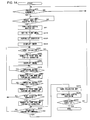
- Fig. 14 is a flow chart showing processing performed by a portable telephone device with incorporated projector 100 according to this fourth embodiment.
- This processing shown in Fig. 14 constitutes a program that is started when the power supply to this portable telephone device with incorporated projector 100 is turned ON, and that is executed by the CPU 103a. It should be understood that, to steps for which the processing details are the same as in the processing for the first embodiment shown in Fig. 7 , the same step numbers are affixed.
- step S310 the LED drive unit 24 is controlled and the light emission luminance of the LED light source 21 is temporarily set to the "low” mode, and then the flow of control proceeds to a step S320.
- step S320 in order to mitigate the fact that the image that is being projected has become darker due to the light emission luminance of the LED light source 21 having been put down to the "low” mode, the above described LUT correction is performed upon the moving image data that is the subject for projection, and then the flow of control proceeds to a step S330.
- step S330 the data for the image that is the subject for projection is transmitted to the liquid crystal drive unit 25, so that the image is projected upon the screen.
- step S340 a decision is made as to whether or not the user has actuated a "high” mode button (i.e. a "bright” mode button). Any one of the buttons upon the input device 103f may be allocated as this "high” mode button.
- the "high” mode is commanded while the user presses the "high” mode button continuously, and, when he releases the "high” mode button, the system returns to the "low” mode.
- step S340 If, in this step S340, it is decided that the user is actuating (pressing) the "high" mode button, then the flow of control proceeds to a step S350; while, if it is decided that he is not performing such actuation, then the flow of control is transferred to a step S430.
- step S350 the LED drive unit 24 is controlled and the duty ratio of the LED light source 21 is gradually raised to the "high” mode, and, along with this elevation of the duty ratio, the LUT correction upon the image data is changed. And, at the time point that the system has returned to the "high” mode, the LUT correction is stopped. Thereafter, the flow of control proceeds to a step S360.
- step S360 the data for the image that is to be the subject for projection is transmitted to the liquid crystal drive unit 25, and the image is projected upon the screen.
- step S370 a decision is made, based upon the output from a temperature sensor 27, as to whether or not the temperature in the neighborhood of the installation position of the LED light source 21 has reached an upper limit temperature that is set in advance. If it is decided that the temperature in the neighborhood of the installation position of the LED light source 21 has reached the upper limit temperature, then the flow of control proceeds to a step S380.
- step S380 the LED drive unit 24 is controlled and the duty ratio of the LED light source 21 is gradually reduced to the above described "low" mode, and, along with this decrease of the duty ratio, LUT correction is performed upon the image data according to the degree of this decrease.
- the flow of control proceeds to a step S390, and a decision is made, based upon the output from a temperature sensor 27, as to whether or not the temperature in the neighborhood of the installation position of the LED light source 21 has decreased as far as a lower limit temperature that is set in advance. If it is decided that the temperature in the neighborhood of the installation position of the LED light source 21 has decreased as far as the lower limit temperature, then the flow of control proceeds to a step S400.
- step S400 the LED drive unit 24 is controlled and the duty ratio of the LED light source 21 is gradually increased to the above described "high” mode, and, along with this increase of the duty ratio, the LUT correction performed upon the image data is changed. And, at the time point that the system has returned to the "high” mode, the LUT correction is stopped. Thereafter, the flow of control proceeds to a step S410.
- step S410 a decision is made as to whether or not the user is not actuating the "high” mode button. In other words, it is decided whether or not the user has released the "high” mode button, thus stopping his commanding of the "high” mode. If it is decided that the user has stopped commanding the "high” mode, then the flow of control proceeds to a step S420; while, if it is decided that he is not thus stopping commanding, then the flow of control returns to the step S340 and the above processing is repeated.
- step S420 the LED drive unit 24 is controlled and the duty ratio of the LED light source 21 is gradually reduced to the "low” mode, and, along with this reduction of the duty ratio, LUT correction is performed upon the image data according to the degree of this decrease. Thereafter, the flow of control proceeds to a step S430.
- step S430 a decision is made as to whether or not termination of projection of the image has been commanded by the user, and, if it is decided that termination has not thus been commanded, then the flow of control returns to the step S340. By contrast, if it is decided that termination has been commanded, then the flow of control proceeds to a step S220.
- step S220 the LED drive unit 24 is controlled to end the irradiation of light from the LED light source 21, so that the projector is turned OFF. Thereafter, flow of control proceeds to a step S230, and the backlight of the liquid crystal monitor 102c is turned ON so that the image is displayed upon the liquid crystal monitor 102c, and then the flow of control proceeds to a step S240.
- step S240 a decision is made as to whether or not the power supply to this portable telephone device with incorporated projector 100 has been turned OFF by the user, and, if it is decided that the power supply has not been turned OFF, then the flow of control is returned to the step S10 and the processing described above is repeated. On the other hand, if it has been decided that the power supply to this portable telephone device with incorporated projector 100 has been turned OFF by the user, then processing is terminated.
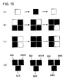
- Fig. 15 is a figure showing variant embodiments for providing a beneficial visual sensation.
- Fig. 15(a) shows an example in which the LED is blinked, and its period is changed. It would also be acceptable to arranged to change this period in correlation with outputting music from the portable telephone.
- Fig. 15(b) shows an example in which the spots at which a plurality of LEDs are lit up are changed around and around.
- Fig. 15(c) shows an example in which the spots at which a plurality of LEDs are lit up are gradually changed.
- Fig. 15(d) shows an example in which the combination in which red, blue, and green LEDs are lit up is changed. By doing this, it is possible to change the white balance by only darkening a specified color. Furthermore, it also becomes possible to change the color while blinking the display.
Landscapes
- Physics & Mathematics (AREA)
- General Physics & Mathematics (AREA)
- Engineering & Computer Science (AREA)
- Multimedia (AREA)
- Signal Processing (AREA)
- Projection Apparatus (AREA)
- Transforming Electric Information Into Light Information (AREA)
- Control Of Indicators Other Than Cathode Ray Tubes (AREA)
Applications Claiming Priority (3)
| Application Number | Priority Date | Filing Date | Title |
|---|---|---|---|
| JP2004341522A JP4158761B2 (ja) | 2004-11-26 | 2004-11-26 | プロジェクタ装置 |
| JP2004341523A JP4270114B2 (ja) | 2004-11-26 | 2004-11-26 | プロジェクタ装置 |
| EP05809488.9A EP1830225B1 (de) | 2004-11-26 | 2005-11-25 | Projektoreinrichtung |
Related Parent Applications (2)
| Application Number | Title | Priority Date | Filing Date |
|---|---|---|---|
| EP05809488.9A Division EP1830225B1 (de) | 2004-11-26 | 2005-11-25 | Projektoreinrichtung |
| EP05809488.9 Division | 2005-11-25 |
Publications (3)
| Publication Number | Publication Date |
|---|---|
| EP2455808A2 true EP2455808A2 (de) | 2012-05-23 |
| EP2455808A3 EP2455808A3 (de) | 2014-01-29 |
| EP2455808B1 EP2455808B1 (de) | 2015-04-15 |
Family
ID=36498062
Family Applications (2)
| Application Number | Title | Priority Date | Filing Date |
|---|---|---|---|
| EP05809488.9A Expired - Lifetime EP1830225B1 (de) | 2004-11-26 | 2005-11-25 | Projektoreinrichtung |
| EP11192048.4A Expired - Lifetime EP2455808B1 (de) | 2004-11-26 | 2005-11-25 | Projektorvorrichtung |
Family Applications Before (1)
| Application Number | Title | Priority Date | Filing Date |
|---|---|---|---|
| EP05809488.9A Expired - Lifetime EP1830225B1 (de) | 2004-11-26 | 2005-11-25 | Projektoreinrichtung |
Country Status (3)
| Country | Link |
|---|---|
| US (1) | US8454172B2 (de) |
| EP (2) | EP1830225B1 (de) |
| WO (1) | WO2006057328A1 (de) |
Families Citing this family (16)
| Publication number | Priority date | Publication date | Assignee | Title |
|---|---|---|---|---|
| US20110310357A1 (en) * | 2004-11-15 | 2011-12-22 | Kuo-Ching Chiang | Multiple rate projector |
| JP5286772B2 (ja) | 2007-12-18 | 2013-09-11 | セイコーエプソン株式会社 | 画像表示装置 |
| JP4488253B2 (ja) * | 2008-02-08 | 2010-06-23 | セイコーエプソン株式会社 | 表示装置、画像供給装置、表示システム、プログラム、情報記憶媒体および制御方法 |
| KR101590940B1 (ko) * | 2008-12-09 | 2016-02-03 | 삼성디스플레이 주식회사 | 광원 구동 방법, 이를 수행하기 위한 광원 장치 및 이를 포함하는 표시 장치 |
| CN101788744B (zh) * | 2009-01-23 | 2012-08-22 | 上海三鑫科技发展有限公司 | 微型投影机的驱动装置及驱动方法 |
| JP5287378B2 (ja) * | 2009-03-12 | 2013-09-11 | カシオ計算機株式会社 | 投影装置、投影方法及びプログラム |
| US20120050351A1 (en) * | 2009-05-15 | 2012-03-01 | Osram Ag | Method for operating a projector having a high-pressure discharge lamp |
| TWI403903B (zh) * | 2009-06-16 | 2013-08-01 | Acer Inc | 電子系統、資訊輸出裝置及資訊輸出裝置的啟動方法 |
| JP5523750B2 (ja) * | 2009-06-26 | 2014-06-18 | 京セラ株式会社 | 携帯電子機器 |
| FR2973127B1 (fr) * | 2011-03-24 | 2013-04-26 | Distech Controls Sas | Methode de gestion de l'affichage d'un afficheur retro-eclaire et unite de commande comprenant un tel afficheur |
| JP6086282B2 (ja) * | 2012-07-05 | 2017-03-01 | 株式会社リコー | 画像投影装置 |
| KR20150128467A (ko) * | 2014-05-09 | 2015-11-18 | 삼성전자주식회사 | 프로젝터를 가지는 전자 장치 및 이의 색 보정 방법 |
| US9551916B2 (en) * | 2014-09-25 | 2017-01-24 | Intel Corporation | Integrated and adjustable image projection with auto-image correction in electronic devices using an in-facing or world-facing image projector |
| WO2016179542A1 (en) | 2015-05-06 | 2016-11-10 | Dolby Laboratories Licensing Corporation | Thermal compensation in image projection |
| WO2020017403A1 (ja) * | 2018-07-20 | 2020-01-23 | ソニー株式会社 | 画像表示装置及び画像表示方法 |
| CN114077133B (zh) | 2020-08-12 | 2023-05-26 | 中强光电股份有限公司 | 投影装置及其控制方法 |
Citations (4)
| Publication number | Priority date | Publication date | Assignee | Title |
|---|---|---|---|---|
| JP2000236375A (ja) | 1999-02-12 | 2000-08-29 | Matsushita Electric Ind Co Ltd | プロジェクタ付携帯電話装置 |
| JP2001204044A (ja) | 2000-01-24 | 2001-07-27 | Victor Co Of Japan Ltd | 画像処理方法および画像処理装置 |
| JP2004341522A (ja) | 2003-05-13 | 2004-12-02 | Hewlett-Packard Development Co Lp | 照明源における傾斜の検知 |
| JP2004341523A (ja) | 2003-05-13 | 2004-12-02 | Hewlett-Packard Development Co Lp | 定着器 |
Family Cites Families (32)
| Publication number | Priority date | Publication date | Assignee | Title |
|---|---|---|---|---|
| JPS58135168U (ja) | 1982-03-04 | 1983-09-10 | ソニー株式会社 | 特殊効果装置 |
| JP3216644B2 (ja) | 1990-03-09 | 2001-10-09 | オリンパス光学工業株式会社 | 実像投影式映像再生装置及び該装置に適用するための制御信号形成装置 |
| JPH04319930A (ja) * | 1991-04-19 | 1992-11-10 | Matsushita Electric Ind Co Ltd | ライトバルブ映像投写器の映像制御装置 |
| JP3331578B2 (ja) * | 1994-11-18 | 2002-10-07 | 富士写真フイルム株式会社 | 磁気記録層を有するフイルムのフイルムビューア |
| JP3226450B2 (ja) | 1995-11-30 | 2001-11-05 | ウエスト電気株式会社 | 遊戯機用液晶プロジェクタ |
| JPH1062865A (ja) | 1996-08-20 | 1998-03-06 | Hitachi Ltd | 表示装置及び表示方法 |
| JPH1074049A (ja) | 1996-08-30 | 1998-03-17 | Matsushita Electric Works Ltd | 液晶表示装置 |
| JPH10222131A (ja) | 1997-02-06 | 1998-08-21 | Matsushita Electric Ind Co Ltd | 投写型画像表示装置 |
| JP2000194070A (ja) * | 1998-12-28 | 2000-07-14 | Fujitsu Ltd | 投写型表示装置 |
| JP2001024926A (ja) | 1999-07-09 | 2001-01-26 | C Media:Kk | 携帯型カメラ、及び画像通信方法 |
| JP2001021992A (ja) * | 1999-07-09 | 2001-01-26 | C Media:Kk | 携帯型端末、携帯型端末システム及び携帯電話 |
| US6969960B2 (en) * | 1999-09-10 | 2005-11-29 | Belliveau Richard S | Image projection lighting device |
| JP2002015057A (ja) | 2000-04-28 | 2002-01-18 | Valis:Kk | 系図、個人史の作成システム |
| JP2002258406A (ja) * | 2001-03-06 | 2002-09-11 | Matsushita Electric Ind Co Ltd | 投写型表示装置 |
| JP3471772B2 (ja) | 2001-07-26 | 2003-12-02 | Necビューテクノロジー株式会社 | プロジェクタ |
| US7391475B2 (en) * | 2002-01-31 | 2008-06-24 | Hewlett-Packard Development Company, L.P. | Display image generation with differential illumination |
| US7283181B2 (en) * | 2002-01-31 | 2007-10-16 | Hewlett-Packard Development Company, L.P. | Selectable color adjustment for image display |
| JP3960142B2 (ja) | 2002-06-24 | 2007-08-15 | セイコーエプソン株式会社 | 画像表示装置、プロジェクタ、プログラム及び記憶媒体 |
| JP2004061779A (ja) | 2002-07-26 | 2004-02-26 | Yoshio Monjo | プロジェクタ |
| JP3792641B2 (ja) | 2002-11-13 | 2006-07-05 | Necビューテクノロジー株式会社 | プロジェクタ装置の冷却方法およびプロジェクタ装置 |
| US7388612B2 (en) * | 2002-11-26 | 2008-06-17 | Canon Kabushiki Kaisha | Image pickup apparatus and method, recording medium, and program providing user selected hue and white balance settings |
| CN100424547C (zh) | 2002-12-26 | 2008-10-08 | 三洋电机株式会社 | 投影式视频显示器 |
| JP4185778B2 (ja) | 2003-01-17 | 2008-11-26 | 株式会社リコー | 画像再生装置、再生方法、再生プログラム、およびその記録媒体 |
| JP4179456B2 (ja) | 2003-01-21 | 2008-11-12 | 株式会社バンダイ | デジタルカメラ、及びそれに用いられるプログラム |
| JP4604448B2 (ja) * | 2003-01-22 | 2011-01-05 | セイコーエプソン株式会社 | プロジェクタ |
| JP2004302254A (ja) * | 2003-03-31 | 2004-10-28 | Seiko Epson Corp | 投射型表示装置 |
| JP3909595B2 (ja) | 2003-04-23 | 2007-04-25 | セイコーエプソン株式会社 | 表示装置、及びその調光方法 |
| JP4478414B2 (ja) * | 2003-07-31 | 2010-06-09 | キヤノン株式会社 | 投射型画像表示装置 |
| US7289090B2 (en) * | 2003-12-10 | 2007-10-30 | Texas Instruments Incorporated | Pulsed LED scan-ring array for boosting display system lumens |
| US6992811B2 (en) * | 2004-02-03 | 2006-01-31 | Hewlett-Packard Development Company, L.P. | Display device |
| EP1725901A1 (de) * | 2004-03-16 | 2006-11-29 | Sign-Tronic AG | Verfahren zum aufbau eines lichtbündels mit im wesentlichen konstanter lichtstärke |
| US7461939B2 (en) * | 2004-11-19 | 2008-12-09 | Hewlett-Packard Development Company, L.P. | Automatic zoom for screen fitting |
-
2005
- 2005-11-25 EP EP05809488.9A patent/EP1830225B1/de not_active Expired - Lifetime
- 2005-11-25 WO PCT/JP2005/021661 patent/WO2006057328A1/ja not_active Ceased
- 2005-11-25 US US11/660,215 patent/US8454172B2/en not_active Expired - Fee Related
- 2005-11-25 EP EP11192048.4A patent/EP2455808B1/de not_active Expired - Lifetime
Patent Citations (4)
| Publication number | Priority date | Publication date | Assignee | Title |
|---|---|---|---|---|
| JP2000236375A (ja) | 1999-02-12 | 2000-08-29 | Matsushita Electric Ind Co Ltd | プロジェクタ付携帯電話装置 |
| JP2001204044A (ja) | 2000-01-24 | 2001-07-27 | Victor Co Of Japan Ltd | 画像処理方法および画像処理装置 |
| JP2004341522A (ja) | 2003-05-13 | 2004-12-02 | Hewlett-Packard Development Co Lp | 照明源における傾斜の検知 |
| JP2004341523A (ja) | 2003-05-13 | 2004-12-02 | Hewlett-Packard Development Co Lp | 定着器 |
Also Published As
| Publication number | Publication date |
|---|---|
| EP1830225A1 (de) | 2007-09-05 |
| EP2455808A3 (de) | 2014-01-29 |
| EP2455808B1 (de) | 2015-04-15 |
| US20080094579A1 (en) | 2008-04-24 |
| US8454172B2 (en) | 2013-06-04 |
| EP1830225B1 (de) | 2013-12-25 |
| EP1830225A4 (de) | 2009-11-04 |
| WO2006057328A1 (ja) | 2006-06-01 |
Similar Documents
| Publication | Publication Date | Title |
|---|---|---|
| EP1830225B1 (de) | Projektoreinrichtung | |
| JP5072087B2 (ja) | 液晶表示装置および液晶表示方法 | |
| US9583068B2 (en) | Image display apparatus and method of controlling image display apparatus | |
| US9608726B2 (en) | Display device | |
| JP2005260733A (ja) | 撮影装置及びその制御方法 | |
| US7436446B2 (en) | Imaging device equipped with automatic exposure control function | |
| US10645303B2 (en) | Imaging device | |
| US8908077B2 (en) | Projection device with display monitor | |
| JP4158761B2 (ja) | プロジェクタ装置 | |
| JP2009192853A (ja) | 自動調光システム | |
| CN107896322B (zh) | 投影装置、投影装置的控制方法以及存储介质 | |
| JP4619160B2 (ja) | 画像表示装置及び画像表示方法 | |
| JP5863518B2 (ja) | マルチディスプレイシステムおよびマルチディスプレイシステムにおける明るさ調整方法 | |
| JP2007065608A (ja) | 画像コントラストを向上する装置及び方法 | |
| JP2010091596A (ja) | 表示装置、撮像装置およびプロジェクタ | |
| EP1903554A2 (de) | Flüssigkristallanzeigeeinheit und Flüssigkristallfernsehgerät | |
| CN106055291B (zh) | 图像显示设备和图像显示设备的控制方法 | |
| JP2017173414A (ja) | 光源点灯装置、表示装置、および、テレビジョン装置 | |
| JP2005181731A (ja) | 映像投射装置 | |
| JP4270114B2 (ja) | プロジェクタ装置 | |
| JP6186686B2 (ja) | 表示装置、投影装置、表示方法及びプログラム | |
| JP2009276610A (ja) | 画像表示装置,画像表示方法及び撮像装置 | |
| JP4310756B2 (ja) | 撮影装置及びその制御方法 | |
| JP2005130034A (ja) | 撮像装置 | |
| JP2007178636A (ja) | 投射型映像表示装置 |
Legal Events
| Date | Code | Title | Description |
|---|---|---|---|
| PUAI | Public reference made under article 153(3) epc to a published international application that has entered the european phase |
Free format text: ORIGINAL CODE: 0009012 |
|
| AC | Divisional application: reference to earlier application |
Ref document number: 1830225 Country of ref document: EP Kind code of ref document: P |
|
| AK | Designated contracting states |
Kind code of ref document: A2 Designated state(s): AT BE BG CH CY CZ DE DK EE ES FI FR GB GR HU IE IS IT LI LT LU LV MC NL PL PT RO SE SI SK TR |
|
| PUAL | Search report despatched |
Free format text: ORIGINAL CODE: 0009013 |
|
| AK | Designated contracting states |
Kind code of ref document: A3 Designated state(s): AT BE BG CH CY CZ DE DK EE ES FI FR GB GR HU IE IS IT LI LT LU LV MC NL PL PT RO SE SI SK TR |
|
| RIC1 | Information provided on ipc code assigned before grant |
Ipc: H04N 5/74 20060101ALI20131220BHEP Ipc: G02F 1/13 20060101ALI20131220BHEP Ipc: G03B 21/14 20060101AFI20131220BHEP |
|
| REG | Reference to a national code |
Ref country code: DE Ref legal event code: R079 Ref document number: 602005046373 Country of ref document: DE Free format text: PREVIOUS MAIN CLASS: G03B0021140000 Ipc: G03B0021160000 |
|
| 17P | Request for examination filed |
Effective date: 20140722 |
|
| RBV | Designated contracting states (corrected) |
Designated state(s): AT BE BG CH CY CZ DE DK EE ES FI FR GB GR HU IE IS IT LI LT LU LV MC NL PL PT RO SE SI SK TR |
|
| RIC1 | Information provided on ipc code assigned before grant |
Ipc: G03B 21/14 20060101ALI20140807BHEP Ipc: G03B 21/16 20060101AFI20140807BHEP Ipc: H04N 9/31 20060101ALI20140807BHEP Ipc: G03B 29/00 20060101ALI20140807BHEP Ipc: G09G 3/34 20060101ALI20140807BHEP |
|
| GRAP | Despatch of communication of intention to grant a patent |
Free format text: ORIGINAL CODE: EPIDOSNIGR1 |
|
| INTG | Intention to grant announced |
Effective date: 20141105 |
|
| GRAS | Grant fee paid |
Free format text: ORIGINAL CODE: EPIDOSNIGR3 |
|
| GRAA | (expected) grant |
Free format text: ORIGINAL CODE: 0009210 |
|
| AC | Divisional application: reference to earlier application |
Ref document number: 1830225 Country of ref document: EP Kind code of ref document: P |
|
| AK | Designated contracting states |
Kind code of ref document: B1 Designated state(s): AT BE BG CH CY CZ DE DK EE ES FI FR GB GR HU IE IS IT LI LT LU LV MC NL PL PT RO SE SI SK TR |
|
| REG | Reference to a national code |
Ref country code: GB Ref legal event code: FG4D Ref country code: CH Ref legal event code: EP |
|
| REG | Reference to a national code |
Ref country code: IE Ref legal event code: FG4D |
|
| REG | Reference to a national code |
Ref country code: AT Ref legal event code: REF Ref document number: 722307 Country of ref document: AT Kind code of ref document: T Effective date: 20150515 |
|
| REG | Reference to a national code |
Ref country code: DE Ref legal event code: R096 Ref document number: 602005046373 Country of ref document: DE Effective date: 20150521 |
|
| RAP2 | Party data changed (patent owner data changed or rights of a patent transferred) |
Owner name: NIKON CORPORATION |
|
| REG | Reference to a national code |
Ref country code: NL Ref legal event code: VDEP Effective date: 20150415 |
|
| REG | Reference to a national code |
Ref country code: AT Ref legal event code: MK05 Ref document number: 722307 Country of ref document: AT Kind code of ref document: T Effective date: 20150415 |
|
| REG | Reference to a national code |
Ref country code: LT Ref legal event code: MG4D |
|
| PG25 | Lapsed in a contracting state [announced via postgrant information from national office to epo] |
Ref country code: NL Free format text: LAPSE BECAUSE OF FAILURE TO SUBMIT A TRANSLATION OF THE DESCRIPTION OR TO PAY THE FEE WITHIN THE PRESCRIBED TIME-LIMIT Effective date: 20150415 |
|
| REG | Reference to a national code |
Ref country code: FR Ref legal event code: PLFP Year of fee payment: 11 |
|
| PG25 | Lapsed in a contracting state [announced via postgrant information from national office to epo] |
Ref country code: PT Free format text: LAPSE BECAUSE OF FAILURE TO SUBMIT A TRANSLATION OF THE DESCRIPTION OR TO PAY THE FEE WITHIN THE PRESCRIBED TIME-LIMIT Effective date: 20150817 Ref country code: LT Free format text: LAPSE BECAUSE OF FAILURE TO SUBMIT A TRANSLATION OF THE DESCRIPTION OR TO PAY THE FEE WITHIN THE PRESCRIBED TIME-LIMIT Effective date: 20150415 Ref country code: FI Free format text: LAPSE BECAUSE OF FAILURE TO SUBMIT A TRANSLATION OF THE DESCRIPTION OR TO PAY THE FEE WITHIN THE PRESCRIBED TIME-LIMIT Effective date: 20150415 Ref country code: ES Free format text: LAPSE BECAUSE OF FAILURE TO SUBMIT A TRANSLATION OF THE DESCRIPTION OR TO PAY THE FEE WITHIN THE PRESCRIBED TIME-LIMIT Effective date: 20150415 |
|
| PG25 | Lapsed in a contracting state [announced via postgrant information from national office to epo] |
Ref country code: AT Free format text: LAPSE BECAUSE OF FAILURE TO SUBMIT A TRANSLATION OF THE DESCRIPTION OR TO PAY THE FEE WITHIN THE PRESCRIBED TIME-LIMIT Effective date: 20150415 Ref country code: GR Free format text: LAPSE BECAUSE OF FAILURE TO SUBMIT A TRANSLATION OF THE DESCRIPTION OR TO PAY THE FEE WITHIN THE PRESCRIBED TIME-LIMIT Effective date: 20150716 Ref country code: LV Free format text: LAPSE BECAUSE OF FAILURE TO SUBMIT A TRANSLATION OF THE DESCRIPTION OR TO PAY THE FEE WITHIN THE PRESCRIBED TIME-LIMIT Effective date: 20150415 Ref country code: IS Free format text: LAPSE BECAUSE OF FAILURE TO SUBMIT A TRANSLATION OF THE DESCRIPTION OR TO PAY THE FEE WITHIN THE PRESCRIBED TIME-LIMIT Effective date: 20150815 |
|
| REG | Reference to a national code |
Ref country code: DE Ref legal event code: R097 Ref document number: 602005046373 Country of ref document: DE |
|
| PG25 | Lapsed in a contracting state [announced via postgrant information from national office to epo] |
Ref country code: DK Free format text: LAPSE BECAUSE OF FAILURE TO SUBMIT A TRANSLATION OF THE DESCRIPTION OR TO PAY THE FEE WITHIN THE PRESCRIBED TIME-LIMIT Effective date: 20150415 Ref country code: EE Free format text: LAPSE BECAUSE OF FAILURE TO SUBMIT A TRANSLATION OF THE DESCRIPTION OR TO PAY THE FEE WITHIN THE PRESCRIBED TIME-LIMIT Effective date: 20150415 |
|
| PLBE | No opposition filed within time limit |
Free format text: ORIGINAL CODE: 0009261 |
|
| STAA | Information on the status of an ep patent application or granted ep patent |
Free format text: STATUS: NO OPPOSITION FILED WITHIN TIME LIMIT |
|
| PG25 | Lapsed in a contracting state [announced via postgrant information from national office to epo] |
Ref country code: RO Free format text: LAPSE BECAUSE OF NON-PAYMENT OF DUE FEES Effective date: 20150415 Ref country code: SK Free format text: LAPSE BECAUSE OF FAILURE TO SUBMIT A TRANSLATION OF THE DESCRIPTION OR TO PAY THE FEE WITHIN THE PRESCRIBED TIME-LIMIT Effective date: 20150415 Ref country code: CZ Free format text: LAPSE BECAUSE OF FAILURE TO SUBMIT A TRANSLATION OF THE DESCRIPTION OR TO PAY THE FEE WITHIN THE PRESCRIBED TIME-LIMIT Effective date: 20150415 Ref country code: PL Free format text: LAPSE BECAUSE OF FAILURE TO SUBMIT A TRANSLATION OF THE DESCRIPTION OR TO PAY THE FEE WITHIN THE PRESCRIBED TIME-LIMIT Effective date: 20150415 |
|
| 26N | No opposition filed |
Effective date: 20160118 |
|
| PG25 | Lapsed in a contracting state [announced via postgrant information from national office to epo] |
Ref country code: IT Free format text: LAPSE BECAUSE OF FAILURE TO SUBMIT A TRANSLATION OF THE DESCRIPTION OR TO PAY THE FEE WITHIN THE PRESCRIBED TIME-LIMIT Effective date: 20150415 |
|
| PG25 | Lapsed in a contracting state [announced via postgrant information from national office to epo] |
Ref country code: SI Free format text: LAPSE BECAUSE OF FAILURE TO SUBMIT A TRANSLATION OF THE DESCRIPTION OR TO PAY THE FEE WITHIN THE PRESCRIBED TIME-LIMIT Effective date: 20150415 |
|
| PG25 | Lapsed in a contracting state [announced via postgrant information from national office to epo] |
Ref country code: LU Free format text: LAPSE BECAUSE OF FAILURE TO SUBMIT A TRANSLATION OF THE DESCRIPTION OR TO PAY THE FEE WITHIN THE PRESCRIBED TIME-LIMIT Effective date: 20151125 Ref country code: MC Free format text: LAPSE BECAUSE OF FAILURE TO SUBMIT A TRANSLATION OF THE DESCRIPTION OR TO PAY THE FEE WITHIN THE PRESCRIBED TIME-LIMIT Effective date: 20150415 |
|
| REG | Reference to a national code |
Ref country code: CH Ref legal event code: PL |
|
| PG25 | Lapsed in a contracting state [announced via postgrant information from national office to epo] |
Ref country code: LI Free format text: LAPSE BECAUSE OF NON-PAYMENT OF DUE FEES Effective date: 20151130 Ref country code: CH Free format text: LAPSE BECAUSE OF NON-PAYMENT OF DUE FEES Effective date: 20151130 |
|
| REG | Reference to a national code |
Ref country code: IE Ref legal event code: MM4A |
|
| PG25 | Lapsed in a contracting state [announced via postgrant information from national office to epo] |
Ref country code: BE Free format text: LAPSE BECAUSE OF FAILURE TO SUBMIT A TRANSLATION OF THE DESCRIPTION OR TO PAY THE FEE WITHIN THE PRESCRIBED TIME-LIMIT Effective date: 20150415 |
|
| REG | Reference to a national code |
Ref country code: FR Ref legal event code: PLFP Year of fee payment: 12 |
|
| PG25 | Lapsed in a contracting state [announced via postgrant information from national office to epo] |
Ref country code: IE Free format text: LAPSE BECAUSE OF NON-PAYMENT OF DUE FEES Effective date: 20151125 |
|
| PG25 | Lapsed in a contracting state [announced via postgrant information from national office to epo] |
Ref country code: HU Free format text: LAPSE BECAUSE OF FAILURE TO SUBMIT A TRANSLATION OF THE DESCRIPTION OR TO PAY THE FEE WITHIN THE PRESCRIBED TIME-LIMIT; INVALID AB INITIO Effective date: 20051125 Ref country code: BG Free format text: LAPSE BECAUSE OF FAILURE TO SUBMIT A TRANSLATION OF THE DESCRIPTION OR TO PAY THE FEE WITHIN THE PRESCRIBED TIME-LIMIT Effective date: 20150415 |
|
| PG25 | Lapsed in a contracting state [announced via postgrant information from national office to epo] |
Ref country code: SE Free format text: LAPSE BECAUSE OF FAILURE TO SUBMIT A TRANSLATION OF THE DESCRIPTION OR TO PAY THE FEE WITHIN THE PRESCRIBED TIME-LIMIT Effective date: 20150415 Ref country code: CY Free format text: LAPSE BECAUSE OF FAILURE TO SUBMIT A TRANSLATION OF THE DESCRIPTION OR TO PAY THE FEE WITHIN THE PRESCRIBED TIME-LIMIT Effective date: 20150415 |
|
| PG25 | Lapsed in a contracting state [announced via postgrant information from national office to epo] |
Ref country code: TR Free format text: LAPSE BECAUSE OF FAILURE TO SUBMIT A TRANSLATION OF THE DESCRIPTION OR TO PAY THE FEE WITHIN THE PRESCRIBED TIME-LIMIT Effective date: 20150415 |
|
| REG | Reference to a national code |
Ref country code: FR Ref legal event code: PLFP Year of fee payment: 13 |
|
| REG | Reference to a national code |
Ref country code: FR Ref legal event code: PLFP Year of fee payment: 14 |
|
| PGFP | Annual fee paid to national office [announced via postgrant information from national office to epo] |
Ref country code: DE Payment date: 20191112 Year of fee payment: 15 |
|
| PGFP | Annual fee paid to national office [announced via postgrant information from national office to epo] |
Ref country code: FR Payment date: 20191014 Year of fee payment: 15 |
|
| PGFP | Annual fee paid to national office [announced via postgrant information from national office to epo] |
Ref country code: GB Payment date: 20191122 Year of fee payment: 15 |
|
| REG | Reference to a national code |
Ref country code: DE Ref legal event code: R082 Ref document number: 602005046373 Country of ref document: DE Representative=s name: VENNER SHIPLEY LLP, DE |
|
| REG | Reference to a national code |
Ref country code: DE Ref legal event code: R119 Ref document number: 602005046373 Country of ref document: DE |
|
| GBPC | Gb: european patent ceased through non-payment of renewal fee |
Effective date: 20201125 |
|
| PG25 | Lapsed in a contracting state [announced via postgrant information from national office to epo] |
Ref country code: FR Free format text: LAPSE BECAUSE OF NON-PAYMENT OF DUE FEES Effective date: 20201130 |
|
| PG25 | Lapsed in a contracting state [announced via postgrant information from national office to epo] |
Ref country code: DE Free format text: LAPSE BECAUSE OF NON-PAYMENT OF DUE FEES Effective date: 20210601 Ref country code: GB Free format text: LAPSE BECAUSE OF NON-PAYMENT OF DUE FEES Effective date: 20201125 |