EP2452819B1 - Inspektionsvorrichtung, Inspektionsverfahren und Speichermedium - Google Patents
Inspektionsvorrichtung, Inspektionsverfahren und Speichermedium Download PDFInfo
- Publication number
- EP2452819B1 EP2452819B1 EP11187337.8A EP11187337A EP2452819B1 EP 2452819 B1 EP2452819 B1 EP 2452819B1 EP 11187337 A EP11187337 A EP 11187337A EP 2452819 B1 EP2452819 B1 EP 2452819B1
- Authority
- EP
- European Patent Office
- Prior art keywords
- image
- area
- flatness
- inspection
- pixel values
- Prior art date
- Legal status (The legal status is an assumption and is not a legal conclusion. Google has not performed a legal analysis and makes no representation as to the accuracy of the status listed.)
- Active
Links
Images


Classifications
-
- B—PERFORMING OPERATIONS; TRANSPORTING
- B41—PRINTING; LINING MACHINES; TYPEWRITERS; STAMPS
- B41F—PRINTING MACHINES OR PRESSES
- B41F33/00—Indicating, counting, warning, control or safety devices
- B41F33/0036—Devices for scanning or checking the printed matter for quality control
Definitions
- An aspect of this disclosure relates to a technology for inspecting the print quality of a printed material.
- Japanese Laid-Open Patent Publication No. 2006-88562 discloses a technology for automatically inspecting printed materials.
- areas where information is printed i.e., areas covered by toner or ink, hereafter called “printed areas”
- areas where no information is printed i.e., areas not covered by toner or ink, hereafter called “non-printed areas”
- prepress data areas where information is printed
- non-printed areas areas where no information is printed
- the density levels (or light intensity levels) of the prepress data and those of a scanned image of a printed surface are compared for the respective printed areas and non-printed areas to determine their differences.
- a defect determining process is performed based on the differences and predetermined thresholds to automatically inspect the print quality.
- Printed areas may be roughly categorized, for example, into two types: a non-flat area (e.g., a picture area or an edge area) where the degree of variation in pixel values is large and a flat area (e.g., a background area) where the degree of variation in pixel values is small. Unlike in a non-flat area, even small deviations (or changes) in pixel values in a flat area are easily noticeable to the human eye and may affect the print quality.
- a non-flat area e.g., a picture area or an edge area
- a flat area e.g., a background area
- the defect determining process it is preferable to use different thresholds for flat areas and non-flat areas. If a large threshold suitable for non-flat areas is used for flat areas, it is difficult to properly identify defects in the flat areas. Meanwhile, if a small threshold suitable for flat areas is used for non-flat areas, tolerable deviations (or changes) in pixel values in the non-flat areas may also be detected as defects.
- an inspection apparatus that includes an obtaining unit configured to receive a target image obtained by scanning a printed surface of a printed material and receive a reference image obtained from print data of the printed surface; an analysis unit configured to analyze the reference image to obtain flatness levels indicating degrees of variation in pixel values; and a control unit configured to determine inspection thresholds for different types of image areas in the reference image based on the flatness levels, compare the reference image and the target image to detect differences in pixel values, and determine whether the differences are greater than or equal to the inspection thresholds to inspect print quality of the printed surface for the respective image areas.
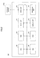
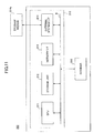
- FIG. 1 is a drawing illustrating an exemplary configuration of an inspection system 1010 according to a first embodiment.
- the inspection system 1010 includes a scanner 140 and an inspection apparatus 100 that are connected to each other via a data communication channel N (e.g., a network cable or a serial/parallel cable).
- a data communication channel N e.g., a network cable or a serial/parallel cable.
- the scanner 140 optically scans printed surfaces of printed materials to obtain scanned images.
- the inspection apparatus 100 is an information processing apparatus that inspects the print quality of printed materials.
- the inspection system 1010 provides the user with an inspection service for inspecting the print quality of printed materials.
- the user inputs a reference image of a printed surface of a printed material to the inspection apparatus 100.
- the reference image is obtained by ripping print data of the printed material and is used for print quality inspection.
- the user scans the printed surface of the printed material with the scanner 140 to obtain a scanned image.
- the scanner 140 sends the scanned image to the inspection apparatus 100.
- the inspection apparatus 100 compares the scanned image with the reference image to detect differences in pixel values between the scanned image and the reference image, performs a defect determining process based on the detected differences in pixel values and predetermined inspection thresholds (defect determining criteria), and outputs the results of the defect determining process (i.e., print quality inspection results) for the user.
- the inspection system 1010 of the first embodiment can provide an inspection service as described above.
- plural scanners 140 may be connected to one inspection apparatus 100. This configuration makes it possible to scan multiple printed materials at once with the scanners 140 and perform multiple defect determining processes in parallel by the inspection apparatus 100. This in turn makes it possible to efficiently inspect the print quality of a large number of printed materials in, for example, commercial printing.
- FIG. 2 is a block diagram illustrating an exemplary hardware configuration of the inspection apparatus 100.
- the inspection apparatus 100 may include an input unit 101, a display unit 102, a drive unit 103, a random access memory (RAM) 104, a read only memory (ROM) 105, a central processing unit (CPU) 106, an interface unit 107, and a hard disk drive (HDD) 108 that are connected to each other via a bus B.
- a bus B may be any type of bus
- the input unit 101 includes, for example, a keyboard and a mouse, and is used to input instructions (or operation signals) to the inspection apparatus 100.
- the display unit 102 displays, for example, processing results of the inspection apparatus 100.
- the interface unit 107 connects the inspection apparatus 100 to the data communication channel N.
- the inspection apparatus 100 can communicate with the scanner 140 and other apparatuses having a communication function via the interface unit 107.
- the HDD 108 is a non-volatile storage medium for storing various programs and data.
- the HDD 108 stores basic software (e.g., an operating system such as Windows (trademark/registered trademark) or UNIX (trademark/registered trademark)) for controlling the entire inspection apparatus 100, and applications that run on the basic software and provide various functions (e.g., an inspection function).
- the HDD 108 may manage the stored programs and data using a file system and/or a database (DB).
- DB database
- the drive unit 103 is an interface between the inspection apparatus 100 and a removable storage medium 103a.
- the inspection apparatus 100 can read and write data from and to the storage medium 103a via the drive unit 103.
- Examples of the storage medium 103a include a floppy (flexible) disk (FD), a compact disk (CD), a digital versatile disk (DVD), a secure digital (SD) memory card, and a universal serial bus (USB) memory.
- the ROM 105 is a non-volatile semiconductor memory (storage unit) that can retain data even when the power is turned off.
- the ROM 105 stores programs and data such as a basic input/output system (BIOS) that is executed when the inspection apparatus 100 is turned on, and system and network settings of the inspection apparatus 100.
- the RAM 104 is a volatile semiconductor memory (storage unit) for temporarily storing programs and data.
- the CPU 106 loads programs and data from storage units (e.g., the HDD 108 and the ROM 105) into the RAM 104 and executes the loaded programs to control the inspection apparatus 100 and to perform various functions.
- the inspection apparatus 100 can provide an inspection service (or an inspection function) of the first embodiment.
- the inspection apparatus 100 obtains a scanned image (hereafter called a target image) of a printed surface of a printed material and a reference image of the printed surface.
- the reference image is obtained by ripping print data of the printed material.
- the inspection apparatus 100 analyzes the reference image and obtains flatness levels indicating degrees of variation in pixel values in the reference image. Based on the obtained flatness levels, the inspection apparatus 100 identifies various types of image areas and determines inspection thresholds (defect determining criteria) for the respective types of image areas. Next, the inspection apparatus 100 compares pixels in the identified image areas of the reference image with pixels at the corresponding positions (in the corresponding image areas) in the target image to detect differences between their pixel values. Then, the inspection apparatus 100 determines whether the detected differences are greater than or equal to the corresponding inspection thresholds to detect defects on the printed surface.
- the inspection apparatus 100 of the first embodiment includes the inspection function as described above.
- FIG. 3 is a flowchart illustrating a related-art defect inspection process.
- a reference image and a target image are obtained (step S101). Based on the reference image, printed areas and/or non-printed areas in the printing range of a printed surface of a printed material are identified (step S102).
- step S103 For each of the identified areas, whether the identified area is a printed area or a non-printed area is determined.
- an image feature (density or light intensity) of the printed area of the reference image is compared with the image feature of the corresponding area of the target image to detect a difference in the image feature (step S104), and whether the detected difference is greater than or equal to a threshold 1 (for inspection of printed areas) is determined (step S105). If the difference is greater than or equal to the threshold 1, it is determined that there is a defect in the area of the target image.
- an image feature (density or light intensity) of the non-printed area of the reference image is compared with the image feature of the corresponding area of the target image to detect a difference in the image feature (step S106), and whether the detected difference is greater than or equal to a threshold 2 (for inspection of non-printed areas) is determined (step S107). If the difference is greater than or equal to the threshold 2, it is determined that there is a defect in the area of the target image.
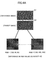
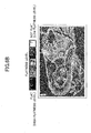
- FIGs. 4A and 4B are drawings illustrating differences in pixel values in printed areas.
- printed areas may be roughly categorized into two types: a non-flat area (e.g., a picture area or an edge area) where the degree of variation in pixel values is large ( FIG. 4A ) and a flat area (e.g., a background area) where the degree of variation in pixel values is small ( FIG. 4B ).
- a non-flat area e.g., a picture area or an edge area
- a flat area e.g., a background area
- the pixel values (e.g., RGB values) of a pixel in a picture area (a non-flat area) of a reference image G1 are compared with the pixel values of a pixel at the corresponding position in a target image G2 to detect differences in the pixel values.
- each of the differences in the pixel values between the reference image G1 and the target image G2 is about 10.
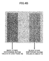
- FIG. 4B illustrates a background area (a flat area) where a white stripe and a black stripe (i.e., defects) are generated.
- a white stripe and a black stripe i.e., defects
- FIGs. 4A and 4B unlike in a non-flat area, even small deviations in pixel values in a flat area are easily noticeable to the human eye and may affect the print quality. In other words, the human eye is insensitive to small deviations in pixel values in a non-flat area and sensitive to small deviations in pixel values in a flat area.
- the difference in pixel values between the reference image G1 and the target image G2 is less than 10 in an area corresponding to the white stripe and is about 5 in an area corresponding to the black stripe.
- the inspection apparatus 100 analyzes the reference image G1 (obtained by ripping print data) to obtain flatness levels indicating degrees of variation in pixel values, identifies various types of image areas based on the obtained flatness levels, and determines inspection thresholds (defect determining criteria) used in the defect determining process for the respective types of image areas.
- the inspection apparatus 100 inspects the print quality of flat areas using a defect determining criterion that is stricter than that used for the inspection of non-flat areas. This configuration makes it possible to accurately inspect the print quality of printed areas.
- FIG. 5 is a block diagram illustrating an exemplary functional configuration of the inspection apparatus 100 according to the first embodiment.
- the inspection apparatus 100 includes an image obtaining unit 11, a flatness analysis unit 12, and an inspection control unit 13.
- the image obtaining unit 11 is a functional unit that obtains the reference image G1 and the target image G2. For example, the image obtaining unit 11 receives the reference image G1 that is obtained by ripping print data and input to the inspection apparatus 100, and receives the target image G2 that is a scanned image of a printed surface from the scanner 140.
- the flatness analysis unit 12 is a functional unit that analyzes the reference image G1 received from the image obtaining unit 11 and thereby obtains flatness levels indicating degrees of variation in pixel values of the reference image G1. For example, the flatness analysis unit 12 may calculate a standard deviation or a variance of pixel values (RGB values) in each rectangular area (e.g., 5 x 5, 7 x 7, or 9 x 9) of the reference image G1 as a direct flatness level. As another example, the flatness analysis unit 12 may calculate a total or an average of differences between pixel values (RGB values) of a reference pixel and adjacent pixels adjacent to the reference pixel in each rectangular area of the reference image G1 as a direct flatness level. The flatness analysis unit 12 may also be configured to convert or quantize the degrees of variation in pixel values (RGB values) calculated as described above into representative values indicating flatness levels.
- RGB values degrees of variation in pixel values
- the reference image G1 obtained by ripping print data and having stable pixel values is used to obtain the flatness levels.
- pixel values are represented by RGB values.
- pixel values may be represented by any other color space values.
- FIGs. 6A and 6B are drawings used to describe an exemplary relationship between types of image areas and flatness levels.
- FIG. 6A illustrates types of image areas in the reference image G1.
- the reference image G1 includes printed areas and a non-printed area.
- the printed areas are covered by toner or ink. Meanwhile, the non-printed area is not covered by toner or ink. In the descriptions below, the non-printed area is called a blank area.
- the printed areas include a background area, an edge area, and a picture area.
- the background area is a flat area where the degree of variation in pixel values is small.
- the edge area and the picture area are non-flat areas where the degree of variation in pixel values is large.
- FIG. 6B illustrates analysis results of the reference image G1 illustrated in FIG. 6A .
- the analysis results of the reference image G1 are represented by eight flatness levels.
- the degrees of variation in pixel values in the reference image G1 are converted by the flatness analysis unit 12 into representative values 0 through 7.
- the flatness level "0" is assigned to a pixel whose degree of variation in pixel values is the smallest
- the flatness level "7" is assigned to a pixel whose degree of variation in pixel values is the largest.
- the flatness levels "1" through “6” are assigned to pixels whose degrees of variation in pixel values are between the largest and the smallest.
- the inspection apparatus 100 Based on the eight flatness levels, the inspection apparatus 100 identifies printed areas such as a background area, an edge area, and a picture area in the reference image G1. For example, the background area where the degree of variation in pixel values is the smallest may be identified based on the flatness level "0". The picture area where the degree of variation in pixel values is greater than that in the background area and is smaller than that in the edge area may be identified based on the flatness levels "1" through "6". The edge area where the degree of variation in pixel values is the largest may be identified based on the flatness level "7".
- the blank area may be identified based on the flatness level "0". Also, since the blank area is a non-printed area, it may be identified based on other information such as the paper color or print data. For example, RGB values obtained by scanning blank paper with the scanner 140 may be stored in a storage area (e.g., the RAM 104) of the inspection apparatus 100 and an area in the reference image G1 corresponding to the stored RGB values may be identified as the blank area. Also, the blank area may be identified based on margin settings in print data or based on pixel values corresponding to the white color (RGB values: 255, 255, 255) in the reference image G1.
- the inspection control unit 13 is a functional unit that controls the inspection process for various types of image areas based on the flatness levels. More specifically, the inspection control unit 13 controls a process of determining inspection thresholds (defect determining criteria) for different types of image areas, a process of comparing the reference image G1 and the target image G2 to detect differences in pixel values, and a process of detecting defects in a printed surface based on the detected differences and the inspection thresholds.
- the inspection control unit 13 includes an area identifying unit (threshold determining unit) 131, a difference detecting unit 132, and a determining unit (defect detecting unit) 133.
- the area identifying unit (threshold determining unit) 131 is a functional unit that identifies various types of image areas in the reference image G1 based on the analysis results (calculated flatness levels) of the flatness analysis unit 12.
- the area identifying unit 131 identifies, for example, a background area, an edge area, and a picture area based on the flatness levels.
- the area identifying unit 131 determines inspection thresholds (defect determining criteria) for the identified image areas. As described above, to accurately inspect printed areas, it is preferable to use different thresholds for flat areas (where the degree of variation in pixel values is small) and non-flat areas (where the degree of variation in pixel values is large). Therefore, the area identifying unit 131 assigns different (gradual) inspection thresholds (preset values such as 45, 30, 15, and 4) to the respective types of identified image areas. The inspection thresholds may be predetermined for the respective types of image areas. For example, the area identifying unit 131 determines inspection thresholds as described below.
- the area identifying unit 131 determines an inspection threshold (e.g., the smallest threshold "4") that is smaller than the inspection thresholds used for other image areas (e.g., the blank area, the picture area, and the edge area).
- an inspection threshold e.g., the smallest threshold "4"
- the area identifying unit 131 determines an inspection threshold (e.g., the largest threshold "45") that is greater than the inspection thresholds used for other printed areas (e.g., the background area and the picture area).
- the area identifying unit 131 determines an inspection threshold (e.g., the threshold "15") that is between the inspection thresholds used for other printed areas (e.g., the background area and the edge area).
- an inspection threshold e.g., the threshold "15”
- the non-printed area or the blank area has the highest flatness level (indicated by the smallest value) among the image areas.
- a smear on the paper surface is considered to be a defect. Therefore, in the blank area, a relatively large difference in pixel values between a pixel representing the smear in the target image G2 and the corresponding pixel in the reference image G1 needs to be detected. For this reason, for the blank area, the area identifying unit 131 determines an inspection threshold (e.g., the threshold "30”) that comes between the inspection threshold for the picture area and the inspection threshold for the edge area.
- an inspection threshold e.g., the threshold "30
- the inspection control unit 13 determines types of image areas (e.g., the blank area, the background area, the picture area, and the edge area) based on the flatness levels indicating degrees of variation in pixel values and uses different inspection thresholds (defect determining criteria) for the respective types of image areas. In other words, the inspection control unit 13 changes the sensitivity levels for detecting defects based on the flatness levels of image areas of the reference image G1.
- the difference detecting unit 132 is a functional unit that compares the reference image G1 and the target image G2 and thereby detects differences in pixel values.
- the difference detecting unit 132 compares pixels in each identified image area of the reference image G1 with pixels at the corresponding positions in the target image G2 to detect differences between their pixel values. Exemplary methods of detecting differences in pixel values are described below;
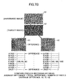
- FIGs. 7A and 7B are drawings illustrating exemplary methods of detecting differences in pixel values according to the first embodiment.
- FIG. 7A illustrates a first difference detection method where differences between pixels are detected
- FIG. 7B illustrates a second difference detection method where an average of differences between pixels in each rectangular area is detected.
- pixel values (RGB values) of each pixel in the reference image G1 are compared with pixel values of the corresponding pixel in the target image G2 to obtain absolute values indicating the differences in pixel values (for the respective RGB components) between the pixels.
- pixel values (RGB values) of pixels in a rectangular area R1 of the reference image G1 are compared with pixel values of pixels in a corresponding rectangular area R2 (the rectangular areas R1 and R2 may be called a rectangular area(s) R when distinction is not necessary) of the target image G2 to obtain absolute values indicating the differences between the pixel values (for the respective RGB components).
- pixels A through I in the rectangular area R1 of 3 x 3 pixels i.e., 9 pixels
- pixels A through I in the rectangular area R2 of 3 x 3 pixels are compared with pixels A through I in the rectangular area R2 of 3 x 3 pixels to calculate nine sets of differences.
- the nine sets of differences are totaled to obtain total differences (for the respective RGB components), and the respective total differences are divided by the number of pixels (in this example, "9") in the rectangular area R to obtain average differences in pixel values in the rectangular area R.
- the size (filter size) of the rectangular area R may be determined depending on the type of defects to be detected: For example, to detect white or black stripes generated in the background area, the size of the rectangular area R may be set at 3x3, 3x7, or 7x3 depending on the characteristics of the white or black stripes.
- the size of the rectangular area R used in the second difference detection method may be determined for each of identified image areas.
- the inspection control unit 13 detects differences in pixel values between the reference image G1 and the target image G2 according to the difference detection methods as described above.
- the determining unit (defect detecting unit) 133 is a functional unit that performs a defect determining process.
- the determining unit 133 determines whether the differences detected by the difference detecting unit 132 are greater than or equal to the inspection thresholds determined for the respective types of image areas by the area identifying unit 131 and based on the results, determines whether defects are present on the printed surface. For example, when the differences in an image area are greater than or equal to the corresponding inspection threshold, the determining unit 133 determines that there is a defect (or an error) in the image area of the target image G2.
- the inspection control unit 13 performs the defect determining process for each of the identified image areas and thereby inspects the printed surface.
- the inspection function of the first embodiment is provided through collaboration among the above described functional units.
- the functional units are implemented by executing software programs installed in the inspection apparatus 100.
- the software programs are loaded by a processing unit (e.g., the CPU 106) from storage units (e.g., the HDD 108 and/or the ROM 105) into a memory (e.g., the RAM 104) and are executed to implement the functional units of the inspection apparatus 100.
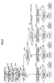
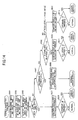
- FIG. 8 is a flowchart illustrating an exemplary defect inspection process according to the first embodiment.
- the image obtaining unit 11 of the inspection apparatus 100 obtains the reference image G1 and the target image G2 (step S201). In this step, the image obtaining unit 11 receives the reference image G1 input to the inspection apparatus 100 and receives the target image G2 from the scanner 140.
- the flatness analysis unit 12 analyzes the reference image G1 to obtain flatness levels of the reference image G1 (step S202). For example, the flatness analysis unit 12 receives the reference image G1 from the image obtaining unit 11 and obtains direct flatness levels by calculating a standard deviation or a variance of pixel values (RGB values) in each rectangular area R of the reference image G1 or by calculating a total or an average of differences between pixel values (RGB values) of a reference pixel and adjacent pixels adjacent to the reference pixel in each rectangular area R of the reference image G1.
- RGB values standard deviation or a variance of pixel values
- the inspection control unit 13 controls the inspection process for respective types of image areas based on the flatness levels.
- the area identifying unit 131 of the inspection control unit 13 identifies printed areas and a non-printed area in the reference image G1 based on the flatness levels received from the flatness analysis unit 12 (step S203). For example, the area identifying unit 131 identifies a blank area based on the paper color or print data, and identifies a background area, a picture area, and an edge area based on the flatness levels. In this exemplary process, it is assumed that eight flatness levels (a higher flatness level indicates lower flatness) are provided, the flatness level "0" corresponds to the background area, the flatness level "1" through “6" correspond to the picture area, and the flatness level "7" corresponds to the edge area.
- the area identifying unit 131 assigns predetermined (gradual) inspection thresholds (preset values) A through D (D > A > C > B) to the respective types of image areas.
- predetermined (gradual) inspection thresholds (preset values) A through D (D > A > C > B) to the respective types of image areas.
- the largest threshold D is assigned to the edge area
- the smallest threshold B is assigned to the background area
- the threshold A that is greater than the threshold C and smaller than the threshold D is assigned to the blank area
- the threshold C that is greater than the threshold B and smaller than the threshold A is assigned to the picture area.
- the difference detecting unit 132 of the inspection control unit 13 performs a defect determining process for each type of image area identified by the area identifying unit 131.
- the difference detecting unit 132 compares pixels of the reference image G1 and the target image G2 according to the first difference detection method described above to detect differences in pixel values (step S205). In this step, the difference detecting unit 132 compares pixel values (RGB values) of each pixel in the reference image G1 with pixel values of the corresponding pixel in the target image G2 to obtain absolute values indicating the differences between the pixel values (for the respective RGB components).
- the determining unit 133 of the inspection control unit 13 determines whether the differences detected by the difference detecting unit 132 are greater than or equal to the threshold A assigned to the blank area (the defect determining criterion for the blank area) (step S206). If the differences are greater than or equal to the threshold A (YES in step S206), the determining unit 133 determines that there is a defect (or an error) in the blank area of the target image G2.
- the inspection control unit 13 performs the defect determining process for the blank area using the threshold A that is between the thresholds D and C assigned to the edge area and the picture area.
- the difference detecting unit 132 compares pixels of the reference image G1 and the target image G2 according to the first difference detection method described above to detect differences in pixel values (step S208).
- the determining unit 133 determines whether the differences detected by the difference detecting unit 132 are greater than or equal to the threshold B assigned to the background area (the defect determining criterion for the background area) (step S209). If the differences are greater than or equal to the threshold B (YES in step S209), the determining unit 133 determines that there is a defect (or an error) in the background area of the target image G2.
- the inspection control unit 13 Since it is necessary to detect even small deviations in pixel values in the background area, the inspection control unit 13 performs the defect determining process for the background area using the threshold B that is the smallest threshold among the thresholds assigned to the image areas.
- the difference detecting unit 132 compares pixels of the reference image G1 and the target image G2 according to the first difference detection method described above to detect differences in pixel values (step S211).
- the determining unit 133 determines whether the differences detected by the difference detecting unit 132 are greater than or equal to the threshold C assigned to the picture area (the defect determining criterion for the picture area) (step S212). If the differences are greater than or equal to the threshold C (YES in step S212), the determining unit 133 determines that there is a defect (or an error) in the picture area of the target image G2.
- the inspection control unit 13 Since the degree of variation in pixel values in the picture area is greater than that in the background area and less than that in the edge area, the inspection control unit 13 performs the defect determining process for the picture area using the threshold C that is between the thresholds A and B assigned to the blank area and the background area.
- the difference detecting unit 132 compares pixels of the reference image G1 and the target image G2 according to the first difference detection method described above to detect differences in pixel values (step S213).
- the determining unit 133 determines whether the differences detected by the difference detecting unit 132 are greater than or equal to the threshold D assigned to the edge area (the defect determining criterion for the edge area) (step S214). If the differences are greater than or equal to the threshold D (YES in step S214), the determining unit 133 determines that there is a defect (or an error) in the edge area of the target image G2.
- the inspection control unit 13 Since it is not necessary to detect small deviations in pixel values in the edge area, the inspection control unit 13 performs the defect determining process for the edge area using the threshold D that is the largest threshold among the thresholds assigned to the image areas.
- the inspection apparatus 100 of the first embodiment analyzes the reference image G1 to obtain flatness levels indicating degrees of variation in pixel values, identifies various types of image areas based on the obtained flatness levels, and determines inspection thresholds (defect determining criteria) used in the defect determining process for the respective types of image areas.
- This configuration makes it possible to prevent excessive defect detection (detection error) in a non-flat area where the degree of variation in pixel values is large and to strictly detect defects in a flat area where the degree of variation in pixel values is small.
- the second difference detection method may be used instead of the first difference detection method.
- the difference detecting unit 132 compares pixels in the corresponding rectangular areas R of the reference image G1 and the target image G2 and calculates average differences between the pixels. More specifically, the difference detecting unit 132 compares pixel values (RGB values) of pixels in a rectangular area R of the reference image G1 with pixel values of pixels in the corresponding rectangular area R of the target image G2 to obtain absolute values indicating the differences between the pixel values (for the respective RGB components). Next, the difference detecting unit 132 totals the differences to obtain total differences for the respective RGB components, and divides the respective total differences by the number of pixels in the rectangular area R to obtain average differences between the pixels.
- RGB values pixel values
- the determining unit 133 detects defects based on the average differences and the inspection thresholds (defect determining criteria).
- the second difference detection method makes it possible to more accurately detect differences.
- the difference detection unit 132 may be configured to use one of the first and second difference detection methods depending on the type of image area.
- the difference detection unit 132 may be configured to use the first difference detection method for the picture area and the edge area and to use the second difference detection method for the background area to more accurately detect differences in pixel values.
- the difference detection unit 132 may be configured to operate according to one of the first and second difference detection methods depending on the type of image area (or depending on whether the flatness level of the image area is higher than a predetermined level).
- steps S305, S308, S311, and S313 of FIG. 9 that are different from the corresponding steps in FIG. 8 are mainly described.
- the difference detecting unit 132 compares pixels of the reference image G1 and the target image G2 according to the first difference detection method to detect differences in pixel values (step S305).
- the inspection control unit 13 detects differences in pixel values using the first difference detection method that is less accurate than the second difference detection method.
- the difference detecting unit 132 compares pixels in the corresponding rectangular areas R of the reference image G1 and the target image G2 according to the second difference detection method to detect average differences in pixel values (step S308).
- the inspection control unit 13 detects differences in pixel values using the second difference detection method that is more accurate than the first difference detection method.
- the difference detecting unit 132 compares pixels of the reference image G1 and the target image G2 according to the first difference detection method to detect differences in pixel values (step S311).
- the inspection control unit 13 detects differences in pixel values using the first difference detection method that is less accurate than the second difference detection method.
- the difference detecting unit 132 compares pixels of the reference image G1 and the target image G2 according to the first difference detection method to detect differences in pixel values (step S313).
- the inspection control unit 13 detects differences in pixel values using the first difference detection method that is less accurate than the second difference detection method.
- the inspection apparatus 100 may be configured to use different inspection thresholds (defect determining criteria) and different difference detection methods depending on the types (or flatness levels) of image areas. This configuration makes it possible to accurately inspect the print quality of image areas.
- the inspection apparatus 100 may include a function (hereafter called a defect-type determining function) for determining the type of a detected defect.
- the defect-type determining function may be provided by the determining unit 133 or by a separate functional unit of the inspection apparatus 100 (i.e., a defect-type determining unit).
- the defect-type determining function determines the type of a defect based on difference data of an image area.
- the defect-type determining function may use different methods depending on the types of defects to be determined. Therefore, in the descriptions below, it is assumed that a white/black stripe generated in the background area is to be determined.
- FIG. 10 is a flowchart illustrating an exemplary defect inspection process where the type of a defect is also determined. Below, step S415 of FIG. 10 that is added to the defect inspection process of FIG. 9 is mainly described.
- the inspection apparatus 100 determines whether a detected defect is a white/black stripe based on difference data of the image area (step S415).
- Step S415 is described in more detail below.
- the inspection apparatus 100 performs a labeling process on the target image G2 based on difference data (differences greater than or equal to the corresponding inspection threshold) of the image area.
- the labeling process indicates a process of attaching the same label to connected pixels (e.g., a group of eight pixels) and thereby dividing the target image G2 into multiple image areas (or groups).
- the inspection apparatus 100 identifies a circumscribing rectangular image area corresponding to the detected defect in the target image G2.
- the inspection apparatus 100 determines whether the width, the length, and the aspect ratio of the identified circumscribing rectangular image area are greater than or equal to thresholds (defect-type determining criteria) indicating the predetermined width, length, and aspect ratio.
- the thresholds (defect-type determining criteria) may be determined for each type of defect to be determined.
- the inspection apparatus 100 determines that the detected defect in the target image G2 is a white/black stripe.
- the inspection apparatus 100 may be configured to calculate an adjacent distance between the circumscribing rectangular image areas based on the coordinates (in the coordinate space of the target image G2) of pixels constituting the circumscribing rectangular image areas, and to combine the circumscribing rectangular image areas if the adjacent distance is less than a predetermined adjacent distance threshold.
- the inspection apparatus 100 may be configured to determine the density of defects based on the width(s), the length(s), and the number of the combined circumscribing rectangular image areas and to determine the type of the defect based on the determined density.
- the inspection apparatus 100 is used as an example of an apparatus that provides the inspection function.
- the first embodiment may be applied to any other type of apparatus.
- the first embodiment may be applied to an image processing apparatus 200 as illustrated in FIG. 11 .
- FIG. 11 is a block diagram illustrating an exemplary hardware configuration of the image processing apparatus 200 that provides the inspection function.
- the image processing apparatus 200 may include a controller 210 and a scanner 240 that are connected to each other via a bus B.
- the scanner 240 optically scans a printed material or a document and generates image data (a scanned image).
- the controller 210 is a control circuit board including a CPU 211, a storage unit 212, a network I/F 213, and an external storage I/F 214 that are connected via the bus B.
- the storage unit 212 includes a RAM, a ROM, and an HDD for storing various programs and data.
- the CPU 211 loads programs and data from the ROM and/or the HDD into the RAM and executes the loaded programs to control the image processing apparatus 200 and thereby implement various functions.
- the inspection function of the first embodiment may be implemented by loading a program into the RAM and executing the loaded program by the CPU 211.
- the network I/F 213 is an interface for connecting the image processing apparatus 200 to a data communication channel.
- the image processing apparatus 200 can communicate with other apparatuses having communication functions via the network I/F 213.
- the external storage I/F 214 is an interface between the image processing apparatus 200 and a storage medium 214a used as an external storage. Examples of the storage medium 214a include an SD memory card, a USB memory, a CD, and a DVD.
- the image processing apparatus 200 can read and write data from and to the storage medium 214a via the external storage I/F 214.
- the image processing apparatus 200 can single-handedly provide an inspection service for inspecting the print quality of printed materials.
- the first embodiment may also be applied to an image forming apparatus such as a multifunction peripheral (MFP).
- MFP multifunction peripheral
- FIG. 12 is a block diagram illustrating an exemplary hardware configuration of an image forming apparatus 300 that provides the inspection function.
- the image forming apparatus 300 may include a controller 310, an operations panel 320, a plotter 330, and a scanner 340 that are connected to each other via a bus B.
- the operations panel 320 includes a display unit for providing information such as device information to the user and an input unit for receiving user inputs such as settings and instructions.
- the plotter 330 includes an image forming unit for forming an image on a recording medium (e.g., paper). For example, the plotter 330 forms an image by electrophotography or inkjet printing.
- the controller 310 is a control circuit board including a CPU 311, a storage unit 312, a network I/F 313, and an external storage I/F 314 that are connected via the bus B.
- the storage unit 312 includes a RAM, a ROM, and an HDD for storing various programs and data.
- the CPU 311 loads programs and data from the ROM and/or the HDD into the RAM and executes the loaded programs to control the image forming apparatus 300 and thereby implement various functions.
- the inspection function of the first embodiment may be implemented by loading a program into the RAM and executing the loaded program by the CPU 311.
- the network I/F 313 is an interface for connecting the image forming apparatus 300 to a data communication channel.
- the image forming apparatus 300 can communicate with other apparatuses having communication functions via the network I/F 313.
- the external storage I/F 314 is an interface between the image forming apparatus 200 and a storage medium 314a used as an external storage. Examples of the storage medium 314a include an SD memory card, a USB memory, a CD, and a DVD.
- the image forming apparatus 300 can read and write data from and to the storage medium 314a via the external storage I/F 314.
- the image forming apparatus 300 can single-handedly provide an inspection service for inspecting the print quality of printed materials.
- the scanner 140 and the inspection apparatus 100 are connected to each other.
- the configuration of the inspection system 1010 is not limited to that described above.
- the inspection system 1010 may include the inspection apparatus 100 and the image processing apparatus 200 or the image forming apparatus 300 that are connected to each other.
- the target image G2 is sent from the image processing apparatus 200 or the image forming apparatus 300 to the inspection apparatus 100.
- the image obtaining unit 11 of the inspection apparatus 100 obtains the reference image G1 and the target image G2.
- the flatness analysis unit 12 analyzes the reference image G1 and thereby obtains flatness levels indicating degrees of variation in pixel values in the reference image G1.
- the inspection control unit 13 Based on the obtained flatness levels, the inspection control unit 13 identifies various types of image areas in the reference image G1 and determines inspection thresholds (defect determining criteria) for the respective types of image areas. Next, the inspection control unit 13 compares pixels in each identified image area of the reference image G1 with pixels at the corresponding positions in the target image G2 to detect differences between their pixel values. Then, the inspection control unit 13 determines whether the detected differences are greater than or equal to the corresponding inspection thresholds to detect defects on the printed surface.
- inspection thresholds defect determining criteria
- the inspection apparatus 100 of the first embodiment inspects the print quality of flat areas using a defect determining criterion that is stricter (or more sensitive) than that used for the inspection of non-flat areas. This configuration makes it possible to accurately inspect the print quality of image areas.
- a second embodiment is different from the first embodiment in that when the background area is identified, an inspection threshold (defect determining criterion) used to detect a defect in the background area is determined based on a flatness level obtained by analyzing the target image G2.
- an inspection threshold defect determining criterion
- FIG. 13 is a block diagram illustrating an exemplary functional configuration of the inspection apparatus 100 according to the second embodiment.
- the flatness analysis unit 12 also analyzes the target image G2 in addition to the reference image G1 and thereby obtains flatness levels indicating degrees of variation in pixel values in the target image G2.
- the method(s) used to analyze the reference image G1 in the first embodiment may be used to analyze the target image G2. Accordingly, in the second embodiment, the flatness analysis unit 12 analyzes the reference image G1 and the target image G2 and thereby obtains two sets of flatness levels for the reference image G1 and the target image G2.
- the area identifying unit 131 Based on the obtained flatness levels for the reference image G1, the area identifying unit 131 identifies various types of image areas in the reference image G1 and determines inspection thresholds (defect determining criteria) for the respective types of image areas.
- the area identifying unit 131 determines an inspection threshold (defect determining criterion) for the background area as described below.
- the area identifying unit 131 refers to a flatness level(s) (in the obtained flatness levels) of an image area of the target image G2 that is located at a position corresponding to the identified background area of the reference image G1.
- a flatness level(s) in the obtained flatness levels
- the area identifying unit 131 determines whether the corresponding image area of the target image G2 is flat. For example, the area identifying unit 131 determines whether the flatness level of the corresponding image area of the target image G2 is greater than or equal to a predetermined flatness threshold (e.g, "2").
- a predetermined flatness threshold e.g, "2"
- the area identifying unit 131 assumes that there is a defect in the image area of the target image G2 and determines a first inspection threshold (defect determining criterion) (e.g., "4") that enables detecting small deviations in pixel values for the background area (or the image area corresponding to the background area).
- a first inspection threshold defect determining criterion
- the area identifying unit 131 assumes that there is no defect in the image area of the target image G2 and determines a second inspection threshold (defect determining criterion) (e.g., "10") that is greater than the first inspection threshold for the background area (or the image area corresponding to the background area).
- a second inspection threshold defect determining criterion
- the inspection control unit 13 performs the difference detecting step and the defect determining step at different accuracy levels in a case where the image area of the target image G2 is flat and a case where the image area of the target image G2 is not flat.
- the difference detecting unit 132 detects average differences between pixels in rectangular areas R of the reference image G1 and the target image G2 according to the second difference detection method described in the first embodiment. Then, the determining unit 133 determines whether the detected differences are greater than or equal to the first inspection threshold to detect a defect in the background area.
- the size of the rectangular areas R may be set at 3x7 or 7x3 used to detect a white/black stripe in the background area.
- the difference detecting unit 132 detects differences between pixels in the reference image G1 and the target image G2 according to the first difference detection method described in the first embodiment. Then, the determining unit 133 determines whether the detected differences are greater than or equal to the second inspection threshold to detect a defect in the background area.
- the inspection apparatus 100 determines the probability that a defect is present in a flat area based on a flatness level obtained by analyzing the target image G2 and if it is probable that a defect is present, inspects the print quality of the flat area using a strict (or sensitive) defect determining criterion. This configuration makes it possible to efficiently and accurately inspect the print quality of image areas.
- the inspection function of the second embodiment is provided through collaboration among the functional units.
- the functional units are implemented by executing software programs installed in the inspection apparatus 100.
- the software programs are loaded by a processing unit (e.g., the CPU 106) from storage units (e.g., the HDD 108 and/or the ROM 105) into a memory (e.g., the RAM 104) and are executed to implement the functional units of the inspection apparatus 100.
- the second embodiment may also be applied to the image processing apparatus 200 of FIG. 11 and the image forming apparatus 300 of FIG. 12 .
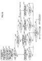
- FIG. 14 is a flowchart illustrating an exemplary defect inspection process according to the second embodiment. Below, steps S502 and S508 of FIG. 14 that are different from the corresponding steps in FIG. 8 are mainly described.
- the image obtaining unit 11 of the inspection apparatus 100 obtains the reference image G1 and the target image G2 (step S501).
- the flatness analysis unit 12 analyzes the reference image G1 and the target image G2 and thereby obtains their flatness levels (step S502).
- the flatness analysis unit 12 adjusts the coordinate spaces of the reference image G1 and the target image G2 to correlate the analysis results of the reference image G1 and the target image G2.
- the flatness analysis unit 12 sends the obtained analysis results (flatness levels) to the inspection control unit 13.
- the inspection control unit 13 controls the defect inspection process for respective types of image areas based on the flatness levels of the reference image G1.
- the area identifying unit 131 performs a defect determining process as illustrated in FIG. 15 (step S508).
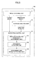
- FIG. 15 is a flowchart illustrating an exemplary defect determining process for a background area according to the second embodiment.
- the area identifying unit 131 of the inspection control unit 13 determines whether an image area of the target image G2 corresponding to the background area of the reference image G1 is flat based on the obtained flatness levels (analysis results) of the target image G2 (step S601). In this step, the area identifying unit 131 refers to a flatness level(s) (in the obtained flatness levels) of the image area of the target image G2 and determines whether the flatness level is greater than or equal to a predetermined flatness threshold.
- the area identifying unit 131 assumes that there is no defect in the image area of the target image G2 and the difference detecting unit 132 detects differences between pixels in the reference image G1 and the target image G2 according to the first difference detection method (step S602).
- the determining unit 133 determines whether the differences detected by the difference detecting unit 132 are greater than or equal to an inspection threshold B1 (step S603).
- the inspection threshold B1 corresponds to the second inspection threshold (defect determining criterion) described above and is greater than an inspection threshold B2 that corresponds to the first inspection threshold and is used when the flatness level is greater than or equal to the flatness threshold.
- the determining unit 133 determines that there is a defect (or an error) in the image area of the target image G2.
- the area identifying unit 131 assumes that there is a defect in the image area of the target image G2 and the difference detecting unit 132 detects average differences between pixels in rectangular areas R of the reference image G1 and the target image G2 according to the second difference detection method (step S604).
- the determining unit 133 determines whether the differences detected by the difference detecting unit 132 are greater than or equal to the inspection threshold B2 (step S605).
- the inspection threshold B2 (first inspection threshold) is set at a value less than the inspection threshold B1 so that small deviations in pixel values can be detected.
- the determining unit 133 determines that there is a defect (or an error) in the image area of the target image G2.
- the image obtaining unit 11 of the inspection apparatus 100 obtains the reference image G1 and the target image G2.
- the flatness analysis unit 12 analyzes the reference image G1 and the target image G2 to obtain flatness levels indicating degrees of variation in pixel values in the reference image G1 and the target image G2.
- the inspection control unit 13 Based on the obtained flatness levels of the reference image G1, the inspection control unit 13 identifies various types of image areas in the reference image G1 and determines inspection thresholds (defect determining criteria) for the respective types of image areas.
- the inspection control unit 13 When a flat area where the degree of variation in pixel values is small is identified in the reference image G1, the inspection control unit 13 refers to a flatness level(s) (in the obtained flatness levels) of an image area of the target image G2 that corresponds to the identified flat area of the reference image G1. Next, based on the flatness level, the inspection control unit 13 determines the probability that a defect is present in the image area of the target image G2 and if it is probable that a defect is present, determines a strict (or sensitive) threshold (defect determining criterion) for the image area of the target image G2.
- a strict (or sensitive) threshold defect determining criterion
- the inspection control unit 13 compares pixels in the flat area of the reference image G1 with pixels in the corresponding image area of the target image G2 to detect differences between their pixel values. Then, the inspection control unit 13 determines whether the detected differences are greater than or equal to the "strict" threshold to detect defects in the image area of the target image G2.
- the inspection apparatus 100 of the second embodiment provides advantageous effects similar to those of the first embodiment and also makes it possible to efficiently inspect the print quality of a flat area where the degree of variation in pixel values is small.
- the inspection functions of the above embodiments are implemented, for example, by executing a program(s), which is written in a programming language supported by the operating environment (platform) of the inspection apparatus 100 (the image processing apparatus 200 or the image forming apparatus 300), using a processing unit of the inspection apparatus 100 (the image processing apparatus 200 or the image forming apparatus 300).
- such a program may be stored in a non-transitory computer-readable storage medium (e.g., the storage medium 103a/214a/314a) such as a floppy (flexible) disk (FD), a compact disk (CD), a digital versatile disk (DVD), a secure digital (SD) memory card, and a universal serial bus (USB) memory.
- the program stored in the storage medium may be installed in the inspection apparatus 100 (the image processing apparatus 200 or the image forming apparatus 300) via the drive unit 103 (or the external storage I/F 214/314).
- the program may be installed via a telecommunication line and the interface unit 107 (or the network I/F 213/313) into the inspection apparatus 100 (the image processing apparatus 200 or the image forming apparatus 300).
- the degrees of variation in pixel values are represented by eight flatness levels. However, any number of flatness levels may be used depending on the desired inspection accuracy.
- printed areas including the background area, the picture area, and the edge area and a non-printed area including the blank area are identified based on the flatness levels.
- the types of image areas to be identified are not limited to those described above. Any number of types of image areas may be defined in association with flatness levels.
- the inspection apparatus 100 may include an image processor(s) (e.g., an application specific integrated circuit (ASIC)) and multiple difference detection processes for different types of image areas may be executed in parallel.
- image processor(s) e.g., an application specific integrated circuit (ASIC)
- ASIC application specific integrated circuit
- differences in pixel values detected for the respective types of image areas may be temporarily stored in a storage area and may be referred to in a defect determining process(es) to be performed later by a CPU.
- both the reference image G1 and the target image G2 are analyzed to obtain flatness levels.
- the flatness levels of the target image G2 may be obtained only when a background area is detected based on the flatness levels of the reference image G1.
- An aspect of this disclosure provides an inspection apparatus, an inspection method, and a non-transitory storage medium storing program code for causing the inspection apparatus to perform the inspection method.
Landscapes
- Engineering & Computer Science (AREA)
- Quality & Reliability (AREA)
- Investigating Materials By The Use Of Optical Means Adapted For Particular Applications (AREA)
- Image Analysis (AREA)
- Image Processing (AREA)
Claims (15)
- Inspektionsvorrichtung, Folgendes umfassend:eine Empfangseinheit, zum Empfangen eines Zielbildes (G2) konfiguriert, das durch Scannen einer bedruckten Oberfläche eines bedruckten Materials erhalten wird, und zum Empfangen eines Referenzbildes (G1), das aus Druckdaten der bedruckten Oberfläche erhalten wird;gekennzeichnet durch eine Analyseeinheit (12), konfiguriert zum Analysieren des Referenzbildes (G1), um Ebenheitsniveaus zu erhalten, die Variationsgrade in Pixelwerten anzeigen; undeine Steuereinheit (13) konfiguriert zum
Bestimmen von Inspektionsschwellen (4, 15, 30, 45) für verschiedene Typen von Bildbereichen im Referenzbild (G1) auf der Basis der Ebenheitsniveaus.
Vergleichen des Referenzbildes (G1) mit dem Zielbild (G2), um Differenzen in Pixelwerten zu detektieren, und
Bestimmen, ob die Differenzen größer oder gleich den Inspektionsschwellen sind, um die Druckqualität der bedruckten Oberfläche für die jeweiligen Bildbereiche zu inspizieren. - Inspektionsvorrichtung nach Anspruch 1, worin die Steuereinheit (13) konfiguriert ist zum
Identifizieren der verschiedenen Typen von Bildbereichen im Referenzbild (G1) auf der Basis der Ebenheitsniveaus; und
Zuweisen von voreingestellten Werten an die verschiedenen Typen von Bildbereichen als die Inspektionsschwellen. - Inspektionsvorrichtung nach Anspruch 2, worin
die Bildbereiche bedruckte Bereiche einschließen, wo Information gedruckt ist, und nichtbedruckte Bereiche, wo keine Information gedruckt ist;
ein höheres Ebenheitsniveau der Ebenheitsniveaus einen niedrigeren Variationsgrad in Pixelwerten anzeigt und ein niedrigeres Ebenheitsniveau der Ebenheitsniveaus einen höheren Variationsgrad in Pixelwerten anzeigt; und
die Steuereinheit (13) konfiguriert ist zum
Zuweisen eines kleinsten voreingestellten Werts der voreingestellten Werte an einen der bedruckten Bereiche, dessen Ebenheitsniveau unter den bedruckten Bereichen am höchsten ist, und
Zuweisen eines größten voreingestellten Werts der voreingestellten Werte an einen der bedruckten Bereiche, dessen Ebenheitsniveau unter den bedruckten Bereichen am niedrigsten ist. - Inspektionsvorrichtung nach Anspruch 2 oder 3, worin die Steuereinheit (13) konfiguriert ist zum
Vergleichen von Pixeln in den jeweiligen Bildbereichen des Referenzbildes mit Pixeln in entsprechenden Bildbereichen des Zielbildes, um die Differenzen in Pixelwerten zu detektieren; und
Bestimmen, ob die Differenzen größer oder gleich den Inspektionsschwellen sind, die den entsprechenden Bildbereichen zugewiesen sind, um einen Defekt in der bedruckten Oberfläche zu detektieren. - Inspektionsvorrichtung nach Anspruch 4, worin die Steuereinheit (13) dazu konfiguriert ist, einen ersten Differenzdetektierprozess auszuführen, wo Pixel im Referenzbild (G1) und Pixel an entsprechenden Positionen im Zielbild (G2) verglichen werden, um absolute Werte zu erhalten, die die Differenzen in Pixelwerten zwischen den Pixeln anzeigen.
- Inspektionsvorrichtung nach Anspruch 4 oder 5, worin die Steuereinheit (13) dazu konfiguriert ist, einen zweiten Differenzdetektierprozess auszuführen, wo Pixel in einem rechteckigen Bereich des Referenzbildes (G1) mit Pixeln in dem entsprechenden rechteckigen Bereich des Zielbildes (G2) verglichen werden, um absolute Werte zu erhalten, die die Differenzen in Pixelwerten anzeigen, wobei die absoluten Werte addiert werden, um eine Gesamtdifferenz zu erhalten, und die Gesamtdifferenz durch eine Anzahl von Pixeln im rechteckigen Bereich dividiert wird, um eine mittlere Differenz im rechteckigen Bereich zu erhalten.
- Inspektionsvornchtung nach Anspruch 4,
worin die Steuereinheit (13) zum Bestimmen konfiguriert ist, ob ein erster Differenzdetektierprozess oder ein zweiter Differenzdetektierprozess auf der Basis der Typen der Bildbereiche auszuführen ist;
worin im ersten Differenzdetektierprozess Pixel im Referenzbild (G1) und Pixel an entsprechenden Positionen im Zielbild (G2) verglichen werden, um absolute Werte zu erhalten, die die Differenzen in Pixelwerten zwischen den Pixeln anzeigen;
worin im zweiten Differenzdetektierprozess Pixel in einem rechteckigen Bereich des Referenzbildes (G1) mit Pixeln im entsprechenden rechteckigen Bereich des Zielbildes (G2) verglichen werden, um absolute Werte zu erhalten, die die Differenzen in Pixelwerten anzeigen, wobei die absoluten Werte addiert werden, um eine Gesamtdifferenz zu erhalten, und die Gesamtdifferenz durch eine Anzahl von Pixeln im rechteckigen Bereich dividiert wird, um eine mittlere Differenz im rechteckigen Bereich zu erhalten. - Inspektionsvornchtung nach Anspruch 7, worin
ein höheres Ebenheitsniveau der Ebenheitsniveaus einen niedrigeren Variationsgrad in Pixelwerten anzeigt und ein niedrigeres Ebenheitsniveau der Ebenheitsniveaus einen höheren Variationsgrad in Pixelwerten anzeigt; und
die Steuereinheit (13) konfiguriert ist zum
Ausführen des zweiten Differenzdetektierprozesses für die Bildbereiche, deren Ebenheitsniveaus höher sind als ein vorgegebenes Niveau; und
Ausführen des ersten Differenzdetektierprozesses für die Bildbereiche, deren Ebenheitsniveaus niedriger oder gleich dem vorgegebenen Niveau sind. - Inspektionsvorrichtung nach einem der Ansprüche 1 bis 8, worin
die Analyseeinheit (12) dazu konfiguriert ist, das Zielbild (G2) zusätzlich zum Referenzbild (G1) zu analysieren, um Ebenheitsniveaus zu erhalten; und
wenn ein ebener Bildbereich, dessen Ebenheitsniveau höher ist als ein vorgegebenes Niveau, im Referenzbild auf der Basis der Ebenheitsniveaus des Referenzbildes identifiziert wird, die Steuereinheit konfiguriert ist zum
Bestimmen, ob ein Wert, der das Ebenheitsniveau eines Bereichs des Zielbildes anzeigt, der dem ebenen Bildbereich entspricht, größer oder gleich einer vorgegebenen Ebenheitsschwelle ist, und
Auswählen der Inspektionsschwelle für den ebenen Bildbereich auf der Basis des Bestimmungsergebnisses. - Inspektionsvornchtung nach Anspruch 9, worin
die Steuereinheit (13) konfiguriert ist zum
Auswählen eines ersten Werts als die Inspektionsschwelle für den ebenen Bildbereich, wenn der Wert, der das Ebenheitsniveau des Bereichs des Zielbildes anzeigt, größer oder gleich der vorgegebenen Ebenheitsschwelle ist, und
Auswählen eines zweiten Werts als die Inspektionsschwelle für den ebenen Bildbereich, wenn der Wert, der das Ebenheitsniveau des Bereichs des Zielbildes anzeigt, kleiner als die vorgegebene Ebenheitsschwelle ist, wobei der erste Wert kleiner ist als der zweite Wert. - Inspektionsvornchtung nach Anspruch 9 oder 10,
worin die Steuereinheit (13) konfiguriert ist zum
Ausführen eines ersten Differenzdetektierprozesses für den ebenen Bildbereich, wenn der Wert, der das Ebenheitsniveau des Bereichs des Zielbildes anzeigt, kleiner ist als die vorgegebene Ebenheitsschwelle, und
Ausführen eines zweiten Differenzdetektierprozesses für den ebenen Bildbereich, wenn der Wert, der das Ebenheitsniveau des Bereichs des Zielbildes (G2) anzeigt, größer oder gleich der vorgegebenen Ebenheitsschwelle ist;
worin im ersten Differenzdetektierprozess Pixel im Referenzbild (G1) und Pixel an entsprechenden Positionen im Zielbild verglichen werden, um absolute Werte zu erhalten, die die Differenzen in Pixelwerten zwischen den Pixeln anzeigen;
worin im zweiten Differenzdetektierprozess Pixel in einem rechteckigen Bereich des Referenzbildes (G1) mit Pixeln im entsprechenden rechteckigen Bereich des Zielbildes (G2) verglichen werden, um absolute Werte zu erhalten, die die Differenz in Pixelwerten anzeigen, wobei die absoluten Werte addiert werden, um eine Gesamtdifferenz zu erhalten, und die Gesamtdifferenz durch eine Anzahl von Pixeln im rechteckigen Bereich dividiert wird, um eine mittlere Differenz im rechteckigen Bereich zu erhalten. - Inspektionsvorrichtung nach einem der Ansprüche 1 bis 11, worin die Analyseeinheit (12) dazu konfiguriert ist, die Ebenheitsniveaus durch Berechnen einer Standardabweichung oder einer Varianz von Pixelwerten in jedem rechteckigen Bereich des Referenzbildes (G1) zu erhalten.
- Inspektionsvorrichtung nach einem der Ansprüche 1 bis 11, worin die Analyseeinheit (12) dazu konfiguriert ist, die Ebenheitsniveaus durch Berechnen einer Summe oder eines Mittelwerts von Differenzen zwischen Pixelwerten eines Referenzpixels und benachbarten Pixeln neben dem Referenzpixel in jedem rechteckigen Bereich des Referenzbildes (G1) zu erhalten.
- Verfahren, das von einer Inspektionsvorrichtung nach einem vorhergehenden Anspruch zum Inspizieren von Druckqualität einer bedruckten Oberfläche eines bedruckten Materials ausgeführt wird, wobei das Verfahren umfasst:Empfangen eines Zielbildes (G2), das durch Scannen der bedruckten Oberfläche erhalten wird, und eines Referenzbildes (G1), das aus Druckdaten der bedruckten Oberfläche erhalten wird;Analysieren des Referenzbildes (G1), um Ebenheitsniveaus zu erhalten, die Variationsgrade in Pixelwerten anzeigen;Bestimmen von Inspektionsschwellen (4, 15, 30, 45) für verschiedene Typen von Bildbereichen im Referenzbild auf der Basis der Ebenheitsniveaus;Vergleichen des Referenzbildes (G1) und des Zielbildes (G2) zum Detektieren von Differenzen in Pixelwerten; undBestimmen, ob die Differenzen größer oder gleich den Inspektionsschwellen sind, um die Druckqualität der bedruckten Oberfläche für die jeweiligen Bildbereiche zu inspizieren.
- Nichttransitorisches computerlesbares Speichermedium, das Programmcode speichert, um einen Computer zu veranlassen, ein Verfahren nach Anspruch 14 auszuführen.
Applications Claiming Priority (1)
| Application Number | Priority Date | Filing Date | Title |
|---|---|---|---|
| JP2010254469A JP5678595B2 (ja) | 2010-11-15 | 2010-11-15 | 検査装置、検査方法、検査プログラム、及びそのプログラムを記録した記録媒体 |
Publications (2)
| Publication Number | Publication Date |
|---|---|
| EP2452819A1 EP2452819A1 (de) | 2012-05-16 |
| EP2452819B1 true EP2452819B1 (de) | 2015-06-24 |
Family
ID=44903122
Family Applications (1)
| Application Number | Title | Priority Date | Filing Date |
|---|---|---|---|
| EP11187337.8A Active EP2452819B1 (de) | 2010-11-15 | 2011-10-31 | Inspektionsvorrichtung, Inspektionsverfahren und Speichermedium |
Country Status (3)
| Country | Link |
|---|---|
| US (1) | US20120121139A1 (de) |
| EP (1) | EP2452819B1 (de) |
| JP (1) | JP5678595B2 (de) |
Cited By (2)
| Publication number | Priority date | Publication date | Assignee | Title |
|---|---|---|---|---|
| EP3389010A1 (de) * | 2017-04-11 | 2018-10-17 | Konica Minolta, Inc. | Inspektionsvorrichtung und inspektionsprogramm |
| EP3846121B1 (de) * | 2020-01-06 | 2026-02-04 | Ricoh Company, Ltd. | Inspektionssystem, informationsverarbeitungsvorrichtung und trägermittel |
Families Citing this family (60)
| Publication number | Priority date | Publication date | Assignee | Title |
|---|---|---|---|---|
| JP6015189B2 (ja) * | 2011-08-16 | 2016-10-26 | 株式会社リコー | 画像検査装置、画像形成装置、画像検査方法及び画像形成システム |
| US8724904B2 (en) * | 2011-10-25 | 2014-05-13 | International Business Machines Corporation | Anomaly detection in images and videos |
| JP2013123812A (ja) * | 2011-12-13 | 2013-06-24 | Canon Inc | 検査装置、検査方法、コンピュータプログラム |
| GB201122082D0 (en) * | 2011-12-22 | 2012-02-01 | Rolls Royce Deutschland | Method and apparatus for inspection of components |
| JP5903966B2 (ja) | 2012-03-21 | 2016-04-13 | 株式会社リコー | 画像検査装置、画像形成装置及び画像検査装置の制御方法 |
| JP5888068B2 (ja) * | 2012-03-30 | 2016-03-16 | ブラザー工業株式会社 | 画像処理装置およびプログラム |
| JP2013239762A (ja) * | 2012-05-11 | 2013-11-28 | Canon Inc | 画像検品装置、画像検品システム、画像検品方法、及びコンピュータプログラム |
| JP6447691B2 (ja) * | 2012-08-02 | 2019-01-09 | 株式会社リコー | 画像検査システム及び画像検査方法 |
| JP6318489B2 (ja) * | 2012-08-02 | 2018-05-09 | 株式会社リコー | 画像検査システム及び画像検査方法 |
| JP6007690B2 (ja) * | 2012-09-12 | 2016-10-12 | 株式会社リコー | 画像検査装置、画像処理システム及び画像検査方法 |
| JP6717286B2 (ja) * | 2012-09-14 | 2020-07-01 | 株式会社リコー | 画像検査装置、画像検査方法及び画像検査装置の制御プログラム |
| JP6241120B2 (ja) * | 2012-09-14 | 2017-12-06 | 株式会社リコー | 画像検査装置、画像検査方法及び画像検査装置の制御プログラム |
| JP6286921B2 (ja) | 2012-09-14 | 2018-03-07 | 株式会社リコー | 画像検査装置、画像検査システム及び画像検査方法 |
| JP6241121B2 (ja) * | 2012-09-14 | 2017-12-06 | 株式会社リコー | 画像検査装置、画像検査システム及び画像検査方法 |
| JP2014066628A (ja) * | 2012-09-26 | 2014-04-17 | Ricoh Co Ltd | 画像検査装置、画像検査システム及び画像検査方法 |
| JP6252183B2 (ja) | 2013-02-12 | 2017-12-27 | 株式会社リコー | 画像検査装置、画像検査システム及び画像検査方法 |
| JP6287180B2 (ja) * | 2013-03-15 | 2018-03-07 | 株式会社リコー | 画像検査装置、画像検査システム及び画像検査方法 |
| JP6361140B2 (ja) | 2013-03-15 | 2018-07-25 | 株式会社リコー | 画像検査装置、画像検査システム及び画像検査方法 |
| KR101590831B1 (ko) | 2013-04-02 | 2016-02-03 | 주식회사 고영테크놀러지 | 기판의 이물질 검사방법 |
| JP6163979B2 (ja) * | 2013-09-02 | 2017-07-19 | 株式会社リコー | 画像検査システム、画像検査方法及び画像検査結果のデータ構造 |
| US9495736B2 (en) * | 2014-02-03 | 2016-11-15 | Prosper Creative Co., Ltd. | Image inspecting apparatus and image inspecting program |
| JP6459190B2 (ja) * | 2014-03-18 | 2019-01-30 | 株式会社リコー | 画像検査装置、画像形成システム及び画像検査方法 |
| DE102015203521A1 (de) * | 2014-03-31 | 2015-10-01 | Heidelberger Druckmaschinen Ag | Verfahren zur automatischen Parametrisierung der Fehlererkennung eines Bildinspektionssystem |
| JP6381289B2 (ja) * | 2014-05-22 | 2018-08-29 | キヤノン株式会社 | 画像形成装置、画像形成方法およびプログラム |
| JP6416531B2 (ja) * | 2014-07-24 | 2018-10-31 | 株式会社プロスパークリエイティブ | 画像検査装置及び画像検査プログラム |
| CN104155311A (zh) * | 2014-08-08 | 2014-11-19 | 林小博 | 印刷质量视觉检测方法 |
| JP6455252B2 (ja) * | 2014-12-24 | 2019-01-23 | 株式会社リコー | 画像検査装置、画像検査システム及び画像検査方法 |
| JP6690316B2 (ja) * | 2015-07-10 | 2020-04-28 | 株式会社リコー | シート状の被検査体の欠陥検査装置、欠陥検査方法及び欠陥検査システム |
| US10109045B2 (en) * | 2015-07-10 | 2018-10-23 | Ricoh Company, Ltd. | Defect inspection apparatus for inspecting sheet-like inspection object, computer-implemented method for inspecting sheet-like inspection object, and defect inspection system for inspecting sheet-like inspection object |
| JP6753264B2 (ja) * | 2015-11-09 | 2020-09-09 | 株式会社リコー | 検査装置、検査方法及びプログラム |
| US9898676B2 (en) * | 2016-01-13 | 2018-02-20 | I-Shou University | Method for determining the level of degradation of a road marking |
| JP6475176B2 (ja) * | 2016-02-25 | 2019-02-27 | 株式会社日立ハイテクノロジーズ | 欠陥観察装置 |
| JP6642161B2 (ja) * | 2016-03-18 | 2020-02-05 | 株式会社リコー | 検査装置、検査方法及びプログラム |
| JP6672973B2 (ja) * | 2016-04-12 | 2020-03-25 | コニカミノルタ株式会社 | 画像形成システム、画像形成装置、画像形成方法及びプログラム |
| JP6613214B2 (ja) | 2016-07-29 | 2019-11-27 | 富士フイルム株式会社 | 印刷物検査装置、印刷物検査方法及びプログラム |
| JP2018112440A (ja) * | 2017-01-11 | 2018-07-19 | コニカミノルタ株式会社 | 画像検査装置、画像検査システム及び画像位置の決定方法 |
| JP7206595B2 (ja) * | 2017-03-16 | 2023-01-18 | 株式会社リコー | 検査装置、検査システム、検査方法及びプログラム |
| US10657635B2 (en) | 2017-03-16 | 2020-05-19 | Ricoh Company, Ltd. | Inspection apparatus, inspection method and storage medium |
| WO2019063060A1 (en) * | 2017-09-26 | 2019-04-04 | Hp Indigo B.V. | SETTING A COLOR IN AN IMAGE |
| US10981376B2 (en) | 2018-07-03 | 2021-04-20 | Ricoh Company, Ltd. | Inspection apparatus, image reading apparatus, image forming apparatus, inspection method, and recording medium |
| JP7059857B2 (ja) * | 2018-07-03 | 2022-04-26 | 株式会社リコー | 検査装置、画像読取装置、画像形成装置、検査方法およびプログラム |
| JP7271873B2 (ja) * | 2018-08-20 | 2023-05-12 | コニカミノルタ株式会社 | 検査装置、画像形成装置及び検査方法 |
| JP7167615B2 (ja) | 2018-10-05 | 2022-11-09 | コニカミノルタ株式会社 | 画像検査装置、画像検査方法及び画像検査プログラム |
| WO2020179742A1 (ja) | 2019-03-04 | 2020-09-10 | 富士フイルム株式会社 | 検査方法、プログラム、検査装置、及び印刷装置 |
| JP7338327B2 (ja) * | 2019-08-30 | 2023-09-05 | コニカミノルタ株式会社 | 画像検査装置、画像形成装置及び画像検査方法 |
| JP7363231B2 (ja) * | 2019-09-10 | 2023-10-18 | コニカミノルタ株式会社 | 画像検査装置、画像形成装置、画像検査方法及びプログラム |
| EP4038573A4 (de) * | 2019-10-02 | 2023-06-21 | Hewlett-Packard Development Company, L.P. | Inspektionsverfahren und -vorrichtung |
| EP3872756B1 (de) * | 2020-02-26 | 2025-01-22 | Canon Kabushiki Kaisha | Bildverarbeitungsvorrichtung, bildverarbeitungsverfahren und computerprogramm |
| JP7435102B2 (ja) * | 2020-03-18 | 2024-02-21 | 株式会社リコー | 検査装置、検査システムおよびプログラム |
| JP7527822B2 (ja) * | 2020-03-27 | 2024-08-05 | キヤノン株式会社 | 画像処理装置、画像処理方法及びプログラム |
| JP7463903B2 (ja) * | 2020-08-13 | 2024-04-09 | コニカミノルタ株式会社 | 画像検査装置、画像検査方法、および画像検査プログラム |
| JP7318619B2 (ja) * | 2020-09-25 | 2023-08-01 | トヨタ自動車株式会社 | 情報処理装置、情報処理方法、及び情報処理プログラム |
| WO2022071918A1 (en) * | 2020-09-29 | 2022-04-07 | Hewlett-Packard Development Company, L.P. | Print material amounts in print cartridges |
| CN114764773A (zh) * | 2021-01-12 | 2022-07-19 | 欧姆龙(上海)有限公司 | 物品检测方法、装置以及电子设备 |
| US12125195B2 (en) | 2022-03-04 | 2024-10-22 | Ricoh Company, Ltd. | Inspection system, inspection method, and non-transitory recording medium |
| CN114332091B (zh) * | 2022-03-16 | 2022-06-03 | 武汉市金航艺精装印务有限公司 | 一种基于人工智能的印刷品缺陷检测方法 |
| JP2023143201A (ja) * | 2022-03-25 | 2023-10-06 | キヤノン株式会社 | 検査システム、検査装置とその制御方法、及びプログラム |
| US12548144B2 (en) * | 2022-07-21 | 2026-02-10 | Canon Kabushiki Kaisha | Inspection apparatus, method of controlling the same, inspection system, and storage medium |
| JP2024131842A (ja) * | 2023-03-16 | 2024-09-30 | キヤノン株式会社 | 印刷システム、検査装置とその制御方法、並びにプログラム |
| CN121053136B (zh) * | 2025-11-04 | 2026-02-06 | 大连中盈科技股份有限公司 | 一种热敏打印片的线路蚀刻方法及设备 |
Family Cites Families (19)
| Publication number | Priority date | Publication date | Assignee | Title |
|---|---|---|---|---|
| CH615031A5 (de) * | 1976-04-30 | 1979-12-28 | Gretag Ag | |
| US4303832A (en) * | 1978-12-18 | 1981-12-01 | Gretag Aktiengesellschaft | Process for assessing the quality of a printed product |
| JPS5881165A (ja) * | 1981-11-11 | 1983-05-16 | Dainippon Printing Co Ltd | 印刷物の検査方法 |
| ATE123443T1 (de) * | 1990-02-22 | 1995-06-15 | Komori Printing Mach | Apparat zur untersuchung von drucksachen und entsprechendes verfahren. |
| US5144566A (en) * | 1990-06-14 | 1992-09-01 | Comar, Inc. | Method for determining the quality of print using pixel intensity level frequency distributions |
| JPH05143717A (ja) * | 1991-09-25 | 1993-06-11 | Mitsubishi Heavy Ind Ltd | 地合計測方法 |
| US5394483A (en) * | 1992-06-30 | 1995-02-28 | Eastman Kodak Co | Method and apparatus for determining visually perceptible differences between images |
| US5436979A (en) * | 1992-08-21 | 1995-07-25 | Eastman Kodak Company | Process for detecting and mapping dirt on the surface of a photographic element |
| JP3526331B2 (ja) * | 1994-12-05 | 2004-05-10 | 株式会社東芝 | パターン検査装置 |
| JPH08334476A (ja) * | 1995-06-05 | 1996-12-17 | Omron Corp | 検査領域設定方法およびその装置ならびにその装置を用いた検査装置 |
| JP4472260B2 (ja) * | 2003-02-07 | 2010-06-02 | 日本ボールドウィン株式会社 | 印刷面検査方法 |
| JP4018049B2 (ja) * | 2003-09-19 | 2007-12-05 | 大日本印刷株式会社 | 品質レベル判定表示装置および方法 |
| JP2005091330A (ja) * | 2003-09-19 | 2005-04-07 | Dainippon Printing Co Ltd | 色調不良検査装置および方法,ならびに薄汚れ検査装置および方法 |
| JP2006088562A (ja) * | 2004-09-24 | 2006-04-06 | Mitsubishi Heavy Ind Ltd | 印刷物の検査方法及び装置 |
| JP4118886B2 (ja) * | 2005-01-21 | 2008-07-16 | シャープ株式会社 | 画像処理装置、画像形成装置、画像読取処理装置、画像処理方法、画像処理プログラムおよびコンピュータ読み取り可能な記録媒体 |
| JP4173154B2 (ja) * | 2005-04-26 | 2008-10-29 | シャープ株式会社 | 画像処理方法、画像処理装置、画像形成装置、コンピュータプログラム及び記録媒体 |
| JP4170353B2 (ja) * | 2005-09-14 | 2008-10-22 | シャープ株式会社 | 画像処理方法、画像処理装置、画像読取装置、画像形成装置、プログラムおよび記録媒体 |
| JP5190619B2 (ja) * | 2007-12-25 | 2013-04-24 | 独立行政法人 国立印刷局 | 被検査物の検査方法及びその検査装置 |
| JP2010151606A (ja) * | 2008-12-25 | 2010-07-08 | Ricoh Co Ltd | 画像検査装置、画像検査方法及びプログラム |
-
2010
- 2010-11-15 JP JP2010254469A patent/JP5678595B2/ja active Active
-
2011
- 2011-10-20 US US13/277,382 patent/US20120121139A1/en not_active Abandoned
- 2011-10-31 EP EP11187337.8A patent/EP2452819B1/de active Active
Cited By (2)
| Publication number | Priority date | Publication date | Assignee | Title |
|---|---|---|---|---|
| EP3389010A1 (de) * | 2017-04-11 | 2018-10-17 | Konica Minolta, Inc. | Inspektionsvorrichtung und inspektionsprogramm |
| EP3846121B1 (de) * | 2020-01-06 | 2026-02-04 | Ricoh Company, Ltd. | Inspektionssystem, informationsverarbeitungsvorrichtung und trägermittel |
Also Published As
| Publication number | Publication date |
|---|---|
| EP2452819A1 (de) | 2012-05-16 |
| JP5678595B2 (ja) | 2015-03-04 |
| JP2012103225A (ja) | 2012-05-31 |
| US20120121139A1 (en) | 2012-05-17 |
Similar Documents
| Publication | Publication Date | Title |
|---|---|---|
| EP2452819B1 (de) | Inspektionsvorrichtung, Inspektionsverfahren und Speichermedium | |
| US11004194B2 (en) | Inspection device, image forming apparatus, and inspection method | |
| US9172824B2 (en) | Apparatus, system, and method of inspecting image, and recording medium storing image inspection control program | |
| US7961321B2 (en) | Applications, systems and methods for identifying and monitoring critical colors in a print job and using an embedded color sensing device to measure critical color test patterns inserted in the print job | |
| US8537421B2 (en) | Image processing apparatus, method, and program product removing show-through from density image using mask image generated from gloss image | |
| US8958116B2 (en) | Inspection apparatus, inspection system, inspection method, and storage medium | |
| US8705119B2 (en) | Applications, systems and methods for identifying and monitoring critical colors in customer print jobs | |
| US10981376B2 (en) | Inspection apparatus, image reading apparatus, image forming apparatus, inspection method, and recording medium | |
| US11354799B2 (en) | Image processing for inspecting an inspection target image so that a difference in the difference image greater than a threshold value is reduced | |
| CN104943421B (zh) | 用于使图像检测系统自动地选择检验参数的方法 | |
| EP2871829B1 (de) | Bildverarbeitungsvorrichtung und Bildverarbeitungssystem | |
| US20150169255A1 (en) | Image processing apparatus, method for controlling image processing apparatus, system, and storage medium | |
| JP2015121635A (ja) | 画像形成装置及び画像の検査方法 | |
| JP2021041628A (ja) | 画像検査装置、画像検査方法及び画像検査プログラム | |
| JP4622252B2 (ja) | 検査装置、検査プログラム、検査方法、制御装置、制御プログラム、及び、制御方法 | |
| JP7059857B2 (ja) | 検査装置、画像読取装置、画像形成装置、検査方法およびプログラム | |
| US12530763B2 (en) | Inspection apparatus, method of controlling the same, and storage medium | |
| JP7474067B2 (ja) | 画像処理装置、画像処理方法 | |
| JP6705305B2 (ja) | 検査装置、検査方法及びプログラム | |
| US20250036901A1 (en) | Inspection apparatus, control method for inspection apparatus, and inspection system | |
| US20240169516A1 (en) | Image processing apparatus, image processing method, and storage medium | |
| JP2015108522A (ja) | 検査装置、検査方法及び検査プログラム | |
| US12394034B2 (en) | Inspecting print quality of a print product with coordinate information acquired without printing the image data | |
| US11665289B2 (en) | Registering an image based on printing data and read data using a position correction amount calculated for a printed image in a case where the corresponding image has a periodic structural feature or no structural feature | |
| KR101198768B1 (ko) | 화상 형성 장치 및 그 제어 방법 |
Legal Events
| Date | Code | Title | Description |
|---|---|---|---|
| PUAI | Public reference made under article 153(3) epc to a published international application that has entered the european phase |
Free format text: ORIGINAL CODE: 0009012 |
|
| 17P | Request for examination filed |
Effective date: 20111031 |
|
| AK | Designated contracting states |
Kind code of ref document: A1 Designated state(s): AL AT BE BG CH CY CZ DE DK EE ES FI FR GB GR HR HU IE IS IT LI LT LU LV MC MK MT NL NO PL PT RO RS SE SI SK SM TR |
|
| AX | Request for extension of the european patent |
Extension state: BA ME |
|
| GRAP | Despatch of communication of intention to grant a patent |
Free format text: ORIGINAL CODE: EPIDOSNIGR1 |
|
| INTG | Intention to grant announced |
Effective date: 20150311 |
|
| GRAS | Grant fee paid |
Free format text: ORIGINAL CODE: EPIDOSNIGR3 |
|
| GRAA | (expected) grant |
Free format text: ORIGINAL CODE: 0009210 |
|
| AK | Designated contracting states |
Kind code of ref document: B1 Designated state(s): AL AT BE BG CH CY CZ DE DK EE ES FI FR GB GR HR HU IE IS IT LI LT LU LV MC MK MT NL NO PL PT RO RS SE SI SK SM TR |
|
| REG | Reference to a national code |
Ref country code: GB Ref legal event code: FG4D |
|
| REG | Reference to a national code |
Ref country code: CH Ref legal event code: EP |
|
| REG | Reference to a national code |
Ref country code: AT Ref legal event code: REF Ref document number: 732720 Country of ref document: AT Kind code of ref document: T Effective date: 20150715 |
|
| REG | Reference to a national code |
Ref country code: IE Ref legal event code: FG4D |
|
| REG | Reference to a national code |
Ref country code: DE Ref legal event code: R096 Ref document number: 602011017313 Country of ref document: DE |
|
| REG | Reference to a national code |
Ref country code: FR Ref legal event code: PLFP Year of fee payment: 5 |
|
| PG25 | Lapsed in a contracting state [announced via postgrant information from national office to epo] |
Ref country code: FI Free format text: LAPSE BECAUSE OF FAILURE TO SUBMIT A TRANSLATION OF THE DESCRIPTION OR TO PAY THE FEE WITHIN THE PRESCRIBED TIME-LIMIT Effective date: 20150624 Ref country code: LT Free format text: LAPSE BECAUSE OF FAILURE TO SUBMIT A TRANSLATION OF THE DESCRIPTION OR TO PAY THE FEE WITHIN THE PRESCRIBED TIME-LIMIT Effective date: 20150624 Ref country code: NO Free format text: LAPSE BECAUSE OF FAILURE TO SUBMIT A TRANSLATION OF THE DESCRIPTION OR TO PAY THE FEE WITHIN THE PRESCRIBED TIME-LIMIT Effective date: 20150924 Ref country code: HR Free format text: LAPSE BECAUSE OF FAILURE TO SUBMIT A TRANSLATION OF THE DESCRIPTION OR TO PAY THE FEE WITHIN THE PRESCRIBED TIME-LIMIT Effective date: 20150624 |
|
| REG | Reference to a national code |
Ref country code: AT Ref legal event code: MK05 Ref document number: 732720 Country of ref document: AT Kind code of ref document: T Effective date: 20150624 |
|
| REG | Reference to a national code |
Ref country code: LT Ref legal event code: MG4D |
|
| PG25 | Lapsed in a contracting state [announced via postgrant information from national office to epo] |
Ref country code: GR Free format text: LAPSE BECAUSE OF FAILURE TO SUBMIT A TRANSLATION OF THE DESCRIPTION OR TO PAY THE FEE WITHIN THE PRESCRIBED TIME-LIMIT Effective date: 20150925 Ref country code: RS Free format text: LAPSE BECAUSE OF FAILURE TO SUBMIT A TRANSLATION OF THE DESCRIPTION OR TO PAY THE FEE WITHIN THE PRESCRIBED TIME-LIMIT Effective date: 20150624 Ref country code: BG Free format text: LAPSE BECAUSE OF FAILURE TO SUBMIT A TRANSLATION OF THE DESCRIPTION OR TO PAY THE FEE WITHIN THE PRESCRIBED TIME-LIMIT Effective date: 20150924 Ref country code: LV Free format text: LAPSE BECAUSE OF FAILURE TO SUBMIT A TRANSLATION OF THE DESCRIPTION OR TO PAY THE FEE WITHIN THE PRESCRIBED TIME-LIMIT Effective date: 20150624 |
|
| REG | Reference to a national code |
Ref country code: NL Ref legal event code: MP Effective date: 20150624 |
|
| PG25 | Lapsed in a contracting state [announced via postgrant information from national office to epo] |
Ref country code: EE Free format text: LAPSE BECAUSE OF FAILURE TO SUBMIT A TRANSLATION OF THE DESCRIPTION OR TO PAY THE FEE WITHIN THE PRESCRIBED TIME-LIMIT Effective date: 20150624 |
|
| PG25 | Lapsed in a contracting state [announced via postgrant information from national office to epo] |
Ref country code: CZ Free format text: LAPSE BECAUSE OF FAILURE TO SUBMIT A TRANSLATION OF THE DESCRIPTION OR TO PAY THE FEE WITHIN THE PRESCRIBED TIME-LIMIT Effective date: 20150624 Ref country code: ES Free format text: LAPSE BECAUSE OF FAILURE TO SUBMIT A TRANSLATION OF THE DESCRIPTION OR TO PAY THE FEE WITHIN THE PRESCRIBED TIME-LIMIT Effective date: 20150624 Ref country code: RO Free format text: LAPSE BECAUSE OF NON-PAYMENT OF DUE FEES Effective date: 20150624 Ref country code: SK Free format text: LAPSE BECAUSE OF FAILURE TO SUBMIT A TRANSLATION OF THE DESCRIPTION OR TO PAY THE FEE WITHIN THE PRESCRIBED TIME-LIMIT Effective date: 20150624 Ref country code: PL Free format text: LAPSE BECAUSE OF FAILURE TO SUBMIT A TRANSLATION OF THE DESCRIPTION OR TO PAY THE FEE WITHIN THE PRESCRIBED TIME-LIMIT Effective date: 20150624 Ref country code: AT Free format text: LAPSE BECAUSE OF FAILURE TO SUBMIT A TRANSLATION OF THE DESCRIPTION OR TO PAY THE FEE WITHIN THE PRESCRIBED TIME-LIMIT Effective date: 20150624 Ref country code: PT Free format text: LAPSE BECAUSE OF FAILURE TO SUBMIT A TRANSLATION OF THE DESCRIPTION OR TO PAY THE FEE WITHIN THE PRESCRIBED TIME-LIMIT Effective date: 20151026 Ref country code: IS Free format text: LAPSE BECAUSE OF FAILURE TO SUBMIT A TRANSLATION OF THE DESCRIPTION OR TO PAY THE FEE WITHIN THE PRESCRIBED TIME-LIMIT Effective date: 20151024 |
|
| REG | Reference to a national code |
Ref country code: DE Ref legal event code: R097 Ref document number: 602011017313 Country of ref document: DE |
|
| PG25 | Lapsed in a contracting state [announced via postgrant information from national office to epo] |
Ref country code: IT Free format text: LAPSE BECAUSE OF FAILURE TO SUBMIT A TRANSLATION OF THE DESCRIPTION OR TO PAY THE FEE WITHIN THE PRESCRIBED TIME-LIMIT Effective date: 20150624 Ref country code: DK Free format text: LAPSE BECAUSE OF FAILURE TO SUBMIT A TRANSLATION OF THE DESCRIPTION OR TO PAY THE FEE WITHIN THE PRESCRIBED TIME-LIMIT Effective date: 20150624 |
|
| PLBE | No opposition filed within time limit |
Free format text: ORIGINAL CODE: 0009261 |
|
| STAA | Information on the status of an ep patent application or granted ep patent |
Free format text: STATUS: NO OPPOSITION FILED WITHIN TIME LIMIT |
|
| PG25 | Lapsed in a contracting state [announced via postgrant information from national office to epo] |
Ref country code: LU Free format text: LAPSE BECAUSE OF FAILURE TO SUBMIT A TRANSLATION OF THE DESCRIPTION OR TO PAY THE FEE WITHIN THE PRESCRIBED TIME-LIMIT Effective date: 20151031 |
|
| REG | Reference to a national code |
Ref country code: CH Ref legal event code: PL |
|
| 26N | No opposition filed |
Effective date: 20160329 |
|
| PG25 | Lapsed in a contracting state [announced via postgrant information from national office to epo] |
Ref country code: MC Free format text: LAPSE BECAUSE OF FAILURE TO SUBMIT A TRANSLATION OF THE DESCRIPTION OR TO PAY THE FEE WITHIN THE PRESCRIBED TIME-LIMIT Effective date: 20150624 |
|
| REG | Reference to a national code |
Ref country code: IE Ref legal event code: MM4A |
|
| PG25 | Lapsed in a contracting state [announced via postgrant information from national office to epo] |
Ref country code: CH Free format text: LAPSE BECAUSE OF NON-PAYMENT OF DUE FEES Effective date: 20151031 Ref country code: LI Free format text: LAPSE BECAUSE OF NON-PAYMENT OF DUE FEES Effective date: 20151031 |
|
| PG25 | Lapsed in a contracting state [announced via postgrant information from national office to epo] |
Ref country code: SI Free format text: LAPSE BECAUSE OF FAILURE TO SUBMIT A TRANSLATION OF THE DESCRIPTION OR TO PAY THE FEE WITHIN THE PRESCRIBED TIME-LIMIT Effective date: 20150624 |
|
| REG | Reference to a national code |
Ref country code: FR Ref legal event code: PLFP Year of fee payment: 6 |
|
| PG25 | Lapsed in a contracting state [announced via postgrant information from national office to epo] |
Ref country code: IE Free format text: LAPSE BECAUSE OF NON-PAYMENT OF DUE FEES Effective date: 20151031 |
|
| PG25 | Lapsed in a contracting state [announced via postgrant information from national office to epo] |
Ref country code: BE Free format text: LAPSE BECAUSE OF FAILURE TO SUBMIT A TRANSLATION OF THE DESCRIPTION OR TO PAY THE FEE WITHIN THE PRESCRIBED TIME-LIMIT Effective date: 20150624 |
|
| PG25 | Lapsed in a contracting state [announced via postgrant information from national office to epo] |
Ref country code: HU Free format text: LAPSE BECAUSE OF FAILURE TO SUBMIT A TRANSLATION OF THE DESCRIPTION OR TO PAY THE FEE WITHIN THE PRESCRIBED TIME-LIMIT; INVALID AB INITIO Effective date: 20111031 Ref country code: SM Free format text: LAPSE BECAUSE OF FAILURE TO SUBMIT A TRANSLATION OF THE DESCRIPTION OR TO PAY THE FEE WITHIN THE PRESCRIBED TIME-LIMIT Effective date: 20150624 |
|
| PG25 | Lapsed in a contracting state [announced via postgrant information from national office to epo] |
Ref country code: SE Free format text: LAPSE BECAUSE OF FAILURE TO SUBMIT A TRANSLATION OF THE DESCRIPTION OR TO PAY THE FEE WITHIN THE PRESCRIBED TIME-LIMIT Effective date: 20150624 Ref country code: CY Free format text: LAPSE BECAUSE OF FAILURE TO SUBMIT A TRANSLATION OF THE DESCRIPTION OR TO PAY THE FEE WITHIN THE PRESCRIBED TIME-LIMIT Effective date: 20150624 Ref country code: NL Free format text: LAPSE BECAUSE OF FAILURE TO SUBMIT A TRANSLATION OF THE DESCRIPTION OR TO PAY THE FEE WITHIN THE PRESCRIBED TIME-LIMIT Effective date: 20150624 |
|
| PG25 | Lapsed in a contracting state [announced via postgrant information from national office to epo] |
Ref country code: MT Free format text: LAPSE BECAUSE OF FAILURE TO SUBMIT A TRANSLATION OF THE DESCRIPTION OR TO PAY THE FEE WITHIN THE PRESCRIBED TIME-LIMIT Effective date: 20150624 Ref country code: TR Free format text: LAPSE BECAUSE OF FAILURE TO SUBMIT A TRANSLATION OF THE DESCRIPTION OR TO PAY THE FEE WITHIN THE PRESCRIBED TIME-LIMIT Effective date: 20150624 |
|
| REG | Reference to a national code |
Ref country code: FR Ref legal event code: PLFP Year of fee payment: 7 |
|
| PG25 | Lapsed in a contracting state [announced via postgrant information from national office to epo] |
Ref country code: MK Free format text: LAPSE BECAUSE OF FAILURE TO SUBMIT A TRANSLATION OF THE DESCRIPTION OR TO PAY THE FEE WITHIN THE PRESCRIBED TIME-LIMIT Effective date: 20150624 |
|
| REG | Reference to a national code |
Ref country code: FR Ref legal event code: PLFP Year of fee payment: 8 |
|
| PG25 | Lapsed in a contracting state [announced via postgrant information from national office to epo] |
Ref country code: AL Free format text: LAPSE BECAUSE OF FAILURE TO SUBMIT A TRANSLATION OF THE DESCRIPTION OR TO PAY THE FEE WITHIN THE PRESCRIBED TIME-LIMIT Effective date: 20150624 |
|
| P01 | Opt-out of the competence of the unified patent court (upc) registered |
Effective date: 20230522 |
|
| PGFP | Annual fee paid to national office [announced via postgrant information from national office to epo] |
Ref country code: DE Payment date: 20251021 Year of fee payment: 15 |
|
| PGFP | Annual fee paid to national office [announced via postgrant information from national office to epo] |
Ref country code: GB Payment date: 20251022 Year of fee payment: 15 |
|
| PGFP | Annual fee paid to national office [announced via postgrant information from national office to epo] |
Ref country code: FR Payment date: 20251030 Year of fee payment: 15 |