EP2452147B1 - Rohrregister für den indirekten wärmeaustausch - Google Patents
Rohrregister für den indirekten wärmeaustausch Download PDFInfo
- Publication number
- EP2452147B1 EP2452147B1 EP10724862.7A EP10724862A EP2452147B1 EP 2452147 B1 EP2452147 B1 EP 2452147B1 EP 10724862 A EP10724862 A EP 10724862A EP 2452147 B1 EP2452147 B1 EP 2452147B1
- Authority
- EP
- European Patent Office
- Prior art keywords
- tubes
- register
- row
- flow
- channel width
- Prior art date
- Legal status (The legal status is an assumption and is not a legal conclusion. Google has not performed a legal analysis and makes no representation as to the accuracy of the status listed.)
- Active
Links
Images


Classifications
-
- F—MECHANICAL ENGINEERING; LIGHTING; HEATING; WEAPONS; BLASTING
- F28—HEAT EXCHANGE IN GENERAL
- F28D—HEAT-EXCHANGE APPARATUS, NOT PROVIDED FOR IN ANOTHER SUBCLASS, IN WHICH THE HEAT-EXCHANGE MEDIA DO NOT COME INTO DIRECT CONTACT
- F28D7/00—Heat-exchange apparatus having stationary tubular conduit assemblies for both heat-exchange media, the media being in contact with different sides of a conduit wall
- F28D7/16—Heat-exchange apparatus having stationary tubular conduit assemblies for both heat-exchange media, the media being in contact with different sides of a conduit wall the conduits being arranged in parallel spaced relation
-
- F—MECHANICAL ENGINEERING; LIGHTING; HEATING; WEAPONS; BLASTING
- F28—HEAT EXCHANGE IN GENERAL
- F28D—HEAT-EXCHANGE APPARATUS, NOT PROVIDED FOR IN ANOTHER SUBCLASS, IN WHICH THE HEAT-EXCHANGE MEDIA DO NOT COME INTO DIRECT CONTACT
- F28D7/00—Heat-exchange apparatus having stationary tubular conduit assemblies for both heat-exchange media, the media being in contact with different sides of a conduit wall
- F28D7/0066—Multi-circuit heat-exchangers, e.g. integrating different heat exchange sections in the same unit or heat-exchangers for more than two fluids
-
- F—MECHANICAL ENGINEERING; LIGHTING; HEATING; WEAPONS; BLASTING
- F28—HEAT EXCHANGE IN GENERAL
- F28D—HEAT-EXCHANGE APPARATUS, NOT PROVIDED FOR IN ANOTHER SUBCLASS, IN WHICH THE HEAT-EXCHANGE MEDIA DO NOT COME INTO DIRECT CONTACT
- F28D7/00—Heat-exchange apparatus having stationary tubular conduit assemblies for both heat-exchange media, the media being in contact with different sides of a conduit wall
- F28D7/02—Heat-exchange apparatus having stationary tubular conduit assemblies for both heat-exchange media, the media being in contact with different sides of a conduit wall the conduits being helically coiled
- F28D7/024—Heat-exchange apparatus having stationary tubular conduit assemblies for both heat-exchange media, the media being in contact with different sides of a conduit wall the conduits being helically coiled the conduits of only one medium being helically coiled tubes, the coils having a cylindrical configuration
-
- F—MECHANICAL ENGINEERING; LIGHTING; HEATING; WEAPONS; BLASTING
- F28—HEAT EXCHANGE IN GENERAL
- F28D—HEAT-EXCHANGE APPARATUS, NOT PROVIDED FOR IN ANOTHER SUBCLASS, IN WHICH THE HEAT-EXCHANGE MEDIA DO NOT COME INTO DIRECT CONTACT
- F28D7/00—Heat-exchange apparatus having stationary tubular conduit assemblies for both heat-exchange media, the media being in contact with different sides of a conduit wall
- F28D7/06—Heat-exchange apparatus having stationary tubular conduit assemblies for both heat-exchange media, the media being in contact with different sides of a conduit wall the conduits having a single U-bend
-
- F—MECHANICAL ENGINEERING; LIGHTING; HEATING; WEAPONS; BLASTING
- F28—HEAT EXCHANGE IN GENERAL
- F28F—DETAILS OF HEAT-EXCHANGE AND HEAT-TRANSFER APPARATUS, OF GENERAL APPLICATION
- F28F13/00—Arrangements for modifying heat-transfer, e.g. increasing, decreasing
- F28F13/06—Arrangements for modifying heat-transfer, e.g. increasing, decreasing by affecting the pattern of flow of the heat-exchange media
- F28F13/08—Arrangements for modifying heat-transfer, e.g. increasing, decreasing by affecting the pattern of flow of the heat-exchange media by varying the cross-section of the flow channels
-
- F—MECHANICAL ENGINEERING; LIGHTING; HEATING; WEAPONS; BLASTING
- F28—HEAT EXCHANGE IN GENERAL
- F28F—DETAILS OF HEAT-EXCHANGE AND HEAT-TRANSFER APPARATUS, OF GENERAL APPLICATION
- F28F9/00—Casings; Header boxes; Auxiliary supports for elements; Auxiliary members within casings
- F28F9/007—Auxiliary supports for elements
- F28F9/013—Auxiliary supports for elements for tubes or tube-assemblies
-
- F—MECHANICAL ENGINEERING; LIGHTING; HEATING; WEAPONS; BLASTING
- F28—HEAT EXCHANGE IN GENERAL
- F28G—CLEANING OF INTERNAL OR EXTERNAL SURFACES OF HEAT-EXCHANGE OR HEAT-TRANSFER CONDUITS, e.g. WATER TUBES OR BOILERS
- F28G9/00—Cleaning by flushing or washing, e.g. with chemical solvents
-
- F—MECHANICAL ENGINEERING; LIGHTING; HEATING; WEAPONS; BLASTING
- F28—HEAT EXCHANGE IN GENERAL
- F28D—HEAT-EXCHANGE APPARATUS, NOT PROVIDED FOR IN ANOTHER SUBCLASS, IN WHICH THE HEAT-EXCHANGE MEDIA DO NOT COME INTO DIRECT CONTACT
- F28D21/00—Heat-exchange apparatus not covered by any of the groups F28D1/00 - F28D20/00
- F28D21/0001—Recuperative heat exchangers
- F28D21/0003—Recuperative heat exchangers the heat being recuperated from exhaust gases
-
- F—MECHANICAL ENGINEERING; LIGHTING; HEATING; WEAPONS; BLASTING
- F28—HEAT EXCHANGE IN GENERAL
- F28F—DETAILS OF HEAT-EXCHANGE AND HEAT-TRANSFER APPARATUS, OF GENERAL APPLICATION
- F28F2210/00—Heat exchange conduits
-
- F—MECHANICAL ENGINEERING; LIGHTING; HEATING; WEAPONS; BLASTING
- F28—HEAT EXCHANGE IN GENERAL
- F28F—DETAILS OF HEAT-EXCHANGE AND HEAT-TRANSFER APPARATUS, OF GENERAL APPLICATION
- F28F2210/00—Heat exchange conduits
- F28F2210/08—Assemblies of conduits having different features
-
- F—MECHANICAL ENGINEERING; LIGHTING; HEATING; WEAPONS; BLASTING
- F28—HEAT EXCHANGE IN GENERAL
- F28F—DETAILS OF HEAT-EXCHANGE AND HEAT-TRANSFER APPARATUS, OF GENERAL APPLICATION
- F28F2240/00—Spacing means
Definitions
- the invention relates to a register for the indirect heat exchange between a spurious components having Nutzfluid, in particular a flue gas, and a heat transfer fluid in a heat exchanger, with a plurality of tubes for passing the heat transfer fluid, wherein the tubes are arranged in a plurality of tube layers and a plurality of tube rows, wherein the Pipe layers and the rows of tubes transverse to each other and wherein the pipe layers define a plurality of flow paths for flowing through the Nutzfluids. Furthermore, the invention relates to a heat exchanger with at least one register and a use of the register.
- a register according to the preamble of claim 1 is in US, 5,791,404 disclosed.
- Registers of a heat exchanger include a plurality of tubes and are also referred to as tube bundles.
- the tubes form mutually parallel pipe layers. In this way, flow paths for the passage of the Nutzfluids be formed between the pipe layers.
- Transverse to the pipe layers form the tubes of the register so-called rows of tubes, which are also arranged parallel to each other.
- the distances between the rows of tubes are just as constant as the distances between the tube layers.
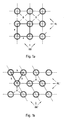
- a register is therefore symmetrical in itself. To describe the structure of a register, so the exact arrangement of the tubes with each other, serves the so-called division.
- a triangular division If the tube rows and the tube layers are not aligned perpendicular to one another, this is called a triangular division.
- the tube centers of three adjacent tubes lie on the corners of a triangle, which may be isosceles but does not have to. If the side lengths of such a triangle are known, then the arrangement of the tubes in the register is also clearly defined, as if the side lengths of a square or rectangular area formed by the tube centers of adjacent tubes are predetermined in the case of square or rectangular divisions. Within a register, the distances concerning the respective division do not change. Registers with a square pitch and a triangular pitch are for better clarity in the Fig. 1a and 1b shown schematically.
- a heat exchanger may have one or more registers.
- the heat exchangers are used for heat exchange between different fluids, which may be liquid or gaseous.
- the fluid flowing through the register is referred to hereinafter as Nutzfluid and the fluid flowing through the tubes of the register referred to as heat transfer fluid.
- the useful fluid of a heat exchanger can be used, if required, as the heat transfer fluid of another heat exchanger.
- the useful fluid is treated after leaving the one heat exchanger and before entering the other heat exchanger as a heat transfer fluid regularly in a further process stage, such as condensation or deposition of interfering components.
- heat exchangers which are operated in the so-called cross-flow.
- the heat exchanger or at least one register is divided into two separate regions, so that flow in the two areas of different Nutzfluide to the tubes of the register.
- the flow direction of the Nutzfluide can be opposite.
- the heat transfer fluid within the tubes of the register in this case transports heat from one area of the register to the other area of the register, so that the one useful fluid gives off heat to the other use fluid.
- the used fluids can be one and the same fluid flow at two different points in time during a process-related process, for example for the treatment, conditioning and / or purification of the fluid flow.
- the heat exchangers or registers are used, for example, to cool or heat up a useful fluid in the form of a flue gas which arises during the combustion of a fuel.
- the heat exchangers For example, integrated into an emission control system.
- a flue gas scrubber in the form of a gas cooler while provided for the heating of flue gases heat exchanger can be followed by a flue gas scrubber to dry the flue gas.
- the temperature of the flue gas is raised to a higher temperature level in order to avoid condensing of individual components in downstream system parts.
- both gas cooler and gas dryer can be provided.
- Interfering components can have a considerable amount of interfering components. These interfering components are predominantly particles, for example in the form of dusts.
- interfering components can also be liquids, such as, for example, condensate or washing liquid entrained at the outlet of an upstream scrubber. The liquid is distributed over a large number of individual droplets.
- the condensate can be an acid or an aqueous acidic solution, in particular in the treatment of flue gases.
- the condensate as other liquids and / or solids can be introduced into the heat exchanger. But the condensate can also be formed only in the heat exchanger or in at least one register of the heat exchanger by a drop in temperature.
- the aggregate state of the interfering component differs from that of the useful fluid.
- the interfering components in a working fluid such as a flue gas, may be homogeneous, such as of the same substance, or heterogeneously composed of different substances.
- the interfering components can get stuck in the heat exchanger, in particular in at least one of the registers of the heat exchanger and accumulate there. Therefore, registers operated with service fluids with a higher concentration of interfering components should be periodically cleaned to avoid clogging of the register between individual tubes. Furthermore, it may also be undesirable if the interfering components are simply discharged with the Nutzfluid.
- flushing medium For cleaning, a larger amount of flushing medium is often supplied to the working fluid prior to entry into the register during operation, which is then entrained by the flow of the Nutzfluids and carried through the register. This usually happens in more or less regular, predetermined time intervals.
- the flushing medium can also be introduced evenly distributed within the tube bundle of the heat exchanger.
- the flushing medium which is usually water, should in any case come into contact with the accumulating in the register interfering components and carry them out together with the flushing medium, in particular in the flow direction of the Nutzfluids from the register.
- the register has the least possible tendency to accumulate interfering components and at the same time be well cleaned
- the register is constructed in such a way that the useful fluid has a high flow velocity between the tube layers which are regularly aligned parallel to the outflow direction of the useful fluid. This is achieved in particular by the fact that the registers of tubes with relative are constructed large diameters, which are arranged at large distances from each other. Ultimately arise between the pipe layers broad flow paths, which oppose the Nutzfluid a low flow resistance and can be flowed through by the Nutzfluid quickly.
- the present invention is therefore the object of a register and a heat exchanger of the type mentioned in such a way and further that when operating with Nutzfluiden with high levels of interfering components such as flue gases, the tendency to fouling and blocking is reduced and thus in a continuous Operation longer service life can be achieved.
- the present invention has recognized that, contrary to the prior teaching regarding the design of heat exchanger registers, the symmetrical arrangement of the tubes in the registers is disadvantageous in terms of undesirable accumulation of interfering components in continuous operation.
- this knowledge is used to move away from a highly symmetrical structure of the register and to create a register which is deliberately constructed asymmetrically to a certain extent.
- This certain asymmetry is created by providing flow lanes with significantly different lane widths in the register.
- a significantly different lane width in this context means that the lane widths differ significantly from one another in such a way that the flow resistance in the flow lanes differ significantly from one another.
- the difference between the widths of the lanes depends on the working fluid and the process conditions and therefore can not be exactly quantified.
- a small lane width is so small that the Nutzfluidströmung is delayed such that there is a significant decrease in entrained by the Nutzfluid Störkomponenten.
- the flow velocity is so high that the delay of the Nutzfluidströmung can be compensated in the areas of narrow lane width.
- This preferably means that at constant pressure loss, the same volume flow of useful fluid flows through the register as in a symmetrical arrangement of the tubes in the register. Depending on the available pressure loss, it does not depend on an exact adherence to said relationship. In addition, it is assumed in this pressure loss consideration of an unpolluted register. Otherwise, in a conventional register due to the higher deposits of interfering components the Nutzfluidströmung be the same pressure loss significantly lower than in the previously described register.
- the large lane width may be more than 1.10, more than 1.25, more than 1.5, more than 2.0, more than 2.5 or more than 3.0 times as wide depending on the application as appropriate the narrow lane width. In principle, therefore, a significant difference between the large and the narrow lane width is preferred. However, it may simultaneously or alternatively be an obstacle to the flow distribution within the register if the differences between the large lane width and the narrow lane width are too clear, so that may form ineffective dead zones in which there is no flow. Too large differences in the lane widths may alternatively or additionally reduce the heat transfer area as the sum of the lateral surfaces of the tubes of the register, which may adversely affect the heat to be transferred per volume of the register. The large lane width should therefore not be more than 5, not more than 4, not more than 3 or not more than 2 times as wide as the narrow lane width, if necessary.
- the interfering components in the calm zones in the register ie in the area of the small widths of the lane, can drop in the direction of gravity, a situation arises Removing the Nutzfluids of interfering components.
- the interference components can thereby sink completely downwards, wherein the sunken interference components are preferably drawn off in some way in order to prevent accumulation.
- a partial flow of the interfering components entering the register will fall in the direction of gravity and be withdrawn at the bottom of the register, while the other part will be discharged from the register with the working fluid in the direction of flow of the useful fluid.
- Corresponding heat exchangers are preferably designed as gas coolers. If the heat exchanger is designed as a gas dryer in which the Nutzfluid is heated, and if the interfering components with the Nutzfluid are registered droplets, which are entrained, for example, from an upstream scrubber or mist eliminator, it is preferred that the spurious components substantially completely down dissipate and withdraw the Nutzfluidstrom after its entry into the register in this way quickly.
- the interfering components can thus optionally have a homogeneous or an inhomogeneous composition, wherein the interfering components also consist of different materials and may, if necessary, have different states of aggregation.
- the heat transfer fluid flowing through the tubes may, if necessary, be a so-called heat transfer medium provided specifically for the transport of heat. In particular, water and oils are considered.
- the heat transfer fluid may also be a process medium, which, like the used fluid, preferably also exists anyway and preferably has to be heated or cooled anyway.
- the heat transfer fluid may for example also be a flue gas.
- Heat transfer fluid and working fluid may optionally be gaseous and / or liquid.
- the Nutzfluid is a flue gas, more preferably, a flue gas to be cooled or aufloomendes.
- the register is used for indirect heat exchange, since the heat transfer fluid and the Nutzfluid not come into direct contact with each other, but the heat is transferred only through the pipe walls.
- the register has a plurality of tube layers and tube rows, wherein the tubes of a row of tubes are part of different tube layers and vice versa.
- the pipe layers extend substantially in the flow direction of the Nutzfluids, while the rows of tubes obliquely, possibly transverse, aligned with the flow direction of the Nutzfluids.
- the tubes of at least one tube layer can in each case be arranged in alignment with one another in the direction of flow of the useful fluid or else offset relative to one another, while the tubes of at least one row of tubes are aligned transversely to the flow direction of the useful fluid one behind the other or else arranged offset to one another.
- the width of a flow alley always determines itself in a row of pipes, by the distance between two adjacent, the flow path limiting tubes.
- the lane width of at least one flow lane of a register from tube row to tube row can vary or even remain constant.
- the narrow and wide sections of row of tubes to row of tubes in the flow direction of the Nutzfluids can be arranged uniformly one behind the other.
- a narrow section follows a further section in the flow direction in the following row of tubes, or that the width of the narrow and wide sections varies in successive rows of tubes as well as in one and the same row of tubes.
- any plurality of rows of pipes, pipe layers and / or flow paths may be meant.
- it may be an overwhelming majority, with a share exceeding 50%.
- all or substantially all rows of tubes, pipe layers and / or flow paths may also be meant.
- a first embodiment of the register can be provided for a simple production and a simple design of the register that at least individual Flow paths of the register in the flow direction of the Nutzfluids successive rows of tubes of the register have a constant lane width.
- the lane width of the same flow path thus does not change during the transition from one row of tubes to the next row of tubes in the flow direction.
- the register thus constructed has flow paths which are formed identically in successive rows of tubes. In this case, these flow paths in the direction of the respective tubes have a constant or even a varying width of the lane.
- at least one flow lane has a constant lane width along all tube rows of the register.
- the corresponding flow lane does not necessarily have to have a constant lane width in the direction of the tubes, but may possibly have both narrow and wide sections with correspondingly small and large lane widths alternately.
- each tube in at least one row of tubes each tube is fixed to a holding element which is rod-shaped and extends substantially along the tube layers.
- the influence of the flow can be minimized.
- the rod-shaped holding elements of a row of tubes disturb the sinking of the interference components only minimally.
- the at least one retaining element can also be curved in the shape of a lattice or, in particular, around tubes adjacent to the retaining element.
- the holding elements interfere with this Lowering of interference components as little as possible and allow, if necessary, in addition a certain mobility of the tubes, especially if they are arranged flexibly.
- materials for the production of the holding element are quite generally metals, ceramics or plastics in question, wherein the metals may have a corrosion protection, which is formed, if necessary, by a plastic sheath.
- Fluoroplastics are particularly suitable as plastic for the retaining element or the jacket.
- exactly one pipe layer is fixed to at least one retaining element of the register, while exactly two adjacent pipe layers are fixed to at least one other retaining element. This is particularly useful when using pipes with different diameters in at least one row of pipes. Then, for example, a pipe layer with pipes of a large diameter can alternately be fastened to a separate retaining element, while adjacent thereto two pipe layers with pipes of smaller diameter are fixed to a common retaining element arranged between the pipe layers.
- the holding elements can also serve to position the tubes of at least one row of tubes or of the entire register.
- the holding elements have spacers for spacing the tubes fixed to the holding elements between the tubes fixed to the holding elements at least one row of tubes.
- the holding elements are formed directly as spacers. They then have between the respective pipes to be spaced to a width corresponding to the desired distance of the tubes, without the need for another component.
- the holding elements do not interfere too much with the flow of the useful fluid through the register, it is advantageous if the holding elements are arranged either in flow lanes with a small lane width and / or in narrow sections of the respective flow lane of at least one row of tubes.
- the tubes in these flow paths and / or sections in any case a small distance from the adjacent tubes, so that a material-saving fixation of the tubes can be achieved.
- the retaining elements disturb the sinking of interfering components in calmed zones only slightly, since the holding elements are arranged laterally on the tubes.
- the retaining element can also be arranged in the flow paths with a large lane width and / or in wide sections. Then, on a holding element settling interfering components are easily removed and do not accumulate so much during operation.
- the holding element is then preferably aligned along a flow lane with a wide lane width and extends in this flow lane along a pipe layer delimiting the flow lane. In this case, holding sections of the holding element can then be provided which connect the tubes of this tube layer to the holding element.
- the tubes of the register can in at least one row of tubes in at least one flow alley with a narrow lane width or in a narrow Section may be provided a purge line for supplying flushing medium.
- the flushing line extends substantially in the direction of the pipe layers and / or in the direction the flow paths, which preferably corresponds to the same direction.
- a purge line is provided.
- a flushing line may be provided in the narrow sections of the flow lanes in flow lanes with a varying lane width on a common plane. Wide sections of flow passages of the register can, if necessary, manage without flushing line.
- the rinse lines can be designed as spacers for spacing the rinse line of adjacent tubes of the at least one row of tubes. This is achieved structurally simply in that the flushing lines have a diameter which corresponds to the preferred distance of the adjacent tubes in the region of the respective flushing line.
- the flushing lines can also each in the flow alley with the small lane width and / or the narrow section the flow alley be arranged because the flushing liquid can be selectively supplied to the calmed zones, the flow is not affected in the flow lanes with large lanes widths and the pipes are already close to each other in said flow paths and / or said sections.
- At least one holding element may be formed simultaneously as flushing line or vice versa.
- the at least one retaining element has a substantially closed profile, which can be flowed through by the flushing medium, wherein the flushing medium can escape through a series of openings from the corresponding profile.
- At least one pipe layer is aligned at least in sections obliquely and / or curved with respect to the direction of flow of the. Register by the Nutzfluid. This has the consequence that the free flow path for the Nutzfluid opposite the direction of flow of the register is inclined.
- the Nutzfluid as such is preferably deflected, in the direction of the free flow lane.
- the spurious components which preferably have a higher density, are exposed to a higher inertia influence and are less strongly or hardly deflected.
- the tubes of a tube layer are preferably arranged offset from each other, so that the interference components as needed in the further flow against a tube further downstream in the direction of flow bounce tube row or preferably against a further downstream in the direction of flow pipe of a flow path defining pipe layer.
- the flow rate of the Nutzfluids is reduced, so that the bouncing against a pipe noise components can easily get down in the direction of gravity.
- the tubes arranged one behind the other in the flow direction are each offset only by a part of the width of the lane.
- the tubes are then not set to gap with each other, which is unfavorable in terms of flow, but are always in the defined by the front row of tubes flow in it. It can then expand on the other side of the flow alley in the same or similar extent, so that the flow path has a total along at least one pipe layer substantially a constant width of the lane.
- the flow path is slightly inclined to the flow direction of the register. This arrangement has the effect that jamming components entrained by the working fluid, in particular in the form of droplets, do not readily flow through the register, but with a higher probability strike against one of the tubes of the register projecting in the direction of flow into the flow lane.
- At least two pipe layers define a flow path with an inlet-side opening and an outlet-side opening for the useful fluid between them such that the inlet-side opening in the direction of flow of the user fluid with respect to the register does not overlap with the exit opening.
- An interfering component such as in the form of a droplet, can then not, or at least hardly, be carried straight through in the direction of flow of the register through this. Rather, there is a very high probability that the droplets will hit pipes of one of the pipe layers and be deposited accordingly. Thus, a Entfrachtung the Nutzfluids about entrained liquid is easily possible.
- the inlet-side opening is the lane width of the flow lane formed in the direction of flow of the useful fluid in the foremost row of tubes, while the outlet-side opening is analogous to the lane width of the flow lane of the rearmost row of tubes.
- the register instead of the register as such, reference may also be made to a partial region of the register, so that further tubes or rows of tubes may be provided on the inlet side and / or outlet side.
- flow paths are arranged with constant lane widths. This is easy and inexpensive to realize, especially with straight pipes. Nevertheless, an asymmetry can, if necessary, be created in a row of pipes by providing flow paths there which have widths of the lane varying along the longitudinal extension of the pipes, that is to say preferably wide sections and narrow sections.
- the register becomes even simpler and less expensive if at least the flow paths located in a row of pipes each have a constant width of the lane.
- the lane width is constant in the direction of the longitudinal extent of the tubes.
- Preferably the lane widths in all pipe rows of the register are constant. This allows a very simple and therefore cost-effective design of the register, wherein the tubes are formed in particular straight.
- At least one flow channel is arranged with alternating narrow sections and wide sections. This makes it possible, for example, to build a register with the desired asymmetry by a combination of flow lanes with a constant lane width and flow lanes with a varying lane width in a row of tubes or in different rows of tubes.
- the flow paths are understandably provided in the longitudinal extension of the tubes with a constant or varying width of the lane.
- all flow paths are each equipped with varying lane widths in at least one row of tubes, alternating in each individual flow lane of the row of tubes narrow sections and wide sections.
- Another, possibly additional way to provide an imbalance in the register, without the register is random and thus complicated to build and interpret, could consist in at least one row of tubes in a direction perpendicular to the tubes of the row of tubes narrow sections and wide sections adjacent Flow lanes next to each other to arrange alternately to each other.
- the register thus constructed has flow paths which, in successive rows of tubes, have a shape which varies in the direction of flow of the useful fluid and preferably alternates.
- the shape of the flow paths thus varies and allows a non-symmetrical structure of the register, which follows at the same time clear rules and thus can be easily manufactured and calculated for the purpose of interpretation.
- One way to summarize areas with a large lane width and a small lane width in a register is that at least individual tubes at least one row of tubes are partially part of a first layer of pipe and partially part of a second layer of pipe.
- the corresponding tubes thus extend in sections in the one tube layer and in sections in at least one other tube layer. This arises, for example, when adjacent tubes of a row of tubes crossed with each other be, with a pipe from one pipe layer of the tube row to the other adjacent tube layer of the tube row is performed, while the adjacent tube is guided from the adjacent other tube layer to a tube layer.
- a corresponding crossing of the tubes can be provided in a series of tubes in a flow alley simple or repetitive multiply.
- tubes of any pipe layers in a row of pipes can be crossed with each other or any pipes of a pipe layer can be crossed with each other. It is also possible to intersect pipes that belong on the one hand to different rows of pipes and on the other hand to different pipe layers. For the sake of simplicity, however, it is provided that adjacent tubes of a row of tubes extend in sections in immediately adjacent tube layers of the tube row.
- a simple, regular but not symmetrical construction of the register can be achieved if a flow path defined by a first pipe layer and a second pipe layer has a plurality of narrow sections and / or wide sections in at least one row of pipes.
- a flow path defined by a first pipe layer and a second pipe layer has a plurality of narrow sections and / or wide sections in at least one row of pipes.
- exclusively wide sections exclusively narrow sections or wide and narrow sections alternately, and preferably alternately provided. Only narrow portions occur when the tubes of the two flow path defining tube layers of a row of tubes along the longitudinal direction of the tubes always alternately with each other are crossed and between the crossing points only narrow flow cross sections remain free.
- the wide sections are then preferably provided in adjacent flow paths of the same row of tubes. For this purpose, it is then sufficient if necessary, if the adjacent tubes of the row of tubes are rectilinear, because the crossed tubes ensure that the forming lane width of the adjacent flow lane varies.
- an asymmetry of the register can be provided in a simple manner by at least individual tubes of at least one row of tubes, preferably several times, being crossed with one another along the longitudinal extent of the tubes.
- a relatively regular structure of the register with a large number of wide sections and narrow sections results when substantially all tubes of at least one row of tubes, preferably several times, are crossed along the longitudinal extent of the respective tubes with adjacent tubes.
- the crossing points of crossed tubes can lie on the same planes perpendicular to the longitudinal extent of the tubes, as the crossing points of the adjacent crossed tubes.
- the crossing points of crossed tubes can lie on a first row of planes, while the points of intersection of the adjacent tubes of the tube row lie on a second row of planes, which are also aligned perpendicular to the longitudinal extent of the tubes.
- each two crossed tubes always lie alternately on the first row of planes and the second row of planes. Adjacent crossed tubes are thus always arranged alternately offset in the longitudinal direction of the tubes by the distance of the planes of different rows against each other.
- Varying widths and thus a targeted asymmetry of the register can be structurally particularly simple achieve that are provided in at least one row of tubes and / or in at least one tube layer tubes with significantly different tube diameter.
- pipes with different diameters can be arranged alternately and in relation to one another in the at least one row of pipes or pipe layers so that the flow paths with different widths of the lanes result therefrom.
- each tube adjacent at least one row of tubes with a larger diameter each two tubes of at least one row of tubes is arranged with a small diameter.
- two thin tubes follows a thick tube, which then again follow two thin tubes, etc.
- the tubes are made of a plastic, preferably of a fluorine plastic, in particular of perfluoroalkoxy (PFA). This achieves high resistance to corrosive media.
- the tubes can be made of metal, preferably made of a correspondingly resistant, in particular made of a corrosion-resistant metal.
- the tubes may be flexible in order to be able to easily arrange the tubes in the desired alignment with one another. This is especially the case when individual tubes should be crossed with each other. The necessary flexibility can be ensured by the said plastic material of the tubes readily.
- the register may also have both flexible and rigid tubes. This is useful, for example, if the rigid tubes are to contribute to the stability of the register.
- the tubes with a larger diameter are rigid and the tubes with a smaller diameter are flexible.
- rectilinear tubes of a register are rigid and the bent tubes of the same register are flexible.
- the flexible tubes are made of a plastic and the rigid tubes are made of metal.
- the tubes of at least two adjacent tube layers with staggered tubes can be brought very close to each other, if necessary even overlapping. Then remain between the corresponding tubes, if at all, only very narrow gaps transverse to the flow direction of the Nutzfluids.
- the tubes ultimately together form a so-called tube disc, which reflects the sound waves to a high degree.
- at least one corresponding pipe disk can be provided in that the pipes of at least one pipe layer are brought so close together that no or only very small spaces remain between the pipes of this pipe layer. In order to achieve this, either in the at least one pipe layer, the number of pipes is significantly increased compared to other pipe layers or their diameter significantly increased compared to other tubes of the register.
- the tubes of the at least one tube layer for the reflection of the sound can be rigid, for example made of metal.
- a heat exchanger with at least one register according to claim 13, characterized in that the at least one register is a register according to one of claims 1 to 12.
- a transversely oriented to the flow direction barrier to protect the pipes from abrasion is provided by entrained by the Nutzfluid Störkomponenten.
- the interfering components are in particular particles, such as dusts or the like.
- the barrier is preferably applied where local peaks of the concentration of interfering components occur. This is due to the influence of gravity on the spurious components regularly at the bottom of the heat exchanger of the case.
- the barrier is therefore preferably provided in the direction of gravity lower end of the register.
- the barrier forms a gap with the bottom of the heat exchanger.
- the Nutzfluid flows at an increased speed and can thus entrain on the bottom of the heat exchanger accumulating and / or preferably sunk in the calm zones down towards the ground Stör components and carry out in this way from the heat exchanger.-This ultimately leads to a Entfrachtung with the Nutzfluid.
- the height of the free gap corresponds at most approximately to the minimum distance between the lower end of the register and the bottom of the heat exchanger, so that the lower end of the register is not exposed to increased abrasion by the interfering components.
- the register is preferably as a hung U-tube heat exchanger coil with pipe bends on formed in the direction of gravity lower end of the register.
- the lane width is maximum.
- this at least one flow path widens downward to improve the removal of jamming components from the register, even if this results in the lane width of adjacent flow lanes being correspondingly lower, so that the width of the register can remain constant overall.
- the lane width is substantially zero in at least one row of pipes at least in a flow lane with a small lane width.
- the corresponding adjacent tubes of at least one row of tubes can thereby, preferably almost, abut each other.
- the above-described structural features of the register of the heat exchanger can in principle be combined with one another in any desired manner. This is especially true in the various ways described, deviating from a symmetrical structure of a register of a heat exchanger. It can therefore be made, for example, in different rows of tubes and / or pipe layers of different types of asymmetrical design and / or different dimensions of a particular unbalanced design use. It could also be in one and the same Tube row and / or pipe layer of different such configurations use made. In order to keep the complexity with regard to the manufacture and the design of the register low, it is nevertheless appropriate if in each case one row of tubes and / or one tube layer use is made of only one embodiment, which leads to an overall asymmetrical structure of the register. In other words, then different pipe layers and / or rows of pipes structurally different from each other.
- the register described above is particularly well suited due to its design for heating and / or cooling gas containing interfering components, in particular flue gas.
- the interfering components may be particles, condensate and / or entrained liquid. Therefore, the effects of the register come into play especially when it is before and / or downstream of a flue gas scrubber (claim 17). Then the flue gas is heated and / or cooled.
- a detail of a heat exchanger 1 is shown, which has a register 2 with parallel aligned pipes 3.
- the register 2 perpendicular to the flow direction S of the Nutzfluids a series of successively arranged rows of tubes 4, which form mutually parallel pipe layers 5 in the flow direction S of the Nutzfluids.
- the individual tubes 3 of each tube layer 5 are arranged in alignment in the flow direction S of the Nutzfluids one behind the other.
- each flow lane 6,6 'in each row of tubes 4 a lane width 7,7', which is determined by the distance between adjacent tubes 3.
- the lane width 7,7 'of each flow path 6,6' in the flow direction S of the Nutzfluids constant.
- the lane width 7,7 'of the flow paths 6,6' therefore does not change from tube row 4 to tube row 4 of the register 2.
- the lane width is 7,7 'aligned in the illustrated embodiment, each perpendicular to the flow direction S of the Nutzfluids.
- flow paths 6,6 ' alternate with a large lane width 7' and a small lane width 7. Due to the larger lane width 7 'is in the corresponding flow paths 6', a higher flow rate of the Nutzfluids, while due to the lower Gassenbreite 7 sets a lower flow velocity of the Nutzfluids in the remaining flow paths 6.
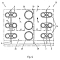
- the in the FIGS. 2 and 3 3 shown tubes are each paired in pairs and fixed to a common support member 8, which is rod-shaped and extends parallel to the adjacent pipe layers 5, ie along the flow path 6, with small lane width 7.
- the holding elements 8 are held in the illustrated plane of the register 2 on a transversely extending to the register 9 suspension.
- the holding elements 8 have spacers 10, on each of which two adjacent sides of two pipes 3 different pipe layers 5 are in abutment.
- For fixing each two adjacent tubes 3 different pipe layers 5 on the support member 8 is a tube 3 encompassing ring element 11.
- Fig. 4 is another detail of the register 2 according to FIGS. 2 and 3 shown, in Fig. 4 a view corresponding to the Fig. 2 is shown, however, which shows a section in a region in which flushing lines 12 are provided for flushing and thus for removing interference components from the register 2.
- the purge lines 12 may be arranged differently high in the register. In any case, at least some of the purge lines 12 are arranged relatively high in the register 2. Furthermore, the purge lines 12 are provided only in each second flow path 6. In this case, the purge lines 12 extend in It is also possible, although not shown in detail, that the flushing lines 12 are fastened to holding elements 8 substantially along the entire flow paths 6 through the register 2.
- the purge lines 12 are provided in the narrower flow paths 6 and also have an outer diameter which coincides with the smaller lane width 7 of these flow paths 6 substantially.
- the flushing lines 12 have openings over their length, not shown, from which a flushing medium, such as water, specifically exit can.
- a flushing medium such as water
- the lane width 7,7 'of the respective flow path 6,6' does not vary over the height of the illustrated register 2, but remains constant. This is achieved in particular by the fact that the tubes 3 run parallel to one another.
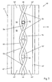
- Fig. 5 is a register 2 'shown schematically in a section perpendicular to the longitudinal extent of the tubes 3.
- the pipe layers 5 ' are not parallel, but obliquely aligned to the inflow direction AS of the Nutzfuids with respect to the register 2'.
- This is going through a small offset of the rows of tubes 4 'following each other in the direction of flow AS is achieved by a large part of the lane width of the flow lane 6 ", thus forming flow lanes 6" where the inlet-side openings 14 of the flow lanes 6 "do not for the useful fluid overlap more with the outlet-side openings 15 of the flow paths 6 ".
- register 22 of a heat exchanger 21 differs from that in the Fig. 2 to 3 Register 2 shown by the fact that pipes are installed 3,23 different diameters.
- 5.25 exclusively tubes 3.23 are provided with identical diameter in each pipe layer.
- the pipe layers 5,25 are also so assembled to the register 22 that follow two pipe layers 5 with pipes 3 small diameter always a pipe layer 25 of a large diameter and this always two pipe layers 5 with pipes 3 small diameter.
- the two adjacent pipe layers 5 with pipes 3 of smaller diameter are held by a common holding element 8 which extends along the flow path 6 formed by these two pipe layers 5 and is also formed rod-shaped.
- each tube layer 25 with tubes 23 of a large diameter is held by a separate holding element 28, which is arranged laterally to the tube layer 25. Therefore, this holding element 28 also comes without separate spacers.
- the two adjacent pipe layers 5 with tubes 3 of a smaller diameter are in the illustrated embodiment, as already to the Fig. 2 to 4 described constructed. The same applies in principle for the arrangement of the purge line in the flow paths 6 with a small lane width 7, so the flow paths 6 between the pipe layers 5 with tubes 3 of a small diameter. That in the Fig. 6 shown register 22 has exclusively rectilinear tubes 3.23. It could also be used in any case partly curved pipes to build the register.
- register 42 of a heat exchanger 41 is similar to that in the Fig. 2 shown register 2, only the foremost row of tubes 44 shown, since the other rows of tubes 44 are arranged in alignment with the front row of tubes 44.
- the peculiarity of in the Fig. 7 represented register 42 in comparison to the register 2 according to the Fig. 2 to 4 is that the tubes 43 are alternately part of a first pipe layer 45 and a second pipe layer 45 'of the common pipe row 44.
- the tubes 43 cross each other in the transition from the first tube layer 45 to the second tube layer 45 'and vice versa.
- a flow lane 46 with narrow sections 54 ie smaller lane widths 47, is formed.
- Some of the narrow portions 54 have one Spacer 50 or a purge line 52 on.
- the purge line 52 has the same outer diameter as the spacer 50, so that the purge line 52 holds the two pairs crossed tubes 43 at the same time to each other at the desired distance.
- the illustrated crossed tubes 43 are rigid, so that between two points of intersection 53 of the tubes 43 not in any case a means must be provided, which contributes to the spacing of the tubes 43.
- a means which contributes to the spacing of the tubes 43.
- Such means would preferably be provided between each two adjacent crossing points of a flow, so that the tubes permanently occupy the desired position.
- the flow lanes 46 'adjacent to the two crossed tubes 43 have varying lane widths 47'.
- the flow paths 46 ' are at the level of the intersection points 53 widest and mid-height between the intersection points 53 narrowest.
- the flow channels 46 'adjoining the crossed tubes 43 which are delimited by the adjacent rectilinear tubes 43' of the tube row 44, again alternately have narrow sections 54 'and further sections 55 over their height.
- register 42,62 alternate pairs crossed tubes 43,63,63 'and rectilinear tubes 43', 63 "in a row of tubes 44,64 from each other.
- register 82 has only pairs crossed tubes 83.
- the points of intersection 93 of the pairs of crossed tubes 83 in any case of one row of tubes 84 lie in common planes 96 parallel to the flow direction.
- the paired crossed tubes 83 each define a flow path 86 'therebetween having only narrow portions 94' with smaller lane widths 87 ", which need not be identical to the narrow portions 94 'of the respective adjacent flow lanes 86.
- the points of intersection of adjacent tubes could also lie on different planes.
- the points of intersection of two tubes crossed with one another in the longitudinal extent of the tubes and / or the register lie substantially, in particular centrally, between the points of intersection of the adjacent crossed tubes, in particular on both sides of the tube row.
- the crossing points of these adjacent to both sides of the row of tubes, each pairwise crossed tubes are then preferably on common levels, especially with the crossing points of the next but one another in pairs crossed tubes of at least one row of tubes.
- a corresponding arrangement has the consequence that the flow path between each two pairs crossed pipes over the flow path height has a relatively uniform lane width. According to a corresponding embodiment, the corresponding flow path would assume a substantially serpentine shape.
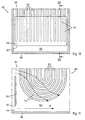
- the bottom portion of a heat exchanger 101 is shown with U-shaped tubes 103.
- the U-shaped tubes 103 of the register 102 are suspended in the heat exchanger 101 in the direction of gravity, so that the tube curves 117 of the U-shaped tubes 103 point in the direction of the bottom 118 of the heat exchanger 101.
- Between the curved tubes 103 and the bottom 118 of the heat exchanger 101 remains a gap 119 through which the working fluid can flow.
- a barrier 120 which is shown in the form of a plate and extends in a plane perpendicular to the flow direction S of the useful fluid in the illustrated embodiment.
- the barrier 120 is arranged such that between the bottom 118 of the heat exchanger 101 and the lower edge 121 of the barrier 120, a gap 119 is formed, through which the useful fluid flows at an increased speed and in the bottom area separated entrainment components, such as particles entrains, without This can lead to an increased abrasion at the register 102 in the region of the pipe bends 117.
- This increased flow rate of the Nutzfluids in the gap 122 below the pipe bends 117 is schematically in the sectional view of Fig. 11 shown.
- the stagnation of the Nutzfluids in the flow direction S in front of the barrier 120 also results in increased flow velocities in the overflow of the barrier 120 through the Nutzfluid, which thus flows at an increased flow rate through the region of the tube curvatures 117 and there interference components, from the top of the flow of Nutzfluids have sunk, removed.
- the flow lanes can be widened with large lane widths in the region of the lower end of the register where the pipe bends are located, whereby the flow lanes are narrowed locally with small lane widths. This can have a positive effect on the removal of the interfering components from the register.
Landscapes
- Engineering & Computer Science (AREA)
- Mechanical Engineering (AREA)
- General Engineering & Computer Science (AREA)
- Physics & Mathematics (AREA)
- Thermal Sciences (AREA)
- Chemical & Material Sciences (AREA)
- Combustion & Propulsion (AREA)
- Heat-Exchange Devices With Radiators And Conduit Assemblies (AREA)
Priority Applications (1)
| Application Number | Priority Date | Filing Date | Title |
|---|---|---|---|
| PL10724862T PL2452147T3 (pl) | 2009-07-06 | 2010-06-17 | Pęczek rur do pośredniej wymiany ciepła |
Applications Claiming Priority (2)
| Application Number | Priority Date | Filing Date | Title |
|---|---|---|---|
| DE102009031969A DE102009031969A1 (de) | 2009-07-06 | 2009-07-06 | Rohrregister für den indirekten Wärmeaustausch |
| PCT/EP2010/058564 WO2011003717A2 (de) | 2009-07-06 | 2010-06-17 | Rohrregister für den indirekten wärmeaustausch |
Publications (2)
| Publication Number | Publication Date |
|---|---|
| EP2452147A2 EP2452147A2 (de) | 2012-05-16 |
| EP2452147B1 true EP2452147B1 (de) | 2013-10-16 |
Family
ID=43307727
Family Applications (1)
| Application Number | Title | Priority Date | Filing Date |
|---|---|---|---|
| EP10724862.7A Active EP2452147B1 (de) | 2009-07-06 | 2010-06-17 | Rohrregister für den indirekten wärmeaustausch |
Country Status (8)
| Country | Link |
|---|---|
| US (1) | US10048012B2 (ar) |
| EP (1) | EP2452147B1 (ar) |
| KR (1) | KR101243355B1 (ar) |
| CN (1) | CN101943540B (ar) |
| CA (1) | CA2780585C (ar) |
| DE (1) | DE102009031969A1 (ar) |
| PL (1) | PL2452147T3 (ar) |
| WO (1) | WO2011003717A2 (ar) |
Families Citing this family (5)
| Publication number | Priority date | Publication date | Assignee | Title |
|---|---|---|---|---|
| US10302369B1 (en) * | 2013-02-25 | 2019-05-28 | U.S. Department Of Energy | Non-vaned swirl core configurations |
| CN105043128A (zh) * | 2015-06-11 | 2015-11-11 | 成都佳美嘉科技有限公司 | 冷却喷淋塔 |
| EP3115734A1 (en) * | 2015-07-06 | 2017-01-11 | Casale SA | Shell-and-tube equipment with antivibration baffles and related assembling method |
| KR101887743B1 (ko) * | 2016-04-22 | 2018-08-10 | 현대자동차주식회사 | 차량의 배기 시스템 및 그 제어방법 |
| GB2575674B8 (en) | 2018-07-19 | 2021-08-18 | Perkins Engines Co Ltd | Exhaust mixer, emissions cleaning module and method of manufacture |
Family Cites Families (35)
| Publication number | Priority date | Publication date | Assignee | Title |
|---|---|---|---|---|
| US2621903A (en) * | 1949-07-02 | 1952-12-16 | Irving H Cohler | Heat exchange tubing |
| GB813152A (en) * | 1956-04-09 | 1959-05-13 | Konink Machinenfabriek Gebr St | Improvements in and relating to heat exchangers |
| US3415316A (en) * | 1967-04-11 | 1968-12-10 | Olin Mathieson | Modular units and use thereof in heat exchangers |
| GB1244611A (en) * | 1967-12-01 | 1971-09-02 | Atomic Power Constr Ltd | Improvements in or relating to heat exchangers |
| AT313934B (de) * | 1971-08-03 | 1974-03-11 | Waagner Biro Ag | Wärmetauscher und Verfahren zu seiner Herstellung |
| JPS5949495A (ja) | 1982-09-13 | 1984-03-22 | Babcock Hitachi Kk | 熱交換装置 |
| JPH0710967B2 (ja) * | 1985-02-04 | 1995-02-08 | 日立化成工業株式会社 | 印刷配線板基板用接着剤 |
| US4827953A (en) * | 1987-03-18 | 1989-05-09 | Electric Power Research Institute, Inc. | Flexible lance for steam generator secondary side sludge removable |
| US4753197A (en) * | 1987-12-10 | 1988-06-28 | The Babcock & Wilcox Company | Tube support |
| US5092280A (en) * | 1988-04-19 | 1992-03-03 | Westinghouse Electric Corp. | Pressure pulse cleaning apparatus |
| DE3841180C1 (en) * | 1988-12-07 | 1990-04-12 | Komotzki, Michael, 5840 Schwerte, De | Heat exchanger |
| CN2108888U (zh) * | 1991-12-10 | 1992-07-01 | 四平市冷却器总厂 | 流体通道横截面积不等的板式换热器 |
| JPH07208889A (ja) * | 1994-01-13 | 1995-08-11 | Mitsubishi Heavy Ind Ltd | プレートフィンアンドチューブ型熱交換器 |
| DE4430338C1 (de) * | 1994-08-26 | 1995-05-04 | Gea Luftkuehler Happel Gmbh | Vorrichtung zur Reinigung von Wärmeaustauschern |
| US5791404A (en) * | 1996-08-02 | 1998-08-11 | Mcdermott Technology, Inc. | Flooding reduction on a tubular heat exchanger |
| DE19647189C1 (de) * | 1996-11-15 | 1998-08-13 | Gea Waerme Und Umwelttechnik G | Wärmetauscher |
| KR19980086240A (ko) * | 1997-05-31 | 1998-12-05 | 윤종용 | 공기조화기용 열교환기 |
| JP3982650B2 (ja) | 1997-12-29 | 2007-09-26 | 臼井国際産業株式会社 | 多管式egrガス冷却装置 |
| CN2330958Y (zh) * | 1998-04-01 | 1999-07-28 | 中国石化茂名石油化工公司 | 双侧相变冷凝器 |
| US6244330B1 (en) * | 1998-11-16 | 2001-06-12 | Foster Wheeler Corporation | Anti-vibration ties for tube bundles and related method |
| FR2793009B1 (fr) * | 1999-04-29 | 2001-07-27 | Valeo Thermique Moteur Sa | Echangeur de chaleur a tubes souples, notamment pour vehicule automobile |
| CN2384188Y (zh) * | 1999-08-12 | 2000-06-21 | 江苏双良锅炉有限公司 | 渐缩流通面积换热器 |
| JP2001116481A (ja) | 1999-10-15 | 2001-04-27 | Calsonic Kansei Corp | 多管式熱交換器 |
| JP2001304605A (ja) * | 2000-04-21 | 2001-10-31 | Hitachi Ltd | 空気調和機 |
| JP3576486B2 (ja) * | 2000-04-26 | 2004-10-13 | 三菱重工業株式会社 | 蒸発器および冷凍機 |
| JP3572250B2 (ja) * | 2000-10-24 | 2004-09-29 | 三菱重工業株式会社 | 冷凍機用凝縮器 |
| JP3961254B2 (ja) * | 2001-09-28 | 2007-08-22 | 株式会社日本触媒 | 多管式熱交換器および該熱交換器を用いる(メタ)アクリル酸の製造方法 |
| CN2667333Y (zh) * | 2003-12-31 | 2004-12-29 | 郑州锅炉有限责任公司 | 凝渣管束 |
| FR2865028B1 (fr) * | 2004-01-12 | 2006-12-29 | Ziepack | Echangeur thermique et module d'echange s'y rapportant |
| JP2005326034A (ja) | 2004-05-12 | 2005-11-24 | T Rad Co Ltd | 高温ガス用チューブ式熱交換器 |
| US20060175048A1 (en) * | 2005-02-10 | 2006-08-10 | Kwangtaek Hong | De-superheated combined cooler/condenser |
| DE102006053812B4 (de) | 2006-11-15 | 2008-08-14 | Flucorrex Ag, Flawil | Rohrabstützung mit integrierter Reinigungseinrichtung |
| FI119897B (fi) | 2007-03-07 | 2009-04-30 | Abb Oy | Järjestely lämmönsiirtimessä |
| US8695688B2 (en) * | 2007-07-18 | 2014-04-15 | Babcock & Wilcox Canada Ltd. | Nubbed U-bend tube support |
| JP5949495B2 (ja) | 2012-11-27 | 2016-07-06 | 富士ゼロックス株式会社 | 印刷システム及びプログラム |
-
2009
- 2009-07-06 DE DE102009031969A patent/DE102009031969A1/de not_active Ceased
-
2010
- 2010-04-26 CN CN201010167743XA patent/CN101943540B/zh not_active Expired - Fee Related
- 2010-06-04 KR KR1020100053039A patent/KR101243355B1/ko active IP Right Grant
- 2010-06-17 US US13/382,431 patent/US10048012B2/en not_active Expired - Fee Related
- 2010-06-17 WO PCT/EP2010/058564 patent/WO2011003717A2/de active Application Filing
- 2010-06-17 PL PL10724862T patent/PL2452147T3/pl unknown
- 2010-06-17 EP EP10724862.7A patent/EP2452147B1/de active Active
- 2010-06-17 CA CA2780585A patent/CA2780585C/en not_active Expired - Fee Related
Also Published As
| Publication number | Publication date |
|---|---|
| CN101943540B (zh) | 2013-07-10 |
| DE102009031969A1 (de) | 2011-01-13 |
| WO2011003717A3 (de) | 2011-07-07 |
| US20120193074A1 (en) | 2012-08-02 |
| CA2780585C (en) | 2014-10-28 |
| KR20110004269A (ko) | 2011-01-13 |
| CN101943540A (zh) | 2011-01-12 |
| CA2780585A1 (en) | 2011-01-13 |
| EP2452147A2 (de) | 2012-05-16 |
| KR101243355B1 (ko) | 2013-03-13 |
| PL2452147T3 (pl) | 2014-07-31 |
| US10048012B2 (en) | 2018-08-14 |
| WO2011003717A2 (de) | 2011-01-13 |
Similar Documents
| Publication | Publication Date | Title |
|---|---|---|
| EP2452147B1 (de) | Rohrregister für den indirekten wärmeaustausch | |
| DE19622424C2 (de) | Rostelement und Rost mit Flüssigkeitskühlung | |
| DE10326381B4 (de) | Turbulenzerzeuger | |
| DE3305471A1 (de) | In einem fliessbett installierter waermetauscher | |
| DE2442420A1 (de) | Desublimator fuer die gewinnung von sublimationsprodukten, insbesondere von phthalsaeureanhydrid, aus reaktionsgasen | |
| EP2547977A2 (de) | Halteelement und spacerebene eines rohrbündels | |
| WO2015188812A1 (de) | Wärmetauscher | |
| DE10013608C2 (de) | Wärmetauscher für ein Gasbrennwertgerät | |
| EP0103202B1 (de) | Roststab für Rostbeläge, insbesondere von Feuerungen | |
| DE102012216146A1 (de) | Wärmeübertragungseinrichtung, Wärmeübertrager sowie Verfahren zur Übertragung von Wärme von einem ersten Fluid auf ein zweites Fluid | |
| DE102006053812B4 (de) | Rohrabstützung mit integrierter Reinigungseinrichtung | |
| DE3725797C1 (ar) | ||
| DE2345175A1 (de) | Kuehlsystem | |
| DE102012007063B4 (de) | Lamellen-Rohr-Wärmetauscher mit verbesserter Wärmeübertragung | |
| DE102016113137A1 (de) | Gas-Fluid-Gegenstromwärmetauscher | |
| DE838647C (de) | Heizkoerper | |
| EP0571656B1 (de) | Wärmetauscher mit zwangsgeführter Strömung | |
| EP3158277B1 (de) | Kühlaggregat | |
| DE3518744C1 (de) | Wärmetauscher mit Reinigungsvorrichtung | |
| DE102012007570B4 (de) | Lamellen-Rohr-Wärmetauscher mit verbesserter Wärmeübertragung | |
| EP0349765B1 (de) | Wirbelschichtfeuerung | |
| DE4244301C2 (de) | Vorrichtung zur Prallkühlung | |
| DE19718064A1 (de) | Turbulenzeinlage | |
| EP2881170B1 (de) | Einbauelement für eine Vorrichtung zur Behandlung eines Fluids | |
| DE102010006371A1 (de) | Wärmetauscher |
Legal Events
| Date | Code | Title | Description |
|---|---|---|---|
| PUAI | Public reference made under article 153(3) epc to a published international application that has entered the european phase |
Free format text: ORIGINAL CODE: 0009012 |
|
| 17P | Request for examination filed |
Effective date: 20120106 |
|
| AK | Designated contracting states |
Kind code of ref document: A2 Designated state(s): AL AT BE BG CH CY CZ DE DK EE ES FI FR GB GR HR HU IE IS IT LI LT LU LV MC MK MT NL NO PL PT RO SE SI SK SM TR |
|
| DAX | Request for extension of the european patent (deleted) | ||
| GRAP | Despatch of communication of intention to grant a patent |
Free format text: ORIGINAL CODE: EPIDOSNIGR1 |
|
| INTG | Intention to grant announced |
Effective date: 20130425 |
|
| GRAS | Grant fee paid |
Free format text: ORIGINAL CODE: EPIDOSNIGR3 |
|
| GRAA | (expected) grant |
Free format text: ORIGINAL CODE: 0009210 |
|
| AK | Designated contracting states |
Kind code of ref document: B1 Designated state(s): AL AT BE BG CH CY CZ DE DK EE ES FI FR GB GR HR HU IE IS IT LI LT LU LV MC MK MT NL NO PL PT RO SE SI SK SM TR |
|
| REG | Reference to a national code |
Ref country code: GB Ref legal event code: FG4D Free format text: NOT ENGLISH |
|
| REG | Reference to a national code |
Ref country code: CH Ref legal event code: EP |
|
| REG | Reference to a national code |
Ref country code: IE Ref legal event code: FG4D Free format text: LANGUAGE OF EP DOCUMENT: GERMAN |
|
| REG | Reference to a national code |
Ref country code: AT Ref legal event code: REF Ref document number: 636701 Country of ref document: AT Kind code of ref document: T Effective date: 20131115 |
|
| REG | Reference to a national code |
Ref country code: DE Ref legal event code: R096 Ref document number: 502010005079 Country of ref document: DE Effective date: 20131212 |
|
| REG | Reference to a national code |
Ref country code: NL Ref legal event code: VDEP Effective date: 20131016 |
|
| REG | Reference to a national code |
Ref country code: LT Ref legal event code: MG4D |
|
| REG | Reference to a national code |
Ref country code: CH Ref legal event code: NV Representative=s name: TROESCH SCHEIDEGGER WERNER AG, CH Ref country code: CH Ref legal event code: PFA Owner name: BABCOCK BORSIG STEINMUELLER GMBH, DE Free format text: FORMER OWNER: BABCOCK BORSIG SERVICE GMBH, DE |
|
| PG25 | Lapsed in a contracting state [announced via postgrant information from national office to epo] |
Ref country code: SE Free format text: LAPSE BECAUSE OF FAILURE TO SUBMIT A TRANSLATION OF THE DESCRIPTION OR TO PAY THE FEE WITHIN THE PRESCRIBED TIME-LIMIT Effective date: 20131016 Ref country code: IS Free format text: LAPSE BECAUSE OF FAILURE TO SUBMIT A TRANSLATION OF THE DESCRIPTION OR TO PAY THE FEE WITHIN THE PRESCRIBED TIME-LIMIT Effective date: 20140216 Ref country code: LT Free format text: LAPSE BECAUSE OF FAILURE TO SUBMIT A TRANSLATION OF THE DESCRIPTION OR TO PAY THE FEE WITHIN THE PRESCRIBED TIME-LIMIT Effective date: 20131016 Ref country code: NL Free format text: LAPSE BECAUSE OF FAILURE TO SUBMIT A TRANSLATION OF THE DESCRIPTION OR TO PAY THE FEE WITHIN THE PRESCRIBED TIME-LIMIT Effective date: 20131016 Ref country code: HR Free format text: LAPSE BECAUSE OF FAILURE TO SUBMIT A TRANSLATION OF THE DESCRIPTION OR TO PAY THE FEE WITHIN THE PRESCRIBED TIME-LIMIT Effective date: 20131016 Ref country code: NO Free format text: LAPSE BECAUSE OF FAILURE TO SUBMIT A TRANSLATION OF THE DESCRIPTION OR TO PAY THE FEE WITHIN THE PRESCRIBED TIME-LIMIT Effective date: 20140116 |
|
| RAP2 | Party data changed (patent owner data changed or rights of a patent transferred) |
Owner name: BABCOCK BORSIG STEINMUELLER GMBH |
|
| PG25 | Lapsed in a contracting state [announced via postgrant information from national office to epo] |
Ref country code: ES Free format text: LAPSE BECAUSE OF FAILURE TO SUBMIT A TRANSLATION OF THE DESCRIPTION OR TO PAY THE FEE WITHIN THE PRESCRIBED TIME-LIMIT Effective date: 20131016 Ref country code: CY Free format text: LAPSE BECAUSE OF FAILURE TO SUBMIT A TRANSLATION OF THE DESCRIPTION OR TO PAY THE FEE WITHIN THE PRESCRIBED TIME-LIMIT Effective date: 20131016 Ref country code: LV Free format text: LAPSE BECAUSE OF FAILURE TO SUBMIT A TRANSLATION OF THE DESCRIPTION OR TO PAY THE FEE WITHIN THE PRESCRIBED TIME-LIMIT Effective date: 20131016 |
|
| PG25 | Lapsed in a contracting state [announced via postgrant information from national office to epo] |
Ref country code: PT Free format text: LAPSE BECAUSE OF FAILURE TO SUBMIT A TRANSLATION OF THE DESCRIPTION OR TO PAY THE FEE WITHIN THE PRESCRIBED TIME-LIMIT Effective date: 20140217 |
|
| REG | Reference to a national code |
Ref country code: DE Ref legal event code: R097 Ref document number: 502010005079 Country of ref document: DE |
|
| PG25 | Lapsed in a contracting state [announced via postgrant information from national office to epo] |
Ref country code: EE Free format text: LAPSE BECAUSE OF FAILURE TO SUBMIT A TRANSLATION OF THE DESCRIPTION OR TO PAY THE FEE WITHIN THE PRESCRIBED TIME-LIMIT Effective date: 20131016 |
|
| REG | Reference to a national code |
Ref country code: PL Ref legal event code: T3 |
|
| PLBE | No opposition filed within time limit |
Free format text: ORIGINAL CODE: 0009261 |
|
| STAA | Information on the status of an ep patent application or granted ep patent |
Free format text: STATUS: NO OPPOSITION FILED WITHIN TIME LIMIT |
|
| PG25 | Lapsed in a contracting state [announced via postgrant information from national office to epo] |
Ref country code: SK Free format text: LAPSE BECAUSE OF FAILURE TO SUBMIT A TRANSLATION OF THE DESCRIPTION OR TO PAY THE FEE WITHIN THE PRESCRIBED TIME-LIMIT Effective date: 20131016 Ref country code: RO Free format text: LAPSE BECAUSE OF FAILURE TO SUBMIT A TRANSLATION OF THE DESCRIPTION OR TO PAY THE FEE WITHIN THE PRESCRIBED TIME-LIMIT Effective date: 20131016 Ref country code: CZ Free format text: LAPSE BECAUSE OF FAILURE TO SUBMIT A TRANSLATION OF THE DESCRIPTION OR TO PAY THE FEE WITHIN THE PRESCRIBED TIME-LIMIT Effective date: 20131016 |
|
| 26N | No opposition filed |
Effective date: 20140717 |
|
| PG25 | Lapsed in a contracting state [announced via postgrant information from national office to epo] |
Ref country code: DK Free format text: LAPSE BECAUSE OF FAILURE TO SUBMIT A TRANSLATION OF THE DESCRIPTION OR TO PAY THE FEE WITHIN THE PRESCRIBED TIME-LIMIT Effective date: 20131016 |
|
| REG | Reference to a national code |
Ref country code: DE Ref legal event code: R097 Ref document number: 502010005079 Country of ref document: DE Effective date: 20140717 |
|
| PG25 | Lapsed in a contracting state [announced via postgrant information from national office to epo] |
Ref country code: MC Free format text: LAPSE BECAUSE OF FAILURE TO SUBMIT A TRANSLATION OF THE DESCRIPTION OR TO PAY THE FEE WITHIN THE PRESCRIBED TIME-LIMIT Effective date: 20131016 Ref country code: LU Free format text: LAPSE BECAUSE OF FAILURE TO SUBMIT A TRANSLATION OF THE DESCRIPTION OR TO PAY THE FEE WITHIN THE PRESCRIBED TIME-LIMIT Effective date: 20140617 |
|
| GBPC | Gb: european patent ceased through non-payment of renewal fee |
Effective date: 20140617 |
|
| PG25 | Lapsed in a contracting state [announced via postgrant information from national office to epo] |
Ref country code: SI Free format text: LAPSE BECAUSE OF FAILURE TO SUBMIT A TRANSLATION OF THE DESCRIPTION OR TO PAY THE FEE WITHIN THE PRESCRIBED TIME-LIMIT Effective date: 20131016 |
|
| REG | Reference to a national code |
Ref country code: IE Ref legal event code: MM4A |
|
| REG | Reference to a national code |
Ref country code: FR Ref legal event code: ST Effective date: 20150227 |
|
| PG25 | Lapsed in a contracting state [announced via postgrant information from national office to epo] |
Ref country code: IE Free format text: LAPSE BECAUSE OF NON-PAYMENT OF DUE FEES Effective date: 20140617 |
|
| PG25 | Lapsed in a contracting state [announced via postgrant information from national office to epo] |
Ref country code: GB Free format text: LAPSE BECAUSE OF NON-PAYMENT OF DUE FEES Effective date: 20140617 Ref country code: FR Free format text: LAPSE BECAUSE OF NON-PAYMENT OF DUE FEES Effective date: 20140630 |
|
| PG25 | Lapsed in a contracting state [announced via postgrant information from national office to epo] |
Ref country code: MT Free format text: LAPSE BECAUSE OF FAILURE TO SUBMIT A TRANSLATION OF THE DESCRIPTION OR TO PAY THE FEE WITHIN THE PRESCRIBED TIME-LIMIT Effective date: 20131016 |
|
| PG25 | Lapsed in a contracting state [announced via postgrant information from national office to epo] |
Ref country code: SM Free format text: LAPSE BECAUSE OF FAILURE TO SUBMIT A TRANSLATION OF THE DESCRIPTION OR TO PAY THE FEE WITHIN THE PRESCRIBED TIME-LIMIT Effective date: 20131016 |
|
| PG25 | Lapsed in a contracting state [announced via postgrant information from national office to epo] |
Ref country code: BG Free format text: LAPSE BECAUSE OF FAILURE TO SUBMIT A TRANSLATION OF THE DESCRIPTION OR TO PAY THE FEE WITHIN THE PRESCRIBED TIME-LIMIT Effective date: 20131016 Ref country code: GR Free format text: LAPSE BECAUSE OF FAILURE TO SUBMIT A TRANSLATION OF THE DESCRIPTION OR TO PAY THE FEE WITHIN THE PRESCRIBED TIME-LIMIT Effective date: 20140117 |
|
| PG25 | Lapsed in a contracting state [announced via postgrant information from national office to epo] |
Ref country code: IT Free format text: LAPSE BECAUSE OF NON-PAYMENT OF DUE FEES Effective date: 20150617 Ref country code: BE Free format text: LAPSE BECAUSE OF FAILURE TO SUBMIT A TRANSLATION OF THE DESCRIPTION OR TO PAY THE FEE WITHIN THE PRESCRIBED TIME-LIMIT Effective date: 20140630 Ref country code: HU Free format text: LAPSE BECAUSE OF FAILURE TO SUBMIT A TRANSLATION OF THE DESCRIPTION OR TO PAY THE FEE WITHIN THE PRESCRIBED TIME-LIMIT; INVALID AB INITIO Effective date: 20100617 |
|
| REG | Reference to a national code |
Ref country code: AT Ref legal event code: MM01 Ref document number: 636701 Country of ref document: AT Kind code of ref document: T Effective date: 20150617 |
|
| PG25 | Lapsed in a contracting state [announced via postgrant information from national office to epo] |
Ref country code: AT Free format text: LAPSE BECAUSE OF NON-PAYMENT OF DUE FEES Effective date: 20150617 |
|
| PGRI | Patent reinstated in contracting state [announced from national office to epo] |
Ref country code: IT Effective date: 20161125 |
|
| PG25 | Lapsed in a contracting state [announced via postgrant information from national office to epo] |
Ref country code: MK Free format text: LAPSE BECAUSE OF FAILURE TO SUBMIT A TRANSLATION OF THE DESCRIPTION OR TO PAY THE FEE WITHIN THE PRESCRIBED TIME-LIMIT Effective date: 20131016 |
|
| PG25 | Lapsed in a contracting state [announced via postgrant information from national office to epo] |
Ref country code: AL Free format text: LAPSE BECAUSE OF FAILURE TO SUBMIT A TRANSLATION OF THE DESCRIPTION OR TO PAY THE FEE WITHIN THE PRESCRIBED TIME-LIMIT Effective date: 20131016 |
|
| PGFP | Annual fee paid to national office [announced via postgrant information from national office to epo] |
Ref country code: DE Payment date: 20200626 Year of fee payment: 11 Ref country code: FI Payment date: 20200629 Year of fee payment: 11 Ref country code: TR Payment date: 20200630 Year of fee payment: 11 |
|
| PGFP | Annual fee paid to national office [announced via postgrant information from national office to epo] |
Ref country code: IT Payment date: 20200626 Year of fee payment: 11 Ref country code: CH Payment date: 20200720 Year of fee payment: 11 |
|
| PGFP | Annual fee paid to national office [announced via postgrant information from national office to epo] |
Ref country code: PL Payment date: 20200701 Year of fee payment: 11 |
|
| REG | Reference to a national code |
Ref country code: DE Ref legal event code: R119 Ref document number: 502010005079 Country of ref document: DE |
|
| REG | Reference to a national code |
Ref country code: FI Ref legal event code: MAE |
|
| PG25 | Lapsed in a contracting state [announced via postgrant information from national office to epo] |
Ref country code: FI Free format text: LAPSE BECAUSE OF NON-PAYMENT OF DUE FEES Effective date: 20210617 |
|
| REG | Reference to a national code |
Ref country code: CH Ref legal event code: PL |
|
| PG25 | Lapsed in a contracting state [announced via postgrant information from national office to epo] |
Ref country code: LI Free format text: LAPSE BECAUSE OF NON-PAYMENT OF DUE FEES Effective date: 20210630 Ref country code: DE Free format text: LAPSE BECAUSE OF NON-PAYMENT OF DUE FEES Effective date: 20220101 Ref country code: CH Free format text: LAPSE BECAUSE OF NON-PAYMENT OF DUE FEES Effective date: 20210630 |
|
| PG25 | Lapsed in a contracting state [announced via postgrant information from national office to epo] |
Ref country code: PL Free format text: LAPSE BECAUSE OF NON-PAYMENT OF DUE FEES Effective date: 20210617 |
|
| PG25 | Lapsed in a contracting state [announced via postgrant information from national office to epo] |
Ref country code: IT Free format text: LAPSE BECAUSE OF NON-PAYMENT OF DUE FEES Effective date: 20210630 |