EP2452147B1 - Tube register for indirect heat exchange - Google Patents
Tube register for indirect heat exchange Download PDFInfo
- Publication number
- EP2452147B1 EP2452147B1 EP10724862.7A EP10724862A EP2452147B1 EP 2452147 B1 EP2452147 B1 EP 2452147B1 EP 10724862 A EP10724862 A EP 10724862A EP 2452147 B1 EP2452147 B1 EP 2452147B1
- Authority
- EP
- European Patent Office
- Prior art keywords
- tubes
- register
- row
- flow
- channel width
- Prior art date
- Legal status (The legal status is an assumption and is not a legal conclusion. Google has not performed a legal analysis and makes no representation as to the accuracy of the status listed.)
- Active
Links
Images


Classifications
-
- F—MECHANICAL ENGINEERING; LIGHTING; HEATING; WEAPONS; BLASTING
- F28—HEAT EXCHANGE IN GENERAL
- F28D—HEAT-EXCHANGE APPARATUS, NOT PROVIDED FOR IN ANOTHER SUBCLASS, IN WHICH THE HEAT-EXCHANGE MEDIA DO NOT COME INTO DIRECT CONTACT
- F28D7/00—Heat-exchange apparatus having stationary tubular conduit assemblies for both heat-exchange media, the media being in contact with different sides of a conduit wall
- F28D7/16—Heat-exchange apparatus having stationary tubular conduit assemblies for both heat-exchange media, the media being in contact with different sides of a conduit wall the conduits being arranged in parallel spaced relation
-
- F—MECHANICAL ENGINEERING; LIGHTING; HEATING; WEAPONS; BLASTING
- F28—HEAT EXCHANGE IN GENERAL
- F28D—HEAT-EXCHANGE APPARATUS, NOT PROVIDED FOR IN ANOTHER SUBCLASS, IN WHICH THE HEAT-EXCHANGE MEDIA DO NOT COME INTO DIRECT CONTACT
- F28D7/00—Heat-exchange apparatus having stationary tubular conduit assemblies for both heat-exchange media, the media being in contact with different sides of a conduit wall
- F28D7/0066—Multi-circuit heat-exchangers, e.g. integrating different heat exchange sections in the same unit or heat-exchangers for more than two fluids
-
- F—MECHANICAL ENGINEERING; LIGHTING; HEATING; WEAPONS; BLASTING
- F28—HEAT EXCHANGE IN GENERAL
- F28D—HEAT-EXCHANGE APPARATUS, NOT PROVIDED FOR IN ANOTHER SUBCLASS, IN WHICH THE HEAT-EXCHANGE MEDIA DO NOT COME INTO DIRECT CONTACT
- F28D7/00—Heat-exchange apparatus having stationary tubular conduit assemblies for both heat-exchange media, the media being in contact with different sides of a conduit wall
- F28D7/02—Heat-exchange apparatus having stationary tubular conduit assemblies for both heat-exchange media, the media being in contact with different sides of a conduit wall the conduits being helically coiled
- F28D7/024—Heat-exchange apparatus having stationary tubular conduit assemblies for both heat-exchange media, the media being in contact with different sides of a conduit wall the conduits being helically coiled the conduits of only one medium being helically coiled tubes, the coils having a cylindrical configuration
-
- F—MECHANICAL ENGINEERING; LIGHTING; HEATING; WEAPONS; BLASTING
- F28—HEAT EXCHANGE IN GENERAL
- F28D—HEAT-EXCHANGE APPARATUS, NOT PROVIDED FOR IN ANOTHER SUBCLASS, IN WHICH THE HEAT-EXCHANGE MEDIA DO NOT COME INTO DIRECT CONTACT
- F28D7/00—Heat-exchange apparatus having stationary tubular conduit assemblies for both heat-exchange media, the media being in contact with different sides of a conduit wall
- F28D7/06—Heat-exchange apparatus having stationary tubular conduit assemblies for both heat-exchange media, the media being in contact with different sides of a conduit wall the conduits having a single U-bend
-
- F—MECHANICAL ENGINEERING; LIGHTING; HEATING; WEAPONS; BLASTING
- F28—HEAT EXCHANGE IN GENERAL
- F28F—DETAILS OF HEAT-EXCHANGE AND HEAT-TRANSFER APPARATUS, OF GENERAL APPLICATION
- F28F13/00—Arrangements for modifying heat-transfer, e.g. increasing, decreasing
- F28F13/06—Arrangements for modifying heat-transfer, e.g. increasing, decreasing by affecting the pattern of flow of the heat-exchange media
- F28F13/08—Arrangements for modifying heat-transfer, e.g. increasing, decreasing by affecting the pattern of flow of the heat-exchange media by varying the cross-section of the flow channels
-
- F—MECHANICAL ENGINEERING; LIGHTING; HEATING; WEAPONS; BLASTING
- F28—HEAT EXCHANGE IN GENERAL
- F28F—DETAILS OF HEAT-EXCHANGE AND HEAT-TRANSFER APPARATUS, OF GENERAL APPLICATION
- F28F9/00—Casings; Header boxes; Auxiliary supports for elements; Auxiliary members within casings
- F28F9/007—Auxiliary supports for elements
- F28F9/013—Auxiliary supports for elements for tubes or tube-assemblies
-
- F—MECHANICAL ENGINEERING; LIGHTING; HEATING; WEAPONS; BLASTING
- F28—HEAT EXCHANGE IN GENERAL
- F28G—CLEANING OF INTERNAL OR EXTERNAL SURFACES OF HEAT-EXCHANGE OR HEAT-TRANSFER CONDUITS, e.g. WATER TUBES OR BOILERS
- F28G9/00—Cleaning by flushing or washing, e.g. with chemical solvents
-
- F—MECHANICAL ENGINEERING; LIGHTING; HEATING; WEAPONS; BLASTING
- F28—HEAT EXCHANGE IN GENERAL
- F28D—HEAT-EXCHANGE APPARATUS, NOT PROVIDED FOR IN ANOTHER SUBCLASS, IN WHICH THE HEAT-EXCHANGE MEDIA DO NOT COME INTO DIRECT CONTACT
- F28D21/00—Heat-exchange apparatus not covered by any of the groups F28D1/00 - F28D20/00
- F28D21/0001—Recuperative heat exchangers
- F28D21/0003—Recuperative heat exchangers the heat being recuperated from exhaust gases
-
- F—MECHANICAL ENGINEERING; LIGHTING; HEATING; WEAPONS; BLASTING
- F28—HEAT EXCHANGE IN GENERAL
- F28F—DETAILS OF HEAT-EXCHANGE AND HEAT-TRANSFER APPARATUS, OF GENERAL APPLICATION
- F28F2210/00—Heat exchange conduits
-
- F—MECHANICAL ENGINEERING; LIGHTING; HEATING; WEAPONS; BLASTING
- F28—HEAT EXCHANGE IN GENERAL
- F28F—DETAILS OF HEAT-EXCHANGE AND HEAT-TRANSFER APPARATUS, OF GENERAL APPLICATION
- F28F2210/00—Heat exchange conduits
- F28F2210/08—Assemblies of conduits having different features
-
- F—MECHANICAL ENGINEERING; LIGHTING; HEATING; WEAPONS; BLASTING
- F28—HEAT EXCHANGE IN GENERAL
- F28F—DETAILS OF HEAT-EXCHANGE AND HEAT-TRANSFER APPARATUS, OF GENERAL APPLICATION
- F28F2240/00—Spacing means
Definitions
- the invention relates to a register for the indirect heat exchange between a spurious components having Nutzfluid, in particular a flue gas, and a heat transfer fluid in a heat exchanger, with a plurality of tubes for passing the heat transfer fluid, wherein the tubes are arranged in a plurality of tube layers and a plurality of tube rows, wherein the Pipe layers and the rows of tubes transverse to each other and wherein the pipe layers define a plurality of flow paths for flowing through the Nutzfluids. Furthermore, the invention relates to a heat exchanger with at least one register and a use of the register.
- a register according to the preamble of claim 1 is in US, 5,791,404 disclosed.
- Registers of a heat exchanger include a plurality of tubes and are also referred to as tube bundles.
- the tubes form mutually parallel pipe layers. In this way, flow paths for the passage of the Nutzfluids be formed between the pipe layers.
- Transverse to the pipe layers form the tubes of the register so-called rows of tubes, which are also arranged parallel to each other.
- the distances between the rows of tubes are just as constant as the distances between the tube layers.
- a register is therefore symmetrical in itself. To describe the structure of a register, so the exact arrangement of the tubes with each other, serves the so-called division.
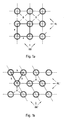
- a triangular division If the tube rows and the tube layers are not aligned perpendicular to one another, this is called a triangular division.
- the tube centers of three adjacent tubes lie on the corners of a triangle, which may be isosceles but does not have to. If the side lengths of such a triangle are known, then the arrangement of the tubes in the register is also clearly defined, as if the side lengths of a square or rectangular area formed by the tube centers of adjacent tubes are predetermined in the case of square or rectangular divisions. Within a register, the distances concerning the respective division do not change. Registers with a square pitch and a triangular pitch are for better clarity in the Fig. 1a and 1b shown schematically.
- a heat exchanger may have one or more registers.
- the heat exchangers are used for heat exchange between different fluids, which may be liquid or gaseous.
- the fluid flowing through the register is referred to hereinafter as Nutzfluid and the fluid flowing through the tubes of the register referred to as heat transfer fluid.
- the useful fluid of a heat exchanger can be used, if required, as the heat transfer fluid of another heat exchanger.
- the useful fluid is treated after leaving the one heat exchanger and before entering the other heat exchanger as a heat transfer fluid regularly in a further process stage, such as condensation or deposition of interfering components.
- heat exchangers which are operated in the so-called cross-flow.
- the heat exchanger or at least one register is divided into two separate regions, so that flow in the two areas of different Nutzfluide to the tubes of the register.
- the flow direction of the Nutzfluide can be opposite.
- the heat transfer fluid within the tubes of the register in this case transports heat from one area of the register to the other area of the register, so that the one useful fluid gives off heat to the other use fluid.
- the used fluids can be one and the same fluid flow at two different points in time during a process-related process, for example for the treatment, conditioning and / or purification of the fluid flow.
- the heat exchangers or registers are used, for example, to cool or heat up a useful fluid in the form of a flue gas which arises during the combustion of a fuel.
- the heat exchangers For example, integrated into an emission control system.
- a flue gas scrubber in the form of a gas cooler while provided for the heating of flue gases heat exchanger can be followed by a flue gas scrubber to dry the flue gas.
- the temperature of the flue gas is raised to a higher temperature level in order to avoid condensing of individual components in downstream system parts.
- both gas cooler and gas dryer can be provided.
- Interfering components can have a considerable amount of interfering components. These interfering components are predominantly particles, for example in the form of dusts.
- interfering components can also be liquids, such as, for example, condensate or washing liquid entrained at the outlet of an upstream scrubber. The liquid is distributed over a large number of individual droplets.
- the condensate can be an acid or an aqueous acidic solution, in particular in the treatment of flue gases.
- the condensate as other liquids and / or solids can be introduced into the heat exchanger. But the condensate can also be formed only in the heat exchanger or in at least one register of the heat exchanger by a drop in temperature.
- the aggregate state of the interfering component differs from that of the useful fluid.
- the interfering components in a working fluid such as a flue gas, may be homogeneous, such as of the same substance, or heterogeneously composed of different substances.
- the interfering components can get stuck in the heat exchanger, in particular in at least one of the registers of the heat exchanger and accumulate there. Therefore, registers operated with service fluids with a higher concentration of interfering components should be periodically cleaned to avoid clogging of the register between individual tubes. Furthermore, it may also be undesirable if the interfering components are simply discharged with the Nutzfluid.
- flushing medium For cleaning, a larger amount of flushing medium is often supplied to the working fluid prior to entry into the register during operation, which is then entrained by the flow of the Nutzfluids and carried through the register. This usually happens in more or less regular, predetermined time intervals.
- the flushing medium can also be introduced evenly distributed within the tube bundle of the heat exchanger.
- the flushing medium which is usually water, should in any case come into contact with the accumulating in the register interfering components and carry them out together with the flushing medium, in particular in the flow direction of the Nutzfluids from the register.
- the register has the least possible tendency to accumulate interfering components and at the same time be well cleaned
- the register is constructed in such a way that the useful fluid has a high flow velocity between the tube layers which are regularly aligned parallel to the outflow direction of the useful fluid. This is achieved in particular by the fact that the registers of tubes with relative are constructed large diameters, which are arranged at large distances from each other. Ultimately arise between the pipe layers broad flow paths, which oppose the Nutzfluid a low flow resistance and can be flowed through by the Nutzfluid quickly.
- the present invention is therefore the object of a register and a heat exchanger of the type mentioned in such a way and further that when operating with Nutzfluiden with high levels of interfering components such as flue gases, the tendency to fouling and blocking is reduced and thus in a continuous Operation longer service life can be achieved.
- the present invention has recognized that, contrary to the prior teaching regarding the design of heat exchanger registers, the symmetrical arrangement of the tubes in the registers is disadvantageous in terms of undesirable accumulation of interfering components in continuous operation.
- this knowledge is used to move away from a highly symmetrical structure of the register and to create a register which is deliberately constructed asymmetrically to a certain extent.
- This certain asymmetry is created by providing flow lanes with significantly different lane widths in the register.
- a significantly different lane width in this context means that the lane widths differ significantly from one another in such a way that the flow resistance in the flow lanes differ significantly from one another.
- the difference between the widths of the lanes depends on the working fluid and the process conditions and therefore can not be exactly quantified.
- a small lane width is so small that the Nutzfluidströmung is delayed such that there is a significant decrease in entrained by the Nutzfluid Störkomponenten.
- the flow velocity is so high that the delay of the Nutzfluidströmung can be compensated in the areas of narrow lane width.
- This preferably means that at constant pressure loss, the same volume flow of useful fluid flows through the register as in a symmetrical arrangement of the tubes in the register. Depending on the available pressure loss, it does not depend on an exact adherence to said relationship. In addition, it is assumed in this pressure loss consideration of an unpolluted register. Otherwise, in a conventional register due to the higher deposits of interfering components the Nutzfluidströmung be the same pressure loss significantly lower than in the previously described register.
- the large lane width may be more than 1.10, more than 1.25, more than 1.5, more than 2.0, more than 2.5 or more than 3.0 times as wide depending on the application as appropriate the narrow lane width. In principle, therefore, a significant difference between the large and the narrow lane width is preferred. However, it may simultaneously or alternatively be an obstacle to the flow distribution within the register if the differences between the large lane width and the narrow lane width are too clear, so that may form ineffective dead zones in which there is no flow. Too large differences in the lane widths may alternatively or additionally reduce the heat transfer area as the sum of the lateral surfaces of the tubes of the register, which may adversely affect the heat to be transferred per volume of the register. The large lane width should therefore not be more than 5, not more than 4, not more than 3 or not more than 2 times as wide as the narrow lane width, if necessary.
- the interfering components in the calm zones in the register ie in the area of the small widths of the lane, can drop in the direction of gravity, a situation arises Removing the Nutzfluids of interfering components.
- the interference components can thereby sink completely downwards, wherein the sunken interference components are preferably drawn off in some way in order to prevent accumulation.
- a partial flow of the interfering components entering the register will fall in the direction of gravity and be withdrawn at the bottom of the register, while the other part will be discharged from the register with the working fluid in the direction of flow of the useful fluid.
- Corresponding heat exchangers are preferably designed as gas coolers. If the heat exchanger is designed as a gas dryer in which the Nutzfluid is heated, and if the interfering components with the Nutzfluid are registered droplets, which are entrained, for example, from an upstream scrubber or mist eliminator, it is preferred that the spurious components substantially completely down dissipate and withdraw the Nutzfluidstrom after its entry into the register in this way quickly.
- the interfering components can thus optionally have a homogeneous or an inhomogeneous composition, wherein the interfering components also consist of different materials and may, if necessary, have different states of aggregation.
- the heat transfer fluid flowing through the tubes may, if necessary, be a so-called heat transfer medium provided specifically for the transport of heat. In particular, water and oils are considered.
- the heat transfer fluid may also be a process medium, which, like the used fluid, preferably also exists anyway and preferably has to be heated or cooled anyway.
- the heat transfer fluid may for example also be a flue gas.
- Heat transfer fluid and working fluid may optionally be gaseous and / or liquid.
- the Nutzfluid is a flue gas, more preferably, a flue gas to be cooled or aufloomendes.
- the register is used for indirect heat exchange, since the heat transfer fluid and the Nutzfluid not come into direct contact with each other, but the heat is transferred only through the pipe walls.
- the register has a plurality of tube layers and tube rows, wherein the tubes of a row of tubes are part of different tube layers and vice versa.
- the pipe layers extend substantially in the flow direction of the Nutzfluids, while the rows of tubes obliquely, possibly transverse, aligned with the flow direction of the Nutzfluids.
- the tubes of at least one tube layer can in each case be arranged in alignment with one another in the direction of flow of the useful fluid or else offset relative to one another, while the tubes of at least one row of tubes are aligned transversely to the flow direction of the useful fluid one behind the other or else arranged offset to one another.
- the width of a flow alley always determines itself in a row of pipes, by the distance between two adjacent, the flow path limiting tubes.
- the lane width of at least one flow lane of a register from tube row to tube row can vary or even remain constant.
- the narrow and wide sections of row of tubes to row of tubes in the flow direction of the Nutzfluids can be arranged uniformly one behind the other.
- a narrow section follows a further section in the flow direction in the following row of tubes, or that the width of the narrow and wide sections varies in successive rows of tubes as well as in one and the same row of tubes.
- any plurality of rows of pipes, pipe layers and / or flow paths may be meant.
- it may be an overwhelming majority, with a share exceeding 50%.
- all or substantially all rows of tubes, pipe layers and / or flow paths may also be meant.
- a first embodiment of the register can be provided for a simple production and a simple design of the register that at least individual Flow paths of the register in the flow direction of the Nutzfluids successive rows of tubes of the register have a constant lane width.
- the lane width of the same flow path thus does not change during the transition from one row of tubes to the next row of tubes in the flow direction.
- the register thus constructed has flow paths which are formed identically in successive rows of tubes. In this case, these flow paths in the direction of the respective tubes have a constant or even a varying width of the lane.
- at least one flow lane has a constant lane width along all tube rows of the register.
- the corresponding flow lane does not necessarily have to have a constant lane width in the direction of the tubes, but may possibly have both narrow and wide sections with correspondingly small and large lane widths alternately.
- each tube in at least one row of tubes each tube is fixed to a holding element which is rod-shaped and extends substantially along the tube layers.
- the influence of the flow can be minimized.
- the rod-shaped holding elements of a row of tubes disturb the sinking of the interference components only minimally.
- the at least one retaining element can also be curved in the shape of a lattice or, in particular, around tubes adjacent to the retaining element.
- the holding elements interfere with this Lowering of interference components as little as possible and allow, if necessary, in addition a certain mobility of the tubes, especially if they are arranged flexibly.
- materials for the production of the holding element are quite generally metals, ceramics or plastics in question, wherein the metals may have a corrosion protection, which is formed, if necessary, by a plastic sheath.
- Fluoroplastics are particularly suitable as plastic for the retaining element or the jacket.
- exactly one pipe layer is fixed to at least one retaining element of the register, while exactly two adjacent pipe layers are fixed to at least one other retaining element. This is particularly useful when using pipes with different diameters in at least one row of pipes. Then, for example, a pipe layer with pipes of a large diameter can alternately be fastened to a separate retaining element, while adjacent thereto two pipe layers with pipes of smaller diameter are fixed to a common retaining element arranged between the pipe layers.
- the holding elements can also serve to position the tubes of at least one row of tubes or of the entire register.
- the holding elements have spacers for spacing the tubes fixed to the holding elements between the tubes fixed to the holding elements at least one row of tubes.
- the holding elements are formed directly as spacers. They then have between the respective pipes to be spaced to a width corresponding to the desired distance of the tubes, without the need for another component.
- the holding elements do not interfere too much with the flow of the useful fluid through the register, it is advantageous if the holding elements are arranged either in flow lanes with a small lane width and / or in narrow sections of the respective flow lane of at least one row of tubes.
- the tubes in these flow paths and / or sections in any case a small distance from the adjacent tubes, so that a material-saving fixation of the tubes can be achieved.
- the retaining elements disturb the sinking of interfering components in calmed zones only slightly, since the holding elements are arranged laterally on the tubes.
- the retaining element can also be arranged in the flow paths with a large lane width and / or in wide sections. Then, on a holding element settling interfering components are easily removed and do not accumulate so much during operation.
- the holding element is then preferably aligned along a flow lane with a wide lane width and extends in this flow lane along a pipe layer delimiting the flow lane. In this case, holding sections of the holding element can then be provided which connect the tubes of this tube layer to the holding element.
- the tubes of the register can in at least one row of tubes in at least one flow alley with a narrow lane width or in a narrow Section may be provided a purge line for supplying flushing medium.
- the flushing line extends substantially in the direction of the pipe layers and / or in the direction the flow paths, which preferably corresponds to the same direction.
- a purge line is provided.
- a flushing line may be provided in the narrow sections of the flow lanes in flow lanes with a varying lane width on a common plane. Wide sections of flow passages of the register can, if necessary, manage without flushing line.
- the rinse lines can be designed as spacers for spacing the rinse line of adjacent tubes of the at least one row of tubes. This is achieved structurally simply in that the flushing lines have a diameter which corresponds to the preferred distance of the adjacent tubes in the region of the respective flushing line.
- the flushing lines can also each in the flow alley with the small lane width and / or the narrow section the flow alley be arranged because the flushing liquid can be selectively supplied to the calmed zones, the flow is not affected in the flow lanes with large lanes widths and the pipes are already close to each other in said flow paths and / or said sections.
- At least one holding element may be formed simultaneously as flushing line or vice versa.
- the at least one retaining element has a substantially closed profile, which can be flowed through by the flushing medium, wherein the flushing medium can escape through a series of openings from the corresponding profile.
- At least one pipe layer is aligned at least in sections obliquely and / or curved with respect to the direction of flow of the. Register by the Nutzfluid. This has the consequence that the free flow path for the Nutzfluid opposite the direction of flow of the register is inclined.
- the Nutzfluid as such is preferably deflected, in the direction of the free flow lane.
- the spurious components which preferably have a higher density, are exposed to a higher inertia influence and are less strongly or hardly deflected.
- the tubes of a tube layer are preferably arranged offset from each other, so that the interference components as needed in the further flow against a tube further downstream in the direction of flow bounce tube row or preferably against a further downstream in the direction of flow pipe of a flow path defining pipe layer.
- the flow rate of the Nutzfluids is reduced, so that the bouncing against a pipe noise components can easily get down in the direction of gravity.
- the tubes arranged one behind the other in the flow direction are each offset only by a part of the width of the lane.
- the tubes are then not set to gap with each other, which is unfavorable in terms of flow, but are always in the defined by the front row of tubes flow in it. It can then expand on the other side of the flow alley in the same or similar extent, so that the flow path has a total along at least one pipe layer substantially a constant width of the lane.
- the flow path is slightly inclined to the flow direction of the register. This arrangement has the effect that jamming components entrained by the working fluid, in particular in the form of droplets, do not readily flow through the register, but with a higher probability strike against one of the tubes of the register projecting in the direction of flow into the flow lane.
- At least two pipe layers define a flow path with an inlet-side opening and an outlet-side opening for the useful fluid between them such that the inlet-side opening in the direction of flow of the user fluid with respect to the register does not overlap with the exit opening.
- An interfering component such as in the form of a droplet, can then not, or at least hardly, be carried straight through in the direction of flow of the register through this. Rather, there is a very high probability that the droplets will hit pipes of one of the pipe layers and be deposited accordingly. Thus, a Entfrachtung the Nutzfluids about entrained liquid is easily possible.
- the inlet-side opening is the lane width of the flow lane formed in the direction of flow of the useful fluid in the foremost row of tubes, while the outlet-side opening is analogous to the lane width of the flow lane of the rearmost row of tubes.
- the register instead of the register as such, reference may also be made to a partial region of the register, so that further tubes or rows of tubes may be provided on the inlet side and / or outlet side.
- flow paths are arranged with constant lane widths. This is easy and inexpensive to realize, especially with straight pipes. Nevertheless, an asymmetry can, if necessary, be created in a row of pipes by providing flow paths there which have widths of the lane varying along the longitudinal extension of the pipes, that is to say preferably wide sections and narrow sections.
- the register becomes even simpler and less expensive if at least the flow paths located in a row of pipes each have a constant width of the lane.
- the lane width is constant in the direction of the longitudinal extent of the tubes.
- Preferably the lane widths in all pipe rows of the register are constant. This allows a very simple and therefore cost-effective design of the register, wherein the tubes are formed in particular straight.
- At least one flow channel is arranged with alternating narrow sections and wide sections. This makes it possible, for example, to build a register with the desired asymmetry by a combination of flow lanes with a constant lane width and flow lanes with a varying lane width in a row of tubes or in different rows of tubes.
- the flow paths are understandably provided in the longitudinal extension of the tubes with a constant or varying width of the lane.
- all flow paths are each equipped with varying lane widths in at least one row of tubes, alternating in each individual flow lane of the row of tubes narrow sections and wide sections.
- Another, possibly additional way to provide an imbalance in the register, without the register is random and thus complicated to build and interpret, could consist in at least one row of tubes in a direction perpendicular to the tubes of the row of tubes narrow sections and wide sections adjacent Flow lanes next to each other to arrange alternately to each other.
- the register thus constructed has flow paths which, in successive rows of tubes, have a shape which varies in the direction of flow of the useful fluid and preferably alternates.
- the shape of the flow paths thus varies and allows a non-symmetrical structure of the register, which follows at the same time clear rules and thus can be easily manufactured and calculated for the purpose of interpretation.
- One way to summarize areas with a large lane width and a small lane width in a register is that at least individual tubes at least one row of tubes are partially part of a first layer of pipe and partially part of a second layer of pipe.
- the corresponding tubes thus extend in sections in the one tube layer and in sections in at least one other tube layer. This arises, for example, when adjacent tubes of a row of tubes crossed with each other be, with a pipe from one pipe layer of the tube row to the other adjacent tube layer of the tube row is performed, while the adjacent tube is guided from the adjacent other tube layer to a tube layer.
- a corresponding crossing of the tubes can be provided in a series of tubes in a flow alley simple or repetitive multiply.
- tubes of any pipe layers in a row of pipes can be crossed with each other or any pipes of a pipe layer can be crossed with each other. It is also possible to intersect pipes that belong on the one hand to different rows of pipes and on the other hand to different pipe layers. For the sake of simplicity, however, it is provided that adjacent tubes of a row of tubes extend in sections in immediately adjacent tube layers of the tube row.
- a simple, regular but not symmetrical construction of the register can be achieved if a flow path defined by a first pipe layer and a second pipe layer has a plurality of narrow sections and / or wide sections in at least one row of pipes.
- a flow path defined by a first pipe layer and a second pipe layer has a plurality of narrow sections and / or wide sections in at least one row of pipes.
- exclusively wide sections exclusively narrow sections or wide and narrow sections alternately, and preferably alternately provided. Only narrow portions occur when the tubes of the two flow path defining tube layers of a row of tubes along the longitudinal direction of the tubes always alternately with each other are crossed and between the crossing points only narrow flow cross sections remain free.
- the wide sections are then preferably provided in adjacent flow paths of the same row of tubes. For this purpose, it is then sufficient if necessary, if the adjacent tubes of the row of tubes are rectilinear, because the crossed tubes ensure that the forming lane width of the adjacent flow lane varies.
- an asymmetry of the register can be provided in a simple manner by at least individual tubes of at least one row of tubes, preferably several times, being crossed with one another along the longitudinal extent of the tubes.
- a relatively regular structure of the register with a large number of wide sections and narrow sections results when substantially all tubes of at least one row of tubes, preferably several times, are crossed along the longitudinal extent of the respective tubes with adjacent tubes.
- the crossing points of crossed tubes can lie on the same planes perpendicular to the longitudinal extent of the tubes, as the crossing points of the adjacent crossed tubes.
- the crossing points of crossed tubes can lie on a first row of planes, while the points of intersection of the adjacent tubes of the tube row lie on a second row of planes, which are also aligned perpendicular to the longitudinal extent of the tubes.
- each two crossed tubes always lie alternately on the first row of planes and the second row of planes. Adjacent crossed tubes are thus always arranged alternately offset in the longitudinal direction of the tubes by the distance of the planes of different rows against each other.
- Varying widths and thus a targeted asymmetry of the register can be structurally particularly simple achieve that are provided in at least one row of tubes and / or in at least one tube layer tubes with significantly different tube diameter.
- pipes with different diameters can be arranged alternately and in relation to one another in the at least one row of pipes or pipe layers so that the flow paths with different widths of the lanes result therefrom.
- each tube adjacent at least one row of tubes with a larger diameter each two tubes of at least one row of tubes is arranged with a small diameter.
- two thin tubes follows a thick tube, which then again follow two thin tubes, etc.
- the tubes are made of a plastic, preferably of a fluorine plastic, in particular of perfluoroalkoxy (PFA). This achieves high resistance to corrosive media.
- the tubes can be made of metal, preferably made of a correspondingly resistant, in particular made of a corrosion-resistant metal.
- the tubes may be flexible in order to be able to easily arrange the tubes in the desired alignment with one another. This is especially the case when individual tubes should be crossed with each other. The necessary flexibility can be ensured by the said plastic material of the tubes readily.
- the register may also have both flexible and rigid tubes. This is useful, for example, if the rigid tubes are to contribute to the stability of the register.
- the tubes with a larger diameter are rigid and the tubes with a smaller diameter are flexible.
- rectilinear tubes of a register are rigid and the bent tubes of the same register are flexible.
- the flexible tubes are made of a plastic and the rigid tubes are made of metal.
- the tubes of at least two adjacent tube layers with staggered tubes can be brought very close to each other, if necessary even overlapping. Then remain between the corresponding tubes, if at all, only very narrow gaps transverse to the flow direction of the Nutzfluids.
- the tubes ultimately together form a so-called tube disc, which reflects the sound waves to a high degree.
- at least one corresponding pipe disk can be provided in that the pipes of at least one pipe layer are brought so close together that no or only very small spaces remain between the pipes of this pipe layer. In order to achieve this, either in the at least one pipe layer, the number of pipes is significantly increased compared to other pipe layers or their diameter significantly increased compared to other tubes of the register.
- the tubes of the at least one tube layer for the reflection of the sound can be rigid, for example made of metal.
- a heat exchanger with at least one register according to claim 13, characterized in that the at least one register is a register according to one of claims 1 to 12.
- a transversely oriented to the flow direction barrier to protect the pipes from abrasion is provided by entrained by the Nutzfluid Störkomponenten.
- the interfering components are in particular particles, such as dusts or the like.
- the barrier is preferably applied where local peaks of the concentration of interfering components occur. This is due to the influence of gravity on the spurious components regularly at the bottom of the heat exchanger of the case.
- the barrier is therefore preferably provided in the direction of gravity lower end of the register.
- the barrier forms a gap with the bottom of the heat exchanger.
- the Nutzfluid flows at an increased speed and can thus entrain on the bottom of the heat exchanger accumulating and / or preferably sunk in the calm zones down towards the ground Stör components and carry out in this way from the heat exchanger.-This ultimately leads to a Entfrachtung with the Nutzfluid.
- the height of the free gap corresponds at most approximately to the minimum distance between the lower end of the register and the bottom of the heat exchanger, so that the lower end of the register is not exposed to increased abrasion by the interfering components.
- the register is preferably as a hung U-tube heat exchanger coil with pipe bends on formed in the direction of gravity lower end of the register.
- the lane width is maximum.
- this at least one flow path widens downward to improve the removal of jamming components from the register, even if this results in the lane width of adjacent flow lanes being correspondingly lower, so that the width of the register can remain constant overall.
- the lane width is substantially zero in at least one row of pipes at least in a flow lane with a small lane width.
- the corresponding adjacent tubes of at least one row of tubes can thereby, preferably almost, abut each other.
- the above-described structural features of the register of the heat exchanger can in principle be combined with one another in any desired manner. This is especially true in the various ways described, deviating from a symmetrical structure of a register of a heat exchanger. It can therefore be made, for example, in different rows of tubes and / or pipe layers of different types of asymmetrical design and / or different dimensions of a particular unbalanced design use. It could also be in one and the same Tube row and / or pipe layer of different such configurations use made. In order to keep the complexity with regard to the manufacture and the design of the register low, it is nevertheless appropriate if in each case one row of tubes and / or one tube layer use is made of only one embodiment, which leads to an overall asymmetrical structure of the register. In other words, then different pipe layers and / or rows of pipes structurally different from each other.
- the register described above is particularly well suited due to its design for heating and / or cooling gas containing interfering components, in particular flue gas.
- the interfering components may be particles, condensate and / or entrained liquid. Therefore, the effects of the register come into play especially when it is before and / or downstream of a flue gas scrubber (claim 17). Then the flue gas is heated and / or cooled.
- a detail of a heat exchanger 1 is shown, which has a register 2 with parallel aligned pipes 3.
- the register 2 perpendicular to the flow direction S of the Nutzfluids a series of successively arranged rows of tubes 4, which form mutually parallel pipe layers 5 in the flow direction S of the Nutzfluids.
- the individual tubes 3 of each tube layer 5 are arranged in alignment in the flow direction S of the Nutzfluids one behind the other.
- each flow lane 6,6 'in each row of tubes 4 a lane width 7,7', which is determined by the distance between adjacent tubes 3.
- the lane width 7,7 'of each flow path 6,6' in the flow direction S of the Nutzfluids constant.
- the lane width 7,7 'of the flow paths 6,6' therefore does not change from tube row 4 to tube row 4 of the register 2.
- the lane width is 7,7 'aligned in the illustrated embodiment, each perpendicular to the flow direction S of the Nutzfluids.
- flow paths 6,6 ' alternate with a large lane width 7' and a small lane width 7. Due to the larger lane width 7 'is in the corresponding flow paths 6', a higher flow rate of the Nutzfluids, while due to the lower Gassenbreite 7 sets a lower flow velocity of the Nutzfluids in the remaining flow paths 6.
- the in the FIGS. 2 and 3 3 shown tubes are each paired in pairs and fixed to a common support member 8, which is rod-shaped and extends parallel to the adjacent pipe layers 5, ie along the flow path 6, with small lane width 7.
- the holding elements 8 are held in the illustrated plane of the register 2 on a transversely extending to the register 9 suspension.
- the holding elements 8 have spacers 10, on each of which two adjacent sides of two pipes 3 different pipe layers 5 are in abutment.
- For fixing each two adjacent tubes 3 different pipe layers 5 on the support member 8 is a tube 3 encompassing ring element 11.
- Fig. 4 is another detail of the register 2 according to FIGS. 2 and 3 shown, in Fig. 4 a view corresponding to the Fig. 2 is shown, however, which shows a section in a region in which flushing lines 12 are provided for flushing and thus for removing interference components from the register 2.
- the purge lines 12 may be arranged differently high in the register. In any case, at least some of the purge lines 12 are arranged relatively high in the register 2. Furthermore, the purge lines 12 are provided only in each second flow path 6. In this case, the purge lines 12 extend in It is also possible, although not shown in detail, that the flushing lines 12 are fastened to holding elements 8 substantially along the entire flow paths 6 through the register 2.
- the purge lines 12 are provided in the narrower flow paths 6 and also have an outer diameter which coincides with the smaller lane width 7 of these flow paths 6 substantially.
- the flushing lines 12 have openings over their length, not shown, from which a flushing medium, such as water, specifically exit can.
- a flushing medium such as water
- the lane width 7,7 'of the respective flow path 6,6' does not vary over the height of the illustrated register 2, but remains constant. This is achieved in particular by the fact that the tubes 3 run parallel to one another.
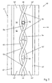
- Fig. 5 is a register 2 'shown schematically in a section perpendicular to the longitudinal extent of the tubes 3.
- the pipe layers 5 ' are not parallel, but obliquely aligned to the inflow direction AS of the Nutzfuids with respect to the register 2'.
- This is going through a small offset of the rows of tubes 4 'following each other in the direction of flow AS is achieved by a large part of the lane width of the flow lane 6 ", thus forming flow lanes 6" where the inlet-side openings 14 of the flow lanes 6 "do not for the useful fluid overlap more with the outlet-side openings 15 of the flow paths 6 ".
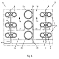
- register 22 of a heat exchanger 21 differs from that in the Fig. 2 to 3 Register 2 shown by the fact that pipes are installed 3,23 different diameters.
- 5.25 exclusively tubes 3.23 are provided with identical diameter in each pipe layer.
- the pipe layers 5,25 are also so assembled to the register 22 that follow two pipe layers 5 with pipes 3 small diameter always a pipe layer 25 of a large diameter and this always two pipe layers 5 with pipes 3 small diameter.
- the two adjacent pipe layers 5 with pipes 3 of smaller diameter are held by a common holding element 8 which extends along the flow path 6 formed by these two pipe layers 5 and is also formed rod-shaped.
- each tube layer 25 with tubes 23 of a large diameter is held by a separate holding element 28, which is arranged laterally to the tube layer 25. Therefore, this holding element 28 also comes without separate spacers.
- the two adjacent pipe layers 5 with tubes 3 of a smaller diameter are in the illustrated embodiment, as already to the Fig. 2 to 4 described constructed. The same applies in principle for the arrangement of the purge line in the flow paths 6 with a small lane width 7, so the flow paths 6 between the pipe layers 5 with tubes 3 of a small diameter. That in the Fig. 6 shown register 22 has exclusively rectilinear tubes 3.23. It could also be used in any case partly curved pipes to build the register.
- register 42 of a heat exchanger 41 is similar to that in the Fig. 2 shown register 2, only the foremost row of tubes 44 shown, since the other rows of tubes 44 are arranged in alignment with the front row of tubes 44.
- the peculiarity of in the Fig. 7 represented register 42 in comparison to the register 2 according to the Fig. 2 to 4 is that the tubes 43 are alternately part of a first pipe layer 45 and a second pipe layer 45 'of the common pipe row 44.
- the tubes 43 cross each other in the transition from the first tube layer 45 to the second tube layer 45 'and vice versa.
- a flow lane 46 with narrow sections 54 ie smaller lane widths 47, is formed.
- Some of the narrow portions 54 have one Spacer 50 or a purge line 52 on.
- the purge line 52 has the same outer diameter as the spacer 50, so that the purge line 52 holds the two pairs crossed tubes 43 at the same time to each other at the desired distance.
- the illustrated crossed tubes 43 are rigid, so that between two points of intersection 53 of the tubes 43 not in any case a means must be provided, which contributes to the spacing of the tubes 43.
- a means which contributes to the spacing of the tubes 43.
- Such means would preferably be provided between each two adjacent crossing points of a flow, so that the tubes permanently occupy the desired position.
- the flow lanes 46 'adjacent to the two crossed tubes 43 have varying lane widths 47'.
- the flow paths 46 ' are at the level of the intersection points 53 widest and mid-height between the intersection points 53 narrowest.
- the flow channels 46 'adjoining the crossed tubes 43 which are delimited by the adjacent rectilinear tubes 43' of the tube row 44, again alternately have narrow sections 54 'and further sections 55 over their height.
- register 42,62 alternate pairs crossed tubes 43,63,63 'and rectilinear tubes 43', 63 "in a row of tubes 44,64 from each other.
- register 82 has only pairs crossed tubes 83.
- the points of intersection 93 of the pairs of crossed tubes 83 in any case of one row of tubes 84 lie in common planes 96 parallel to the flow direction.
- the paired crossed tubes 83 each define a flow path 86 'therebetween having only narrow portions 94' with smaller lane widths 87 ", which need not be identical to the narrow portions 94 'of the respective adjacent flow lanes 86.
- the points of intersection of adjacent tubes could also lie on different planes.
- the points of intersection of two tubes crossed with one another in the longitudinal extent of the tubes and / or the register lie substantially, in particular centrally, between the points of intersection of the adjacent crossed tubes, in particular on both sides of the tube row.
- the crossing points of these adjacent to both sides of the row of tubes, each pairwise crossed tubes are then preferably on common levels, especially with the crossing points of the next but one another in pairs crossed tubes of at least one row of tubes.
- a corresponding arrangement has the consequence that the flow path between each two pairs crossed pipes over the flow path height has a relatively uniform lane width. According to a corresponding embodiment, the corresponding flow path would assume a substantially serpentine shape.
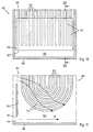
- the bottom portion of a heat exchanger 101 is shown with U-shaped tubes 103.
- the U-shaped tubes 103 of the register 102 are suspended in the heat exchanger 101 in the direction of gravity, so that the tube curves 117 of the U-shaped tubes 103 point in the direction of the bottom 118 of the heat exchanger 101.
- Between the curved tubes 103 and the bottom 118 of the heat exchanger 101 remains a gap 119 through which the working fluid can flow.
- a barrier 120 which is shown in the form of a plate and extends in a plane perpendicular to the flow direction S of the useful fluid in the illustrated embodiment.
- the barrier 120 is arranged such that between the bottom 118 of the heat exchanger 101 and the lower edge 121 of the barrier 120, a gap 119 is formed, through which the useful fluid flows at an increased speed and in the bottom area separated entrainment components, such as particles entrains, without This can lead to an increased abrasion at the register 102 in the region of the pipe bends 117.
- This increased flow rate of the Nutzfluids in the gap 122 below the pipe bends 117 is schematically in the sectional view of Fig. 11 shown.
- the stagnation of the Nutzfluids in the flow direction S in front of the barrier 120 also results in increased flow velocities in the overflow of the barrier 120 through the Nutzfluid, which thus flows at an increased flow rate through the region of the tube curvatures 117 and there interference components, from the top of the flow of Nutzfluids have sunk, removed.
- the flow lanes can be widened with large lane widths in the region of the lower end of the register where the pipe bends are located, whereby the flow lanes are narrowed locally with small lane widths. This can have a positive effect on the removal of the interfering components from the register.
Abstract
Description
Die Erfindung betrifft ein Register für den indirekten Wärmeaustausch zwischen einem Störkomponenten aufweisenden Nutzfluid, insbesondere einem Rauchgas, und einem Wärmeträgerfluid in einem Wärmeaustauscher, mit einer Mehrzahl von Rohren zum Durchleiten des Wärmeträgerfluids, wobei die Rohre in mehreren Rohrlagen sowie mehreren Rohrreihen angeordnet sind, wobei die Rohrlagen und die Rohrreihen quer zueinander verlaufen und wobei die Rohrlagen mehrere Strömungsgassen zum Durchströmen des Nutzfluids definieren. Ferner betrifft die Erfindung einen Wärmeaustauscher mit wenigstens einem Register sowie eine Verwendung des Registers. Ein Register nach dem Oberbegriff des Anspruchs 1 wird in
Register eines Wärmeaustauschers umfassen eine Mehrzahl von Rohren und werden auch als Rohrbündel bezeichnet. Die Rohre bilden parallel zueinander angeordnete Rohrlagen. Auf diese Weise werden zwischen den Rohrlagen Strömungsgassen für das Durchströmen des Nutzfluids gebildet. Quer zu den Rohrlagen bilden die Rohre des Registers sogenannte Rohrreihen, die ebenfalls parallel zueinander angeordnet sind. In einem Register eines Wärmeaustauschers sind die Abstände zwischen den Rohrreihen ebenso konstant wie die Abstände zwischen den Rohrlagen. Ein Register ist daher in sich symmetrisch aufgebaut. Zur Beschreibung des Aufbaus eines Registers, also der genauen Anordnung der Rohre untereinander, dient die sogenannte Teilung.Registers of a heat exchanger include a plurality of tubes and are also referred to as tube bundles. The tubes form mutually parallel pipe layers. In this way, flow paths for the passage of the Nutzfluids be formed between the pipe layers. Transverse to the pipe layers form the tubes of the register so-called rows of tubes, which are also arranged parallel to each other. In a register of a heat exchanger, the distances between the rows of tubes are just as constant as the distances between the tube layers. A register is therefore symmetrical in itself. To describe the structure of a register, so the exact arrangement of the tubes with each other, serves the so-called division.
Sind die Rohreihen und die Rohrlagen senkrecht zueinander ausgerichtet, so spricht man von einer quadratischen Teilung, wenn die Rohrreihen und die Rohrlagen gleich weit voneinander beabstandet sind. Ist dies nicht der Fall, spricht man von einer Rechteckteilung. Zur genauen Definition der Anordnung der Rohre wird neben der Art der Teilung noch der Abstand der Rohrmittelpunkte zwischen zwei Rohrreihen und zwei Rohrlagen angegeben. Bei einer quadratischen Teilung reicht dementsprechend die Angabe eines Abstands aus.If the rows of tubes and the tube layers are oriented perpendicular to one another, this is called a square division if the tube rows and the tube layers are equidistant from each other are spaced. If this is not the case, it is called a rectangular division. For a precise definition of the arrangement of the pipes, the distance between the center of the pipe between two pipe rows and two pipe layers is specified in addition to the type of division. In the case of a quadratic division, it is sufficient to specify a distance.
Sind die Rohrreihen und die Rohrlagen nicht senkrecht zueinander ausgerichtet, so spricht man von einer Dreiecksteilung. Die Rohrmittelpunkte von drei zueinander benachbarten Rohren liegen dabei auf den Ecken eines Dreiecks, das gleichschenklig sein kann aber nicht muss. Sind die Seitenlängen eines solches Dreiecks bekannt, so ist die Anordnung der Rohre im Register ebenso eindeutig festgelegt, wie wenn bei quadratischen bzw. Rechtecksteilungen die Seitenlängen eines durch die Rohrmittelpunkte benachbarter Rohre gebildeten Quadrats bzw. Rechtsecks vorgegeben sind. Innerhalb eines Registers ändern sich die die jeweilige Teilung betreffenden Abstände nicht. Register mit einer quadratischen Teilung und einer Dreiecksteilung sind der besseren Anschaulichkeit halber in den
Derartige Register aufweisende Wärmeaustauscher sind in unterschiedlichen Ausführungen aus der Praxis bekannt und werden insbesondere als Rohrbündelwärmeaustauscher bezeichnet. Ein Wärmeaustauscher kann dabei ein oder mehrere Register aufweisen. Die Wärmeaustauscher werden zum Wärmeaustausch zwischen unterschiedlichen Fluiden eingesetzt, die flüssig oder auch gasförmig sein können. Das durch das Register strömende Fluid wird dabei im Folgenden als Nutzfluid und das durch die Rohre des Registers strömende Fluid als Wärmeträgerfluid bezeichnet.Such registers having heat exchangers are known in different embodiments from practice and are referred to in particular as a tube bundle heat exchanger. A heat exchanger may have one or more registers. The heat exchangers are used for heat exchange between different fluids, which may be liquid or gaseous. The fluid flowing through the register is referred to hereinafter as Nutzfluid and the fluid flowing through the tubes of the register referred to as heat transfer fluid.
Kommen in einem Prozess mehrere Wärmeaustauscher zum Einsatz, kann das Nutzfluid eines wärmeaustauschers bedarfsweise als Wärmeträgerfluid eines anderen Wärmeaustauschers verwendet werden. Das Nutzfluid wird dabei nach dem Verlassen des einen Wärmeaustauschers und vor dem Eintritt in den anderen Wärmeaustauscher als Wärmeträgerfluid regelmäßig in einer weiteren Prozessstufe, wie einer Kondensation oder einer Abscheidung von Störkomponenten, behandelt.If several heat exchangers are used in a single process, the useful fluid of a heat exchanger can be used, if required, as the heat transfer fluid of another heat exchanger. The useful fluid is treated after leaving the one heat exchanger and before entering the other heat exchanger as a heat transfer fluid regularly in a further process stage, such as condensation or deposition of interfering components.
Es sind auch Wärmeaustauscher bekannt, die im sogenannten Kreuzstrom betrieben werden. Dabei ist der Wärmeaustauscher bzw. wenigstens ein Register in zwei voneinander getrennte Bereiche unterteilt, so dass in den beiden Bereichen unterschiedliche Nutzfluide um die Rohre des Registers strömen. Die Strömungsrichtung der Nutzfluide kann dabei entgegengesetzt sein. Das Wärmeträgerfluid innerhalb der Rohre des Registers transportiert in diesem Fall Wärme von einem Bereich des Registers in den anderen Bereich des Registers, so dass das eine Nutzfluid Wärme an das andere Nutzfluid abgibt. Bei den Nutzfluiden kann es sich um ein und denselben Fluidstrom zu zwei unterschiedlichen Zeitpunkten während eines verfahrenstechnischen Prozesses etwa zur Aufbereitung, Konditionierung und/oder Reinigung des Fluidstroms handeln.There are also known heat exchangers, which are operated in the so-called cross-flow. In this case, the heat exchanger or at least one register is divided into two separate regions, so that flow in the two areas of different Nutzfluide to the tubes of the register. The flow direction of the Nutzfluide can be opposite. The heat transfer fluid within the tubes of the register in this case transports heat from one area of the register to the other area of the register, so that the one useful fluid gives off heat to the other use fluid. The used fluids can be one and the same fluid flow at two different points in time during a process-related process, for example for the treatment, conditioning and / or purification of the fluid flow.
Die Wärmeaustauscher bzw. Register werden beispielsweise dazu verwendet, ein Nutzfluid in Form eines Rauchgases, das bei der Verbrennung eines Brennstoffs entsteht, abzukühlen oder aufzuheizen. Zu diesem Zweck werden die Wärmeaustauscher beispielsweise in eine Abgasreinigungsanlage integriert. Zur Kühlung von Rauchgasen ausgebildete Wärmeaustauscher sind beispielsweise einem Rauchgaswäscher in Form eines Gaskühlers vorgeschaltet, während für das Aufheizen von Rauchgasen vorgesehene Wärmeaustauscher einem Rauchgaswäscher nachgeschaltet sein können, um das Rauchgas zu trocknen. Dabei wird die Temperatur des Rauchgases auf ein höheres Temperaturniveau angehoben, um ein Auskondensieren einzelner Komponenten in nachgeschalteten Anlagenteilen zu vermeiden. Bei Abgasreinigungsanlagen können sowohl Gaskühler als auch Gastrockner vorgesehen sein.The heat exchangers or registers are used, for example, to cool or heat up a useful fluid in the form of a flue gas which arises during the combustion of a fuel. For this purpose, the heat exchangers For example, integrated into an emission control system. For the cooling of flue gases formed heat exchangers are upstream, for example, a flue gas scrubber in the form of a gas cooler, while provided for the heating of flue gases heat exchanger can be followed by a flue gas scrubber to dry the flue gas. The temperature of the flue gas is raised to a higher temperature level in order to avoid condensing of individual components in downstream system parts. In exhaust gas purification systems both gas cooler and gas dryer can be provided.
Rauchgase können, wie auch andere Medien, eine nicht unerhebliche Menge an Störkomponenten aufweisen. Bei diesen Störkomponenten handelt es sich vorwiegend um Partikel, etwa in Form von Stäuben. Störkomponenten können aber auch Flüssigkeiten, wie beispielsweise Kondensat oder bei Austritt eines vorgeschalteten Wäschers mitgerissene Waschflüssigkeit, sein. Die Flüssigkeit verteilt sich dabei auf eine Vielzahl einzelner Tröpfchen. Bei dem Kondensat kann es sich, insbesondere bei der Behandlung von Rauchgasen, um eine Säure bzw. eine wässrige saure Lösung handeln. Zudem kann das Kondensat wie andere Flüssigkeiten und/oder Feststoffe in den Wärmeaustauscher eingebracht werden. Das Kondensat kann aber auch erst im Wärmeaustauscher bzw. im wenigstens einem Register des Wärmeaustauschers durch ein Absinken der Temperatur gebildet werden. Ganz allgemein unterscheidet sich dabei der Aggregatszustand der Störkomponente von dem des Nutzfluids. Die Störkomponenten in einem Nutzfluid, wie etwa einem Rauchgas, können homogen, etwa aus der gleichen Substanz, oder heterogen aus unterschiedlichen Substanzen zusammengesetzt sein.Flue gases, like other media, can have a considerable amount of interfering components. These interfering components are predominantly particles, for example in the form of dusts. However, interfering components can also be liquids, such as, for example, condensate or washing liquid entrained at the outlet of an upstream scrubber. The liquid is distributed over a large number of individual droplets. The condensate can be an acid or an aqueous acidic solution, in particular in the treatment of flue gases. In addition, the condensate as other liquids and / or solids can be introduced into the heat exchanger. But the condensate can also be formed only in the heat exchanger or in at least one register of the heat exchanger by a drop in temperature. In general, the aggregate state of the interfering component differs from that of the useful fluid. The interfering components in a working fluid, such as a flue gas, may be homogeneous, such as of the same substance, or heterogeneously composed of different substances.
Die Störkomponenten können im Wärmeaustauscher, insbesondere in wenigstens einem der Register des wärmeaustauschers hängenbleiben und sich dort ansammeln. Daher sind Register, die mit Nutzfluiden mit einer größeren Konzentration an Störkomponenten betrieben werden, in regelmäßigen Abständen zu reinigen, damit es nicht zu einem Zusetzen des Registers zwischen einzelnen Rohren kommt. Ferner kann es aber auch unerwünscht sein, wenn die Störkomponenten einfach mit dem Nutzfluid ausgetragen werden.The interfering components can get stuck in the heat exchanger, in particular in at least one of the registers of the heat exchanger and accumulate there. Therefore, registers operated with service fluids with a higher concentration of interfering components should be periodically cleaned to avoid clogging of the register between individual tubes. Furthermore, it may also be undesirable if the interfering components are simply discharged with the Nutzfluid.
Zur Reinigung wird häufig dem Nutzfluid vor dem Eintritt in das Register während des Betriebs eine größeren Menge Spülmedium zugeführt, das dann von der Strömung des Nutzfluids mitgerissen und durch das Register hindurchgetragen wird. Dies geschieht meist in mehr oder weniger regelmäßigen, vorgegebenen Zeitabständen. Das Spülmedium kann bedarfsweise-auch gleichmäßig verteilt innerhalb des Rohrbündels des Wärmeaustauschers eingebracht werden. Das Spülmedium, bei dem es sich meist um Wasser handelt, soll dabei in jedem Fall mit den sich im Register ansammelnden Störkomponenten in Kontakt kommen und diese gemeinsam mit dem Spülmedium, insbesondere in Strömungsrichtung des Nutzfluids, aus dem Register austragen.For cleaning, a larger amount of flushing medium is often supplied to the working fluid prior to entry into the register during operation, which is then entrained by the flow of the Nutzfluids and carried through the register. This usually happens in more or less regular, predetermined time intervals. If desired, the flushing medium can also be introduced evenly distributed within the tube bundle of the heat exchanger. The flushing medium, which is usually water, should in any case come into contact with the accumulating in the register interfering components and carry them out together with the flushing medium, in particular in the flow direction of the Nutzfluids from the register.
Damit das Register möglichst wenig dazu neigt, dass sich Störkomponenten ansammeln und gleichzeitig gut gereinigt werden kann, ist das Register derart aufgebaut, dass zwischen den Rohrlagen, die regelmäßig parallel zur Ausströmrichtung des Nutzfluids ausgerichtet sind, das Nutzfluid eine hohe Strömungsgeschwindigkeit aufweist. Dies wird insbesondere dadurch erreicht, dass die Register aus Rohren mit relativ großen Durchmessern aufgebaut sind, die dafür in großen Abständen zueinander angeordnet sind. Letztlich entstehen so zwischen den Rohrlagen breite Strömungsgassen, die dem Nutzfluid einen geringen Strömungswiderstand entgegensetzen und so vom Nutzfluid schnell durchströmt werden können.So that the register has the least possible tendency to accumulate interfering components and at the same time be well cleaned, the register is constructed in such a way that the useful fluid has a high flow velocity between the tube layers which are regularly aligned parallel to the outflow direction of the useful fluid. This is achieved in particular by the fact that the registers of tubes with relative are constructed large diameters, which are arranged at large distances from each other. Ultimately arise between the pipe layers broad flow paths, which oppose the Nutzfluid a low flow resistance and can be flowed through by the Nutzfluid quickly.
Dennoch hat sich in der Praxis gezeigt, dass sich die Störkomponenten im Register in hohem Maße ansammeln können, was zum teilweise Verblocken oder Zusetzen des Registers, beispielsweise im Strömungsschatten zwischen den Rohren einer Rohrlage, führen kann. Dies hat beispielsweise zur Folge, dass kontinuierlich betriebene Anlagen vorzeitig abgefahren werden müssen, um das Register zu warten bzw. manuell zu reinigen. Dies führt bei aushärtenden Störkomponenten durch die schwierige, zum Teil mechanische Abreinigung häufig zu Beschädigungen an den Rohren und/oder deren Korrosionsschutz. Dadurch kommt es letztlich zu unerwünschten Rohrausfällen.Nevertheless, it has been found in practice that the spurious components in the register can accumulate to a high degree, which can lead to partial blocking or clogging of the register, for example in the flow shadow between the tubes of a tube layer. This has the consequence, for example, that plants operated continuously have to be driven off prematurely in order to maintain the register or to clean it manually. This leads to hardening interfering components by the difficult, sometimes mechanical cleaning often damage the pipes and / or their corrosion protection. This ultimately leads to unwanted tube failures.
Der vorliegenden Erfindung liegt daher die Aufgabe zugrunde, ein Register und einen Wärmeaustauscher der eingangs genannten Art derart auszugestalten und weiterzubilden, dass beim Betrieb mit Nutzfluiden mit hohen Anteilen an Störkomponenten, wie etwa Rauchgasen, die Neigung zum Verschmutzen und Verblocken verringert ist und somit im kontinuierlichen Betrieb längere Standzeiten erreicht werden.The present invention is therefore the object of a register and a heat exchanger of the type mentioned in such a way and further that when operating with Nutzfluiden with high levels of interfering components such as flue gases, the tendency to fouling and blocking is reduced and thus in a continuous Operation longer service life can be achieved.
Die zuvor genannte Aufgabe wird erfindungsgemäß von einem Register mit den Merkmalen des Anspruchs 1 gelöst.The aforementioned object is achieved by a register with the features of claim 1.
Die vorliegende Erfindung hat erkannt, dass entgegen der bisherigen Lehre hinsichtlich des Designs von Wärmetauscherregistern die symmetrische Anordnung der Rohre in den Registern hinsichtlich einer unerwünschten Ansammlung von Störkomponenten im kontinuierlichen Betrieb nachteilig ist.The present invention has recognized that, contrary to the prior teaching regarding the design of heat exchanger registers, the symmetrical arrangement of the tubes in the registers is disadvantageous in terms of undesirable accumulation of interfering components in continuous operation.
Erfindungsgemäß wird aufgrund dieser Erkenntnis von einem höchst symmetrischen Aufbau des Registers abgerückt und ein Register geschaffen, das bewusst in einem gewissen Maß unsymmetrisch aufgebaut ist. Diese gewisse Unsymmetrie wird geschaffen, indem im Register Strömungsgassen mit erheblich unterschiedlicher Gassenbreite vorgesehen werden. Eine erheblich unterschiedliche Gassenbreite bedeutet in diesem Zusammenhang, dass die Gassenbreiten sich derart nennenswert voneinander unterscheiden, dass sich die Strömungswiderstände in den Strömungsgassen deutlich voneinander unterscheiden. Der Unterschied zwischen den Gassenbreiten ist dabei vom Nutzfluid und den Prozessbedingungen abhängig und demnach nicht exakt zu quantifizieren. Alternativ kann aber auch vorgesehen sein, dass wenigstens eine Strömungsgasse verschiedene Abschnitte mit unterschiedlichen Gassenbreiten aufweist, wobei die Unterschiede in dem zuvor beschriebenen Sinne nennenswert sind. Bedarfsweise ist auch eine Kombination der zuvor beschriebenen Alternativen möglich.According to the invention, this knowledge is used to move away from a highly symmetrical structure of the register and to create a register which is deliberately constructed asymmetrically to a certain extent. This certain asymmetry is created by providing flow lanes with significantly different lane widths in the register. A significantly different lane width in this context means that the lane widths differ significantly from one another in such a way that the flow resistance in the flow lanes differ significantly from one another. The difference between the widths of the lanes depends on the working fluid and the process conditions and therefore can not be exactly quantified. Alternatively, however, it can also be provided that at least one flow lane has different sections with different lane widths, the differences in the previously described Meaning are significant. If necessary, a combination of the alternatives described above is possible.
Große Gassenbreiten sorgen dafür, dass der dem Nutzfluid entgegenwirkende Strömungswiderstand ab- und die Strömungsgeschwindigkeit des Nutzfluids gleichzeitig zunimmt. Bei diesem Vergleich wird selbstverständlich von einem konstanten Druckverlust der Nutzfluidströmung beim Durchtritt durch das Register ausgegangen. Bei geringen Gassenbreiten steigt der Strömungswiderstand dagegen an, so dass in diesen Bereichen des Registers eine geringere Strömungsgeschwindigkeit herrscht. Erfindungsgemäß werden also ganz bewusst Bereiche mit unterschiedlichen Strömungsgeschwindigkeiten im Register herbeigeführt.Large lane widths ensure that the flow of fluid counteracting the useful fluid decreases and the flow rate of the useful fluid simultaneously increases. In this comparison, of course, is assumed by a constant pressure drop of the Nutzfluidströmung when passing through the register. On the other hand, in the case of narrow lane widths, the flow resistance increases, so that a lower flow velocity prevails in these regions of the register. Thus, according to the invention, areas with different flow velocities are deliberately brought about in the register.
Eine geringe Gassenbreite ist dabei so gering, dass die Nutzfluidströmung derart verzögert wird, dass es zu einem nennenswerten Absinken von vom Nutzfluid mitgeführten Störkomponenten kommt. In den Bereichen einer großen Gassenbreite ist die Strömungsgeschwindigkeit dagegen so hoch, dass die Verzögerung der Nutzfluidströmung in den Bereichen geringer Gassenbreite ausgeglichen werden kann. Dies bedeutet vorzugsweise, dass bei konstantem Druckverlust der gleiche Volumenstrom an Nutzfluid durch das Register strömt wie bei einer symmetrischen Anordnung der Rohre im Register. Je nach dem zur Verfügung stehenden Druckverlust kommt es hier nicht auf eine exakte Einhaltung des genannten Zusammenhangs an. Zudem wird bei dieser Druckverlustbetrachtung von einem unverschmutzten Register ausgegangen. Andernfalls kann bei einem konventionellen Register infolge der höheren Ablagerungen an Störkomponenten die Nutzfluidströmung bei gleichem Druckverlust deutlich geringer sein als bei dem zuvor beschriebenen Register.A small lane width is so small that the Nutzfluidströmung is delayed such that there is a significant decrease in entrained by the Nutzfluid Störkomponenten. In contrast, in the areas of a large lane width, the flow velocity is so high that the delay of the Nutzfluidströmung can be compensated in the areas of narrow lane width. This preferably means that at constant pressure loss, the same volume flow of useful fluid flows through the register as in a symmetrical arrangement of the tubes in the register. Depending on the available pressure loss, it does not depend on an exact adherence to said relationship. In addition, it is assumed in this pressure loss consideration of an unpolluted register. Otherwise, in a conventional register due to the higher deposits of interfering components the Nutzfluidströmung be the same pressure loss significantly lower than in the previously described register.
Die große Gassenbreite kann dabei je nach Anwendungsfall zweckmäßiger Weise mehr als 1,10, mehr als 1,25, mehr als 1,5, mehr als 2,0, mehr als 2,5 oder mehr als 3,0 mal so breit sein wie die geringe Gassenbreite. Grundsätzlich ist also ein nennenswerter Unterschied zwischen der großen und der geringen Gassenbreite bevorzugt. Es kann gleichzeitig oder alternativ für die Strömungsverteilung innerhalb des Registers jedoch hinderlich sein, wenn die Unterschiede zwischen der großen Gassenbreite und der geringen Gassenbreite zu deutlich sind, so dass sich unter Umständen nicht wirksame Totzonen bilden, in denen keine Strömung vorliegt. Bei zu großen Unterschieden hinsichtlich der Gassenbreiten kann sich alternativ oder zusätzlich die Wärmeübertragungsfläche als Summe der Mantelflächen der Rohre des Registers stark verringern, was sich ungünstig auf die pro Volumen des Registers zu übertragende Wärme auswirken kann. Die große Gassenbreite sollte daher bedarfsweise nicht mehr als 5, nicht mehr als 4, nicht mehr als 3 oder nicht mehr als 2 mal so breit wie die geringe Gassenbreite sein.The large lane width may be more than 1.10, more than 1.25, more than 1.5, more than 2.0, more than 2.5 or more than 3.0 times as wide depending on the application as appropriate the narrow lane width. In principle, therefore, a significant difference between the large and the narrow lane width is preferred. However, it may simultaneously or alternatively be an obstacle to the flow distribution within the register if the differences between the large lane width and the narrow lane width are too clear, so that may form ineffective dead zones in which there is no flow. Too large differences in the lane widths may alternatively or additionally reduce the heat transfer area as the sum of the lateral surfaces of the tubes of the register, which may adversely affect the heat to be transferred per volume of the register. The large lane width should therefore not be more than 5, not more than 4, not more than 3 or not more than 2 times as wide as the narrow lane width, if necessary.
Innerhalb eines Registers können auch unterschiedlich dimensionierte große Gassenbreiten und/oder unterschiedlich dimensionierte geringe Gassenbreiten vorgesehen sein. Auf diese Weise wird ein hohes Maß an Unsymmetrie und damit eine hohe Anzahl unterschiedlicher Strömungszustände innerhalb des wenigstens einen Registers eines Wärmeaustauschers geschaffen.Within a register also different sized large lane widths and / or different sized narrow lane widths can be provided. In this way, a high degree of asymmetry and thus a large number of different flow states are created within the at least one register of a heat exchanger.
Die vorstehenden Ausführungen hinsichtlich der Dimension von großen und geringen Gassenbreiten trifft sowohl auf Strömungsgassen einzelner Rohrreihen zu, bei denen zwischen zwei benachbarten Rohren eine konstante Gassenbreite vorgesehen ist, als auch auf solche Rohrreihen, bei denen zwischen zwei benachbarten Rohren abschnittsweise eine große Gassenbreite und abschnittsweise eine geringe Gassenbreite vorgesehen ist.The foregoing with regard to the dimension of large and small lane widths applies both to flow lanes of individual rows of tubes, where a constant lane width is provided between two adjacent tubes, as well as on such rows of tubes, where between two adjacent tubes sections a large lane width and sections one small lane width is provided.
Bedarfsweise können im Register Bereiche bereitgestellt werden, in denen die Strömung des Nutzfluids fast vollständig zum Erliegen kommt. Zwingend ist dies jedoch nicht. Die Strömungsgeschwindigkeit sollte in diesen beruhigten Zonen jedoch so weit herabgesetzt sein, dass die Störkomponenten bzw. zu Reinigungszwecken eingebrachte Spülmedien nennenswert in Richtung der Schwerkraft absinken können. Allerdings sollte die Strömung auch nicht völlig zum Erliegen kommen, weil dann auch keine Strömungskomponenten mehr in die beruhigten Zonen eintreten und dort nach unten sinken können. Auch sollte die Strömungsgeschwindigkeit nicht so herabgesetzt werden, dass in den Bereichen mit einer großen Gassenbreite die Strömungsgassen zu breit werden, was sich negativ auf den Wärmeaustausch auswirken kann. Die Strömungsgeschwindigkeit sollte in den Bereichen mit einer großen Gassenbreite auch nicht so deutlich ansteigen müssen, um noch den erforderlichen Volumenstrom durch das Register zu transportieren, so dass hierfür ein stark erhöhter Druckverlust in Kauf genommen werden muss.If required, areas can be provided in the register in which the flow of the useful fluid almost completely stops. However, this is not mandatory. However, the flow velocity in these calmed zones should be reduced so far that the spurious components or flushing media introduced for cleaning purposes can drop appreciably in the direction of gravity. However, the flow should not come to a complete standstill, because then no flow components more enter the calm zones and can sink down there. Also, the flow rate should not be lowered so that in the areas with a large lane width, the flow paths are too wide, which can adversely affect the heat exchange. The flow velocity should not increase so much in the areas with a large width of the lane in order to transport the required volume flow through the register, so that a greatly increased pressure loss must be accepted.
Dadurch, dass die Störkomponenten in den beruhigten Zonen im Register, also im Bereich der geringen Gassenbreiten, in Richtung der Schwerkraft absinken können, kommt es zu einem Entfrachten des Nutzfluids von Störkomponenten. Die Störkomponenten können dabei vollständig nach unten absinken, wobei die herabgesunkenen Störkomponenten vorzugsweise auf irgendeine Art und Weise abgezogen werden, um eine Anhäufung zu verhindern. Insbesondere wird ein Teilstrom der in das Register eintretenden Störkomponenten in Richtung der Schwerkraft absinken und am Boden des Registers abgezogen, während der andere Teil mit dem Nutzfluid in Strömungsrichtung des Nutzfluids aus dem Register ausgetragen wird.Due to the fact that the interfering components in the calm zones in the register, ie in the area of the small widths of the lane, can drop in the direction of gravity, a situation arises Removing the Nutzfluids of interfering components. The interference components can thereby sink completely downwards, wherein the sunken interference components are preferably drawn off in some way in order to prevent accumulation. In particular, a partial flow of the interfering components entering the register will fall in the direction of gravity and be withdrawn at the bottom of the register, while the other part will be discharged from the register with the working fluid in the direction of flow of the useful fluid.
Handelt es sich bei-den Störkomponenten um Partikel oder Kondensat, kann es ausreichend sein, wenn diese Störkomponenten teilweise in beruhigten Zonen absinken und weiter unten wieder in Zonen größerer Strömungsgeschwindigkeit eintreten, um dann mit dem Nutzfluidstrom das Register zu verlassen. Ein Zusetzen des Registers kann so ggf. bereits vermieden werden. Entsprechende-Wärmeaustauscher sind vorzugsweise als Gaskühler ausgebildet. Wenn der Wärmeaustauscher als ein Gastrockner ausgebildet ist, in dem das Nutzfluid aufgeheizt wird, und wenn die Störkomponenten mit dem Nutzfluid eingetragene Tröpfchen sind, die beispielsweise aus einem vorgeschalteten Gaswäscher bzw. Tropfenabscheider mitgerissen werden, ist es bevorzugt, die Störkomponenten im Wesentlichen vollständig nach unten abzuführen und dem Nutzfluidstrom nach dessen Eintritt in das Register auf diese Weise zügig zu entziehen. Dies ist energetisch bevorzugt, weil die nach unten abgeschiedenen Tröpfchen im Register nicht verdampft werden müssen, um die nötige Trockenheit des Nutzfluids beim Austreten aus dem Register zu erreichen. Die nötige Trockenheit des Nutzfluids ist dann erreicht, wenn dessen Temperatur weit genug oberhalb des Taupunkts liegt und/oder das Nutzfluid jedenfalls keine Tröpfchen mehr aufweist.If the interfering components are particulates or condensate, it may be sufficient for these interfering components to sink partially into calmed zones and then back into zones of greater flow velocity, and then leave the register with the useful fluid stream. A clogging of the register can thus possibly already be avoided. Corresponding heat exchangers are preferably designed as gas coolers. If the heat exchanger is designed as a gas dryer in which the Nutzfluid is heated, and if the interfering components with the Nutzfluid are registered droplets, which are entrained, for example, from an upstream scrubber or mist eliminator, it is preferred that the spurious components substantially completely down dissipate and withdraw the Nutzfluidstrom after its entry into the register in this way quickly. This is energetically preferred because the downwardly deposited droplets in the register need not be vaporized to achieve the necessary dryness of the working fluid as it exits the register. The necessary dryness of the Nutzfluids is reached when the Temperature is far enough above the dew point and / or the Nutzfluid in any case has no more droplets.
Bei Rohrbündel-Wärmeaustauschern aus dem Stand der Technik sammelt sich der Anteil der Störkomponenten, der nicht mit der Nutzgasströmung wieder ausgetragen wird, im wenigstens einen Register des Wärmeaustauschers etwa in Form von Anhaftungen bzw. Anbackungen an, was ein vorzeitiges Abfahren und Reinigen des Registers erforderlich macht.In shell-and-tube heat exchangers of the prior art, the proportion of interfering components which is not discharged again with the useful gas flow accumulates in the at least one register of the heat exchanger, for example in the form of adhesions or caking, which necessitates premature shutdown and cleaning of the register power.
Aufgrund der Tatsache, dass beim erfindungsgemäßen Register in den weiten Abschnitten mit einer größeren Gassenbreite hohe Strömungsgeschwindigkeiten des Nutzfluids erzielt werden, kommt es innerhalb des Wärmeaustauschers vorzugsweise zu Turbulenzen, die letztlich wiederum dazu führen, dass Störkomponenten aus den Bereichen höherer Strömungsgeschwindigkeit in Bereiche langsamerer Strömungsgeschwindigkeit gelangen und dort nach unten absinken können. Störkomponenten können auch von dem schnell strömenden Nutzfluid von beruhigter Zone zu beruhigter Zone gelangen und dabei schrittweise nach unten absinken oder nur teilweise absinken und, etwa an tieferer Stelle, über Gassen großer Gassenbreite aus dem Register ausgetragen werden.Due to the fact that in the register according to the invention high flow velocities of the Nutzfluids be achieved in the wide sections with a larger lane width, it is preferably within the heat exchanger turbulence, which in turn ultimately lead to interference components from the areas of higher flow rate reach areas of slower flow rate and fall down there. Interfering components can also pass from the rapidly flowing working fluid from the calmed zone to the calmed zone and gradually drop downwards or only partially fall off and, at a lower point, be discharged from the register via lanes of large lane width.
Unter Störkomponenten werden die Mehrzahl von vom Nutzfluid mitgeführten Partikeln und/oder Tröpfchen verstanden. Die Störkomponenten können also wahlweise eine homogene oder eine inhomogene Zusammensetzung aufweisen, wobei die Störkomponenten auch aus unterschiedlichen Materialen bestehen und bedarfsweise unterschiedliche Aggregatzustände aufweisen können.Under Störkomponenten the majority of the Nutzfluid entrained particles and / or droplets are understood. The interfering components can thus optionally have a homogeneous or an inhomogeneous composition, wherein the interfering components also consist of different materials and may, if necessary, have different states of aggregation.
Bei dem durch die Rohre strömenden Wärmeträgerfluid kann es sich bedarfsweise um ein speziell für den Wärmetransport vorgesehenes, sogenanntes Wärmeträgermedium handeln. Dabei kommen insbesondere Wasser und Öle in Betracht. Alternativ kann es sich bei dem Wärmeträgerfluid aber auch um ein Prozessmedium handeln, das vorzugsweise ebenso wie das Nutzfluid ebenfalls ohnehin vorhanden ist und vorzugsweise ohnehin aufgeheizt oder abgekühlt werden muss. Das Wärmeträgerfluid kann beispielweise auch ein Rauchgas sein. Wärmeträgerfluid und Nutzfluid können wahlweise gasförmig und/oder flüssig sein. Bevorzugt ist das Nutzfluid ein Rauchgas, weiter vorzugsweise, ein abzukühlendes oder aufzuheizendes Rauchgas.The heat transfer fluid flowing through the tubes may, if necessary, be a so-called heat transfer medium provided specifically for the transport of heat. In particular, water and oils are considered. Alternatively, the heat transfer fluid may also be a process medium, which, like the used fluid, preferably also exists anyway and preferably has to be heated or cooled anyway. The heat transfer fluid may for example also be a flue gas. Heat transfer fluid and working fluid may optionally be gaseous and / or liquid. Preferably, the Nutzfluid is a flue gas, more preferably, a flue gas to be cooled or aufheizendes.
Das Register dient dem indirekten Wärmeaustausch, da das Wärmeträgerfluid und das Nutzfluid nicht in einen direkten Kontakt miteinander kommen, sondern die Wärme lediglich über die Rohrwandungen übertragen wird.The register is used for indirect heat exchange, since the heat transfer fluid and the Nutzfluid not come into direct contact with each other, but the heat is transferred only through the pipe walls.
Das Register weist eine Mehrzahl von Rohrlagen und Rohrreihen auf, wobei die Rohre einer Rohrreihe Teil unterschiedlicher Rohrlagen sind und umgekehrt. Dabei erstrecken sich die Rohrlagen im Wesentlichen in Strömungsrichtung des Nutzfluids, während die Rohrreihen schräg, ggf. quer, zur Strömungsrichtung des Nutzfluids ausgerichtet verlaufen.The register has a plurality of tube layers and tube rows, wherein the tubes of a row of tubes are part of different tube layers and vice versa. In this case, the pipe layers extend substantially in the flow direction of the Nutzfluids, while the rows of tubes obliquely, possibly transverse, aligned with the flow direction of the Nutzfluids.
Die Rohre wenigstens einer Rohrlage können dabei in Strömungsrichtung des Nutzfluids jeweils fluchtend hintereinander oder aber auch versetzt zueinander angeordnet sein, während die Rohre wenigstens einer Rohrreihe quer zur Strömungsrichtung des Nutzfluids jeweils fluchtend hintereinander oder aber auch versetzt zueinander angeordnet sind.The tubes of at least one tube layer can in each case be arranged in alignment with one another in the direction of flow of the useful fluid or else offset relative to one another, while the tubes of at least one row of tubes are aligned transversely to the flow direction of the useful fluid one behind the other or else arranged offset to one another.
Die Breite einer Strömungsgasse bestimmt sich dabei immer in einer Rohrreihe, und zwar durch den Abstand zweier benachbarter, die Strömungsgasse begrenzender Rohre. Damit kann die Gassenbreite wenigstens einer Strömungsgasse eines Registers von Rohrreihe zu Rohrreihe variieren oder aber auch konstant bleiben. In dem Fall, dass die Strömungsgasse in wenigstens einer Rohrreihe Abschnitte mit unterschiedlichen Gassenbreiten, also schmale und weite Abschnitte, aufweist, können die schmalen und weiten Abschnitte von Rohrreihe zu Rohrreihe in Strömungsrichtung des Nutzfluids gleichförmig hintereinander angeordnet sein. Es kann aber auch vorgesehen sein, dass einem schmalen Abschnitt in Strömungsrichtung ein weiter Abschnitt in der folgenden Rohrreihe folgt, oder dass die Gassenbreite der schmalen und der weiten Abschnitte in aufeinanderfolgenden Rohrreihen sowie auch in ein und derselben Rohrreihe variiert.The width of a flow alley always determines itself in a row of pipes, by the distance between two adjacent, the flow path limiting tubes. Thus, the lane width of at least one flow lane of a register from tube row to tube row can vary or even remain constant. In the event that the flow path in at least one row of tubes sections with different widths of the lanes, so narrow and wide sections, has, the narrow and wide sections of row of tubes to row of tubes in the flow direction of the Nutzfluids can be arranged uniformly one behind the other. However, it can also be provided that a narrow section follows a further section in the flow direction in the following row of tubes, or that the width of the narrow and wide sections varies in successive rows of tubes as well as in one and the same row of tubes.
Es versteht sich, dass, wenn vorliegend von wenigstens einer Rohrreihe, Rohrlage oder Strömungsgasse die Rede ist, auch eine beliebige Mehrzahl von Rohrreihen, Rohrlagen und/oder Strömungsgassen gemeint sein kann. Beispielsweise kann es sich um eine überwiegende Mehrzahl handeln, deren Anteil 50% übersteigt. Es können aber auch alle oder im Wesentlichen alle Rohrreihen, Rohrlagen und/oder Strömungsgassen gemeint sein.It is understood that, in the present case of at least one row of pipes, pipe layer or flow alley is mentioned, also any plurality of rows of pipes, pipe layers and / or flow paths may be meant. For example, it may be an overwhelming majority, with a share exceeding 50%. However, all or substantially all rows of tubes, pipe layers and / or flow paths may also be meant.
Bei einer ersten Ausgestaltung des Registers kann zu einer einfachen Fertigung und einer einfachen Auslegung des Registers vorgesehen sein, dass wenigstens einzelne Strömungsgassen des Registers in in Strömungsrichtung des Nutzfluids aufeinanderfolgenden Rohrreihen des Registers eine konstante Gassenbreite aufweisen. Die Gassenbreite einer gleichen Strömungsgasse verändert sich also beim Übergang von einer Rohrreihe zur in Strömungsrichtung nächsten Rohrreihe nicht. Mit anderen Worten weist das so aufgebaute Register Strömungsgassen auf, die in aufeinanderfolgenden Rohrreihen identisch ausgebildet sind. Dabei können diese Strömungsgassen in Richtung der jeweiligen Rohre eine konstante oder aber auch eine variierende Gassenbreite aufweisen. Vorzugsweise, weil leicht herzustellen, weist wenigstens eine Strömungsgasse entlang aller Rohrreihen des Registers eine konstante Gassenbreite auf. Entlang der Strömungsrichtung des Nutzfluids ändert sich die Gassenbreite der Strömungsgasse also nicht. Dabei muss die entsprechende Strömungsgasse aber nicht zwingend in Richtung der Rohre eine konstante Gassenbreite aufweisen, sondern kann evtl. alternierend sowohl schmale als auch weite Abschnitte mit entsprechend geringen und großen Gassenbreiten aufweisen.In a first embodiment of the register can be provided for a simple production and a simple design of the register that at least individual Flow paths of the register in the flow direction of the Nutzfluids successive rows of tubes of the register have a constant lane width. The lane width of the same flow path thus does not change during the transition from one row of tubes to the next row of tubes in the flow direction. In other words, the register thus constructed has flow paths which are formed identically in successive rows of tubes. In this case, these flow paths in the direction of the respective tubes have a constant or even a varying width of the lane. Preferably, because it is easy to manufacture, at least one flow lane has a constant lane width along all tube rows of the register. Along the flow direction of the Nutzfluids the lane width of the flow path does not change so. However, the corresponding flow lane does not necessarily have to have a constant lane width in the direction of the tubes, but may possibly have both narrow and wide sections with correspondingly small and large lane widths alternately.
Zur einfachen Fixierung der Rohre des Registers wird vorgesehen, dass in wenigstens einer Rohrreihe jedes Rohr an einem Halteelement fixiert ist, das stabförmig ausgebildet ist und sich im wesentlichen entlang der Rohrlagen erstreckt. Die Beeinflussung der Strömung kann so minimiert werden. Zudem stören die stabförmigen Halteelemente einer Rohrreihe das Absinken der Störkomponenten nur minimal.For easy fixation of the tubes of the register is provided that in at least one row of tubes each tube is fixed to a holding element which is rod-shaped and extends substantially along the tube layers. The influence of the flow can be minimized. In addition, the rod-shaped holding elements of a row of tubes disturb the sinking of the interference components only minimally.
Bedarfsweise kann das wenigstens eine Halteelement auch gitterförmig, oder, insbesondere um an das Halteelement angrenzende Rohre, gebogen sein. Die Halteelemente stören das Absinken von Störkomponenten möglichst wenig und erlauben bedarfsweise zusätzlich eine gewisse Beweglichkeit der Rohre, insbesondere wenn diese flexibel angeordnet sind. Als Werkstoffe zur Herstellung des Halteelements kommen ganz allgemein Metalle, Keramiken oder Kunststoffe in Frage, wobei die Metalle einen Korrosionsschutz aufweisen können, der bedarfsweise durch eine Kunststoffummantelung gebildet ist. Als Kunststoff für das Halteelement oder die Ummantelung bieten sich insbesondere Fluorkunststoffe an.If necessary, the at least one retaining element can also be curved in the shape of a lattice or, in particular, around tubes adjacent to the retaining element. The holding elements interfere with this Lowering of interference components as little as possible and allow, if necessary, in addition a certain mobility of the tubes, especially if they are arranged flexibly. As materials for the production of the holding element are quite generally metals, ceramics or plastics in question, wherein the metals may have a corrosion protection, which is formed, if necessary, by a plastic sheath. Fluoroplastics are particularly suitable as plastic for the retaining element or the jacket.
Eine konstruktiv einfache und zudem effektive Möglichkeit besteht-dabei darin, dass in wenigstens einer Rohrreihe in jeder zweiten Strömungsgasse jeweils ein Halteelement vorgesehen ist. Dann sind an jedem Halteelement die diesem benachbarten Rohre fixiert, und zwar vorzugsweise seitlich.A structurally simple and also effective possibility exists-in that in each case a holding element is provided in at least one row of tubes in each second flow alley. Then, the retaining elements of each of these adjacent tubes are fixed, preferably laterally.
Es kann alternativ aber auch vorgesehen sein, dass an wenigstens einem Halteelement des Registers genau eine Rohrlage fixiert ist, während an wenigstens einem anderen Halteelement genau zwei benachbarte Rohrlagen fixiert sind. Dies bietet sich insbesondere bei der Verwendung von Rohren mit unterschiedlichen Durchmessern in wenigstens einer Rohrreihe an. Dann kann beispielsweise abwechselnd eine Rohrlage mit Rohren eines großen Durchmessers an einem eigenen Halteelement befestigt sein, während benachbart dazu zwei Rohrlagen mit Rohren kleineren Durchmessers an einem gemeinsamen, zwischen den Rohrlagen angeordneten Halteelement fixiert sind.Alternatively, however, it can also be provided that exactly one pipe layer is fixed to at least one retaining element of the register, while exactly two adjacent pipe layers are fixed to at least one other retaining element. This is particularly useful when using pipes with different diameters in at least one row of pipes. Then, for example, a pipe layer with pipes of a large diameter can alternately be fastened to a separate retaining element, while adjacent thereto two pipe layers with pipes of smaller diameter are fixed to a common retaining element arranged between the pipe layers.
Dabei ist es für das freie Absinken der Störkomponenten von besonderem Vorteil, wenn die Halteelemente im Wesentlichen seitlich zu den durch das Haltelement gehaltenen Rohrlagen verlaufen.It is for the free sinking of the interfering components of particular advantage when the holding elements substantially extend laterally to the tube layers held by the holding element.
Zusätzlich zur Fixierung können die Haltelemente auch der Positionierung der Rohre wenigstens einer Rohrreihe oder des gesamten Registers dienen. Dazu kann vorgesehen sein, dass die Haltelemente zwischen den an den Halteelementen festgelegten Rohren wenigstens einer Rohrreihe Abstandshalter zur Beabstandung der an den Halteelementen festgelegten Rohre aufweisen. Alternativ oder zusätzlich kann aber auch vorgesehen sein, dass die Halteelemente direkt als Abstandshalter ausgebildet sind. Sie weisen dann zwischen den jeweils zu beabstandenden Rohren eine Breite auf, die dem gewünschten Abstand der Rohre entspricht, ohne dass es hierfür eines weiteren Bauteils bedarf.In addition to the fixation, the holding elements can also serve to position the tubes of at least one row of tubes or of the entire register. For this purpose, it may be provided that the holding elements have spacers for spacing the tubes fixed to the holding elements between the tubes fixed to the holding elements at least one row of tubes. Alternatively or additionally, however, it may also be provided that the holding elements are formed directly as spacers. They then have between the respective pipes to be spaced to a width corresponding to the desired distance of the tubes, without the need for another component.
Damit die Halteelemente die Strömung des Nutzfluids durch das Register nicht zu stark stören, ist es vorteilhaft, wenn die Halteelemente entweder in Strömungsgassen mit einer geringen Gassenbreite und/oder in schmalen Abschnitten der jeweiligen Strömungsgasse wenigstens einer Rohrreihe angeordnet sind. Zudem weisen die Rohre in diesen Strömungsgassen und/oder Abschnitten ohnehin einen geringen Abstand zu den einander benachbarten Rohren auf, so dass eine Material schonende Fixierung der Rohre erreicht werden kann. Dabei stören die Halteelemente das Absinken von Störkomponenten in beruhigten Zonen nur wenig, da die Halteelemente seitlich an den Rohren angeordnet sind.So that the holding elements do not interfere too much with the flow of the useful fluid through the register, it is advantageous if the holding elements are arranged either in flow lanes with a small lane width and / or in narrow sections of the respective flow lane of at least one row of tubes. In addition, the tubes in these flow paths and / or sections in any case a small distance from the adjacent tubes, so that a material-saving fixation of the tubes can be achieved. The retaining elements disturb the sinking of interfering components in calmed zones only slightly, since the holding elements are arranged laterally on the tubes.
In diesem Zusammenhang bietet es sich an, wenn die Halteelemente entlang der gesamten jeweiligen Rohrlagen jeweils in Strömungsgassen geringer Gassenbreite und/oder schmalen Abschnitten der Strömungsgassen vorgesehen sind. Dadurch werden die beschriebenen Vorteile in allen aufeinanderfolgenden Rohrreihen des Registers erreicht. Alternativ oder zusätzlich ist es aus konstruktiven Gesichtspunkten bevorzugt, wenn die Halteelemente stets in jeder zweiten Strömungsgasse vorgesehen sind. Dies ist ausreichend, um alle Rohre einer Rohrreihe und damit des Registers insgesamt zu fixieren.In this context, it makes sense if the holding elements along the entire respective pipe layers in each case in flow lanes narrow lane width and / or narrow sections of the flow paths are provided. This achieves the advantages described in all successive rows of tubes of the register. Alternatively or additionally, it is preferred from a constructional point of view if the retaining elements are always provided in every second flow lane. This is sufficient to fix all the tubes of a row of tubes and thus of the register as a whole.
Damit das wenigstens eine Halteelement das Herabsinken von Störkomponenten noch weniger beeinflusst, kann das Halteelement auch in den Strömungsgassen mit einer großen Gassenbreite und/oder in weiten Abschnitten angeordnet sein. Dann werden sich auf einem Halteelement absetzende Störkomponenten leichter entfernt und sammeln sich während des Betriebs nicht so stark an. Vorzugsweise ist dann das Halteelement entlang einer Strömungsgasse mit einer breiten Gassenbreite ausgerichtet und erstreckt sich in dieser Strömungsgasse entlang einer die Strömungsgasse begrenzenden Rohrlage. Dabei können dann Halteabschnitte des Halteelements vorgesehen sein, welche die Rohre dieser Rohrlage an das Halteelement anbinden.In order for the at least one retaining element to influence the lowering of interference components even less, the retaining element can also be arranged in the flow paths with a large lane width and / or in wide sections. Then, on a holding element settling interfering components are easily removed and do not accumulate so much during operation. The holding element is then preferably aligned along a flow lane with a wide lane width and extends in this flow lane along a pipe layer delimiting the flow lane. In this case, holding sections of the holding element can then be provided which connect the tubes of this tube layer to the holding element.
Sofern es trotz der Ausbildung von beruhigten Zonen und Zonen erhöhter Strömungsgeschwindigkeit des Nutzfuids durch die Anordnung der Rohre des Registers untereinander notwendig sein sollte, das Register im Betrieb zu reinigen, kann in wenigstens einer Rohrreihe in wenigstens einer Strömungsgasse mit einer geringen Gassenbreite oder in einem schmalen Abschnitt eine Spülleitung zur Zuführung von Spülmedium vorgesehen sein. Dabei erstreckt sich die Spülleitung im Wesentlichen in Richtung der Rohrlagen und/oder in Richtung der Strömungsgassen, was vorzugsweise derselben Richtung entspricht.If, despite the formation of calmed zones and zones of increased flow rate of the Nutzfuids by the arrangement of the tubes of the register should be necessary to clean the register in operation, can in at least one row of tubes in at least one flow alley with a narrow lane width or in a narrow Section may be provided a purge line for supplying flushing medium. In this case, the flushing line extends substantially in the direction of the pipe layers and / or in the direction the flow paths, which preferably corresponds to the same direction.
Besonders zweckmäßig ist es für die Reinigung des Registers, wenn in wenigstens einer Rohrreihe in jeder Strömungsgasse mit einer geringen Gassenbreite eine Spülleitung vorgesehen ist. Zusätzlich oder alternativ kann in Strömungsgassen mit einer variierenden Gassenbreite auf einer gemeinsamen Ebene jeweils eine Spülleitung in den schmalen Abschnitten der Strömungsgassen vorgesehen sein. Weite Abschnitte von Strömungsgassen des Registers können bedarfsweise ohne Spülleitung auskommen.It is particularly useful for the cleaning of the register when in at least one row of tubes in each flow alley with a small lane width a purge line is provided. Additionally or alternatively, in each case a flushing line may be provided in the narrow sections of the flow lanes in flow lanes with a varying lane width on a common plane. Wide sections of flow passages of the register can, if necessary, manage without flushing line.
Damit alle Bereiche des Registers, insbesondere die beruhigten Zonen des Registers, durch die Spülflüssigkeit gleichmäßig erreicht werden, ist es zweckmäßig, in wenigstens einer Rohrreihe eine Spülleitung in jeder zweiten Strömungsgasse vorzusehen. Dies gilt insbesondere dann, wenn die jeweils wenigstens zweiten Strömungsgassen eine geringe Gassenbreite und/oder eine variierende Gassenbreite aufweisen.So that all areas of the register, in particular the calmed zones of the register, are reached uniformly by the rinsing liquid, it is expedient to provide a rinsing line in every second flow line in at least one row of pipes. This applies in particular when the respective at least second flow paths have a small lane width and / or a varying lane width.
Neben der Zuführung von Spülflüssigkeit können die Spülleitungen als Abstandshalter zur Beabstandung der Spülleitung benachbarter Rohre der wenigstens einen Rohrreihe ausgebildet sein. Dies wird konstruktiv einfach dadurch erzielt, dass die Spülleitungen einen Durchmesser aufweisen, der dem bevorzugten Abstand der benachbarten Rohre im Bereich der jeweiligen Spülleitung entspricht.In addition to the supply of rinsing liquid, the rinse lines can be designed as spacers for spacing the rinse line of adjacent tubes of the at least one row of tubes. This is achieved structurally simply in that the flushing lines have a diameter which corresponds to the preferred distance of the adjacent tubes in the region of the respective flushing line.
Die Spülleitungen können zudem jeweils in der Strömungsgasse mit der geringen Gassenbreite und/oder dem schmalen Abschnitt der Strömungsgasse angeordnet sein, weil so die Spülflüssigkeit gezielt den beruhigten Zonen zugeführt werden kann, die Strömung in den Strömungsgassen mit großen Gassenbreiten nicht beeinträchtigt wird und die Rohre in den genannten Strömungsgassen und/oder den genannten Abschnitten ohnehin nahe beieinander liegen.The flushing lines can also each in the flow alley with the small lane width and / or the narrow section the flow alley be arranged because the flushing liquid can be selectively supplied to the calmed zones, the flow is not affected in the flow lanes with large lanes widths and the pipes are already close to each other in said flow paths and / or said sections.
Um den konstruktiven Aufwand für die Fertigung des Registers zu minimieren, kann wenigstens ein Halteelement gleichzeitig als Spülleitung ausgebildet sein oder umgekehrt. In diesem Zusammenhang bietet es sich an, wenn das wenigstens eine Halteelement ein im Wesentlichen geschlossenes Profil aufweist, das von dem Spülmedium durchströmt werden kann, wobei das Spülmedium durch eine Reihe von Öffnungen aus dem entsprechenden Profil austreten kann.In order to minimize the design effort for the production of the register, at least one holding element may be formed simultaneously as flushing line or vice versa. In this context, it makes sense if the at least one retaining element has a substantially closed profile, which can be flowed through by the flushing medium, wherein the flushing medium can escape through a series of openings from the corresponding profile.
Alternativ oder zusätzlich kann vorgesehen sein, dass wenigstens eine Rohrlage wenigstens abschnittsweise schräg und/oder gekrümmt in Bezug zur Anströmrichtung des.Registers durch das Nutzfluid ausgerichtet ist. Dies hat zur Folge, dass die freie Strömungsgasse für das Nutzfluid gegenüber der Anströmrichtung des Registers geneigt ist. Das Nutzfluid als solches wird dabei vorzugsweise abgelenkt, und zwar in Richtung der freien Strömungsgasse. Die Störkomponenten, welche vorzugsweise eine höhere Dichte aufweisen, sind jedoch einem höheren Trägheitseinfluss ausgesetzt und werden weniger stark bis kaum abgelenkt. Dabei sind vorzugsweise die Rohre einer Rohrlage gegeneinander versetzt angeordnet, so dass die Störkomponenten bedarfsweise im weiteren Strömungsverlauf gegen ein Rohr einer weiter in Strömungsrichtung hinten angeordneten Rohrreihe prallen oder vorzugsweise gegen ein in Strömungsrichtung weiter hinten angeordnetes Rohr einer die Strömungsgasse definierenden Rohrlage. Unmittelbar an den Rohren ist die Strömungsgeschwindigkeit des Nutzfluids herabgesetzt, so dass die gegen ein Rohr prallenden Störkomponenten leichter in Schwerkraftrichtung nach unten gelangen können.Alternatively or additionally, it can be provided that at least one pipe layer is aligned at least in sections obliquely and / or curved with respect to the direction of flow of the. Register by the Nutzfluid. This has the consequence that the free flow path for the Nutzfluid opposite the direction of flow of the register is inclined. The Nutzfluid as such is preferably deflected, in the direction of the free flow lane. However, the spurious components, which preferably have a higher density, are exposed to a higher inertia influence and are less strongly or hardly deflected. In this case, the tubes of a tube layer are preferably arranged offset from each other, so that the interference components as needed in the further flow against a tube further downstream in the direction of flow bounce tube row or preferably against a further downstream in the direction of flow pipe of a flow path defining pipe layer. Immediately to the Tubes, the flow rate of the Nutzfluids is reduced, so that the bouncing against a pipe noise components can easily get down in the direction of gravity.
Bevorzugt sind die in Strömungsrichtung hintereinander angeordneten Rohre jeweils nur um einen Teil der Gassenbreite versetzt. Die Rohre sind dann nicht auf Lücke zueinander gesetzt, was strömungstechnisch ungünstiger ist, sondern stehen immer weiter in die durch die vordere Rohrreihe definierte Strömungsgasse hinein. Es kann sich dann auf der anderen Seite die Strömungsgasse in gleichem oder ähnlichem Maße erweitern, so dass die Strömungsgasse insgesamt entlang wenigstens einer Rohrlage im Wesentlichen eine konstante Gassenbreite aufweist. Die Strömungsgasse ist jedoch etwas geneigt gegenüber der Anströmrichtung des Registers. Diese Anordnung hat den Effekt, dass vom Nutzfluid mitgerissene Störkomponenten, insbesondere in Form von Tröpfchen, nicht ohne weiteres durch das Register strömen, sondern mit einer höheren Wahrscheinlichkeit gegen eines der Rohre des Registers schlagen, das in Anströmrichtung in die Strömungsgasse hineinragt.Preferably, the tubes arranged one behind the other in the flow direction are each offset only by a part of the width of the lane. The tubes are then not set to gap with each other, which is unfavorable in terms of flow, but are always in the defined by the front row of tubes flow in it. It can then expand on the other side of the flow alley in the same or similar extent, so that the flow path has a total along at least one pipe layer substantially a constant width of the lane. However, the flow path is slightly inclined to the flow direction of the register. This arrangement has the effect that jamming components entrained by the working fluid, in particular in the form of droplets, do not readily flow through the register, but with a higher probability strike against one of the tubes of the register projecting in the direction of flow into the flow lane.
Damit entsprechende Register einfach hergestellt und zudem verhältnismäßig gleichförmig durchströmt werden können, kann vorgesehen sein, dass wenigstens zwei Rohrlagen eine Strömungsgasse mit einer eintrittsseitigen Öffnung und einer austrittsseitigen Öffnung für das Nutzfluid zwischen sich derart definieren, dass die eintrittseitige Öffnung in Anströmungsrichtung des Nutzfluids in Bezug auf das Register nicht mit der austrittsseitigen Öffnung überlappt. Eine Störkomponente, etwa in Form eines Tröpfchens, kann dann nicht, oder jedenfalls kaum, geradlinig in Anströmrichtung des Registers durch dieses hindurchgetragen werden. Es besteht vielmehr die sehr hohe Wahrscheinlichkeit, dass die Tröpfchen gegen Rohre einer der Rohrlagen schlagen und dementsprechend abgeschieden werden. So ist eine Entfrachtung des Nutzfluids etwa von mitgerissener Flüssigkeit leicht möglich. Vorzugsweise handelt es sich bei der eintrittsseitigen Öffnung um die in Strömungsrichtung des Nutzfluids in der vordersten Rohrreihe gebildete Gassenbreite der Strömungsgasse, während es sich bei der austrittsseitigen Öffnung analog um die Gassenbreite der Strömungsgasse der hintersten Rohrreihe handelt. Alternativ kann sich eintrittsseitig und austrittsseitig anstelle auf das Register als solches auch auf einen Teilbereich des Registers beziehen, so dass eintrittsseitig und/oder austrittsseitig weitere Rohre bzw. Rohrreihen vorgegeben sein können.In order to make corresponding registers easily and also to be able to flow through them relatively uniformly, it can be provided that at least two pipe layers define a flow path with an inlet-side opening and an outlet-side opening for the useful fluid between them such that the inlet-side opening in the direction of flow of the user fluid with respect to the register does not overlap with the exit opening. An interfering component, such as in the form of a droplet, can then not, or at least hardly, be carried straight through in the direction of flow of the register through this. Rather, there is a very high probability that the droplets will hit pipes of one of the pipe layers and be deposited accordingly. Thus, a Entfrachtung the Nutzfluids about entrained liquid is easily possible. Preferably, the inlet-side opening is the lane width of the flow lane formed in the direction of flow of the useful fluid in the foremost row of tubes, while the outlet-side opening is analogous to the lane width of the flow lane of the rearmost row of tubes. Alternatively, on the inlet side and outlet side, instead of the register as such, reference may also be made to a partial region of the register, so that further tubes or rows of tubes may be provided on the inlet side and / or outlet side.
Es kann vorgesehen sein, dass in wenigstens einer Rohrreihe Strömungsgassen mit konstanten Gassenbreiten angeordnet sind. Dies ist einfach und kostengünstig, insbesondere mit geradlinigen Rohren, zu realisieren. Dennoch kann bedarfsweise in einer Rohrreihe eine Unsymmetrie dadurch geschaffen werden, dass dort Strömungsgassen vorgesehen sind, die entlang der Längserstreckung der Rohre variierende Gassenbreiten, also vorzugsweise weite Abschnitte und schmale Abschnitte, aufweisen.It can be provided that in at least one row of pipes flow paths are arranged with constant lane widths. This is easy and inexpensive to realize, especially with straight pipes. Nevertheless, an asymmetry can, if necessary, be created in a row of pipes by providing flow paths there which have widths of the lane varying along the longitudinal extension of the pipes, that is to say preferably wide sections and narrow sections.
Noch einfacher und kostengünstiger wird das Register grundsätzlich, wenn wenigstens die sich in einer Rohrreihe befindenden Strömungsgassen jeweils eine konstante Gassenbreite aufweisen. Die Gassenbreite ist dabei konstant in Richtung der Längserstreckung der Rohre. Vorzugsweise sind die Gassenbreiten in allen Rohrreihen des Registers konstant. Dies erlaubt einen sehr einfachen und damit kostengünstigen Aufbau des Registers, wobei die Rohre insbesondere geradlinig ausgebildet sind.The register becomes even simpler and less expensive if at least the flow paths located in a row of pipes each have a constant width of the lane. The lane width is constant in the direction of the longitudinal extent of the tubes. Preferably the lane widths in all pipe rows of the register are constant. This allows a very simple and therefore cost-effective design of the register, wherein the tubes are formed in particular straight.
Alternativ oder zusätzlich kann vorgesehen sein, dass in wenigstens einer Rohrreihe wenigstens eine Strömungsgasse mit sich abwechselnden schmalen Abschnitten und weiten Abschnitten angeordnet ist. Dies ermöglicht es beispielsweise, durch eine Kombination von Strömungsgassen mit einer konstanten Gassenbreite und von Strömungsgassen mit einer variierenden Gassenbreite in einer Rohrreihe oder aber auch in unterschiedlichen Rohrreihen, ein Register mit der gewünschten Unsymmetrie aufzubauen. Die Strömungsgassen sind dabei verständlicherweise in Längserstreckung der Rohre mit einer konstanten bzw. variierenden Gassenbreite versehen.Alternatively or additionally, it can be provided that in at least one row of tubes at least one flow channel is arranged with alternating narrow sections and wide sections. This makes it possible, for example, to build a register with the desired asymmetry by a combination of flow lanes with a constant lane width and flow lanes with a varying lane width in a row of tubes or in different rows of tubes. The flow paths are understandably provided in the longitudinal extension of the tubes with a constant or varying width of the lane.
Um trotz der gewünschten Unsymmetrie des Registers dessen Aufbau nicht zu kompliziert gestalten zu müssen, sind in wenigstens einer Rohrreihe alle Strömungsgassen jeweils mit variierenden Gassenbreiten ausgestattet, wobei sich in jeder einzelnen Strömungsgasse der Rohrreihe schmale Abschnitte und weite Abschnitte abwechseln.In order not to have to make its structure too complicated despite the desired asymmetry of the register, all flow paths are each equipped with varying lane widths in at least one row of tubes, alternating in each individual flow lane of the row of tubes narrow sections and wide sections.
Eine weitere, ggf. zusätzliche Art, eine Unsymmetrie im Register vorzusehen, ohne dass das Register regellos und damit kompliziert aufzubauen sowie auszulegen ist, könnte darin bestehen, in wenigstens einer Rohrreihe in einer Richtung senkrecht zu den Rohren der Rohrreihe schmale Abschnitte und weite Abschnitte benachbarter Strömungsgassen nebeneinander abwechselnd zueinander anzuordnen. Dies bedeutet, dass in der wenigstens einen Rohrreihe wenigstens eine Strömungsgasse vorgesehen ist, die auf einer bestimmten Ebene senkrecht zu den Rohren einen weiten Abschnitt aufweist, während die benachbarte Strömungsgasse auf dieser Ebene einen schmalen Abschnitt aufweist.Another, possibly additional way to provide an imbalance in the register, without the register is random and thus complicated to build and interpret, could consist in at least one row of tubes in a direction perpendicular to the tubes of the row of tubes narrow sections and wide sections adjacent Flow lanes next to each other to arrange alternately to each other. This means that in the at least one row of tubes at least a flow lane is provided which has a wide portion at a certain level perpendicular to the tubes, while the adjacent flow lane has a narrow portion at that level.
Gleichzeitig oder als Alternative kann vorgesehen sein, dass einzelne Strömungsgassen des Registers in in Strömungsrichtung des Nutzfluids aufeinanderfolgenden Rohrreihen abwechselnd eine geringe Gassenbreite sowie eine große Gassenbreite und/oder einen schmalen Abschnitt sowie einen weiten Abschnitt der Strömungsgassen aufweisen. Die Gassenbreite einer gleichen Strömungsgasse verändert sich also beim Übergang von einer Rohrreihe zur in Strömungsrichtung nächsten Rohrreihe. Mit anderen Worten weist das so aufgebaute Register Strömungsgassen auf, die in aufeinanderfolgenden Rohrreihen eine in Strömungsrichtung des Nutzfluids variierende, und zwar vorzugsweise alternierende, Form aufweisen. Die Form der Strömungsgassen variiert also und erlaubt-einen nicht symmetrischen Aufbau des Registers, der gleichzeitig klaren Regeln folgt und somit leicht hergestellt und zum Zwecke der Auslegung berechnet werden kann.At the same time or as an alternative, it can be provided that individual flow paths of the register in the rows of tubes following one another in the direction of flow of the useful fluid alternately have a small lane width and a large lane width and / or a narrow section as well as a large portion of the flow lanes. The lane width of a same flow path therefore changes during the transition from one row of tubes to the next row of tubes in the flow direction. In other words, the register thus constructed has flow paths which, in successive rows of tubes, have a shape which varies in the direction of flow of the useful fluid and preferably alternates. The shape of the flow paths thus varies and allows a non-symmetrical structure of the register, which follows at the same time clear rules and thus can be easily manufactured and calculated for the purpose of interpretation.
Eine Möglichkeit, Bereiche mit einer großen Gassenbreite und einer geringen Gassenbreite in einem Register zusammenzufassen, besteht darin, dass wenigstens einzelne Rohre wenigstens einer Rohrreihe bereichsweise Teil einer ersten Rohrlage und bereichsweise Teil einer zweiten Rohrlage sind. Die entsprechenden Rohre verlaufen also abschnittsweise in der einen Rohrlage und abschnittsweise in wenigstens einer weiteren Rohrlage. Dies ergibt sich beispielsweise dann, wenn benachbarte Rohre einer Rohrreihe miteinander gekreuzt werden, wobei ein Rohr von der einen Rohrlage der Rohrreihe zur benachbarten anderen Rohrlage der Rohrreihe geführt wird, während das benachbarte Rohr von der benachbarten anderen Rohrlage zur einen Rohrlage geführt wird. Eine entsprechende Kreuzung der Rohre kann in einer Rohrreihe in einer Strömungsgasse einfach oder aber auch sich wiederholend mehrfach vorgesehen sein.One way to summarize areas with a large lane width and a small lane width in a register, is that at least individual tubes at least one row of tubes are partially part of a first layer of pipe and partially part of a second layer of pipe. The corresponding tubes thus extend in sections in the one tube layer and in sections in at least one other tube layer. This arises, for example, when adjacent tubes of a row of tubes crossed with each other be, with a pipe from one pipe layer of the tube row to the other adjacent tube layer of the tube row is performed, while the adjacent tube is guided from the adjacent other tube layer to a tube layer. A corresponding crossing of the tubes can be provided in a series of tubes in a flow alley simple or repetitive multiply.
Es versteht sich, dass die Rohre beliebiger Rohrlagen in einer Rohrreihe miteinander gekreuzt werden können oder auch beliebige Rohre einer Rohrlage miteinander gekreuzt werden können. Auch ist es möglich, Rohre miteinander zu kreuzen, die einerseits unterschiedlichen Rohrreihen und andererseits unterschiedlichen Rohrlagen angehören. Der Einfachheit halber ist jedoch vorgesehen, dass benachbarte Rohre einer Rohreihe abschnittsweise in unmittelbar benachbarten Rohrlagen der Rohrreihe verlaufen.It is understood that the tubes of any pipe layers in a row of pipes can be crossed with each other or any pipes of a pipe layer can be crossed with each other. It is also possible to intersect pipes that belong on the one hand to different rows of pipes and on the other hand to different pipe layers. For the sake of simplicity, however, it is provided that adjacent tubes of a row of tubes extend in sections in immediately adjacent tube layers of the tube row.
Ein einfacher, regelmäßiger aber nicht symmetrischer Aufbau des Registers kann erreicht werden, wenn eine durch eine erste Rohrlage und eine zweite Rohrlage definierte Strömungsgasse in wenigstens einer Rohrreihe mehrere schmale Abschnitte und/oder weite Abschnitte aufweist. Mit anderen Worten sind in wenigstens einer Strömungsgasse zwischen zwei miteinander gekreuzten Rohren in wenigstens einer Rohrreihe entlang der Längsrichtung der Rohre ausschließlich weite Abschnitte, ausschließlich schmale Abschnitte oder weite und schmale Abschnitte abwechselnd, und zwar vorzugsweise alternierend, vorgesehen. Ausschließlich schmale Abschnitte treten auf, wenn die Rohre der beiden die Strömungsgasse definierenden Rohrlagen einer Rohrreihe entlang der Längsrichtung der Rohre immer abwechselnd miteinander gekreuzt sind und zwischen den Kreuzungspunkten nur schmale Strömungsquerschnitte frei bleiben. Die weiten Abschnitte sind dann vorzugsweise in benachbarten Strömungsgassen derselben Rohrreihe vorgesehen. Dazu ist es dann bedarfsweise ausreichend, wenn die benachbarten Rohre der Rohrreihe geradlinig verlaufen, weil die gekreuzten Rohre dafür sorgen, dass die sich ausbildende Gassenbreite der benachbarten Strömungsgasse variiert.A simple, regular but not symmetrical construction of the register can be achieved if a flow path defined by a first pipe layer and a second pipe layer has a plurality of narrow sections and / or wide sections in at least one row of pipes. In other words, in at least one flow lane between two mutually crossed tubes in at least one row of tubes along the longitudinal direction of the tubes exclusively wide sections, exclusively narrow sections or wide and narrow sections alternately, and preferably alternately provided. Only narrow portions occur when the tubes of the two flow path defining tube layers of a row of tubes along the longitudinal direction of the tubes always alternately with each other are crossed and between the crossing points only narrow flow cross sections remain free. The wide sections are then preferably provided in adjacent flow paths of the same row of tubes. For this purpose, it is then sufficient if necessary, if the adjacent tubes of the row of tubes are rectilinear, because the crossed tubes ensure that the forming lane width of the adjacent flow lane varies.
Damit kann eine Unsymmetrie des Registers auf einfache Weise dadurch bereitgestellt werden, dass wenigstens einzelne Rohre wenigstens einer Rohrreihe, vorzugsweise mehrfach, entlang der Längserstreckung der Rohre miteinander gekreuzt sind.Thus, an asymmetry of the register can be provided in a simple manner by at least individual tubes of at least one row of tubes, preferably several times, being crossed with one another along the longitudinal extent of the tubes.
Ein verhältnismäßig regelmäßiger Aufbau des Registers mit einer hohen Anzahl von weiten Abschnitten sowie schmalen Abschnitten ergibt sich dann, wenn im Wesentlichen alle Rohre wenigstens einer Rohrreihe, vorzugsweise mehrfach, entlang der Längserstreckung der jeweiligen Rohre mit jeweils benachbarten Rohren gekreuzt sind.A relatively regular structure of the register with a large number of wide sections and narrow sections results when substantially all tubes of at least one row of tubes, preferably several times, are crossed along the longitudinal extent of the respective tubes with adjacent tubes.
Die Kreuzungspunkte miteinander gekreuzter Rohre können dabei auf den gleichen Ebenen senkrecht zur Längserstreckung der Rohre liegen, wie die Kreuzungspunkte der benachbarten miteinander gekreuzten Rohre. Alternativ oder zusätzlich, etwa in einer weiteren Rohrreihe, können die Kreuzungspunkte miteinander gekreuzter Rohre auf einer ersten Reihe von Ebenen liegen, während die Kreuzungspunkte der benachbarten Rohre der Rohrreihe auf einer zweiten Reihe von Ebenen liegen, die ebenfalls senkrecht zur Längserstreckung der Rohre ausgerichtet sind. Dabei können Ebenen der ersten Reihe von Ebenen und Ebenen der zweiten Reihe von Ebenen immer abwechselnd in Längserstreckung der Rohre vorgesehen sein, wobei in einer besonders regelmäßigen, wenn auch nicht symmetrischen, Registeranordnung, die Abstände zwischen den einzelnen Ebenen immer identisch sind. Vorzugsweise, weil einfacher herzustellen, liegen die Kreuzungspunkte von jeweils zwei miteinander gekreuzten Rohren immer abwechselnd auf der ersten Reihe von Ebenen und der zweiten Reihe von Ebenen. Benachbarte gekreuzte Rohre sind also immer abwechselnd in Längsrichtung der Rohre um den Abstand der Ebenen unterschiedlicher Reihen gegeneinander versetzt angeordnet.The crossing points of crossed tubes can lie on the same planes perpendicular to the longitudinal extent of the tubes, as the crossing points of the adjacent crossed tubes. Alternatively or additionally, for instance in another row of tubes, the crossing points of crossed tubes can lie on a first row of planes, while the points of intersection of the adjacent tubes of the tube row lie on a second row of planes, which are also aligned perpendicular to the longitudinal extent of the tubes. You can always use levels of the first set of levels and levels of the second set of levels be provided alternately in the longitudinal extension of the tubes, wherein in a particularly regular, albeit not symmetrical, register arrangement, the distances between the individual planes are always identical. Preferably, because it is easier to manufacture, the points of intersection of each two crossed tubes always lie alternately on the first row of planes and the second row of planes. Adjacent crossed tubes are thus always arranged alternately offset in the longitudinal direction of the tubes by the distance of the planes of different rows against each other.
Es müssen nicht alle Rohre einer Rohrreihe miteinander gekreuzt sein, es kann einfacher für die Herstellung des Registers sein, wenn angrenzend zu miteinander gekreuzten Rohren in einer gemeinsamen Rohrreihe geradlinig ausgebildete Rohre vorgesehen sind, die dann mit den gekreuzten Rohren eine Strömungsgasse in der Rohrreihe bilden, die variierende Gassenbreiten aufweist, so dass sich bedarfsweise schmale Abschnitte und weite Abschnitte abwechseln können.Not all tubes of a row of tubes need to be crossed with each other, it may be easier for the production of the register, if adjacent tubes are provided in a common row of tubes rectilinear tubes, which then form with the crossed tubes a flow lane in the tube row, has varying lane widths, so that, if necessary, narrow sections and wide sections can alternate.
Variierende Gassenbreiten und damit eine gezielte Unsymmetrie des Registers lassen sich konstruktiv besonders einfach dadurch erreichen, dass in wenigstens einer Rohrreihe und/oder in wenigstens einer Rohrlage Rohre mit nennenswert unterschiedlichem Rohrdurchmesser vorgesehen sind. Dabei können in der wenigstens einen Rohrreihe bzw. Rohrlage Rohre mit unterschiedlichen Durchmessern abwechselnd und derart zueinander angeordnet sein, dass sich daraus die Strömungsgassen mit unterschiedlichen Gassenbreiten ergeben. Es kann aber auch vorgesehen sein, dass jedes Rohr wenigstens einer Rohrreihe mit einem größeren Durchmesser benachbart zu jeweils zwei Rohren der wenigstens einen Rohrreihe mit einem geringen Durchmesser angeordnet ist. Mit anderen Worten folgt in einer Rohrreihe bedarfsweise zwei dünnen Rohren ein dickes Rohr, dem dann wieder zwei dünne Rohre folgen usw.Varying widths and thus a targeted asymmetry of the register can be structurally particularly simple achieve that are provided in at least one row of tubes and / or in at least one tube layer tubes with significantly different tube diameter. In this case, pipes with different diameters can be arranged alternately and in relation to one another in the at least one row of pipes or pipe layers so that the flow paths with different widths of the lanes result therefrom. But it can also be provided that each tube adjacent at least one row of tubes with a larger diameter each two tubes of at least one row of tubes is arranged with a small diameter. In other words, in a row of pipes, if necessary, two thin tubes follows a thick tube, which then again follow two thin tubes, etc.
In diesem Zusammenhang können in wenigstens einer Rohrlage ausschließlich Rohre mit einem identischen Rohrdurchmesser vorgesehen sein. Letztlich kann das Register so einfach aus Rohrlagen mit gleichartigen Rohren zusammengesetzt werden.In this context, only pipes with an identical pipe diameter can be provided in at least one pipe layer. Ultimately, the register can be easily assembled from tube layers with similar tubes.
Unabhängig von der Anordnung der Rohre des Registers untereinander ist es bevorzugt, wenn die Rohre aus einem Kunststoff, vorzugsweise aus einem Fluor-Kunststoff, insbesondere aus Perfluoralkoxy (PFA), gefertigt sind. Dadurch wird eine hohe Widerstandsfähigkeit gegenüber korrosiven Medien erzielt. Alternativ oder zusätzlich können die Rohre aus Metall gefertigt sein, vorzugsweise aus einem entsprechend widerstandsfähigen, insbesondere aus einem korrosionsbeständigen Metall, gefertigt sein.Regardless of the arrangement of the tubes of the register with one another, it is preferred if the tubes are made of a plastic, preferably of a fluorine plastic, in particular of perfluoroalkoxy (PFA). This achieves high resistance to corrosive media. Alternatively or additionally, the tubes can be made of metal, preferably made of a correspondingly resistant, in particular made of a corrosion-resistant metal.
Ferner kann es wünschenswert sein, dass die Rohre flexibel ausgebildet sind, um die Rohre leicht in der gewünschten Ausrichtung zueinander anordnen zu können. Dies ist insbesondere dann der Fall, wenn einzelne Rohre miteinander gekreuzt sein sollen. Die notwendige Flexibilität kann durch den genannten Kunststoffwerkstoff der Rohre ohne weiteres sichergestellt werden.Furthermore, it may be desirable for the tubes to be flexible in order to be able to easily arrange the tubes in the desired alignment with one another. This is especially the case when individual tubes should be crossed with each other. The necessary flexibility can be ensured by the said plastic material of the tubes readily.
Unter bestimmten Bedingungen kann das Register aber auch sowohl flexible als auch starre Rohre aufweisen. Dies bietet sich etwa dann an, wenn die starren Rohre zur Stabilität des Registers beitragen sollen. Bei der Verwendung von Rohren mit unterschiedlichen Durchmessern kann beispielsweise vorgesehen sein, dass die Rohre mit größerem Durchmesser starr und die Rohre mit geringerem Durchmesser flexibel sind. Alternativ oder zusätzlich ist es möglich, dass geradlinige Rohre eines Registers starr und die gebogenen Rohre desselben Registers flexibel ausgebildet sind. Es kann auch vorgesehen sein, dass die flexiblen Rohre aus einem Kunststoff und die starren Rohre aus Metall gefertigt sind.Under certain conditions, however, the register may also have both flexible and rigid tubes. This is useful, for example, if the rigid tubes are to contribute to the stability of the register. When using pipes with different diameters may for example be provided that the tubes with a larger diameter are rigid and the tubes with a smaller diameter are flexible. Alternatively or additionally, it is possible that rectilinear tubes of a register are rigid and the bent tubes of the same register are flexible. It can also be provided that the flexible tubes are made of a plastic and the rigid tubes are made of metal.
Um den im Register auftretenden Fluidschall zu verringern, können in einfacher Weise die Rohre von wenigstens zwei benachbarten Rohrlagen mit gegeneinander versetzten Rohren sehr nahe aneinander, bedarfsweise sogar zur Überlappung gebracht werden. Dann verbleiben zwischen den entsprechenden Rohren wenn überhaupt nur noch sehr schmale Spalte quer zur Strömungsrichtung des Nutzfluids. Die Rohre bilden letztlich gemeinsam eine sogenannte Rohrscheibe, welche die Schallwellen in hohem Maße reflektiert. Alternativ oder zusätzlich kann wenigstens eine entsprechende Rohrscheibe dadurch vorgesehen sein, dass die Rohre wenigstens einer Rohrlage so dicht aneinander gebracht werden, dass keine oder nur noch sehr geringe Zwischenräume zwischen den Rohren dieser Rohrlage verbleiben. Um dies zu erreichen, wird entweder in der wenigstens einen Rohrlage die Anzahl der Rohre im Vergleich zu anderen Rohrlagen deutlich erhöht oder deren Durchmesser gegenüber anderen Rohren des Registers deutlich vergrößert. In diesem Zusammenhang kann es alternativ oder zusätzlich zweckmäßig sein, benachbarte Rohre der wenigstens einen Rohrlage miteinander zu kreuzen, um auf diese Weise ein stabilisiertes 'Geflecht' von Rohren bzw. eine Rohrscheibe aus miteinander gekreuzten Rohren zu erhalten. Dies bietet sich insbesondere dann an, wenn die Rohre des Rohrregisters flexibel, beispielsweise aus Kunststoff, gefertigt sind. Alternativ können für den Fall, dass die Rohre des Registers im Wesentlichen flexibel ausgebildet sind, auch die Rohre der wenigstens einen Rohrlage zur Reflexion des Schalls starr, beispielsweise aus Metall, ausgebildet sein.In order to reduce the fluid noise occurring in the register, the tubes of at least two adjacent tube layers with staggered tubes can be brought very close to each other, if necessary even overlapping. Then remain between the corresponding tubes, if at all, only very narrow gaps transverse to the flow direction of the Nutzfluids. The tubes ultimately together form a so-called tube disc, which reflects the sound waves to a high degree. Alternatively or additionally, at least one corresponding pipe disk can be provided in that the pipes of at least one pipe layer are brought so close together that no or only very small spaces remain between the pipes of this pipe layer. In order to achieve this, either in the at least one pipe layer, the number of pipes is significantly increased compared to other pipe layers or their diameter significantly increased compared to other tubes of the register. In this connection, it may alternatively or additionally be expedient to intersect adjacent pipes of the at least one pipe layer with one another in order to obtain in this way a stabilized 'mesh' of pipes or a pipe pane of pipes crossed with one another. This is particularly useful when the Tubes of the tube register flexible, for example made of plastic, are made. Alternatively, in the event that the tubes of the register are designed to be substantially flexible, the tubes of the at least one tube layer for the reflection of the sound can be rigid, for example made of metal.
Besonders bevorzugt ist es, entsprechende im Sinne einer Rohrscheibe ausgebildete Rohrlagen an oder benachbart zu beiden Rändern des Registers vorzusehen. Auch etwa in der Mitte des Registers kann eine solche Rohrlage zusätzlich oder alternativ zweckmäßig sein. Zwei bis sechs Rohrscheiben dürften im Regelfall bevorzugt sein, um eine erhebliche Schallreduktion durch eine Reflexion des Fluidschalls zu erreichen.It is particularly preferred to provide corresponding tube layers formed in the manner of a tube at or adjacent to both edges of the register. Also in the middle of the register, such a layer of pipes may additionally or alternatively be expedient. As a rule, two to six pipe disks should be preferred in order to achieve a considerable reduction in noise by reflection of the fluid sound.
Die eingangs genannte Aufgabe ist auch durch einen Wärmeaustauscher mit wenigstens einem Register gemäß Anspruch 13 dadurch gelöst, dass das wenigstens eine Register ein Register nach einem der Ansprüche 1 bis 12 ist.The aforementioned object is also achieved by a heat exchanger with at least one register according to claim 13, characterized in that the at least one register is a register according to one of claims 1 to 12.
Bei einer ersten bevorzugten Ausgestaltung des Wärmeaustauschers ist vorgesehen, dass in Strömungsrichtung des Nutzfluids vor dem in Schwerkraftrichtung unteren Ende des Registers eine quer zur Strömungsrichtung ausgerichtete Barriere zum Schutz der Rohre vor Abrasion durch vom Nutzfluid mitgeführte Störkomponenten vorgesehen ist. Bei den Störkomponenten handelt es sich dabei insbesondere um Partikel, wie Stäube oder dergleichen.In a first preferred embodiment of the heat exchanger, it is provided that in the flow direction of the Nutzfluids before the direction of gravity lower end of the register a transversely oriented to the flow direction barrier to protect the pipes from abrasion is provided by entrained by the Nutzfluid Störkomponenten. The interfering components are in particular particles, such as dusts or the like.
Die Barriere ist dabei vorzugsweise dort angebracht, wo lokale Spitzen der Konzentration an Störkomponenten auftreten. Dies ist wegen des Schwerkrafteinflusses auf die Störkomponenten regelmäßig am Boden des Wärmeaustauschers der Fall. Die Barriere ist daher vorzugsweise am in Schwerkraftrichtung unteren Ende des Registers vorgesehen.The barrier is preferably applied where local peaks of the concentration of interfering components occur. This is due to the influence of gravity on the spurious components regularly at the bottom of the heat exchanger of the case. The barrier is therefore preferably provided in the direction of gravity lower end of the register.
Dabei kann vorgesehen sein, dass die Barriere mit dem Boden des Wärmeaustauschers einen Spalt bildet. Durch diesen Spalt strömt das Nutzfluid mit erhöhter Geschwindigkeit und kann so sich auf dem Boden des Wärmeaustauschers ansammelnde und/oder vorzugsweise in den beruhigten Zonen nach unten in Richtung des Bodens abgesunkene Störkomponenten mitreißen und auf diese Weise aus dem Wärmeaustauscher austragen.-Dies führt letztlich zu einer Entfrachtung mit dem Nutzfluid. Diese unterscheidet sich dabei aber von der bekannten Entfrachtung dadurch, dass die Entfrachtung nicht mit der Kernströmung des Nutzfluids, sondern mit einer bodennahen Randströmung des Nutzfluids erfolgt. Auf diese Weise können die Störkomponenten ohne weiteres direkt in den Sumpf eines nachgeschalteten-Anlagenteils, wie etwa eines Wäschers, überführt werden.It can be provided that the barrier forms a gap with the bottom of the heat exchanger. Through this gap, the Nutzfluid flows at an increased speed and can thus entrain on the bottom of the heat exchanger accumulating and / or preferably sunk in the calm zones down towards the ground Stör components and carry out in this way from the heat exchanger.-This ultimately leads to a Entfrachtung with the Nutzfluid. However, this differs from the known Entfrachtung in that the Entfrachtung does not take place with the core flow of the Nutzfluids, but with a near-bottom edge flow of the Nutzfluids. In this way, the spurious components can be readily transferred directly to the sump of a downstream equipment part, such as a scrubber.
Es bietet sich dabei an, dass die Höhe des freien Spalts maximal etwa dem minimalen Abstand zwischen dem unteren Ende des Registers und dem Boden des Wärmeaustauschers entspricht, so dass das untere Ende des Registers keiner erhöhten Abrasion durch die Störkomponenten ausgesetzt ist.It is advisable that the height of the free gap corresponds at most approximately to the minimum distance between the lower end of the register and the bottom of the heat exchanger, so that the lower end of the register is not exposed to increased abrasion by the interfering components.
Aufgrund des geringen konstruktiven Aufwands für das Einbringen des Registers in den Wärmeaustauscher und für das Austauschen des Registers wird das Register vorzugsweise als gehängtes U-Rohrwärmetauscherregister mit Rohrkrümmungen am in Schwerkraftrichtung unteren Ende des Registers ausgebildet.Due to the low design effort for the introduction of the register in the heat exchanger and for the replacement of the register, the register is preferably as a hung U-tube heat exchanger coil with pipe bends on formed in the direction of gravity lower end of the register.
Dann kann zudem vorgesehen sein, dass im Bereich der Rohrkrümmungen in wenigstens einer Rohrreihe wenigstens in einer Strömungsgasse mit einer großen Gassenbreite die Gassenbreite maximal ist. Mit anderen Worten weitet sich diese wenigstens eine Strömungsgasse nach unten hin, um den Abtransport von Störkomponenten aus dem Register zu verbessern, auch wenn dies zur Folge hat, dass die Gassenbreite benachbarter Strömungsgassen entsprechend geringer wird, damit die Breite des Registers insgesamt konstant bleiben kann.Then it can also be provided that in the region of the pipe bends in at least one row of pipes at least in a flow lane with a large lane width, the lane width is maximum. In other words, this at least one flow path widens downward to improve the removal of jamming components from the register, even if this results in the lane width of adjacent flow lanes being correspondingly lower, so that the width of the register can remain constant overall.
Aus den genannten Gründen kann es zweckmäßig sein, wenn einzelne Strömungsgassen im Bereich der Rohrkrümmungen eine so große Gassenbreite aufweisen, dass infolgedessen in wenigstens einer Rohrreihe wenigstens in einer Strömungsgasse mit einer geringen Gassenbreite die Gassenbreite im Wesentlichen Null ist. Die entsprechenden benachbarten Rohre der wenigstens einen Rohrreihe können dabei, vorzugsweise nahezu, aneinander anliegen.For the reasons mentioned, it may be expedient if individual flow lanes in the region of the pipe bends have such a large lane width that, as a result, the lane width is substantially zero in at least one row of pipes at least in a flow lane with a small lane width. The corresponding adjacent tubes of at least one row of tubes can thereby, preferably almost, abut each other.
Die zuvor beschriebenen konstruktiven Merkmale des Registers des Wärmeaustauschers können grundsätzlich in beliebiger Weise miteinander kombiniert werden. Dies trifft insbesondere auch auf die verschiedenen, beschriebenen Arten zu, von einem symmetrischen Aufbau eines Registers eines Wärmeaustauschers abzuweichen. Es kann also beispielweise in verschiedenen Rohrreihen und/oder Rohrlagen von unterschiedlichen Arten einer unsymmetrischen Auslegung und/oder unterschiedlichen Dimensionen einer bestimmten unsymmetrischen Auslegung Gebrauch gemacht werden. Es könnte auch in ein und derselben Rohrreihe und/oder Rohrlage von unterschiedlichen solcher Ausgestaltungen Gebrauch gemacht werden. Um die Komplexität hinsichtlich der Herstellung und der Auslegung des Registers gering zu halten, bietet es sich dennoch an, wenn in jeweils einer Rohrreihe und/oder einer Rohrlage jeweils nur von einer Ausgestaltung Gebrauch gemacht wird, die insgesamt zu einem unsymmetrischen Aufbau des Registers führt. Mit anderen Worten können sich dann unterschiedliche Rohrlagen und/oder Rohrreihen strukturell voneinander unterscheiden.The above-described structural features of the register of the heat exchanger can in principle be combined with one another in any desired manner. This is especially true in the various ways described, deviating from a symmetrical structure of a register of a heat exchanger. It can therefore be made, for example, in different rows of tubes and / or pipe layers of different types of asymmetrical design and / or different dimensions of a particular unbalanced design use. It could also be in one and the same Tube row and / or pipe layer of different such configurations use made. In order to keep the complexity with regard to the manufacture and the design of the register low, it is nevertheless appropriate if in each case one row of tubes and / or one tube layer use is made of only one embodiment, which leads to an overall asymmetrical structure of the register. In other words, then different pipe layers and / or rows of pipes structurally different from each other.
Das zuvor beschriebene Register ist aufgrund seiner Ausgestaltung zum Aufheizen und/oder Abkühlen von Störkomponenten enthaltendem Gas, wie insbesondere Rauchgas, besonders gut geeignet. (Anspruch 16) Dabei kann es sich bei den Störkomponenten um Partikel, Kondensat und/oder mitgerissene Flüssigkeit handeln. Daher kommen die Wirkungen des Registers insbesondere dann zum Tragen, wenn es einem Rauchgaswäscher vor und/oder nachgeschaltet ist (Anspruch 17). Dann wird das Rauchgas aufgeheizt und/oder abgekühlt.The register described above is particularly well suited due to its design for heating and / or cooling gas containing interfering components, in particular flue gas. (Claim 16) The interfering components may be particles, condensate and / or entrained liquid. Therefore, the effects of the register come into play especially when it is before and / or downstream of a flue gas scrubber (claim 17). Then the flue gas is heated and / or cooled.
Die Erfindung wird nachfolgend anhand einer lediglich Ausführungsbeispiele darstellenden Zeichnung näher erläutert. In der Zeichnung zeigt
- Fig. 1a
- ein Register eines Rohrbündelwärmeaustauschers aus dem Stand der Technik mit einer quadratischen Teilung in einer Schnittansicht senkrecht zu den Rohren des Rohrbündels,
- Fig. 1b
- ein Register eines Rohrbündelwärmeaustauschers aus dem Stand der Technik mit einer Dreiecksteilung in einer Schnittansicht senkrecht zu den Rohren des Rohrbündels,
- Fig. 2
- ein Detail eines ersten Ausführungsbeispiels eines erfindungsgemäßen Registers aus einer Blickrichtung parallel zur Strömungsrichtung des Nutzfluids,
- Fig. 3
- das Detail des Registers aus
Fig. 2 in einer Schnittansicht entlang der Ebene II-II ausFig. 2 , - Fig. 4
- ein weiteres Detail des Registers aus
Fig. 2 aus einer Blickrichtung parallel zur Strömungsrichtung des Nutzfluids, - Fig. 5
- ein Detail eines zweiten Ausführungsbeispiels des erfindungsgemäßen Registers in einer Schnittdarstellung gemäß
Fig. 3 , - Fig. 6
- ein Detail eines drittes Ausführungsbeispiels des erfindungsgemäßen Registers in einer Schnittdarstellung gemäß
Fig. 3 , - Fig. 7
- ein Detail eines vierten Ausführungsbeispiels des erfindungsgemäßen Registers in einer Ansicht parallel zur Strömungsrichtung des Nutzfluids,
- Fig. 8
- ein Detail eines fünften Ausführungsbeispiels des erfindungsgemäßen Registers in einer Ansicht parallel zur Strömungsrichtung des Nutzfluids,
- Fig. 9
- ein Detail eines sechsten Ausführungsbeispiels des erfindungsgemäßen Registers in einer Blickrichtung parallel zur Strömungsrichtung des Nutzfluids,
- Fig. 10
- den Bodenbereich eines ersten Ausführungsbeispiels des erfindungsgemäßen Wärmeaustauschers in einer Blickrichtung parallel zur Strömungsrichtung des Nutzfluids und
- Fig. 11
- den Bodenbereich des Wärmeaustauschers aus
Fig. 10 in einer Schnittdarstellung entlang der Ebene IX-IX ausFig. 10 .
- Fig. 1a
- a register of a tube bundle heat exchanger of the prior art with a square pitch in a sectional view perpendicular to the tubes of the tube bundle,
- Fig. 1b
- a register of a tube bundle heat exchanger of the prior art with a triangular division in a sectional view perpendicular to the tubes of the tube bundle,
- Fig. 2
- a detail of a first embodiment of a register according to the invention from a viewing direction parallel to the flow direction of the Nutzfluids,
- Fig. 3
- the detail of the register
Fig. 2 in a sectional view taken along the plane II-IIFig. 2 . - Fig. 4
- another detail of the register
Fig. 2 from a viewing direction parallel to the flow direction of the working fluid, - Fig. 5
- a detail of a second embodiment of the register according to the invention in a sectional view according to
Fig. 3 . - Fig. 6
- a detail of a third embodiment of the register according to the invention in a sectional view according to
Fig. 3 . - Fig. 7
- a detail of a fourth embodiment of the register according to the invention in a view parallel to the flow direction of the Nutzfluids,
- Fig. 8
- a detail of a fifth embodiment of the register according to the invention in a view parallel to the flow direction of the Nutzfluids,
- Fig. 9
- a detail of a sixth embodiment of the register according to the invention in a viewing direction parallel to the flow direction of the Nutzfluids,
- Fig. 10
- the bottom portion of a first embodiment of the heat exchanger according to the invention in a viewing direction parallel to the flow direction of the Nutzfluids and
- Fig. 11
- the bottom area of the heat exchanger
Fig. 10 in a sectional view along the plane IX-IXFig. 10 ,
Konventionelle Arten eines Registers, die aus dem Stand der Technik bekannt sind, sind in den
Bei einem Rohrbündel eines Registers eines Wärmeaustauschers mit einer Dreiecksteilung, die in der
Die Rohre R,R' bilden sowohl in Dreiecksteilung als auch in quadratischer Teilung Strömungsgassen mit einer konstanten Breite aus. Das Versetzen der Rohrlagen RL' gegeneinander führt jedoch dazu, dass die Rohre R' in Dreiecksteilung dichter gepackt werden können als die Rohre R in quadratischer Teilung, ohne dass der Druckverlust unverhältnismäßig ansteigt. Letztlich ist sowohl bei einer quadratischen Teilung als auch bei einer Dreiecksteilung eine höchstsymmetrische Anordnung der Rohre R,R' innerhalb des Registers eines Wärmeaustauschers gegeben. Das bedeutet, dass die Teilung, also die Rohrabstände a,b, in jedem Abschnitt des Registers eines Wärmeaustauschers identisch sind. Es existieren folglich weder Strömungsgassen unterschiedlicher Gassenbreite noch Strömungsgassen, die einen weiten und einen schmalen Abschnitt aufweisen.The pipes R, R 'form flow paths with a constant width both in a triangular pitch and in a square pitch. However, the displacement of the tube layers RL 'against each other results in that the tubes R' can be packed in triangular pitch closer than the tubes R in square pitch, without the pressure loss increases disproportionately. Finally, in the case of both a square division and a triangular division, a highly symmetrical arrangement of the tubes R, R 'within the register of a heat exchanger is given. This means that the division, that is, the pipe distances a, b, are identical in each section of the register of a heat exchanger. There are consequently no flow lanes of different lane widths or flow lanes which have a wide and a narrow section.
In der
Bei dem dargestellten Register 2 definieren jeweils zwei benachbarte Rohrlagen 5 zwischen einander eine Strömungsgasse 6,6' zum Durchströmen mit dem Nutzfluid. Dabei weist jede Strömungsgasse 6,6' in jeder Rohrreihe 4 eine Gassenbreite 7,7' auf, die durch den Abstand jeweils benachbarter Rohre 3 festgelegt ist. Im Fall des in den
In jeder Rohrreihe 4 des dargestellten Registers 2 wechseln sich Strömungsgassen 6,6' mit einer großen Gassenbreite 7' und einer geringen Gassenbreite 7 ab. Aufgrund der größeren Gassenbreite 7' stellt sich in den entsprechenden Strömungsgassen 6' eine höhere Strömungsgeschwindigkeit des Nutzfluids ein, während sich aufgrund der geringeren Gassenbreite 7 in den übrigen Strömungsgassen 6 eine geringere Strömungsgeschwindigkeit des Nutzfluids einstellt.In each row of tubes 4 of the illustrated
Die in den
In der
Beim dargestellten Register 2 sind die Spülleitungen 12 in den schmaleren Strömungsgassen 6 vorgesehen und weisen zudem einen äußeren Durchmesser auf, der mit der geringeren Gassenbreite 7 dieser Strömungsgassen 6 im Wesentlichen übereinstimmt. Dadurch dienen die Spülleitungen 12, die in Anlage an die benachbarten Rohre 3 gelangen, gleichzeitig als Abstandshalter für jeweils zwei benachbarte Rohrlagen 5. Die Spülleitungen 12 weisen über ihre Länge nicht näher dargestellte Öffnungen auf, aus denen ein Spülmedium, wie beispielsweise Wasser, gezielt austreten kann. Mit dem Spülmedium können beispielsweise anhaftende Störkomponenten in Form von Feststoffpartikeln entfernt werden, wobei diese zusammen mit dem Spülmedium zu einem großen Teil in Richtung der Schwerkraft aus dem Register 2 ausgetragen werden, wodurch lange Standzeiten erreicht werden.In the illustrated
Wie ein Vergleich der
In der
Das in der
Aus ökonomischen Gesichtspunkten wird jede Rohrlage 25 mit Rohren 23 mit einem großen Durchmesser von einem separaten Halteelement 28 gehalten, das seitlich zu der Rohrlage 25 angeordnet ist. Dieses Halteelement 28 kommt daher auch ohne separate Abstandshalter aus. Die beiden jeweils benachbarten Rohrlagen 5 mit Rohren 3 eines geringeren Durchmessers sind im dargestellten Ausführungsbeispiel, wie bereits zu den
Bei dem in der
Die Besonderheit des in der
Die dargestellten miteinander gekreuzten Rohre 43 sind starr ausgeführt, so dass zwischen zwei Kreuzungspunkten 53 der Rohre 43 nicht in jeden Fall ein Mittel vorgesehen sein muss, das zur Beabstandung der Rohre 43 beiträgt. Bei der Verwendung von flexiblen Rohren wäre vorzugsweise zwischen jeweils zwei benachbarten Kreuzungspunkten einer Strömungsgasse ein solches Mittel vorgesehen, damit die Rohre dauerhaft die gewünschte Position einnehmen.The illustrated crossed
Die Strömungsgassen 46' angrenzend zu den beiden paarweise gekreuzten Rohren 43 weisen variierende Gassenbreiten 47' auf. Die Strömungsgassen 46' sind auf Höhe der Kreuzungspunkte 53 am breitesten und auf mittlerer Höhe zwischen den Kreuzungspunkten 53 am schmalsten. Damit weisen die an die gekreuzten Rohren 43 angrenzenden Strömungsgassen 46', die von den benachbarten geradlinig verlaufenden Rohren 43' der Rohrreihe 44 begrenzt werden, wiederum über deren Höhe abwechselnd schmale Abschnitte 54' und weitere Abschnitte 55 auf.The flow lanes 46 'adjacent to the two crossed
Die Kreuzung der Rohre 43 erfolgt im in
Hierauf kann jedoch, wie bei dem in der
Bei den in den
Dagegen sind bei dem in der
Das in der
Hinsichtlich der in den von den paarweise gekreuzten Rohren 83 definierten Strömungsgassen 86' bedarfsweise vorgesehenen Abstandshaltern 90 und Spülleitungen 92 gilt das Gleiche, was bereits zu dem in der
Bei einem nicht dargestellten Ausführungsbeispiel eines Registers mit jeweils paarweise gekreuzten Rohren könnten die Kreuzungspunkte benachbarter jeweils untereinander gekreuzter Rohre auch auf unterschiedlichen Ebenen liegen. Beispielsweise liegt nur jeder zweite Kreuzungspunkt in Richtung einer Rohrreihe in einer dieser Ebenen. Vorzugsweise liegen jeweils die Kreuzungspunkte zweier miteinander gekreuzter Rohre in Längserstreckung der Rohre und/oder des Registers gesehen im Wesentlichen, insbesondere mittig, zwischen den Kreuzungspunkten der benachbarten miteinander gekreuzten Rohre, insbesondere zu beiden Seiten der Rohrreihe. Die Kreuzungspunkte dieser zu beiden Seiten der Rohrreihe benachbarten, jeweils paarweise miteinander gekreuzten Rohre liegen dann bevorzugt auf gemeinsamen Ebenen, insbesondere auch mit den Kreuzungspunkten der jeweils übernächsten miteinander paarweise gekreuzten Rohren der wenigstens einen Rohrreihe.In an embodiment, not shown, of a register with tubes crossed in pairs, the points of intersection of adjacent tubes, which are crossed with one another, could also lie on different planes. For example, only every second crossing point lies in the direction of a row of pipes in one of these planes. Preferably, in each case the points of intersection of two tubes crossed with one another in the longitudinal extent of the tubes and / or the register lie substantially, in particular centrally, between the points of intersection of the adjacent crossed tubes, in particular on both sides of the tube row. The crossing points of these adjacent to both sides of the row of tubes, each pairwise crossed tubes are then preferably on common levels, especially with the crossing points of the next but one another in pairs crossed tubes of at least one row of tubes.
Eine entsprechende Anordnung hat zur Folge, dass die Strömungsgasse zwischen jeweils zwei paarweise miteinander gekreuzten Rohren über die Strömungsgassenhöhe eine verhältnismäßig gleichmäßige Gassenbreite aufweist. Nach einem entsprechenden Ausführungsbeispiel würde die entsprechende Strömungsgasse eine im Wesentlichen schlangenlinienförmige Form annehmen.A corresponding arrangement has the consequence that the flow path between each two pairs crossed pipes over the flow path height has a relatively uniform lane width. According to a corresponding embodiment, the corresponding flow path would assume a substantially serpentine shape.
In der
Infolge der Stauung des Nutzfluids in Strömungsrichtung S vor der Barriere 120 ergeben sich ebenfalls erhöhte Strömungsgeschwindigkeiten bei der Überströmung der Barriere 120 durch das Nutzfluid, das somit mit erhöhter Strömungsgeschwindigkeit durch den Bereich der Rohrkrümmungen 117 hindurchströmt und dort Störkomponenten, die von oben aus der Strömung des Nutzfluides herabgesackt sind, entfernt. Zudem können die Strömungsgassen mit großen Gassenbreiten im Bereich des unteren Endes des Registers, wo sich die Rohrkrümmungen befinden, aufgeweitet sein, wodurch die Strömungsgassen mit geringen Gassenbreiten lokal schmaler werden. Dies kann sich auf den Abtransport der Störkomponenten aus dem Register positiv auswirken.As a result of the stagnation of the Nutzfluids in the flow direction S in front of the
Claims (17)
- Register (2, 2', 22, 42, 62, 82, 102) for the indirect heat exchange between a utility fluid, in particular a flue gas, comprising interfering components, and a heat transfer fluid in a heat exchanger (1, 21, 41, 61, 81,101),- comprising a plurality of tubes (3, 23, 43, 43', 63, 63', 63", 83, 103) for conveying the heat transfer fluid,- the tubes (3, 23, 43, 43', 63, 63', 63", 83, 103) being arranged in a plurality of layers (5, 5', 25, 45, 45', 65, 65', 85) and in a plurality of rows (4, 4', 24, 44, 64, 84),- the layers of tubes (5, 5', 25, 45, 45', 65, 65', 85) and the rows of tubes (4,4', 24, 44, 64, 84), running transversely to one another,- the layers of tubes (5, 5', 25, 45, 45', 65, 65', 85) defining a plurality of flow channels (6, 6', 6", 26, 46, 46', 86, 86') for the throughflow of the utility fluid,- in at least one row of tubes (4,4', 24, 44, 64, 84), at least one flow channel (6, 6', 6", 26, 46, 46', 86, 86') being provided with a small channel width (7, 47, 87, 87") and at least one flow channel (6, 6', 6", 26, 46, 46', 86, 86') being provided with a large channel width (7', 27,47', 87'), and/or- in at least one row of tubes (4,4', 24, 44, 64, 84), at least one flow channel (6, 6', 6", 26, 46, 46', 86, 86') being provided with a narrow portion (54, 54',94,94') defined by a small channel width (7, 47, 87, 87") and with a wide portion (55, 95) defined by a large channel width (7', 27, 47', 87'), and- the large channel width (7', 27, 47', 87') being configured to produce a high flow velocity of the utility fluid and the small channel width (7, 47, 87, 87") being configured to produce a low flow velocity of the utility fluid,
characterised in that- in at least one row of tubes (4, 24), each tube (3, 23) is fixed on a retaining element (8, 28) which is rod-shaped and substantially extends along the layers of tubes (5, 25) and- in at least one row of tubes (4), a respective retaining element (8) is only provided in every second flow channel (6) and the tubes (3), adjacent to the respective retaining element (8), of the at least one row of tubes (4) are fixed on the respective retaining element (8). - Register according to claim 1, characterised in that a constant channel width (7, 7', 27, 47, 47', 87, 87', 87") is provided in at least two rows of tubes (4, 4', 24, 44, 64, 84) following one another in the flow direction (S) of the utility fluid, in at least one flow channel (6, 6', 6", 26, 46, 46', 86, 86') and/or in that precisely one layer of tubes (25) is fixed on at least one retaining element (28) of the register (22) and precisely two adjacent layers of tubes (5) are fixed on at least one other retaining element (8) and/or in that the retaining elements (8, 28) extend substantially laterally to the layers of tubes (5, 25) held by the retaining element (8, 28).
- Register according to claim 1 or claim 2, characterised in that between the tubes (3), fixed on the retaining elements, of at least one row of tubes (4), the retaining elements (8) have spacers (10) for spacing the tubes (3) fixed on the retaining elements (8) and/or are configured as spacers and/or in that the retaining elements (8) are respectively arranged in the flow channel (6) having the small channel width (7) and/or in the narrow portion of the flow channel (6) and/or in that a flush line (12, 52, 92) for the supply of flushing medium is provided in at least one flow channel (6, 46, 86') having a small channel width (7) or in a narrow portion (47, 87") in at least one row of tubes (4, 44, 84).
- Register according to claim 3, characterised in that a flush line (12, 92) is provided in every second flow channel (6, 86') in at least one row of tubes (4, 84) and/or in that the flush lines (12, 52, 92) are configured as spacers for spacing adjacent tubes (3, 43, 83) of the at least one row of tubes (4, 84) and/or in that the flush lines (12, 92) are respectively arranged in the flow channel (6, 46, 86') having the small channel width (7) and/or in the narrow portion (54, 94') of the flow channel (6, 46, 86') and/or in that at least one retaining element is simultaneously configured as a flush line, or vice versa.
- Register according to any one of claims 1 to 4, characterised in that at least one layer of tubes (5') is aligned in an inclined and/or curved manner, at least in portions, with respect to the onflow direction (AS) of the utility fluid through the register (2') and, preferably, in that at least two layers of tubes (5') define between them a flow channel (6") having an inlet-side opening (14) and an outlet-side opening (15) for the utility fluid, such that the inlet-side opening (14) does not overlap with the outlet-side opening (15) in the onflow direction (AS) of the utility fluid with respect to the register (2').
- Register according to any one of claims 1 to 5, characterised in that flow channels (6, 6', 6", 26) having in each case a constant channel width (7, 7', 27) are provided in at least one row of tubes (4, 4', 24), in particular all the flow channels (6, 6', 6", 26) have in each case a constant channel width (7, 7', 27) in at least one row of tubes (4, 4', 24).
- Register according to any one of claims 1 to 6, characterised in that arranged in at least one row of tubes (44, 64, 84) is at least one flow channel (46', 86) having narrow portions (54, 94) and wide portions (55, 95) which alternate in the longitudinal direction of the tubes (43, 43', 63, 63', 63", 83), in particular all the flow channels (46', 86) have alternately narrow portions (54, 94) and wide portions (55, 95) in at least one row of tubes (44, 64, 84) and, preferably, in that flow channels (6, 6', 6", 26, 46, 46', 86, 86') are arranged next to one another at least in portions in at least one row of tubes (4, 4', 24, 44, 64, 84) such that wide portions (55, 95) and narrow portions (54, 94) and/or large channel widths (7', 27) and small channel widths (7) alternate.
- Register according to any one of claims 1 to 7, characterised in that provided in an alternating manner in at least two rows of tubes following one another in the flow direction of the utility fluid (S), in at least one flow channel are a narrow portion and a wide portion or in an alternating manner a large channel width and a small channel width and/or in that at least individual tubes (43, 63, 63', 83) of at least one row of tubes (44, 64, 84) are arranged in regions in a first layer of tubes (45, 65, 85) and in regions in a second layer of tubes (45', 65', 85) and, preferably, the first layer of tubes (45, 65, 85) and the second layer of tubes (45', 65', 85) are adjacent layers of tubes (45, 45', 65, 65', 85) and, preferably, the flow channel (46, 86') defined by the first layer of tubes (45, 65, 85) and the second layer of tubes (45', 65', 85) in at least one row of tubes (44, 64, 84) has a plurality of narrow portions (54, 94) and/or wide portions.
- Register according to claim 8, characterised in that at least individual tubes (43, 63, 63', 83) of at least one row of tubes (44, 64, 84) cross one another, preferably repeatedly, along the length of the tubes (43, 63, 63', 83), in particular substantially all the tubes (43, 63, 63', 83) of at least one row of tubes (44, 64, 84) are crossed by a respective adjacent tube (43, 63, 63', 83) preferably repeatedly, along the length of the respective tubes and preferably in that either in at least one row of tubes (44, 64, 84), the crossing points (53, 93) of the tubes (43, 63, 63', 83) are arranged substantially on the same plane (96), preferably on the same planes (96), vertically to the length of the tubes (43, 63, 63', 83) or in at least one row of tubes, adjacent tubes which do not cross one another have crossing points on different planes vertically to the length of the tubes and preferably, in at least one row of tubes, adjacent tubes crossing one another define, via their crossing points, planes vertically to the length of the tubes which are arranged, preferably centrally, between the planes which extend vertically to the length of the tubes and are defined by the crossing points of further, preferably adjacent tubes which cross one another.
- Register according to claim 8 or claim 9, characterised in that tubes (43', 63") which are preferably straight in each case are provided adjacent to tubes (43, 63) which cross one another in at least one row of tubes (44, 64).
- Register according to any one of claims 1 to 10, characterised in that provided in at least one row of tubes (24) and/or layer of tubes (25) are tubes (3, 23) having an appreciably different diameter and, preferably, only tubes (3, 23) having an identical diameter are provided in at least one layer of tubes (5, 25) and/or in that the tubes (3, 23, 43, 43', 63, 63', 63", 83, 103) of the register (2, 2', 22, 42, 62, 82,102) are produced from metal and/or from a plastics material, preferably from a fluoroplastics material, in particular from perfluoroalkoxy (PFA).
- Register according to any one of claims 1 to 11, characterised in that the tubes (3, 23, 43, 43', 63, 63', 63", 83, 103) are rigid or flexible and/or in that at least one row of tubes (24) and/or one layer of tubes comprises both flexible tubes (3) and rigid tubes (23) and/or in that at least one layer of tubes is configured as a tube disc for reflecting sound waves and, preferably, two to six tube discs are provided in the register.
- Heat exchanger comprising at least one register, characterised in that the register is a register according to any one of claims 1 to 12 and, preferably, a barrier (120), arranged transversely to the direction of flow (S), to protect the register (102) against abrasion by particles entrained by the utility fluid is provided in the flow direction (S) of the utility fluid upstream of the lower end of the register (102) in the direction of gravity.
- Heat exchanger according to claim 13, characterised in that the barrier (120) forms with a base (118) of the heat exchanger (101) a gap (119) provided for the accelerated throughflow of the utility fluid and, preferably, the height of the free gap (119) corresponds at most to approximately the minimum distance between the lower end of the register (102) and the base (118) of the heat exchanger (101).
- Heat exchanger according to claim 13 or claim 14, characterised in that the tubes (103) of the register (102) have curvatures (117) at the lower end of the register (102) in the direction of gravity and, preferably, in the region of the tube curvatures (117) in at least one row of tubes, the channel width is maximum at least in a flow channel having a large channel width and, further preferably, in the region of the tube curvatures (117) in at least one row of tubes the channel width is substantially zero at least in a flow channel having a small channel width.
- Use of at least one register according to any one of claims 1 to 12, for heating and/or cooling gas, in particular flue gas, containing interfering components, and preferably wherein the interfering components are particles or condensate and/or wherein the interfering components are entrained liquid.
- Use according to claim 16, wherein the register is connected upstream and/or downstream of a flue gas scrubber.
Priority Applications (1)
| Application Number | Priority Date | Filing Date | Title |
|---|---|---|---|
| PL10724862T PL2452147T3 (en) | 2009-07-06 | 2010-06-17 | Tube register for indirect heat exchange |
Applications Claiming Priority (2)
| Application Number | Priority Date | Filing Date | Title |
|---|---|---|---|
| DE102009031969A DE102009031969A1 (en) | 2009-07-06 | 2009-07-06 | Pipe register for indirect heat exchange |
| PCT/EP2010/058564 WO2011003717A2 (en) | 2009-07-06 | 2010-06-17 | Tube register for indirect heat exchange |
Publications (2)
| Publication Number | Publication Date |
|---|---|
| EP2452147A2 EP2452147A2 (en) | 2012-05-16 |
| EP2452147B1 true EP2452147B1 (en) | 2013-10-16 |
Family
ID=43307727
Family Applications (1)
| Application Number | Title | Priority Date | Filing Date |
|---|---|---|---|
| EP10724862.7A Active EP2452147B1 (en) | 2009-07-06 | 2010-06-17 | Tube register for indirect heat exchange |
Country Status (8)
| Country | Link |
|---|---|
| US (1) | US10048012B2 (en) |
| EP (1) | EP2452147B1 (en) |
| KR (1) | KR101243355B1 (en) |
| CN (1) | CN101943540B (en) |
| CA (1) | CA2780585C (en) |
| DE (1) | DE102009031969A1 (en) |
| PL (1) | PL2452147T3 (en) |
| WO (1) | WO2011003717A2 (en) |
Families Citing this family (5)
| Publication number | Priority date | Publication date | Assignee | Title |
|---|---|---|---|---|
| US10302369B1 (en) * | 2013-02-25 | 2019-05-28 | U.S. Department Of Energy | Non-vaned swirl core configurations |
| CN105043128A (en) * | 2015-06-11 | 2015-11-11 | 成都佳美嘉科技有限公司 | Cooling spray tower |
| EP3115734A1 (en) * | 2015-07-06 | 2017-01-11 | Casale SA | Shell-and-tube equipment with antivibration baffles and related assembling method |
| KR101887743B1 (en) * | 2016-04-22 | 2018-08-10 | 현대자동차주식회사 | Exhaust system for vehicle and control method for the same |
| GB2575674B8 (en) | 2018-07-19 | 2021-08-18 | Perkins Engines Co Ltd | Exhaust mixer, emissions cleaning module and method of manufacture |
Family Cites Families (35)
| Publication number | Priority date | Publication date | Assignee | Title |
|---|---|---|---|---|
| US2621903A (en) * | 1949-07-02 | 1952-12-16 | Irving H Cohler | Heat exchange tubing |
| GB813152A (en) * | 1956-04-09 | 1959-05-13 | Konink Machinenfabriek Gebr St | Improvements in and relating to heat exchangers |
| US3415316A (en) | 1967-04-11 | 1968-12-10 | Olin Mathieson | Modular units and use thereof in heat exchangers |
| GB1244611A (en) * | 1967-12-01 | 1971-09-02 | Atomic Power Constr Ltd | Improvements in or relating to heat exchangers |
| AT313934B (en) * | 1971-08-03 | 1974-03-11 | Waagner Biro Ag | Heat exchanger and process for its manufacture |
| JPS5949495A (en) * | 1982-09-13 | 1984-03-22 | Babcock Hitachi Kk | Heat exchanger |
| JPH0710967B2 (en) * | 1985-02-04 | 1995-02-08 | 日立化成工業株式会社 | Adhesive for printed wiring board |
| US4827953A (en) * | 1987-03-18 | 1989-05-09 | Electric Power Research Institute, Inc. | Flexible lance for steam generator secondary side sludge removable |
| US4753197A (en) * | 1987-12-10 | 1988-06-28 | The Babcock & Wilcox Company | Tube support |
| US5092280A (en) * | 1988-04-19 | 1992-03-03 | Westinghouse Electric Corp. | Pressure pulse cleaning apparatus |
| DE3841180C1 (en) * | 1988-12-07 | 1990-04-12 | Komotzki, Michael, 5840 Schwerte, De | Heat exchanger |
| CN2108888U (en) * | 1991-12-10 | 1992-07-01 | 四平市冷却器总厂 | Plate type heat exchanger with differ in cross section of fluid channel |
| JPH07208889A (en) * | 1994-01-13 | 1995-08-11 | Mitsubishi Heavy Ind Ltd | Plate fin and tube type heat exchanger |
| DE4430338C1 (en) * | 1994-08-26 | 1995-05-04 | Gea Luftkuehler Happel Gmbh | Device for cleaning heat exchangers |
| US5791404A (en) * | 1996-08-02 | 1998-08-11 | Mcdermott Technology, Inc. | Flooding reduction on a tubular heat exchanger |
| DE19647189C1 (en) * | 1996-11-15 | 1998-08-13 | Gea Waerme Und Umwelttechnik G | Heat exchanger for e.g. preheating of combustion air in boiler furnace room |
| KR19980086240A (en) * | 1997-05-31 | 1998-12-05 | 윤종용 | Heat exchanger for air conditioner |
| JP3982650B2 (en) | 1997-12-29 | 2007-09-26 | 臼井国際産業株式会社 | Multi-tube EGR gas cooling system |
| CN2330958Y (en) * | 1998-04-01 | 1999-07-28 | 中国石化茂名石油化工公司 | Two-side phase-change condenser |
| US6244330B1 (en) * | 1998-11-16 | 2001-06-12 | Foster Wheeler Corporation | Anti-vibration ties for tube bundles and related method |
| FR2793009B1 (en) * | 1999-04-29 | 2001-07-27 | Valeo Thermique Moteur Sa | FLEXIBLE TUBE HEAT EXCHANGER, PARTICULARLY FOR MOTOR VEHICLES |
| CN2384188Y (en) * | 1999-08-12 | 2000-06-21 | 江苏双良锅炉有限公司 | Reducing flow area heat exchanger |
| JP2001116481A (en) | 1999-10-15 | 2001-04-27 | Calsonic Kansei Corp | Multitubular heat-exchanger |
| JP2001304605A (en) * | 2000-04-21 | 2001-10-31 | Hitachi Ltd | Air conditioner |
| JP3576486B2 (en) * | 2000-04-26 | 2004-10-13 | 三菱重工業株式会社 | Evaporators and refrigerators |
| JP3572250B2 (en) * | 2000-10-24 | 2004-09-29 | 三菱重工業株式会社 | Condenser for refrigerator |
| JP3961254B2 (en) * | 2001-09-28 | 2007-08-22 | 株式会社日本触媒 | Multi-tube heat exchanger and method for producing (meth) acrylic acid using the heat exchanger |
| CN2667333Y (en) * | 2003-12-31 | 2004-12-29 | 郑州锅炉有限责任公司 | Crust blocks pipe bundle |
| FR2865028B1 (en) * | 2004-01-12 | 2006-12-29 | Ziepack | THERMAL EXCHANGER AND EXCHANGE MODULE RELATING THERETO |
| JP2005326034A (en) | 2004-05-12 | 2005-11-24 | T Rad Co Ltd | Tube type heat exchanger for high temperature gas |
| US20060175048A1 (en) * | 2005-02-10 | 2006-08-10 | Kwangtaek Hong | De-superheated combined cooler/condenser |
| DE102006053812B4 (en) * | 2006-11-15 | 2008-08-14 | Flucorrex Ag, Flawil | Pipe support with integrated cleaning device |
| FI119897B (en) | 2007-03-07 | 2009-04-30 | Abb Oy | Arrangement in the heat exchanger |
| US8695688B2 (en) * | 2007-07-18 | 2014-04-15 | Babcock & Wilcox Canada Ltd. | Nubbed U-bend tube support |
| JP5949495B2 (en) | 2012-11-27 | 2016-07-06 | 富士ゼロックス株式会社 | Printing system and program |
-
2009
- 2009-07-06 DE DE102009031969A patent/DE102009031969A1/en not_active Ceased
-
2010
- 2010-04-26 CN CN201010167743XA patent/CN101943540B/en not_active Expired - Fee Related
- 2010-06-04 KR KR1020100053039A patent/KR101243355B1/en active IP Right Grant
- 2010-06-17 US US13/382,431 patent/US10048012B2/en not_active Expired - Fee Related
- 2010-06-17 WO PCT/EP2010/058564 patent/WO2011003717A2/en active Application Filing
- 2010-06-17 CA CA2780585A patent/CA2780585C/en not_active Expired - Fee Related
- 2010-06-17 PL PL10724862T patent/PL2452147T3/en unknown
- 2010-06-17 EP EP10724862.7A patent/EP2452147B1/en active Active
Also Published As
| Publication number | Publication date |
|---|---|
| KR101243355B1 (en) | 2013-03-13 |
| EP2452147A2 (en) | 2012-05-16 |
| KR20110004269A (en) | 2011-01-13 |
| CN101943540B (en) | 2013-07-10 |
| US20120193074A1 (en) | 2012-08-02 |
| PL2452147T3 (en) | 2014-07-31 |
| CN101943540A (en) | 2011-01-12 |
| WO2011003717A3 (en) | 2011-07-07 |
| DE102009031969A1 (en) | 2011-01-13 |
| US10048012B2 (en) | 2018-08-14 |
| CA2780585C (en) | 2014-10-28 |
| CA2780585A1 (en) | 2011-01-13 |
| WO2011003717A2 (en) | 2011-01-13 |
Similar Documents
| Publication | Publication Date | Title |
|---|---|---|
| EP2452147B1 (en) | Tube register for indirect heat exchange | |
| DE2808854C2 (en) | Flow channel provided with internals for a medium involved in an indirect exchange, in particular heat exchange | |
| DE10326381B4 (en) | turbulence generator | |
| DE3305471A1 (en) | HEAT EXCHANGER INSTALLED IN A FLUID BED | |
| DE2442420A1 (en) | DESUBLIMATOR FOR THE PRODUCTION OF SUBLIMATION PRODUCTS, IN PARTICULAR PHTHALIC ANHYDRIDE, FROM REACTION GASES | |
| EP3155343A1 (en) | Heat exchanger | |
| DE10013608C2 (en) | Heat exchanger for a gas condensing boiler | |
| EP0103202B1 (en) | Grate bar for grate linings, especially in furnaces | |
| DE102012216146A1 (en) | Heat transfer device for use as pipe in heat carrier for transferring heat from water to surrounding air, has convex-shaped element whose point extends through plane that is limited by edge, where edge passes as tangent into surface | |
| DE3339932A1 (en) | Gap-type heat exchanger having webs | |
| DE3725797C1 (en) | ||
| DE2345175A1 (en) | COOLING SYSTEM | |
| DE102012007063B4 (en) | Finned tube heat exchanger with improved heat transfer | |
| DE102016113137A1 (en) | Gas-fluid counterflow heat exchanger | |
| DE102006053812B4 (en) | Pipe support with integrated cleaning device | |
| DE838647C (en) | Radiator | |
| EP0571656B1 (en) | Heat exchanger with a guided flow | |
| EP3158277B1 (en) | Cooling unit | |
| DE3518744C1 (en) | Heat exchanger having a cleaning device | |
| EP2657635B1 (en) | Plate heat exchanger | |
| DE102008038663A1 (en) | Heat exchanger comprises pipe bundle which consists of pipes made of plastic and running parallel to each other, where supporting pipe ridges are arranged as spacers with distance from each other | |
| DE102012007570B4 (en) | Fin tube heat exchanger with improved heat transfer | |
| DE19718064A1 (en) | Turbulence installation for heat transmitter | |
| EP2881170B1 (en) | Installation element for a device for treating a fluid | |
| DE8202599U1 (en) | DEVICE FOR MIXING AND / OR TEMPERATURE VISCOSE MEDIA |
Legal Events
| Date | Code | Title | Description |
|---|---|---|---|
| PUAI | Public reference made under article 153(3) epc to a published international application that has entered the european phase |
Free format text: ORIGINAL CODE: 0009012 |
|
| 17P | Request for examination filed |
Effective date: 20120106 |
|
| AK | Designated contracting states |
Kind code of ref document: A2 Designated state(s): AL AT BE BG CH CY CZ DE DK EE ES FI FR GB GR HR HU IE IS IT LI LT LU LV MC MK MT NL NO PL PT RO SE SI SK SM TR |
|
| DAX | Request for extension of the european patent (deleted) | ||
| GRAP | Despatch of communication of intention to grant a patent |
Free format text: ORIGINAL CODE: EPIDOSNIGR1 |
|
| INTG | Intention to grant announced |
Effective date: 20130425 |
|
| GRAS | Grant fee paid |
Free format text: ORIGINAL CODE: EPIDOSNIGR3 |
|
| GRAA | (expected) grant |
Free format text: ORIGINAL CODE: 0009210 |
|
| AK | Designated contracting states |
Kind code of ref document: B1 Designated state(s): AL AT BE BG CH CY CZ DE DK EE ES FI FR GB GR HR HU IE IS IT LI LT LU LV MC MK MT NL NO PL PT RO SE SI SK SM TR |
|
| REG | Reference to a national code |
Ref country code: GB Ref legal event code: FG4D Free format text: NOT ENGLISH |
|
| REG | Reference to a national code |
Ref country code: CH Ref legal event code: EP |
|
| REG | Reference to a national code |
Ref country code: IE Ref legal event code: FG4D Free format text: LANGUAGE OF EP DOCUMENT: GERMAN |
|
| REG | Reference to a national code |
Ref country code: AT Ref legal event code: REF Ref document number: 636701 Country of ref document: AT Kind code of ref document: T Effective date: 20131115 |
|
| REG | Reference to a national code |
Ref country code: DE Ref legal event code: R096 Ref document number: 502010005079 Country of ref document: DE Effective date: 20131212 |
|
| REG | Reference to a national code |
Ref country code: NL Ref legal event code: VDEP Effective date: 20131016 |
|
| REG | Reference to a national code |
Ref country code: LT Ref legal event code: MG4D |
|
| REG | Reference to a national code |
Ref country code: CH Ref legal event code: NV Representative=s name: TROESCH SCHEIDEGGER WERNER AG, CH Ref country code: CH Ref legal event code: PFA Owner name: BABCOCK BORSIG STEINMUELLER GMBH, DE Free format text: FORMER OWNER: BABCOCK BORSIG SERVICE GMBH, DE |
|
| PG25 | Lapsed in a contracting state [announced via postgrant information from national office to epo] |
Ref country code: SE Free format text: LAPSE BECAUSE OF FAILURE TO SUBMIT A TRANSLATION OF THE DESCRIPTION OR TO PAY THE FEE WITHIN THE PRESCRIBED TIME-LIMIT Effective date: 20131016 Ref country code: IS Free format text: LAPSE BECAUSE OF FAILURE TO SUBMIT A TRANSLATION OF THE DESCRIPTION OR TO PAY THE FEE WITHIN THE PRESCRIBED TIME-LIMIT Effective date: 20140216 Ref country code: LT Free format text: LAPSE BECAUSE OF FAILURE TO SUBMIT A TRANSLATION OF THE DESCRIPTION OR TO PAY THE FEE WITHIN THE PRESCRIBED TIME-LIMIT Effective date: 20131016 Ref country code: NL Free format text: LAPSE BECAUSE OF FAILURE TO SUBMIT A TRANSLATION OF THE DESCRIPTION OR TO PAY THE FEE WITHIN THE PRESCRIBED TIME-LIMIT Effective date: 20131016 Ref country code: HR Free format text: LAPSE BECAUSE OF FAILURE TO SUBMIT A TRANSLATION OF THE DESCRIPTION OR TO PAY THE FEE WITHIN THE PRESCRIBED TIME-LIMIT Effective date: 20131016 Ref country code: NO Free format text: LAPSE BECAUSE OF FAILURE TO SUBMIT A TRANSLATION OF THE DESCRIPTION OR TO PAY THE FEE WITHIN THE PRESCRIBED TIME-LIMIT Effective date: 20140116 |
|
| RAP2 | Party data changed (patent owner data changed or rights of a patent transferred) |
Owner name: BABCOCK BORSIG STEINMUELLER GMBH |
|
| PG25 | Lapsed in a contracting state [announced via postgrant information from national office to epo] |
Ref country code: ES Free format text: LAPSE BECAUSE OF FAILURE TO SUBMIT A TRANSLATION OF THE DESCRIPTION OR TO PAY THE FEE WITHIN THE PRESCRIBED TIME-LIMIT Effective date: 20131016 Ref country code: CY Free format text: LAPSE BECAUSE OF FAILURE TO SUBMIT A TRANSLATION OF THE DESCRIPTION OR TO PAY THE FEE WITHIN THE PRESCRIBED TIME-LIMIT Effective date: 20131016 Ref country code: LV Free format text: LAPSE BECAUSE OF FAILURE TO SUBMIT A TRANSLATION OF THE DESCRIPTION OR TO PAY THE FEE WITHIN THE PRESCRIBED TIME-LIMIT Effective date: 20131016 |
|
| PG25 | Lapsed in a contracting state [announced via postgrant information from national office to epo] |
Ref country code: PT Free format text: LAPSE BECAUSE OF FAILURE TO SUBMIT A TRANSLATION OF THE DESCRIPTION OR TO PAY THE FEE WITHIN THE PRESCRIBED TIME-LIMIT Effective date: 20140217 |
|
| REG | Reference to a national code |
Ref country code: DE Ref legal event code: R097 Ref document number: 502010005079 Country of ref document: DE |
|
| PG25 | Lapsed in a contracting state [announced via postgrant information from national office to epo] |
Ref country code: EE Free format text: LAPSE BECAUSE OF FAILURE TO SUBMIT A TRANSLATION OF THE DESCRIPTION OR TO PAY THE FEE WITHIN THE PRESCRIBED TIME-LIMIT Effective date: 20131016 |
|
| REG | Reference to a national code |
Ref country code: PL Ref legal event code: T3 |
|
| PLBE | No opposition filed within time limit |
Free format text: ORIGINAL CODE: 0009261 |
|
| STAA | Information on the status of an ep patent application or granted ep patent |
Free format text: STATUS: NO OPPOSITION FILED WITHIN TIME LIMIT |
|
| PG25 | Lapsed in a contracting state [announced via postgrant information from national office to epo] |
Ref country code: SK Free format text: LAPSE BECAUSE OF FAILURE TO SUBMIT A TRANSLATION OF THE DESCRIPTION OR TO PAY THE FEE WITHIN THE PRESCRIBED TIME-LIMIT Effective date: 20131016 Ref country code: RO Free format text: LAPSE BECAUSE OF FAILURE TO SUBMIT A TRANSLATION OF THE DESCRIPTION OR TO PAY THE FEE WITHIN THE PRESCRIBED TIME-LIMIT Effective date: 20131016 Ref country code: CZ Free format text: LAPSE BECAUSE OF FAILURE TO SUBMIT A TRANSLATION OF THE DESCRIPTION OR TO PAY THE FEE WITHIN THE PRESCRIBED TIME-LIMIT Effective date: 20131016 |
|
| 26N | No opposition filed |
Effective date: 20140717 |
|
| PG25 | Lapsed in a contracting state [announced via postgrant information from national office to epo] |
Ref country code: DK Free format text: LAPSE BECAUSE OF FAILURE TO SUBMIT A TRANSLATION OF THE DESCRIPTION OR TO PAY THE FEE WITHIN THE PRESCRIBED TIME-LIMIT Effective date: 20131016 |
|
| REG | Reference to a national code |
Ref country code: DE Ref legal event code: R097 Ref document number: 502010005079 Country of ref document: DE Effective date: 20140717 |
|
| PG25 | Lapsed in a contracting state [announced via postgrant information from national office to epo] |
Ref country code: MC Free format text: LAPSE BECAUSE OF FAILURE TO SUBMIT A TRANSLATION OF THE DESCRIPTION OR TO PAY THE FEE WITHIN THE PRESCRIBED TIME-LIMIT Effective date: 20131016 Ref country code: LU Free format text: LAPSE BECAUSE OF FAILURE TO SUBMIT A TRANSLATION OF THE DESCRIPTION OR TO PAY THE FEE WITHIN THE PRESCRIBED TIME-LIMIT Effective date: 20140617 |
|
| GBPC | Gb: european patent ceased through non-payment of renewal fee |
Effective date: 20140617 |
|
| PG25 | Lapsed in a contracting state [announced via postgrant information from national office to epo] |
Ref country code: SI Free format text: LAPSE BECAUSE OF FAILURE TO SUBMIT A TRANSLATION OF THE DESCRIPTION OR TO PAY THE FEE WITHIN THE PRESCRIBED TIME-LIMIT Effective date: 20131016 |
|
| REG | Reference to a national code |
Ref country code: IE Ref legal event code: MM4A |
|
| REG | Reference to a national code |
Ref country code: FR Ref legal event code: ST Effective date: 20150227 |
|
| PG25 | Lapsed in a contracting state [announced via postgrant information from national office to epo] |
Ref country code: IE Free format text: LAPSE BECAUSE OF NON-PAYMENT OF DUE FEES Effective date: 20140617 |
|
| PG25 | Lapsed in a contracting state [announced via postgrant information from national office to epo] |
Ref country code: GB Free format text: LAPSE BECAUSE OF NON-PAYMENT OF DUE FEES Effective date: 20140617 Ref country code: FR Free format text: LAPSE BECAUSE OF NON-PAYMENT OF DUE FEES Effective date: 20140630 |
|
| PG25 | Lapsed in a contracting state [announced via postgrant information from national office to epo] |
Ref country code: MT Free format text: LAPSE BECAUSE OF FAILURE TO SUBMIT A TRANSLATION OF THE DESCRIPTION OR TO PAY THE FEE WITHIN THE PRESCRIBED TIME-LIMIT Effective date: 20131016 |
|
| PG25 | Lapsed in a contracting state [announced via postgrant information from national office to epo] |
Ref country code: SM Free format text: LAPSE BECAUSE OF FAILURE TO SUBMIT A TRANSLATION OF THE DESCRIPTION OR TO PAY THE FEE WITHIN THE PRESCRIBED TIME-LIMIT Effective date: 20131016 |
|
| PG25 | Lapsed in a contracting state [announced via postgrant information from national office to epo] |
Ref country code: BG Free format text: LAPSE BECAUSE OF FAILURE TO SUBMIT A TRANSLATION OF THE DESCRIPTION OR TO PAY THE FEE WITHIN THE PRESCRIBED TIME-LIMIT Effective date: 20131016 Ref country code: GR Free format text: LAPSE BECAUSE OF FAILURE TO SUBMIT A TRANSLATION OF THE DESCRIPTION OR TO PAY THE FEE WITHIN THE PRESCRIBED TIME-LIMIT Effective date: 20140117 |
|
| PG25 | Lapsed in a contracting state [announced via postgrant information from national office to epo] |
Ref country code: IT Free format text: LAPSE BECAUSE OF NON-PAYMENT OF DUE FEES Effective date: 20150617 Ref country code: BE Free format text: LAPSE BECAUSE OF FAILURE TO SUBMIT A TRANSLATION OF THE DESCRIPTION OR TO PAY THE FEE WITHIN THE PRESCRIBED TIME-LIMIT Effective date: 20140630 Ref country code: HU Free format text: LAPSE BECAUSE OF FAILURE TO SUBMIT A TRANSLATION OF THE DESCRIPTION OR TO PAY THE FEE WITHIN THE PRESCRIBED TIME-LIMIT; INVALID AB INITIO Effective date: 20100617 |
|
| REG | Reference to a national code |
Ref country code: AT Ref legal event code: MM01 Ref document number: 636701 Country of ref document: AT Kind code of ref document: T Effective date: 20150617 |
|
| PG25 | Lapsed in a contracting state [announced via postgrant information from national office to epo] |
Ref country code: AT Free format text: LAPSE BECAUSE OF NON-PAYMENT OF DUE FEES Effective date: 20150617 |
|
| PGRI | Patent reinstated in contracting state [announced from national office to epo] |
Ref country code: IT Effective date: 20161125 |
|
| PG25 | Lapsed in a contracting state [announced via postgrant information from national office to epo] |
Ref country code: MK Free format text: LAPSE BECAUSE OF FAILURE TO SUBMIT A TRANSLATION OF THE DESCRIPTION OR TO PAY THE FEE WITHIN THE PRESCRIBED TIME-LIMIT Effective date: 20131016 |
|
| PG25 | Lapsed in a contracting state [announced via postgrant information from national office to epo] |
Ref country code: AL Free format text: LAPSE BECAUSE OF FAILURE TO SUBMIT A TRANSLATION OF THE DESCRIPTION OR TO PAY THE FEE WITHIN THE PRESCRIBED TIME-LIMIT Effective date: 20131016 |
|
| PGFP | Annual fee paid to national office [announced via postgrant information from national office to epo] |
Ref country code: DE Payment date: 20200626 Year of fee payment: 11 Ref country code: FI Payment date: 20200629 Year of fee payment: 11 Ref country code: TR Payment date: 20200630 Year of fee payment: 11 |
|
| PGFP | Annual fee paid to national office [announced via postgrant information from national office to epo] |
Ref country code: IT Payment date: 20200626 Year of fee payment: 11 Ref country code: CH Payment date: 20200720 Year of fee payment: 11 |
|
| PGFP | Annual fee paid to national office [announced via postgrant information from national office to epo] |
Ref country code: PL Payment date: 20200701 Year of fee payment: 11 |
|
| REG | Reference to a national code |
Ref country code: DE Ref legal event code: R119 Ref document number: 502010005079 Country of ref document: DE |
|
| REG | Reference to a national code |
Ref country code: FI Ref legal event code: MAE |
|
| PG25 | Lapsed in a contracting state [announced via postgrant information from national office to epo] |
Ref country code: FI Free format text: LAPSE BECAUSE OF NON-PAYMENT OF DUE FEES Effective date: 20210617 |
|
| REG | Reference to a national code |
Ref country code: CH Ref legal event code: PL |
|
| PG25 | Lapsed in a contracting state [announced via postgrant information from national office to epo] |
Ref country code: LI Free format text: LAPSE BECAUSE OF NON-PAYMENT OF DUE FEES Effective date: 20210630 Ref country code: DE Free format text: LAPSE BECAUSE OF NON-PAYMENT OF DUE FEES Effective date: 20220101 Ref country code: CH Free format text: LAPSE BECAUSE OF NON-PAYMENT OF DUE FEES Effective date: 20210630 |
|
| PG25 | Lapsed in a contracting state [announced via postgrant information from national office to epo] |
Ref country code: PL Free format text: LAPSE BECAUSE OF NON-PAYMENT OF DUE FEES Effective date: 20210617 |
|
| PG25 | Lapsed in a contracting state [announced via postgrant information from national office to epo] |
Ref country code: IT Free format text: LAPSE BECAUSE OF NON-PAYMENT OF DUE FEES Effective date: 20210630 |