EP2881170B1 - Installation element for a device for treating a fluid - Google Patents
Installation element for a device for treating a fluid Download PDFInfo
- Publication number
- EP2881170B1 EP2881170B1 EP14196792.7A EP14196792A EP2881170B1 EP 2881170 B1 EP2881170 B1 EP 2881170B1 EP 14196792 A EP14196792 A EP 14196792A EP 2881170 B1 EP2881170 B1 EP 2881170B1
- Authority
- EP
- European Patent Office
- Prior art keywords
- grid
- interruption
- grid bars
- bars
- installation element
- Prior art date
- Legal status (The legal status is an assumption and is not a legal conclusion. Google has not performed a legal analysis and makes no representation as to the accuracy of the status listed.)
- Active
Links
Images

Classifications
-
- B—PERFORMING OPERATIONS; TRANSPORTING
- B01—PHYSICAL OR CHEMICAL PROCESSES OR APPARATUS IN GENERAL
- B01J—CHEMICAL OR PHYSICAL PROCESSES, e.g. CATALYSIS OR COLLOID CHEMISTRY; THEIR RELEVANT APPARATUS
- B01J19/00—Chemical, physical or physico-chemical processes in general; Their relevant apparatus
- B01J19/32—Packing elements in the form of grids or built-up elements for forming a unit or module inside the apparatus for mass or heat transfer
-
- F—MECHANICAL ENGINEERING; LIGHTING; HEATING; WEAPONS; BLASTING
- F28—HEAT EXCHANGE IN GENERAL
- F28F—DETAILS OF HEAT-EXCHANGE AND HEAT-TRANSFER APPARATUS, OF GENERAL APPLICATION
- F28F25/00—Component parts of trickle coolers
- F28F25/02—Component parts of trickle coolers for distributing, circulating, and accumulating liquid
- F28F25/08—Splashing boards or grids, e.g. for converting liquid sprays into liquid films; Elements or beds for increasing the area of the contact surface
- F28F25/087—Vertical or inclined sheets; Supports or spacers
-
- B—PERFORMING OPERATIONS; TRANSPORTING
- B01—PHYSICAL OR CHEMICAL PROCESSES OR APPARATUS IN GENERAL
- B01J—CHEMICAL OR PHYSICAL PROCESSES, e.g. CATALYSIS OR COLLOID CHEMISTRY; THEIR RELEVANT APPARATUS
- B01J2219/00—Chemical, physical or physico-chemical processes in general; Their relevant apparatus
- B01J2219/32—Details relating to packing elements in the form of grids or built-up elements for forming a unit of module inside the apparatus for mass or heat transfer
- B01J2219/322—Basic shape of the elements
- B01J2219/32286—Grids or lattices
-
- B—PERFORMING OPERATIONS; TRANSPORTING
- B01—PHYSICAL OR CHEMICAL PROCESSES OR APPARATUS IN GENERAL
- B01J—CHEMICAL OR PHYSICAL PROCESSES, e.g. CATALYSIS OR COLLOID CHEMISTRY; THEIR RELEVANT APPARATUS
- B01J2219/00—Chemical, physical or physico-chemical processes in general; Their relevant apparatus
- B01J2219/32—Details relating to packing elements in the form of grids or built-up elements for forming a unit of module inside the apparatus for mass or heat transfer
- B01J2219/332—Details relating to the flow of the phases
- B01J2219/3325—Counter-current flow
-
- B—PERFORMING OPERATIONS; TRANSPORTING
- B01—PHYSICAL OR CHEMICAL PROCESSES OR APPARATUS IN GENERAL
- B01J—CHEMICAL OR PHYSICAL PROCESSES, e.g. CATALYSIS OR COLLOID CHEMISTRY; THEIR RELEVANT APPARATUS
- B01J2219/00—Chemical, physical or physico-chemical processes in general; Their relevant apparatus
- B01J2219/32—Details relating to packing elements in the form of grids or built-up elements for forming a unit of module inside the apparatus for mass or heat transfer
- B01J2219/332—Details relating to the flow of the phases
- B01J2219/3327—Cross-current flow
Definitions
- the invention relates to a device for treating a fluid with a working fluid, wherein the device preferably serves to moisten, clean and / or cool the fluid to be treated by the working fluid.
- Devices for the treatment of gases, in particular for moistening, cleaning and / or cooling of gases such as, for example, air are known in principle.
- Such devices can, for example, serve as evaporation humidifiers or material exchangers which, inter alia, for humidification and simultaneous air cooling.
- evaporation humidifiers or material exchangers which, inter alia, for humidification and simultaneous air cooling.
- Supply or exhaust air for reactive gas or air purifications (in particular removal of odors such as, for example, ammonia from the stable exhaust air) are used.
- the cooling of a gas by means of such devices is carried out according to the principle of adiabatic cooling (evaporative cooling).
- treatment devices are also used in particular as a heat exchanger, for example, for installation in or on cooling towers and are basically known in the design of trickle coolers.
- the known treatment devices of the abovementioned types have installation devices in the form of installation packages, which each have a plurality of mat elements, which are usually corrugated, so that when close contact adjacent mat elements arise crossing or laterally offset channels through which an input side of the device the gas flows in, the device flows through and flows out again on an opposite outlet side.
- the input and output sides of the device are formed by opposing edges of individual juxtaposed mat elements of the input and output side of the device arranged mounting packages.
- the installation packages of the aforementioned types of treatment devices are wetted with liquid, the so-called working fluid, which is in particular water, so that the fluid to be treated flows along wetted surfaces of the mat elements.
- the wetting liquid it is desirable for the wetting liquid to form as large a surface as possible and to remain in the device or the mounting packages over a relatively long period of time.
- the mat elements are rectangular, wherein a plurality of adjacent mat elements form a block-shaped (cuboid) installation package.
- the installation packages have other geometric shapes. For example, by using differently sized, respectively rectangular mat elements, one could obtain an installation package which is cylindrical. The widest mat elements are then arranged along a diameter of the cross section of the cylinder, with the respective adjacent mat elements decreasing in width.
- the known treatment devices can operate on the countercurrent or on the cross flow principle.
- the fluid to be treated and the working fluid used for the treatment of this fluid flow in opposite directions.
- the flow directions of the fluid to be treated and of the working fluid intersect, usually at a substantially right angle.
- a built-in element has been proven for many years that is composed of individual obliquely corrugated grid mats, wherein adjacent grid mats against each other are twisted, so that the inclined undulations intersect. Examples of such grid mats are in DE-A-197 33 480 and DE-U-20 2009 004 513 described.
- the object of the invention is to further improve the efficiency of the installation elements for devices for the treatment of a fluid.
- the first lattice struts which extend along the recesses and along the elevations, interrupted and that at least once per first lattice strut.
- the working fluid runs along these lattice struts, which form the largest possible surface area and should have the greatest possible residence time.
- the enlargement of the surface can be achieved, for example, by tearing down working fluid drops running along the first lattice struts, thus impinging on the lattice struts following in the vertical direction, "shattering" there and thus causing an increase in surface area.
- This is supported according to the invention by the interrupted first grid struts.
- an interruption section of a first lattice strut extends between two nodes adjacent to the lattice strut.
- the length of an interruption section can basically be selected arbitrarily, but it has proved to be advantageous to interrupt that section of a first grid strut which connects between two adjacent nodes. This interruption section can extend from node to node or even over a shorter distance between the two nodes.
- interruption sections of adjacent first grid struts are laterally offset by the distance between at least two adjacent node points succeeding each other along a first grid strut.
- interruption sections of the lattice struts do not extend along one to one edge section the grid mat are arranged parallel extending portion, but are offset laterally.
- this embodiment of the invention provides increased strength and stability of the assembled from the grid mats mounting element.
- connection points between the second and the first lattice struts are in particular arranged along node lines which in turn extend parallel to the longitudinal edges (or alternatively to the transverse edges).
- interruption sections are not arranged directly adjacent to the longitudinal or transverse edges.
- interruption sections of the first lattice struts are arranged outside of such longitudinal extension regions of these first lattice struts, which are located between a longitudinal edge or a transverse edge and the next thereto next to the first lattice strut next adjacent node.
- the lateral offset of the interruption sections of adjacent first grid struts results in the advantage that the interruption sections of the first grid struts are arranged along strip regions which run at an acute angle to the longitudinal and transverse edges.
- each first lattice strut basically has a single interruption section. It has proven to be expedient if each first grid strut has a plurality of interruption sections, for example two or three interruption sections.
- a reasonable compromise must be found between the advantage of rupturing a working fluid drop for the surface enlargement of the working fluid, on the one hand, and the stability of the paving member, on the other hand.
- each first grid strut has one, two or three interrupt sections, adjacent first grid struts having the same or an uneven number of interrupt sections, and / or the first grid strut having a break section and first grid struts having two interrupt sections; and / or first grid struts having a break portion and first grid struts having three break portions, and / or first grid struts having two break portions and first grid struts having three break portions, and / or first grid struts having a break portion, first grid struts having two break portions, and first grid struts having three break portions exist.
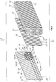
- Fig. 1 is a schematic and exploded view of a built-in element 10 in the form of a block of a plurality of obliquely corrugated grid mats 12, each grid mat as example in the FIGS. 2 or 3 shown in plan view, is configured.
- Each grid mat 12 has an oblique curvature of elevations 14 or peaks and valleys 16 or troughs along which first grid struts 18 extend.
- Adjacent elevations 14 and depressions 16 are connected to each other by flanks 19, wherein the installation element 10 is used, for example, according to the countercurrent principle by the fluid to be treated in the direction of arrow A (eg from bottom to top) through the mounting element 10 and the working fluid in Counter direction (see arrow B and consequently in this case from top to bottom) flows.
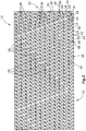
- the grid mat 12 also has two substantially parallel, corrugated longitudinal edges 20 and two transversely extending, also corrugated and parallel transverse edges 22 thereto.
- the first lattice struts 18 extend substantially between the two longitudinal edges 20 and partly, namely in the corner regions, between a longitudinal edge 20 and a transverse edge 22.
- the lattice mats 12 also have second lattice struts 24, which run essentially parallel to the longitudinal edges.
- the second lattice struts 24 are wave-shaped, since they extend at an acute angle to the extensions of the elevations 14 and the recesses 16.
- the second lattice struts 24 are connected at nodes 26 to the first lattice struts 18, wherein these nodes 26 are arranged along an imaginary node line 28.
- the grid mat 12 has third grid struts 30 and fourth grid struts 32, which intersect.
- the third grid struts 30 are parallel relative to each other;
- the fourth lattice struts 32 extend parallel to each other.
- Their crossing points 34, 36 are arranged alternately on the flanks 19 and in the recesses 16 and the elevations 14. The crossing points 36, along the projections 14 and the recesses 16 coincide with the nodes 26 between the first and second lattice struts 18, 24 together.
- the first grid struts 18 may be interrupted.
- the first lattice struts 18 have interruption sections 38, which are each arranged between two adjacent intersection points 36 on the respective lattice struts 18.
- the lattice struts 18 are in their areas between a longitudinal edge 20 and the next-adjacent node line 28 (second lattice strut 24) with advantage all not interrupted.
- the relative placement of the break sections 38 is ultimately arbitrary, care being taken that such break sections 38 for adjacent first grid stays 18 are not disposed between the same adjacent node lines 28.
- FIGS. 2 and 3 are still "eyes" or annular openings 40 to recognize, which are relative to the mounting element, aligned and through which a pull or push rod extends through, which additionally holds the mounting element together.
- contact plates 42 with openings 44 and corresponding contact pads 46 are formed with pins 48, which serve the pin hole connection of adjacent grid mats 12.
Landscapes
- Physics & Mathematics (AREA)
- Thermal Sciences (AREA)
- Chemical & Material Sciences (AREA)
- Engineering & Computer Science (AREA)
- Organic Chemistry (AREA)
- Chemical Kinetics & Catalysis (AREA)
- Mechanical Engineering (AREA)
- General Engineering & Computer Science (AREA)
- Physical Or Chemical Processes And Apparatus (AREA)
Description
Die Erfindung betrifft eine Vorrichtung zur Behandlung eines Fluids mit einem Arbeitsfluid, wobei die Vorrichtung vorzugsweise der Befeuchtung, Reinigung und oder Kühlung des zu behandelnden Fluids durch das Arbeitsfluid dient.The invention relates to a device for treating a fluid with a working fluid, wherein the device preferably serves to moisten, clean and / or cool the fluid to be treated by the working fluid.
Vorrichtungen zur Behandlung von Gasen, insbesondere zur Befeuchtung, Reinigung und/oder Kühlung von Gasen wie bspw. Luft sind grundsätzlich bekannt. Derartige Vorrichtungen können bspw. als Verdunstungsbefeuchter oder Stoffaustauscher dienen, die unter anderem zur Luftbefeuchtigung und gleichzeitigen Luftkühlung bspw. in Wohn- oder Bürogebäuden, Lagerhallen, Stallungen, Gewächshäusern und anderen Räumen oder auch von technischen Anlagen, bspw. für die Reinigung und insbesondere Entstaubung von Zu- oder Abluft für reaktive Gas- oder Luftreinigungen (insbesondere Entfernung von Geruchsstoffen wie bspw. Ammoniak aus der Stallabluft) eingesetzt werden. Die Abkühlung eines Gases mit Hilfe derartiger Vorrichtungen erfolgt nach dem Prinzip der adiabatischen Kühlung (Verdunstungskühlung). Behandlungsvorrichtungen dienen aber insbesondere auch als Wärmetauscher bspw. zum Einbau in bzw. an Kühltürmen und sind in der Ausgestaltung von Rieselkühlern grundsätzlich bekannt.Devices for the treatment of gases, in particular for moistening, cleaning and / or cooling of gases such as, for example, air are known in principle. Such devices can, for example, serve as evaporation humidifiers or material exchangers which, inter alia, for humidification and simultaneous air cooling. In residential or office buildings, warehouses, stables, greenhouses and other spaces or even of technical equipment, for example. For cleaning and dedusting of Supply or exhaust air for reactive gas or air purifications (in particular removal of odors such as, for example, ammonia from the stable exhaust air) are used. The cooling of a gas by means of such devices is carried out according to the principle of adiabatic cooling (evaporative cooling). But treatment devices are also used in particular as a heat exchanger, for example, for installation in or on cooling towers and are basically known in the design of trickle coolers.
Die bekannten Behandlungsvorrichtungen der vorstehend genannten Arten weisen Einbaueinrichtungen in Form von Einbaupaketen auf, die jeweils eine Vielzahl von Mattenelementen aufweisen, welche zumeist gewellt sind, so dass bei dichter Anlage benachbarter Mattenelemente sich kreuzende oder seitlich versetzte Kanäle entstehen, durch die über eine Eingangsseite der Vorrichtung das Gas einströmt, die Vorrichtung durchströmt und an einer gegenüberliegenden Ausgangsseite wieder herausströmt. Die Eingangs- und Ausgangsseiten der Vorrichtung werden durch gegenüberliegende Ränder einzelner nebeneinanderliegender Mattenelemente der eingangs- bzw. ausgangsseitig der Vorrichtung angeordneten Einbaupakete gebildet. Somit strömt also das zu behandelnde Fluid parallel zur Erstreckung der Mattenelemente zwischen deren betreffenden Ränder und zwischen den Mattenelementen hindurch. Grundsätzlich ist es aber auch möglich, dass das zu behandelnde Fluid quer zur Erstreckung der Mattenelemente strömt.The known treatment devices of the abovementioned types have installation devices in the form of installation packages, which each have a plurality of mat elements, which are usually corrugated, so that when close contact adjacent mat elements arise crossing or laterally offset channels through which an input side of the device the gas flows in, the device flows through and flows out again on an opposite outlet side. The input and output sides of the device are formed by opposing edges of individual juxtaposed mat elements of the input and output side of the device arranged mounting packages. Thus, that flows to it treating fluid parallel to the extension of the mat elements between their respective edges and between the mat elements therethrough. In principle, however, it is also possible that the fluid to be treated flows transversely to the extension of the mat elements.
Die Einbaupakete der vorstehend genannten Typen von Behandlungsvorrichtungen werden mit Flüssigkeit, dem sogenannten Arbeitsfluid, bei dem es sich insbesondere um Wasser handelt, benetzt, so dass das zu behandelnde Fluid an benetzten Flächen der Mattenelemente entlang strömt. Dabei ist es wünschenswert, dass die Benetzungsflüssigkeit eine möglichst große Oberfläche bildet und sich über einen längeren Zeitraum in der Vorrichtung bzw. den Einbaupaketen hält.The installation packages of the aforementioned types of treatment devices are wetted with liquid, the so-called working fluid, which is in particular water, so that the fluid to be treated flows along wetted surfaces of the mat elements. In this case, it is desirable for the wetting liquid to form as large a surface as possible and to remain in the device or the mounting packages over a relatively long period of time.
Im Regelfall sind die Mattenelemente rechteckförmig, wobei mehrere benachbarte Mattenelemente ein blockförmiges (quaderförmiges) Einbaupaket bilden. Es ist aber auch möglich, dass die Einbaupakete andere geometrische Formen aufweisen. So könnte man beispielsweise durch den Einsatz unterschiedlich großer, jeweils rechteckiger Mattenelemente ein Einbaupaket erhalten, das zylindrisch ist. Längs eines Durchmessers des Querschnitts des Zylinders sind dann die breitesten Mattenelemente angeordnet, wobei die jeweils benachbarten Mattenelemente in ihrer Breite abnehmen.As a rule, the mat elements are rectangular, wherein a plurality of adjacent mat elements form a block-shaped (cuboid) installation package. But it is also possible that the installation packages have other geometric shapes. For example, by using differently sized, respectively rectangular mat elements, one could obtain an installation package which is cylindrical. The widest mat elements are then arranged along a diameter of the cross section of the cylinder, with the respective adjacent mat elements decreasing in width.
Die bekannten Behandlungsvorrichtungen können nach dem Gegenstrom oder nach dem Kreuzstromprinzip arbeiten. Beim Gegenstromprinzip strömen das zu behandelnde Fluid und das zur Behandlung dieses Fluids eingesetzte Arbeitsfluid (bspw. Kühlmedium) entgegengesetzt zueinander. Bei Behandlungsvorrichtungen, die nach dem Kreuzstromprinzip arbeiten, kreuzen sich die Strömungsrichtungen des zu behandelnden Fluids und für des Arbeitsfluids, und zwar im Regelfall unter einem im Wesentlichen rechten Winkel.The known treatment devices can operate on the countercurrent or on the cross flow principle. In the counterflow principle, the fluid to be treated and the working fluid used for the treatment of this fluid (for example cooling medium) flow in opposite directions. In treatment devices operating on the cross-flow principle, the flow directions of the fluid to be treated and of the working fluid intersect, usually at a substantially right angle.
Für die Vorrichtungen der vorstehend genannten Arten hat sich seit vielen Jahren bereits ein Einbauelement bewährt, dass aus einzelnen schräg gewellten Gittermatten zusammengesetzt ist, wobei benachbarte Gittermatten gegeneinander verdreht sind, so dass sich die Schrägwellungen kreuzen. Beispiele für derartige Gittermatten sind in
Aufgabe der Erfindung ist es, die Effizienz der Einbauelemente für Vorrichtungen zur Behandlung eines Fluids weiter zu verbessern.The object of the invention is to further improve the efficiency of the installation elements for devices for the treatment of a fluid.
Zur Lösung dieser Aufgabe wird der Erfindung ein Einbauelement für eine Vorrichtung zur Behandlung eines Fluids, insbesondere eines Gases, insbesondere zur Befeuchtung, Reinigung und/oder Kühlung mittels eines Arbeitsfluids vorgeschlagen, wobei das Einbauelement versehen ist mit
- mindestens einer gewellten Gittermatte, die versehen ist mit
- geradlinig verlaufenden, wechselweise nebeneinander angeordneten Vertiefungen und Erhebungen mit diese verbindenden Flanken,
- zwei im Wesentlichen zueinander parallelen Längsrändern sowie zwei zu diesen querverlaufenden Querrändern,
- zueinander im Wesentlichen parallelen, geradlinigen ersten Gitterstreben, die jeweils in spitzen und stumpfen Winkeln, d.h. in Winkeln von ungleich 90°, zu sowohl den Längsrändern als auch den Querrändern verlaufen und sich längs der Vertiefungen unten und längs der Erhebungen oben erstrecken,
- wellenartigen zweiten Gitterstreben, die im Wesentlichen parallel zu den Längsrändern verlaufen und an längs von gedachten im Wesentlichen geraden Knotenpunktlinien angeordneten Knotenpunkten mit den ersten Gitterstreben verbunden sind und
- untereinander im Wesentlichen parallelen, wellenartigen dritten sowie ebenfalls untereinander im Wesentlichen parallelen, wellenartigen vierten Gitterstreben, die an den Knotenpunkten mit den ersten und mit den zweiten Gitterstreben verbunden sind, wobei die dritten und vierten Gitterstreben miteinander zusätzlich an Kreuzungspunkten (34) verbunden sind, welche an den zwischen den Vertiefungen und Erhebungen liegenden Flanken angeordnet sind.
- at least one corrugated grid mat, which is provided with
- rectilinear, alternately juxtaposed recesses and elevations with these connecting flanks,
- two substantially mutually parallel longitudinal edges and two transversely transverse edges to these,
- mutually substantially parallel, rectilinear first lattice struts each extending at acute and obtuse angles, ie at angles other than 90 °, to both the longitudinal edges and the transverse edges and extending along the depressions at the bottom and along the elevations above,
- wave-like second lattice struts, which are substantially parallel to the longitudinal edges and are connected to arranged along imaginary substantially straight node lines nodes with the first lattice struts, and
- mutually substantially parallel, wave-like third and likewise mutually substantially parallel, wave-like fourth lattice struts, which are connected at the nodes to the first and the second lattice struts, wherein the third and fourth lattice struts are additionally connected to each other at crossing points (34) are arranged at the lying between the recesses and elevations flanks.
Bei diesem Einbauelement ist erfindungsgemäß vorgesehen,
- dass jede erste Gitterstrebe längs ihrer Erstreckung zwischen den Längsrändern oder zwischen einem Längsrand und einem Querrand mindestens einen Unterbrechungsabschnitt aufweist und
- dass die Unterbrechungsabschnitte benachbarter erster Gitterstreben seitlich versetzt und insbesondere überlappungsfrei angeordnet sind.
- that each first grid strut has along its extension between the longitudinal edges or between a longitudinal edge and a transverse edge at least one interruption section, and
- that the interruption portions of adjacent first grid struts are laterally offset and in particular arranged without overlapping.
Erfindungsgemäß sind also die ersten Gitterstreben, die längs der Vertiefungen und längs der Erhebungen verlaufen, unterbrochen und zwar zumindest einmal pro erster Gitterstrebe. An diesen Gitterstreben läuft in eingebautem Zustand des Einbauelements das Arbeitsfluid entlang, das eine möglichst große Oberfläche bilden und eine möglichst große Verweildauer haben sollte. Die Vergrößerung der Oberfläche kann bspw. dadurch erzielt werden, dass längs der ersten Gitterstreben verlaufende Arbeitsfluidtropfen abreißen, womit sie auf in vertikaler Richtung folgende Gitterstreben auftreffen, dort "zerspringen" und damit eine Oberflächenvergrößerung herbeiführen. Dies wird erfindungsgemäß unterstützt durch die unterbrochenen ersten Gitterstreben.According to the invention, therefore, the first lattice struts, which extend along the recesses and along the elevations, interrupted and that at least once per first lattice strut. In the built-in state of the installation element, the working fluid runs along these lattice struts, which form the largest possible surface area and should have the greatest possible residence time. The enlargement of the surface can be achieved, for example, by tearing down working fluid drops running along the first lattice struts, thus impinging on the lattice struts following in the vertical direction, "shattering" there and thus causing an increase in surface area. This is supported according to the invention by the interrupted first grid struts.
Bei einer vorteilhaften Ausgestaltung der Erfindung ist bspw. vorgesehen, dass sich ein Unterbrechungsabschnitt einer ersten Gitterstrebe zwischen zwei längs der Gitterstrebe benachbarten Knotenpunkten erstreckt. Die Länge eines Unterbrechungsabschnitts ist grundsätzlich beliebig wählbar, es hat sich aber als vorteilhaft erwiesen, denjenigen Abschnitt einer ersten Gitterstrebe zu unterbrechen, der sich zwischen zwei benachbarten Knotenpunkten verbindet. Dieser Unterbrechungsabschnitt kann sich von Knotenpunkt zu Knotenpunkt oder aber auch über eine kürzere Strecke zwischen den beiden Knotenpunkten erstrecken.In an advantageous embodiment of the invention, for example, it is provided that an interruption section of a first lattice strut extends between two nodes adjacent to the lattice strut. The length of an interruption section can basically be selected arbitrarily, but it has proved to be advantageous to interrupt that section of a first grid strut which connects between two adjacent nodes. This interruption section can extend from node to node or even over a shorter distance between the two nodes.
Ferner ist es zweckmäßig, wenn die Unterbrechungsabschnitte benachbarter erster Gitterstreben um den Abstand zwischen mindestens zwei längs einer ersten Gitterstrebe aufeinanderfolgenden benachbarten Knotenpunkten seitlich versetzt sind. Aus Stabilitätsgründen ist es von Vorteil, wenn die Unterbrechungsabschnitte der Gitterstreben nicht längs eines zu einem Randabschnitt der Gittermatte parallel verlaufenden Bereichs angeordnet sind, sondern seitlich versetzt sind. Insoweit dient diese Ausgestaltung der Erfindung einer erhöhten Festigkeit und Stabilität des aus den Gittermatten zusammengesetzten Einbauelements.Furthermore, it is expedient if the interruption sections of adjacent first grid struts are laterally offset by the distance between at least two adjacent node points succeeding each other along a first grid strut. For reasons of stability, it is advantageous if the interruption sections of the lattice struts do not extend along one to one edge section the grid mat are arranged parallel extending portion, but are offset laterally. In that regard, this embodiment of the invention provides increased strength and stability of the assembled from the grid mats mounting element.
Die bereits oben angesprochenen Knotenpunkte, d.h. die Verbindungspunkte zwischen den zweiten und den ersten Gitterstreben, sind insbesondere entlang von Knotenpunktlinien angeordnet, die ihrerseits wiederum parallel zu den Längsrändern (oder alternativ zu den Querrändern) verlaufen.The nodes already discussed above, i. the connection points between the second and the first lattice struts are in particular arranged along node lines which in turn extend parallel to the longitudinal edges (or alternatively to the transverse edges).
Aus Stabilitätsgründen kann es ferner von Vorteil sein, wenn die Unterbrechungsabschnitte nicht direkt benachbart zu den Längs- bzw. Querrändern angeordnet sind. Insoweit von Vorteil ist es also, wenn die Unterbrechungsabschnitte der ersten Gitterstreben außerhalb von solchen Längserstreckungsbereichen dieser ersten Gitterstreben angeordnet sind, die sich zwischen einem Längsrand oder einem Querrand und dem dazu längs der ersten Gitterstrebe jeweils nächstbenachbarten Knotenpunkt befinden.For stability reasons, it may also be advantageous if the interruption sections are not arranged directly adjacent to the longitudinal or transverse edges. In that regard, it is advantageous if the interruption sections of the first lattice struts are arranged outside of such longitudinal extension regions of these first lattice struts, which are located between a longitudinal edge or a transverse edge and the next thereto next to the first lattice strut next adjacent node.
In weiterer Ausgestaltung der Erfindung kann es zweckmäßig sein, dass entlang der Längsränder sowie an denjenigen Knotenpunkten, die längs mindestens zweier zwischen den Längsrändern angeordneten und parallel zu diesen verlaufenden Knotenpunktlinien angeordnet sind, korrespondierende Zapfen- und Loch-Verbindungselemente zur mechanischen Verbindung benachbarter Gittermatten ausgebildet sind. Anstelle von Zapfen-Loch-Verbindungselementen zur mechanischen Verbindung benachbarter Gittermatten können diese auch miteinander verschweißt oder auf andere Art und Weise mechanisch verbunden sein. Schließlich ist auch möglich, die Aufeinanderfolge benachbarter Gittermatten des Einbauelements durch Zug- bzw. Druckstäbe, die sich quer durch die Gittermatten erstrecken, mit größerer Zuverlässigkeit zusammenzuhalten.In a further embodiment of the invention, it may be expedient that along the longitudinal edges and at those nodes which are arranged along at least two arranged between the longitudinal edges and parallel to these node lines, corresponding pin and hole connecting elements for mechanical connection of adjacent grid mats are formed , Instead of pin-hole connecting elements for the mechanical connection of adjacent grid mats they can also be welded together or mechanically connected in other ways. Finally, it is also possible to hold together the succession of adjacent grid mats of the mounting element by means of tension or compression bars which extend transversely through the grid mats, with greater reliability.
Durch den seitlichen Versatz der Unterbrechungsabschnitte benachbarter erster Gitterstreben ergibt sich mit Vorteil, dass die Unterbrechungsabschnitte der benachbarter Gittermatten des Einbauelements durch Zug- bzw. Druckstäbe, die sich quer durch die Gittermatten erstrecken, mit größerer Zuverlässigkeit zusammenzuhalten.Due to the lateral offset of the interruption portions of adjacent first grid struts results with advantage that the interruption sections of adjacent grid mats of the mounting element by tensile or compression bars which extend across the grid mats to hold together with greater reliability.
Durch den seitlichen Versatz der Unterbrechungsabschnitte benachbarter erster Gitterstreben ergibt sich mit Vorteil, dass die Unterbrechungsabschnitte der ersten Gitterstreben entlang von Streifenbereichen angeordnet sind, die in einem spitzen Winkel zu den Längs- und Querrändern verlaufen.The lateral offset of the interruption sections of adjacent first grid struts results in the advantage that the interruption sections of the first grid struts are arranged along strip regions which run at an acute angle to the longitudinal and transverse edges.
Wie bereits oben erwähnt, weist jede erste Gitterstrebe grundsätzlich einen einzigen Unterbrechungsabschnitt auf. Es hat sich als zweckmäßig herausgestellt, wenn jede erste Gitterstrebe mehrere Unterbrechungsabschnitte bspw. zwei oder drei Unterbrechungsabschnitte, aufweist. Hier muss ein vernünftiger Kompromiss zwischen dem Vorteil des Abreißens eines Arbeitsfluidtropfens für die Oberflächenvergrößerung des Arbeitsfluids einerseits und der Stabilität des Einbauelements andererseits gefunden werden.As already mentioned above, each first lattice strut basically has a single interruption section. It has proven to be expedient if each first grid strut has a plurality of interruption sections, for example two or three interruption sections. Here, a reasonable compromise must be found between the advantage of rupturing a working fluid drop for the surface enlargement of the working fluid, on the one hand, and the stability of the paving member, on the other hand.
Schließlich ist es auch möglich, pro Gittermatte erste Gitterstreben vorzusehen, die unterschiedlich viele Unterbrechungsabschnitte aufweisen. So kann beispielsweise mit Vorteil vorgesehen sein, dass jede erste Gitterstrebe einen, zwei oder drei Unterbrechungsabschnitte aufweist, wobei benachbarte erste Gitterstreben eine gleiche oder eine ungleiche Anzahl von Unterbrechungsabschnitten aufweisen, und/oder das erste Gitterstreben mit einem Unterbrechungsabschnitt sowie erste Gitterstreben mit zwei Unterbrechungsabschnitten, und/oder erste Gitterstreben mit einem Unterbrechungsabschnitt sowie erste Gitterstreben mit drei Unterbrechungsabschnitten, und/oder erste Gitterstreben mit zwei Unterbrechungsabschnitten sowie erste Gitterstreben mit drei Unterbrechungsabschnitten, und/oder erste Gitterstreben mit einem Unterbrechungsabschnitt, erste Gitterstreben mit zwei Unterbrechungsabschnitten sowie erste Gitterstreben mit drei Unterbrechungsabschnitten existieren.Finally, it is also possible to provide first grid struts per grid mat, which have different numbers of interruption sections. For example, it can advantageously be provided that each first grid strut has one, two or three interrupt sections, adjacent first grid struts having the same or an uneven number of interrupt sections, and / or the first grid strut having a break section and first grid struts having two interrupt sections; and / or first grid struts having a break portion and first grid struts having three break portions, and / or first grid struts having two break portions and first grid struts having three break portions, and / or first grid struts having a break portion, first grid struts having two break portions, and first grid struts having three break portions exist.
Die Erfindung wird nachfolgend mehrerer Ausführungsbeispiele sowie unter Bezugnahme auf die Zeichnung näher beschrieben. Im Einzelnen zeigen dabei:
- Fig. 1
- eine schematische Darstellung eines Einbauelements, das aus einer Vielzahl von schräg gewellten Gittermatten mit sich wechselweise kreuzenden Wellungen zusammengesetzt ist, wobei das Einbauelement in seiner Einbausituation dargestellt ist, in der die Gittermatten hochkant angeordnet sind.
- Fig. 2
- eine Draufsicht auf Ausschnitte einer Gittermatte mit unterbrochenen Gitterstreben gemäß einem ersten Ausführungsbeispiel und
- Fig. 3
- eine Draufsicht auf Ausschnitte einer Gittermatte mit unterbrochenen Gitterstreben gemäß einem zweiten Ausführungsbeispiel.
- Fig. 1
- a schematic representation of a built-in element, which is composed of a plurality of obliquely corrugated mesh mats with alternately crossing corrugations, wherein the mounting element is shown in its installation situation, in which the grid mats are arranged edgewise.
- Fig. 2
- a plan view of sections of a grid mat with broken grid struts according to a first embodiment and
- Fig. 3
- a plan view of sections of a grid mat with broken lattice struts according to a second embodiment.
In
Neben den ersten Gitterstreben 18 weisen die Gittermatten 12 auch zweite Gitterstreben 24 auf, die im Wesentlichen parallel zu den Längsrändern verlaufen. Die zweiten Gitterstreben 24 sind wellenförmig, da sie in einem spitzen Winkel zu den Erstreckungen der Erhebungen 14 und der Vertiefungen 16 verlaufen. Die zweiten Gitterstreben 24 sind an Knotenpunkten 26 mit den ersten Gitterstreben 18 verbunden, wobei diese Knotenpunkte 26 längs einer gedachten Knotenpunktlinie 28 angeordnet sind.In addition to the first lattice struts 18, the
Schließlich weist die Gittermatte 12 dritte Gitterstreben 30 sowie vierte Gitterstreben 32 auf, die sich kreuzen. Die dritten Gitterstreben 30 sind dabei relativ zueinander parallel; ebenso verlaufen die vierten Gitterstreben 32 untereinander parallel. Ihre Kreuzungspunkte 34, 36 sind wechselweise an den Flanken 19 sowie in den Vertiefungen 16 und den Erhebungen 14 angeordnet. Die Kreuzungspunkte 36, längs der Erhebungen 14 und der Vertiefungen 16 fallen mit den Knotenpunkten 26 zwischen den ersten und zweiten Gitterstreben 18, 24 zusammen.Finally, the
In den
Dabei sind die Gitterstreben 18 in ihren Bereichen zwischen einem Längsrand 20 und der dazu nächstbenachbarten Knotenpunktlinie 28 (zweite Gitterstrebe 24) mit Vorteil sämtlich nicht unterbrochen. Die relative Anordnung der Unterbrechungsabschnitte 38 ist letztendlich beliebig, wobei darauf geachtet werden sollte, dass derartige Unterbrechungsabschnitte 38 für benachbarte erste Gitterstreben 18 nicht zwischen denselben benachbarten Knotenpunktlinien 28 angeordnet werden.In this case, the lattice struts 18 are in their areas between a
In den
Claims (10)
- Installation element for a device for the treatment of a fluid, in particular a gas, in particular for the humidification, purification and/or cooling by means of a working fluid, comprising- at least a corrugated grid mat (12) provided withcharacterized in- linearly extending valleys (16) and ridges (14) alternately arranged one beside the other, having flanks (19) connecting the same,- two longitudinal edges (20) substantially parallel to each other, as well as transversal edges (22) extending transversely thereto,- linear first grid bars (18), substantially parallel to each other, which extend at angles different from 90° with respect to both the longitudinal edges (20) and the transversal edges (22), and which extend at the bottom along the depressions (16) and at the top along the protrusions (14),- wave-like second grid bars (24) extending substantially parallel to the longitudinal edges (20) and connected with the first grid bars (18) at junctions (26) arranged along imaginary, substantially linear junction lines (28), und- wave-like third grid bars (30), substantially parallel with respect to each other, and wave-like fourth grid-bars (32), also substantially parallel with respect to each other, said grid bars being connected with the first and second grid bars (18, 24) at the junctions (26), the third and fourth grid bars (30, 32) being additionally connected with each other at junctions (34) arranged at the flanks (19) lying between the depressions (16) and the protrusions (14),- that each first grid bar (18) has at least one interruption zone (38) along its extension between the longitudinal edges (20) or between a longitudinal edge (20) and a transversal edge (22), and- that the interruption zones (38) of adjacent first grid bars (18) are arranged laterally offset and in particular without overlap.
- Installation element of claim 1, characterized in that an interruption zone (38) of a first grid bar (18) extends between two junctions (26) adjacent along said grid bar.
- Installation element of claim 1 or 2, characterized in that the interruption zones (38) of adjacent first grid bars (18) are laterally offset by the distance between at least two successive junctions (26) adjacent along a first grid bar (18).
- Installation element of one of claims 1 to 3, characterized in that the junctions (26) are arranged along junction lines (28) that extend parallel to the longitudinal edges (20).
- Installation element of one of claims 1 to 4, characterized in that corresponding pin and hole connecting elements for the mechanical connection of adjacent grid mats (12) are formed along the longitudinal edges (20), as well as at those junctions (26) that are arranged along at least two junction lines (28) situated between the longitudinal edges (20) and extending parallel to the same.
- Installation element of one of claims 1 to 5, characterized in that the interruption zones (38) of the first grid bars (18) are arranged along strip portions that extend under an acute angle to the longitudinal and transversal edges (20, 22).
- Installation element of one of claims 1 to 6, characterized in that each first grid bar (18) has a single interruption zone (38).
- Installation element of one of claims 1 to 6, characterized in that each first grid bar (18) has two or three interruption zone (38).
- Installation element of one of claims 1 to 6, characterized in that each first grid bar (18) has one, two or three interruption zone (38), wherein adjacent first grid bars (18) have an equal or a different number of interruption zones (38), and/or that first grid bars (18) with one interruption zone (38), as well as first grid bars (18) with two interruption zones (38) exist, and/or that first grid bars (18) with one interruption zone (38), as well as first grid bars (18) with three interruption zones (38) exist, and/or that first grid bars (18) with two interruption zones (38), as well as first grid bars (18) with three interruption zones (38) exist, and/or first grid bars (18) with one interruption zone (38), first grid bars (18) with two interruption zones (38), as well as first grid bars (18) with three interruption zones (38) exist.
- Installation element of one of claims 1 to 9, characterized in that the interruption zones (38) of the first grid bars (18) are arranged outside of such portions of the longitudinal extension of these first grid bars (18) that are situated between a longitudinal edge (20) of a transversal edge (22) and the respective junction (26) nearest to the same along the first grid bar (18).
Applications Claiming Priority (1)
| Application Number | Priority Date | Filing Date | Title |
|---|---|---|---|
| DE102013225145.9A DE102013225145B4 (en) | 2013-12-06 | 2013-12-06 | Built-in element for a device for the treatment of a fluid |
Publications (2)
| Publication Number | Publication Date |
|---|---|
| EP2881170A1 EP2881170A1 (en) | 2015-06-10 |
| EP2881170B1 true EP2881170B1 (en) | 2017-11-29 |
Family
ID=52021027
Family Applications (1)
| Application Number | Title | Priority Date | Filing Date |
|---|---|---|---|
| EP14196792.7A Active EP2881170B1 (en) | 2013-12-06 | 2014-12-08 | Installation element for a device for treating a fluid |
Country Status (2)
| Country | Link |
|---|---|
| EP (1) | EP2881170B1 (en) |
| DE (1) | DE102013225145B4 (en) |
Families Citing this family (1)
| Publication number | Priority date | Publication date | Assignee | Title |
|---|---|---|---|---|
| EP4495532B1 (en) | 2023-07-19 | 2026-02-11 | Hewitech GmbH & Co. KG | Corrugated mesh mat |
Family Cites Families (5)
| Publication number | Priority date | Publication date | Assignee | Title |
|---|---|---|---|---|
| DE19733480C2 (en) * | 1997-08-01 | 1999-06-24 | Gea Kuehlturmbau Gmbh | Installation pack for material and / or heat exchange between gases and liquids |
| DE102005051882B4 (en) * | 2005-10-29 | 2007-08-02 | Hewitech Gmbh & Co. Kg | Installation element for a heat exchanger or for installation in the ground for drainage purposes |
| DE102006005112A1 (en) * | 2006-02-04 | 2007-08-09 | Hewitech Gmbh & Co. Kg | Plastic foil for installation element for use in installation in ripple condenser, particularly cooling tower for cooling purposes or to install in ground for drinage purpose, has two surface area where one of two surface area has openings |
| DE202009004513U1 (en) * | 2009-03-31 | 2009-07-16 | Dewath, Michael | Grid plates with spacers |
| DE102009052045A1 (en) * | 2009-11-05 | 2011-05-12 | Rvt Process Equipment Gmbh | Corrugated packing grid and ordered, composed of several packing lattice pack |
-
2013
- 2013-12-06 DE DE102013225145.9A patent/DE102013225145B4/en not_active Expired - Fee Related
-
2014
- 2014-12-08 EP EP14196792.7A patent/EP2881170B1/en active Active
Non-Patent Citations (1)
| Title |
|---|
| None * |
Also Published As
| Publication number | Publication date |
|---|---|
| DE102013225145B4 (en) | 2015-07-09 |
| DE102013225145A1 (en) | 2015-06-11 |
| EP2881170A1 (en) | 2015-06-10 |
Similar Documents
| Publication | Publication Date | Title |
|---|---|---|
| DE19733480C2 (en) | Installation pack for material and / or heat exchange between gases and liquids | |
| EP2496342B1 (en) | Corrugated packing grid and structured packing assembled from several packing grids | |
| EP2310756B1 (en) | Insert element for inserting in a device for moistening, cleaning and/or cooling a fluid, in particular a gas, such as, for example, air, and a method for producing an insert body with such a insert element | |
| EP3690378B1 (en) | Installation element for a device for treating a usage fluid with a working fluid | |
| EP3433544B1 (en) | Insert element for inserting into a device for humidifying, cleaning and/or cooling a fluid, in particular a gas, such as, for example, air | |
| EP2881170B1 (en) | Installation element for a device for treating a fluid | |
| EP3583360B1 (en) | Trickle structures | |
| EP3049748A1 (en) | Assembly device for a device for treating a useful fluid, and method for producing such an assembly device | |
| EP3535539B1 (en) | Installation unit for a device for treating a useful fluid with a working fluid | |
| DE69416544T2 (en) | Package and method for producing a package | |
| DE102005051882B4 (en) | Installation element for a heat exchanger or for installation in the ground for drainage purposes | |
| DE29613862U1 (en) | Installation element for heat exchangers | |
| DE202013009854U1 (en) | Built-in element for a device for the treatment of a fluid | |
| EP2881694B1 (en) | Mounting device for a device for handling a flowing fluid | |
| DE2312649B2 (en) | HEAT AND / OR MASS EXCHANGER WITH DIRECT CONTACT OF A LIQUID AND A GAS | |
| EP4495532B1 (en) | Corrugated mesh mat | |
| EP2853852B1 (en) | Installation element for a device for treating a usage fluid by means of a working fluid | |
| DE1948282B2 (en) | Honeycomb body for treating liquids using gases | |
| DE202013009855U1 (en) | Installation device for a device for the treatment of a flowing fluid | |
| WO2010112005A2 (en) | Grid plates comprising spacers | |
| WO2017174494A1 (en) | Installation device for an apparatus for treating a gas with a working fluid | |
| DE102013219779B4 (en) | Support device for drip filter installations | |
| DE202016002100U1 (en) | Installation device for a device for treating a gas with a working fluid | |
| DE102017103178A1 (en) | Device for moistening, cleaning and / or cooling a gas, in particular of air | |
| DE102004025333A1 (en) | Stacks connecting device, has corrugated plastic foils with interconnecting parts having projecting units, which are provided with openings that align with one another for accommodating locking rod, which passes through foils |
Legal Events
| Date | Code | Title | Description |
|---|---|---|---|
| PUAI | Public reference made under article 153(3) epc to a published international application that has entered the european phase |
Free format text: ORIGINAL CODE: 0009012 |
|
| 17P | Request for examination filed |
Effective date: 20141208 |
|
| AK | Designated contracting states |
Kind code of ref document: A1 Designated state(s): AL AT BE BG CH CY CZ DE DK EE ES FI FR GB GR HR HU IE IS IT LI LT LU LV MC MK MT NL NO PL PT RO RS SE SI SK SM TR |
|
| AX | Request for extension of the european patent |
Extension state: BA ME |
|
| R17P | Request for examination filed (corrected) |
Effective date: 20151208 |
|
| RBV | Designated contracting states (corrected) |
Designated state(s): AL AT BE BG CH CY CZ DE DK EE ES FI FR GB GR HR HU IE IS IT LI LT LU LV MC MK MT NL NO PL PT RO RS SE SI SK SM TR |
|
| 17Q | First examination report despatched |
Effective date: 20160517 |
|
| GRAP | Despatch of communication of intention to grant a patent |
Free format text: ORIGINAL CODE: EPIDOSNIGR1 |
|
| STAA | Information on the status of an ep patent application or granted ep patent |
Free format text: STATUS: GRANT OF PATENT IS INTENDED |
|
| INTG | Intention to grant announced |
Effective date: 20170512 |
|
| GRAJ | Information related to disapproval of communication of intention to grant by the applicant or resumption of examination proceedings by the epo deleted |
Free format text: ORIGINAL CODE: EPIDOSDIGR1 |
|
| GRAL | Information related to payment of fee for publishing/printing deleted |
Free format text: ORIGINAL CODE: EPIDOSDIGR3 |
|
| GRAS | Grant fee paid |
Free format text: ORIGINAL CODE: EPIDOSNIGR3 |
|
| STAA | Information on the status of an ep patent application or granted ep patent |
Free format text: STATUS: EXAMINATION IS IN PROGRESS |
|
| GRAP | Despatch of communication of intention to grant a patent |
Free format text: ORIGINAL CODE: EPIDOSNIGR1 |
|
| STAA | Information on the status of an ep patent application or granted ep patent |
Free format text: STATUS: GRANT OF PATENT IS INTENDED |
|
| GRAA | (expected) grant |
Free format text: ORIGINAL CODE: 0009210 |
|
| STAA | Information on the status of an ep patent application or granted ep patent |
Free format text: STATUS: THE PATENT HAS BEEN GRANTED |
|
| INTC | Intention to grant announced (deleted) | ||
| INTG | Intention to grant announced |
Effective date: 20171016 |
|
| AK | Designated contracting states |
Kind code of ref document: B1 Designated state(s): AL AT BE BG CH CY CZ DE DK EE ES FI FR GB GR HR HU IE IS IT LI LT LU LV MC MK MT NL NO PL PT RO RS SE SI SK SM TR |
|
| REG | Reference to a national code |
Ref country code: CH Ref legal event code: EP |
|
| REG | Reference to a national code |
Ref country code: AT Ref legal event code: REF Ref document number: 949887 Country of ref document: AT Kind code of ref document: T Effective date: 20171215 |
|
| REG | Reference to a national code |
Ref country code: IE Ref legal event code: FG4D Free format text: LANGUAGE OF EP DOCUMENT: GERMAN |
|
| REG | Reference to a national code |
Ref country code: DE Ref legal event code: R096 Ref document number: 502014006393 Country of ref document: DE |
|
| REG | Reference to a national code |
Ref country code: NL Ref legal event code: MP Effective date: 20171129 |
|
| REG | Reference to a national code |
Ref country code: LT Ref legal event code: MG4D |
|
| PG25 | Lapsed in a contracting state [announced via postgrant information from national office to epo] |
Ref country code: FI Free format text: LAPSE BECAUSE OF FAILURE TO SUBMIT A TRANSLATION OF THE DESCRIPTION OR TO PAY THE FEE WITHIN THE PRESCRIBED TIME-LIMIT Effective date: 20171129 Ref country code: SE Free format text: LAPSE BECAUSE OF FAILURE TO SUBMIT A TRANSLATION OF THE DESCRIPTION OR TO PAY THE FEE WITHIN THE PRESCRIBED TIME-LIMIT Effective date: 20171129 Ref country code: ES Free format text: LAPSE BECAUSE OF FAILURE TO SUBMIT A TRANSLATION OF THE DESCRIPTION OR TO PAY THE FEE WITHIN THE PRESCRIBED TIME-LIMIT Effective date: 20171129 Ref country code: LT Free format text: LAPSE BECAUSE OF FAILURE TO SUBMIT A TRANSLATION OF THE DESCRIPTION OR TO PAY THE FEE WITHIN THE PRESCRIBED TIME-LIMIT Effective date: 20171129 Ref country code: NO Free format text: LAPSE BECAUSE OF FAILURE TO SUBMIT A TRANSLATION OF THE DESCRIPTION OR TO PAY THE FEE WITHIN THE PRESCRIBED TIME-LIMIT Effective date: 20180228 |
|
| PG25 | Lapsed in a contracting state [announced via postgrant information from national office to epo] |
Ref country code: BG Free format text: LAPSE BECAUSE OF FAILURE TO SUBMIT A TRANSLATION OF THE DESCRIPTION OR TO PAY THE FEE WITHIN THE PRESCRIBED TIME-LIMIT Effective date: 20180228 Ref country code: RS Free format text: LAPSE BECAUSE OF FAILURE TO SUBMIT A TRANSLATION OF THE DESCRIPTION OR TO PAY THE FEE WITHIN THE PRESCRIBED TIME-LIMIT Effective date: 20171129 Ref country code: HR Free format text: LAPSE BECAUSE OF FAILURE TO SUBMIT A TRANSLATION OF THE DESCRIPTION OR TO PAY THE FEE WITHIN THE PRESCRIBED TIME-LIMIT Effective date: 20171129 Ref country code: LV Free format text: LAPSE BECAUSE OF FAILURE TO SUBMIT A TRANSLATION OF THE DESCRIPTION OR TO PAY THE FEE WITHIN THE PRESCRIBED TIME-LIMIT Effective date: 20171129 Ref country code: GR Free format text: LAPSE BECAUSE OF FAILURE TO SUBMIT A TRANSLATION OF THE DESCRIPTION OR TO PAY THE FEE WITHIN THE PRESCRIBED TIME-LIMIT Effective date: 20180301 |
|
| PG25 | Lapsed in a contracting state [announced via postgrant information from national office to epo] |
Ref country code: NL Free format text: LAPSE BECAUSE OF FAILURE TO SUBMIT A TRANSLATION OF THE DESCRIPTION OR TO PAY THE FEE WITHIN THE PRESCRIBED TIME-LIMIT Effective date: 20171129 |
|
| PG25 | Lapsed in a contracting state [announced via postgrant information from national office to epo] |
Ref country code: SK Free format text: LAPSE BECAUSE OF FAILURE TO SUBMIT A TRANSLATION OF THE DESCRIPTION OR TO PAY THE FEE WITHIN THE PRESCRIBED TIME-LIMIT Effective date: 20171129 Ref country code: CZ Free format text: LAPSE BECAUSE OF FAILURE TO SUBMIT A TRANSLATION OF THE DESCRIPTION OR TO PAY THE FEE WITHIN THE PRESCRIBED TIME-LIMIT Effective date: 20171129 Ref country code: CY Free format text: LAPSE BECAUSE OF FAILURE TO SUBMIT A TRANSLATION OF THE DESCRIPTION OR TO PAY THE FEE WITHIN THE PRESCRIBED TIME-LIMIT Effective date: 20171129 Ref country code: EE Free format text: LAPSE BECAUSE OF FAILURE TO SUBMIT A TRANSLATION OF THE DESCRIPTION OR TO PAY THE FEE WITHIN THE PRESCRIBED TIME-LIMIT Effective date: 20171129 Ref country code: DK Free format text: LAPSE BECAUSE OF FAILURE TO SUBMIT A TRANSLATION OF THE DESCRIPTION OR TO PAY THE FEE WITHIN THE PRESCRIBED TIME-LIMIT Effective date: 20171129 |
|
| REG | Reference to a national code |
Ref country code: CH Ref legal event code: PL |
|
| REG | Reference to a national code |
Ref country code: DE Ref legal event code: R097 Ref document number: 502014006393 Country of ref document: DE |
|
| PG25 | Lapsed in a contracting state [announced via postgrant information from national office to epo] |
Ref country code: RO Free format text: LAPSE BECAUSE OF FAILURE TO SUBMIT A TRANSLATION OF THE DESCRIPTION OR TO PAY THE FEE WITHIN THE PRESCRIBED TIME-LIMIT Effective date: 20171129 Ref country code: SM Free format text: LAPSE BECAUSE OF FAILURE TO SUBMIT A TRANSLATION OF THE DESCRIPTION OR TO PAY THE FEE WITHIN THE PRESCRIBED TIME-LIMIT Effective date: 20171129 Ref country code: PL Free format text: LAPSE BECAUSE OF FAILURE TO SUBMIT A TRANSLATION OF THE DESCRIPTION OR TO PAY THE FEE WITHIN THE PRESCRIBED TIME-LIMIT Effective date: 20171129 Ref country code: IT Free format text: LAPSE BECAUSE OF FAILURE TO SUBMIT A TRANSLATION OF THE DESCRIPTION OR TO PAY THE FEE WITHIN THE PRESCRIBED TIME-LIMIT Effective date: 20171129 |
|
| REG | Reference to a national code |
Ref country code: IE Ref legal event code: MM4A |
|
| PG25 | Lapsed in a contracting state [announced via postgrant information from national office to epo] |
Ref country code: LU Free format text: LAPSE BECAUSE OF NON-PAYMENT OF DUE FEES Effective date: 20171208 Ref country code: MT Free format text: LAPSE BECAUSE OF FAILURE TO SUBMIT A TRANSLATION OF THE DESCRIPTION OR TO PAY THE FEE WITHIN THE PRESCRIBED TIME-LIMIT Effective date: 20171129 |
|
| PLBE | No opposition filed within time limit |
Free format text: ORIGINAL CODE: 0009261 |
|
| STAA | Information on the status of an ep patent application or granted ep patent |
Free format text: STATUS: NO OPPOSITION FILED WITHIN TIME LIMIT |
|
| REG | Reference to a national code |
Ref country code: BE Ref legal event code: MM Effective date: 20171231 |
|
| PG25 | Lapsed in a contracting state [announced via postgrant information from national office to epo] |
Ref country code: IE Free format text: LAPSE BECAUSE OF NON-PAYMENT OF DUE FEES Effective date: 20171208 |
|
| 26N | No opposition filed |
Effective date: 20180830 |
|
| PG25 | Lapsed in a contracting state [announced via postgrant information from national office to epo] |
Ref country code: SI Free format text: LAPSE BECAUSE OF FAILURE TO SUBMIT A TRANSLATION OF THE DESCRIPTION OR TO PAY THE FEE WITHIN THE PRESCRIBED TIME-LIMIT Effective date: 20171129 Ref country code: LI Free format text: LAPSE BECAUSE OF NON-PAYMENT OF DUE FEES Effective date: 20171231 Ref country code: CH Free format text: LAPSE BECAUSE OF NON-PAYMENT OF DUE FEES Effective date: 20171231 Ref country code: BE Free format text: LAPSE BECAUSE OF NON-PAYMENT OF DUE FEES Effective date: 20171231 |
|
| REG | Reference to a national code |
Ref country code: FR Ref legal event code: ST Effective date: 20181102 |
|
| PG25 | Lapsed in a contracting state [announced via postgrant information from national office to epo] |
Ref country code: FR Free format text: LAPSE BECAUSE OF NON-PAYMENT OF DUE FEES Effective date: 20180129 |
|
| PG25 | Lapsed in a contracting state [announced via postgrant information from national office to epo] |
Ref country code: HU Free format text: LAPSE BECAUSE OF FAILURE TO SUBMIT A TRANSLATION OF THE DESCRIPTION OR TO PAY THE FEE WITHIN THE PRESCRIBED TIME-LIMIT; INVALID AB INITIO Effective date: 20141208 Ref country code: MC Free format text: LAPSE BECAUSE OF FAILURE TO SUBMIT A TRANSLATION OF THE DESCRIPTION OR TO PAY THE FEE WITHIN THE PRESCRIBED TIME-LIMIT Effective date: 20171129 |
|
| GBPC | Gb: european patent ceased through non-payment of renewal fee |
Effective date: 20181208 |
|
| PG25 | Lapsed in a contracting state [announced via postgrant information from national office to epo] |
Ref country code: MK Free format text: LAPSE BECAUSE OF FAILURE TO SUBMIT A TRANSLATION OF THE DESCRIPTION OR TO PAY THE FEE WITHIN THE PRESCRIBED TIME-LIMIT Effective date: 20171129 |
|
| PG25 | Lapsed in a contracting state [announced via postgrant information from national office to epo] |
Ref country code: GB Free format text: LAPSE BECAUSE OF NON-PAYMENT OF DUE FEES Effective date: 20181208 |
|
| PG25 | Lapsed in a contracting state [announced via postgrant information from national office to epo] |
Ref country code: TR Free format text: LAPSE BECAUSE OF FAILURE TO SUBMIT A TRANSLATION OF THE DESCRIPTION OR TO PAY THE FEE WITHIN THE PRESCRIBED TIME-LIMIT Effective date: 20171129 |
|
| PG25 | Lapsed in a contracting state [announced via postgrant information from national office to epo] |
Ref country code: PT Free format text: LAPSE BECAUSE OF FAILURE TO SUBMIT A TRANSLATION OF THE DESCRIPTION OR TO PAY THE FEE WITHIN THE PRESCRIBED TIME-LIMIT Effective date: 20171129 |
|
| PG25 | Lapsed in a contracting state [announced via postgrant information from national office to epo] |
Ref country code: AL Free format text: LAPSE BECAUSE OF FAILURE TO SUBMIT A TRANSLATION OF THE DESCRIPTION OR TO PAY THE FEE WITHIN THE PRESCRIBED TIME-LIMIT Effective date: 20171129 Ref country code: IS Free format text: LAPSE BECAUSE OF FAILURE TO SUBMIT A TRANSLATION OF THE DESCRIPTION OR TO PAY THE FEE WITHIN THE PRESCRIBED TIME-LIMIT Effective date: 20180329 |
|
| REG | Reference to a national code |
Ref country code: AT Ref legal event code: MM01 Ref document number: 949887 Country of ref document: AT Kind code of ref document: T Effective date: 20191208 |
|
| PG25 | Lapsed in a contracting state [announced via postgrant information from national office to epo] |
Ref country code: AT Free format text: LAPSE BECAUSE OF NON-PAYMENT OF DUE FEES Effective date: 20191208 |
|
| P01 | Opt-out of the competence of the unified patent court (upc) registered |
Effective date: 20230524 |
|
| PGFP | Annual fee paid to national office [announced via postgrant information from national office to epo] |
Ref country code: DE Payment date: 20251117 Year of fee payment: 12 |