EP2881170B1 - Élément d'installation pour un dispositif de traitement d'un fluide - Google Patents
Élément d'installation pour un dispositif de traitement d'un fluide Download PDFInfo
- Publication number
- EP2881170B1 EP2881170B1 EP14196792.7A EP14196792A EP2881170B1 EP 2881170 B1 EP2881170 B1 EP 2881170B1 EP 14196792 A EP14196792 A EP 14196792A EP 2881170 B1 EP2881170 B1 EP 2881170B1
- Authority
- EP
- European Patent Office
- Prior art keywords
- grid
- interruption
- grid bars
- bars
- installation element
- Prior art date
- Legal status (The legal status is an assumption and is not a legal conclusion. Google has not performed a legal analysis and makes no representation as to the accuracy of the status listed.)
- Active
Links
Images

Classifications
-
- B—PERFORMING OPERATIONS; TRANSPORTING
- B01—PHYSICAL OR CHEMICAL PROCESSES OR APPARATUS IN GENERAL
- B01J—CHEMICAL OR PHYSICAL PROCESSES, e.g. CATALYSIS OR COLLOID CHEMISTRY; THEIR RELEVANT APPARATUS
- B01J19/00—Chemical, physical or physico-chemical processes in general; Their relevant apparatus
- B01J19/32—Packing elements in the form of grids or built-up elements for forming a unit or module inside the apparatus for mass or heat transfer
-
- F—MECHANICAL ENGINEERING; LIGHTING; HEATING; WEAPONS; BLASTING
- F28—HEAT EXCHANGE IN GENERAL
- F28F—DETAILS OF HEAT-EXCHANGE AND HEAT-TRANSFER APPARATUS, OF GENERAL APPLICATION
- F28F25/00—Component parts of trickle coolers
- F28F25/02—Component parts of trickle coolers for distributing, circulating, and accumulating liquid
- F28F25/08—Splashing boards or grids, e.g. for converting liquid sprays into liquid films; Elements or beds for increasing the area of the contact surface
- F28F25/087—Vertical or inclined sheets; Supports or spacers
-
- B—PERFORMING OPERATIONS; TRANSPORTING
- B01—PHYSICAL OR CHEMICAL PROCESSES OR APPARATUS IN GENERAL
- B01J—CHEMICAL OR PHYSICAL PROCESSES, e.g. CATALYSIS OR COLLOID CHEMISTRY; THEIR RELEVANT APPARATUS
- B01J2219/00—Chemical, physical or physico-chemical processes in general; Their relevant apparatus
- B01J2219/32—Details relating to packing elements in the form of grids or built-up elements for forming a unit of module inside the apparatus for mass or heat transfer
- B01J2219/322—Basic shape of the elements
- B01J2219/32286—Grids or lattices
-
- B—PERFORMING OPERATIONS; TRANSPORTING
- B01—PHYSICAL OR CHEMICAL PROCESSES OR APPARATUS IN GENERAL
- B01J—CHEMICAL OR PHYSICAL PROCESSES, e.g. CATALYSIS OR COLLOID CHEMISTRY; THEIR RELEVANT APPARATUS
- B01J2219/00—Chemical, physical or physico-chemical processes in general; Their relevant apparatus
- B01J2219/32—Details relating to packing elements in the form of grids or built-up elements for forming a unit of module inside the apparatus for mass or heat transfer
- B01J2219/332—Details relating to the flow of the phases
- B01J2219/3325—Counter-current flow
-
- B—PERFORMING OPERATIONS; TRANSPORTING
- B01—PHYSICAL OR CHEMICAL PROCESSES OR APPARATUS IN GENERAL
- B01J—CHEMICAL OR PHYSICAL PROCESSES, e.g. CATALYSIS OR COLLOID CHEMISTRY; THEIR RELEVANT APPARATUS
- B01J2219/00—Chemical, physical or physico-chemical processes in general; Their relevant apparatus
- B01J2219/32—Details relating to packing elements in the form of grids or built-up elements for forming a unit of module inside the apparatus for mass or heat transfer
- B01J2219/332—Details relating to the flow of the phases
- B01J2219/3327—Cross-current flow
Definitions
- the invention relates to a device for treating a fluid with a working fluid, wherein the device preferably serves to moisten, clean and / or cool the fluid to be treated by the working fluid.
- Devices for the treatment of gases, in particular for moistening, cleaning and / or cooling of gases such as, for example, air are known in principle.
- Such devices can, for example, serve as evaporation humidifiers or material exchangers which, inter alia, for humidification and simultaneous air cooling.
- evaporation humidifiers or material exchangers which, inter alia, for humidification and simultaneous air cooling.
- Supply or exhaust air for reactive gas or air purifications (in particular removal of odors such as, for example, ammonia from the stable exhaust air) are used.
- the cooling of a gas by means of such devices is carried out according to the principle of adiabatic cooling (evaporative cooling).
- treatment devices are also used in particular as a heat exchanger, for example, for installation in or on cooling towers and are basically known in the design of trickle coolers.
- the known treatment devices of the abovementioned types have installation devices in the form of installation packages, which each have a plurality of mat elements, which are usually corrugated, so that when close contact adjacent mat elements arise crossing or laterally offset channels through which an input side of the device the gas flows in, the device flows through and flows out again on an opposite outlet side.
- the input and output sides of the device are formed by opposing edges of individual juxtaposed mat elements of the input and output side of the device arranged mounting packages.
- the installation packages of the aforementioned types of treatment devices are wetted with liquid, the so-called working fluid, which is in particular water, so that the fluid to be treated flows along wetted surfaces of the mat elements.
- the wetting liquid it is desirable for the wetting liquid to form as large a surface as possible and to remain in the device or the mounting packages over a relatively long period of time.
- the mat elements are rectangular, wherein a plurality of adjacent mat elements form a block-shaped (cuboid) installation package.
- the installation packages have other geometric shapes. For example, by using differently sized, respectively rectangular mat elements, one could obtain an installation package which is cylindrical. The widest mat elements are then arranged along a diameter of the cross section of the cylinder, with the respective adjacent mat elements decreasing in width.
- the known treatment devices can operate on the countercurrent or on the cross flow principle.
- the fluid to be treated and the working fluid used for the treatment of this fluid flow in opposite directions.
- the flow directions of the fluid to be treated and of the working fluid intersect, usually at a substantially right angle.
- a built-in element has been proven for many years that is composed of individual obliquely corrugated grid mats, wherein adjacent grid mats against each other are twisted, so that the inclined undulations intersect. Examples of such grid mats are in DE-A-197 33 480 and DE-U-20 2009 004 513 described.
- the object of the invention is to further improve the efficiency of the installation elements for devices for the treatment of a fluid.
- the first lattice struts which extend along the recesses and along the elevations, interrupted and that at least once per first lattice strut.
- the working fluid runs along these lattice struts, which form the largest possible surface area and should have the greatest possible residence time.
- the enlargement of the surface can be achieved, for example, by tearing down working fluid drops running along the first lattice struts, thus impinging on the lattice struts following in the vertical direction, "shattering" there and thus causing an increase in surface area.
- This is supported according to the invention by the interrupted first grid struts.
- an interruption section of a first lattice strut extends between two nodes adjacent to the lattice strut.
- the length of an interruption section can basically be selected arbitrarily, but it has proved to be advantageous to interrupt that section of a first grid strut which connects between two adjacent nodes. This interruption section can extend from node to node or even over a shorter distance between the two nodes.
- interruption sections of adjacent first grid struts are laterally offset by the distance between at least two adjacent node points succeeding each other along a first grid strut.
- interruption sections of the lattice struts do not extend along one to one edge section the grid mat are arranged parallel extending portion, but are offset laterally.
- this embodiment of the invention provides increased strength and stability of the assembled from the grid mats mounting element.
- connection points between the second and the first lattice struts are in particular arranged along node lines which in turn extend parallel to the longitudinal edges (or alternatively to the transverse edges).
- interruption sections are not arranged directly adjacent to the longitudinal or transverse edges.
- interruption sections of the first lattice struts are arranged outside of such longitudinal extension regions of these first lattice struts, which are located between a longitudinal edge or a transverse edge and the next thereto next to the first lattice strut next adjacent node.
- the lateral offset of the interruption sections of adjacent first grid struts results in the advantage that the interruption sections of the first grid struts are arranged along strip regions which run at an acute angle to the longitudinal and transverse edges.
- each first lattice strut basically has a single interruption section. It has proven to be expedient if each first grid strut has a plurality of interruption sections, for example two or three interruption sections.
- a reasonable compromise must be found between the advantage of rupturing a working fluid drop for the surface enlargement of the working fluid, on the one hand, and the stability of the paving member, on the other hand.
- each first grid strut has one, two or three interrupt sections, adjacent first grid struts having the same or an uneven number of interrupt sections, and / or the first grid strut having a break section and first grid struts having two interrupt sections; and / or first grid struts having a break portion and first grid struts having three break portions, and / or first grid struts having two break portions and first grid struts having three break portions, and / or first grid struts having a break portion, first grid struts having two break portions, and first grid struts having three break portions exist.
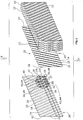
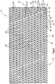
- Fig. 1 is a schematic and exploded view of a built-in element 10 in the form of a block of a plurality of obliquely corrugated grid mats 12, each grid mat as example in the FIGS. 2 or 3 shown in plan view, is configured.
- Each grid mat 12 has an oblique curvature of elevations 14 or peaks and valleys 16 or troughs along which first grid struts 18 extend.
- Adjacent elevations 14 and depressions 16 are connected to each other by flanks 19, wherein the installation element 10 is used, for example, according to the countercurrent principle by the fluid to be treated in the direction of arrow A (eg from bottom to top) through the mounting element 10 and the working fluid in Counter direction (see arrow B and consequently in this case from top to bottom) flows.
- the grid mat 12 also has two substantially parallel, corrugated longitudinal edges 20 and two transversely extending, also corrugated and parallel transverse edges 22 thereto.
- the first lattice struts 18 extend substantially between the two longitudinal edges 20 and partly, namely in the corner regions, between a longitudinal edge 20 and a transverse edge 22.
- the lattice mats 12 also have second lattice struts 24, which run essentially parallel to the longitudinal edges.
- the second lattice struts 24 are wave-shaped, since they extend at an acute angle to the extensions of the elevations 14 and the recesses 16.
- the second lattice struts 24 are connected at nodes 26 to the first lattice struts 18, wherein these nodes 26 are arranged along an imaginary node line 28.
- the grid mat 12 has third grid struts 30 and fourth grid struts 32, which intersect.
- the third grid struts 30 are parallel relative to each other;
- the fourth lattice struts 32 extend parallel to each other.
- Their crossing points 34, 36 are arranged alternately on the flanks 19 and in the recesses 16 and the elevations 14. The crossing points 36, along the projections 14 and the recesses 16 coincide with the nodes 26 between the first and second lattice struts 18, 24 together.
- the first grid struts 18 may be interrupted.
- the first lattice struts 18 have interruption sections 38, which are each arranged between two adjacent intersection points 36 on the respective lattice struts 18.
- the lattice struts 18 are in their areas between a longitudinal edge 20 and the next-adjacent node line 28 (second lattice strut 24) with advantage all not interrupted.
- the relative placement of the break sections 38 is ultimately arbitrary, care being taken that such break sections 38 for adjacent first grid stays 18 are not disposed between the same adjacent node lines 28.
- FIGS. 2 and 3 are still "eyes" or annular openings 40 to recognize, which are relative to the mounting element, aligned and through which a pull or push rod extends through, which additionally holds the mounting element together.
- contact plates 42 with openings 44 and corresponding contact pads 46 are formed with pins 48, which serve the pin hole connection of adjacent grid mats 12.
Landscapes
- Physics & Mathematics (AREA)
- Thermal Sciences (AREA)
- Chemical & Material Sciences (AREA)
- Engineering & Computer Science (AREA)
- Organic Chemistry (AREA)
- Chemical Kinetics & Catalysis (AREA)
- Mechanical Engineering (AREA)
- General Engineering & Computer Science (AREA)
- Physical Or Chemical Processes And Apparatus (AREA)
Claims (10)
- Élément à encastrer pour un dispositif destiné au traitement d'un fluide, en particulier d'un gaz, en particulier destiné à l'humidification, au nettoyage et/ou au refroidissement au moyen d'un fluide de travail, avec :au moins une natte en treillis (12) ondulée, laquelle est pourvue de :- renfoncements (16) et de bosses (14) qui s'étendent de manière rectiligne et qui sont disposés en alternance les uns à côté des autres, avec des flancs (19) qui relient ces renfoncements (16) et ces bosses (14) ;- deux bordures longitudinales (20) qui sont, pour l'essentiel, parallèles l'une par rapport à l'autre, ainsi que deux bordures transversales (22) qui courent à la transversale de ces bordures longitudinales (20) ;- des premières traverses en treillis (18), lesquelles sont rectilignes et, pour l'essentiel, parallèles les unes par rapport aux autres, et lesquelles courent dans des angles qui ne sont pas égaux à 90°, aussi bien par rapport aux bordures longitudinales (20) que par rapport aux bordures transversales (22), et lesquelles premières traverses en treillis (18) s'étendent, en bas, le long des renfoncements (16) et, en haut, le long des bosses (14) ;- des deuxièmes traverses en treillis (24) en forme de vagues, lesquelles courent, pour l'essentiel, parallèlement aux bordures longitudinales (20) et lesquelles sont reliées avec les premières traverses en treillis (18), au niveau d'intersections (26) disposées le long de lignes d'intersection (28) qui sont conçues, pour l'essentiel, de manière droite ; et- des troisièmes traverses en treillis (30) en forme de vagues, lesquelles sont, pour l'essentiel, parallèles entre elles, ainsi que le cas échéant, des quatrièmes traverses en treillis (32) en forme de vagues, lesquelles sont, pour l'essentiel, également parallèles entre elles ;selon lequel ces troisièmes et, éventuellement, quatrièmes traverses en treillis (30, 32) sont reliées avec les premières traverses en treillis (18) et avec les deuxièmes traverses en treillis (24), au niveau des intersections (26) ;selon lequel les troisièmes traverses en treillis et les quatrièmes traverses en treillis (30, 32) sont en outre reliées entre elles au niveau de points d'intersection (34), lesquels sont disposés au niveau des flancs (19) qui se trouvent entre les renfoncements (16) et les bosses (14) ;caractérisé en ce que- chaque première traverse en treillis (18) présente au moins une section d'interruption (38) le long de leur extension entre les bordures longitudinales (20), ou entre une bordure longitudinale (20) et une bordure transversale (22) ; et- les sections d'interruption (38) des premières traverses en treillis (18) adjacentes sont disposées de manière latéralement décalées, et en particulier sans se chevaucher.
- Élément à encastrer selon la revendication 1, caractérisé en ce qu'une section d'interruption (38) d'une première traverse en treillis (18) s'étend entre deux intersections (26) qui sont contiguës le long de la traverse en treillis.
- Élément à encastrer selon la revendication 1 ou 2, caractérisé en ce que les sections d'interruption (38) des premières traverses en treillis (18) adjacentes sont décalées latéralement de la distance entre au moins deux intersections (26) contiguës qui se suivent le long d'une première traverse en treillis (18).
- Élément à encastrer selon l'une des revendications 1 à 3, caractérisé en ce que les intersections (26) sont disposées le long de lignes d'intersection (28) qui courent parallèlement aux bordures longitudinales (20).
- Élément à encastrer selon l'une des revendications 1 à 4, caractérisé en ce que des éléments de jonction à broche et à trou correspondants, destinés à la jonction mécanique des nattes en treillis (12) contiguës, sont conçus le long des bordures longitudinales (20), ainsi qu'au niveau des intersections (26) mêmes qui sont disposées le long d'au moins deux lignes d'intersection (28), disposées entre les bordures longitudinales (20), et qui courent à la parallèle de celles-ci.
- Élément à encastrer selon l'une des revendications 1 à 5, caractérisé en ce que les sections d'interruption (38) des premières traverses en treillis (18) sont disposées le long de zones en forme de bande qui courent dans un angle aigu par rapport aux bordures longitudinales et transversales (20, 22).
- Élément à encastrer selon l'une des revendications 1 à 6, caractérisé en ce que chaque première traverse en treillis (18) présente une seule et unique section d'interruption (38).
- Élément à encastrer selon l'une des revendications 1 à 6, caractérisé en ce que chaque première traverse en treillis (18) présente deux ou trois sections d'interruption (38).
- Élément à encastrer selon l'une des revendications 1 à 6, caractérisé en ce que chaque première traverse en treillis (18) présente une, deux ou trois sections d'interruption (38) ;
selon lequel des premières traverses en treillis (18) adjacentes présentent un nombre identique ou différent de sections d'interruption (38) ; et/ou
caractérisé en ce que des premières traverses en treillis (18) sont réalisées avec une section d'interruption (38) et des premières traverses en treillis (18) sont réalisées avec deux sections d'interruption (38) ; et/ou
caractérisé en ce que des premières traverses en treillis (18) sont réalisées avec une section d'interruption (38) et des premières traverses en treillis (18) sont réalisées avec trois sections d'interruption (38) ; et/ou
caractérisé en ce que des premières traverses en treillis (18) sont réalisées avec deux sections d'interruption (38) et des premières traverses en treillis (18) sont réalisées avec trois sections d'interruption (38) ; et/ou
caractérisé en ce que des premières traverses en treillis (18) sont réalisées avec une section d'interruption (38), des premières traverses en treillis (18) sont réalisées avec deux sections d'interruption (38) et des traverses en treillis (18) sont réalisées avec trois sections d'interruption (38). - Élément à encastrer selon l'une des revendications 1 à 9, caractérisé en ce que les sections d'interruption (38) des premières traverses en treillis (18) sont disposées à l'extérieur des zones mêmes d'extension longitudinales de ces premières traverses en treillis (18) qui se trouvent entre une bordure longitudinale (20) ou une bordure transversale (22) et l'intersection (26) étant située respectivement la plus proche le long de la première traverse en treillis (18).
Applications Claiming Priority (1)
| Application Number | Priority Date | Filing Date | Title |
|---|---|---|---|
| DE102013225145.9A DE102013225145B4 (de) | 2013-12-06 | 2013-12-06 | Einbauelement für eine Vorrichtung zur Behandlung eines Fluids |
Publications (2)
| Publication Number | Publication Date |
|---|---|
| EP2881170A1 EP2881170A1 (fr) | 2015-06-10 |
| EP2881170B1 true EP2881170B1 (fr) | 2017-11-29 |
Family
ID=52021027
Family Applications (1)
| Application Number | Title | Priority Date | Filing Date |
|---|---|---|---|
| EP14196792.7A Active EP2881170B1 (fr) | 2013-12-06 | 2014-12-08 | Élément d'installation pour un dispositif de traitement d'un fluide |
Country Status (2)
| Country | Link |
|---|---|
| EP (1) | EP2881170B1 (fr) |
| DE (1) | DE102013225145B4 (fr) |
Families Citing this family (1)
| Publication number | Priority date | Publication date | Assignee | Title |
|---|---|---|---|---|
| EP4495532B1 (fr) | 2023-07-19 | 2026-02-11 | Hewitech GmbH & Co. KG | Treillis ondulé |
Family Cites Families (5)
| Publication number | Priority date | Publication date | Assignee | Title |
|---|---|---|---|---|
| DE19733480C2 (de) * | 1997-08-01 | 1999-06-24 | Gea Kuehlturmbau Gmbh | Einbaupackung zum Stoff- und/oder Wärmeaustausch zwischen Gasen und Flüssigkeiten |
| DE102005051882B4 (de) * | 2005-10-29 | 2007-08-02 | Hewitech Gmbh & Co. Kg | Einbauelement für einen Wärmetauscher oder zum Einbau im Erdreich zu Drainagezwecken |
| DE102006005112A1 (de) * | 2006-02-04 | 2007-08-09 | Hewitech Gmbh & Co. Kg | Kunststofflage für ein Einbauelement zum Einbau in einem Riesenkühler, insbesondere Kühlturm zu Kühlzwecken oder zum Einbau ins Erdreich zu Drainagezwecken |
| DE202009004513U1 (de) * | 2009-03-31 | 2009-07-16 | Dewath, Michael | Gitterplatten mit Abstandshaltern |
| DE102009052045A1 (de) * | 2009-11-05 | 2011-05-12 | Rvt Process Equipment Gmbh | Gewelltes Packungsgitter sowie geordnete, aus mehreren Packungsgittern aufgebaute Packung |
-
2013
- 2013-12-06 DE DE102013225145.9A patent/DE102013225145B4/de not_active Expired - Fee Related
-
2014
- 2014-12-08 EP EP14196792.7A patent/EP2881170B1/fr active Active
Non-Patent Citations (1)
| Title |
|---|
| None * |
Also Published As
| Publication number | Publication date |
|---|---|
| DE102013225145B4 (de) | 2015-07-09 |
| DE102013225145A1 (de) | 2015-06-11 |
| EP2881170A1 (fr) | 2015-06-10 |
Similar Documents
| Publication | Publication Date | Title |
|---|---|---|
| DE19733480C2 (de) | Einbaupackung zum Stoff- und/oder Wärmeaustausch zwischen Gasen und Flüssigkeiten | |
| EP2496342B1 (fr) | Grille de garniture ondulée et garniture ordonnée, constituée de plusieurs grilles de garniture | |
| EP2310756B1 (fr) | Élément intégrable à intégrer dans un dispositif d'humidification, de nettoyage et/ou de refroidissement d'un fluide, en particulier d'un gaz comme l'air par exemple, et procédé de fabrication d'un corps intégrable avec un tel élément intégrable | |
| EP3690378B1 (fr) | Moyen de montage pour un dispositif de traitement d'un fluide utile au moyen d'un fluide de travail | |
| EP3433544B1 (fr) | Module à insérer dans un dispositif d'humidification, de purification et/ou de refroidissement d'un fluide, en particulier d'un gaz comme l'air par exemple | |
| EP2881170B1 (fr) | Élément d'installation pour un dispositif de traitement d'un fluide | |
| EP3583360B1 (fr) | Corps coulants | |
| EP3049748A1 (fr) | Moyen de montage d'un dispositif de traitement d'un fluide de service et procédé de fabrication d'un tel moyen de montage | |
| EP3535539B1 (fr) | Moyen de montage pour un dispositif de traitement d'un fluide utile à l'aide d'un fluide de travail | |
| DE69416544T2 (de) | Packung und Verfahren zur Fertigung einer Packung | |
| DE102005051882B4 (de) | Einbauelement für einen Wärmetauscher oder zum Einbau im Erdreich zu Drainagezwecken | |
| DE29613862U1 (de) | Einbauelement für Wärmetauscher | |
| DE202013009854U1 (de) | Einbauelement für eine Vorrichtung zur Behandlung eines Fluids | |
| EP2881694B1 (fr) | Dispositif de montage pour un dispositif de traitement d'un fluide d'écoulement | |
| DE2312649B2 (de) | Waerme- und/oder massenaustauscher mit unmittelbarem kontakt einer fluessigkeit und eines gases | |
| EP4495532B1 (fr) | Treillis ondulé | |
| EP2853852B1 (fr) | Elément d'intégration pour un dispositif de traitement d'un fluide utile au moyen d'un fluide de travail | |
| DE1948282B2 (de) | Wabenkorper zum Behandeln von Flüssigkeiten mittels Gasen | |
| DE202013009855U1 (de) | Einbaueinrichtung für eine Vorrichtung zur Behandlung eines strömenden Fluids | |
| WO2010112005A2 (fr) | Plaques à grille présentant des éléments d'écartement | |
| WO2017174494A1 (fr) | Moyen de montage d'un dispositif de traitement d'un gaz avec un fluide de travail | |
| DE102013219779B4 (de) | Auflagervorrichtung für Tropfkörpereinbauten | |
| DE202016002100U1 (de) | Einbaueinrichtung für eine Vorrichtung zur Behandlung eines Gases mit einem Arbeitsfluid | |
| DE102017103178A1 (de) | Vorrichtung zur Befeuchtung, Reinigung und/oder Kühlung eines Gases, insbesondere von Luft | |
| DE102004025333A1 (de) | Vorrichtung zum Verbinden von nebeneinander angeordneten von einem Fluid durchströmbaren Einbauelementen |
Legal Events
| Date | Code | Title | Description |
|---|---|---|---|
| PUAI | Public reference made under article 153(3) epc to a published international application that has entered the european phase |
Free format text: ORIGINAL CODE: 0009012 |
|
| 17P | Request for examination filed |
Effective date: 20141208 |
|
| AK | Designated contracting states |
Kind code of ref document: A1 Designated state(s): AL AT BE BG CH CY CZ DE DK EE ES FI FR GB GR HR HU IE IS IT LI LT LU LV MC MK MT NL NO PL PT RO RS SE SI SK SM TR |
|
| AX | Request for extension of the european patent |
Extension state: BA ME |
|
| R17P | Request for examination filed (corrected) |
Effective date: 20151208 |
|
| RBV | Designated contracting states (corrected) |
Designated state(s): AL AT BE BG CH CY CZ DE DK EE ES FI FR GB GR HR HU IE IS IT LI LT LU LV MC MK MT NL NO PL PT RO RS SE SI SK SM TR |
|
| 17Q | First examination report despatched |
Effective date: 20160517 |
|
| GRAP | Despatch of communication of intention to grant a patent |
Free format text: ORIGINAL CODE: EPIDOSNIGR1 |
|
| STAA | Information on the status of an ep patent application or granted ep patent |
Free format text: STATUS: GRANT OF PATENT IS INTENDED |
|
| INTG | Intention to grant announced |
Effective date: 20170512 |
|
| GRAJ | Information related to disapproval of communication of intention to grant by the applicant or resumption of examination proceedings by the epo deleted |
Free format text: ORIGINAL CODE: EPIDOSDIGR1 |
|
| GRAL | Information related to payment of fee for publishing/printing deleted |
Free format text: ORIGINAL CODE: EPIDOSDIGR3 |
|
| GRAS | Grant fee paid |
Free format text: ORIGINAL CODE: EPIDOSNIGR3 |
|
| STAA | Information on the status of an ep patent application or granted ep patent |
Free format text: STATUS: EXAMINATION IS IN PROGRESS |
|
| GRAP | Despatch of communication of intention to grant a patent |
Free format text: ORIGINAL CODE: EPIDOSNIGR1 |
|
| STAA | Information on the status of an ep patent application or granted ep patent |
Free format text: STATUS: GRANT OF PATENT IS INTENDED |
|
| GRAA | (expected) grant |
Free format text: ORIGINAL CODE: 0009210 |
|
| STAA | Information on the status of an ep patent application or granted ep patent |
Free format text: STATUS: THE PATENT HAS BEEN GRANTED |
|
| INTC | Intention to grant announced (deleted) | ||
| INTG | Intention to grant announced |
Effective date: 20171016 |
|
| AK | Designated contracting states |
Kind code of ref document: B1 Designated state(s): AL AT BE BG CH CY CZ DE DK EE ES FI FR GB GR HR HU IE IS IT LI LT LU LV MC MK MT NL NO PL PT RO RS SE SI SK SM TR |
|
| REG | Reference to a national code |
Ref country code: CH Ref legal event code: EP |
|
| REG | Reference to a national code |
Ref country code: AT Ref legal event code: REF Ref document number: 949887 Country of ref document: AT Kind code of ref document: T Effective date: 20171215 |
|
| REG | Reference to a national code |
Ref country code: IE Ref legal event code: FG4D Free format text: LANGUAGE OF EP DOCUMENT: GERMAN |
|
| REG | Reference to a national code |
Ref country code: DE Ref legal event code: R096 Ref document number: 502014006393 Country of ref document: DE |
|
| REG | Reference to a national code |
Ref country code: NL Ref legal event code: MP Effective date: 20171129 |
|
| REG | Reference to a national code |
Ref country code: LT Ref legal event code: MG4D |
|
| PG25 | Lapsed in a contracting state [announced via postgrant information from national office to epo] |
Ref country code: FI Free format text: LAPSE BECAUSE OF FAILURE TO SUBMIT A TRANSLATION OF THE DESCRIPTION OR TO PAY THE FEE WITHIN THE PRESCRIBED TIME-LIMIT Effective date: 20171129 Ref country code: SE Free format text: LAPSE BECAUSE OF FAILURE TO SUBMIT A TRANSLATION OF THE DESCRIPTION OR TO PAY THE FEE WITHIN THE PRESCRIBED TIME-LIMIT Effective date: 20171129 Ref country code: ES Free format text: LAPSE BECAUSE OF FAILURE TO SUBMIT A TRANSLATION OF THE DESCRIPTION OR TO PAY THE FEE WITHIN THE PRESCRIBED TIME-LIMIT Effective date: 20171129 Ref country code: LT Free format text: LAPSE BECAUSE OF FAILURE TO SUBMIT A TRANSLATION OF THE DESCRIPTION OR TO PAY THE FEE WITHIN THE PRESCRIBED TIME-LIMIT Effective date: 20171129 Ref country code: NO Free format text: LAPSE BECAUSE OF FAILURE TO SUBMIT A TRANSLATION OF THE DESCRIPTION OR TO PAY THE FEE WITHIN THE PRESCRIBED TIME-LIMIT Effective date: 20180228 |
|
| PG25 | Lapsed in a contracting state [announced via postgrant information from national office to epo] |
Ref country code: BG Free format text: LAPSE BECAUSE OF FAILURE TO SUBMIT A TRANSLATION OF THE DESCRIPTION OR TO PAY THE FEE WITHIN THE PRESCRIBED TIME-LIMIT Effective date: 20180228 Ref country code: RS Free format text: LAPSE BECAUSE OF FAILURE TO SUBMIT A TRANSLATION OF THE DESCRIPTION OR TO PAY THE FEE WITHIN THE PRESCRIBED TIME-LIMIT Effective date: 20171129 Ref country code: HR Free format text: LAPSE BECAUSE OF FAILURE TO SUBMIT A TRANSLATION OF THE DESCRIPTION OR TO PAY THE FEE WITHIN THE PRESCRIBED TIME-LIMIT Effective date: 20171129 Ref country code: LV Free format text: LAPSE BECAUSE OF FAILURE TO SUBMIT A TRANSLATION OF THE DESCRIPTION OR TO PAY THE FEE WITHIN THE PRESCRIBED TIME-LIMIT Effective date: 20171129 Ref country code: GR Free format text: LAPSE BECAUSE OF FAILURE TO SUBMIT A TRANSLATION OF THE DESCRIPTION OR TO PAY THE FEE WITHIN THE PRESCRIBED TIME-LIMIT Effective date: 20180301 |
|
| PG25 | Lapsed in a contracting state [announced via postgrant information from national office to epo] |
Ref country code: NL Free format text: LAPSE BECAUSE OF FAILURE TO SUBMIT A TRANSLATION OF THE DESCRIPTION OR TO PAY THE FEE WITHIN THE PRESCRIBED TIME-LIMIT Effective date: 20171129 |
|
| PG25 | Lapsed in a contracting state [announced via postgrant information from national office to epo] |
Ref country code: SK Free format text: LAPSE BECAUSE OF FAILURE TO SUBMIT A TRANSLATION OF THE DESCRIPTION OR TO PAY THE FEE WITHIN THE PRESCRIBED TIME-LIMIT Effective date: 20171129 Ref country code: CZ Free format text: LAPSE BECAUSE OF FAILURE TO SUBMIT A TRANSLATION OF THE DESCRIPTION OR TO PAY THE FEE WITHIN THE PRESCRIBED TIME-LIMIT Effective date: 20171129 Ref country code: CY Free format text: LAPSE BECAUSE OF FAILURE TO SUBMIT A TRANSLATION OF THE DESCRIPTION OR TO PAY THE FEE WITHIN THE PRESCRIBED TIME-LIMIT Effective date: 20171129 Ref country code: EE Free format text: LAPSE BECAUSE OF FAILURE TO SUBMIT A TRANSLATION OF THE DESCRIPTION OR TO PAY THE FEE WITHIN THE PRESCRIBED TIME-LIMIT Effective date: 20171129 Ref country code: DK Free format text: LAPSE BECAUSE OF FAILURE TO SUBMIT A TRANSLATION OF THE DESCRIPTION OR TO PAY THE FEE WITHIN THE PRESCRIBED TIME-LIMIT Effective date: 20171129 |
|
| REG | Reference to a national code |
Ref country code: CH Ref legal event code: PL |
|
| REG | Reference to a national code |
Ref country code: DE Ref legal event code: R097 Ref document number: 502014006393 Country of ref document: DE |
|
| PG25 | Lapsed in a contracting state [announced via postgrant information from national office to epo] |
Ref country code: RO Free format text: LAPSE BECAUSE OF FAILURE TO SUBMIT A TRANSLATION OF THE DESCRIPTION OR TO PAY THE FEE WITHIN THE PRESCRIBED TIME-LIMIT Effective date: 20171129 Ref country code: SM Free format text: LAPSE BECAUSE OF FAILURE TO SUBMIT A TRANSLATION OF THE DESCRIPTION OR TO PAY THE FEE WITHIN THE PRESCRIBED TIME-LIMIT Effective date: 20171129 Ref country code: PL Free format text: LAPSE BECAUSE OF FAILURE TO SUBMIT A TRANSLATION OF THE DESCRIPTION OR TO PAY THE FEE WITHIN THE PRESCRIBED TIME-LIMIT Effective date: 20171129 Ref country code: IT Free format text: LAPSE BECAUSE OF FAILURE TO SUBMIT A TRANSLATION OF THE DESCRIPTION OR TO PAY THE FEE WITHIN THE PRESCRIBED TIME-LIMIT Effective date: 20171129 |
|
| REG | Reference to a national code |
Ref country code: IE Ref legal event code: MM4A |
|
| PG25 | Lapsed in a contracting state [announced via postgrant information from national office to epo] |
Ref country code: LU Free format text: LAPSE BECAUSE OF NON-PAYMENT OF DUE FEES Effective date: 20171208 Ref country code: MT Free format text: LAPSE BECAUSE OF FAILURE TO SUBMIT A TRANSLATION OF THE DESCRIPTION OR TO PAY THE FEE WITHIN THE PRESCRIBED TIME-LIMIT Effective date: 20171129 |
|
| PLBE | No opposition filed within time limit |
Free format text: ORIGINAL CODE: 0009261 |
|
| STAA | Information on the status of an ep patent application or granted ep patent |
Free format text: STATUS: NO OPPOSITION FILED WITHIN TIME LIMIT |
|
| REG | Reference to a national code |
Ref country code: BE Ref legal event code: MM Effective date: 20171231 |
|
| PG25 | Lapsed in a contracting state [announced via postgrant information from national office to epo] |
Ref country code: IE Free format text: LAPSE BECAUSE OF NON-PAYMENT OF DUE FEES Effective date: 20171208 |
|
| 26N | No opposition filed |
Effective date: 20180830 |
|
| PG25 | Lapsed in a contracting state [announced via postgrant information from national office to epo] |
Ref country code: SI Free format text: LAPSE BECAUSE OF FAILURE TO SUBMIT A TRANSLATION OF THE DESCRIPTION OR TO PAY THE FEE WITHIN THE PRESCRIBED TIME-LIMIT Effective date: 20171129 Ref country code: LI Free format text: LAPSE BECAUSE OF NON-PAYMENT OF DUE FEES Effective date: 20171231 Ref country code: CH Free format text: LAPSE BECAUSE OF NON-PAYMENT OF DUE FEES Effective date: 20171231 Ref country code: BE Free format text: LAPSE BECAUSE OF NON-PAYMENT OF DUE FEES Effective date: 20171231 |
|
| REG | Reference to a national code |
Ref country code: FR Ref legal event code: ST Effective date: 20181102 |
|
| PG25 | Lapsed in a contracting state [announced via postgrant information from national office to epo] |
Ref country code: FR Free format text: LAPSE BECAUSE OF NON-PAYMENT OF DUE FEES Effective date: 20180129 |
|
| PG25 | Lapsed in a contracting state [announced via postgrant information from national office to epo] |
Ref country code: HU Free format text: LAPSE BECAUSE OF FAILURE TO SUBMIT A TRANSLATION OF THE DESCRIPTION OR TO PAY THE FEE WITHIN THE PRESCRIBED TIME-LIMIT; INVALID AB INITIO Effective date: 20141208 Ref country code: MC Free format text: LAPSE BECAUSE OF FAILURE TO SUBMIT A TRANSLATION OF THE DESCRIPTION OR TO PAY THE FEE WITHIN THE PRESCRIBED TIME-LIMIT Effective date: 20171129 |
|
| GBPC | Gb: european patent ceased through non-payment of renewal fee |
Effective date: 20181208 |
|
| PG25 | Lapsed in a contracting state [announced via postgrant information from national office to epo] |
Ref country code: MK Free format text: LAPSE BECAUSE OF FAILURE TO SUBMIT A TRANSLATION OF THE DESCRIPTION OR TO PAY THE FEE WITHIN THE PRESCRIBED TIME-LIMIT Effective date: 20171129 |
|
| PG25 | Lapsed in a contracting state [announced via postgrant information from national office to epo] |
Ref country code: GB Free format text: LAPSE BECAUSE OF NON-PAYMENT OF DUE FEES Effective date: 20181208 |
|
| PG25 | Lapsed in a contracting state [announced via postgrant information from national office to epo] |
Ref country code: TR Free format text: LAPSE BECAUSE OF FAILURE TO SUBMIT A TRANSLATION OF THE DESCRIPTION OR TO PAY THE FEE WITHIN THE PRESCRIBED TIME-LIMIT Effective date: 20171129 |
|
| PG25 | Lapsed in a contracting state [announced via postgrant information from national office to epo] |
Ref country code: PT Free format text: LAPSE BECAUSE OF FAILURE TO SUBMIT A TRANSLATION OF THE DESCRIPTION OR TO PAY THE FEE WITHIN THE PRESCRIBED TIME-LIMIT Effective date: 20171129 |
|
| PG25 | Lapsed in a contracting state [announced via postgrant information from national office to epo] |
Ref country code: AL Free format text: LAPSE BECAUSE OF FAILURE TO SUBMIT A TRANSLATION OF THE DESCRIPTION OR TO PAY THE FEE WITHIN THE PRESCRIBED TIME-LIMIT Effective date: 20171129 Ref country code: IS Free format text: LAPSE BECAUSE OF FAILURE TO SUBMIT A TRANSLATION OF THE DESCRIPTION OR TO PAY THE FEE WITHIN THE PRESCRIBED TIME-LIMIT Effective date: 20180329 |
|
| REG | Reference to a national code |
Ref country code: AT Ref legal event code: MM01 Ref document number: 949887 Country of ref document: AT Kind code of ref document: T Effective date: 20191208 |
|
| PG25 | Lapsed in a contracting state [announced via postgrant information from national office to epo] |
Ref country code: AT Free format text: LAPSE BECAUSE OF NON-PAYMENT OF DUE FEES Effective date: 20191208 |
|
| P01 | Opt-out of the competence of the unified patent court (upc) registered |
Effective date: 20230524 |
|
| PGFP | Annual fee paid to national office [announced via postgrant information from national office to epo] |
Ref country code: DE Payment date: 20251117 Year of fee payment: 12 |