EP2451378B1 - Vascular and bodily duct treatment devices - Google Patents
Vascular and bodily duct treatment devices Download PDFInfo
- Publication number
- EP2451378B1 EP2451378B1 EP10797880.1A EP10797880A EP2451378B1 EP 2451378 B1 EP2451378 B1 EP 2451378B1 EP 10797880 A EP10797880 A EP 10797880A EP 2451378 B1 EP2451378 B1 EP 2451378B1
- Authority
- EP
- European Patent Office
- Prior art keywords
- expandable member
- main body
- body portion
- proximal end
- cell structures
- Prior art date
- Legal status (The legal status is an assumption and is not a legal conclusion. Google has not performed a legal analysis and makes no representation as to the accuracy of the status listed.)
- Active
Links
Images


Classifications
-
- A—HUMAN NECESSITIES
- A61—MEDICAL OR VETERINARY SCIENCE; HYGIENE
- A61F—FILTERS IMPLANTABLE INTO BLOOD VESSELS; PROSTHESES; DEVICES PROVIDING PATENCY TO, OR PREVENTING COLLAPSING OF, TUBULAR STRUCTURES OF THE BODY, e.g. STENTS; ORTHOPAEDIC, NURSING OR CONTRACEPTIVE DEVICES; FOMENTATION; TREATMENT OR PROTECTION OF EYES OR EARS; BANDAGES, DRESSINGS OR ABSORBENT PADS; FIRST-AID KITS
- A61F2/00—Filters implantable into blood vessels; Prostheses, i.e. artificial substitutes or replacements for parts of the body; Appliances for connecting them with the body; Devices providing patency to, or preventing collapsing of, tubular structures of the body, e.g. stents
- A61F2/82—Devices providing patency to, or preventing collapsing of, tubular structures of the body, e.g. stents
- A61F2/86—Stents in a form characterised by the wire-like elements; Stents in the form characterised by a net-like or mesh-like structure
- A61F2/90—Stents in a form characterised by the wire-like elements; Stents in the form characterised by a net-like or mesh-like structure characterised by a net-like or mesh-like structure
- A61F2/91—Stents in a form characterised by the wire-like elements; Stents in the form characterised by a net-like or mesh-like structure characterised by a net-like or mesh-like structure made from perforated sheets or tubes, e.g. perforated by laser cuts or etched holes
- A61F2/915—Stents in a form characterised by the wire-like elements; Stents in the form characterised by a net-like or mesh-like structure characterised by a net-like or mesh-like structure made from perforated sheets or tubes, e.g. perforated by laser cuts or etched holes with bands having a meander structure, adjacent bands being connected to each other
-
- A—HUMAN NECESSITIES
- A61—MEDICAL OR VETERINARY SCIENCE; HYGIENE
- A61F—FILTERS IMPLANTABLE INTO BLOOD VESSELS; PROSTHESES; DEVICES PROVIDING PATENCY TO, OR PREVENTING COLLAPSING OF, TUBULAR STRUCTURES OF THE BODY, e.g. STENTS; ORTHOPAEDIC, NURSING OR CONTRACEPTIVE DEVICES; FOMENTATION; TREATMENT OR PROTECTION OF EYES OR EARS; BANDAGES, DRESSINGS OR ABSORBENT PADS; FIRST-AID KITS
- A61F2/00—Filters implantable into blood vessels; Prostheses, i.e. artificial substitutes or replacements for parts of the body; Appliances for connecting them with the body; Devices providing patency to, or preventing collapsing of, tubular structures of the body, e.g. stents
- A61F2/02—Prostheses implantable into the body
- A61F2/04—Hollow or tubular parts of organs, e.g. bladders, tracheae, bronchi or bile ducts
- A61F2/06—Blood vessels
-
- A—HUMAN NECESSITIES
- A61—MEDICAL OR VETERINARY SCIENCE; HYGIENE
- A61F—FILTERS IMPLANTABLE INTO BLOOD VESSELS; PROSTHESES; DEVICES PROVIDING PATENCY TO, OR PREVENTING COLLAPSING OF, TUBULAR STRUCTURES OF THE BODY, e.g. STENTS; ORTHOPAEDIC, NURSING OR CONTRACEPTIVE DEVICES; FOMENTATION; TREATMENT OR PROTECTION OF EYES OR EARS; BANDAGES, DRESSINGS OR ABSORBENT PADS; FIRST-AID KITS
- A61F2/00—Filters implantable into blood vessels; Prostheses, i.e. artificial substitutes or replacements for parts of the body; Appliances for connecting them with the body; Devices providing patency to, or preventing collapsing of, tubular structures of the body, e.g. stents
- A61F2/95—Instruments specially adapted for placement or removal of stents or stent-grafts
-
- A—HUMAN NECESSITIES
- A61—MEDICAL OR VETERINARY SCIENCE; HYGIENE
- A61F—FILTERS IMPLANTABLE INTO BLOOD VESSELS; PROSTHESES; DEVICES PROVIDING PATENCY TO, OR PREVENTING COLLAPSING OF, TUBULAR STRUCTURES OF THE BODY, e.g. STENTS; ORTHOPAEDIC, NURSING OR CONTRACEPTIVE DEVICES; FOMENTATION; TREATMENT OR PROTECTION OF EYES OR EARS; BANDAGES, DRESSINGS OR ABSORBENT PADS; FIRST-AID KITS
- A61F2/00—Filters implantable into blood vessels; Prostheses, i.e. artificial substitutes or replacements for parts of the body; Appliances for connecting them with the body; Devices providing patency to, or preventing collapsing of, tubular structures of the body, e.g. stents
- A61F2/01—Filters implantable into blood vessels
- A61F2/013—Distal protection devices, i.e. devices placed distally in combination with another endovascular procedure, e.g. angioplasty or stenting
-
- A—HUMAN NECESSITIES
- A61—MEDICAL OR VETERINARY SCIENCE; HYGIENE
- A61F—FILTERS IMPLANTABLE INTO BLOOD VESSELS; PROSTHESES; DEVICES PROVIDING PATENCY TO, OR PREVENTING COLLAPSING OF, TUBULAR STRUCTURES OF THE BODY, e.g. STENTS; ORTHOPAEDIC, NURSING OR CONTRACEPTIVE DEVICES; FOMENTATION; TREATMENT OR PROTECTION OF EYES OR EARS; BANDAGES, DRESSINGS OR ABSORBENT PADS; FIRST-AID KITS
- A61F2/00—Filters implantable into blood vessels; Prostheses, i.e. artificial substitutes or replacements for parts of the body; Appliances for connecting them with the body; Devices providing patency to, or preventing collapsing of, tubular structures of the body, e.g. stents
- A61F2/82—Devices providing patency to, or preventing collapsing of, tubular structures of the body, e.g. stents
- A61F2/86—Stents in a form characterised by the wire-like elements; Stents in the form characterised by a net-like or mesh-like structure
- A61F2/88—Stents in a form characterised by the wire-like elements; Stents in the form characterised by a net-like or mesh-like structure the wire-like elements formed as helical or spiral coils
-
- A—HUMAN NECESSITIES
- A61—MEDICAL OR VETERINARY SCIENCE; HYGIENE
- A61F—FILTERS IMPLANTABLE INTO BLOOD VESSELS; PROSTHESES; DEVICES PROVIDING PATENCY TO, OR PREVENTING COLLAPSING OF, TUBULAR STRUCTURES OF THE BODY, e.g. STENTS; ORTHOPAEDIC, NURSING OR CONTRACEPTIVE DEVICES; FOMENTATION; TREATMENT OR PROTECTION OF EYES OR EARS; BANDAGES, DRESSINGS OR ABSORBENT PADS; FIRST-AID KITS
- A61F2/00—Filters implantable into blood vessels; Prostheses, i.e. artificial substitutes or replacements for parts of the body; Appliances for connecting them with the body; Devices providing patency to, or preventing collapsing of, tubular structures of the body, e.g. stents
- A61F2/01—Filters implantable into blood vessels
- A61F2002/018—Filters implantable into blood vessels made from tubes or sheets of material, e.g. by etching or laser-cutting
-
- A—HUMAN NECESSITIES
- A61—MEDICAL OR VETERINARY SCIENCE; HYGIENE
- A61F—FILTERS IMPLANTABLE INTO BLOOD VESSELS; PROSTHESES; DEVICES PROVIDING PATENCY TO, OR PREVENTING COLLAPSING OF, TUBULAR STRUCTURES OF THE BODY, e.g. STENTS; ORTHOPAEDIC, NURSING OR CONTRACEPTIVE DEVICES; FOMENTATION; TREATMENT OR PROTECTION OF EYES OR EARS; BANDAGES, DRESSINGS OR ABSORBENT PADS; FIRST-AID KITS
- A61F2/00—Filters implantable into blood vessels; Prostheses, i.e. artificial substitutes or replacements for parts of the body; Appliances for connecting them with the body; Devices providing patency to, or preventing collapsing of, tubular structures of the body, e.g. stents
- A61F2/82—Devices providing patency to, or preventing collapsing of, tubular structures of the body, e.g. stents
- A61F2002/825—Devices providing patency to, or preventing collapsing of, tubular structures of the body, e.g. stents having longitudinal struts
-
- A—HUMAN NECESSITIES
- A61—MEDICAL OR VETERINARY SCIENCE; HYGIENE
- A61F—FILTERS IMPLANTABLE INTO BLOOD VESSELS; PROSTHESES; DEVICES PROVIDING PATENCY TO, OR PREVENTING COLLAPSING OF, TUBULAR STRUCTURES OF THE BODY, e.g. STENTS; ORTHOPAEDIC, NURSING OR CONTRACEPTIVE DEVICES; FOMENTATION; TREATMENT OR PROTECTION OF EYES OR EARS; BANDAGES, DRESSINGS OR ABSORBENT PADS; FIRST-AID KITS
- A61F2/00—Filters implantable into blood vessels; Prostheses, i.e. artificial substitutes or replacements for parts of the body; Appliances for connecting them with the body; Devices providing patency to, or preventing collapsing of, tubular structures of the body, e.g. stents
- A61F2/95—Instruments specially adapted for placement or removal of stents or stent-grafts
- A61F2002/9528—Instruments specially adapted for placement or removal of stents or stent-grafts for retrieval of stents
-
- A—HUMAN NECESSITIES
- A61—MEDICAL OR VETERINARY SCIENCE; HYGIENE
- A61F—FILTERS IMPLANTABLE INTO BLOOD VESSELS; PROSTHESES; DEVICES PROVIDING PATENCY TO, OR PREVENTING COLLAPSING OF, TUBULAR STRUCTURES OF THE BODY, e.g. STENTS; ORTHOPAEDIC, NURSING OR CONTRACEPTIVE DEVICES; FOMENTATION; TREATMENT OR PROTECTION OF EYES OR EARS; BANDAGES, DRESSINGS OR ABSORBENT PADS; FIRST-AID KITS
- A61F2/00—Filters implantable into blood vessels; Prostheses, i.e. artificial substitutes or replacements for parts of the body; Appliances for connecting them with the body; Devices providing patency to, or preventing collapsing of, tubular structures of the body, e.g. stents
- A61F2/95—Instruments specially adapted for placement or removal of stents or stent-grafts
- A61F2002/9534—Instruments specially adapted for placement or removal of stents or stent-grafts for repositioning of stents
-
- A—HUMAN NECESSITIES
- A61—MEDICAL OR VETERINARY SCIENCE; HYGIENE
- A61F—FILTERS IMPLANTABLE INTO BLOOD VESSELS; PROSTHESES; DEVICES PROVIDING PATENCY TO, OR PREVENTING COLLAPSING OF, TUBULAR STRUCTURES OF THE BODY, e.g. STENTS; ORTHOPAEDIC, NURSING OR CONTRACEPTIVE DEVICES; FOMENTATION; TREATMENT OR PROTECTION OF EYES OR EARS; BANDAGES, DRESSINGS OR ABSORBENT PADS; FIRST-AID KITS
- A61F2220/00—Fixations or connections for prostheses classified in groups A61F2/00 - A61F2/26 or A61F2/82 or A61F9/00 or A61F11/00 or subgroups thereof
- A61F2220/0025—Connections or couplings between prosthetic parts, e.g. between modular parts; Connecting elements
- A61F2220/005—Connections or couplings between prosthetic parts, e.g. between modular parts; Connecting elements using adhesives
-
- A—HUMAN NECESSITIES
- A61—MEDICAL OR VETERINARY SCIENCE; HYGIENE
- A61F—FILTERS IMPLANTABLE INTO BLOOD VESSELS; PROSTHESES; DEVICES PROVIDING PATENCY TO, OR PREVENTING COLLAPSING OF, TUBULAR STRUCTURES OF THE BODY, e.g. STENTS; ORTHOPAEDIC, NURSING OR CONTRACEPTIVE DEVICES; FOMENTATION; TREATMENT OR PROTECTION OF EYES OR EARS; BANDAGES, DRESSINGS OR ABSORBENT PADS; FIRST-AID KITS
- A61F2220/00—Fixations or connections for prostheses classified in groups A61F2/00 - A61F2/26 or A61F2/82 or A61F9/00 or A61F11/00 or subgroups thereof
- A61F2220/0025—Connections or couplings between prosthetic parts, e.g. between modular parts; Connecting elements
- A61F2220/0058—Connections or couplings between prosthetic parts, e.g. between modular parts; Connecting elements soldered or brazed or welded
-
- A—HUMAN NECESSITIES
- A61—MEDICAL OR VETERINARY SCIENCE; HYGIENE
- A61F—FILTERS IMPLANTABLE INTO BLOOD VESSELS; PROSTHESES; DEVICES PROVIDING PATENCY TO, OR PREVENTING COLLAPSING OF, TUBULAR STRUCTURES OF THE BODY, e.g. STENTS; ORTHOPAEDIC, NURSING OR CONTRACEPTIVE DEVICES; FOMENTATION; TREATMENT OR PROTECTION OF EYES OR EARS; BANDAGES, DRESSINGS OR ABSORBENT PADS; FIRST-AID KITS
- A61F2230/00—Geometry of prostheses classified in groups A61F2/00 - A61F2/26 or A61F2/82 or A61F9/00 or A61F11/00 or subgroups thereof
- A61F2230/0002—Two-dimensional shapes, e.g. cross-sections
- A61F2230/0004—Rounded shapes, e.g. with rounded corners
- A61F2230/0008—Rounded shapes, e.g. with rounded corners elliptical or oval
-
- A—HUMAN NECESSITIES
- A61—MEDICAL OR VETERINARY SCIENCE; HYGIENE
- A61F—FILTERS IMPLANTABLE INTO BLOOD VESSELS; PROSTHESES; DEVICES PROVIDING PATENCY TO, OR PREVENTING COLLAPSING OF, TUBULAR STRUCTURES OF THE BODY, e.g. STENTS; ORTHOPAEDIC, NURSING OR CONTRACEPTIVE DEVICES; FOMENTATION; TREATMENT OR PROTECTION OF EYES OR EARS; BANDAGES, DRESSINGS OR ABSORBENT PADS; FIRST-AID KITS
- A61F2250/00—Special features of prostheses classified in groups A61F2/00 - A61F2/26 or A61F2/82 or A61F9/00 or A61F11/00 or subgroups thereof
- A61F2250/0014—Special features of prostheses classified in groups A61F2/00 - A61F2/26 or A61F2/82 or A61F9/00 or A61F11/00 or subgroups thereof having different values of a given property or geometrical feature, e.g. mechanical property or material property, at different locations within the same prosthesis
- A61F2250/0039—Special features of prostheses classified in groups A61F2/00 - A61F2/26 or A61F2/82 or A61F9/00 or A61F11/00 or subgroups thereof having different values of a given property or geometrical feature, e.g. mechanical property or material property, at different locations within the same prosthesis differing in diameter
Definitions
- This application relates to devices and methods for treating the vasculature and other ducts within the body.
- Self-expanding prostheses such as stents, covered stents, vascular grafts, flow diverters, and the like have been developed to treat ducts within the body. Many of the prostheses have been developed to treat blockages within the vasculature and also aneurysms that occur in the brain. What are needed are improved treatment methods and devices for treating the vasculature and other body ducts, such as, for example, aneurysms, stenoses, embolic obstructions, and the like.
- Document EP 1 867 290 describes a vascular thrombectomby apparatus and method of use.
- the present invention provides an embolic obstruction retrieval device in accordance with claim 1.
- embolic obstruction retrieval device in accordance with claim 1.
- Device 10 includes a self-expandable member 12 that is attached or otherwise coupled to an elongate flexible wire 40 that extends proximally from the expandable member 12.
- the expandable member 12 is made of shape memory material, such as Nitinol, and is preferably laser cut from a tube.
- the expandable member 12 has an integrally formed proximally extending wire segment 42 that is used to join the elongate flexible wire 40 to the expandable member 12.
- flexible wire 40 may be joined to wire segment 42 by the use of solder, a weld, an adhesive, or other known attachment method.
- the distal end of flexible wire 40 is attached directly to a proximal end 20 of the expandable member 12.
- the distal end of wire 40 has a flat profile with a width of about 0.127 mm (0.005 inches) with the width and thickness of the wire segment 42 being about 0.16 mm (0.0063 inches) and about 0.089 mm (0.0035 inches), respectively.
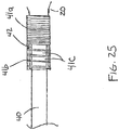
- the distal end of wire 40 is attached to the proximally extending wire segment 42 by the following method, resulting in the joint illustrated in Figure 25 .
- a coil 41 is positioned over wire segment 42, the coil having a closely wrapped segment 41a abutting the proximal end of expandable member 12, and a loosely wrapped segment 41b that includes one or more gaps 41c. The size of the one or more gaps 41c being sufficient to introduce a bonding agent into at least the inner cavity of coil segment 41b.
- the length of wire segment 42 and the coil 41 are equal. In one embodiment the length of the wire segment 42 is 4.0 millimeters with the coil 41 being of equal length.
- the distal end of wire 40 is placed within coil segment 41b so that it makes contact with and overlaps the proximal end portion of wire segment 42.
- a bonding agent is then applied through the gaps 41c of coil 41 to bond the wire 40 with wire segment 41.
- the bonding agent may be an adhesive, solder, or any other suitable bonding agent.
- the bonding agent is a solder
- a preceding step in the process involves coating the distal end portion of wire 40 and the proximal end portion of wire segment 42 with tin or another suitable wetting agent.
- the solder is gold and is used to enhance the radiopacity of the joint so that the joint may serve as a proximal radiopaque marker.
- all or portions of the coil may be made of a radiopaque material to further enhance the radiopacity of the joint.
- the length of overlap between the wire 40 and wire segment 42 is between 0.75 and 1.0 millimeters.
- the length of coil segment 41b is equal, or substantially equal, to the overlap length of the wire 40 and wire segment 42.
- two or more coils in abutting relationship are used with, for example, a first closely wound coil abutting the proximal end 20 of the expandable member 12 and a second loosely wound coil with gaps situated proximal to the closely wound coil.
- a distal end length of wire 40 is tapered in the distal direction from a nominal diameter to a reduced profile. Along this length is provided a distal wire coil of a constant outer diameter with no taper. In accordance with one implementation, the diameter of coil 41 has the same outer diameter as the distal wire coil.
- joint construction is that it is resistant to buckling while the device is being pushed through a delivery catheter while at the same time being sufficiently flexible to enable the device to be delivered through the tortuous anatomy of a patient.
- the joint is able to withstand high tensile and torque loads without breaking. Load test have shown the joint of the previously described embodiment can withstand in excess of 2 pounds (8.9 N) of tensile stress.
- coil 41 is made of a radiopaque material to also function as a proximal radiopaque marker.
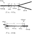
- Figure 28A depicts an alternative proximal wire segment construction.
- the proximal wire segment 4002 comprises a first section 4002a and a second section 4002b, with the second section 4002b having a width W greater than the width of the first section.
- a tapered transition section 4003 joins the first and second sections 4002a and 4002b.
- the width of the first section 4002a is about 0.16 mm (0.0063 inches) while the width W of the second section is between about 0.216 mm (0.0085 inches) and about 0.267 mm (0.0105 inches).
- the length L between the proximal end 4005 of the expandable member 4004 and second section 4002b of the wire segment 4002 is between about 0.432 mm (0.017 inches) and about 0.559 mm (0.022 inches).
- An advantage of the inclusion of the second section 4002b is that the greater width dimension provides a larger surface area for bonding the wire segment 4002 to the elongate wire 40 used in the delivery and retraction of the elongate member from a duct of a patient.
- the first section 4002a has a circular or substantially circular construction and the second section 4002b has a flat profile formed by a pressing/coining operation.
- expandable member 12 includes a plurality of generally longitudinal undulating elements 24 with adjacent undulating elements being out-of-phase with one another and connected in a manner to form a plurality of diagonally disposed cell structures 26.
- the expandable member 12 includes a proximal end portion 14, a cylindrical main body portion 16 and a distal end portion 18 with the cell structures 26 in the main body portion 16 extending continuously and circumferentially around a longitudinal axis 30 of the expandable member 12.
- the cell structures 26 in the proximal end portion 14 and distal end portion 18 extend less than circumferentially around the longitudinal axis 30 of the expandable member 12.
- expandable member 12 has an overall length of about 33.0 millimeters with the main body portion 16 measuring about 16.0 millimeters in length and the proximal and distal end portions 14 and 18 each measuring about 7.0 millimeters in length.
- the length of the main body portion 16 is generally between about 2.5 to about 3.5 times greater than the length of the proximal and distal end portions 14 and 18.
- expandable member 12 is advanced through the tortuous vascular anatomy or bodily duct of a patient to a treatment site in an unexpanded or compressed state (not shown) of a first nominal diameter and is movable from the unexpanded state to a radially expanded state of a second nominal diameter greater than the first nominal diameter for deployment at the treatment site.
- first nominal diameter e.g., average diameter of main body portion 16
- second nominal diameter e.g., average diameter of main body portion 16
- the dimensional and material characteristics of the cell structures 26 residing in the main body portion 16 of the expandable material 12 are selected to produce sufficient radial force and contact interaction to cause the cell structures 26 to engage with an embolic obstruction residing in the vascular in a manner that permits partial or full removal of the embolic obstruction from the patient.
- the dimensional and material characteristics of the cell structures 26 in the main body portion 16 are selected to produce a radial force per unit length of between about 0.005 N/mm to about 0.050 N/mm, preferable between about 0.010 N/mm to about 0.050 N/mm, and more preferably between about 0.030 N/mm and about 0.050 N/mm.
- the diameter of the main body portion 16 in a fully expanded state is about 4.0 millimeters with the cell pattern, strut dimensions and material being selected to produce a radial force of between about 0.040 N/mm to about 0.050 N/mm when the diameter of the main body portion is reduced to 1.5 millimeters.
- the cell pattern, strut dimensions and material(s) are selected to produce a radial force of between about 0.010 N/mm to about 0.020 N/mm when the diameter of the main body portion is reduced to 3.0 millimeters.
- each of the cell structures 26 are shown having the same dimensions with each cell structure including a pair of short struts 32 and a pair of long struts 34.
- struts 32 have a length of between about 2.032 and 2.54mm (0.080 and about 0.100 inches)
- struts 34 have a length of between about 3.302 and about 3.556 mm (0.130 and about 0.140 inches)
- each of struts 32 and 34 having an as-cut width and thickness of about 0.076 mm (0.003 inches) and about 0.114 mm (0.0045 inches), respectively, and a post- polishing width and thickness of between about 0.056 mm (0.0022 inches) and about 0.099 mm (0.0039 inches), respectively.
- the post-polishing width and thickness dimensions varies between about 0.051 mm (0.0020 inches) to about 0.089 and about 0.081 mm (0.0035 and about 0.0030 inches) to about 0.102 mm (0.0040 inches), respectively, with the thickness to width ratio varying between about 1.0 to about 2.0, and preferably between about 1.25 to about 1.75.
- only the strut elements of the main body portion 16 have a thickness to width dimension ratio of greater than one. In another embodiment, only the strut elements of the main body portion 16 and distal end portion 18 have a thickness to width dimension ratio of greater than one. In another embodiment, only a portion of the strut elements have a thickness to width dimension ratio of greater than one. In yet another embodiment, strut elements in different parts of the expandable member have different thickness to width dimension ratios, the ratios in each of the parts being greater than one.
- the strut elements in the distal and/or proximal end portions can have a thickness to width ratio that is greater than the thickness to width ratio of the struts in the main body portion 16.
- certain, or all of the strut elements have a tapered shape with the outer face of the strut having a width dimension less than the width dimension of the inner face of the strut.
- the expandable member 12 may comprise strut elements having a generally rectangular cross-section and also strut elements having a tapered shape.
- the present invention is not limited to expandable members 12 having uniform cell structures nor to any particular dimensional characteristics.
- the cell structures 26 in the proximal and/or distal end portions 14 and 18 are either larger or smaller in size than the cell structures 26 in the main body portion 16.
- the cell structures 26 in the proximal and distal end portions 14 and 18 are sized larger than those in the main body portion 16 so that the radial forces exerted in the end portions 14 and 18 are lower than the radial forces exerted in the main body portion 16.
- the radial strength along the length of the expandable member 12 may be varied in a variety of ways.
- One method is to vary the mass (e.g., width and/or thickness) of the struts along the length of the expandable member 12.
- Another method is to vary the size of the cell structures 26 along the length of the expandable member 12. The use of smaller cell structures will generally provide higher radial forces than those that are larger. Varying the radial force exerted along the length of the expandable member can be particularly advantageous for use in entrapping and retrieving embolic obstructions.
- the radial force in the distal section of the main body portion 16 of the expandable member 12 in its expanded state is made to be greater than the radial force in the proximal section of the main body portion 16.
- Such a configuration promotes a larger radial expansion of the distal section of the main body portion 16 into the embolic obstruction as compared to the proximal section. Because the expandable member 12 is pulled proximally during the removal of the embolic obstruction from the patient, the aforementioned configuration will reduce the likelihood of particles dislodging from the embolic obstruction during its removal.
- the radial force in the proximal section of the main body portion 16 of the expandable member 12 in its expanded state is made to be greater than the radial force in the distal section of the main body portion 16.
- the main body portion 16 of the expandable member 12 includes a proximal section, a midsection and a distal section with the radial force in the proximal and distal sections being larger than the radial force in the midsection when the expandable member 12 is in an expanded state.
- the main body portion 16 may include an increased diameter portion or bulge 70 to enhance the expandable member's ability to entrap or otherwise engage with an embolic obstruction.
- a single increased diameter portion 70 is provided within the midsection of main body portion 16.
- the increased diameter portion 70 may be positioned proximally or distally to the midsection.
- two or more increased diameter portions 70 may be provided along the length of the main body portion 16.
- the two or more increased diameter portions 70 have essentially the same manufactured nominal diameter.
- the distal-most increased diameter portion 70 has a greater manufactured nominal diameter than the proximally disposed increased diameter portions.
- the nominal diameter of the increased diameter portion 70 is between about 25.0 to about 45.0 percent greater than the nominal diameter of the main body portion.
- the nominal expanded diameter of main body portion 16 is about 3.0 millimeters and the nominal diameter of the increased diameter portion 70 is about 4.0 millimeters.
- the nominal expanded diameter of main body portion 16 is about 3.50 millimeters and the nominal diameter of the increased diameter portion 70 is about 5.00 millimeters.
- the one or more increased diameter portions 70 are formed by placing an expandable mandrel into the internal lumen of the main body portion 16 and expanding the mandrel to create the increased diameter portion 70 of a desired diameter.
- one or more of the increased diameter portions 70 are formed by placing a mandrel of a given width and diameter into the main body portion 16 and then crimping the expandable member 12 in a manner to cause at least a portion of the main body portion 16 to be urged against the mandrel.
- the strut elements in the increased diameter portion or portions 70 have a thickness dimension to width dimension ratio that is greater than the thickness to width ratio of the other struts in the main body portion 16. In yet another embodiment, the strut elements in the increased diameter portion or portions 70 have a thickness dimension to width dimension ratio that is less than the thickness to width ratio of the other struts in the main body portion 16.
- a distal wire segment 50 that is attached to or integrally formed with expandable member 12, extends distally from the distal end 22 of the expandable member 12 and is configured to assist in guiding the delivery of the expandable member to the treatment site of a patient.
- Figure 2 shows a distal wire segment 50 in one embodiment having a first section 52 of a uniform cross-section and a second section 54 having a distally tapering cross-section.
- the first section 52 has a length of about 3.0 millimeters and an as-cut cross-sectional dimension of about 0.114 mm (0.0045 inches) by about 0.076 mm (0.003 inches), and whereas the second section 54 has a length of about 4.0 millimeters and tapers to a distal-most, as-cut, cross-sectional dimension of about 0.051 mm (0.002 inches) by about 0.076 mm (0.003 inches).
- Post-polishing of the device generally involves an etching process that typically results in a 40% to 50% reduction in the as-cut cross-sectional dimensions.
- the distal wire segment 50 is bound by a spring member 57 of a uniform diameter and is equipped with an atraumatic distal tip 58.
- the spring element 57 and/or the atraumatic tip 58 are made or coated with of a radiopaque material, such as, for example, platinum.
- Figure 28b illustrates an alternative distal wire segment construction.
- the distal wire segment 4010 includes a first section 4011a and a second section 4011b, the second section 4011b having a width W greater than the width of the first section 401 la.
- a tapered transition section 4012 joins the first and second sections 4011a and 4011b.
- the width W of the second section is between about 0.003 inches (0.076 mm) and about 0.004 inches (0.1 mm) with the length L between the distal end 4013 of the expandable member 4014 and the second section 4011b of the wire segment 4010 being between about 0.015 inches (0.38 mm) and about 0.020 inches (0.51 mm).
- the greater width dimension provides a larger surface area for bonding a coil/spring segment 57 to the wire segment 4010.
- the first section 4011a has a circular or substantially circular construction and the second section 4011b has a flat profile formed by a pressing/coining operation.
- the expandable member 12 is delivered to the treatment site of a patient through the lumen of a delivery catheter that has been previously placed at the treatment site.
- the vascular treatment device 10 includes a sheath that restrains the expandable member 12 in a compressed state during delivery to the treatment site and which is proximally retractable to cause the expandable member 12 to assume an expanded state.
- the expandable member 12 in the expanded state is able to engage an embolic obstruction residing at the treatment site, for example by embedding itself into the obstruction, and is removable from the patient by pulling on a portion of the elongate flexible wire 40 residing outside the patient until the expandable member 12 and at least a portion of the embolic obstruction are removed from the patient.
- interconnected and out-of-phase undulating elements 24 to create at least some of the cell structures 26 in alternative embodiments provides several advantages.
- the curvilinear nature of the cell structures 26 enhances the flexibility of the expandable member 12 during its delivery through the tortuous anatomy of the patient to the treatment site.
- the out-of-phase relationship between the undulating elements facilitates a more compact nesting of the expandable member elements permitting the expandable member 12 to achieve a very small compressed diameter.
- a particular advantage of the expandable member strut pattern shown in Figure 1A , and various other embodiments described herein, is that they enable sequential nesting of the expandable member elements which permit the expandable members to be partially or fully deployed and subsequently withdrawn into the lumen of a delivery catheter.
- the out-of-phase relationship also results in a diagonal orientation of the cell structures 26 which may induce a twisting action as the expandable member 12 transitions between the compressed state and the expanded state that helps the expandable member to better engage with the embolic obstruction.
- the cell structures 26 of the expandable member 12 are specifically arranged to produce a desired twisting action during expansion of the expandable member 12. In this manner, different expandable members each having different degrees of twisting action may be made available to treat, for example, different types of embolic obstructions.
- the expandable member may be fully or partially coated with a radiopaque material, such as tungsten, platinum, platinum/iridium, tantalum and gold.
- a radiopaque material such as tungsten, platinum, platinum/iridium, tantalum and gold.
- radiopaque markers 60 may be positioned at or near the proximal and distal ends 20 and 22 of the expandable device and/or along the proximal and distal wire segments 42 and 50 and/or on selected expandable member strut segments.
- the radiopaque markers 60 are radiopaque coils, such as platinum coils.
- Figure 4A depicts a vascular treatment device 100 in a two-dimensional plane view in another example that is not claimed.
- device 100 In its manufactured and/or expanded tubular configuration, device 100 has a similar construction as device 10 shown in Figure 1B .
- device 100 includes a self-expandable member 112 that is coupled to an elongate flexible wire 140.
- the expandable member 112 includes a proximal end portion 114, a cylindrical main body portion 116 and a distal end portion 118.
- delivery of the expandable member 112 in its unexpanded state to the treatment site of a patient is accomplished in one manner by placing the expandable member 112 into the proximal end of a delivery catheter and pushing the expandable member 112 through the lumen of the delivery catheter until it reaches a distal end of the catheter that has been previously placed at or across the treatment site.
- the proximally extending elongate flexible wire 140 which is attached to or coupled to the proximal end 120 of the expandable member 112 is designed to transmit a pushing force applied to it to its connection point with the elongate flexible member 112.
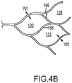
- device 100 is distinguishable from the various embodiments of device 10 described above in that the proximal-most cell structures 128 and 130 in the proximal end portion 114 include strut elements having a width dimension W1 larger than the width dimension W2 of the other strut elements within the expandable member 112.
- the proximal-most wall sections 160, 162 and 164 of cell structures 128 are made of struts having width W1.
- all the struts of the proximal-most cell structure 130 have an enhanced width W1.
- the inclusion and placement of the struts with width W1 provides several advantages.
- One advantage is that they permit the push force applied by the distal end of the elongate wire 140 to the proximal end 120 of elongate member 112 to be more evenly distributed about the circumference of the expandable member 112 as it is being advanced through the tortuous anatomy of a patient.
- the more evenly distributed push force minimizes the formation of localized high force components that would otherwise act on individual or multiple strut elements within the expandable member 112 to cause them to buckle.
- by including the struts of width W1 in the peripheral regions of proximal end portion 114 they greatly inhibit the tendency of the proximal end portion 114 to buckle under the push force applied to it by elongate wire 140.
- the as-cut width dimension W1 is about 0.0045 inches (0.114 mm) and the as-cut width dimension W2 is about 0.003 inches (0.076 mm)
- post-polishing of the device generally involves an etching process that typically results in a 40% to 50% reduction in the as-cut cross-sectional dimensions.
- width dimension W1 is shown as being the same among all struts having an enhanced width, this is not required.
- wall segments 158 may have an enhanced width dimension greater than the enhanced width dimension of wall segments 160, and wall segments 160 may have an enhanced width dimension greater than the enhanced width dimension of wall segments 162, and so on.
- the inner strut elements 166 of the proximal- most cell structure 130 may have an enhanced width dimension less than the enhanced width dimensions of struts 158.
- the radial thickness dimension of struts 158, 160, 162, 164, etc. may be enhanced in lieu of the width dimension or in combination thereof.
- some of the strut elements 180 in the distal end portion 118 of the expandable member 112 have a mass greater than that of the other struts to resist buckling and possible breaking of the struts as device 100 is advanced to a treatment site of a patient.
- struts 180 are dimensioned to have the same width as distal wire segment 150.
- the thickness dimension of struts 180 may be enhanced in lieu of the width dimension or in combination thereof.
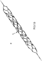
- Figures 6A and 6B illustrate a vascular treatment device 200 in accordance with another embodiment of the present invention.
- Figure 6A depicts device 200 in a two-dimensional plane view as if the device were cut and laid flat on a surface.
- Figure 6B depicts the device in its manufactured and/or expanded tubular configuration.
- Device 200 includes an expandable member 212 having a proximal end portion 214, a cylindrical main body portion 216 and a distal end portion 218 with an elongate flexible wire 240 attached to or otherwise coupled to the proximal end 220 of the expandable member.
- proximal wall segments 260 of cell structures 228 and 230 comprise linear or substantially linear strut elements as viewed in the two dimension plane view of Figure 6A .
- the linear strut elements 260 are aligned to form continuous and substantially linear rail segments 270 that extend from the proximal end 220 of proximal end portion 214 to a proximal-most end of main body portion 216 (again, as viewed in the two dimension plane view of Figure 6A ) and preferably are of the same length, but may be of different lengths.
- the resulting expandable member configuration is that as shown in Figure 6B .
- rail segments 270 are not in fact linear but are of a curved and non-undulating shape. This configuration advantageously provides rail segments 270 devoid of undulations thereby enhancing the rail segments' ability to distribute forces and resist buckling when a push force is applied to them.
- the angle ⁇ between the wire segment 240 and rail segments 270 ranges between about 140 degrees to about 150 degrees.
- one or both of the linear rail segments 270 have a width dimension W1 which is greater than the width dimension of the adjacent strut segments of cell structures 228 and 230.
- An enhanced width dimension W1 of one or both the linear rail segments 270 further enhances the rail segments' ability to distribute forces and resist buckling when a push force is applied to them.
- one or both of the linear rail segments 270 are provided with an enhanced thickness dimension, rather than an enhanced width dimension to achieve the same or similar result.
- both the width and thickness dimensions of one or both of the linear rail segments 270 are enhanced to achieve the same or similar results.
- the width and/or thickness dimensions of each of the rail segments 270 differ in a manner that causes a more even compression of the proximal end portion 214 of the expandable member 212 when it is loaded or retrieved into a delivery catheter or sheath (not shown).
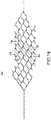
- Figures 7A and 7B illustrate a vascular treatment device 300 in accordance with another embodiment of the present invention.
- Figure 7A depicts device 300 in a two-dimensional plane view as if the device were cut and laid flat on a surface.
- Figure 7B depicts the device in its manufactured and/or expanded tubular configuration.
- Device 300 includes an expandable member 312 having a proximal end portion 314, a cylindrical main body portion 316 and a distal end portion 318 with an elongate flexible wire 340 attached to or otherwise coupled to the proximal end 320 of the expandable member.
- the construction of device 300 is similar to device 200 described above in conjunction with Figures 6A and 6B except that the proximal-most cell structure 330 comprises a substantially diamond shape as viewed in the two-dimensional plane of Figure 7A .
- the substantially diamond-shaped cell structure includes a pair of outer strut elements 358 and a pair of inner strut elements 360, each having an enhanced width and/or enhanced thickness dimension as previously discussed in conjunction with the embodiments of Figures 4 and 6 .
- the inner strut elements 360 intersect the outer strut elements 358 at an angle ⁇ between about 25.0 degrees to about 45.0 degrees as viewed in the two-dimensional plane view of Figure 7A .
- Maintaining the angular orientation between the inner and outer struts within in this range enhances the pushabilty of the expandable member 312 without the occurrence of buckling and without substantially affecting the expandable member's ability to assume a very small compressed diameter during delivery.
- the inner strut elements 360 have a mass less than that of the outer strut elements 358 that enables them to more easily bend as the expandable member 312 transitions from an expanded state to a compressed state. This assists in achieving a very small compressed diameter.
- the inner strut elements 360 are coupled to the outer strut elements 358 by curved elements 361 that enable the inner strut elements 360 to more easily flex when the expandable member 312 is compressed to its delivery position.
- Figure 8 illustrates an alternative embodiment of a vascular treatment device 400.
- Device 400 has a similar construction to that of device 200 depicted in Figures 6A and 6B with the exception that the expandable member 412 of device 400 is connected at its proximal end portion 414 with two distally extending elongate flexible wires 440 and 441.
- wire 440 is attached to or otherwise coupled to the proximal-most end 420 of proximal end portion 414
- wire 441 is attached to or otherwise coupled to the distal-most end 422 of the proximal end portion 414 at the junction with rail segment 470.
- an additional elongate flexible wire may be attached to the distal-most end 424.
- the use of two or more elongate flexible wires 440 and 441 to provide pushing forces to the proximal end portion 414 of elongate member 412 advantageously distributes the pushing force applied to the proximal end portion 414 to more than one attachment point.
- Figure 10 illustrates a two-dimensional plane view of a vascular treatment device 500 in another example that is not claimed.
- expandable member 512 includes a plurality of generally longitudinal undulating elements 524 with adjacent undulating elements being out-of-phase with one another and connected in a manner to form a plurality of diagonally disposed cell structures 526.
- the expandable member 512 includes a cylindrical portion 516 and a distal end portion 518 with the cell structures 526 in the main body portion 516 extending continuously and circumferentially around a longitudinal axis 530 of the expandable member 512.
- the cell structures 526 in the distal end portion 518 extend less than circumferentially around the longitudinal axis 530 of the expandable member 512.
- Attached to or otherwise coupled to each of the proximal-most cell structures 528 are proximally extending elongate flexible wires 540.
- the use of multiple elongate flexible wires 540 enables the pushing force applied to the proximal end of the expandable member 512 to be more evenly distributed about its proximal circumference.
- the proximal-most strut elements 528 have a width and/or thickness greater than the struts in the other portions of the expandable member 512. Such a feature further contributes to the push force being evenly distributed about the circumference of the expandable member 512 and also inhibits the strut elements directly receiving the push force from buckling.
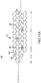
- Figures 11A and 11B illustrate a vascular treatment device 600 in accordance with another example that is not claimed.
- Figure 11A depicts device 600 in a two-dimensional plane view as if the device were cut and laid flat on a surface.
- Figure 11B depicts the device in its manufactured and/or expanded tubular configuration.
- expandable member 612 includes a plurality of generally longitudinal undulating elements 624 with adjacent undulating elements being interconnected by a plurality of curved connectors 628 to form a plurality of closed-cell structures 626 disposed about the length of the expandable member 612.
- the expandable member 612 includes a proximal end portion 614 and a cylindrical portion 616 with the cell structures 626 in the cylindrical portion 616 extending continuously and circumferentially around a longitudinal axis 630 of the expandable member 612.
- the cell structures 626 in the proximal end portion 614 extend less than circumferentially around the longitudinal axis 630 of the expandable member 612.
- the expandable member 612 includes a proximal end portion, a cylindrical main body portion and a distal end portion, much like the expandable member 12 depicted in Figures 1A and 1B .
- the cell structures 626 in the distal end portion of the expandable member would extend less than circumferentially around the longitudinal axis 630 of the expandable member 612 in a manner similar to the proximal end portion 614 shown in Figure HA.
- the expandable members of Figures 1A , 4A , 6A , 7A , 7C , 10 , 14 , 15 and 19-24 may be modified in a way so as to eliminate the distal end portion (e.g., distal end portion 18 in Figure 1A ) so that there exists only a proximal end portion and main body portion like that of Figure 11A .
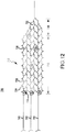
- Figure 12 illustrates a vascular treatment device 700 in accordance with another example that is not claimed.
- Figure 12 depicts device 700 in a two-dimensional plane view as if the device were cut and laid flat on a surface.
- expandable member 712 includes a plurality of generally longitudinal undulating elements 724 with adjacent undulating elements being interconnected by a plurality of curved connectors 728 to form a plurality of closed-cell structures 726 disposed about the length of the expandable member 712.
- the expandable member 712 includes a cylindrical portion 716 and a distal end portion 718 with the cell structures 726 in the cylindrical portion 716 extending continuously and circumferentially around a longitudinal axis 730 of the expandable member 712.
- the cell structures 726 in the distal end portion 718 extend less than circumferentially around the longitudinal axis 730 of the expandable member 712.
- attached to or otherwise coupled to each of the proximal-most cell structures 728 are proximally extending elongate flexible wires 740.
- This arrangement enables the pushing force applied to the proximal end of the expandable member 712 to be more evenly distributed about its proximal circumference.
- the proximal-most strut elements 730 have a width and/or thickness greater than the struts in the other portions of the expandable member 712. Such a feature further contributes to the push force being evenly distributed about the circumference of the expandable member 712 and also inhibits the strut elements directly receiving the push force from buckling.
- the expandable members of the present invention are advanced through the tortuous vascular anatomy of a patient to a treatment site, such as an embolic obstruction, in an unexpanded or compressed state of a first nominal diameter and are movable from the unexpanded state to a radially expanded state of a second nominal diameter greater than the first nominal diameter for deployment at the treatment site.
- a treatment site such as an embolic obstruction
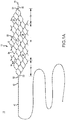
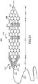
- FIGs 13A through 13C One manner of delivering and deploying expandable member 912 at the site of an embolic obstruction 950 is shown in Figures 13A through 13C .
- a delivery catheter 960 having an inner lumen 962 is advanced to the site of the embolic obstruction 950 so that its distal end 964 is positioned distal to the obstruction.
- the retrieval device 900 is placed into the delivery catheter by introducing the expandable member 912 into a proximal end of the delivery catheter (not shown) and then advancing the expandable member 912 through the lumen 962 of the delivery catheter by applying a pushing force to elongate flexible wire 940.
- the expandable member 912 is positioned at the distal end of the delivery catheter 960 as shown in Figure 13B so that the main body portion 916 is longitudinally aligned with the obstruction 950.
- Deployment of the expandable member 912 is achieved by proximally withdrawing the delivery catheter 960 while holding the expandable member 912 in a fixed position as shown in Figure 13C .
- the expandable member 912 is retracted, along with the delivery catheter 960, to a position outside the patient.
- the expandable member 912 is first partially retracted to engage with the distal end 964 of the delivery catheter 960 prior to fully retracting the devices from the patient.
- the expandable member 912 once the expandable member 912 is expanded at the obstruction 950, it is left to dwell there for a period of time in order to create a perfusion channel through the obstruction that causes the obstruction to be lysed by the resultant blood flow passing through the obstruction. In such an embodiment, it is not necessary that the expandable member 912 capture a portion of the obstruction 950 for retrieval outside the patient. When a sufficient portion of the obstruction 950 has been lysed to create a desired flow channel through the obstruction, or outright removal of the obstruction is achieved by the resultant blood flow, the expandable member 912 may be withdrawn into the delivery catheter 960 and subsequently removed from the patient.
- the expandable member 912 is expanded at the obstruction 950 and left to dwell there for a period of time in order to create a perfusion channel through the obstruction that causes the obstruction to be acted on by the resultant flow in a manner that makes the embolic obstruction more easily capturable by the expandable member and/or to make it more easily removable from the vessel wall of the patient.
- the blood flow created through the embolic obstruction may be made to flow through the obstruction for a period of time sufficient to change the morphology of the obstruction that makes it more easily captured by the expandable member and/or makes it more easily detachable from the vessel wall.
- the creation of blood flow across the obstruction 950 also acts to preserve tissue.
- the blood flow through the obstruction may be used to lyse the obstruction.
- lysing of the obstruction is performed for the purpose of preparing the obstruction to be more easily captured by the expandable member 912.
- the expandable member 912 is deployed from the distal end 964 of the delivery catheter 940 to cause it to engage with the obstruction. Removal of all, or a portion, of the obstruction 950 from the patient is then carried out in a manner similar to that described above.
- the expandable member 912 may be detached from the elongate wire 940 for permanent placement within the patient.
- the manner in which the elongate wire 940 is attached to the expandable member 912 allows the two components to be detached from one another. This may be achieved, for example, by the use of a mechanical interlock or an erodable electrolytic junction between the expandable member 912 and the elongate wire 940.
- the expandable members of the various embodiments may or may not include distal wire segments that are attached to their distal ends.
- vascular treatment devices that are configured to permanently place an expandable member at the site of an embolic obstruction do not include distal wire segments attached to the distal ends of the expandable members.
- One advantage associated with the expandable member cell patterns of the present invention is that withdrawing the expandable members by the application of a pulling force on the proximal elongate wire flexible wire urges the expandable members to assume a smaller expanded diameter while being withdrawn from the patient, thus decreasing the likelihood of injury to the vessel wall. Also, during clot retrieval as the profile of the expandable members decrease, the cell structures collapse and pinch down on the clot to increase clot retrieval efficacy. Another advantage is that the cell patterns permit the expandable members to be retracted into the lumen of the delivery catheter after they have been partially or fully deployed. As such, if at any given time it is determined that the expandable member has been partially or fully deployed at an improper location, it may be retracted into the distal end of the delivery catheter and repositioned to the correct location.
- a modified version of the vascular treatment device 200 of Figure 6A is shown that includes thin strut elements 280 intersecting at least some of the cell structures 226 located in the cylindrical main body portion 216 of expandable member 212.
- the thin strut elements 280 are dimensioned to have a width of less than the strut elements 282 that form the cell structures 226.
- strut elements 280 have an as-cut or polished width dimension that is between about 25% to about 50% smaller than the respective as-cut or polished width dimension of struts 262.
- a purpose of the thin struts 280 is to enhance the expandable member's ability to engage with and capture an embolic obstruction.
- the thinner width dimensions of the struts 280 make it easier for the struts to penetrate the obstruction.
- thin strut elements 280 is not limited to the embodiment of Figures 6 , but are applicable to all the various embodiments disclosed herein.
- multiple thin strut elements 280 are provided within one or more of the cell structures 226, and may also be used in conjunction with cell structures that have a single thin strut element and/or cell structures altogether devoid of thin strut elements.
- the density of the cell structures 226 is sufficient to effectively divert flow away from the aneurysm sack.
- intermediate strut elements similar to the strut elements 280 of Figures 14 and 15 are used to increase the effective wall surface of the expandable member.
- the intermediate strut elements may have the same, smaller, larger, or any combination thereof, dimensional characteristics of the cell structure struts.
- the size of the cell structures 226 is sufficient to facilitate passage of the coils through the cell structures.
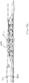
- Figure 16 illustrates a treatment device according to the embodiment of Figures 6A and 6B , wherein the pushability of the expandable member 212 during its advancement to the treatment site of a patient is enhanced by the inclusion of an internal wire segment 241 that extends between the proximal end 220 and distal end 222 of the expandable member 212.
- the internal wire segment may be a discrete element that is attached to the proximal and distal ends of the expandable member, or may preferably be a co-extension of the elongate flexible wire 240.
- the internal wire segment 241 assumes a substantially straight or linear configuration so as to adequately distribute at least a part of the pushing force to the distal end 222 of the expandable member.
- the expandable member 212 expands, it tends to foreshorten causing slack in the internal wire segment 241 that forms a long-pitched helix within the expandable member as shown in Figure 16 .
- An additional advantage associated with the use the internal wire segment 241 is that the formation of the internal helix upon expansion of the expandable member 212 assists in capturing the embolic obstruction.
- the pushability of the expandable member 212 during its advancement to the treatment site of a patient is enhanced by the inclusion of an external wire segment 243 that extend between the proximal end 220 and distal end 222 of the expandable member 212.
- the external wire segment may be discrete element that is attached to the proximal and distal ends of the expandable member, or may preferably be a co-extension of the elongate flexible wire 240.
- the external wire segment 243 assumes a substantially straight or linear configuration so as to adequately distribute at least a part of the pushing force to the distal end 222 of the expandable member.
- the expandable member 212 expands, it tends to foreshorten causing slack in the external wire segment 243 as shown in Figure 17 .
- An additional advantage associated with the use of the external wire segment 243 is that it directly acts on the obstruction while the expandable member 212 is expanded to assist in engaging and capturing the embolic obstruction.
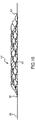
- a distal emboli capture device 251 is disposed on the distal wire segment 250, or otherwise attached to the distal end 222, of expandable member 212 as shown in Figure 18 .
- the function of the distal emboli capture device 251 is to capture emboli that may be dislodged from the embolic obstruction during the expansion of the expandable member 212 or during its removal from the patient to prevent distal embolization.
- the distal emboli capture device is shown as a coil. In alternative embodiments, baskets, embolic filters or other known emboli capture devices may be attached to the distal end 222 or distal wire segment 250 of expandable member 12.
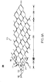
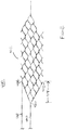
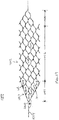
- Figure 19 illustrates a bodily duct or vascular treatment device 1000 in accordance with another embodiment of the present invention.
- Figure 19 depicts device 1000 in a two-dimensional plane view as if the device were cut and laid flat on a surface.
- Device 1000 includes an expandable member 1012 having a proximal end portion 1024, a cylindrical main body portion 1026 and a distal end portion 1028 with an elongate flexible wire 1014 attached to or otherwise coupled to the proximal end 1020 of the expandable member.
- the construction of device 1000 is similar to device 200 described above in conjunction with Figures 6A except that the cell structures 1018 and 1019 in the proximal end portion 1024 are more closely symmetrically arranged than the cell structures in the proximal end portion 214 of device 200.
- the more substantial symmetrical arrangement of the cell structures in the proximal end portion 1024 of device 1000 facilitates the loading or retrieval of the expandable member 1012 into a lumen of a delivery catheter or sheath (not shown) by causing the proximal end portion 1024 to collapse more evenly during compression.
- the proximal wall segments 1016 of cell structures 1018 and 1019 comprise linear or substantially linear strut elements as viewed in the two dimension plane view of Figure 19 .
- the linear strut elements 1016 are aligned to form continuous and substantially linear rail segments 1017 that extend from the proximal end 1020 of proximal end portion 1024 to a proximal-most end of main body portion 1026 (again, as viewed in the two dimension plane view of Figure 19 ) and preferably are of the same length.
- the angle ⁇ between the wire segment 1014 and rail segments 1017 ranges between about 140 degrees to about 150 degrees.
- one or both of the linear rail segments 1017 have a width dimension W1 which is greater than the width dimension of the adjacent strut segments of cell structures 1018 and/or 1019 and/or 1030.
- An enhanced width dimension W1 of one or both the linear rail segments 1017 further enhances the rail segments' ability to distribute forces and resist buckling when a push force is applied to them.
- one or both of the linear rail segments 1017 are provided with an enhanced thickness dimension, rather than an enhanced width dimension to achieve the same or similar result.
- both the width and thickness dimensions of one or both of the linear rail segments 1017 are enhanced to achieve the same or similar results.
- the width and/or thickness dimensions of each of the rail segments 1017 differ in a manner that causes a more even compression of the proximal end portion 1024 of the expandable member 1012 when it is collapsed as it is loaded or retrieved into a delivery catheter or sheath.
- the treatment device 1000 of Figure 19 is depicted having a longitudinal slit 1040 that extends from the proximal end 1020 to the distal end 1022 of the expandable member 1012.
- the slit 1040 permits the cell structures 1018, 1019 and 1030 to move relative to one another in a manner that inhibits the individual strut elements 1032 of the expandable member 1012 from buckling during compression of the expandable member 1012 as it is loaded or retrieved into a delivery catheter or sheath.
- slit 1040 extends less than the entire length of expandable member 1012 and is arranged to inhibit buckling of strategically important strut elements that most affect the expandable member's ability to be effectively loaded or withdrawn into a delivery catheter or sheath.
- slit 1040 is provided only in the proximal end portion 1024 of the expandable member 1012 where the likelihood of buckling or bending of struts 1032 is most likely to occur.
- slit 1040 is provided in both the proximal end portion 1024 and the cylindrical main body portion 1026 of expandable member 1012.
- Figure 21 illustrates the treatment device 1000 of Figure 19 having a diagonally disposed/spiral slit 1050 that extends the entire circumference of the expandable member 1012.
- the spiral slit 1050 originates at the distal position, or at a point adjacent to the distal position, of the proximal end portion 1024 of expandable member 1012.
- the spiral slit 1050 originates at the distal position 1021 of one of the linear rail segments 1017, or at a point distally adjacent to the distal position 1021, as shown in Figure 21 .
- slit 1050 extends diagonally along only a portion of the circumference of the cylindrical main body portion 1026 of the expandable member 1012.
- slit 1050 originates at the distal position 1021 of linear rail segment 1017.
- the originating point of the slit 1050 is located at the origination point of the bucking (absent the slit 1050) and extends in a longitudinal direction distally therefrom.
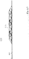
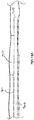
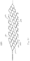
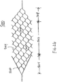
- Figure 23 illustrates a bodily duct or vascular treatment device 2000 in accordance with an embodiment of the present invention.
- Figure 23 depicts device 2000 in a two-dimensional plane view as if the device were cut and laid flat on a surface.
- Device 2000 includes a self-expandable member 2012 that is attached or otherwise coupled to an elongate flexible wire 2040 that extends proximally from the expandable member 2012.
- the expandable member 2012 is made of shape memory material, such as Nitinol, and is preferably laser cut from a tube.
- the expandable member 2012 has an integrally formed proximally extending wire segment 2042 that is used to join the elongate flexible wire 2040 to the expandable member 2012.
- flexible wire 2040 may be joined to wire segment 2042 by the use of solder, a weld, an adhesive, or other known attachment method.
- the distal end of flexible wire 2040 is attached directly to a proximal end 2020 of the expandable member 2012.
- expandable member 2012 includes a plurality of generally longitudinal undulating elements 2024 with adjacent undulating elements being coupled to one another in a manner to form a plurality of circumferentially-aligned cell structures 2026.
- the expandable member 2012 includes a proximal end portion 2013, a cylindrical main body portion 2014 and a distal end portion 2015 with the cell structures 2026 in the main body portion 2014 extending continuously and circumferentially around a longitudinal axis 2032 of the expandable member 2012.
- the cell structures in the proximal end portion 2013 and distal end portion 2015 extend less than circumferentially around the longitudinal axis 2032 of the expandable member 2012.
- the proximal wall segments 2016 of cell structures 2027, 2028, 2029 and 2030 comprise linear or substantially linear strut elements as viewed in the two dimension plane view of Figure 23 .
- the linear strut elements 2016 are aligned to form continuous and substantially linear rail segments 2017 that extend from the proximal end 2020 of proximal end portion 2013 to a proximal-most end of main body portion 2014 (again, as viewed in the two dimension plane view of Figure 23 ) and preferably are of the same length.
- rail segments 2017 are not in fact linear but are of a curved and non-undulating shape.
- This configuration advantageously provides rail segments 2017 devoid of undulations thereby enhancing the rail segments' ability to distribute forces and resist buckling when a push force is applied to them.
- the angle ⁇ between the wire segment 2042 or 2040, whichever the case may be, and rail segments 2017 ranges between about 140 degrees to about 150 degrees.
- the linear rail segments 2017 have a width dimension which is greater than the width dimension of the adjacent strut segments of cell structures 2027 and/or 2028 and/or 2029 and/or 2030 and/or 2026.
- An enhanced width of the linear rail segments 2017 further enhances the rail segments' ability to distribute forces and resist buckling when a push force is applied to the expandable member.
- the linear rail segments 2017 are provided with an enhanced thickness dimension, rather than an enhanced width dimension to achieve the same or similar result.
- both the width and thickness dimensions of the linear rail segments 2017 are enhanced to achieve the same or similar results.
- the width and/or thickness of the internal strut elements 2080 of proximal-most cell structure 2027 is also enhanced so as to resist buckling of these elements while the expandable member is being pushed through a sheath or delivery catheter.
- the "as-cut" nominal widths of the enhanced strut elements 2016 and 2080 are about 0.114 mm (0.0045 inches), while the "as-cut" nominal width of the other strut elements are about 0.076 mm (0.003 inches).
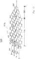
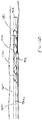
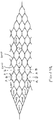
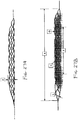
- Figures 24A and 24B illustrate a vascular treatment device 3000 of another embodiment of the present invention.
- Figure 24A depicts device 3000 in a two- dimensional plane view as if the device were cut and laid flat on a surface.
- Figure 24B depicts the device in its manufactured and/or expanded tubular configuration.
- the overall design of device 3000 is similar to the design of device 2000 depicted and described above in reference to Figure 23 .
- the primary difference between the two designs lays in the length "L" to width "W” ratio of the cell structures 2026, 2027, 2028, 2029 and 2030.
- the length to width ratios of the cells structures of Figure 24A are generally greater than the length to width ratios of the respective cell structures of Figure 23 .
- the lengths "L" of the cell structures of the device of Figure 24A in the "as-cut” configuration are generally greater than the lengths of the respective cell structures of Figure 23
- the widths "W” of the cell structures of the device of Figure 24A are generally smaller than the width of the respective cell structures of Figure 23 .
- the slope of the individual strut elements 2040 in the cell structures of Figure 24A are generally smaller than the slopes of the respective strut elements in the cell structures of Figure 23 .
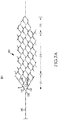
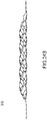
- Figures 26 , 27A and 27B illustrate an expandable member 5000 in another implementation.
- Expandable member 5000 includes a plurality of generally longitudinal undulating elements 5024 with adjacent undulating elements being out-of- phase with one another and connected in a manner to form a plurality of diagonally disposed cell structures 5026 angularly disposed between about 40.0 to about 50.0 degrees with respect to one another.
- the cell structures are diagonally displaced along about a 45.0 degree line.
- the expandable member 5000 includes a proximal end portion 5014, a cylindrical main body portion 5016 and a distal end portion 5018 with the cell structures 5026 in the main body portion 5016 extending continuously and circumferentially around a longitudinal axis of the expandable member 5000.
- the cell structures 5026 in the proximal end portion 5014 and distal end portion 5018 extend less than circumferentially around the longitudinal axis of the expandable member 5000.
- the expandable member has an unexpanded or crimped nominal diameter of about 1.0 millimeters and a designed maximum implantable diameter of about 4.0 millimeters.
- expandable member 5000 has an overall length dimension A of about 36.0 ⁇ 2.0 millimeters with the main body portion 5016 having a length P of about 19.0 ⁇ 2.0 millimeters.
- the strut width dimension N and thickness dimension O within the main body portion 5016 are about 0.053 mm ⁇ 0.01mm (0.0021 ⁇ 0.0004 inches) and about 0.081 ⁇ 0.013 mm (0.0032 ⁇ 0.0005 inches), respectively, while the strut width dimension L of the proximal rails 5030 is about 0.099 ⁇ 0.102 mm (0.0039 ⁇ 0.004 inches).
- expandable member 5000 is advanced through the tortuous vascular anatomy or bodily duct of a patient to a treatment site in an unexpanded or compressed state (not shown) of a first nominal diameter and is movable from the unexpanded state to a radially expanded state of a second nominal diameter greater than the first nominal diameter for deployment at the treatment site.
- first nominal diameter e.g., average diameter of main body portion 5016
- second nominal diameter e.g., average diameter of main body portion 5016 is between about 2.5 to about 5.0 millimeters.
- the dimensional and material characteristics of the cell structures 5026 residing in the main body portion 5016 of the expandable material 5000 are selected to produce sufficient radial force and contact interaction to cause the cell structures 5026 to engage with an embolic obstruction residing in the vascular in a manner that permits partial or full removal of the embolic obstruction from the patient.
- the dimensional and material characteristics of the cell structures 5026 in the main body portion 5016 are selected to produce a radial force per unit length of between about 0.005 N/mm to about 0.050 N/mm, preferable between about 0.010 N/mm to about 0.050 N/mm, and more preferably between about 0.030 N/mm and about 0.050 N/mm.
- the diameter of the main body portion 5016 in a designed fully expanded implanted state is about 4.0 millimeters with the cell pattern, strut dimensions and material being selected to produce a radial force of between about 0.030 N/mm to about 0.050 N/mm when the diameter of the main body portion is reduced to 1.5 millimeters.
- the cell pattern, strut dimensions and material(s) are selected to produce a radial force of between about 0.010 N/mm to about 0.020 N/mm when the diameter of the main body portion is reduced to 3.0 millimeters.
- the cell structures are constructed to have dimensional and material characteristics to create an overall radial force exerted along the length of the expandable member 5000 of between about 1.50N and about 2.50N when the expandable member 5000 is in the compressed or crimped state.
- About a -1.5N to a about a -3.5N overall reduction in radial force along the length of the expandable member per millimeter of expansion occurs during about an initial 0.50mm diametric range of expansion from the compressed or crimped state.
- the expandable member 5000 exerts a relatively high radial force during its initial expansion to enhance the likelihood that the struts of expandable member engage an obstruction within the duct of a patient upon initial deployment of the device.
- the rate at which the radial force diminishes is initially much greater during the initial expansion of the device than during subsequent expansion.
- the initial rate of reduction in the radial force during about the first 0.5mm of expansion is about 20.0 to 30.0 times greater than the rate of reduction during subsequent expansions.
- FIG. 29 Another advantage of the radial force characteristics depicted in Figure 29 is that during subsequent expansions, the rate of decrease in the over radial force along the length of the expandable member decreases in a linear-like fashion at a much reduced rate providing a level predictability of the radial force being exerted at the different expandable member diameters. Also, advantageously, the radial force exerted by the expandable member is designed to achieve a non-zero value when the expandable member is at a designed maximum implantable diameter.
- vascular treatment device of the embodiments disclosed herein is achievable with the use of a catheter, a sheath or any other device that is capable of carrying the device with the expandable member in a compressed state to the treatment site and which permits the subsequent deployment of the expandable member at a vascular treatment site.
- the vascular treatment site may be (1) at the neck of an aneurysm for diverting flow and/or facilitating the placement of coils or other like structures within the sack of an aneurysm, (2) at the site of an embolic obstruction with a purpose of removing the embolic obstruction, (3) at the site of a stenosis with a purpose of dilating the stenosis to increase blood flow through the vascular, etc..
Landscapes
- Health & Medical Sciences (AREA)
- Engineering & Computer Science (AREA)
- Biomedical Technology (AREA)
- General Health & Medical Sciences (AREA)
- Veterinary Medicine (AREA)
- Oral & Maxillofacial Surgery (AREA)
- Heart & Thoracic Surgery (AREA)
- Vascular Medicine (AREA)
- Life Sciences & Earth Sciences (AREA)
- Animal Behavior & Ethology (AREA)
- Cardiology (AREA)
- Public Health (AREA)
- Transplantation (AREA)
- Physics & Mathematics (AREA)
- Optics & Photonics (AREA)
- Gastroenterology & Hepatology (AREA)
- Pulmonology (AREA)
- Surgical Instruments (AREA)
- Media Introduction/Drainage Providing Device (AREA)
- Materials For Medical Uses (AREA)
- Prostheses (AREA)
Applications Claiming Priority (4)
| Application Number | Priority Date | Filing Date | Title |
|---|---|---|---|
| US12/499,713 US8795317B2 (en) | 2009-07-08 | 2009-07-08 | Embolic obstruction retrieval devices and methods |
| US12/573,676 US8795345B2 (en) | 2009-07-08 | 2009-10-05 | Vascular and bodily duct treatment devices and methods |
| US12/643,942 US20110009941A1 (en) | 2009-07-08 | 2009-12-21 | Vascular and bodily duct treatment devices and methods |
| PCT/US2010/041434 WO2011006013A1 (en) | 2009-07-08 | 2010-07-08 | Vascular and bodily duct treatment devices and methods |
Publications (3)
| Publication Number | Publication Date |
|---|---|
| EP2451378A1 EP2451378A1 (en) | 2012-05-16 |
| EP2451378A4 EP2451378A4 (en) | 2015-10-28 |
| EP2451378B1 true EP2451378B1 (en) | 2018-09-05 |
Family
ID=43428083
Family Applications (1)
| Application Number | Title | Priority Date | Filing Date |
|---|---|---|---|
| EP10797880.1A Active EP2451378B1 (en) | 2009-07-08 | 2010-07-08 | Vascular and bodily duct treatment devices |
Country Status (11)
| Country | Link |
|---|---|
| US (1) | US20110009941A1 (enExample) |
| EP (1) | EP2451378B1 (enExample) |
| JP (3) | JP5697825B2 (enExample) |
| KR (1) | KR101715967B1 (enExample) |
| CN (1) | CN102596098B (enExample) |
| AU (1) | AU2010271300C1 (enExample) |
| CA (1) | CA2767346A1 (enExample) |
| ES (1) | ES2692844T3 (enExample) |
| IL (1) | IL217357A0 (enExample) |
| RU (1) | RU2552308C2 (enExample) |
| WO (1) | WO2011006013A1 (enExample) |
Families Citing this family (102)
| Publication number | Priority date | Publication date | Assignee | Title |
|---|---|---|---|---|
| US8425549B2 (en) | 2002-07-23 | 2013-04-23 | Reverse Medical Corporation | Systems and methods for removing obstructive matter from body lumens and treating vascular defects |
| US8926680B2 (en) * | 2007-11-12 | 2015-01-06 | Covidien Lp | Aneurysm neck bridging processes with revascularization systems methods and products thereby |
| US11337714B2 (en) | 2007-10-17 | 2022-05-24 | Covidien Lp | Restoring blood flow and clot removal during acute ischemic stroke |
| US20100174309A1 (en) * | 2008-05-19 | 2010-07-08 | Mindframe, Inc. | Recanalization/revascularization and embolus addressing systems including expandable tip neuro-microcatheter |
| US9220522B2 (en) * | 2007-10-17 | 2015-12-29 | Covidien Lp | Embolus removal systems with baskets |
| US8088140B2 (en) | 2008-05-19 | 2012-01-03 | Mindframe, Inc. | Blood flow restorative and embolus removal methods |
| US10123803B2 (en) | 2007-10-17 | 2018-11-13 | Covidien Lp | Methods of managing neurovascular obstructions |
| US9198687B2 (en) * | 2007-10-17 | 2015-12-01 | Covidien Lp | Acute stroke revascularization/recanalization systems processes and products thereby |
| US8066757B2 (en) * | 2007-10-17 | 2011-11-29 | Mindframe, Inc. | Blood flow restoration and thrombus management methods |
| US8585713B2 (en) | 2007-10-17 | 2013-11-19 | Covidien Lp | Expandable tip assembly for thrombus management |
| EP2254485B1 (en) | 2008-02-22 | 2017-08-30 | Covidien LP | Apparatus for flow restoration |
| EP2271390A4 (en) | 2008-04-11 | 2016-07-20 | Covidien Lp | MONORAIL NEURO MICRO CATHETER FOR DISTRIBUTING MEDICAL DEVICES FOR THE TREATMENT OF STROKE, PROCESSES AND PRODUCTS |
| US10028747B2 (en) | 2008-05-01 | 2018-07-24 | Aneuclose Llc | Coils with a series of proximally-and-distally-connected loops for occluding a cerebral aneurysm |
| US10716573B2 (en) | 2008-05-01 | 2020-07-21 | Aneuclose | Janjua aneurysm net with a resilient neck-bridging portion for occluding a cerebral aneurysm |
| US9402707B2 (en) | 2008-07-22 | 2016-08-02 | Neuravi Limited | Clot capture systems and associated methods |
| US9005237B2 (en) | 2008-08-29 | 2015-04-14 | Rapid Medical Ltd. | Device and method for clot capture |
| US9034008B2 (en) | 2008-08-29 | 2015-05-19 | Rapid Medical Ltd. | Device and method involving stabilization during clot removal |
| US8758364B2 (en) | 2008-08-29 | 2014-06-24 | Rapid Medical Ltd. | Device and method for clot engagement and capture |
| US8529596B2 (en) | 2009-07-08 | 2013-09-10 | Concentric Medical, Inc. | Vascular and bodily duct treatment devices and methods |
| US9358140B1 (en) | 2009-11-18 | 2016-06-07 | Aneuclose Llc | Stent with outer member to embolize an aneurysm |
| EP2629684B1 (en) | 2010-10-22 | 2018-07-25 | Neuravi Limited | Clot engagement and removal system |
| WO2012064726A1 (en) * | 2010-11-12 | 2012-05-18 | Stryker Corporation | Axially variable radial pressure cages for clot capture |
| AU2012211992C1 (en) * | 2011-02-04 | 2016-07-21 | Concentric Medical, Inc. | Vascular and bodily duct treatment devices and methods |
| ES3029850T3 (en) | 2011-03-09 | 2025-06-25 | Neuravi Ltd | A clot retrieval device for removing occlusive clot from a blood vessel |
| US12076037B2 (en) | 2011-03-09 | 2024-09-03 | Neuravi Limited | Systems and methods to restore perfusion to a vessel |
| US11259824B2 (en) | 2011-03-09 | 2022-03-01 | Neuravi Limited | Clot retrieval device for removing occlusive clot from a blood vessel |
| DE102011014586B3 (de) * | 2011-03-21 | 2012-09-13 | Acandis Gmbh & Co. Kg | Medizinische Vorrichtung zur Behandlung von Körperhohlorganen, System mit einer derartigen Vorrichtung und Verfahren zur Herstellung einer derartigen Vorrichtung |
| US9028540B2 (en) * | 2011-03-25 | 2015-05-12 | Covidien Lp | Vascular stent with improved vessel wall apposition |
| ITMI20110796A1 (it) * | 2011-05-10 | 2012-11-11 | Fabrizio Farneti | Dispositivo medico impiantabile rimovibile in vasi sanguigni, particolarmente nell'aorta toracica con aneurisma. |
| BR112013028603A2 (pt) | 2011-05-11 | 2017-01-17 | Covidien Lp | dispositivo de remodelagem vascular |
| DE102011101522A1 (de) * | 2011-05-13 | 2012-11-15 | Phenox Gmbh | Thrombektomievorrichtung |
| US11026708B2 (en) | 2011-07-26 | 2021-06-08 | Thrombx Medical, Inc. | Intravascular thromboembolectomy device and method using the same |
| US9072620B2 (en) | 2011-11-04 | 2015-07-07 | Covidien Lp | Protuberant aneurysm bridging device deployment method |
| US8771341B2 (en) | 2011-11-04 | 2014-07-08 | Reverse Medical Corporation | Protuberant aneurysm bridging device and method of use |
| EP2790598B1 (en) * | 2011-12-16 | 2017-04-26 | Stryker Corporation | Embolectomy cage |
| ES2949175T3 (es) * | 2012-01-04 | 2023-09-26 | Rapid Medical Ltd | Dispositivos y métodos para ayudar a tratamientos médicos |
| CN102764170B (zh) * | 2012-07-18 | 2015-09-16 | 吕文峰 | 一种复合功能的血管内支架 |
| US9308007B2 (en) | 2012-08-14 | 2016-04-12 | W. L. Gore & Associates, Inc. | Devices and systems for thrombus treatment |
| US9254205B2 (en) | 2012-09-27 | 2016-02-09 | Covidien Lp | Vascular stent with improved vessel wall apposition |
| PT106709B (pt) | 2012-12-21 | 2015-06-09 | Inst Superior Tecnico | Emulsões aquosas reativas para revestimentos compósitos |
| US9439661B2 (en) * | 2013-01-09 | 2016-09-13 | Covidien Lp | Connection of a manipulation member, including a bend without substantial surface cracks, to an endovascular intervention device |
| CN104000635B (zh) * | 2013-02-21 | 2018-02-16 | 微创神通医疗科技(上海)有限公司 | 取栓器及取栓装置 |
| US9585741B2 (en) * | 2013-02-22 | 2017-03-07 | NeuroVasc Technologies, Inc | Embolus removal device with blood flow restriction and related methods |
| EP2958616B1 (en) * | 2013-02-22 | 2024-01-03 | NeuroVasc Technologies, Inc. | Blood flow restriction apparatus |
| US20160256255A9 (en) * | 2013-02-22 | 2016-09-08 | Jianlu Ma | Design and methods for a device with blood flow restriction feature for embolus removal in human vasculature |
| US20140277386A1 (en) | 2013-03-13 | 2014-09-18 | DePuy Synthes Products, LLC | Braided flow diverter using flat-round technology |
| EP3536252B1 (en) | 2013-03-14 | 2023-09-13 | Neuravi Limited | A clot retrieval device for removing occlusive clot from a blood vessel |
| US9433429B2 (en) | 2013-03-14 | 2016-09-06 | Neuravi Limited | Clot retrieval devices |
| TR201901830T4 (tr) | 2013-03-14 | 2019-03-21 | Neuravi Ltd | Kan damarlarından akut tıkanıkların giderilmesine yönelik cihazlar ve metotlar. |
| CN104068911A (zh) * | 2013-03-26 | 2014-10-01 | 上海微创医疗器械(集团)有限公司 | 血管取栓器及取栓装置 |
| US10383644B2 (en) * | 2013-10-17 | 2019-08-20 | Covidien Lp | Mechanical thrombectomy with proximal occlusion |
| JP2017506941A (ja) * | 2014-01-29 | 2017-03-16 | コンセントリック メディカル,インク. | 脈管・体内導管を治療するデバイスおよび方法 |
| CN106413593B (zh) | 2014-03-04 | 2019-10-15 | 莱克马克医学公司 | 具有多个凝块接合元件的血管内血栓栓子切除术装置 |
| US20170172722A1 (en) * | 2014-03-31 | 2017-06-22 | Spiration, Inc. D.B.A. Olympus Respiratory America | Anchoring mechanisms and systems for endoluminal devices |
| US9943628B2 (en) | 2014-07-30 | 2018-04-17 | Medtronic Vascular Inc. | Welded stent with radiopaque material localized at the welds and methods |
| HK1247066A1 (zh) * | 2014-11-26 | 2018-09-21 | Neuravi Limited | 从血管除去阻塞性血栓的取血栓装置 |
| US10617435B2 (en) | 2014-11-26 | 2020-04-14 | Neuravi Limited | Clot retrieval device for removing clot from a blood vessel |
| US11253278B2 (en) | 2014-11-26 | 2022-02-22 | Neuravi Limited | Clot retrieval system for removing occlusive clot from a blood vessel |
| EP3322357B8 (en) * | 2015-07-16 | 2020-01-15 | Perflow Medical Ltd. | Apparatus for vessel occlusion removal |
| EP3352689B1 (en) | 2015-09-21 | 2018-12-26 | Stryker Corporation | Embolectomy devices |
| US20170100143A1 (en) * | 2015-10-07 | 2017-04-13 | Stryker Corporation | Multiple barrel clot removal devices |
| KR101877486B1 (ko) * | 2015-12-09 | 2018-07-13 | 연세대학교 산학협력단 | 혈관 주행 경로 변경 장치 |
| CN105662534B (zh) * | 2016-01-06 | 2020-01-03 | 珠海通桥医疗科技有限公司 | 一种带有刺状结构的血管取栓装置及其血栓治疗仪 |
| CN105662532A (zh) * | 2016-01-06 | 2016-06-15 | 赵烜 | 一种带有半封闭结构的血管取栓装置及其血栓治疗仪 |
| CN105662533B (zh) * | 2016-01-06 | 2020-09-04 | 珠海通桥医疗科技有限公司 | 一种带有螺旋结构的血管取栓装置及其血栓治疗仪 |
| US10265089B2 (en) | 2016-02-12 | 2019-04-23 | Covidien Lp | Vascular device visibility |
| CA2957130C (en) * | 2016-02-12 | 2021-01-26 | Covidien Lp | Vascular device marker attachment |
| US10052185B2 (en) | 2016-02-12 | 2018-08-21 | Covidien Lp | Vascular device marker attachment |
| DE102016110199A1 (de) * | 2016-06-02 | 2017-12-07 | Phenox Gmbh | Vasospasmusbehandlung |
| CN109906058B (zh) | 2016-09-06 | 2022-06-07 | 尼尔拉维有限公司 | 用于从血管移除闭塞凝块的凝块取回装置 |
| CN106580397A (zh) * | 2016-12-20 | 2017-04-26 | 北京久事神康医疗科技有限公司 | 分段式取栓装置及利用该取栓装置取栓的方法 |
| CA3075398A1 (en) | 2017-09-11 | 2019-03-14 | Thrombx Medical, Inc. | Intravascular thromboembolectomy devices and methods |
| CN114587704B (zh) | 2017-09-12 | 2025-12-23 | W.L.戈尔及同仁股份有限公司 | 具有可旋转支柱的医疗装置基底 |
| US20250090185A1 (en) * | 2017-12-11 | 2025-03-20 | Covidien Lp | Electrically enhanced retrieval of material from vessel lumens |
| CN108042176A (zh) * | 2018-01-11 | 2018-05-18 | 恩脉(上海)医疗科技有限公司 | 取栓装置 |
| CN110090063B (zh) * | 2018-01-30 | 2022-07-08 | 上海沃比医疗科技有限公司 | 血栓捕捉装置及其方法 |
| US10179000B1 (en) | 2018-02-02 | 2019-01-15 | Highway 1 Medical, Inc. | Devices for retrieving an obstruction in a bodily duct of a patient |
| US20190274810A1 (en) * | 2018-03-12 | 2019-09-12 | Neurovasc Technologies, Inc. | Flow protection device for ischemic stroke treatment |
| CN108272488A (zh) * | 2018-04-09 | 2018-07-13 | 宋朝阳 | 一种动脉抓捕取栓支架及血栓取出装置 |
| CN109124837A (zh) * | 2018-07-06 | 2019-01-04 | 淮阴工学院 | 一种仿鱼鳞状的颅内取栓支架 |
| US10842498B2 (en) | 2018-09-13 | 2020-11-24 | Neuravi Limited | Systems and methods of restoring perfusion to a vessel |
| US11406416B2 (en) | 2018-10-02 | 2022-08-09 | Neuravi Limited | Joint assembly for vasculature obstruction capture device |
| CN109512486B (zh) * | 2018-11-12 | 2021-05-28 | 中国人民解放军总医院 | 分段式取栓支架 |
| US11712231B2 (en) | 2019-10-29 | 2023-08-01 | Neuravi Limited | Proximal locking assembly design for dual stent mechanical thrombectomy device |
| JP6989580B2 (ja) * | 2019-11-15 | 2022-01-05 | 株式会社Biomedical Solutions | ステント及びその検査方法 |
| US11517340B2 (en) | 2019-12-03 | 2022-12-06 | Neuravi Limited | Stentriever devices for removing an occlusive clot from a vessel and methods thereof |
| US11730501B2 (en) | 2020-04-17 | 2023-08-22 | Neuravi Limited | Floating clot retrieval device for removing clots from a blood vessel |
| US11717308B2 (en) | 2020-04-17 | 2023-08-08 | Neuravi Limited | Clot retrieval device for removing heterogeneous clots from a blood vessel |
| US11871946B2 (en) | 2020-04-17 | 2024-01-16 | Neuravi Limited | Clot retrieval device for removing clot from a blood vessel |
| JP7776876B2 (ja) * | 2020-06-05 | 2025-11-27 | グラビティ メディカル テクノロジー, インコーポレイテッド | 流動を回復させるための方法および装置 |
| US11737771B2 (en) | 2020-06-18 | 2023-08-29 | Neuravi Limited | Dual channel thrombectomy device |
| US11937836B2 (en) | 2020-06-22 | 2024-03-26 | Neuravi Limited | Clot retrieval system with expandable clot engaging framework |
| US11439418B2 (en) | 2020-06-23 | 2022-09-13 | Neuravi Limited | Clot retrieval device for removing clot from a blood vessel |
| US11395669B2 (en) | 2020-06-23 | 2022-07-26 | Neuravi Limited | Clot retrieval device with flexible collapsible frame |
| JP7669008B2 (ja) * | 2020-09-11 | 2025-04-28 | Jmr株式会社 | 弓部大動脈解離治療用ステント |
| US11864781B2 (en) | 2020-09-23 | 2024-01-09 | Neuravi Limited | Rotating frame thrombectomy device |
| US11937837B2 (en) | 2020-12-29 | 2024-03-26 | Neuravi Limited | Fibrin rich / soft clot mechanical thrombectomy device |
| US12029442B2 (en) | 2021-01-14 | 2024-07-09 | Neuravi Limited | Systems and methods for a dual elongated member clot retrieval apparatus |
| US12064130B2 (en) | 2021-03-18 | 2024-08-20 | Neuravi Limited | Vascular obstruction retrieval device having sliding cages pinch mechanism |
| JP7497518B2 (ja) * | 2021-03-23 | 2024-06-10 | 日本ライフライン株式会社 | ステント |
| US11974764B2 (en) | 2021-06-04 | 2024-05-07 | Neuravi Limited | Self-orienting rotating stentriever pinching cells |
| JP2023110722A (ja) * | 2022-01-28 | 2023-08-09 | ニプロ株式会社 | ステントリトリーバ |
Family Cites Families (94)
| Publication number | Priority date | Publication date | Assignee | Title |
|---|---|---|---|---|
| IT1126526B (it) * | 1979-12-07 | 1986-05-21 | Enrico Dormia | Estrattore chirurgico per asportare corpi estranei che si trovano nelle vie naturali del corpo umano,come calcoli e simili |
| US4706671A (en) * | 1985-05-02 | 1987-11-17 | Weinrib Harry P | Catheter with coiled tip |
| US4733665C2 (en) * | 1985-11-07 | 2002-01-29 | Expandable Grafts Partnership | Expandable intraluminal graft and method and apparatus for implanting an expandable intraluminal graft |
| US4886062A (en) * | 1987-10-19 | 1989-12-12 | Medtronic, Inc. | Intravascular radially expandable stent and method of implant |
| US5011488A (en) * | 1988-12-07 | 1991-04-30 | Robert Ginsburg | Thrombus extraction system |
| US5192286A (en) * | 1991-07-26 | 1993-03-09 | Regents Of The University Of California | Method and device for retrieving materials from body lumens |
| US5370683A (en) * | 1992-03-25 | 1994-12-06 | Cook Incorporated | Vascular stent |
| US5354308A (en) * | 1992-05-01 | 1994-10-11 | Beth Israel Hospital Association | Metal wire stent |
| US5496365A (en) * | 1992-07-02 | 1996-03-05 | Sgro; Jean-Claude | Autoexpandable vascular endoprosthesis |
| SE505436C2 (sv) * | 1993-04-27 | 1997-08-25 | Ams Medinvent Sa | Prostatastent |
| US5456667A (en) * | 1993-05-20 | 1995-10-10 | Advanced Cardiovascular Systems, Inc. | Temporary stenting catheter with one-piece expandable segment |
| US5370653A (en) * | 1993-07-22 | 1994-12-06 | Micro Therapeutics, Inc. | Thrombectomy method and apparatus |
| US5795331A (en) * | 1994-01-24 | 1998-08-18 | Micro Therapeutics, Inc. | Balloon catheter for occluding aneurysms of branch vessels |
| US5643312A (en) * | 1994-02-25 | 1997-07-01 | Fischell Robert | Stent having a multiplicity of closed circular structures |
| DE69502746T2 (de) * | 1994-02-25 | 1998-10-01 | David R Fischell | Stent mit einer Vielzahl geschlossener kreisförmiger Strukturen |
| US5843120A (en) * | 1994-03-17 | 1998-12-01 | Medinol Ltd. | Flexible-expandable stent |
| CA2189006A1 (en) * | 1994-04-29 | 1995-11-09 | Boston Scientific Corporation | Medical prosthetic stent and method of manufacture |
| EP0813397A4 (en) * | 1995-03-10 | 1999-10-06 | Cardiovascular Concepts Inc | TUBULAR ENDOLUMINAR PROSTHESIS WITH BEVELED ENDS |
| DK0734698T4 (da) * | 1995-04-01 | 2006-07-03 | Variomed Ag | Stent til transluminal implantation i hule organer |
| KR100325267B1 (ko) * | 1995-04-26 | 2003-10-11 | 메디놀 리미티드 | 관절성 스텐트 |
| US5681335A (en) * | 1995-07-31 | 1997-10-28 | Micro Therapeutics, Inc. | Miniaturized brush with hollow lumen brush body |
| US5895406A (en) * | 1996-01-26 | 1999-04-20 | Cordis Corporation | Axially flexible stent |
| US5895398A (en) * | 1996-02-02 | 1999-04-20 | The Regents Of The University Of California | Method of using a clot capture coil |
| US5843117A (en) * | 1996-02-14 | 1998-12-01 | Inflow Dynamics Inc. | Implantable vascular and endoluminal stents and process of fabricating the same |
| US5885258A (en) * | 1996-02-23 | 1999-03-23 | Memory Medical Systems, Inc. | Medical instrument with slotted memory metal tube |
| CA2192520A1 (en) * | 1996-03-05 | 1997-09-05 | Ian M. Penn | Expandable stent and method for delivery of same |
| US5968088A (en) * | 1996-03-07 | 1999-10-19 | William Cook, Europe A/S | Expandable stent |
| NZ331269A (en) * | 1996-04-10 | 2000-01-28 | Advanced Cardiovascular System | Expandable stent, its structural strength varying along its length |
| US6241760B1 (en) * | 1996-04-26 | 2001-06-05 | G. David Jang | Intravascular stent |
| US6066158A (en) * | 1996-07-25 | 2000-05-23 | Target Therapeutics, Inc. | Mechanical clot encasing and removal wire |
| US6206911B1 (en) * | 1996-12-19 | 2001-03-27 | Simcha Milo | Stent combination |
| SG161732A1 (en) * | 1997-01-24 | 2010-06-29 | Nexeon Medsystems Inc | Expandable device having bistable spring construction |
| US5827321A (en) * | 1997-02-07 | 1998-10-27 | Cornerstone Devices, Inc. | Non-Foreshortening intraluminal prosthesis |
| US5810872A (en) * | 1997-03-14 | 1998-09-22 | Kanesaka; Nozomu | Flexible stent |
| EP0916362B1 (en) * | 1997-03-31 | 2009-07-08 | Kabushikikaisha Igaki Iryo Sekkei | Stent for vessels |
| US5836966A (en) * | 1997-05-22 | 1998-11-17 | Scimed Life Systems, Inc. | Variable expansion force stent |
| US5913895A (en) * | 1997-06-02 | 1999-06-22 | Isostent, Inc. | Intravascular stent with enhanced rigidity strut members |
| US5800525A (en) * | 1997-06-04 | 1998-09-01 | Vascular Science, Inc. | Blood filter |
| EP0884029B1 (en) * | 1997-06-13 | 2004-12-22 | Gary J. Becker | Expandable intraluminal endoprosthesis |
| DE19834956B9 (de) * | 1997-08-01 | 2005-10-20 | Eckhard Alt | Stützprothese (Stent) |
| US5855600A (en) * | 1997-08-01 | 1999-01-05 | Inflow Dynamics Inc. | Flexible implantable stent with composite design |
| US6059822A (en) * | 1997-08-22 | 2000-05-09 | Uni-Cath Inc. | Stent with different mesh patterns |
| US5984929A (en) * | 1997-08-29 | 1999-11-16 | Target Therapeutics, Inc. | Fast detaching electronically isolated implant |
| US6066149A (en) * | 1997-09-30 | 2000-05-23 | Target Therapeutics, Inc. | Mechanical clot treatment device with distal filter |
| US6309414B1 (en) * | 1997-11-04 | 2001-10-30 | Sorin Biomedica Cardio S.P.A. | Angioplasty stents |
| US6482217B1 (en) * | 1998-04-10 | 2002-11-19 | Endicor Medical, Inc. | Neuro thrombectomy catheter |
| US6261319B1 (en) * | 1998-07-08 | 2001-07-17 | Scimed Life Systems, Inc. | Stent |
| US5911754A (en) * | 1998-07-24 | 1999-06-15 | Uni-Cath Inc. | Flexible stent with effective strut and connector patterns |
| US6042597A (en) * | 1998-10-23 | 2000-03-28 | Scimed Life Systems, Inc. | Helical stent design |
| US8092514B1 (en) * | 1998-11-16 | 2012-01-10 | Boston Scientific Scimed, Inc. | Stretchable anti-buckling coiled-sheet stent |
| CA2256131A1 (en) * | 1998-12-16 | 2000-06-16 | Micro Therapeutics, Inc. | Miniaturized medical brush |
| US6273910B1 (en) * | 1999-03-11 | 2001-08-14 | Advanced Cardiovascular Systems, Inc. | Stent with varying strut geometry |
| US6231589B1 (en) * | 1999-03-22 | 2001-05-15 | Microvena Corporation | Body vessel filter |
| US6350271B1 (en) * | 1999-05-17 | 2002-02-26 | Micrus Corporation | Clot retrieval device |
| US6458139B1 (en) * | 1999-06-21 | 2002-10-01 | Endovascular Technologies, Inc. | Filter/emboli extractor for use in variable sized blood vessels |
| US6409754B1 (en) * | 1999-07-02 | 2002-06-25 | Scimed Life Systems, Inc. | Flexible segmented stent |
| US20010047200A1 (en) * | 1999-10-13 | 2001-11-29 | Raymond Sun | Non-foreshortening intraluminal prosthesis |
| US6660021B1 (en) * | 1999-12-23 | 2003-12-09 | Advanced Cardiovascular Systems, Inc. | Intravascular device and system |
| AU2737001A (en) * | 1999-12-23 | 2001-07-03 | Percusurge, Inc. | Vascular filters with radiopaque markings |
| US6402771B1 (en) * | 1999-12-23 | 2002-06-11 | Guidant Endovascular Solutions | Snare |
| US6514273B1 (en) * | 2000-03-22 | 2003-02-04 | Endovascular Technologies, Inc. | Device for removal of thrombus through physiological adhesion |
| US6468301B1 (en) * | 2000-03-27 | 2002-10-22 | Aga Medical Corporation | Repositionable and recapturable vascular stent/graft |
| US20020049490A1 (en) * | 2000-04-11 | 2002-04-25 | Pollock David T. | Single-piece endoprosthesis with high expansion ratios |
| US6423091B1 (en) * | 2000-05-16 | 2002-07-23 | Cordis Corporation | Helical stent having flat ends |
| US6939362B2 (en) * | 2001-11-27 | 2005-09-06 | Advanced Cardiovascular Systems, Inc. | Offset proximal cage for embolic filtering devices |
| US6575995B1 (en) * | 2000-07-14 | 2003-06-10 | Advanced Cardiovascular Systems, Inc. | Expandable cage embolic material filter system and method |
| US6402431B1 (en) * | 2000-07-21 | 2002-06-11 | Edo Corporation, Fiber Science Division | Composite buoyancy module with foam core |
| AU2002233936A1 (en) * | 2000-11-07 | 2002-05-21 | Advanced Bio Prosthetic Surfaces, Ltd. | Endoluminal stent, self-fupporting endoluminal graft and methods of making same |
| US6679893B1 (en) * | 2000-11-16 | 2004-01-20 | Chestnut Medical Technologies, Inc. | Grasping device and method of use |
| WO2002054980A2 (en) * | 2001-01-16 | 2002-07-18 | Cordis Neurovascular, Inc. | Detachable self-expanding aneurysm cover device |
| US6818013B2 (en) * | 2001-06-14 | 2004-11-16 | Cordis Corporation | Intravascular stent device |
| US6673106B2 (en) * | 2001-06-14 | 2004-01-06 | Cordis Neurovascular, Inc. | Intravascular stent device |
| US7338510B2 (en) * | 2001-06-29 | 2008-03-04 | Advanced Cardiovascular Systems, Inc. | Variable thickness embolic filtering devices and method of manufacturing the same |
| US6551342B1 (en) * | 2001-08-24 | 2003-04-22 | Endovascular Technologies, Inc. | Embolic filter |
| US6818613B2 (en) * | 2001-11-07 | 2004-11-16 | Ortho-Mcneil Pharmaceutical, Inc. | Aqueous sustained-release formulations of proteins |
| US20030176914A1 (en) * | 2003-01-21 | 2003-09-18 | Rabkin Dmitry J. | Multi-segment modular stent and methods for manufacturing stents |
| US6641873B2 (en) * | 2001-12-21 | 2003-11-04 | Eastman Kodak Company | Method of forming a display using cholesteric material |
| US20040068314A1 (en) * | 2002-01-16 | 2004-04-08 | Jones Donald K. | Detachable self -expanding aneurysm cover device |
| JP2003272382A (ja) * | 2002-03-20 | 2003-09-26 | Mitsubishi Electric Corp | 半導体記憶装置 |
| US7195648B2 (en) * | 2002-05-16 | 2007-03-27 | Cordis Neurovascular, Inc. | Intravascular stent device |
| US7166120B2 (en) * | 2002-07-12 | 2007-01-23 | Ev3 Inc. | Catheter with occluding cuff |
| DE10233085B4 (de) * | 2002-07-19 | 2014-02-20 | Dendron Gmbh | Stent mit Führungsdraht |
| US7678119B2 (en) * | 2003-01-15 | 2010-03-16 | Scimed Life Systems, Inc. | Medical retrieval device with frangible basket |
| US20040199201A1 (en) * | 2003-04-02 | 2004-10-07 | Scimed Life Systems, Inc. | Embolectomy devices |
| US7651513B2 (en) * | 2003-04-03 | 2010-01-26 | Boston Scientific Scimed, Inc. | Flexible embolic device delivery system |
| US7331976B2 (en) * | 2003-04-29 | 2008-02-19 | Rex Medical, L.P. | Distal protection device |
| US8961583B2 (en) * | 2004-09-08 | 2015-02-24 | Cordis Corporation | Optimized flex link for expandable stent |
| WO2006053270A2 (en) * | 2004-11-10 | 2006-05-18 | Boston Scientific Limited | Atraumatic stent with reduced deployment force, method for making the same and method and apparatus for deploying and positioning the stent |
| ATE466557T1 (de) * | 2004-12-09 | 2010-05-15 | Med Inst Inc | Stent mit variabler krümmung |
| US7291166B2 (en) * | 2005-05-18 | 2007-11-06 | Advanced Cardiovascular Systems, Inc. | Polymeric stent patterns |
| US8109962B2 (en) * | 2005-06-20 | 2012-02-07 | Cook Medical Technologies Llc | Retrievable device having a reticulation portion with staggered struts |
| US20070288054A1 (en) * | 2006-06-13 | 2007-12-13 | Tanaka Don A | Vascular thrombectomby apparatus and method of use |
| RU2350301C1 (ru) * | 2007-06-28 | 2009-03-27 | Государственное научное учреждение Центральный научно-исследовательский и конструкторский институт робототехники и технической кибернетики (ГНУ ЦНИИ РТК) | Расправляемый внутрисосудистый стент |
| US8795317B2 (en) * | 2009-07-08 | 2014-08-05 | Concentric Medical, Inc. | Embolic obstruction retrieval devices and methods |
-
2009
- 2009-12-21 US US12/643,942 patent/US20110009941A1/en not_active Abandoned
-
2010
- 2010-07-08 JP JP2012519742A patent/JP5697825B2/ja active Active
- 2010-07-08 EP EP10797880.1A patent/EP2451378B1/en active Active
- 2010-07-08 CN CN201080030929.9A patent/CN102596098B/zh active Active
- 2010-07-08 AU AU2010271300A patent/AU2010271300C1/en active Active
- 2010-07-08 WO PCT/US2010/041434 patent/WO2011006013A1/en not_active Ceased
- 2010-07-08 RU RU2012104357/14A patent/RU2552308C2/ru not_active IP Right Cessation
- 2010-07-08 KR KR1020127003357A patent/KR101715967B1/ko active Active
- 2010-07-08 CA CA2767346A patent/CA2767346A1/en not_active Abandoned
- 2010-07-08 ES ES10797880.1T patent/ES2692844T3/es active Active
-
2012
- 2012-01-04 IL IL217357A patent/IL217357A0/en active IP Right Grant
-
2015
- 2015-02-11 JP JP2015024837A patent/JP6013694B2/ja active Active
-
2016
- 2016-09-22 JP JP2016184924A patent/JP6231175B2/ja active Active
Non-Patent Citations (1)
| Title |
|---|
| None * |
Also Published As
| Publication number | Publication date |
|---|---|
| RU2552308C2 (ru) | 2015-06-10 |
| IL217357A0 (en) | 2012-02-29 |
| ES2692844T3 (es) | 2018-12-05 |
| AU2010271300C1 (en) | 2015-01-22 |
| JP6013694B2 (ja) | 2016-10-25 |
| EP2451378A1 (en) | 2012-05-16 |
| AU2010271300A1 (en) | 2012-01-19 |
| AU2010271300B2 (en) | 2014-09-18 |
| EP2451378A4 (en) | 2015-10-28 |
| KR101715967B1 (ko) | 2017-03-13 |
| JP2017023779A (ja) | 2017-02-02 |
| JP5697825B2 (ja) | 2015-04-08 |
| WO2011006013A1 (en) | 2011-01-13 |
| JP2012532687A (ja) | 2012-12-20 |
| KR20120062702A (ko) | 2012-06-14 |
| CN102596098A (zh) | 2012-07-18 |
| JP6231175B2 (ja) | 2017-11-15 |
| US20110009941A1 (en) | 2011-01-13 |
| RU2012104357A (ru) | 2013-08-20 |
| CA2767346A1 (en) | 2011-01-13 |
| CN102596098B (zh) | 2018-04-20 |
| JP2015128611A (ja) | 2015-07-16 |
Similar Documents
| Publication | Publication Date | Title |
|---|---|---|
| EP2451378B1 (en) | Vascular and bodily duct treatment devices | |
| US8357178B2 (en) | Vascular and bodily duct treatment devices and methods | |
| US8357179B2 (en) | Vascular and bodily duct treatment devices and methods | |
| US8795345B2 (en) | Vascular and bodily duct treatment devices and methods | |
| US9044263B2 (en) | Vascular and bodily duct treatment devices and methods | |
| US8795317B2 (en) | Embolic obstruction retrieval devices and methods | |
| AU2012211992B2 (en) | Vascular and bodily duct treatment devices and methods | |
| EP3156004B1 (en) | Vascular and bodily duct treatment devices | |
| WO2015116690A1 (en) | Vascular and bodily duct treatment devices and methods | |
| JP2014511223A5 (enExample) |
Legal Events
| Date | Code | Title | Description |
|---|---|---|---|
| PUAI | Public reference made under article 153(3) epc to a published international application that has entered the european phase |
Free format text: ORIGINAL CODE: 0009012 |
|
| 17P | Request for examination filed |
Effective date: 20120208 |
|
| AK | Designated contracting states |
Kind code of ref document: A1 Designated state(s): AL AT BE BG CH CY CZ DE DK EE ES FI FR GB GR HR HU IE IS IT LI LT LU LV MC MK MT NL NO PL PT RO SE SI SK SM TR |
|
| DAX | Request for extension of the european patent (deleted) | ||
| RA4 | Supplementary search report drawn up and despatched (corrected) |
Effective date: 20150929 |
|
| STAA | Information on the status of an ep patent application or granted ep patent |
Free format text: STATUS: EXAMINATION IS IN PROGRESS |
|
| 17Q | First examination report despatched |
Effective date: 20161028 |
|
| RIN1 | Information on inventor provided before grant (corrected) |
Inventor name: WILSON, SCOTT D. Inventor name: BONSIGNORE, CRAIG L. Inventor name: SANDERS, ELLIOT H. Inventor name: GRANDFIELD, RYAN M. Inventor name: MILLER, JOHN H. Inventor name: PEDERSEN, KIRK L. Inventor name: VU, EMILY |
|
| RIN1 | Information on inventor provided before grant (corrected) |
Inventor name: MILLER, JOHN H. Inventor name: GRANDFIELD, RYAN M. Inventor name: WILSON, SCOTT D. Inventor name: BONSIGNORE, CRAIG L. Inventor name: VU, EMILY Inventor name: PEDERSEN, KIRK L. Inventor name: SANDERS, ELLIOT H. |
|
| REG | Reference to a national code |
Ref country code: DE Ref legal event code: R079 Ref document number: 602010053381 Country of ref document: DE Free format text: PREVIOUS MAIN CLASS: A61F0002060000 Ipc: A61F0002010000 |
|
| GRAP | Despatch of communication of intention to grant a patent |
Free format text: ORIGINAL CODE: EPIDOSNIGR1 |
|
| STAA | Information on the status of an ep patent application or granted ep patent |
Free format text: STATUS: GRANT OF PATENT IS INTENDED |
|
| RIC1 | Information provided on ipc code assigned before grant |
Ipc: A61F 2/01 20060101AFI20180301BHEP |
|
| INTG | Intention to grant announced |
Effective date: 20180327 |
|
| GRAS | Grant fee paid |
Free format text: ORIGINAL CODE: EPIDOSNIGR3 |
|
| GRAA | (expected) grant |
Free format text: ORIGINAL CODE: 0009210 |
|
| STAA | Information on the status of an ep patent application or granted ep patent |
Free format text: STATUS: THE PATENT HAS BEEN GRANTED |
|
| AK | Designated contracting states |
Kind code of ref document: B1 Designated state(s): AL AT BE BG CH CY CZ DE DK EE ES FI FR GB GR HR HU IE IS IT LI LT LU LV MC MK MT NL NO PL PT RO SE SI SK SM TR |
|
| REG | Reference to a national code |
Ref country code: GB Ref legal event code: FG4D |
|
| REG | Reference to a national code |
Ref country code: CH Ref legal event code: EP |
|
| REG | Reference to a national code |
Ref country code: AT Ref legal event code: REF Ref document number: 1036949 Country of ref document: AT Kind code of ref document: T Effective date: 20180915 |
|
| REG | Reference to a national code |
Ref country code: IE Ref legal event code: FG4D |
|
| REG | Reference to a national code |
Ref country code: DE Ref legal event code: R096 Ref document number: 602010053381 Country of ref document: DE |
|
| REG | Reference to a national code |
Ref country code: ES Ref legal event code: FG2A Ref document number: 2692844 Country of ref document: ES Kind code of ref document: T3 Effective date: 20181205 |
|
| REG | Reference to a national code |
Ref country code: NL Ref legal event code: FP |
|
| REG | Reference to a national code |
Ref country code: LT Ref legal event code: MG4D |
|
| PG25 | Lapsed in a contracting state [announced via postgrant information from national office to epo] |
Ref country code: FI Free format text: LAPSE BECAUSE OF FAILURE TO SUBMIT A TRANSLATION OF THE DESCRIPTION OR TO PAY THE FEE WITHIN THE PRESCRIBED TIME-LIMIT Effective date: 20180905 Ref country code: LT Free format text: LAPSE BECAUSE OF FAILURE TO SUBMIT A TRANSLATION OF THE DESCRIPTION OR TO PAY THE FEE WITHIN THE PRESCRIBED TIME-LIMIT Effective date: 20180905 Ref country code: GR Free format text: LAPSE BECAUSE OF FAILURE TO SUBMIT A TRANSLATION OF THE DESCRIPTION OR TO PAY THE FEE WITHIN THE PRESCRIBED TIME-LIMIT Effective date: 20181206 Ref country code: NO Free format text: LAPSE BECAUSE OF FAILURE TO SUBMIT A TRANSLATION OF THE DESCRIPTION OR TO PAY THE FEE WITHIN THE PRESCRIBED TIME-LIMIT Effective date: 20181205 Ref country code: SE Free format text: LAPSE BECAUSE OF FAILURE TO SUBMIT A TRANSLATION OF THE DESCRIPTION OR TO PAY THE FEE WITHIN THE PRESCRIBED TIME-LIMIT Effective date: 20180905 Ref country code: BG Free format text: LAPSE BECAUSE OF FAILURE TO SUBMIT A TRANSLATION OF THE DESCRIPTION OR TO PAY THE FEE WITHIN THE PRESCRIBED TIME-LIMIT Effective date: 20181205 |
|
| REG | Reference to a national code |
Ref country code: AT Ref legal event code: MK05 Ref document number: 1036949 Country of ref document: AT Kind code of ref document: T Effective date: 20180905 |
|
| PG25 | Lapsed in a contracting state [announced via postgrant information from national office to epo] |
Ref country code: HR Free format text: LAPSE BECAUSE OF FAILURE TO SUBMIT A TRANSLATION OF THE DESCRIPTION OR TO PAY THE FEE WITHIN THE PRESCRIBED TIME-LIMIT Effective date: 20180905 Ref country code: AL Free format text: LAPSE BECAUSE OF FAILURE TO SUBMIT A TRANSLATION OF THE DESCRIPTION OR TO PAY THE FEE WITHIN THE PRESCRIBED TIME-LIMIT Effective date: 20180905 Ref country code: LV Free format text: LAPSE BECAUSE OF FAILURE TO SUBMIT A TRANSLATION OF THE DESCRIPTION OR TO PAY THE FEE WITHIN THE PRESCRIBED TIME-LIMIT Effective date: 20180905 |
|
| PG25 | Lapsed in a contracting state [announced via postgrant information from national office to epo] |
Ref country code: RO Free format text: LAPSE BECAUSE OF FAILURE TO SUBMIT A TRANSLATION OF THE DESCRIPTION OR TO PAY THE FEE WITHIN THE PRESCRIBED TIME-LIMIT Effective date: 20180905 Ref country code: AT Free format text: LAPSE BECAUSE OF FAILURE TO SUBMIT A TRANSLATION OF THE DESCRIPTION OR TO PAY THE FEE WITHIN THE PRESCRIBED TIME-LIMIT Effective date: 20180905 Ref country code: CZ Free format text: LAPSE BECAUSE OF FAILURE TO SUBMIT A TRANSLATION OF THE DESCRIPTION OR TO PAY THE FEE WITHIN THE PRESCRIBED TIME-LIMIT Effective date: 20180905 Ref country code: EE Free format text: LAPSE BECAUSE OF FAILURE TO SUBMIT A TRANSLATION OF THE DESCRIPTION OR TO PAY THE FEE WITHIN THE PRESCRIBED TIME-LIMIT Effective date: 20180905 Ref country code: PL Free format text: LAPSE BECAUSE OF FAILURE TO SUBMIT A TRANSLATION OF THE DESCRIPTION OR TO PAY THE FEE WITHIN THE PRESCRIBED TIME-LIMIT Effective date: 20180905 Ref country code: IS Free format text: LAPSE BECAUSE OF FAILURE TO SUBMIT A TRANSLATION OF THE DESCRIPTION OR TO PAY THE FEE WITHIN THE PRESCRIBED TIME-LIMIT Effective date: 20190105 |
|
| PG25 | Lapsed in a contracting state [announced via postgrant information from national office to epo] |
Ref country code: PT Free format text: LAPSE BECAUSE OF FAILURE TO SUBMIT A TRANSLATION OF THE DESCRIPTION OR TO PAY THE FEE WITHIN THE PRESCRIBED TIME-LIMIT Effective date: 20190105 Ref country code: SK Free format text: LAPSE BECAUSE OF FAILURE TO SUBMIT A TRANSLATION OF THE DESCRIPTION OR TO PAY THE FEE WITHIN THE PRESCRIBED TIME-LIMIT Effective date: 20180905 Ref country code: SM Free format text: LAPSE BECAUSE OF FAILURE TO SUBMIT A TRANSLATION OF THE DESCRIPTION OR TO PAY THE FEE WITHIN THE PRESCRIBED TIME-LIMIT Effective date: 20180905 |
|
| REG | Reference to a national code |
Ref country code: DE Ref legal event code: R097 Ref document number: 602010053381 Country of ref document: DE |
|
| PLBE | No opposition filed within time limit |
Free format text: ORIGINAL CODE: 0009261 |
|
| STAA | Information on the status of an ep patent application or granted ep patent |
Free format text: STATUS: NO OPPOSITION FILED WITHIN TIME LIMIT |
|
| PG25 | Lapsed in a contracting state [announced via postgrant information from national office to epo] |
Ref country code: DK Free format text: LAPSE BECAUSE OF FAILURE TO SUBMIT A TRANSLATION OF THE DESCRIPTION OR TO PAY THE FEE WITHIN THE PRESCRIBED TIME-LIMIT Effective date: 20180905 |
|
| 26N | No opposition filed |
Effective date: 20190606 |
|
| PG25 | Lapsed in a contracting state [announced via postgrant information from national office to epo] |
Ref country code: SI Free format text: LAPSE BECAUSE OF FAILURE TO SUBMIT A TRANSLATION OF THE DESCRIPTION OR TO PAY THE FEE WITHIN THE PRESCRIBED TIME-LIMIT Effective date: 20180905 |
|
| REG | Reference to a national code |
Ref country code: NL Ref legal event code: PD Owner name: STRYKER CORPORATION; US Free format text: DETAILS ASSIGNMENT: CHANGE OF OWNER(S), ASSIGNMENT; FORMER OWNER NAME: CONCENTRIC MEDICAL, INC. Effective date: 20191119 |
|
| REG | Reference to a national code |
Ref country code: GB Ref legal event code: 732E Free format text: REGISTERED BETWEEN 20191230 AND 20191231 |
|
| REG | Reference to a national code |
Ref country code: DE Ref legal event code: R081 Ref document number: 602010053381 Country of ref document: DE Owner name: STRYKER CORP., KALAMAZOO, US Free format text: FORMER OWNER: CONCENTRIC MEDICAL, INC., MOUNTAIN VIEW, CALIF., US |
|
| REG | Reference to a national code |
Ref country code: ES Ref legal event code: PC2A Owner name: STRYKER CORPORATION Effective date: 20200129 |
|
| PG25 | Lapsed in a contracting state [announced via postgrant information from national office to epo] |
Ref country code: MC Free format text: LAPSE BECAUSE OF FAILURE TO SUBMIT A TRANSLATION OF THE DESCRIPTION OR TO PAY THE FEE WITHIN THE PRESCRIBED TIME-LIMIT Effective date: 20180905 |
|
| REG | Reference to a national code |
Ref country code: CH Ref legal event code: PL |
|
| REG | Reference to a national code |
Ref country code: ES Ref legal event code: PC2A Owner name: STRYKER CORPORATION Effective date: 20200320 |
|
| PG25 | Lapsed in a contracting state [announced via postgrant information from national office to epo] |
Ref country code: TR Free format text: LAPSE BECAUSE OF FAILURE TO SUBMIT A TRANSLATION OF THE DESCRIPTION OR TO PAY THE FEE WITHIN THE PRESCRIBED TIME-LIMIT Effective date: 20180905 |
|
| REG | Reference to a national code |
Ref country code: BE Ref legal event code: MM Effective date: 20190731 |
|
| PG25 | Lapsed in a contracting state [announced via postgrant information from national office to epo] |
Ref country code: LI Free format text: LAPSE BECAUSE OF NON-PAYMENT OF DUE FEES Effective date: 20190731 Ref country code: LU Free format text: LAPSE BECAUSE OF NON-PAYMENT OF DUE FEES Effective date: 20190708 Ref country code: BE Free format text: LAPSE BECAUSE OF NON-PAYMENT OF DUE FEES Effective date: 20190731 Ref country code: CH Free format text: LAPSE BECAUSE OF NON-PAYMENT OF DUE FEES Effective date: 20190731 |
|
| PG25 | Lapsed in a contracting state [announced via postgrant information from national office to epo] |
Ref country code: CY Free format text: LAPSE BECAUSE OF FAILURE TO SUBMIT A TRANSLATION OF THE DESCRIPTION OR TO PAY THE FEE WITHIN THE PRESCRIBED TIME-LIMIT Effective date: 20180905 |
|
| PG25 | Lapsed in a contracting state [announced via postgrant information from national office to epo] |
Ref country code: MT Free format text: LAPSE BECAUSE OF FAILURE TO SUBMIT A TRANSLATION OF THE DESCRIPTION OR TO PAY THE FEE WITHIN THE PRESCRIBED TIME-LIMIT Effective date: 20180905 Ref country code: HU Free format text: LAPSE BECAUSE OF FAILURE TO SUBMIT A TRANSLATION OF THE DESCRIPTION OR TO PAY THE FEE WITHIN THE PRESCRIBED TIME-LIMIT; INVALID AB INITIO Effective date: 20100708 |
|
| PG25 | Lapsed in a contracting state [announced via postgrant information from national office to epo] |
Ref country code: MK Free format text: LAPSE BECAUSE OF FAILURE TO SUBMIT A TRANSLATION OF THE DESCRIPTION OR TO PAY THE FEE WITHIN THE PRESCRIBED TIME-LIMIT Effective date: 20180905 |
|
| P01 | Opt-out of the competence of the unified patent court (upc) registered |
Effective date: 20230522 |
|
| PGFP | Annual fee paid to national office [announced via postgrant information from national office to epo] |
Ref country code: GB Payment date: 20250529 Year of fee payment: 16 |
|
| PGFP | Annual fee paid to national office [announced via postgrant information from national office to epo] |
Ref country code: NL Payment date: 20250613 Year of fee payment: 16 |
|
| PGFP | Annual fee paid to national office [announced via postgrant information from national office to epo] |
Ref country code: FR Payment date: 20250610 Year of fee payment: 16 |
|
| PGFP | Annual fee paid to national office [announced via postgrant information from national office to epo] |
Ref country code: IE Payment date: 20250610 Year of fee payment: 16 |
|
| PGFP | Annual fee paid to national office [announced via postgrant information from national office to epo] |
Ref country code: ES Payment date: 20250805 Year of fee payment: 16 |
|
| PGFP | Annual fee paid to national office [announced via postgrant information from national office to epo] |
Ref country code: DE Payment date: 20250604 Year of fee payment: 16 |
|
| PGFP | Annual fee paid to national office [announced via postgrant information from national office to epo] |
Ref country code: IT Payment date: 20250623 Year of fee payment: 16 |