EP2444985B1 - Production method of rare earth magnet - Google Patents
Production method of rare earth magnet Download PDFInfo
- Publication number
- EP2444985B1 EP2444985B1 EP10306166.9A EP10306166A EP2444985B1 EP 2444985 B1 EP2444985 B1 EP 2444985B1 EP 10306166 A EP10306166 A EP 10306166A EP 2444985 B1 EP2444985 B1 EP 2444985B1
- Authority
- EP
- European Patent Office
- Prior art keywords
- heat treatment
- rare earth
- temperature
- grain boundary
- earth magnet
- Prior art date
- Legal status (The legal status is an assumption and is not a legal conclusion. Google has not performed a legal analysis and makes no representation as to the accuracy of the status listed.)
- Active
Links
Images


Classifications
-
- H—ELECTRICITY
- H01—ELECTRIC ELEMENTS
- H01F—MAGNETS; INDUCTANCES; TRANSFORMERS; SELECTION OF MATERIALS FOR THEIR MAGNETIC PROPERTIES
- H01F41/00—Apparatus or processes specially adapted for manufacturing or assembling magnets, inductances or transformers; Apparatus or processes specially adapted for manufacturing materials characterised by their magnetic properties
- H01F41/02—Apparatus or processes specially adapted for manufacturing or assembling magnets, inductances or transformers; Apparatus or processes specially adapted for manufacturing materials characterised by their magnetic properties for manufacturing cores, coils, or magnets
- H01F41/0253—Apparatus or processes specially adapted for manufacturing or assembling magnets, inductances or transformers; Apparatus or processes specially adapted for manufacturing materials characterised by their magnetic properties for manufacturing cores, coils, or magnets for manufacturing permanent magnets
- H01F41/0273—Imparting anisotropy
-
- C—CHEMISTRY; METALLURGY
- C22—METALLURGY; FERROUS OR NON-FERROUS ALLOYS; TREATMENT OF ALLOYS OR NON-FERROUS METALS
- C22C—ALLOYS
- C22C38/00—Ferrous alloys, e.g. steel alloys
- C22C38/002—Ferrous alloys, e.g. steel alloys containing In, Mg, or other elements not provided for in one single group C22C38/001 - C22C38/60
-
- C—CHEMISTRY; METALLURGY
- C22—METALLURGY; FERROUS OR NON-FERROUS ALLOYS; TREATMENT OF ALLOYS OR NON-FERROUS METALS
- C22C—ALLOYS
- C22C38/00—Ferrous alloys, e.g. steel alloys
- C22C38/005—Ferrous alloys, e.g. steel alloys containing rare earths, i.e. Sc, Y, Lanthanides
-
- C—CHEMISTRY; METALLURGY
- C22—METALLURGY; FERROUS OR NON-FERROUS ALLOYS; TREATMENT OF ALLOYS OR NON-FERROUS METALS
- C22C—ALLOYS
- C22C38/00—Ferrous alloys, e.g. steel alloys
- C22C38/06—Ferrous alloys, e.g. steel alloys containing aluminium
-
- C—CHEMISTRY; METALLURGY
- C22—METALLURGY; FERROUS OR NON-FERROUS ALLOYS; TREATMENT OF ALLOYS OR NON-FERROUS METALS
- C22C—ALLOYS
- C22C38/00—Ferrous alloys, e.g. steel alloys
- C22C38/16—Ferrous alloys, e.g. steel alloys containing copper
-
- H—ELECTRICITY
- H01—ELECTRIC ELEMENTS
- H01F—MAGNETS; INDUCTANCES; TRANSFORMERS; SELECTION OF MATERIALS FOR THEIR MAGNETIC PROPERTIES
- H01F1/00—Magnets or magnetic bodies characterised by the magnetic materials therefor; Selection of materials for their magnetic properties
- H01F1/01—Magnets or magnetic bodies characterised by the magnetic materials therefor; Selection of materials for their magnetic properties of inorganic materials
-
- H—ELECTRICITY
- H01—ELECTRIC ELEMENTS
- H01F—MAGNETS; INDUCTANCES; TRANSFORMERS; SELECTION OF MATERIALS FOR THEIR MAGNETIC PROPERTIES
- H01F41/00—Apparatus or processes specially adapted for manufacturing or assembling magnets, inductances or transformers; Apparatus or processes specially adapted for manufacturing materials characterised by their magnetic properties
- H01F41/005—Impregnating or encapsulating
-
- H—ELECTRICITY
- H01—ELECTRIC ELEMENTS
- H01F—MAGNETS; INDUCTANCES; TRANSFORMERS; SELECTION OF MATERIALS FOR THEIR MAGNETIC PROPERTIES
- H01F41/00—Apparatus or processes specially adapted for manufacturing or assembling magnets, inductances or transformers; Apparatus or processes specially adapted for manufacturing materials characterised by their magnetic properties
- H01F41/32—Apparatus or processes specially adapted for manufacturing or assembling magnets, inductances or transformers; Apparatus or processes specially adapted for manufacturing materials characterised by their magnetic properties for applying conductive, insulating or magnetic material on a magnetic film, specially adapted for a thin magnetic film
-
- B—PERFORMING OPERATIONS; TRANSPORTING
- B22—CASTING; POWDER METALLURGY
- B22F—WORKING METALLIC POWDER; MANUFACTURE OF ARTICLES FROM METALLIC POWDER; MAKING METALLIC POWDER; APPARATUS OR DEVICES SPECIALLY ADAPTED FOR METALLIC POWDER
- B22F3/00—Manufacture of workpieces or articles from metallic powder characterised by the manner of compacting or sintering; Apparatus specially adapted therefor ; Presses and furnaces
- B22F3/24—After-treatment of workpieces or articles
- B22F2003/248—Thermal after-treatment
-
- B—PERFORMING OPERATIONS; TRANSPORTING
- B22—CASTING; POWDER METALLURGY
- B22F—WORKING METALLIC POWDER; MANUFACTURE OF ARTICLES FROM METALLIC POWDER; MAKING METALLIC POWDER; APPARATUS OR DEVICES SPECIALLY ADAPTED FOR METALLIC POWDER
- B22F2998/00—Supplementary information concerning processes or compositions relating to powder metallurgy
- B22F2998/10—Processes characterised by the sequence of their steps
-
- B—PERFORMING OPERATIONS; TRANSPORTING
- B22—CASTING; POWDER METALLURGY
- B22F—WORKING METALLIC POWDER; MANUFACTURE OF ARTICLES FROM METALLIC POWDER; MAKING METALLIC POWDER; APPARATUS OR DEVICES SPECIALLY ADAPTED FOR METALLIC POWDER
- B22F2999/00—Aspects linked to processes or compositions used in powder metallurgy
-
- C—CHEMISTRY; METALLURGY
- C22—METALLURGY; FERROUS OR NON-FERROUS ALLOYS; TREATMENT OF ALLOYS OR NON-FERROUS METALS
- C22C—ALLOYS
- C22C2202/00—Physical properties
- C22C2202/02—Magnetic
-
- H—ELECTRICITY
- H01—ELECTRIC ELEMENTS
- H01F—MAGNETS; INDUCTANCES; TRANSFORMERS; SELECTION OF MATERIALS FOR THEIR MAGNETIC PROPERTIES
- H01F1/00—Magnets or magnetic bodies characterised by the magnetic materials therefor; Selection of materials for their magnetic properties
- H01F1/01—Magnets or magnetic bodies characterised by the magnetic materials therefor; Selection of materials for their magnetic properties of inorganic materials
- H01F1/03—Magnets or magnetic bodies characterised by the magnetic materials therefor; Selection of materials for their magnetic properties of inorganic materials characterised by their coercivity
- H01F1/032—Magnets or magnetic bodies characterised by the magnetic materials therefor; Selection of materials for their magnetic properties of inorganic materials characterised by their coercivity of hard-magnetic materials
- H01F1/04—Magnets or magnetic bodies characterised by the magnetic materials therefor; Selection of materials for their magnetic properties of inorganic materials characterised by their coercivity of hard-magnetic materials metals or alloys
- H01F1/047—Alloys characterised by their composition
- H01F1/053—Alloys characterised by their composition containing rare earth metals
- H01F1/055—Alloys characterised by their composition containing rare earth metals and magnetic transition metals, e.g. SmCo5
- H01F1/057—Alloys characterised by their composition containing rare earth metals and magnetic transition metals, e.g. SmCo5 and IIIa elements, e.g. Nd2Fe14B
- H01F1/0571—Alloys characterised by their composition containing rare earth metals and magnetic transition metals, e.g. SmCo5 and IIIa elements, e.g. Nd2Fe14B in the form of particles, e.g. rapid quenched powders or ribbon flakes
- H01F1/0575—Alloys characterised by their composition containing rare earth metals and magnetic transition metals, e.g. SmCo5 and IIIa elements, e.g. Nd2Fe14B in the form of particles, e.g. rapid quenched powders or ribbon flakes pressed, sintered or bonded together
- H01F1/0576—Alloys characterised by their composition containing rare earth metals and magnetic transition metals, e.g. SmCo5 and IIIa elements, e.g. Nd2Fe14B in the form of particles, e.g. rapid quenched powders or ribbon flakes pressed, sintered or bonded together pressed, e.g. hot working
-
- H—ELECTRICITY
- H01—ELECTRIC ELEMENTS
- H01F—MAGNETS; INDUCTANCES; TRANSFORMERS; SELECTION OF MATERIALS FOR THEIR MAGNETIC PROPERTIES
- H01F1/00—Magnets or magnetic bodies characterised by the magnetic materials therefor; Selection of materials for their magnetic properties
- H01F1/01—Magnets or magnetic bodies characterised by the magnetic materials therefor; Selection of materials for their magnetic properties of inorganic materials
- H01F1/03—Magnets or magnetic bodies characterised by the magnetic materials therefor; Selection of materials for their magnetic properties of inorganic materials characterised by their coercivity
- H01F1/032—Magnets or magnetic bodies characterised by the magnetic materials therefor; Selection of materials for their magnetic properties of inorganic materials characterised by their coercivity of hard-magnetic materials
- H01F1/04—Magnets or magnetic bodies characterised by the magnetic materials therefor; Selection of materials for their magnetic properties of inorganic materials characterised by their coercivity of hard-magnetic materials metals or alloys
- H01F1/047—Alloys characterised by their composition
- H01F1/053—Alloys characterised by their composition containing rare earth metals
- H01F1/055—Alloys characterised by their composition containing rare earth metals and magnetic transition metals, e.g. SmCo5
- H01F1/057—Alloys characterised by their composition containing rare earth metals and magnetic transition metals, e.g. SmCo5 and IIIa elements, e.g. Nd2Fe14B
- H01F1/0571—Alloys characterised by their composition containing rare earth metals and magnetic transition metals, e.g. SmCo5 and IIIa elements, e.g. Nd2Fe14B in the form of particles, e.g. rapid quenched powders or ribbon flakes
- H01F1/0575—Alloys characterised by their composition containing rare earth metals and magnetic transition metals, e.g. SmCo5 and IIIa elements, e.g. Nd2Fe14B in the form of particles, e.g. rapid quenched powders or ribbon flakes pressed, sintered or bonded together
- H01F1/0577—Alloys characterised by their composition containing rare earth metals and magnetic transition metals, e.g. SmCo5 and IIIa elements, e.g. Nd2Fe14B in the form of particles, e.g. rapid quenched powders or ribbon flakes pressed, sintered or bonded together sintered
-
- H—ELECTRICITY
- H01—ELECTRIC ELEMENTS
- H01F—MAGNETS; INDUCTANCES; TRANSFORMERS; SELECTION OF MATERIALS FOR THEIR MAGNETIC PROPERTIES
- H01F10/00—Thin magnetic films, e.g. of one-domain structure
- H01F10/08—Thin magnetic films, e.g. of one-domain structure characterised by magnetic layers
- H01F10/10—Thin magnetic films, e.g. of one-domain structure characterised by magnetic layers characterised by the composition
- H01F10/12—Thin magnetic films, e.g. of one-domain structure characterised by magnetic layers characterised by the composition being metals or alloys
- H01F10/126—Thin magnetic films, e.g. of one-domain structure characterised by magnetic layers characterised by the composition being metals or alloys containing rare earth metals
Definitions
- the present invention relates to a production method of a rare earth magnet, which is usually represented by a neodymium magnet. More specifically, the present invention relates to a production method of a rare earth magnet having a structure composed of nano-size crystal grains.
- a rare earth magnet which is represented by a neodymium magnet (Nd 2 Fe 14 B), is used as a very strong permanent magnet having a high magnetic flux density for various applications.
- the crystal grain size is being reduced to the nano-scale (several tens to several hundreds of nm).
- a heat treatment is applied after sintering so as to increase the magnetic coercive force.
- a heat treatment is applied after sintering so as to increase the magnetic coercive force.
- Patent Documents 1 and 2 it is confirmed that the magnetic coercive force can be enhanced, when an aging heat treatment at a temperature of not more than the sintering temperature is applied.
- the enhancement of the magnetic coercive force by a heat treatment is desirable. Accordingly, it is needed to establish an optimal heat treatment method.
- An object of the present invention is to provide a production method of a rare earth magnet, which is usually represented by a neodymium magnet (Nd 2 Fe 14 B), wherein a heat treatment method capable of enhancing the magnetic characteristics, particularly the magnetic coercive force is used.
- a rare earth magnet which is usually represented by a neodymium magnet (Nd 2 Fe 14 B)
- a heat treatment method capable of enhancing the magnetic characteristics, particularly the magnetic coercive force is used.
- the present invention provides a method for producing a rare earth magnet, comprising: applying a heat treatment with pressurization to an article having a rare earth magnet composition at a temperature sufficiently high to enable diffusion or fluidization of a grain boundary phase and, at the same
- the orientation treatment is a hot working.
- a heat treatment is applied with pressurization at a temperature sufficiently high to enable diffusion or fluidization of a grain boundary phase and, at the same time, low enough to prevent coarsening of the crystal grain size.
- a grain boundary phase unevenly distributed in the space formed among crystal grains and at triple points, that is, at a portion where three or more crystal grains are joined, is re-distributed to the entire grain boundary in order to create the state wherein a nano-size main phase crystal grain is covered with a grain boundary phase to prevent the exchange coupling between main phase grains and thereby to enhance the magnetic coercive force.
- the magnetic coercive force can be enhanced, while preventing coarsening of the structure due to heat treatment.
- the heat treatment is applied to a rare earth magnet which has a rare earth magnet composition configured to have a nanocrystalline structure, and has been subjected to an orientation treatment.
- the amount v of R 1 (one or more kinds of rare earth elements including Y) is 13 ⁇ v ⁇ 17 and the amount y of B is 5 ⁇ y ⁇ 16.
- rare earth magnet composition is indicated by the following compositional formula, and composed of a main phase ((R 2 R 3 ) 2 (FeCo) 14 B) and grain boundary phases ((R 2 R 3 )(FeCo) 4 B 4 phase and R 2 R 3 phase): R 2 a R 3 b Fe c Co d B e M 2 f
- a molten metal having a rare earth magnet composition is quenched to form flakes having a structure composed of nanocrystals (nanocrystalline structure).
- the nanocrystalline structure is a polycrystalline structure where the crystal grain is of nano size.
- the nano size is a size in the range 10 to 300 nm.
- the quenching rate is in the range suitable for allowing the solidified structure to become a nanocrystalline structure. If the quenching rate is less than this range, the solidified structure becomes a coarse crystal structure, and thereby a nanocrystalline structure is not obtained. If the quenching rate is more than this range, the solidified structure is amorphous, and thereby a nanocrystalline structure is not obtained.
- the method for quenching solidification need not be particularly limited, but this is preferably performed by using a single-roll furnace shown in Fig. 1 .
- a molten alloy is ejected out from a nozzle (3) on the outer circumferential surface of a single roll (2) rotating in the direction of the arrow (1), the molten alloy is quenched and solidified, and thereby becomes flakes (4).
- quenched flakes are formed by solidification due to one-direction solidification from the roll's outer circumferential surface with which the flake is in contact, out towards the free (outer) surface of the flake, and therefore a low melting-point phase is formed on the free surface of a flake (last solidified part).
- the presence of a low melting-point phase on the flake surface is very advantageous for low-temperature sintering, because a sintering reaction occurs at a low temperature in the sintering step.
- a twin roll method because solidification occurs from both surfaces of a flake towards the center part of the flake, a low melting point phase is formed not on the surface but in the center part of the flake. Therefore, in this case, a low-temperature sintering effect between flakes is not obtained.
- quenched flakes have either a nanocrystalline structure or an amorphous structure.
- quenched flakes of nanocrystalline structure needs to be selected from the mixture of the quenched flakes having different structures.
- the quenched flakes are separated into crystalline flakes and amorphous flakes by using a low magnetization magnet. More specifically, out of a collection of quenched flakes (1), amorphous quenched flakes are magnetized by the magnet and kept from falling (2), whereas crystalline quenched flakes are not magnetized by the magnet and are allowed to fall (3).
- the produced (if desired, separated) quenched flakes of nanocrystalline structure are sintered.
- the sintering need not be particularly limited in its method, but must be performed at a low temperature in as short a time as possible so as to prevent coarsening of the nanocrystalline structure. Accordingly, it is necessary to perform the sintering under pressure. By performing the sintering under pressure, the sintering reaction is accelerated and thereby low-temperature sintering becomes possible, so that the nanocrystal structure can be maintained.
- the heating rate to the sintering temperature is also preferably high.
- SPS Spark Plasma Sintering
- sintering need not be limited to SPS sintering, and may also be performed by using a hot press.
- thermoforming machine As a type of hot press, it is also possible to use a normal press molding machine or the like in combination with high frequency heating and heating with an attached heater.
- high frequency heating the work piece is directly heated by using an insulating die/punch tool, or the work piece is indirectly heated by the heated die/punch after heating the dye/punch by using an electrically conductive die/punch tool.
- heating with an attached heater the die/punch tool is heated with a cartridge heater, a band heater or the like.
- the obtained sintered body is subjected to an orientation treatment.
- a representative method for the orientation treatment is a hot working.
- severe plastic deformation where the working degree, i.e., the decrease in thickness of the sintered body, is 30% or more, 40% or more, 50% or more, or 60% or more, is preferred.
- the crystal grain itself and/or the crystal direction in the crystal grain are rotated in association with slide deformation, and thereby the sintered body is oriented (development of texture) in the easy direction of magnetization in the case of a hexagonal or _tetragonal crystal, the c axis direction).
- the sintered body has a nanocrystalline structure
- the crystal grain itself and/or the crystal direction in the crystal grain are easily rotated and thereby the orientation is accelerated.
- a fine aggregate structure having highly-oriented nano-size crystal grains is achieved, and an anisotropic rare earth magnet remarkably enhanced in the remnant magnetization while maintaining high magnetic coercive force is obtained.
- good squareness is obtained.
- the method for the orientation treatment is not limited to a hot working, and may be sufficient if the crystal grains can be oriented while maintaining the nanocrystal structure.
- anisotropic powder e.g., Hydrogenation-Disproportionation-Desorption-Recombination (HDDR)-treated powder
- HDDR Hydrogenation-Disproportionation-Desorption-Recombination
- a heat treatment with pressurization which is the characteristic feature of the present invention.
- decrease in thickness of the orientation-treated sintered body is not substantial, for example the decrease in thickness is 5% or less, 3% or less, or 1% or less.
- the heat treatment with pressurization is performed so as to cause a grain boundary phase, which is unevenly distributed mainly in the triple points of the grain boundaries, to diffuse or fluidize along the entire grain boundary.
- the heating is associated with pressurization, so that diffusion or fluidization of the grain boundary phase can be accelerated, while suppressing the grain growth incurred by the heat treatment. Also, due to pressurization associated with the heating, the grain boundary phase, which is unevenly distributed mainly in the triple points among crystal grains of the main phase, can be extruded from the triple points, and thereby diffusion or fluidization of the grain boundary phase can be accelerated.
- the temperature of the heat treatment with pressurization is a temperature sufficiently high to enable diffusion or fluidization of the grain boundary phase, and at the same time, low enough to prevent coarsening of the crystal grains.
- the melting point of the grain boundary phase is the index of the temperature enabling diffusion or fluidization of a grain boundary phase.
- the lower limit of the heat treatment temperature is in the vicinity of the melting point of the grain boundary phase, for example Nd-Cu phase
- the upper limit of the heat treatment temperature is a temperature allowing no coarsening of the main phase, for example Nd 2 Fe 14 B phase, that is, for example, 700°C.
- the melting point of the grain boundary phase can be lowered by the addition of an additive element. More specifically, for example, in the case of a neodymium magnet, the heat treatment temperature can be selected from the range of 450 to 700°C.
- the pressure applied to the sintered body during the heat treatment with pressurization can be 1 MPa or more, 5 MPa or more, 10 MPa or more, or 40 MPa or more, and 100 MPa or less, 150 MPa or less, 200 MPa or less, or 300 MPa or less.
- the time of heat treatment with pressurization can be 1 minute or more, 3 minutes or more, 5 minutes or more, or 10 minutes or more, and 30 minutes or less, 1 hour or less, 3 hours or less, or 5 hours or less.
- the effect on the magnetic coercive force can be obtained even when this holding time is a relatively short time, for example, about 5 minutes.
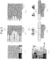
- Fig. 3 shows (1) a photograph of the structure before heat treatment, (2) a schematic image of the structure before heat treatment and (3) a schematic image of the structure after heat treatment, with respect to (A) a conventional sintered magnet and (B) a nanocrystalline magnet of the present invention.
- the shaded crystal grains and the gray crystal grains are reversed in magnetization direction.
- the grain boundary phase is unevenly distributed at triple points of the crystal grain boundary, and a grain boundary phase does not exist or exists in a very small amount in the grain boundary other than at the triple points. Accordingly, the grain boundary does not act as a barrier against the movement of magnetic domain walls, and since the magnetic domain walls move to the adjacent crystal grains across the crystal grain boundary, a high magnetic coercive force is not obtained.
- the grain boundary diffuses or fluidizes from the triple points, and sufficiently permeates the grain boundary other than the triple points to cover the entire crystal grain.
- the grain boundary phase exists in a sufficient amount in the grain boundary to prevent the movement of magnetic domain walls, and thereby the magnetic coercive force is enhanced.
- the grain boundary is unevenly distributed at the triple points of the crystal gain boundary, and a grain boundary phase does not exist or exists in a very small amount in the grain boundary other than the triplet point. Accordingly, the grain boundary does not act as a barrier against exchange coupling between adjacent crystal grains, and since adjacent crystal grains interact together through exchange coupling (2') to allow magnetization reversal in one crystal grain to induce magnetization reversal of the adjacent crystal grain, a high magnetic coercive force is not obtained.
- the grain boundary phase diffuses or fluidizes from the triple points, and sufficiently permeates the grain boundary other than the triple points to cover the entire crystal grain.
- the grain boundary phase exists in a sufficient amount in the grain boundary to prevent exchange coupling between adjacent crystal grains (3'), and therefore the magnetic coercive force is enhanced. Furthermore, due to a nanocrystalline structure, the grain boundary phase diffused or fluidized from the triple pints to cover the crystal grains in a very short time, so that the heat treatment time can be greatly reduced.
- an element capable of lowering the melting point of the grain boundary phase is added to the rare earth magnet composition.
- the rare earth magnet composition is represented by the formula R 1 v Fe w Co x B y M 1 z or R 2 a R 3 b Fe c Co d B e M 2 f
- an Nd-rich grain boundary phase is formed, for example when the rare earth magnet composition is represented by the formula Nd 15 Fe 77 B 7 Ga and the rare earth magnet is composed of a main phase Nd 2 Fe 14 B and an Nd-rich grain boundary phase
- an element capable of alloying with Nd and thereby lowering the temperature at which the grain boundary phase can be diffused or fluidized is added to the rare earth magnet composition above in an amount sufficiently large to bring about the effect of lowering the temperature and small enough to cause no deterioration of magnetic characteristics and hot workability.
- Ga has been conventionally used as an element having an effect of decreasing the crystal grain size, particularly for suppressing the crystal grain
- Examples of the elements capable of alloying with Nd and thereby lowering the temperature at which the grain boundary phase can be diffused or fluidized include Al, Cu, Mg, Fe, Co, Ag, Ni and Zn.
- addition of Cu is preferred in order to lower the melting point of the grain boundary phase.
- addition of Al does not greatly affect the magnetic characteristics, its addition in a small amount is preferred in the mass production process. This is because its addition can lower the optimal temperature (or can expand the temperature range) at the heat treatment for optimization, and, in turn, expand the temperature range for the production of a nanocrystalline magnet.
- the amount of such an additive element to be added can be from 0.05 to 0.5 atm%, preferably from 0.05 to 0.2 atm%.
- the finally obtained structure is a nanocrystalline structure composed of a main phase: Nd 2 Fe 14 B 1 phase, and a grain boundary phase: Nd-rich phase (Nd or Nd oxide) or Nd 1 Fe 4 B 4 phase.
- Ga is enriched in the grain boundary phase to prevent the movement of grain boundaries and suppress the coarsening of crystal grains.
- Both Al and Cu alloy with Nd in the grain boundary phase and enables diffusion or fluidization of the grain boundary phase.
- Each raw material of Nd, Fe, B, Ga, Al and Cu was weighed to a predetermined amount so as to give the two above-described compositions, and melted in an arc melting furnace to produce an alloy ingot.
- the alloy ingot was melted in a radio-frequency furnace, and the obtained molten alloy was quenched by ejecting it out on the roll surface of a copper-made single roll as shown in Fig. 1 .
- the conditions employed are as follows.
- the quenched flakes (4) were separated into nanocrystalline flakes and amorphous flakes by using a low magnetization magnet. More specifically, out of quenched flakes (4) of (1), amorphous quenched flakes were made of a soft magnetic material, and therefore easily magnetized by the magnet and kept from falling (2), whereas nanocrystalline quenched flakes were made of a hard magnetic material, and therefore not magnetized by the magnet and thus allowed to fall (3). Only fallen nanocrystalline quenched flakes were collected, and subjected to the following treatment.
- the obtained nanocrystalline quenched flakes were sintered by SPS under the following conditions.
- a low melting point phase was formed on one surface of the quenched flakes by the use of the single roll method, and this also contributes to the low-temperature sintering.
- the melting point of the main phase Nd 2 Fe 14 B 1 is 1,150°C
- the melting point of the low melting point phase is, for example, 1,021°C for Nd and 786°C for Nd 3 Ga.
- the above-described low-temperature sintering at 570°C could be achieved by the combination of the effect of lowering the sintering temperature due to the pressurization of the pressure sintering (surface pressure: 100 MPa), and the effect of lowering the sintering temperature due to the low melting point phase formed on one surface of the quenched flake.
- the obtained severely plastically deformed material was cut into a 2-mm square shape, and subjected to a heat treatment under the following conditions.
- Each of the samples comprising and not comprising Al and Cu was measured by VSM for magnetic characteristics, before and after heat treatment.
- Fig. 4 shows magnetization curves (demagnetization curves) of a rare earth magnet comprising Al and Cu as a typical example before and after heat treatment at 600°C. It is seen that the magnetic coercive force was enhanced by 15.92 ⁇ 10 4 A/m (2 kOe) from 132.14 ⁇ 10 4 A/m (16.6 kOe) to 148.06 ⁇ 10 4 A/m (18.6 kOe) by the heat treatment.
- the relationship between the change (%) of magnetic coercive force based on that before heat treatment, and the heat treatment temperature is shown in Fig. 5 and Table 1.
- the increase of magnetic coercive force by the heat treatment is seen in the heat treatment temperature range of 600 to 680°C.
- the ratio of increase is about 3% (about 3.98 ⁇ 10 4 A/m -0.5 kOe-) at a maximum.
- the increase of magnetic coercive force by the heat treatment is seen over a wide heat treatment temperature range of 450 to 700°C.
- the ratio of increase is about 13% at a maximum, and constitutes a significant rise.
- Table 1A Nd 15 Fe 77 B 7 Ga Temperature (°C) 300 450 475 500 525 550 600 650 675 700 Change of Magnetic coercive force (%) 98.3 91.6 90.5 90.5 90.8 92.7 100.3 102.3 101.2 94.9
- Table 1B Nd 15 Fe 77 B 6.8 Ga 0.5 Al 0.5 Cu 0.2 Temperature (°C) 400 450 500 550 600 650 700 725 Change of Magnetic coercive force (%) 97.8 101.5 104.1 107.9 112.2 112.4 102.1 95.8
- the temperature range wherein the magnetic coercive force is increased by the heat treatment appears to be expanded, and the increment of the magnetic coercive force is also enhanced.
- the eutectic temperature of Nd-Al or Nd-Cu is significantly lower than the melting point of Nd. That is, it is considered that diffusion or fluidization of the grain boundary phase is greatly accelerated by the introduction of Al and Cu into the grain boundary phase, and thereby the grain boundary phase is redistributed to the crystal grain boundary of the main phase Nd 2 Fe 14 B, and prevents the exchange coupling between main phase grains, as a result, the magnetic coercive force is increased.
- the relationship between the magnetic coercive force after heat treatment and the holding time (600°Cxt) is shown in Fig. 6 and Table 2.
- the magnetic coercive force before heat treatment is also shown. It is seen that the magnetic coercive force is enhanced by the heat treatment even for a short time of 10 seconds, and moreover, this effect is scarcely changed by the heat treatment up to 30 minutes.
- the holding time in the heat treatment must be from 1 to 10 hours so as to obtain a significant effect.
- the nanocrystalline magnet above has a crystal grain size of typically around 100 nm (0.1 ⁇ m), and the surface area of the crystal grain is smaller by about 2 orders of magnitude than a sintered magnet. For these reasons, the time required for the grain boundary phase to be diffused or fluidized by the heat treatment and cover the crystal grain is considered to be greatly reduced.
- the relationship between the magnetic coercive force after heat treatment and the heating rate upto the heat treatment temperature is shown in Fig. 7 and Table 3.
- the magnetic coercive force before heat treatment is also shown.
- the effect of enhancing the magnetic coercive force by the heat treatment shows almost no dependency on the temperature rising rate. In general, when the temperature rising rate is low, this has a risk of coarsening the structure and is considered as disadvantageous. A higher heating rate is preferred from the standpoint of suppressing the coarsening of the structure, and at the same time, reducing the processing time.
- Fig. 8 shows the TEM images before and after heat treatment.
- adjacent main phase grains are in direct contact with each other at the grain boundary without intervention of a grain boundary phase.
- the structure was changed such that, in many portions, an amorphous grain boundary phase is present at the grain boundary.
- the crystal grain size of the main phase was scarcely changed before and after the heat treatment, and was essentially constant.
- Fig. 9 shows the HAADF image and the EDX ray analysis results.
- the grain boundary before heat treatment appears white, and is considered to be an Nd-rich composition. The same is presumed from the EDX ray analysis results.
- the grain boundary after heat treatment appears black in the HAADF image, revealing that the electron density therein was decreased.
- the composition of the grain boundary phase after heat treatment is not Nd-rich as compared with the composition before heat treatment.
- Example 1 it is demonstrated that, according to the method of the present invention for producing a rare earth magnet wherein the heat treatment is associated with pressurization, a rare earth magnet having an improved magnetic coercive force as compared with the case of performing heat treatment with no pressurization is obtained.
- a nanocrystalline rare earth magnet of the composition Nd 16 Fe 77.4 B 5.4 Ga 0.5 Al 0.5 Cu 0.2 was produced.
- the finally obtained structure is a nanocrystalline structure composed of a main phase: Nd 2 Fe 14 B 1 phase, and a grain boundary phase: Nd-rich phase (Nd or Nd oxide) or Nd 1 Fe 4 B 4 phase.
- Ga is enriched in the grain boundary phase to block the movement of grain boundaries, and suppress the coarsening of crystal grains.
- Each raw material of Nd, Fe, FeB, Ga, Al and Cu was weighed to a predetermined amount so as to give the above-described composition, and melted in an arc melting furnace to produce an alloy ingot.
- the alloy ingot was melted in a radio-frequency furnace, and the obtained molten alloy was quenched by ejecting it out on the roll surface of a copper-made single roll, as shown in Fig. 1 .
- the conditions employed are as follows.
- the quenched flakes (4) were separated into nanocrystalline flakes and amorphous flakes by using a low magnetization magnet. More specifically, out of quenched flakes (4) of (1), amorphous quenched flakes were made of a soft magnetic material, and therefore magnetized by the magnet and kept from falling (2), whereas nanocrystalline quenched flakes were made of a hard magnetic material, and therefore not magnetized by the magnet and thus allowed to fall (3). Only fallen nanocrystalline quenched flakes were collected, and subjected to the following treatment.
- the obtained nanocrystalline quenched flakes were sintered by SPS under the following conditions.
- a low melting point phase was formed on one surface of the quenched flake by the use of the single roll method, and this also contributes to the low-temperature sintering.
- the melting point of the main phase Nd 2 Fe 14 B 1 is 1,150°C
- the melting point of the low melting point phase is, for example, 1,021°C for Nd and 786°C for Nd 3 Ga.
- the above-described low-temperature sintering at 570°C could be achieved by the combination of the effect of lowering the sintering temperature due to the pressurization of the pressure sintering (surface pressure: 100 MPa), and the effect of lowering the sintering temperature due to the low melting point phase formed on one surface of the quenched flake.
- Fig. 10 shows magnetization curves (demagnetization curves) of samples before heat treatment, after heat treatment with no pressurization, and after heat treatment with pressurization at 40 MPa.
- Fig. 11 shows the relationship between the magnetic coercive force before heat treatment or after heat treatment (pressure: 0 MPa, 10 MPa, or 40 MPa), and the pressure at the heat treatment. It is seen from these Figures that the magnetic coercive force was enhanced by the heat treatment, and, in the case of heat treatment with pressurization, the magnetic coercive force was further enhanced in comparison to the heat treatment with no pressurization.
- Example 2 the extrusion (pushing-out) effect on the grain boundary phase by pressurization during the heat treatment is demonstrated.
- a Ta buffer layer was deposited on a Si substrate, a NdFeB layer having a thickness of roughly 5 ⁇ m was deposited on the Ta buffer layer, and a Ta cap layer was deposited on the NdFeB layer. All depositions were performed at 450°C using high rate sputtering.
- Heat treatment of crystallization was performed at 750°C. Thereafter, the magnetic characteristics were evaluated by Vibrating Sample Magnetometry, and the microstructure was observed by SEM.
- Figs. 12 and 15 show the cross-sectional SEM images and coercivity measurements of the NdFeB layers. From this Figure, it can be seen that the low coercivity(143.3 ⁇ 10 4 A/m) film has a poor quality buffer layer - substrate interface, and that the magnetic film has almost fully peeled off the substrate. The degradation of the interface is attributed to diffusion between the Ta layer and the substrate. On the other hand, the high coercivity(207 ⁇ 10 4 A/m) film has an intact buffer layer - substrate interface, so that the film is rigidly attached to the substrate.
- a difference in thermal expansion coefficients of the substrate and the magnetic film together with phase transformations in the magnetic film during the annealing process leads to a build up of compressive stress in the hard magnetic film.
- the compressive stress is relaxed.
- measurement of substrate-film curvature by optical interferometry indicates that the high coercivity film is under a compressive stress of about 250 MPa.
- the Nd-rich phase becomes liquid during the post-deposition annealing step.
- the high level of compressive stress in the fully adhered film leads to a squeezing out of some of the Nd-rich phase from the hard magnetic layer, which in turn creates ripples in the Ta capping layer ( Fig. 14 (a) ).
- Figs. 14(a) and 14(b) are SEM images (secondary electron image).
- the extrusion of the Nd-rich phase which leads to the formation of surface ripples, also serves to redistribute the Nd-rich phase around the solid Nd 2 Fe 14 B grains.
- the improvement of the magnetic coercive force is attributable to the fact that the grain boundary phase, which is unevenly distributed mainly in triple points among crystal grains of the main phase, is extruded from the triple points due to a compressive stress, and thereby diffusion or fluidization of the grain boundary phase can be accelerated.
- a production method of a rare earth magnet which is usually represented by a neodymium magnet (Nd 2 Fe 14 B) is provided, wherein a heat treatment method capable of enhancing the magnetic characteristics, particularly the magnetic coercive force, is used.
Landscapes
- Engineering & Computer Science (AREA)
- Chemical & Material Sciences (AREA)
- Power Engineering (AREA)
- Materials Engineering (AREA)
- Mechanical Engineering (AREA)
- Metallurgy (AREA)
- Organic Chemistry (AREA)
- Manufacturing & Machinery (AREA)
- Hard Magnetic Materials (AREA)
- Manufacturing Cores, Coils, And Magnets (AREA)
- Powder Metallurgy (AREA)
Priority Applications (5)
| Application Number | Priority Date | Filing Date | Title |
|---|---|---|---|
| EP10306166.9A EP2444985B1 (en) | 2010-10-25 | 2010-10-25 | Production method of rare earth magnet |
| JP2013516808A JP5933535B2 (ja) | 2010-10-25 | 2011-05-13 | 希土類磁石の製造方法 |
| US13/824,572 US9520230B2 (en) | 2010-10-25 | 2011-05-13 | Production method of rare earth magnet |
| CN201180049051.8A CN103189943B (zh) | 2010-10-25 | 2011-05-13 | 稀土磁体的制备方法 |
| PCT/JP2011/061608 WO2012056755A1 (en) | 2010-10-25 | 2011-05-13 | Production method of rare earth magnet |
Applications Claiming Priority (1)
| Application Number | Priority Date | Filing Date | Title |
|---|---|---|---|
| EP10306166.9A EP2444985B1 (en) | 2010-10-25 | 2010-10-25 | Production method of rare earth magnet |
Publications (2)
| Publication Number | Publication Date |
|---|---|
| EP2444985A1 EP2444985A1 (en) | 2012-04-25 |
| EP2444985B1 true EP2444985B1 (en) | 2018-07-11 |
Family
ID=43272396
Family Applications (1)
| Application Number | Title | Priority Date | Filing Date |
|---|---|---|---|
| EP10306166.9A Active EP2444985B1 (en) | 2010-10-25 | 2010-10-25 | Production method of rare earth magnet |
Country Status (5)
| Country | Link |
|---|---|
| US (1) | US9520230B2 (zh) |
| EP (1) | EP2444985B1 (zh) |
| JP (1) | JP5933535B2 (zh) |
| CN (1) | CN103189943B (zh) |
| WO (1) | WO2012056755A1 (zh) |
Families Citing this family (17)
| Publication number | Priority date | Publication date | Assignee | Title |
|---|---|---|---|---|
| WO2013103132A1 (ja) * | 2012-01-04 | 2013-07-11 | トヨタ自動車株式会社 | 希土類ナノコンポジット磁石 |
| WO2013137857A2 (en) | 2012-03-12 | 2013-09-19 | The Massachusetts Institute Of Technology | Stable binary nanocrystalline alloys and methods of identifying same |
| WO2014152838A1 (en) | 2013-03-14 | 2014-09-25 | Massachusetts Institute Of Technology | Sintered nanocrystalline alloys |
| KR20150033423A (ko) * | 2013-09-24 | 2015-04-01 | 엘지전자 주식회사 | 열간가압성형 공정을 이용한 이방성 열간가압성형 자석의 제조방법 및 이 방법으로 제조된 열간가압성형 자석 |
| JP5915637B2 (ja) | 2013-12-19 | 2016-05-11 | トヨタ自動車株式会社 | 希土類磁石の製造方法 |
| JP5924335B2 (ja) | 2013-12-26 | 2016-05-25 | トヨタ自動車株式会社 | 希土類磁石とその製造方法 |
| WO2016067949A1 (ja) * | 2014-10-27 | 2016-05-06 | Jx金属株式会社 | 希土類薄膜磁石及びその製造方法 |
| US11644288B2 (en) | 2015-09-17 | 2023-05-09 | Massachusetts Institute Of Technology | Nanocrystalline alloy penetrators |
| JP6848735B2 (ja) * | 2016-07-15 | 2021-03-24 | Tdk株式会社 | R−t−b系希土類永久磁石 |
| JP6604321B2 (ja) * | 2016-12-27 | 2019-11-13 | トヨタ自動車株式会社 | 希土類磁石の製造方法 |
| US11173615B2 (en) | 2017-03-30 | 2021-11-16 | Soft Robotics, Inc. | User-assisted robotic control systems |
| CN109979743B (zh) * | 2017-12-27 | 2022-03-04 | 宁波科宁达工业有限公司 | 一种钕铁硼磁体晶界扩散的方法及稀土磁体 |
| JP7110662B2 (ja) * | 2018-03-28 | 2022-08-02 | Tdk株式会社 | R‐t‐b系焼結磁石 |
| US11004600B2 (en) | 2018-06-19 | 2021-05-11 | Ford Global Technologies, Llc | Permanent magnet and method of making permanent magnet |
| CN112053824B (zh) * | 2019-06-05 | 2023-08-22 | 中国科学院宁波材料技术与工程研究所 | 一种烧结钕铁硼永磁体及其制备方法 |
| CN114287046A (zh) * | 2019-08-26 | 2022-04-05 | 日本电产株式会社 | 马达、驱动系统、吸尘器、无人飞行体、电动航空器 |
| CN112908667B (zh) * | 2020-06-29 | 2022-07-15 | 京磁材料科技股份有限公司 | 稀土永磁体的晶界扩散方法 |
Family Cites Families (18)
| Publication number | Priority date | Publication date | Assignee | Title |
|---|---|---|---|---|
| FR2598949B1 (fr) * | 1986-05-23 | 1989-08-04 | Centre Nat Rech Scient | Procede pour la preparation de cristaux finement divises a partir d'un alliage metallique, notamment pour la preparation d'aimants permanents |
| US5405455A (en) | 1991-06-04 | 1995-04-11 | Shin-Etsu Chemical Co. Ltd. | Rare earth-based permanent magnet |
| JP2853839B2 (ja) | 1991-06-04 | 1999-02-03 | 信越化学工業株式会社 | 希土類永久磁石の製造方法 |
| JP2853838B2 (ja) | 1991-06-04 | 1999-02-03 | 信越化学工業株式会社 | 希土類永久磁石の製造方法 |
| DE69837590T2 (de) * | 1997-06-26 | 2007-10-04 | Neomax Co., Ltd. | Verfahren zur herstellung von laminierten dauermagneten |
| US6511552B1 (en) * | 1998-03-23 | 2003-01-28 | Sumitomo Special Metals Co., Ltd. | Permanent magnets and R-TM-B based permanent magnets |
| JP4337209B2 (ja) * | 2000-02-22 | 2009-09-30 | 日立金属株式会社 | 永久磁石薄膜およびその製造方法 |
| CN1212626C (zh) * | 2001-05-15 | 2005-07-27 | 株式会社新王磁材 | 铁基稀土合金纳米复合磁体及其制造方法 |
| CN1735947A (zh) | 2002-05-24 | 2006-02-15 | 代顿大学 | 纳米晶态和纳米复合稀土永磁体材料及其制造方法 |
| US20040025974A1 (en) | 2002-05-24 | 2004-02-12 | Don Lee | Nanocrystalline and nanocomposite rare earth permanent magnet materials and method of making the same |
| US7919200B2 (en) * | 2005-06-10 | 2011-04-05 | Nissan Motor Co., Ltd. | Rare earth magnet having high strength and high electrical resistance |
| CN101689416B (zh) * | 2007-05-02 | 2012-10-03 | 日立金属株式会社 | R-t-b系烧结磁体 |
| EP2228808B1 (en) * | 2007-11-02 | 2017-01-04 | Asahi Kasei Kabushiki Kaisha | Composite magnetic material for magnet and method for manufacturing such material |
| JP5532745B2 (ja) | 2009-08-21 | 2014-06-25 | 大同特殊鋼株式会社 | 磁気異方性磁石及びその製造方法 |
| EP2099039A1 (en) | 2008-02-29 | 2009-09-09 | Daido Steel Co.,Ltd. | Material for magnetic anisotropic magnet |
| JP2010263172A (ja) | 2008-07-04 | 2010-11-18 | Daido Steel Co Ltd | 希土類磁石およびその製造方法 |
| CN104143402B (zh) * | 2009-01-07 | 2017-05-24 | 大同特殊钢株式会社 | 磁各向异性磁体原材料 |
| WO2012008623A1 (ja) | 2010-07-16 | 2012-01-19 | トヨタ自動車株式会社 | 希土類磁石の製造方法、及び希土類磁石 |
-
2010
- 2010-10-25 EP EP10306166.9A patent/EP2444985B1/en active Active
-
2011
- 2011-05-13 WO PCT/JP2011/061608 patent/WO2012056755A1/en active Application Filing
- 2011-05-13 CN CN201180049051.8A patent/CN103189943B/zh not_active Expired - Fee Related
- 2011-05-13 US US13/824,572 patent/US9520230B2/en active Active
- 2011-05-13 JP JP2013516808A patent/JP5933535B2/ja active Active
Non-Patent Citations (1)
| Title |
|---|
| None * |
Also Published As
| Publication number | Publication date |
|---|---|
| US9520230B2 (en) | 2016-12-13 |
| EP2444985A1 (en) | 2012-04-25 |
| CN103189943B (zh) | 2016-05-04 |
| JP2014502034A (ja) | 2014-01-23 |
| US20130248754A1 (en) | 2013-09-26 |
| JP5933535B2 (ja) | 2016-06-08 |
| CN103189943A (zh) | 2013-07-03 |
| WO2012056755A1 (en) | 2012-05-03 |
Similar Documents
| Publication | Publication Date | Title |
|---|---|---|
| EP2444985B1 (en) | Production method of rare earth magnet | |
| CN107871582B (zh) | R-Fe-B烧结磁体 | |
| CN107871581B (zh) | 制备R-Fe-B烧结磁体的方法 | |
| CN106710766B (zh) | R-(Fe,Co)-B烧结磁体及制造方法 | |
| TWI673730B (zh) | R-Fe-B系燒結磁石及其製造方法 | |
| EP2752857B1 (en) | R-T-B rare earth sintered magnet | |
| EP2043114B1 (en) | R-fe-b microcrystalline high-density magnet and process for production thereof | |
| EP1780736B1 (en) | R-T-B type alloy, production method of R-T-B type alloy flake, fine powder for R-T-B type rare earth permanent magnet, and R-T-B type rare earth permanent magnet | |
| JP5692231B2 (ja) | 希土類磁石の製造方法、及び希土類磁石 | |
| EP2141710A1 (en) | Rare earth magnet and production process thereof | |
| JP5472236B2 (ja) | 希土類磁石の製造方法、及び希土類磁石 | |
| CN108352231B (zh) | 稀土-钴永磁体 | |
| US10878981B2 (en) | R-T-B based permanent magnet | |
| EP3441988A1 (en) | A sintered r-t-b based permanent magnet | |
| JP5708242B2 (ja) | 希土類磁石の製造方法 | |
| EP1479787B1 (en) | Sinter magnet made from rare earth-iron-boron alloy powder for magnet | |
| EP3106536B1 (en) | Rare earth-containing alloy flakes and manufacturing method thereof | |
| JP2024020341A (ja) | 異方性希土類焼結磁石及びその製造方法 | |
| JPH0768561B2 (ja) | 希土類−Fe−B系合金磁石粉末の製造法 | |
| CN113223797A (zh) | 稀土钴永磁体、其制造方法和装置 | |
| US20190311851A1 (en) | Method of producing nd-fe-b magnet | |
| WO2019078148A1 (ja) | 希土類磁石素材および希土類磁石 | |
| JPH08273914A (ja) | 希土類磁石およびその製造方法 | |
| JP7256483B2 (ja) | R-t-b系永久磁石およびその製造方法 | |
| JP7017757B2 (ja) | 希土類永久磁石 |
Legal Events
| Date | Code | Title | Description |
|---|---|---|---|
| 17P | Request for examination filed |
Effective date: 20101215 |
|
| AK | Designated contracting states |
Kind code of ref document: A1 Designated state(s): AL AT BE BG CH CY CZ DE DK EE ES FI FR GB GR HR HU IE IS IT LI LT LU LV MC MK MT NL NO PL PT RO RS SE SI SK SM TR |
|
| AX | Request for extension of the european patent |
Extension state: BA ME |
|
| PUAI | Public reference made under article 153(3) epc to a published international application that has entered the european phase |
Free format text: ORIGINAL CODE: 0009012 |
|
| RAP1 | Party data changed (applicant data changed or rights of an application transferred) |
Owner name: CENTRE NATIONAL DE LA RECHERCHE SCIENTIFIQUE Owner name: UNIVERSITY OF SHEFFIELD Owner name: TOYOTA JIDOSHA KABUSHIKI KAISHA Owner name: LEIBNIZ-INSTITUT FUER FESTKOERPER- UND WERKSTOFFFO |
|
| 17Q | First examination report despatched |
Effective date: 20140930 |
|
| GRAP | Despatch of communication of intention to grant a patent |
Free format text: ORIGINAL CODE: EPIDOSNIGR1 |
|
| INTG | Intention to grant announced |
Effective date: 20160802 |
|
| GRAJ | Information related to disapproval of communication of intention to grant by the applicant or resumption of examination proceedings by the epo deleted |
Free format text: ORIGINAL CODE: EPIDOSDIGR1 |
|
| INTC | Intention to grant announced (deleted) | ||
| GRAP | Despatch of communication of intention to grant a patent |
Free format text: ORIGINAL CODE: EPIDOSNIGR1 |
|
| INTG | Intention to grant announced |
Effective date: 20180130 |
|
| GRAS | Grant fee paid |
Free format text: ORIGINAL CODE: EPIDOSNIGR3 |
|
| GRAA | (expected) grant |
Free format text: ORIGINAL CODE: 0009210 |
|
| AK | Designated contracting states |
Kind code of ref document: B1 Designated state(s): AL AT BE BG CH CY CZ DE DK EE ES FI FR GB GR HR HU IE IS IT LI LT LU LV MC MK MT NL NO PL PT RO RS SE SI SK SM TR |
|
| REG | Reference to a national code |
Ref country code: GB Ref legal event code: FG4D |
|
| REG | Reference to a national code |
Ref country code: CH Ref legal event code: EP |
|
| REG | Reference to a national code |
Ref country code: AT Ref legal event code: REF Ref document number: 1017775 Country of ref document: AT Kind code of ref document: T Effective date: 20180715 |
|
| REG | Reference to a national code |
Ref country code: IE Ref legal event code: FG4D |
|
| REG | Reference to a national code |
Ref country code: DE Ref legal event code: R096 Ref document number: 602010051789 Country of ref document: DE |
|
| REG | Reference to a national code |
Ref country code: FR Ref legal event code: PLFP Year of fee payment: 9 |
|
| REG | Reference to a national code |
Ref country code: NL Ref legal event code: MP Effective date: 20180711 |
|
| REG | Reference to a national code |
Ref country code: LT Ref legal event code: MG4D |
|
| REG | Reference to a national code |
Ref country code: AT Ref legal event code: MK05 Ref document number: 1017775 Country of ref document: AT Kind code of ref document: T Effective date: 20180711 |
|
| PG25 | Lapsed in a contracting state [announced via postgrant information from national office to epo] |
Ref country code: NL Free format text: LAPSE BECAUSE OF FAILURE TO SUBMIT A TRANSLATION OF THE DESCRIPTION OR TO PAY THE FEE WITHIN THE PRESCRIBED TIME-LIMIT Effective date: 20180711 |
|
| PG25 | Lapsed in a contracting state [announced via postgrant information from national office to epo] |
Ref country code: BG Free format text: LAPSE BECAUSE OF FAILURE TO SUBMIT A TRANSLATION OF THE DESCRIPTION OR TO PAY THE FEE WITHIN THE PRESCRIBED TIME-LIMIT Effective date: 20181011 Ref country code: SE Free format text: LAPSE BECAUSE OF FAILURE TO SUBMIT A TRANSLATION OF THE DESCRIPTION OR TO PAY THE FEE WITHIN THE PRESCRIBED TIME-LIMIT Effective date: 20180711 Ref country code: LT Free format text: LAPSE BECAUSE OF FAILURE TO SUBMIT A TRANSLATION OF THE DESCRIPTION OR TO PAY THE FEE WITHIN THE PRESCRIBED TIME-LIMIT Effective date: 20180711 Ref country code: PL Free format text: LAPSE BECAUSE OF FAILURE TO SUBMIT A TRANSLATION OF THE DESCRIPTION OR TO PAY THE FEE WITHIN THE PRESCRIBED TIME-LIMIT Effective date: 20180711 Ref country code: FI Free format text: LAPSE BECAUSE OF FAILURE TO SUBMIT A TRANSLATION OF THE DESCRIPTION OR TO PAY THE FEE WITHIN THE PRESCRIBED TIME-LIMIT Effective date: 20180711 Ref country code: IS Free format text: LAPSE BECAUSE OF FAILURE TO SUBMIT A TRANSLATION OF THE DESCRIPTION OR TO PAY THE FEE WITHIN THE PRESCRIBED TIME-LIMIT Effective date: 20181111 Ref country code: RS Free format text: LAPSE BECAUSE OF FAILURE TO SUBMIT A TRANSLATION OF THE DESCRIPTION OR TO PAY THE FEE WITHIN THE PRESCRIBED TIME-LIMIT Effective date: 20180711 Ref country code: AT Free format text: LAPSE BECAUSE OF FAILURE TO SUBMIT A TRANSLATION OF THE DESCRIPTION OR TO PAY THE FEE WITHIN THE PRESCRIBED TIME-LIMIT Effective date: 20180711 Ref country code: GR Free format text: LAPSE BECAUSE OF FAILURE TO SUBMIT A TRANSLATION OF THE DESCRIPTION OR TO PAY THE FEE WITHIN THE PRESCRIBED TIME-LIMIT Effective date: 20181012 Ref country code: NO Free format text: LAPSE BECAUSE OF FAILURE TO SUBMIT A TRANSLATION OF THE DESCRIPTION OR TO PAY THE FEE WITHIN THE PRESCRIBED TIME-LIMIT Effective date: 20181011 |
|
| PG25 | Lapsed in a contracting state [announced via postgrant information from national office to epo] |
Ref country code: AL Free format text: LAPSE BECAUSE OF FAILURE TO SUBMIT A TRANSLATION OF THE DESCRIPTION OR TO PAY THE FEE WITHIN THE PRESCRIBED TIME-LIMIT Effective date: 20180711 Ref country code: ES Free format text: LAPSE BECAUSE OF FAILURE TO SUBMIT A TRANSLATION OF THE DESCRIPTION OR TO PAY THE FEE WITHIN THE PRESCRIBED TIME-LIMIT Effective date: 20180711 Ref country code: HR Free format text: LAPSE BECAUSE OF FAILURE TO SUBMIT A TRANSLATION OF THE DESCRIPTION OR TO PAY THE FEE WITHIN THE PRESCRIBED TIME-LIMIT Effective date: 20180711 Ref country code: LV Free format text: LAPSE BECAUSE OF FAILURE TO SUBMIT A TRANSLATION OF THE DESCRIPTION OR TO PAY THE FEE WITHIN THE PRESCRIBED TIME-LIMIT Effective date: 20180711 |
|
| REG | Reference to a national code |
Ref country code: DE Ref legal event code: R097 Ref document number: 602010051789 Country of ref document: DE |
|
| PG25 | Lapsed in a contracting state [announced via postgrant information from national office to epo] |
Ref country code: RO Free format text: LAPSE BECAUSE OF FAILURE TO SUBMIT A TRANSLATION OF THE DESCRIPTION OR TO PAY THE FEE WITHIN THE PRESCRIBED TIME-LIMIT Effective date: 20180711 Ref country code: IT Free format text: LAPSE BECAUSE OF FAILURE TO SUBMIT A TRANSLATION OF THE DESCRIPTION OR TO PAY THE FEE WITHIN THE PRESCRIBED TIME-LIMIT Effective date: 20180711 Ref country code: EE Free format text: LAPSE BECAUSE OF FAILURE TO SUBMIT A TRANSLATION OF THE DESCRIPTION OR TO PAY THE FEE WITHIN THE PRESCRIBED TIME-LIMIT Effective date: 20180711 Ref country code: CZ Free format text: LAPSE BECAUSE OF FAILURE TO SUBMIT A TRANSLATION OF THE DESCRIPTION OR TO PAY THE FEE WITHIN THE PRESCRIBED TIME-LIMIT Effective date: 20180711 |
|
| PLBE | No opposition filed within time limit |
Free format text: ORIGINAL CODE: 0009261 |
|
| STAA | Information on the status of an ep patent application or granted ep patent |
Free format text: STATUS: NO OPPOSITION FILED WITHIN TIME LIMIT |
|
| PG25 | Lapsed in a contracting state [announced via postgrant information from national office to epo] |
Ref country code: SK Free format text: LAPSE BECAUSE OF FAILURE TO SUBMIT A TRANSLATION OF THE DESCRIPTION OR TO PAY THE FEE WITHIN THE PRESCRIBED TIME-LIMIT Effective date: 20180711 Ref country code: DK Free format text: LAPSE BECAUSE OF FAILURE TO SUBMIT A TRANSLATION OF THE DESCRIPTION OR TO PAY THE FEE WITHIN THE PRESCRIBED TIME-LIMIT Effective date: 20180711 Ref country code: SM Free format text: LAPSE BECAUSE OF FAILURE TO SUBMIT A TRANSLATION OF THE DESCRIPTION OR TO PAY THE FEE WITHIN THE PRESCRIBED TIME-LIMIT Effective date: 20180711 |
|
| REG | Reference to a national code |
Ref country code: CH Ref legal event code: PL |
|
| 26N | No opposition filed |
Effective date: 20190412 |
|
| GBPC | Gb: european patent ceased through non-payment of renewal fee |
Effective date: 20181025 |
|
| REG | Reference to a national code |
Ref country code: BE Ref legal event code: MM Effective date: 20181031 |
|
| PG25 | Lapsed in a contracting state [announced via postgrant information from national office to epo] |
Ref country code: MC Free format text: LAPSE BECAUSE OF FAILURE TO SUBMIT A TRANSLATION OF THE DESCRIPTION OR TO PAY THE FEE WITHIN THE PRESCRIBED TIME-LIMIT Effective date: 20180711 Ref country code: LU Free format text: LAPSE BECAUSE OF NON-PAYMENT OF DUE FEES Effective date: 20181025 |
|
| REG | Reference to a national code |
Ref country code: IE Ref legal event code: MM4A |
|
| PG25 | Lapsed in a contracting state [announced via postgrant information from national office to epo] |
Ref country code: BE Free format text: LAPSE BECAUSE OF NON-PAYMENT OF DUE FEES Effective date: 20181031 Ref country code: CH Free format text: LAPSE BECAUSE OF NON-PAYMENT OF DUE FEES Effective date: 20181031 Ref country code: SI Free format text: LAPSE BECAUSE OF FAILURE TO SUBMIT A TRANSLATION OF THE DESCRIPTION OR TO PAY THE FEE WITHIN THE PRESCRIBED TIME-LIMIT Effective date: 20180711 Ref country code: LI Free format text: LAPSE BECAUSE OF NON-PAYMENT OF DUE FEES Effective date: 20181031 |
|
| PG25 | Lapsed in a contracting state [announced via postgrant information from national office to epo] |
Ref country code: GB Free format text: LAPSE BECAUSE OF NON-PAYMENT OF DUE FEES Effective date: 20181025 Ref country code: IE Free format text: LAPSE BECAUSE OF NON-PAYMENT OF DUE FEES Effective date: 20181025 |
|
| PG25 | Lapsed in a contracting state [announced via postgrant information from national office to epo] |
Ref country code: MT Free format text: LAPSE BECAUSE OF NON-PAYMENT OF DUE FEES Effective date: 20181025 |
|
| PG25 | Lapsed in a contracting state [announced via postgrant information from national office to epo] |
Ref country code: TR Free format text: LAPSE BECAUSE OF FAILURE TO SUBMIT A TRANSLATION OF THE DESCRIPTION OR TO PAY THE FEE WITHIN THE PRESCRIBED TIME-LIMIT Effective date: 20180711 |
|
| PG25 | Lapsed in a contracting state [announced via postgrant information from national office to epo] |
Ref country code: PT Free format text: LAPSE BECAUSE OF FAILURE TO SUBMIT A TRANSLATION OF THE DESCRIPTION OR TO PAY THE FEE WITHIN THE PRESCRIBED TIME-LIMIT Effective date: 20180711 |
|
| PG25 | Lapsed in a contracting state [announced via postgrant information from national office to epo] |
Ref country code: CY Free format text: LAPSE BECAUSE OF FAILURE TO SUBMIT A TRANSLATION OF THE DESCRIPTION OR TO PAY THE FEE WITHIN THE PRESCRIBED TIME-LIMIT Effective date: 20180711 Ref country code: MK Free format text: LAPSE BECAUSE OF NON-PAYMENT OF DUE FEES Effective date: 20180711 Ref country code: HU Free format text: LAPSE BECAUSE OF FAILURE TO SUBMIT A TRANSLATION OF THE DESCRIPTION OR TO PAY THE FEE WITHIN THE PRESCRIBED TIME-LIMIT; INVALID AB INITIO Effective date: 20101025 |
|
| PGFP | Annual fee paid to national office [announced via postgrant information from national office to epo] |
Ref country code: FR Payment date: 20220908 Year of fee payment: 13 |
|
| PGFP | Annual fee paid to national office [announced via postgrant information from national office to epo] |
Ref country code: DE Payment date: 20220831 Year of fee payment: 13 |