EP2432648B1 - Absaugband - Google Patents
Absaugband Download PDFInfo
- Publication number
- EP2432648B1 EP2432648B1 EP11718097A EP11718097A EP2432648B1 EP 2432648 B1 EP2432648 B1 EP 2432648B1 EP 11718097 A EP11718097 A EP 11718097A EP 11718097 A EP11718097 A EP 11718097A EP 2432648 B1 EP2432648 B1 EP 2432648B1
- Authority
- EP
- European Patent Office
- Prior art keywords
- suction belt
- area
- suction
- belt
- envelope
- Prior art date
- Legal status (The legal status is an assumption and is not a legal conclusion. Google has not performed a legal analysis and makes no representation as to the accuracy of the status listed.)
- Active
Links
Images



Classifications
-
- B—PERFORMING OPERATIONS; TRANSPORTING
- B65—CONVEYING; PACKING; STORING; HANDLING THIN OR FILAMENTARY MATERIAL
- B65B—MACHINES, APPARATUS OR DEVICES FOR, OR METHODS OF, PACKAGING ARTICLES OR MATERIALS; UNPACKING
- B65B35/00—Supplying, feeding, arranging or orientating articles to be packaged
- B65B35/56—Orientating, i.e. changing the attitude of, articles, e.g. of non-uniform cross-section
-
- B—PERFORMING OPERATIONS; TRANSPORTING
- B43—WRITING OR DRAWING IMPLEMENTS; BUREAU ACCESSORIES
- B43M—BUREAU ACCESSORIES NOT OTHERWISE PROVIDED FOR
- B43M3/00—Devices for inserting documents into envelopes
- B43M3/04—Devices for inserting documents into envelopes automatic
-
- B—PERFORMING OPERATIONS; TRANSPORTING
- B43—WRITING OR DRAWING IMPLEMENTS; BUREAU ACCESSORIES
- B43M—BUREAU ACCESSORIES NOT OTHERWISE PROVIDED FOR
- B43M3/00—Devices for inserting documents into envelopes
- B43M3/04—Devices for inserting documents into envelopes automatic
- B43M3/045—Devices for inserting documents into envelopes automatic for envelopes with only one flap
-
- B—PERFORMING OPERATIONS; TRANSPORTING
- B65—CONVEYING; PACKING; STORING; HANDLING THIN OR FILAMENTARY MATERIAL
- B65B—MACHINES, APPARATUS OR DEVICES FOR, OR METHODS OF, PACKAGING ARTICLES OR MATERIALS; UNPACKING
- B65B5/00—Packaging individual articles in containers or receptacles, e.g. bags, sacks, boxes, cartons, cans, jars
-
- B—PERFORMING OPERATIONS; TRANSPORTING
- B65—CONVEYING; PACKING; STORING; HANDLING THIN OR FILAMENTARY MATERIAL
- B65B—MACHINES, APPARATUS OR DEVICES FOR, OR METHODS OF, PACKAGING ARTICLES OR MATERIALS; UNPACKING
- B65B5/00—Packaging individual articles in containers or receptacles, e.g. bags, sacks, boxes, cartons, cans, jars
- B65B5/04—Packaging single articles
-
- B—PERFORMING OPERATIONS; TRANSPORTING
- B65—CONVEYING; PACKING; STORING; HANDLING THIN OR FILAMENTARY MATERIAL
- B65G—TRANSPORT OR STORAGE DEVICES, e.g. CONVEYORS FOR LOADING OR TIPPING, SHOP CONVEYOR SYSTEMS OR PNEUMATIC TUBE CONVEYORS
- B65G15/00—Conveyors having endless load-conveying surfaces, i.e. belts and like continuous members, to which tractive effort is transmitted by means other than endless driving elements of similar configuration
- B65G15/30—Belts or like endless load-carriers
- B65G15/58—Belts or like endless load-carriers with means for holding or retaining the loads in fixed position, e.g. magnetic
-
- B—PERFORMING OPERATIONS; TRANSPORTING
- B65—CONVEYING; PACKING; STORING; HANDLING THIN OR FILAMENTARY MATERIAL
- B65H—HANDLING THIN OR FILAMENTARY MATERIAL, e.g. SHEETS, WEBS, CABLES
- B65H11/00—Feed tables
- B65H11/002—Feed tables incorporating transport belts
- B65H11/005—Suction belts
-
- B—PERFORMING OPERATIONS; TRANSPORTING
- B65—CONVEYING; PACKING; STORING; HANDLING THIN OR FILAMENTARY MATERIAL
- B65H—HANDLING THIN OR FILAMENTARY MATERIAL, e.g. SHEETS, WEBS, CABLES
- B65H29/00—Delivering or advancing articles from machines; Advancing articles to or into piles
- B65H29/24—Delivering or advancing articles from machines; Advancing articles to or into piles by air blast or suction apparatus
- B65H29/241—Suction devices
- B65H29/242—Suction bands or belts
-
- B—PERFORMING OPERATIONS; TRANSPORTING
- B65—CONVEYING; PACKING; STORING; HANDLING THIN OR FILAMENTARY MATERIAL
- B65H—HANDLING THIN OR FILAMENTARY MATERIAL, e.g. SHEETS, WEBS, CABLES
- B65H2404/00—Parts for transporting or guiding the handled material
- B65H2404/20—Belts
- B65H2404/22—Cross section profile
-
- B—PERFORMING OPERATIONS; TRANSPORTING
- B65—CONVEYING; PACKING; STORING; HANDLING THIN OR FILAMENTARY MATERIAL
- B65H—HANDLING THIN OR FILAMENTARY MATERIAL, e.g. SHEETS, WEBS, CABLES
- B65H2404/00—Parts for transporting or guiding the handled material
- B65H2404/20—Belts
- B65H2404/23—Belts with auxiliary handling means
- B65H2404/232—Blade, plate, finger
-
- B—PERFORMING OPERATIONS; TRANSPORTING
- B65—CONVEYING; PACKING; STORING; HANDLING THIN OR FILAMENTARY MATERIAL
- B65H—HANDLING THIN OR FILAMENTARY MATERIAL, e.g. SHEETS, WEBS, CABLES
- B65H2404/00—Parts for transporting or guiding the handled material
- B65H2404/20—Belts
- B65H2404/24—Longitudinal profile
- B65H2404/243—Longitudinal profile with portions of different thickness
-
- B—PERFORMING OPERATIONS; TRANSPORTING
- B65—CONVEYING; PACKING; STORING; HANDLING THIN OR FILAMENTARY MATERIAL
- B65H—HANDLING THIN OR FILAMENTARY MATERIAL, e.g. SHEETS, WEBS, CABLES
- B65H2406/00—Means using fluid
- B65H2406/30—Suction means
- B65H2406/32—Suction belts
- B65H2406/322—Suction distributing means
- B65H2406/3223—Suction distributing means details of the openings in the belt, e.g. shape, distribution
- B65H2406/32231—Suction distributing means details of the openings in the belt, e.g. shape, distribution belt with alternated perforated and non perforated sections in transport direction
-
- B—PERFORMING OPERATIONS; TRANSPORTING
- B65—CONVEYING; PACKING; STORING; HANDLING THIN OR FILAMENTARY MATERIAL
- B65H—HANDLING THIN OR FILAMENTARY MATERIAL, e.g. SHEETS, WEBS, CABLES
- B65H2701/00—Handled material; Storage means
- B65H2701/10—Handled articles or webs
- B65H2701/19—Specific article or web
- B65H2701/1916—Envelopes and articles of mail
-
- B—PERFORMING OPERATIONS; TRANSPORTING
- B65—CONVEYING; PACKING; STORING; HANDLING THIN OR FILAMENTARY MATERIAL
- B65H—HANDLING THIN OR FILAMENTARY MATERIAL, e.g. SHEETS, WEBS, CABLES
- B65H2801/00—Application field
- B65H2801/66—Envelope filling machines
Definitions
- Embodiments of the invention relate to a suction belt, more specifically to a suction belt for conveying an object.
- Suction belts are known in the art and may be used in a paper handling apparatus, e.g. an inserter, a assembly station, a merger, for conveying goods, e.g. one or more sheets of paper, one or more envelopes, one or more inserts.
- Fig. 1 shows a portion of a conventional suction belt which may be formed from a plastic or rubber material and comprises a lower surface or bottom side 102 and an upper surface or top side 104 opposite to the bottom side 102.
- the belt 100 comprises opposing side faces 106 connecting the bottom side 102 and the top side 104 and one or more (a plurality of) holes or vias 108. Each hole 108 extends through the body of the suction belt 100 from the bottom side 102 to the top side 104.
- the suction belt 100 may be used in a suction conveyer which comprises a vacuum chamber and a vacuum source operatively connected to the vacuum chamber.
- the suction belt 100 at least partially, extends over the vacuum chamber so that a suction force can be applied through the holes 108.
- an object is to be transported by the conveyor it is placed on the top side 104 of the suction belt 100 and the vacuum source is activated, thereby applying a suction force through the holes 108 to the object.
- the object is held on the top side 104 of the suction belt 100 and is transported as the belt is moved.
- JP 2007 008598 A describes a paper post-treatment device hardly generating deterioration of an image even if the paper is delivered faster than a speed at a conveying belt side or the paper is delivered slower than that when the image-formed paper is delivered by an image formation device of ink jet system.
- a plurality of projection parts are formed on a surface of the conveying belt. Since the plurality of projection parts support the paper when the conveying belt conveys the paper, a contact area of the paper is reduced.
- JP 5 107968 A describes a device wherein paper is pressurized to a surface of a belt by having a vacuum chamber combined with a belt member provided with sucking holes in a carrying belt device placed between a photosensitive drum and a fixing device. In the belt member projected lines are placed on top of a belt main body with an interval between them.
- JP H04 46039 U describes a belt for transporting sheet-like elements, wherein the belt has a plurality of projections.
- US 2003/128253 A1 describes a printer comprising a transportation belt, a printer head, and a pneumatic paper sucker.
- the transportation belt is driven by a driving roller that drives a driven roller.
- Print paper is adsorbed to the transportation belt by the sucker, and transported in a direction of transportation.
- JP 2002 137840 A describes an endless belt for carrying sheets capable of preventing an object be carried from becoming dirty.
- a belt main body In a belt main body, through-holes penetrating a thickness direction of the belt main body, and projecting portions projecting on a side of carrying face of the belt main body in a thickness direction are disposed.
- US 3,861,669 A describes an apparatus for feeding or taking out sheet-like articles which comprises a vacuum suction device having a suction surface bored with suction openings, and an endless belt provided with a plurality of suction regions arranged at a prescribed interval so as to suck through suction holes of the suction regions sheet-like articles which contact the outer surface of the suction regions when the suction holes are brought over the suction openings of the suction surface of the vacuum suction device.
- GB 2 264 279 A discloses an inserter wherein an envelope flap is held by a suction piece, so that during a filling process goods to be inserted into the envelope pass a wedge adjacent to the suction piece without colliding with the envelope flap.
- Fig. 2 shows an isometric view of a portion of a suction belt 200 in accordance with embodiments of the invention.
- the suction belt 200 may be formed from a plastic or a rubber material and comprises a lower surface or bottom side 202 and an upper surface or top side 204.
- the bottom side 202 and the top side 204 are connected by opposing side faces 206.
- the suction belt 200 comprises at least two holes or vias 208 extending through the suction belt body between the bottom side 202 and the top side 204.
- a thickness d of the suction belt 200 is defined by the length or dimension between the bottom side 202 and the top side 204.
- the suction belt 200 comprises a plurality of first areas 210 and a plurality of second areas 212.
- the thickness d 1 of the first areas 210 differs from the thickness d 2 of the second areas 212. More specifically, at a first transition 214 between the second area 212 and the first area 210 the thickness d of the suction belt 200 changes from d 2 to d 1 . Thus, there is a distance d 3 between the top surface 204 1 in the first area 210 and the top surface 204 2 in the second area 212.
- the height d 3 is equal to or higher than a thickness of an object held on the first area so that, e.g. an object travelling across the second area is lifted far enough above the object held on the belt to avoid a collision.
- the height d 3 is selected to be equal to or higher than a thickness of an envelope flap so that goods to be inserted can securely pass the flap but still hits an envelope mouth of the opened envelope.
- the height (d 3 ) may be selected dependent from the maximum number of objects that can be assembled into a stack.
- an apparatus for transporting an envelope in an inserter comprising the first area or suction section 210 for holding an open flap of an envelope and at least a part of an envelope body, and wherein the second area 212 forms means for providing an elevation such that an open flap of the envelope can be arranged behind the elevation.
- the second area 212 is a contoured section of the belt which is shaped as a ramp.
- the top side 204 of the belt 200 starts to rise or ascend linearly until the height d 3 is reached so that a first, upwardly rising part of the second area 212 is formed, followed by a second, horizontal part that extends to the first transition 216 where a third, vertical part is formed.
- the suction belt When using the suction belt for transporting one or more sheets of paper, e.g. a single sheet or a stack of sheets, one or more additional sheets can be placed on the stack without any collision because it is moved out of the plane 204 1 in which the sheet is held by the suction force, thereby allowing to cross the already held sheet. Also when inserting goods into an envelope held on the belt with its flap at the first transition 214, the goods can be moved securely into the envelope over the flap.
- the second area 212 is an integral part of the suction belt 200, i.e. the first and second areas 210, 212 are formed from the same belt 200. Therefore, a fixed positional relationship between the two areas is ensured allowing for a secure and reliable operation.
- the first area 210 comprises a plurality of holes 208 arranged at predefined intervals between two consecutive second areas 212.
- the entire first area 210 between two second areas 212 is provided with holes, rather a first part 210 1 having the holes and a second part 210 2 having no holes may be provided.
- the second areas 212 in accordance with embodiments do not comprise any holes.
- Fig. 2 shows a suction belt 200 having the second area 212 extending over the entire width w of the belt 200, however, the invention is not limited to such embodiments.
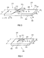
- Fig. 3 shows a further embodiment of the suction belt 200 having a different configuration of the second areas 212.
- the second area 212 is formed of two separate parts 212 1 and 212 2 each extending over only a part of the width w of the belt 200. More specifically, the first part 212 1 is arranged at a first edge 218 of the belt 200 and extends in the width direction w by a distance w 1 towards a second, opposing edge 220. The second part 212 2 extends from the second edge 220 in the width direction towards the first edge 218 by a distance w 2 . Thus, the parts 212 1 and 212 2 are arranged with a gap g there between.
- Fig. 4 shows yet another embodiment of the suction belt 200 in accordance with which the second area is arranged at a distance from the edges 218 and 220 of the belt 200.
- the second area 212 has a width w 1 and may be arranged at the center of the belt 200. However, also an eccentric arrangement may be desired.
- the second area 212 is arranged at a distance g 1 from the first edge 218 and at a distance g 2 from the second edge 220, wherein the distances g 1 and g 2 may be the same or may be different.
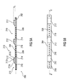
- Fig. 5(a) shows a sectional view of a suction belt in accordance with another embodiment taken along a line a-a' shown in Fig. 5(b) which is a top view of the belt.
- the entire first area 210 comprises the holes 208, i.e. there is no area 210 2 .
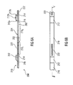
- Fig. 6(a) shows a sectional view of a suction belt in accordance with yet another embodiment taken along a line a-a' shown in Fig. 6(b) which is a top view of the belt.
- a longitudinal slot or slit 222 is formed that extends from the bottom side 202 to the top side 204.
- the second area 212 has a first linearly upward extending part 212a (see Fig. 5(a) ), a second, horizontal part 212b, and a third, vertical part 212c.
- a ramp-shaped part or elevation instead of such a ramp-shaped part or elevation, also other shapes may be used.
- Fig. 7(a) shows the second area 212 comprising a first part 212a that starts to rise or ascend from the second transition 216 upwards in a curved or bend shape until it reaches the second, horizontal part 212b.
- a third, vertical part 212c follows.
- Fig. 7(b) shows a further embodiment having a first part 212a linearly extending upward from the second transition 216 to the first transition 214, where the vertical part 212c follows. This ramp does not have a horizontal part 212b.
- a curved part may be used.
- Fig. 7(c) shows yet another embodiment of the second area 212 having a curved surface 212d.
- FIG. 8 Another embodiment of the suction belt will now described with reference to Fig. 8 in which the second areas 212 comprise a first, vertical part 212a extending upwardly at the second transition 216, a horizontal part 212b followed by a second vertical part 212c at the first transition 214. Further, from the embodiment of Fig. 8 it is clear that the suction belt is not limited to openings having the shape of holes 208 or slits 222, rather, a plurality of slits 222 may be provided.
- Fig. 8(b) is a top view of the belt 200 and the sectional view of Fig. 8(a) is taken along lines a-a'.
- holes and slits may be used for realizing the openings for applying a suction force.
- holes or silts arranged side by side in the width direction may be provided.
- Fig. 9 shows another embodiment of the suction belt in accordance with which the first area 210 has a top side that rises starting from the first transition 214 to the second transition 216 up to the height of the second area 212.
- the top side of the second area 210 may rise to a first height below the height of the second area. After a horizontal part the top side starts to rise again.
- Fig. 11 shows a suction conveyer 300 comprising a vacuum means having a vacuum chamber 302 and a vacuum pump 304. Further, a first roller 306 and a second roller 308 driven by a motor 310 are provided.
- a suction belt 200 in accordance with embodiments of the invention extends around the two rollers 306 and 308, and the vacuum chamber 302 applies a suction force to the openings 208 of the suction belt 200 for holding an object transported by the belt 200.
- Fig. 12 shows a schematic view of a section of an inserter 400 comprising the suction conveyor 300 of Fig. 11 for transporting an envelope or cover along an inserting or filling path.
- the suction conveyor 300 comprises a suction belt 200 in accordance with embodiments of the invention.
- the inserter 400 further comprises a goods transport 402 comprising a belt or a chain 404 extending around respective rollers (not shown).
- One or more pushers 406 are mounted to the belt 404.
- the pushers 406 are provided for engaging with a trailing edge 408 of an object 410 to be inserted into an envelope 412 moved by the suction conveyor 300.
- the suction conveyor 300 moves the envelope 412 with a velocity that is slower than the velocity of the goods transport 402 so that along the inserting or filling path the object 410 will eventually be inserted into the envelope 412.
- the inserter 400 further comprises air nozzles 414a, 414b which blow air towards the envelope 412 for opening it.
- a separating device 416 is provided which comprises a belt or chain 418 arranged above the suction conveyor 300 and extending around two roller (of which only one roller 420 is shown in Fig. 12 ).
- One or more separating elements 422 are mounted to the belt 418 and are provided to engage with a trailing edge 412a of a first side 412b of the envelope 412 and to maintain the first side 412b separated from a second side 412c of the envelope 412.
- the separating element 414 is moved together with the envelope 412 so that the separation is maintained over at least a part of the filling path (e.g. at least until a leading edge of the object 410 is arranged inside the envelope 412).
- the envelope 412 is arranged on the suction belt 200 in its first area 210 with its second side 412c in contact with the suction belt 200, more specifically, a part of the second side 412c of the envelope 412 is arranged on the second part 210 2 having no holes. Another part of the second side 412c to which an envelope flap 412d is arranged on the first part 210 1 of the belt 200 having the holes. As can be seen, the envelope 412 is placed on the suction belt 200 such that a trailing edge of the flap 412d is arranged at the transition 214.
- the thickness of the suction belt 200 in the second area 212 is such that the distance d 3 (see Fig.
- the distance d 3 is less than a maximum opening of an envelope throat 412e during the filling process.
- the height d 3 is selected such that the object 410 is raised from the transport level of the envelope 412 so that it securely passes the flap 412d on its way into the envelope.
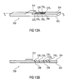
- Fig. 13 shows a suction belt in accordance with further embodiments of the invention, wherein Fig. 13(a) is an isometric view of a part of the belt, and Fig. 13(b) is a sectional view along the line b-b' in Fig. 13(a) .
- the suction belt 200 comprises the holes 208 extending from the bottom side 202 of the suction belt 200 to its top side 204.
- the top side 204 comprises shallow portions 230 1 to 230 5 , e.g. shallow recesses or shallow cups.
- small shallow recesses are provided having a width along the width direction of the belt 200 and a length along the longitudinal direction of the belt 200, wherein the width is greater than the length, see e.g. recesses 230 1 , 230 3 , 230 4 , and 230 5 .
- large recesses are provided having a length greater than a width, see e.g. recesses 230 2 .
- the belt 200 comprises only small recesses, only large recesses or both small and large recesses.
- the holes 208 extend from the bottom side to the recesses.
- a shallow recess may have a diameter that is larger than a diameter of a hole 208 connected thereto.
- One or more holes may be provided at the center of the recess or at another part of the recess.
- the suction area is greater than the diameter of the hole.
- the suction area is defined by the recess formed in the top side of the belt. It is noted that Fig. 13 shows that each recess is provided with one hole. However, other embodiments may comprise at least one recess including two or more holes.
- a combination of one large recess and a plurality of small recesses is used, wherein the large recess 230 2 is provided for applying a suction force greater than normal to the envelope flap, and which is greater than a suction force provided by a small recess.
- the large recess 230 2 is provided close to the first transition 214, preferably with one small recess 230 1 between the large recess 230 2 and the transition 214.
- the large recess 230 2 and the transition 214 may be provided between the large recess 230 2 and the transition 214.
- no small recesses may be provided between the large recess 230 2 and the transition 214, i.e., the large recess is arranged at a distance from the transition 214 that may be set dependent from the dimension of the envelopes to be handled.
Landscapes
- Engineering & Computer Science (AREA)
- Mechanical Engineering (AREA)
- Supplying Of Containers To The Packaging Station (AREA)
- Container Filling Or Packaging Operations (AREA)
- Delivering By Means Of Belts And Rollers (AREA)
- Packaging Of Special Articles (AREA)
- Collation Of Sheets And Webs (AREA)
- Auxiliary Devices For And Details Of Packaging Control (AREA)
- Sealing Of Jars (AREA)
- Manipulator (AREA)
- Belt Conveyors (AREA)
Claims (13)
- Ein Saugband (200) zum Befördern eines Umschlags (412), der eine Umschlagsvorderseite (412c), eine Umschlagsrückseite (412b) und eine Umschlagslasche (212d) auf der Umschlagsvorderseite aufweist, wobei das Saugband folgende Merkmale aufweist:einen ersten Bereich (210), der dazu konfiguriert ist, ein Ausüben einer Saugkraft auf zumindest einen Teil des Umschlags zu ermöglichen; undeinen zweiten Bereich (212), der neben dem ersten Bereich (210) angeordnet ist,wobei eine Dicke des Saugbandes (200) an einem Übergang (214) von dem ersten Bereich (210) zu dem zweiten Bereich (212) wechselt,dadurch gekennzeichnet, dassder Umschlag (412) derart auf dem Saugband (200) angeordnet ist, dass seine Umschlagslasche (412d) auf dem neben dem zweiten Bereich (212) befindlichen ersten Bereich (210) angeordnet ist, so dass während eines Füllvorgangs ein oder mehrere Güter, die in den Umschlag (412) einzufügen sind, den zweiten Bereich (212) passieren, ohne mit der Umschlagslasche (412d) zu kollidieren.
- Das Saugband (200) gemäß Anspruch 1, das eine Oberseite (204) und eine Unterseite (202) aufweist, wobei die Oberseite (2041) des ersten Bereichs (210) zumindest teilweise unter der Oberseite (2042) des zweiten Bereichs (212) liegt.
- Das Saugband (200) gemäß Anspruch 1 oder 2, bei dem der zweite Bereich (212) einen ersten, nach oben ansteigenden Teilabschnitt (212a), einen zweiten, horizontalen Teilabschnitt (212b) und einen dritten, vertikalen Teilabschnitt (212c) aufweist.
- Das Saugband (200) gemäß Anspruch 1 oder 2, bei dem der zweite Bereich (212) einen ersten, nach oben ansteigenden Teilabschnitt (212a) und einen zweiten, vertikalen Teilabschnitt (212c) aufweist.
- Das Saugband (200) gemäß einem der Ansprüche 1 bis 4, bei dem der erste Bereich (210) eine oder mehrere Öffnungen (208, 222) aufweist, die sich von einer Unterseite (202) des Saugbandes (200) zu einer Oberseite (204) des Saugbandes (200) erstrecken, wobei durch die eine oder die mehreren Öffnungen (208, 222) eine Saugkraft auf den auf dem ersten Bereich (210) angeordneten Umschlag ausgeübt werden kann.
- Das Saugband (200) gemäß einem der Ansprüche 1 bis 5, bei dem zumindest zwei erste Bereiche (210) und zumindest zwei zweite Bereiche (212) abwechselnd entlang der Längsrichtung des Saugbandes (200) angeordnet sind.
- Das Saugband (200) gemäß einem der Ansprüche 1 bis 6, bei dem der Umschlag (412) während des Füllvorgangs bewegt wird oder bei dem der Umschlag (412) während des Füllvorgangs angehalten wird.
- Das Saugband (200) gemäß einem der Ansprüche 1 bis 7, bei dem der Übergang zwischen dem ersten Bereich (210) und dem zweiten Bereich (212) eine Stufe oder einen Absatz aufweist.
- Das Saugband (200) gemäß einem der Ansprüche 1 bis 8, das eine oder mehrere flache Aussparungen (2301-2305) aufweist, die in der Oberseite (204) des Saugbandes (200) gebildet sind, wobei sich die jeweiligen Öffnungen (208) von der Unterseite (202) des Saugbandes (200) bis zu den jeweiligen Aussparungen (2301-2305) erstrecken.
- Das Saugband (200) gemäß Anspruch 9, bei dem die flache Aussparung (2301-2305) größer ist als ein Durchmesser eines oder mehrerer Löcher (208), die durch die Aussparung verbunden sind.
- Das Saugband (200) gemäß Anspruch 9 oder 10, bei dem die eine oder die mehreren flachen Aussparungen (2301-2305) kleine und/oder große Aussparungen aufweisen, wobei eine kleine Aussparung (2301, 2303-2305) eine Breite entlang der Breitenrichtung des Saugbandes (200) aufweist, die größer ist als eine Länge entlang der Längsrichtung des Saugbandes (200), und wobei eine große Aussparung (2302) eine Länge entlang der Längsrichtung des Saugbandes (200) aufweist, die größer ist als eine Breite entlang der Breitenrichtung des Saugbandes (200).
- Das Saugband (200) gemäß Anspruch 11, das eine große Aussparung (2302) aufweist, die neben dem Übergang (214) von dem ersten Bereich (210) zu dem zweiten Bereich (212) angeordnet ist, wobei zwischen dem Übergang (214) und der großen Aussparung (2302) eine kleine Aussparung (2301) angeordnet ist.
- Eine Saugfördereinrichtung (300), die folgende Merkmale aufweist:eine Vakuumeinrichtung (302, 304),eine erste, angetriebene Rolle (308),eine zweite Rolle (306), undein Saugband (200) gemäß einem der Ansprüche 1 bis 12, das sich um die erste Rolle (308) und um die zweite Rolle (306) herum erstreckt,wobei die Vakuumeinrichtung (302, 304) dazu angeordnet ist, eine Saugkraft bereitzustellen, die auf den Umschlag (412), der auf dem ersten Bereich (210) des Saugbandes (200) angeordnet ist, ausgeübt werden soll.
Priority Applications (1)
| Application Number | Priority Date | Filing Date | Title |
|---|---|---|---|
| EP11718097A EP2432648B1 (de) | 2010-05-07 | 2011-05-06 | Absaugband |
Applications Claiming Priority (4)
| Application Number | Priority Date | Filing Date | Title |
|---|---|---|---|
| US33233810P | 2010-05-07 | 2010-05-07 | |
| EP10162320 | 2010-05-07 | ||
| PCT/EP2011/057318 WO2011138439A2 (en) | 2010-05-07 | 2011-05-06 | Suction belt |
| EP11718097A EP2432648B1 (de) | 2010-05-07 | 2011-05-06 | Absaugband |
Publications (2)
| Publication Number | Publication Date |
|---|---|
| EP2432648A2 EP2432648A2 (de) | 2012-03-28 |
| EP2432648B1 true EP2432648B1 (de) | 2013-03-27 |
Family
ID=44119006
Family Applications (6)
| Application Number | Title | Priority Date | Filing Date |
|---|---|---|---|
| EP11718097A Active EP2432648B1 (de) | 2010-05-07 | 2011-05-06 | Absaugband |
| EP11718386.3A Active EP2566707B1 (de) | 2010-05-07 | 2011-05-06 | Vorrichtung und verfahren zum einfügen von einer oder mehreren waren in eine bewegliche abdeckung |
| EP11718100.8A Active EP2566706B1 (de) | 2010-05-07 | 2011-05-06 | Vorrichtung und verfahren zum einfügen von einer oder mehreren waren in eine bewegliche abdeckung |
| EP11733596.8A Active EP2566709B1 (de) | 2010-05-07 | 2011-05-06 | Vorrichtung und verfahren zum einfügen von einer oder mehreren waren in eine bewegliche abdeckung |
| EP12194672.7A Active EP2572894B1 (de) | 2010-05-07 | 2011-05-06 | Vorrichtung und Verfahren zum Einfügen von einer oder mehreren Waren in ein bewegliches Kuvert |
| EP11722357.8A Active EP2566708B1 (de) | 2010-05-07 | 2011-05-06 | Vorrichtung und verfahren zum einfügen von einer oder mehreren waren in eine bewegliche abdeckung |
Family Applications After (5)
| Application Number | Title | Priority Date | Filing Date |
|---|---|---|---|
| EP11718386.3A Active EP2566707B1 (de) | 2010-05-07 | 2011-05-06 | Vorrichtung und verfahren zum einfügen von einer oder mehreren waren in eine bewegliche abdeckung |
| EP11718100.8A Active EP2566706B1 (de) | 2010-05-07 | 2011-05-06 | Vorrichtung und verfahren zum einfügen von einer oder mehreren waren in eine bewegliche abdeckung |
| EP11733596.8A Active EP2566709B1 (de) | 2010-05-07 | 2011-05-06 | Vorrichtung und verfahren zum einfügen von einer oder mehreren waren in eine bewegliche abdeckung |
| EP12194672.7A Active EP2572894B1 (de) | 2010-05-07 | 2011-05-06 | Vorrichtung und Verfahren zum Einfügen von einer oder mehreren Waren in ein bewegliches Kuvert |
| EP11722357.8A Active EP2566708B1 (de) | 2010-05-07 | 2011-05-06 | Vorrichtung und verfahren zum einfügen von einer oder mehreren waren in eine bewegliche abdeckung |
Country Status (5)
| Country | Link |
|---|---|
| US (6) | US20120168280A1 (de) |
| EP (6) | EP2432648B1 (de) |
| JP (1) | JP5778760B2 (de) |
| CN (2) | CN103025539A (de) |
| WO (5) | WO2011138439A2 (de) |
Families Citing this family (22)
| Publication number | Priority date | Publication date | Assignee | Title |
|---|---|---|---|---|
| DE3870903D1 (de) * | 1987-02-04 | 1992-06-17 | Emsens Antoine Sarl | Maschine zur automatischen herstellung von fleisch- und/oder gemuesespiessen. |
| US20130019571A1 (en) * | 2011-07-20 | 2013-01-24 | OYSTAR North America | Methods and apparatus for high-speed pouch-filling |
| DE102011122235A1 (de) * | 2011-12-23 | 2013-06-27 | Winkler + Dünnebier Gmbh | Verfahren und Vereinigungseinheit zur Vereinigung von zu verpackendem Gut und einem Verpackungsrohling |
| DE102012207286B4 (de) | 2012-05-02 | 2025-11-06 | Böwe Systec Gmbh | Verfahren zum einstellen zumindest einer einrichtung einer kuvertiervorrichtung und kuvertiervorrichtung |
| EP3296237B1 (de) * | 2012-10-03 | 2019-05-29 | Amazon Technologies, Inc. | Funktionelle schalen zur handhabung von produkten in einer fördertechnikanlage |
| EP2746060B1 (de) | 2012-12-20 | 2016-04-27 | BÖWE SYSTEC GmbH | Kuvertierer und Verfahren zum Öffnen eines Kuvertmunds eines entlang eines Kuvertkanals transportierten Kuverts |
| CN103979151B (zh) * | 2014-05-23 | 2016-06-15 | 江南大学 | 自动装袋包装机 |
| CH710033A2 (de) * | 2014-08-28 | 2016-02-29 | Kern Ag | Packtasche. |
| US10315457B2 (en) * | 2015-02-20 | 2019-06-11 | Dmt Solutions Global Corporation | Envelope inserter with suction cup opening mechanism and improved insertion motion control |
| US20160243884A1 (en) * | 2015-02-20 | 2016-08-25 | Pitney Bowes Inc. | Method of controlling insertion depth of a moving collation into an accelerating envelope |
| MX2018005870A (es) * | 2015-11-10 | 2018-08-15 | Cryovac Inc | Aparato y proceso para la evacuacion de paquetes. |
| WO2017184326A1 (en) * | 2016-04-20 | 2017-10-26 | The Procter & Gamble Company | Apparatuses and methods for folding absorbent articles |
| EP3554970B1 (de) * | 2016-12-16 | 2024-10-23 | Kimberly-Clark Worldwide, Inc. | Vakuumnasenrolle |
| CN107187252B (zh) * | 2017-07-05 | 2019-02-22 | 前海拉斯曼智能系统(深圳)有限公司 | 装信封机构 |
| EP3486079B1 (de) * | 2017-11-16 | 2021-02-24 | EMMECI S.p.A. | Linie zur herstellung von abgedeckten kartons |
| CN108454949A (zh) * | 2018-05-11 | 2018-08-28 | 天津树达科技发展有限公司 | 包装生产线用打包转向设备 |
| CN109808344A (zh) * | 2019-02-21 | 2019-05-28 | 华东师范大学 | 一种水循环的超声波毛笔清洗笔架 |
| CN113716136A (zh) * | 2020-05-25 | 2021-11-30 | 中山市力龙机械有限公司 | 一种压模机构及一种全自动包装机 |
| US12129145B2 (en) * | 2021-05-27 | 2024-10-29 | Ricoh Company, Ltd. | Enclosing apparatus and image forming system |
| JP7668723B2 (ja) | 2021-10-08 | 2025-04-25 | 倉敷化工株式会社 | 防振装置の製造方法 |
| US12617226B1 (en) * | 2022-09-29 | 2026-05-05 | Cenveo Worldwide Limited | Robotic envelope separator |
| DE102023123942A1 (de) | 2023-09-06 | 2025-03-06 | Canon Production Printing Holding B.V. | Vorrichtung und Verfahren zum Ausüben einer Streckung auf einen Aufzeichnungsträger |
Citations (1)
| Publication number | Priority date | Publication date | Assignee | Title |
|---|---|---|---|---|
| GB2264279A (en) * | 1992-02-20 | 1993-08-25 | Bertelsmann Distribution Gmbh | Inserting items into folders. |
Family Cites Families (55)
| Publication number | Priority date | Publication date | Assignee | Title |
|---|---|---|---|---|
| US2771726A (en) * | 1953-09-10 | 1956-11-27 | Pitney Bowes Inc | Sheet handling and envelope stuffing machine |
| US3423900A (en) * | 1965-01-18 | 1969-01-28 | Bell & Howell Co | Collating-inserting machine |
| GB1340890A (en) * | 1970-10-29 | 1973-12-19 | Dickinson Co Ltd John | Envelopes for use with automatic inserting and closing machines |
| US3861669A (en) * | 1972-06-15 | 1975-01-21 | Tokyo Shibaura Electric Co | Apparatus for feeding sheet-like articles from a stack of articles |
| US3858381A (en) | 1973-07-18 | 1975-01-07 | Xerox Corp | Envelope stuffing apparatus |
| US4079576A (en) * | 1975-04-21 | 1978-03-21 | Bell & Howell Company | In-line inserter |
| US4020615A (en) * | 1975-12-15 | 1977-05-03 | Pitney-Bowes, Inc. | Envelope inserter and feeder system |
| US4479573A (en) * | 1980-04-07 | 1984-10-30 | R. W. Hartnett Company | Gauging assembly for capsule orienting and turning apparatus |
| US4739606A (en) * | 1982-06-10 | 1988-04-26 | Hammermill Paper Company | Conveyor means of system for in-line processing of envelopes and the like |
| US4525986A (en) | 1982-09-28 | 1985-07-02 | Noll Marvin H | Apparatus and process for inserting inserts into envelopes |
| DE3312087A1 (de) * | 1983-04-02 | 1984-10-04 | Winkler & Dünnebier, Maschinenfabrik und Eisengießerei GmbH & Co KG, 5450 Neuwied | Verfahren und vorrichtung zum einfuellen von fuellgut in eine huelle |
| US4637602A (en) * | 1985-12-09 | 1987-01-20 | Pitney Bowes Inc. | Document guide apparatus for preventing jams |
| US4817368A (en) | 1986-10-14 | 1989-04-04 | J.A.D. Enterprises, Inc. | Mail inserting and collating apparatus |
| JPH0446039A (ja) | 1990-06-13 | 1992-02-17 | Ricoh Co Ltd | くもり濃度調節機能付くもりガラス装置 |
| JP2518433Y2 (ja) * | 1990-08-23 | 1996-11-27 | シャープ株式会社 | 転写紙搬送装置 |
| US5255498A (en) * | 1990-11-02 | 1993-10-26 | Pitney Bowes Inc. | Envelope stuffing apparatus |
| US5082255A (en) * | 1990-12-14 | 1992-01-21 | Pitney Bowes Inc. | Sheet processing apparatus |
| JPH05107968A (ja) * | 1991-10-16 | 1993-04-30 | Fuji Xerox Co Ltd | 画像形成装置の用紙搬送装置 |
| US5168689A (en) * | 1991-10-24 | 1992-12-08 | Pitney Bowes Inc. | Envelope stuffing apparatus with adjustable deck for handling different styled envelopes |
| CA2091733C (en) * | 1992-03-30 | 2005-03-15 | Jack Cohen | Envelope stuffing device |
| US5430990A (en) | 1992-09-18 | 1995-07-11 | Long John A | Envelope stuffing apparatus |
| JP2897801B2 (ja) * | 1993-03-18 | 1999-05-31 | シオノギクオリカプス株式会社 | 直径に比べて小さい厚みをもつ円板状固形製剤の搬送装置 |
| US5247780A (en) * | 1993-03-29 | 1993-09-28 | Pitney Bowes Inc. | Rotating envelope opening finger |
| JPH09504744A (ja) | 1993-05-21 | 1997-05-13 | ロングフォード イクィップメント インターナショナル リミテッド | 封筒詰め装置 |
| US5447015A (en) * | 1993-11-01 | 1995-09-05 | Pitney Bowes Inc. | High speed insertion device |
| US5374044A (en) * | 1993-11-01 | 1994-12-20 | Pitney Bowes Inc. | Vacuum drum document handling system for an insertion device |
| US5428944A (en) * | 1993-11-01 | 1995-07-04 | Pitney Bowes Inc. | Envelope transport, deskew and stop apparatus |
| DE9317366U1 (de) * | 1993-11-12 | 1994-12-01 | Böwe Systec AG, 86161 Augsburg | Kuvertiervorrichtung |
| US5675959A (en) * | 1996-01-18 | 1997-10-14 | Pitney Bowes Inc. | Opening fingers for envelope inserting apparatus |
| US6134865A (en) * | 1998-02-23 | 2000-10-24 | Longford Equipment International Limited | Paper stack handler |
| GB9805902D0 (en) * | 1998-03-19 | 1998-05-13 | Pitney Bowes Ltd | Envelope opening apparatus |
| US6718740B2 (en) * | 1998-09-24 | 2004-04-13 | Bell & Howell Mail And Messaging Technologies Company | Inserting apparatus and method with controlled, master cycle speed-dependent actuator operations |
| US6164046A (en) * | 1999-02-16 | 2000-12-26 | Todd C. Werner | High speed machine for inserting sheets into envelopes |
| US6494019B1 (en) * | 2000-02-22 | 2002-12-17 | Jeffrey A. Lingle | High speed envelope inserter |
| PL358453A1 (en) * | 2000-05-17 | 2004-08-09 | Todd C. Werner | High speed machine for inserting sheets into envelopes |
| JP2002103598A (ja) * | 2000-07-26 | 2002-04-09 | Olympus Optical Co Ltd | プリンタ |
| JP3690257B2 (ja) * | 2000-08-28 | 2005-08-31 | 株式会社村田製作所 | チップ部品の搬送装置 |
| JP2002137840A (ja) * | 2000-11-02 | 2002-05-14 | Hokushin Ind Inc | 紙葉類搬送用無端ベルト |
| ITBO20010031A1 (it) * | 2001-01-24 | 2002-07-24 | Cmc Spa | Macchina imbustatrice |
| CA2448115A1 (en) | 2001-05-21 | 2002-12-05 | Rodney Ian Rawlinson | A mail insertion method and apparatus |
| WO2003012486A2 (en) | 2001-08-02 | 2003-02-13 | Jonathan Gerlitz | Non-invasive glucose-meter |
| ITBO20020070A1 (it) * | 2002-02-08 | 2003-08-08 | Cmc Spa | Macchina imbustatrice |
| US6746007B2 (en) * | 2002-10-25 | 2004-06-08 | Pitney Bowes Inc. | Method and apparatus for controlling enclosure material feeding in a mail inserting system |
| US6755411B2 (en) * | 2002-10-25 | 2004-06-29 | Pitney Bowes Inc. | Envelope transport module with vacuum ports for use in an envelope inserting machine |
| EP2433811B1 (de) | 2003-04-14 | 2014-01-29 | Bell and Howell, LLC | Kuvertier- und Transportmaschine für Umschläge |
| ITMI20031794A1 (it) * | 2003-09-19 | 2005-03-20 | Sitma Spa | Dispositivo per l'imbustamento automatico di prodotti. |
| JP4447518B2 (ja) * | 2005-06-28 | 2010-04-07 | リコーエレメックス株式会社 | 用紙後処理装置 |
| US7398635B2 (en) * | 2006-01-11 | 2008-07-15 | Pitney Bowes Inc. | Method and device for aligning a receiving envelope in a mail inserter |
| WO2008006392A1 (en) * | 2006-07-12 | 2008-01-17 | Buhrs-Itm Gmbh | Inserting apparatus and method for placing a product in an envelope using such an inserting apparatus |
| US8037992B2 (en) * | 2006-08-22 | 2011-10-18 | Ackley Machine Corp. | Method and apparatus for transporting and processing on-edge tablets |
| US7454882B2 (en) * | 2006-10-12 | 2008-11-25 | Bowe Bell + Howell Company | Methods for variably opening envelopes |
| GB2462294A (en) * | 2008-07-31 | 2010-02-03 | Neopost Technologies | Apparatus for inserting a contents pack into an envelope |
| US7971865B2 (en) * | 2008-09-05 | 2011-07-05 | Kern International, Inc. | Inserting apparatus for discrete objects into envelopes and related methods |
| EP2243637B1 (de) * | 2009-04-24 | 2014-05-21 | Neopost Technologies | Kuvertiervorrichtung |
| GB2470955A (en) * | 2009-06-12 | 2010-12-15 | Neopost Technologies | Document inserting apparatus |
-
2011
- 2011-05-06 WO PCT/EP2011/057318 patent/WO2011138439A2/en not_active Ceased
- 2011-05-06 EP EP11718097A patent/EP2432648B1/de active Active
- 2011-05-06 EP EP11718386.3A patent/EP2566707B1/de active Active
- 2011-05-06 WO PCT/EP2011/057323 patent/WO2011138440A2/en not_active Ceased
- 2011-05-06 WO PCT/EP2011/057336 patent/WO2011138446A2/en not_active Ceased
- 2011-05-06 EP EP11718100.8A patent/EP2566706B1/de active Active
- 2011-05-06 EP EP11733596.8A patent/EP2566709B1/de active Active
- 2011-05-06 JP JP2013509521A patent/JP5778760B2/ja active Active
- 2011-05-06 EP EP12194672.7A patent/EP2572894B1/de active Active
- 2011-05-06 WO PCT/EP2011/057338 patent/WO2011138447A1/en not_active Ceased
- 2011-05-06 WO PCT/EP2011/057331 patent/WO2011138443A1/en not_active Ceased
- 2011-05-06 EP EP11722357.8A patent/EP2566708B1/de active Active
- 2011-05-06 CN CN2011800337274A patent/CN103025539A/zh active Pending
- 2011-05-06 CN CN201180033709.6A patent/CN103025538B/zh active Active
-
2012
- 2012-01-17 US US13/351,683 patent/US20120168280A1/en not_active Abandoned
- 2012-11-05 US US13/669,133 patent/US9567122B2/en active Active
- 2012-11-06 US US13/669,865 patent/US20130152514A1/en not_active Abandoned
- 2012-11-06 US US13/669,904 patent/US10173798B2/en active Active
- 2012-11-06 US US13/669,917 patent/US9359095B2/en active Active
- 2012-11-06 US US13/669,889 patent/US9493259B2/en active Active
Patent Citations (1)
| Publication number | Priority date | Publication date | Assignee | Title |
|---|---|---|---|---|
| GB2264279A (en) * | 1992-02-20 | 1993-08-25 | Bertelsmann Distribution Gmbh | Inserting items into folders. |
Also Published As
Similar Documents
| Publication | Publication Date | Title |
|---|---|---|
| US20120168280A1 (en) | Suction belt | |
| JP5495024B2 (ja) | 給紙装置及び画像形成装置 | |
| JP3223938U (ja) | シート用の搬送ベルトを備える印刷機 | |
| CA2482167A1 (en) | Device for processing stacks of electrostatically chargeable flat items | |
| CN103895367A (zh) | 输送装置及图像形成装置 | |
| JP5090614B2 (ja) | シートを処理する機械、特に印刷機にシートを案内する方法および装置 | |
| CN101823374A (zh) | 记录纸传送路结构及打印机 | |
| CN111204600A (zh) | 介质供给装置 | |
| JP2788382B2 (ja) | 給紙装置 | |
| JP2021059417A (ja) | 搬送装置 | |
| JPS63165239A (ja) | 後部エアナイフを備えた上側真空波形シート給送装置 | |
| JP2738920B2 (ja) | シートスタッカ | |
| US5181711A (en) | Device for discharging sheets from the bottom of a stack | |
| CN111204601B (zh) | 介质供给装置 | |
| JP2019155718A (ja) | 製袋機における把手取付装置 | |
| US8424866B2 (en) | Sheet feeding apparatus and image forming apparatus | |
| JP2001031272A (ja) | 給紙装置 | |
| JPH04358637A (ja) | 画像形成装置の給紙装置 | |
| JP3875363B2 (ja) | スタッカ装置 | |
| JP2003095467A (ja) | エア給紙装置、および画像形成装置 | |
| JPS6216944A (ja) | 給紙装置 | |
| JP2007031154A (ja) | 印刷枚葉紙を丁合いする方法および装置 | |
| JP2006016159A (ja) | エアー吸着方式給紙装置 | |
| JP2010168150A (ja) | 紙受け装置における紙受け処理方法 | |
| JP2005239311A (ja) | 給紙装置 |
Legal Events
| Date | Code | Title | Description |
|---|---|---|---|
| PUAI | Public reference made under article 153(3) epc to a published international application that has entered the european phase |
Free format text: ORIGINAL CODE: 0009012 |
|
| 17P | Request for examination filed |
Effective date: 20111221 |
|
| AK | Designated contracting states |
Kind code of ref document: A2 Designated state(s): AL AT BE BG CH CY CZ DE DK EE ES FI FR GB GR HR HU IE IS IT LI LT LU LV MC MK MT NL NO PL PT RO RS SE SI SK SM TR |
|
| GRAP | Despatch of communication of intention to grant a patent |
Free format text: ORIGINAL CODE: EPIDOSNIGR1 |
|
| DAX | Request for extension of the european patent (deleted) | ||
| GRAS | Grant fee paid |
Free format text: ORIGINAL CODE: EPIDOSNIGR3 |
|
| GRAA | (expected) grant |
Free format text: ORIGINAL CODE: 0009210 |
|
| AK | Designated contracting states |
Kind code of ref document: B1 Designated state(s): AL AT BE BG CH CY CZ DE DK EE ES FI FR GB GR HR HU IE IS IT LI LT LU LV MC MK MT NL NO PL PT RO RS SE SI SK SM TR |
|
| REG | Reference to a national code |
Ref country code: GB Ref legal event code: FG4D |
|
| REG | Reference to a national code |
Ref country code: CH Ref legal event code: NV Representative=s name: BOVARD AG, CH Ref country code: CH Ref legal event code: EP |
|
| REG | Reference to a national code |
Ref country code: AT Ref legal event code: REF Ref document number: 603115 Country of ref document: AT Kind code of ref document: T Effective date: 20130415 |
|
| REG | Reference to a national code |
Ref country code: IE Ref legal event code: FG4D |
|
| REG | Reference to a national code |
Ref country code: DE Ref legal event code: R096 Ref document number: 602011001182 Country of ref document: DE Effective date: 20130529 |
|
| PG25 | Lapsed in a contracting state [announced via postgrant information from national office to epo] |
Ref country code: NO Free format text: LAPSE BECAUSE OF FAILURE TO SUBMIT A TRANSLATION OF THE DESCRIPTION OR TO PAY THE FEE WITHIN THE PRESCRIBED TIME-LIMIT Effective date: 20130627 Ref country code: BG Free format text: LAPSE BECAUSE OF FAILURE TO SUBMIT A TRANSLATION OF THE DESCRIPTION OR TO PAY THE FEE WITHIN THE PRESCRIBED TIME-LIMIT Effective date: 20130627 Ref country code: SE Free format text: LAPSE BECAUSE OF FAILURE TO SUBMIT A TRANSLATION OF THE DESCRIPTION OR TO PAY THE FEE WITHIN THE PRESCRIBED TIME-LIMIT Effective date: 20130327 Ref country code: LT Free format text: LAPSE BECAUSE OF FAILURE TO SUBMIT A TRANSLATION OF THE DESCRIPTION OR TO PAY THE FEE WITHIN THE PRESCRIBED TIME-LIMIT Effective date: 20130327 |
|
| REG | Reference to a national code |
Ref country code: AT Ref legal event code: MK05 Ref document number: 603115 Country of ref document: AT Kind code of ref document: T Effective date: 20130327 |
|
| REG | Reference to a national code |
Ref country code: LT Ref legal event code: MG4D |
|
| PG25 | Lapsed in a contracting state [announced via postgrant information from national office to epo] |
Ref country code: LV Free format text: LAPSE BECAUSE OF FAILURE TO SUBMIT A TRANSLATION OF THE DESCRIPTION OR TO PAY THE FEE WITHIN THE PRESCRIBED TIME-LIMIT Effective date: 20130327 Ref country code: SI Free format text: LAPSE BECAUSE OF FAILURE TO SUBMIT A TRANSLATION OF THE DESCRIPTION OR TO PAY THE FEE WITHIN THE PRESCRIBED TIME-LIMIT Effective date: 20130327 Ref country code: GR Free format text: LAPSE BECAUSE OF FAILURE TO SUBMIT A TRANSLATION OF THE DESCRIPTION OR TO PAY THE FEE WITHIN THE PRESCRIBED TIME-LIMIT Effective date: 20130628 Ref country code: FI Free format text: LAPSE BECAUSE OF FAILURE TO SUBMIT A TRANSLATION OF THE DESCRIPTION OR TO PAY THE FEE WITHIN THE PRESCRIBED TIME-LIMIT Effective date: 20130327 |
|
| REG | Reference to a national code |
Ref country code: NL Ref legal event code: VDEP Effective date: 20130327 |
|
| PG25 | Lapsed in a contracting state [announced via postgrant information from national office to epo] |
Ref country code: BE Free format text: LAPSE BECAUSE OF FAILURE TO SUBMIT A TRANSLATION OF THE DESCRIPTION OR TO PAY THE FEE WITHIN THE PRESCRIBED TIME-LIMIT Effective date: 20130327 Ref country code: HR Free format text: LAPSE BECAUSE OF FAILURE TO SUBMIT A TRANSLATION OF THE DESCRIPTION OR TO PAY THE FEE WITHIN THE PRESCRIBED TIME-LIMIT Effective date: 20130327 |
|
| PG25 | Lapsed in a contracting state [announced via postgrant information from national office to epo] |
Ref country code: IS Free format text: LAPSE BECAUSE OF FAILURE TO SUBMIT A TRANSLATION OF THE DESCRIPTION OR TO PAY THE FEE WITHIN THE PRESCRIBED TIME-LIMIT Effective date: 20130727 Ref country code: NL Free format text: LAPSE BECAUSE OF FAILURE TO SUBMIT A TRANSLATION OF THE DESCRIPTION OR TO PAY THE FEE WITHIN THE PRESCRIBED TIME-LIMIT Effective date: 20130327 Ref country code: AT Free format text: LAPSE BECAUSE OF FAILURE TO SUBMIT A TRANSLATION OF THE DESCRIPTION OR TO PAY THE FEE WITHIN THE PRESCRIBED TIME-LIMIT Effective date: 20130327 Ref country code: PT Free format text: LAPSE BECAUSE OF FAILURE TO SUBMIT A TRANSLATION OF THE DESCRIPTION OR TO PAY THE FEE WITHIN THE PRESCRIBED TIME-LIMIT Effective date: 20130729 Ref country code: EE Free format text: LAPSE BECAUSE OF FAILURE TO SUBMIT A TRANSLATION OF THE DESCRIPTION OR TO PAY THE FEE WITHIN THE PRESCRIBED TIME-LIMIT Effective date: 20130327 Ref country code: SK Free format text: LAPSE BECAUSE OF FAILURE TO SUBMIT A TRANSLATION OF THE DESCRIPTION OR TO PAY THE FEE WITHIN THE PRESCRIBED TIME-LIMIT Effective date: 20130327 Ref country code: RO Free format text: LAPSE BECAUSE OF FAILURE TO SUBMIT A TRANSLATION OF THE DESCRIPTION OR TO PAY THE FEE WITHIN THE PRESCRIBED TIME-LIMIT Effective date: 20130327 Ref country code: ES Free format text: LAPSE BECAUSE OF FAILURE TO SUBMIT A TRANSLATION OF THE DESCRIPTION OR TO PAY THE FEE WITHIN THE PRESCRIBED TIME-LIMIT Effective date: 20130708 Ref country code: CZ Free format text: LAPSE BECAUSE OF FAILURE TO SUBMIT A TRANSLATION OF THE DESCRIPTION OR TO PAY THE FEE WITHIN THE PRESCRIBED TIME-LIMIT Effective date: 20130327 |
|
| PG25 | Lapsed in a contracting state [announced via postgrant information from national office to epo] |
Ref country code: CY Free format text: LAPSE BECAUSE OF FAILURE TO SUBMIT A TRANSLATION OF THE DESCRIPTION OR TO PAY THE FEE WITHIN THE PRESCRIBED TIME-LIMIT Effective date: 20130327 Ref country code: PL Free format text: LAPSE BECAUSE OF FAILURE TO SUBMIT A TRANSLATION OF THE DESCRIPTION OR TO PAY THE FEE WITHIN THE PRESCRIBED TIME-LIMIT Effective date: 20130327 |
|
| PG25 | Lapsed in a contracting state [announced via postgrant information from national office to epo] |
Ref country code: MC Free format text: LAPSE BECAUSE OF FAILURE TO SUBMIT A TRANSLATION OF THE DESCRIPTION OR TO PAY THE FEE WITHIN THE PRESCRIBED TIME-LIMIT Effective date: 20130327 |
|
| PG25 | Lapsed in a contracting state [announced via postgrant information from national office to epo] |
Ref country code: DK Free format text: LAPSE BECAUSE OF FAILURE TO SUBMIT A TRANSLATION OF THE DESCRIPTION OR TO PAY THE FEE WITHIN THE PRESCRIBED TIME-LIMIT Effective date: 20130327 |
|
| PLBE | No opposition filed within time limit |
Free format text: ORIGINAL CODE: 0009261 |
|
| STAA | Information on the status of an ep patent application or granted ep patent |
Free format text: STATUS: NO OPPOSITION FILED WITHIN TIME LIMIT |
|
| REG | Reference to a national code |
Ref country code: IE Ref legal event code: MM4A |
|
| 26N | No opposition filed |
Effective date: 20140103 |
|
| REG | Reference to a national code |
Ref country code: DE Ref legal event code: R097 Ref document number: 602011001182 Country of ref document: DE Effective date: 20140103 |
|
| PG25 | Lapsed in a contracting state [announced via postgrant information from national office to epo] |
Ref country code: IE Free format text: LAPSE BECAUSE OF NON-PAYMENT OF DUE FEES Effective date: 20130506 |
|
| PG25 | Lapsed in a contracting state [announced via postgrant information from national office to epo] |
Ref country code: MT Free format text: LAPSE BECAUSE OF FAILURE TO SUBMIT A TRANSLATION OF THE DESCRIPTION OR TO PAY THE FEE WITHIN THE PRESCRIBED TIME-LIMIT Effective date: 20130327 |
|
| PG25 | Lapsed in a contracting state [announced via postgrant information from national office to epo] |
Ref country code: SM Free format text: LAPSE BECAUSE OF FAILURE TO SUBMIT A TRANSLATION OF THE DESCRIPTION OR TO PAY THE FEE WITHIN THE PRESCRIBED TIME-LIMIT Effective date: 20130327 |
|
| PG25 | Lapsed in a contracting state [announced via postgrant information from national office to epo] |
Ref country code: TR Free format text: LAPSE BECAUSE OF FAILURE TO SUBMIT A TRANSLATION OF THE DESCRIPTION OR TO PAY THE FEE WITHIN THE PRESCRIBED TIME-LIMIT Effective date: 20130327 |
|
| PG25 | Lapsed in a contracting state [announced via postgrant information from national office to epo] |
Ref country code: LU Free format text: LAPSE BECAUSE OF NON-PAYMENT OF DUE FEES Effective date: 20130506 Ref country code: RS Free format text: LAPSE BECAUSE OF FAILURE TO SUBMIT A TRANSLATION OF THE DESCRIPTION OR TO PAY THE FEE WITHIN THE PRESCRIBED TIME-LIMIT Effective date: 20130627 Ref country code: HU Free format text: LAPSE BECAUSE OF FAILURE TO SUBMIT A TRANSLATION OF THE DESCRIPTION OR TO PAY THE FEE WITHIN THE PRESCRIBED TIME-LIMIT; INVALID AB INITIO Effective date: 20110506 Ref country code: MK Free format text: LAPSE BECAUSE OF FAILURE TO SUBMIT A TRANSLATION OF THE DESCRIPTION OR TO PAY THE FEE WITHIN THE PRESCRIBED TIME-LIMIT Effective date: 20130327 |
|
| REG | Reference to a national code |
Ref country code: FR Ref legal event code: PLFP Year of fee payment: 6 |
|
| REG | Reference to a national code |
Ref country code: FR Ref legal event code: PLFP Year of fee payment: 7 |
|
| REG | Reference to a national code |
Ref country code: FR Ref legal event code: PLFP Year of fee payment: 8 |
|
| PG25 | Lapsed in a contracting state [announced via postgrant information from national office to epo] |
Ref country code: AL Free format text: LAPSE BECAUSE OF FAILURE TO SUBMIT A TRANSLATION OF THE DESCRIPTION OR TO PAY THE FEE WITHIN THE PRESCRIBED TIME-LIMIT Effective date: 20130327 |
|
| P01 | Opt-out of the competence of the unified patent court (upc) registered |
Effective date: 20230527 |
|
| PGFP | Annual fee paid to national office [announced via postgrant information from national office to epo] |
Ref country code: DE Payment date: 20250521 Year of fee payment: 15 |
|
| PGFP | Annual fee paid to national office [announced via postgrant information from national office to epo] |
Ref country code: GB Payment date: 20250526 Year of fee payment: 15 |
|
| PGFP | Annual fee paid to national office [announced via postgrant information from national office to epo] |
Ref country code: IT Payment date: 20250527 Year of fee payment: 15 |
|
| PGFP | Annual fee paid to national office [announced via postgrant information from national office to epo] |
Ref country code: FR Payment date: 20250528 Year of fee payment: 15 |
|
| PGFP | Annual fee paid to national office [announced via postgrant information from national office to epo] |
Ref country code: CH Payment date: 20250601 Year of fee payment: 15 |