EP2409610B1 - Kaffeebohnenverpackungsvorrichtung und Kaffeegetränksystem damit - Google Patents
Kaffeebohnenverpackungsvorrichtung und Kaffeegetränksystem damit Download PDFInfo
- Publication number
- EP2409610B1 EP2409610B1 EP11154834.3A EP11154834A EP2409610B1 EP 2409610 B1 EP2409610 B1 EP 2409610B1 EP 11154834 A EP11154834 A EP 11154834A EP 2409610 B1 EP2409610 B1 EP 2409610B1
- Authority
- EP
- European Patent Office
- Prior art keywords
- cartridge
- coffee
- drive shaft
- coffee beans
- transportation means
- Prior art date
- Legal status (The legal status is an assumption and is not a legal conclusion. Google has not performed a legal analysis and makes no representation as to the accuracy of the status listed.)
- Not-in-force
Links
Images


Classifications
-
- A—HUMAN NECESSITIES
- A47—FURNITURE; DOMESTIC ARTICLES OR APPLIANCES; COFFEE MILLS; SPICE MILLS; SUCTION CLEANERS IN GENERAL
- A47J—KITCHEN EQUIPMENT; COFFEE MILLS; SPICE MILLS; APPARATUS FOR MAKING BEVERAGES
- A47J31/00—Apparatus for making beverages
- A47J31/42—Beverage-making apparatus with incorporated grinding or roasting means for coffee
-
- A—HUMAN NECESSITIES
- A47—FURNITURE; DOMESTIC ARTICLES OR APPLIANCES; COFFEE MILLS; SPICE MILLS; SUCTION CLEANERS IN GENERAL
- A47J—KITCHEN EQUIPMENT; COFFEE MILLS; SPICE MILLS; APPARATUS FOR MAKING BEVERAGES
- A47J31/00—Apparatus for making beverages
-
- A—HUMAN NECESSITIES
- A47—FURNITURE; DOMESTIC ARTICLES OR APPLIANCES; COFFEE MILLS; SPICE MILLS; SUCTION CLEANERS IN GENERAL
- A47J—KITCHEN EQUIPMENT; COFFEE MILLS; SPICE MILLS; APPARATUS FOR MAKING BEVERAGES
- A47J31/00—Apparatus for making beverages
- A47J31/40—Beverage-making apparatus with dispensing means for adding a measured quantity of ingredients, e.g. coffee, water, sugar, cocoa, milk, tea
-
- A—HUMAN NECESSITIES
- A47—FURNITURE; DOMESTIC ARTICLES OR APPLIANCES; COFFEE MILLS; SPICE MILLS; SUCTION CLEANERS IN GENERAL
- A47J—KITCHEN EQUIPMENT; COFFEE MILLS; SPICE MILLS; APPARATUS FOR MAKING BEVERAGES
- A47J31/00—Apparatus for making beverages
- A47J31/44—Parts or details or accessories of beverage-making apparatus
-
- A—HUMAN NECESSITIES
- A47—FURNITURE; DOMESTIC ARTICLES OR APPLIANCES; COFFEE MILLS; SPICE MILLS; SUCTION CLEANERS IN GENERAL
- A47J—KITCHEN EQUIPMENT; COFFEE MILLS; SPICE MILLS; APPARATUS FOR MAKING BEVERAGES
- A47J42/00—Coffee mills; Spice mills
-
- A—HUMAN NECESSITIES
- A47—FURNITURE; DOMESTIC ARTICLES OR APPLIANCES; COFFEE MILLS; SPICE MILLS; SUCTION CLEANERS IN GENERAL
- A47J—KITCHEN EQUIPMENT; COFFEE MILLS; SPICE MILLS; APPARATUS FOR MAKING BEVERAGES
- A47J42/00—Coffee mills; Spice mills
- A47J42/38—Parts or details
- A47J42/50—Supplying devices, e.g. funnels; Supply containers
Definitions
- the invention relates to a coffee beverage system including a coffee bean packaging cartridge.
- the invention relates to a system for preparing coffee wherein the coffee bean packaging cartridge is arranged for holding and supplying multiple servings of coffee beans and wherein the system comprises a grinder for grinding the beans and a brewing device for brewing coffee on the basis of grinded coffee obtained by means of the grinder.
- the patent application EP 0 804 894 A2 discloses such a coffee dispensing and brewing apparatus that comprises components for dispensing a predetermined amount of coffee to a brew basket, the components including a hopper (container) for holding a supply of coffee beans and an auger device communicating with the hopper for portioning coffee beans in a predetermined amount to a coffee grinder.
- the apparatus further includes a brew basket holding assembly for releasably holding the brew basket in a region adjacent a passageway to the grinder and a hot water making and delivery system for distributing a predetermined volume of hot water from a hot water holding tank to the region during a brewing cycle.
- the grinder motor has a right angle power transmission that couples the motor to the grinder with the motor being located below the grinder and adjacent a vertical side of the holding tank.
- the coffee supplier wishes that it should be highly likely, that the cartridge cooperating with the coffee brewing apparatus marketed by the supplier and on which her name is printed, carries the coffee beans of the supplier. Furthermore, it would be advantageous for the supplier to be able to supply coffee beans under another label for refilling the cartridge cooperating with the coffee brewing apparatus.
- coffee beans are understood to be burnt/roasted coffee beans.
- Coffee beans in the description and claims may be understood to cover also fragmented coffee beans, that is, coffee bean fragments, which coffee bean fragments are still to be grinded for extracting desired coffee beverage.
- the coffee beans are for instance broken, before they are packaged.
- at least a part of the coffee beans in the coffee bean package is divided into about thirty or less, in particular about fifteen or less, more particularly about ten fragments or less.
- One coffee bean fragment then comprises for instance one-thirtieth part, in particular one-fifteenth part, more particularly one-tenth part or more of a coffee bean.
- the coffee bean fragments comprise a half or a quarter of a coffee bean.
- An advantage of the use of coffee bean fragments compared with whole coffee beans can be that coffee bean fragments can be supplied to the grinder relatively simply and/or that the package can be closed off relatively simply. This is because the coffee bean fragments are relatively small and hence can slide relatively easily through openings in the package and the apparatus and/or will block the coffee bean outlet and/or closing means less easily.
- the coffee beans may beforehand have been divided into fragments, though not grinded, in the meantime comparatively more bean surface can come into contact with any ambient air than would be case with whole coffee beans. On the other hand, less bean surface will come into contact with air than would be the case with grinded coffee, so that coffee bean fragments can be preserved better than grinded coffee beans.
- coffee bean may also be understood to include a fragmented coffee bean, that is, which is still to be grinded for preparing the desired coffee beverage.
- a system, a cartridge, a coffee brewing apparatus and methods are provided according to the independent claims. Favourable embodiments are defined by the dependent claims.
- a coffee beverage system including a first coffee bean packaging cartridge and a coffee brewing apparatus wherein the first coffee bean packaging cartridge can be removable connected to the coffee brewing apparatus.
- the first coffee bean packaging cartridge which preferably is non refillable with coffee beans, is arranged for holding and supplying multiple servings of coffee beans. It includes a container comprising an interior volume and at least one exit opening defining a coffee bean outlet, the interior volume holding coffee beans and transportation means adapted for enabling transportation of the coffee beans from the interior volume towards the exit opening of the first cartridge.
- the coffee apparatus comprises an entrance opening for receiving coffee beans which are transported with the aid of the transportation means towards the exit opening of the first cartridge, a grinder for grinding coffee beans which have entered the coffee apparatus via the entrance opening and a brewing device for brewing coffee on the basis of grinded coffee obtained by means of the grinder.
- the transportation means of the first cartridge comprise a part which is movable relative to a main body of the first cartridge for transporting the coffee beans towards the exit opening of the first cartridge upon driving of said transportation means.
- the coffee brewing apparatus is provided with a motor and a vertically extending drive shaft wherein said drive shaft is releasable connected with the transportation means of the first cartridge for driving and thereby moving the transportation means of the first cartridge upon rotation of the drive shaft by means of the motor means for transporting the coffee beans towards the exit opening of the first cartridge.
- the first cartridge is arranged such that, if the drive shaft is connected with the transportation means, after a first predetermined number of revolutions of the drive shaft the transportation means of the first cartridge is automatically disabled for transporting the coffee beans towards the exit opening.
- the system is further provided with a second coffee bean cartridge which can also be removable connected to the coffee brewing apparatus.
- the second coffee bean cartridge which preferably is refillable with coffee beans, is arranged for being filled with and holding and supplying multiple servings of coffee beans.
- the second coffee beans cartridge includes a container comprising an interior volume and at least one exit opening defining a coffee bean outlet, the interior volume being arranged for holding coffee beans and transportation means adapted for enabling transportation of the coffee beans from the interior volume towards the exit opening of the second cartridge.
- the second cartridge is adapted to the coffee apparatus so that, if the second cartridge is connected to the coffee apparatus, coffee beans which are transported with the aid of the transportation means of the second cartridge towards the exit opening of the second cartridge can be received by the coffee apparatus via the entrance opening for preparing coffee.
- the second cartridge is arranged such that the transportation means of the second cartridge will not be disabled upon a predetermined number of revolutions of the drive shaft or will only be disabled after a second predetermined number of revolutions of the drive shaft wherein the second predetermined number of revolutions is greater than the first predetermined number of revolutions.
- the first coffee bean packaging cartridge which may be disposable, may comprise the coffee beans of the supplier.
- the first coffee bean packaging cartridge may be designed to be non-refillable or be refillable only a limited number of times.
- the first coffee bean packaging cartridge is made useless after a predetermined number of coffee servings, which preferably corresponds to the amount of coffee beans present in the interior volume of the first coffee bean packaging cartridge or is slightly superior.
- the first coffee bean packaging cartridge should be replaced with another coffee bean packaging cartridge. In this way, there is a strong guarantee that the first coffee bean packaging cartridge comprises the coffee beans of the supplier.
- a further possible advantage may be that the supplier can give a guarantee that there are no or very few stones in the coffee bean packaging cartridge. Often stones with a size between a millimeter and a centimeter are present in bags filled with coffee beans. If coffee beans of such bags are used, the stones therein may cause damages to the grinder, resulting in tear thereof, the risk of a broken grinder and a deterioration of the coffee quality. This may be avoided by means of an X-ray destoner in the production line. So, the supplier providing such "destoned" coffee beans is enabled to give a guarantee that there are no or very few stones in the cartridge in case that the cartridge is non-refillable.
- the second coffee bean cartridge may comprise the coffee beans of the supplier marketed under another label. It may be designed to be refillable, either a considerable number of times or an unlimited number of times.
- the system may be arranged for rotating the vertically extending drive shaft with the motor means thereby driving and moving the transportation means of the first cartridge upon for transporting the coffee beans towards the exit opening of the first cartridge, grinding coffee beans which have entered the coffee apparatus via the entrance opening thereof and brewing coffee on the basis of grinded coffee.
- the first cartridge may be arranged such that, if the drive shaft is connected with the transportation means, after a first predetermined number of revolutions of the drive shaft in a direction other than, or other than used for driving the transportations means of the first cartridge the transportation means of the first cartridge is automatically disabled for transporting the coffee beans towards the exit opening.
- the drive shaft may be rotated in a direction other than, or other than used for driving the transportations means of the first cartridge each time after transporting the coffee beans for a serving of coffee towards the exit opening of the first cartridge.
- the first cartridge may be arranged such that, if the drive shaft is connected with the transportation means after a first predetermined number of revolutions of the drive shaft for driving the transportations means of the first cartridge the transportation means of the first cartridge is automatically disabled for transporting the coffee beans towards the exit opening.
- the system may be arranged for executing the automatic disabling of the transportation means of the first cartridge for transporting the coffee beans towards the exit opening by means of bringing it into a motor stall condition or by means of disengagement of a mechanical connection, so that the rotation of the drive shaft does not result in driving the transmission means or a part of the transmission means.
- the movable part of the transportation means of the first cartridge may include a disk element, for example an impellor including a bottom and a plurality of vanes, which rotates upon rotation of the drive shaft.
- the disk element may include a recess wherein the disk element rotates upon rotation of the drive shaft due to an engagement of drive means with the recess.
- the drive means comprise the drive shaft and a drive bush, mountable on the drive shaft as well as a nut mountable on the drive bush.
- the engagement of the drive means and the recess may be by means of an engagement of the nut and a wall of the recess by means of one or more protrusions engaging with one or more corresponding slots. Revolutions of the drive shaft in a direction for driving the transportation means cause the rotation the drive bush and the nut mounted thereto and the corresponding rotation of the disk element, resulting in the transportation of the coffee beans towards the exit opening. Revolutions of the drive shaft in a direction other than, or other than used for driving the transportation means of the first cartridge cause the rotation of the nut with respect the drive bush.
- the nut Since, the nut is connected to the drive bush by means of screw thread, such revolutions result in nut moving upwards or downwards over the drive bush. After the first predetermined revolutions in the direction other than, or other than used for driving the transportation means the nut has moved so far that it disengages from the wall of the recess and driving the transportation means by means of the drive shaft becomes impossible.
- the drive means comprise a drive bush mountable on the drive shaft.
- the engagement between the drive means and the disk element is by means an engagement of the drive bush and the wall of the recess by one or more snap fingers engaging with one or more corresponding slots.
- the drive bush is engaged with the wall by means of screw thread. In case of revolutions of the drive shaft and thereby the drive bush in the direction of driving the transportation means, the snap finger-slot engagement between the drive bush and the wall of the recess of the disk element results in the rotation of the disk element and the transportation of the coffee beans towards the exit opening of the first cartridge.
- Rotation of the drive shaft in the direction other than, or other than used for driving the transportation means results in the drive bush going upwards with respect to the disk element so that after the first predetermined number of revolutions of the drive shaft the drive bush disengages from the drive shaft and driving the transportation means by means of the drive shaft becomes impossible.
- the transportation means of the second cartridge may comprise a downwardly extending bottom wall such as a funnel of the container for transporting the coffee beans towards the exit opening of the second cartridge under the influence of gravity.
- the transportation means of the second cartridge comprises a part which is movable relative to a main body of the second cartridge for transporting the coffee beans towards the exit opening of the second cartridge upon driving of said transportation means.
- the transportation means may be releasable connectable with the vertically extending drive shaft of the coffee brewing apparatus. Upon rotation of the drive shaft by means of the motor the transportation means of the cartridge are driven and thereby moved for transporting the coffee beans towards the exit opening of the second cartridge.
- the movable part of the transportation means of the second cartridge may include a disk element, which rotates upon rotation of the drive shaft.
- the disk element may be an impellor including a bottom and a plurality of vanes. It may include a recess wherein the disk element rotates upon rotation of the drive shaft due to an engagement of drive means with a wall of the recess.
- the second cartridge may be arranged such that, if the drive shaft is connected with the transportation means, the transportation means will not be disabled upon a predetermined number of revolutions of the drive shaft in a direction other than, or other than used for driving the transportations means of the second cartridge or will only be disabled after a second predetermined number of revolutions of the drive shaft wherein the second predetermined number of revolutions is greater than the first predetermined number of revolutions.
- the system may be further provided with a metering chamber for receiving coffee beans which are transported with the aid of the transportation means into the metering chamber.
- the metering chamber may be arranged for receiving a portion of coffee beans corresponding to a dosed amount of coffee beans which is preferably necessary for preparing a single serving of coffee beverage.
- the metering chamber may be divided in a first chamber portion which is part of the first or second cartridge and a second chamber portion which is part of the coffee brewing apparatus.
- the second chamber portion may comprise a bottom portion which forms a part of the grinder, said bottom portion being arranged in the coffee brewing apparatus for rotating around a first axis extending in a vertical direction.
- the system may be arranged such that upon activation of the grinder the bottom portion is rotating around the vertical axis for transporting the coffee beans from the metering chamber into the grinder and for grinding the coffee beans.
- the division of the metering chamber over the cartridge and the brewing apparatus enables to provide a compact coffee beverage system.
- the use of a bottom portion of the metering chamber, which is part of the grinder and which rotates for emptying the metering chamber also results in a decreased height of the system compared to the alternative option of providing a separate bottom plate of the metering chamber and a separate grinder.
- the coffee bean packaging cartridge may comprise closing means for closing the coffee bean outlet when the coffee bean packaging cartridge is not connected to the coffee brewing apparatus. In this way it is avoided that coffee beans fall out of the coffee bean packaging cartridge when it is not connected to the coffee brewing apparatus.
- the closing means may be configured for opening the coffee bean outlet when the coffee bean packaging cartridge is connected to the coffee brewing apparatus.
- the closing means may comprise a closure member at the bottom side of the container comprising the coffee bean outlet and a rotatable closing disk having an opening.
- the opening of the rotatable closing disk may be brought in a position aligned with the coffee bean outlet.
- the closure member may comprise a pair of fletching arms and the closure disk may comprise a detent, which in the closed position is caught behind the fletching arms.
- the exit opening may be associated with a removable sealing element sealing the interior volume prior to activation of the first and/or cartridge wherein preferably said sealing element prevents gasses to escape from the cartridge.
- the beverage system may comprise means for disrupting and displacing the sealing element, preferably when the cartridge is connected to the brewing apparatus for the first time.
- the sealing element may be a sealing membrane.
- the coffee brewing apparatus may comprise connection means for the removable connection to the first or second cartridge.
- the connection means may comprise a recess at an upper side of the coffee brewing apparatus, the recess being surrounded by a side wall and being configured for receiving a corresponding part protruding from a lower side of the coffee bean packaging cartridge.
- the side wall may protrude from the upper side of the coffee brewing apparatus and be covered by a housing.
- the coffee brewing apparatus may comprise control means for rotating the vertically extending drive shaft with the motor means thereby driving and moving the transportation means for transporting the coffee beans towards the exit opening of the first and/or second cartridge, grinding coffee beans which have entered the coffee apparatus via the entrance opening thereof and brewing coffee based on the grinded coffee and heated water heated by a heating device of the coffee brewing apparatus.
- the control means may be furthermore configured for rotating the drive shaft with the motor means in a direction other than, or other than used for driving the transportations means of the first and/or second cartridge, after the filling of the metering chamber.
- the control means may be configured such that, in use, the transportation means is driven for filling the metering chamber with coffee beans and that after completion thereof the grinding device is activated for emptying the metering chamber and for grinding coffee beans which were collected in the metering chamber during the first step.
- the transportation means may be driven longer than is required for filling the metering chamber with coffee beans and/or the grinding device may be activated longer than is required for emptying or at least substantially completely emptying the metering chamber and for grinding all the coffee beans which were collected in the metering chamber during the filling step.
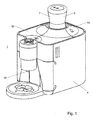
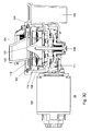
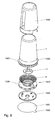
- the system 1 includes a coffee bean cartridge 3 and a coffee brewing apparatus 4.
- the coffee bean cartridge may be of a first type, i.e. a coffee bean packaging cartridge that is not refillable or may only be refillable a very limited number of times or of a second type, i.e. a coffee bean cartridge that is either refillable a number of times higher than the number of times that the coffee bean cartridge of the first type may be refilled or it is refillable an unlimited number of times.
- the coffee bean cartridge 3 is removably connected to the coffee brewing apparatus 4.
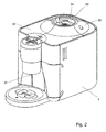
- Figure 2 shows the coffee brewing apparatus without the coffee bean cartridge 3 mounted thereon.
- the coffee bean packaging cartridge 3 of the first and second type comprise a container 7 having an interior volume for containing coffee beans and an exit opening. These coffee beans are roasted and include generally roasted half beans.
- the coffee beans cartridge 3 is closed airtight and/or under vacuum before it is placed on the coffee brewing apparatus 4.
- the coffee bean cartridge 3 can be in the form of a disposable packaging, so that it can be thrown away after it has been emptied.
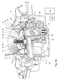
- Figure 3A shows a cartridge of a first type with an anti-refill mechanism, to be described in more detail herein after, also referred to in this description as the first cartridge or the first coffee bean packaging cartridge.
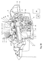
- Figure 3B shows a cartridge of a second type without anti-refill mechanism. also referred to in this description as the second cartridge or the second coffee bean cartridge.
- the cartridge comprises transportation means 6 for enabling transportation of the coffee beans from the interior volume of the container 7 (only partially visible in figures 3 and 3B ) towards the exit opening 29 of the cartridge 3.
- the coffee apparatus is provided with an entrance opening 9 for receiving coffee beans which are transported by means of the transportation means towards the exit opening 29.
- the exit opening 29 extends above the coffee bean entrance opening 9 of the coffee brewing apparatus 4.
- a lower part of the container 7 comprises a funnel 8 which forms part of the transportation means 6.
- the beans of the coffee bean packaging cartridge 3 are guided by means of the funnel 8 towards the exit opening 29 of the cartridge.
- the transportation means comprise a disk element (impellor) of a first type 10, also referred to in this description as first impellor, having several flexible vanes 13.
- the transportation means comprise a disk element (impellor) of a second type 11, also referred to in this description as second impellor, which again comprises several flexible vanes 13.
- the reason for using different impellors lies in the need to use different drive means for driving the impellor in case of anti-refill and without anti-refill mechanism, as will be discussed herein after.
- the movable part (impellor) of the transportation means in this example by rotating the impellor around a second axes 19 extending in a vertical direction, the coffee beans are transported towards the exit opening 29.
- the system further comprises a metering chamber 15.
- the metering chamber is divided in a first chamber portion 23 which is part of the cartridge and a second chamber portion 25 which is part of the coffee brewing apparatus.
- the first chamber portion is located above the second chamber portion.
- the first chamber portion comprises the exit opening 29 of the cartridge and the second chamber portion comprises the entrance opening of the coffee apparatus.
- the first chamber portion is provided with an upstanding side wall 32 comprising an inlet opening 21 for letting pass coffee beans into the metering chamber which coffee beans are transported by means of the transportations means towards the exit opening of the cartridge.
- the transportation means are thus configured for transporting the coffee beans towards and into the metering chamber 15 of the coffee beverage system 1 upon driving of the transportation means.
- This driving is performed by means of a first motor 17 of the coffee apparatus, driving a drive shaft 18 of the coffee apparatus extending along a vertical axis 19. Due to the driving, the impellor 10/11 comprising the vanes 13 rotates around the second vertical axis 19. In this way, the coffee beans are driven in a horizontal direction to the inlet opening 21 of the metering chamber 15.
- the cartridge comprises a small trickle through edge 22 to avoid the uncontrolled entering of coffee beans in the metering chamber 15 when the impellor 10/11 is not rotating.
- the metering chamber 15 comprises the first chamber portion 23 in the cartridge 3 and the second chamber portion 25 in the brewing apparatus 4.
- the bottom 26 of the metering chamber at least comprises a bottom portion 27 which is part of a grinder 28 for grinding coffee beans.
- the coffee beans leave the fist chamber portion 23 and thereby the cartridge 3 via the exit opening 29 of the cartridge 3 and enter the second chamber portion 25 and thereby the coffee brewing apparatus via the entrance opening 9.
- the size of the metering chamber is limited by a top wall 31, the bottom 26 and an upstanding side wall 32.
- the upstanding side wall 32 comprises the upstanding side wall 34 of the first chamber portion and an upstanding side wall 33 of the second chamber portion.
- the second chamber portion comprises about 100- X% of the volume of the metering chamber and the first chamber portion comprises about X% of the volume of the metering chamber wherein X is in the range of 2-50, preferably in the range of 4-30, more preferably in the range of 6-15.
- the bottom part 27 of the metering chamber has a conical shape such that the bottom portion extends downwardly in a direction extending perpendicular to and away from a vertical axis 35.
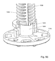
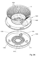
- the grinder 28 in this embodiment is positioned centrically with respect to the second chamber portion 25. Referring now to figures 3C and 3D , the grinder will be described in more detail.
- the grinder comprises a second motor (grinder drive motor) 101 and an upper grinding disk/wheel 102, which may be ceramic or steel.
- the upper grinding disk/wheel is rotationally fixed in its position.
- the second chamber 103 of the metering chamber is shown (referred to by reference 25 in figure 3A and 3B ), which works as dosing funnel.
- the grinder furthermore comprises a manual adjustment lock 104 to adjust the grind fineness setting by the consumer.
- the upper grinding disk 102 is moved up or down in respect to the lower grinding disk/wheel 109 when this key is turned.
- the adjustment lock is operated, the upper grinding disk moves up and down and the lower grinding disk stays in place. In this way the size of the grind at the exit of the grinding disks, i.e. where they almost touch the outside of the grinder, is determined.
- the grinder furthermore comprises an exit location 105 for grinded coffee out of the circular transport channel 110 into the grinded coffee chute 106.
- the grinded coffee chute is a funnel pointing downwards into the brewing device 46 of the coffee brewing apparatus, which is open on the top and placed exactly below this chute when grinding.
- a rotating drive cone 107 (referred to as bottom part with conical shape 27 of the metering chamber in figures 3A and 3B ) is fixed on the main drive shaft 108. This cone ensures the movement and guidance of the beans out of the metering chamber into the grinding section consisting of the upper grinding disk 102 and the lower grinding disk 109, which may be ceramic or steel.
- the upper grinding disk 102 and the lower grinding disk 109 have a suitable milled shape for grinding the coffee beans, as is well known in the art.
- the main drive shaft drives the lower grinding disk 109 and the rotating drive cone 107.
- There is formed a circular transport channel 110 which transports the grinded coffee exiting out of the slit between upper and lower grinding disk to the exit location 105.
- the shape of the channel results in a "no contamination" grinder, wherein virtually no coffee beans/grinded coffee remains after finishing the grinding.
- the grinder comprises a motor transmission/gear 111 and a cone protrusion 112 to force the beans between the grinder disks.
- the lower grinding disk 109 extends around rotating drive cone 107 and the upper grinding disk 102 extends above the lower grinder disk 109.
- the grinder is rotationally driven by motor 101 resulting in the rotation of the drive cone 107 and the lower grinding disk 109. Due to the shape of the cone protrusion 112 upon driving the drive cone 107 and the lower grinding disk coffee beans are moved in an outwardly extending radial direction between the lower grinding disk 109 and the upper grinding disk 102. Because a vertical distance between the lower grinding disk 109 and the upper grinding disk 102 decreases in the outwardly extending radial direction the beans are crunched and cut into grinded coffee.
- grinder 28 supplies grinded coffee to a coffee brewing device 46 (schematically shown in figures 3A and 3B ) of the coffee apparatus.
- the coffee brewing device is arranged to receive a supply of water to extract a coffee beverage from the grinded coffee.
- the coffee beverage is discharged from a coffee beverage exit 37 from the coffee brewing apparatus into a cup or like household receptacle.
- a water supply can be arranged to supply water to the coffee brewing device under pressure for espresso type coffee beverages or may provide a drip feed to the extraction system formed by coffee brewing device.
- the user Before operating the coffee beverage system, the user has to connect the coffee bean cartridge 3 to the coffee brewing apparatus 4.
- connection means for connecting the coffee bean cartridge 3 to the coffee brewing apparatus comprise a recess 50 at an upper side 52 of the coffee brewing apparatus 4.
- the recess 50 is surrounded by a side wall 54 protruding from the upper side of the coffee brewing apparatus 4.
- the user should place the corresponding part of the first/second cartridge, at a lower side of the coffee bean cartridge into the recess.
- the bayonet elements to be described later of the cartridges should be placed in the corresponding openings 58 in the side wall 54 of the recess 50.
- the user should then rotate the cartridge over 50 degrees until reaching the blocking elements 56 for impeding a further rotation of the coffee bean packaging cartridge.
- the exit opening 29 of the first chamber portion 23 is aligned with the coffee inlet 9 of the second chamber portion 25.
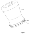
- the second chamber portion 25 in the appliance is closed by means of an appliance closing plate 51( figure 4B )
- the appliance closing plate is being driven by a protrusion 1686 ( figure 6C ) on the neck of the cartridge which slots into a keyhole 53 on the appliance closing plate as the cartridge is being placed into the openings 58 in the side wall 54 of the recess 50.
- a protrusion 1686 figure 6C
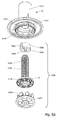
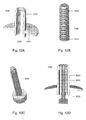
- FIG. 5A-5J An example of a first impellor 10 and its corresponding drive means 1520 is shown in more detail in Figures 5A-5J .
- vanes 13 are preferably made from a resilient material. It is also possible to make the entire impellor 10 from a yieldable resilient material. As illustrated in Figure 5A the vanes 13 do not extend to the perimeter edge of the impellor 10, which may prevent beans from becoming jammed between the vanes 13 and the perimeter aperture.
- the vanes may also be of a flexible material and to provide more flexibility to the vanes the vanes are conveniently also unattached to the impellor base 1577 (bottom), by leaving a gap 1579.
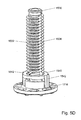
- the first impellor 10 has a hollow hub portion 1511.
- the drive means 1520 are inserted in the recess in the interior of the hollow hub portion 1511.
- the drive means 1520 includes a drive bush 1530 and a nut 1540, which are both part of the first cartridge.
- the drive means 1520 furthermore includes the drive shaft 18 (see figure 3A , 3B ).
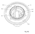
- Nut 1540 is mounted on drive bush 1530. The two pieces are connected by means of the screw thread 1532 covering most of the surface of the drive bush 1530 and the corresponding screw thread 1544 at the interior of nut 1540. Nut 1540, when the system is in operation, climbs down along the screw thread, as will be discussed in detail herein after. Nut 1540 comprises two protrusions 1542, each of the protrusions engaging with one of the four slots 1517 (see figure 5C ), which vertically extend along most of an interior wall 1513 of the hollow hub portion 1511. At the bottom of the impellor base there are edges 1515 being part of a ratchet connection together with scores 1630 (see figure 9A ).
- Drive shaft end 1573 of the coffee preparing appliance has a number of keys 1575 (preferably 4, 6 or 8, referred to with reference number 59 in figure 4 ) for engagement with openings 1716 formed by corresponding protrusions 12 at the bottom side of the drive bush 1530.
- the number of keys may differ between the drive shaft end 1573 and the drive bush 1530.
- a part 1534 at the lower end of the drive bush 1530 is not covered with the screw thread 1532. This part 1534 is opposite to the part of wall 1513 at which the vertically extending slots 1517 are not present.
- interruptions 1536 there are two vertically extending interruptions 1536 (only one of them is visible in figures 5A , 5B ) in the screw thread at opposite sides of the drive bush 1530.
- the interruption in the screw thread at a first side is abrupt and at a second side (the left side in figures 5A , 5B ) is gradual (i.e. a ramp), i.e. the thickness of the screw thread gradually increases from nothing to the normal thickness, as can be appreciated in figures 5D-5G .
- edge 1546 At opposite sides of the interior of nut 1540, there is a corresponding edge 1546 (see figures 5B and 5G ), which is asymmetrically shaped, such that, when the edge 1546 is inserted in one of the slots 1536, the highest thickness of the edge corresponds to the side of the interruptions where the thickness of the screw thread is nil and the lowest thickness correspond to the other side of the corresponding interruption 1536. So, the shape of the edge 1546 and the interruptions 1536 is such that they enable the movement of the nut along the screw thread in downward direction and impede the movement of the nut in the opposite upward direction, as is well known in the art.
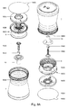
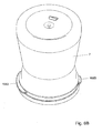
- FIG. 6A , 6B and 6C an embodiment of the coffee bean packaging cartridge 3 of the first type, i.e. with anti-refill impellor 10, is shown in an exploded arrangement, perspective views and cross sectional view.
- This packaging cartridge includes the container 7 defining an interior volume for coffee beans.
- the container 7 is preferably made from a transparent material so that its contents can be seen.
- the container 7 may be partially covered by an outer sleeve (not shown) which may be printed with a description of the kind of coffee beans inside and may also be apertured to reveal a translucent portion of the container 7.
- the container 7 is also provided at a lower end thereof with bayonet formation 1683, 1685 for coupling with the openings 56 in the side wall 54 of the recess 50 of the coffee brewing apparatus 3.
- a closure member 1633 Inserted into an open bottom end of container 7 is a closure member 1633.
- the closure member 1633 has the ribbed funnel 8 for guiding coffee beans towards the impellor 10 and a base flange 1636.
- a rotatable closure disk 1635 is rotatably connectable with respect to the base flange 1636 of the closure member 1633.
- the closure member 1633 and the rotatable closure disk 1635 together form an interface between the cartridge and a coffee brewing apparatus.
- the assemble cartridge can be sealed against deterioration from the ambient air by a sealing membrane 1681 that attaches to the perimeter edge of the container 7.
- the sealing membrane and barrier foil 1681 may again be equipped with a conventional one-way pressure relief valve for venting excess pressure from gases emanated from freshly roasted beans to the exterior of the packaging cartridge.
- a venting valve should open at a pressure of between 0.1 bar and 0.5 bar to prevent deformation of the container by inflation.
- a pulling tab 1682 may be provided.
- Figures 6B and 6C show two different perspective views of the coffee bean packaging cartridge shown in figure 6A .
- the impellor 11 has a hollow hub portion 1571 engageable by the drive shaft end 1573 of the coffee preparing appliance, which for this purpose has a number of keys 1575 (preferably 4, 6 or 8) for engagement with corresponding protrusions, or keys in the interior of hollow hub 1571.
- FIG. 8 an exploded view of the second cartridge is shown. It can be appreciated that, with exception of the used impellors and the drive means thereof, the second cartridge is the same as the first cartridge. Therefore, the perspective view of the second cartridge is the same as the perspective view of the first cartridge, as shown in figures 6B and 6C .
- the outer sleeve 1632 is shown, which may cover the container 7. The outer sleeve may be printed with a description of the kind of coffee beans inside and may also be apertured to reveal a translucent portion of the container 7.
- the interface forming bottom parts of the first/second cartridge are separately shown in more detail in Figures 9A , 9B and 9C .
- the ribbing on funnel 8 as further seen in the exploded view of Figure 9A is useful in preventing sticking of coffee beans to the surface of the funnel 8.
- the rotatable closing disk 1635 has an aperture 1612, which upon appropriate rotation can register with exit opening 29 of the closure member 1633 (see Figure 9B ).
- the closing disk 1635 on its upper surface has protruding there from a first detent 1701 and a second detent 1703 (see Figure 9C ).
- the first abutment is bordered by semi-circular slots 1705 and 1707, respectively.
- protruding from the upper surface of the rotatable closing disk 1635 is a first abutment 1709 and a second abutment 1711 for limiting rotational movement in respect of the exit opening 29.
- first pair of latching arms 1713 is positioned to cooperate with the first detent 1701 in the closed position of the rotatable closure disk 1635.
- the second detent 1703 and the second pair of flexible latching arms also cooperate together in the closed position of the closure disk 1635 and are optional.
- an unlocking element 1721 which is part of a coffee brewing appliance, can engage through the semi-circular slot 1705 in the direction of arrow 1723 when the cartridge is placed on the appliance.
- the unlocking element 1721 has a V-shaped upper contour that forces apart the flexible arms 1713A and 1713B of the first pair of flexible arms 1713. This will then allow rotation of the closure disk 1635 in the direction of arrow 1719 by allowing the first detent 1701 to pass between the spread apart flexible arms 1713A and 1713B.
- This rotating movement is obtained by manually rotating the cartridge with respect to the appliance to engage the bayonet means 1683, 1685 on the container 7 with the counter bayonet formations 56 on the brewing apparatus.
- the operation of the second detent 1703 in respect of the second pair of flexible latching arms is identical and when optionally provided will give additional protection against accidental opening, when not engaged on a coffee brewing apparatus.
- the recess 52 comprises rotatable protruding edges 59 (referred to with reference number 1575 in figures 5A , 5B , 7A and 7B )at its center, which are positioned at the end of the driving shaft 18, which is driven by the first motor 17.
- the corresponding openings 1716 at the bottom side of the drive bush 1530 of the first impellor 10 should be placed, in case of using the cartridge of the first type with anti-refill mechanism.
- the opening 1716 on the bottom side of the second impellor 11 at the bottom side of the second cartridge 3 should be placed on these edges 59.
- the openings 1716 receive the edges 59 when the cartridge is connected with the coffee brewing apparatus.
- the upstanding side wall 54 of the recess 52 may be surrounded by a housing 55, as shown in figures 1-2 .
- the coffee brewing apparatus comprises a control device unit 40 schematically shown in figure 3A and 3B , preferably a microprocessor for controlling the dosing, grinding and brewing process as well as the anti-refill mechanism in case of using a cartridge of the first type.
- the controller may activate these processes after that it has detected that the cartridge 3 has correctly been connected to the coffee brewing apparatus 4.
- the conveying impellor 10/11 For filling of the dosing volume the conveying impellor 10/11 is rotated with a rotational speed in the range of 100 to 500 rpm, and preferably between 250 and 300 rpm. To fill the metering chamber some fifteen revolutions of the impellor 10/11 (i.e. the bottom 1577 and the vanes 13) will normally suffice. However, to ensure filling under even adverse conditions, it may be convenient to allow for some extra revolution such as thirty or twenty-five in total. For filling of the dosing volume the conveying impellor 10/11 is rotated with a rotational speed in the range of 100 to 500 rpm, and preferably between 250 and 300 rpm.
- the appliance will switch from driving the impellor 10/11 to driving its grinder. With the impellor 10/11 immobilised the metering chamber will gradually empty into the grinder. Because the impellor 10/11 is inactive, no beans will escape from container 7, also because of the presence of the trickle through edge 22.
- the controller controls these processes as follows.
- the metering chamber is completely filled with coffee beans.
- the controller controls the first motor 17 to drive the shaft in clockwise direction according to a top view.
- the first/second impellor starts rotating in the clockwise direction.
- the drive shaft 18 rotates the drive bush 1530 and the nut thereon 1540.
- the protrusions 1542 (see figure 5A ) of the nut 1540, which are engaged with the corresponding slots in the wall of the recess of the hollow hub portion 1511 cause the hollow hub portion 1511 and thereby also the bottom 1577 and the vanes 13 connected thereto to rotate.
- the ratchet connection between the bottom 1577 of the impellor 10 and the closure plate 1633 of the first cartridge allows the rotation of the impellor in the clockwise direction.
- the edge 1546 which is positioned in one of the corresponding slots 1536 in the screw thread 1534 of the drive bush 1530, impedes the rotation of the nut 1540 with respect to the drive bush 1530.
- the impellor 10 is driven longer than is required for completely filling or at least substantially completely filling the metering chamber (in this application at least substantially means for example for more than 90%). This is possible, because of the use of the flexible vanes 13.
- the metering chamber is arranged for receiving a portion of coffee beans corresponding to a dosed amount of coffee beans which is preferably necessary for preparing a single serving of coffee beverage, such as a single cup coffee comprising 80-160 ml of coffee.
- a filled metering chamber comprises in this example one dose of coffee beans.
- One dose of coffee beans comprises 5-11, preferably 6-8 grams of coffee beans.
- the control device 40 controls the motor 17 to rotate the drive shaft 18 180° or a little more in the opposite counter clockwise direction.
- the ratchet connection 1515, 1630 (see figures 5B / 9A ) will cause the impellor 10 to stay in its position.
- the rotation force of the drive shaft 18 will cause the drive bush 1530 to rotate, too.
- the nut 1540 is connected by means of a protrusion 1542 and corresponding slot 1517 to the impellor 10, which is stationary, the rotation of the drive bush 1530 will cause the nut 1540 to move down with respect to the drive bush 1530 along the screw thread 1532 until its edge 1546 snaps into one of the corresponding interruptions 1536, again.
- the edge 1546 may be positioned under a little tension some where along the "ramp" of interruption 1536. Wit a small clockwise rotation, the edge 1546 may be brought in a tensionless position in the interruption 1536.
- the controller activates the grinder by activating the second motor 101.
- the grinder is activated longer than is required for emptying the metering chamber and for grinding all the coffee beans which were collected in the metering chamber during the first step.
- the grinder is activated longer than required for completely emptying or at least substantially completely emptying the metering chamber (in this application at least substantially completely emptying means for example for more than 90%).
- the controller controls the brewing device to brew coffee based on the grinded coffee and on heated water.
- the nut 1540 When the cartridge of the first type is used for the first time the nut 1540 is in its initial position shown in figures 5G-5H , at the top end of the drive bush 1530. As the 180° counter clockwise rotation is executed after each complete filling of the metering chamber, as the coffee beans of the first cartridge are used, the nut 1540 climbs down "half a revolution" along the screw thread 1532 of the drive bush 1530. After a first predetermined number of counter clockwise revolutions, the nut leaves the screw thread 1532 and falls to a position next to the part 1534 at the lower end of the drive bush 1530, which is not covered with the screw thread 1532, as shown in 5D-5F.
- the size of the cartridge and the length of the screw thread are chosen such that the first predetermined number of revolutions of the drive shaft resulting in disabling the driving of the impellor is larger than the number of revolutions corresponding to the number of servings of coffee possible with the full cartridge.
- the controller works exactly in the same way, i.e. after filling the metering chamber completely, it controls the motor so that the drive shaft 18 makes a 180° counter clockwise rotation.
- this small counter clockwise rotation does not adversely affect the ability of the second impellor 11 of transporting the coffee beans to the exit opening of the second cartridge.
- the second impellor simply makes a corresponding rotation in the counterclockwise direction but without any coffee beans in the cartridge this rotation has no relevant effect.
- the ratchet connection 1515,1630 (see figures 7B and 9A ) between the second impellor 11 and the closure plate 1633 does not impede this counter clockwise rotation.
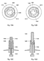
- the impellor and drive means will be described of a cartridge of the first type according to a further embodiment.
- the coffee brewing apparatus should have a longer drive shaft 1220 (see figure 12C ), which is inserted in the hollow interior of a drive bush 1530 (see figure 12B ).
- the drive bush has two snap fingers 1210 near its bottom.
- the drive bush 1530 at its turn is inserted in the interior of a hollow hub portion 1200 of an impellor.
- the interior wall of this hollow hub portion comprises a coil thread 1205 and two edges 1208 (see figure 12A , only one shown).
- the three elements are shown together in their initial position.
- Figure 13A shows a bottom view of the drive shaft, drive bush and impellor for the case that the drive shaft rotates clockwise.
- the snap fingers 1210 of the drive bush lock with the edge 1208 of the interior wall of the hollow hub portion, so that the impellor rotates.
- Figure 13B shows of the drive shaft, drive bush and impellor for the case that the drive shaft rotates counter clockwise for a little over 180°. Due to the ratchet connection between the impellor and the closure member 1633, described herein above, the impellor stays in its position. The snap fingers 1210 bend and lock in their subsequent position. The drive bush 1530 moves up half a revolution or pitch due to its screw thread 1532, which engages with the coil thread 1205 of the hub part of the impellor. By repeating this process after each coffee dosing the drive bush works its way up in the hub part, as shown in figure 13C . After the first predetermined number of revolutions, the drive bush reaches its final position, as shown in figure 13D . In this position, the drive shaft 1220 does not reach the drive bush 1530 and the impellor will not rotate upon rotation of the drive shaft 1220.
- the impellor used in this case is the impellor 10 used for the cartridge with anti-refill described herein above with reference to figures 5A-5J .
- the drive means differ in the following aspects.
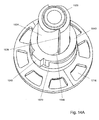
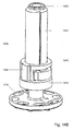
- the drive bush 1530 is not covered with screw thread at all and the nut 1540 does not have screw thread at its interior side. As a result, the nut 1540 may move freely with respect to the drive bush 1530 in a vertical direction but due to the gravity it will be positioned as shown in figures 14A-14B on the top of a flange 1570, which is part of the drive bush 1530.
- the transportation means of the second cartridge for transporting the coffee beans from the container to the metering chamber may be implemented as passive means not driven by a motor, for example by means of a downwardly extending bottom wall for transporting the coffee beans towards the exit opening and into the metering chamber under the influence of gravity only.
- a special means may in that case be required to close the inlet opening of the metering chamber once it is filled with coffee beans.
- the system may be brought into a motor stall condition.
- One option thereto is the engagement of an edge of the rotatable drive means in a corresponding slot of the funnel 8, after the first predetermined revolutions of the drive shaft.
Claims (38)
- Kaffeegetränksystem (1), umfassend eine erste Kaffeebohnenverpackungsvorrichtung (3) und eine Kaffeezubereitungsvorrichtung (4), wobei die erste Kaffeebohnenverpackungsvorrichtung (3) abnehmbar mit der Kaffeezubereitungsvorrichtung (4) verbunden sein kann, wobei die erste Kaffeebohnenverpackungsvorrichtung (3) so angeordnet ist, dass mehrere Portionen Kaffeebohnen aufgenommen und bereitgestellt werden können, wobei die erste Kaffeebohnenverpackungsvorrichtung (3) Folgendes umfasst:einen Behälter (7), umfassend ein Innenvolumen und mindestens eine Ausgangsöffung (29), die einen Kaffeebohnenauslass definiert, wobei das Innenvolumen Kaffeebohnen enthält;ein Transportmittel (6), welches geeignet ist, den Transport der Kaffeebohnen von dem Innenvolumen zu der Ausgangsöffnung (29) der ersten Vorrichtung (3) zu ermöglichen;wobei die Kaffeevorrichtung eine Eingangsöffnung (29) zum Empfangen von Kaffeebohnen, die mithilfe der Transportmittel (6) zu der Ausgangsöffnung (29) der ersten Vorrichtung (3) transportiert werden, ein Mahlwerk (28) zum Mahlen der Kaffeebohnen, die über die Eingangsöffnung in die Kaffeezubereitungsvorrichtung (4) gelangt sind, und eine Brühvorrichtung (46) zum Brühen von Kaffee anhand des mithilfe des Mahlwerks (28) erhaltenen gemahlenen Kaffees umfasst, wobei die Transportmittel (6) der ersten Vorrichtung (3) ein Teil umfassen, das in Bezug auf einen Hauptkörper der ersten Vorrichtung (3) entfernbar ist, um die Kaffeebohnen zu der Ausgangsöffnung (29) der ersten Vorrichtung (3) bei Antreiben der Transportmittel (6) zu transportieren, dadurch gekennzeichnet, dass die Kaffeezubereitungsvorrichtung (4) mit einem Motor (17) und einer vertikal verlaufenden Antriebswelle (18) versehen ist, wobei die Antriebswelle (18) lösbar mit den Transportmitteln (6) der ersten Vorrichtung (3) verbunden ist, um die Transportmittel (6) der ersten Vorrichtung (3) beim Drehen der Antriebswelle (18) durch die Motormittel (17) anzutreiben und dadurch zu bewegen, sodass die Kaffeebohnen zur Ausgangsöffnung (29) der ersten Vorrichtung (3) transportiert werden, wobei die erste Vorrichtung (3) so angeordnet ist, dass, wenn die Antriebswelle (18) mit den Transportmitteln (6) verbunden ist, die Transportmittel (6) der ersten Vorrichtung (3) nach einer ersten vorbestimmten Anzahl an Umdrehungen der Antriebswelle (18) automatisch für den Transport der Kaffeebohnen zur Ausgangsöffnung (29) deaktiviert werden, und wobei das System (1) ferner mit einer zweiten Kaffeebohnenvorrichtung versehen ist, die ebenfalls abnehmbar mit der Kaffeezubereitungsvorrichtung (4) verbunden sein kann, wobei die zweite Kaffeebohnenvorrichtung (3) so angeordnet ist, dass sie mit mehreren Portionen Kaffeebohnen gefüllt werden kann und dass sie diese aufnehmen kann, wobei die zweite Kaffeebohnenvorrichtung (3) Folgendes umfasst:einen Behälter (7), umfassend ein Innenvolumen und mindestens eine Ausgangsöffnung (29), die einen Kaffeebohnenauslass definiert, wobei das Innenvolumen zum Aufnehmen von Kaffeebohnen angeordnet ist;ein Transportmittel (6), das geeignet ist, um das Transportieren der Kaffeebohnen von dem Innenvolumen zu der Ausgangsöffnung der zweiten Vorrichtung zu ermöglichen;wobei die zweite Vorrichtung (3) so an die Kaffeezubereitungsvorrichtung (4) angepasst ist, dass, wenn die zweite Vorrichtung (3) mit der Kaffeezubereitungsvorrichtung (4) verbunden ist, Kaffeebohnen, die mithilfe der Transportmittel (6) der zweiten Vorrichtung (3) zur Ausgangsöffnung (29) der zweiten Vorrichtung (3) transportiert werden, durch die Kaffeezubereitungsvorrichtung (4) über die Eingangsöffung (9) zum Zubereiten von Kaffee empfangen werden können, und wobei die zweite Vorrichtung (3) so angeordnet ist, dass die Transportmittel (6) der zweiten Vorrichtung (3) bei einer vorbestimmten Anzahl an Umdrehungen der Antriebswelle (18) nicht deaktiviert werden oder erst nach einer zweiten vorbestimmten Anzahl an Umdrehungen der Antriebswelle (18) deaktiviert werden, wobei die zweite vorbestimmte Anzahl an Umdrehungen größer als die erste vorbestimmte Anzahl an Umdrehungen ist.
- System (1) nach Anspruch 1, dadurch gekennzeichnet, dass die zweite Vorrichtung (3) nachfüllbar konzipiert ist.
- System (1) nach Anspruch 1 oder 2, dadurch gekennzeichnet, dass die erste Vorrichtung (3) nicht nachfüllbar konzipiert ist.
- System (1) nach einem der vorhergehenden Ansprüche, dadurch gekennzeichnet, dass die erste Vorrichtung (3) so angeordnet ist, dass, wenn die Antriebswelle mit den Transportmitteln (6) verbunden ist, nach einer ersten vorbestimmten Anzahl an Umdrehungen der Antriebswelle (18) in einer anderen oder anderen als für das Antreiben der Transportmittel (6) der ersten Vorrichtung (3) verwendeten Richtung, die Transportmittel (6) der ersten Vorrichtung (3) automatisch für den Transport der Kaffeebohnen zu der Ausgangsöffnung (29) deaktiviert werden.
- System (1) nach einem der vorhergehenden Ansprüche 1-3, dadurch gekennzeichnet, dass die erste Vorrichtung (3) so angeordnet ist, dass, wenn die Antriebswelle (18) mit den Transportmitteln (6) verbunden ist, nach einer ersten vorbestimmten Anzahl an Umdrehungen der Antriebswelle (18) zum Antreiben der Transportmittel (6) der ersten Vorrichtung (3) die Transportmittel (6) der ersten Vorrichtung (3) automatisch für den Transport der Kaffeebohnen zur Ausgangsöffnung (29) deaktiviert werden.
- System (1) nach einem der vorhergehenden Ansprüche, dadurch gekennzeichnet, dass das System (1) geeignet ist, eine automatische Deaktivierung der Transportmittel (6) der ersten Vorrichtung (3) für den Transport der Kaffeebohnen zur Ausgangsöffnung (29) durch Herbeiführen einer Motorabschaltbedingung zu bewirken.
- System (1) nach einem der vorhergehenden Ansprüche 1-5, dadurch gekennzeichnet, dass das System (1) geeignet ist, die automatische Deaktivierung der Transportmittel (6) der ersten Vorrichtung (3) für den Transport der Kaffeebohnen zu der Ausgangsöffnung (29) durch Auskuppeln einer mechanischen Verbindung zu bewirken, sodass die Drehung der Antriebswelle (18) nicht zum Antreiben der Übertragungsmittel oder eines Teils der Übertragungsmittel führt.
- System (1) nach einem der vorhergehenden Ansprüche, dadurch gekennzeichnet, dass der bewegliche Teil der Transportmittel (6) der ersten Vorrichtung (3) ein Scheibenelement (10) umfasst, das sich beim Drehen der Antriebswelle (18) dreht.
- System (1) nach Anspruch 8, dadurch gekennzeichnet, dass das Scheibenelement (10) ein Impeller mit einem Boden und mehreren Schaufeln (13) ist.
- System (1) nach Anspruch 8 oder 9, dadurch gekennzeichnet, dass das Scheibenelement (10) eine Vertiefung aufweist, in der sich das Scheibenelement (10) beim Drehen der Antriebswelle (18) in einer Richtung zum Antreiben der Transportmittel (6) infolge eines Eingreifens von Antriebsmitteln in die Vertiefung dreht.
- System (1) nach Anspruch 4 und 10, dadurch gekennzeichnet, dass die erste Vorrichtung (3) Mittel (1515, 1630) umfasst, um zu bewirken, dass das Scheibenelement (10) beim Drehen der Antriebswelle (18) in einer anderen oder anderen als für das Antreiben der Transportmittel (6) verwendeten Richtung in seiner Position bleibt.
- System (1) nach Anspruch 11, dadurch gekennzeichnet, dass die erste Vorrichtung (3) Mittel (1530) umfasst, um ein Element (1540) der Antriebsmittel in der Vertiefung beim Drehen der Antriebswelle (18) in einer anderen oder anderen als zum Antreiben der Transportmittel (6) verwendeten Richtung zu verschieben.
- System (1) nach Anspruch 12, dadurch gekennzeichnet, dass die Mittel (1530) zum Verschieben so angeordnet sind, dass nach einer ersten vorbestimmten Anzahl an Umdrehungen der Antriebswelle (18) in einer anderen oder anderen als für den Antrieb der Transportmittel (6) verwendeten Richtung das Element (1540) der Antriebsmittel in der Vertiefung eine Position, die einer Motorabschaltbedingung entspricht, oder eine Position, die im Auskuppeln der mechanischen Verbindung (1515, 1630) resultiert, erreicht.
- System (1) nach den Ansprüchen 12 oder 13, dadurch gekennzeichnet, dass die Mittel (1530) zum Verschieben konfiguriert sind, um das Element (1540) durch die Vertiefung in eine Richtung zu verschieben und das Verschieben des Elements in die andere entgegengesetzte Richtung zu verhindern.
- System (1) nach Anspruch 10, dadurch gekennzeichnet, dass die Antriebsmittel die Antriebswelle (18) und eine auf der Antriebswelle (18) montierbare Antriebsbüchse (1530) umfasst.
- System (1) nach Anspruch 11 und einem der vorhergehenden Ansprüche 12-15, dadurch gekennzeichnet, dass die Mittel, um zu bewirken, dass das Scheibenelement (10) beim Drehen der Antriebswelle (18) in einer anderen oder anderen als zum Antreiben der Transportmittel (6) verwendeten Richtung in seiner Position bleibt, eine Rasterverbindung (1515, 1630) zwischen dem Scheibenelement (10) und einer oberen Fläche der Kaffeezubereitungsvorrichtung (4) ist.
- System (1) nach einem der vorhergehenden Ansprüche, dadurch gekennzeichnet, dass die Transportmittel (6) der ersten Vorrichtung (3) eine abwärts verlaufende untere Wand wie beispielsweise einen Trichter (8) des Behälters (7) umfassen, um die Kaffeebohnen unter dem Einfluss von Schwerkraft zu der Ausgangsöffnung (29) der ersten Vorrichtung (3) zu transportieren.
- System (1) nach einem der vorhergehenden Ansprüche, dadurch gekennzeichnet, dass die Transportmittel (6) der zweiten Vorrichtung (3) ein Teil (10) umfassen, das in Bezug auf den Hauptkörper der zweiten Vorrichtung (3) beweglich ist, um beim Antreiben der Transportmittel (6) die Kaffeebohnen zu der Ausgangsöffnung der zweiten Vorrichtung (3) zu transportieren, und dass die Transportmittel (6) lösbar mit der vertikal verlaufenden Antriebswelle (18) der Kaffeezubereitungsvorrichtung (4) verbunden sind, wobei beim Drehen der Antriebswelle (18) mithilfe des Motors (17) die Transportmittel (6) der Vorrichtung (3) angetrieben und dadurch bewegt werden, um die Kaffeebohnen zur Ausgangsöffnung (29) der zweiten Vorrichtung zu transportieren.
- System (1) nach einem der vorhergehenden Ansprüche, dadurch gekennzeichnet, dass das System (1) ferner mit einer Dosierkammer (15) zum Aufnehmen von Kaffeebohnen, die mithilfe der Transportmittel (6) in die Dosierkammer (15) transportiert werden, versehen ist.
- System (1) nach Anspruch 19, dadurch gekennzeichnet, dass die Dosierkammer (15) in einen ersten Kammerabschnitt (23), der Teil der ersten oder zweiten Vorrichtung (3) ist, und einen zweiten Kammerabschnitt (25), der Teil der Kaffeezubereitungsvorrichtung (3) ist, unterteilt ist, wobei der zweite Kammerabschnitt (25) einen unteren Abschnitt (27), der einen Teil des Mahlwerks (28) bildet, umfasst, wobei der untere Abschnitt (27) zum Drehen um eine erste, in vertikaler Richtung verlaufende Achse (35), in der Kaffeezubereitungsvorrichtung (4) angeordnet ist, wobei das System (1) so angeordnet ist, dass sich der untere Abschnitt (27) beim Aktivieren des Mahlwerks (28) um die vertikale Achse (35) dreht, um die Kaffeebohnen aus der Dosierkammer (15) in das Mahlwerk (28) zum Mahlen der Kaffeebohnen zu transportieren.
- System (1) nach Anspruch 20, dadurch gekennzeichnet, dass der untere Abschnitt (27) eine konische Form aufweist, sodass der untere Abschnitt (27) abwärts in einer lotrecht zu und weg von der ersten vertikalen Achse (35) verlaufenden Richtung verläuft und dass der erste Kammerabschnitt (23) die Ausgangsöffnung (29) der ersten oder zweiten Vorrichtung (3) umfasst und der zweite Kammerabschnitt (25) die Eingangsöffnung (9) umfasst.
- System (1) nach Anspruch 21, dadurch gekennzeichnet, dass der erste Kammerabschnitt (23) über dem zweiten Kammerabschnitt (25) angeordnet ist, wobei die Ausgangsöffnung (29) der ersten oder zweiten Vorrichtung (3) über der Eingangsöffnung (9) verläuft.
- System (1) nach einem der vorhergehenden Ansprüche, dadurch gekennzeichnet, dass die erste und/oder die zweite Vorrichtung (3) Schließmittel (1633, 1635) umfasst, um die Ausgangsöffnung (29) zu verschließen, wenn die Vorrichtung (3) nicht mit der Kaffeezubereitungsvorrichtung (4) verbunden ist.
- System (1) nach Anspruch 23, dadurch gekennzeichnet, dass die Schließmittel (1633, 1635) konfiguriert sind, um die Ausgangsöffnung (29) zu öffnen, wenn die Vorrichtung (3) mit der Kaffeezubereitungsvorrichtung (4) verbunden ist.
- System (1) nach einem der vorhergehenden Ansprüche, dadurch gekennzeichnet, dass die Ausgangsöffnung (29) der ersten und/oder zweiten Vorrichtung (3) mit einem entfernbaren Dichtungselement (1681) verbunden ist, welches das Innenvolumen vor der Aktivierung der Vorrichtung (3) abdichtet, wobei bevorzugt das Dichtungselement (1681) das Austreten von Gasen aus der Vorrichtung (3) verhindert.
- System (1) nach einem der vorhergehenden Ansprüche, dadurch gekennzeichnet, dass die Kaffeezubereitungsvorrichtung (4) Verbindungsmittel zum lösbaren Verbinden mit der Kaffeebohnenverpackungsvorrichtung (3) umfasst, wobei die Verbindungsmittel eine Vertiefung (50) an einer oberen Seite der Kaffeezubereitungsvorrichtung (4) umfassen, die Vertiefung (50) von einer Seitenwand (54) umgeben ist und konfiguriert ist, um ein entsprechendes Teil (1683, 1685), das von einer unteren Seite der ersten und/oder zweiten Vorrichtung (3) hervorsteht, aufzunehmen.
- System (1) nach Anspruch 26, dadurch gekennzeichnet, dass die Seitenwand (54) Öffnungen (58) zum Aufnehmen von Bajonettelementen (1683, 1685) der ersten und/oder zweiten Vorrichtung (3) umfasst.
- System (1) nach Anspruch 27, dadurch gekennzeichnet, dass die erste und/oder zweite Vorrichtung (3) die Bajonettelemente (1683, 1685) umfasst.
- System (1) nach einem der vorhergehenden Ansprüche, dadurch gekennzeichnet, dass es Steuermittel (40) umfasst, um die vertikal verlaufende Antriebswelle (18) mit den Motormitteln (17) zu drehen und dadurch die Transportmittel (6) anzutreiben und zu bewegen, um die Kaffeebohnen zu der Ausgangsöffnung (29) der ersten und/oder zweiten Vorrichtung (3) zu transportieren;
die Kaffeebohnen, die über die Eingangsöffnung (9) in die Kaffeezubereitungsvorrichtung gelangt sind, zu mahlen; und
Kaffee aus dem gemahlenen Kaffee und heißem Wasser, erwärmt durch eine Erwärmungsvorrichtung der Kaffeezubereitungsvorrichtung (4), zu brühen. - System (1) nach Anspruch 29 und 19-22, dadurch gekennzeichnet, dass die Steuermittel (40) konfiguriert sind, um die vertikal verlaufende Antriebswelle (18) mit den Motormitteln (17) zu drehen und dadurch die Transportmittel (6) der ersten und/oder zweiten Vorrichtung (3) anzutreiben und zu bewegen, um die Dosierkammer (15) zu füllen, und dass die Steuermittel (40) ferner so konfiguriert sind, um nach dem Füllen der Dosierkammer (15) die Antriebswelle (18) mit den Motormitteln (17) in eine andere oder andere als zum Antreiben der Transportmittel (6) der ersten und/oder zweiten Vorrichtung verwendete Richtung zu drehen.
- System (1) nach einem der vorhergehenden Ansprüche, dadurch gekennzeichnet, dass die erste vorbestimmte Anzahl an Umdrehungen der Antriebswelle (18), die das Deaktivieren der Transportmittel (6) bewirkt, größer ist als die Anzahl an Umdrehungen, die der Anzahl der Portionen Kaffee, die mit der vollen Vorrichtung (3) möglich ist, entspricht.
- Erste Kaffeebohnenverpackungsvorrichtung (3), geeignet zur Verwendung in einem Kaffeegetränksystem (1) nach einem der Ansprüche 1-31, wobei die erste Kaffeebohnenverpackungsvorrichtung (3) angeordnet ist, um entfernbar mit einer Kaffeezubereitungsvorrichtung (4) eines Kaffeegetränksystems (1) verbunden zu werden, wobei die erste Kaffeebohnenverpackungsvorrichtung (3) angeordnet ist, um mehrere Portionen Kaffeebohnen aufzunehmen und zu liefern, und die Folgendes umfasst:einen Behälter (7), umfassend ein Innenvolumen und mindestens eine Ausgangsöffnung (29), die einen Kaffeebohnenauslass definiert, wobei das Innenvolumen Kaffeebohnen aufnimmt;Transportmittel (6), geeignet um den Transport der Kaffeebohnen aus dem Innenvolumen zu der Ausgangsöffnung (29) der ersten Vorrichtung (3) zu ermöglichen;wobei die Transportmittel (6) ein Teil umfassen, das in Bezug auf den Hauptkörper der ersten Vorrichtung (3) beweglich ist, um beim Antreiben der Transportmittel (6) die Kaffeebohnen zu der Ausgangsöffnung (29) der ersten Vorrichtung (3) zu transportieren, dadurch gekennzeichnet, dass die Transportmittel (6) so angeordnet sind, um lösbar mit einer vertikal verlaufenden Antriebswelle (18) einer mit einem Motor (17) versehenen Kaffeezubereitungsvorrichtung (4) verbunden zu werden, wobei die Transportmittel (6) der Vorrichtung angeordnet sind, um beim Drehen der Antriebswelle durch den Motor (17) angetrieben und dadurch bewegt zu werden, um die Kaffeebohnen zu der Ausgangsöffnung (29) der ersten Vorrichtung zu transportieren, wobei die erste Vorrichtung (3) so angeordnet ist, dass, wenn die Antriebswelle (18) mit den Transportmitteln (6) verbunden ist, die Transportmittel (6) der ersten Vorrichtung (3) nach einer ersten vorbestimmten Anzahl an Umdrehungen der Antriebswelle automatisch für den Transport der Kaffeebohnen zu der Ausgangsöffnung (29) deaktiviert werden.
- Erste Vorrichtung (3) nach Anspruch 32, dadurch gekennzeichnet, dass sie nicht nachfüllbar konzipiert ist.
- Erste Vorrichtung (3) nach Anspruch 32 oder 33, dadurch gekennzeichnet, dass sie angeordnet ist, um die automatische Deaktivierung der Transportmittel (6) der ersten Vorrichtung (3) für den Transport der Kaffeebohnen zu der Ausgangsöffnung (29) durch Herbeiführen einer Motorabschaltbedingung zu bewirken.
- Kaffeezubereitungsvorrichtung (4) zur Verwendung in einem System (1) nach Anspruch 4 und den Ansprüchen 19-22, wobei die Kaffeezubereitungsvorrichtung eine Eingangsöffnung (9) zum Aufnehmen von Kaffeebohnen, ein Mahlwerk (28) zum Mahlen von Kaffeebohnen, die über die Eingangsöffnung (9) in die Kaffeevorrichtung gelangt sind, und eine Brühvorrichtung (46) zum Brühen von Kaffee aus dem mithilfe des Mahlwerks (28) erhaltenen gemahlenen Kaffee, und wobei die Kaffeezubereitungsvorrichtung (4) mit einem Motor (17) versehen ist, dadurch gekennzeichnet, dass die Kaffeezubereitungsvorrichtung eine vertikal verlaufende Antriebswelle (18), die lösbar mit den Transportmitteln (6) einer Kaffeebohnenvorrichtung verbunden ist, umfasst, wobei die Kaffeezubereitungsvorrichtung (4) einen Kammerabschnitt (25) zum Aufnehmen von Kaffeebohnen umfasst, der Kammerabschnitt (25) einen unteren Abschnitt (27), der einen Teil des Mahlwerks (28) bildet, umfasst, wobei der untere Teil (27) zum Drehen um eine vertikale Achse (35) angeordnet ist, und Steuermittel umfasst, die zum Drehen der vertikal verlaufenden Antriebswelle (18) mit dem Motor (17) konfiguriert sind, um dadurch die Transportmittel (6) der Kaffeebohnenvorrichtung zum Füllen des Kammerabschnitts anzutreiben und zu bewegen, dass die Steuermittel ferner konfiguriert sind, um nach dem Füllen des Kammerabschnitts die Antriebswelle (18) mit dem Motor (17) in eine andere oder andere als zum Antreiben der Transportmittel (6) einer Kaffeebohnenvorrichtung verwendete Richtung zu drehen, und dass die Vorrichtung (4) so angeordnet ist, dass beim Aktivieren des Mahlwerks (28) der untere Abschnitt (27) um die vertikale Achse (35) gedreht wird, um die Kaffeebohnen aus der Dosierkammer (15) zum Mahlen der Kaffeebohnen in das Mahlwerk (28) zu transportieren.
- Verfahren zur Zubereitung eines Getränks mithilfe eines Kaffeegetränksystems (1) nach einem der Ansprüche 1-31, wenn die erste Kaffeebohnenverpackungsvorrichtung (3) des Kaffeegetränksystems (1) mit dessen Kaffeezubereitungsvorrichtung (4) verbunden ist, wobei das Verfahren folgende Schritte umfasst:Drehen der vertikal verlaufenden Antriebswelle (18) mit den Motormitteln (17), um dadurch die Transportmittel (6) der ersten Vorrichtung (3) anzutreiben und zu bewegen, um die Kaffeebohnen zu der Ausgangsöffnung (29) der ersten Vorrichtung (3) zu transportieren;Mahlen von Kaffeebohnen, die über die Eingangsöffnung (4) in die Kaffeevorrichtung (14) gelangt sind;Brühen von Kaffee aus gemahlenem Kaffee; und,nach einer ersten vorbestimmten Anzahl an Umdrehungen der Antriebswelle (18), automatisches Deaktivieren der Transportmittel (6) der ersten Vorrichtung (3) zum Transportieren der Kaffeebohnen zu der Ausgangsöffnung (29).
- Verfahren zur Zubereitung eines Getränks mithilfe eines Kaffeegetränksystems (1) nach einem der Ansprüche 1-31 wenn die zweite Kaffeebohnenverpackungsvorrichtung (3) des Kaffeegetränksystems (1) mit dessen Kaffeezubereitungsvorrichtung (14) verbunden ist, wobei das Verfahren folgende Schritte umfasst:Drehen der vertikal verlaufenden Antriebswelle (18) mit den Motormitteln (17), um dadurch die Transportmittel (6) der zweiten Vorrichtung (3) anzutreiben und zu bewegen, um die Kaffeebohnen zu der Ausgangsöffnung (29) der zweiten Vorrichtung (3) zu transportieren;Mahlen von Kaffeebohnen, die über die Eingangsöffnung (9) in die Kaffeevorrichtung (4) gelangt sind;Brühen von Kaffee aus gemahlenem Kaffee; und,Drehen der vertikal verlaufenden Antriebswelle (18) mit den Motormitteln (17) in eine Richtung, entgegengesetzt zu der Richtung zum Antreiben der Transportmittel (6) der zweiten Vorrichtung (3), um die Kaffeebohnen zu der Ausgangsöffnung (29) der zweiten Vorrichtung (3) zu transportieren;wobei die Transportmittel (6) der zweiten Vorrichtung (3) nach einer vorbestimmten Anzahl an Umdrehungen der Antriebswelle (13) in eine andere oder eine andere als zum Antreiben der Transportmittel (6) der zweiten Vorrichtung (3) verwendete Richtung nicht deaktiviert werden oder nur nach einer zweiten vorbestimmten Anzahl an Umdrehungen der Antriebswelle (18) deaktiviert werden, wobei die zweite vorbestimmte Anzahl an Umdrehungen größer ist als eine erste vorbestimmte Anzahl an Umdrehungen der Antriebswelle (18), nach der die Transportmittel (6) der ersten Vorrichtung (3) nach Anspruch 33 für das Transportieren der Kaffeebohnen der ersten Vorrichtung (3) zu der Ausgangsöffnung (29) der ersten Vorrichtung (3) automatisch deaktiviert werden.
- Verfahren nach Anspruch 37 zur Verwendung mit einem System (1) nach einem der vorhergehenden Ansprüche 19-22, dadurch gekennzeichnet, dass die Transportmittel (6) angetrieben werden, um die Dosierkammer (15) zu füllen, und dass die Antriebswelle (18) mit den Motormitteln (17) nach dem Füllen der Dosierkammer (15) in eine andere oder eine andere als zum Antreiben der Transportmittel (6) der ersten und/oder zweiten Vorrichtung (3) verwendete Richtung gedreht wird.
Applications Claiming Priority (5)
| Application Number | Priority Date | Filing Date | Title |
|---|---|---|---|
| PCT/NL2010/050077 WO2010095937A1 (en) | 2009-02-17 | 2010-02-17 | Coffee bean packaging cartridge and coffee beverage system including same |
| NL2004274 | 2010-02-22 | ||
| NL2005238 | 2010-08-17 | ||
| NL2005280A NL2005280C2 (en) | 2010-02-17 | 2010-08-26 | Coffee bean packaging catridge and coffee beverage system including the same. |
| NL2005278 | 2010-08-26 |
Publications (2)
| Publication Number | Publication Date |
|---|---|
| EP2409610A1 EP2409610A1 (de) | 2012-01-25 |
| EP2409610B1 true EP2409610B1 (de) | 2014-04-23 |
Family
ID=45370726
Family Applications (5)
| Application Number | Title | Priority Date | Filing Date |
|---|---|---|---|
| EP11154896.2A Not-in-force EP2436288B1 (de) | 2010-02-17 | 2011-02-17 | Kaffeegetränksystem, Kaffeebohnenverpackungskartusche zur Verwendung mit besagtem System, Verfahren zur Zubereitung eines Getränks, Verfahren zum Brühen von Kaffee, Verfahren zur Bereitstellung von Kaffeebohnen, Kartusche für Kaffeebohnenmaterial, Verfahren zur Bereitstellung von Kaffeebohnenmaterial |
| EP14167254.3A Active EP2777452B1 (de) | 2010-02-17 | 2011-02-17 | Kaffeebohnenverpackungskartusche und Verfahren zur Herstellung eines Kaffeegetränks |
| EP11154887.1A Active EP2412281B1 (de) | 2010-02-17 | 2011-02-17 | Kaffeegetränksystem |
| EP11154761.8A Not-in-force EP2436287B1 (de) | 2010-02-17 | 2011-02-17 | System zur Zubereitung eines Kaffeegetränks |
| EP11154834.3A Not-in-force EP2409610B1 (de) | 2010-02-17 | 2011-02-17 | Kaffeebohnenverpackungsvorrichtung und Kaffeegetränksystem damit |
Family Applications Before (4)
| Application Number | Title | Priority Date | Filing Date |
|---|---|---|---|
| EP11154896.2A Not-in-force EP2436288B1 (de) | 2010-02-17 | 2011-02-17 | Kaffeegetränksystem, Kaffeebohnenverpackungskartusche zur Verwendung mit besagtem System, Verfahren zur Zubereitung eines Getränks, Verfahren zum Brühen von Kaffee, Verfahren zur Bereitstellung von Kaffeebohnen, Kartusche für Kaffeebohnenmaterial, Verfahren zur Bereitstellung von Kaffeebohnenmaterial |
| EP14167254.3A Active EP2777452B1 (de) | 2010-02-17 | 2011-02-17 | Kaffeebohnenverpackungskartusche und Verfahren zur Herstellung eines Kaffeegetränks |
| EP11154887.1A Active EP2412281B1 (de) | 2010-02-17 | 2011-02-17 | Kaffeegetränksystem |
| EP11154761.8A Not-in-force EP2436287B1 (de) | 2010-02-17 | 2011-02-17 | System zur Zubereitung eines Kaffeegetränks |
Country Status (15)
| Country | Link |
|---|---|
| EP (5) | EP2436288B1 (de) |
| JP (6) | JP5903052B2 (de) |
| KR (2) | KR101934122B1 (de) |
| CN (6) | CN102970907B (de) |
| AU (6) | AU2011216595B2 (de) |
| BE (5) | BE1019953A5 (de) |
| BR (5) | BR112012020605A2 (de) |
| CA (5) | CA2789858C (de) |
| DE (5) | DE202011109933U1 (de) |
| DK (4) | DK2409610T3 (de) |
| ES (6) | ES2489473T3 (de) |
| MX (2) | MX343947B (de) |
| NL (1) | NL2009293C2 (de) |
| NZ (1) | NZ601807A (de) |
| RU (5) | RU2561027C2 (de) |
Families Citing this family (60)
| Publication number | Priority date | Publication date | Assignee | Title |
|---|---|---|---|---|
| US8043645B2 (en) | 2008-07-09 | 2011-10-25 | Starbucks Corporation | Method of making beverages with enhanced flavors and aromas |
| US8950315B2 (en) * | 2010-11-15 | 2015-02-10 | Conair Corporation | Brewed beverage appliance and method |
| US8646379B2 (en) * | 2010-11-15 | 2014-02-11 | Conair Corporation | Brewed beverage appliance and method |
| BR112015005999A2 (pt) * | 2012-09-21 | 2017-07-04 | Koninklijke Douwe Egberts B V Utrecht | máquina de produção de bebida e sistema |
| EP3785577B1 (de) * | 2013-04-08 | 2022-10-19 | Breville Pty Limited | Verbesserungen an einer kaffeemühle |
| CN105377091A (zh) * | 2013-05-17 | 2016-03-02 | 皇家戴维艾格伯茨有限公司 | 咖啡冲泡设备、咖啡饮料系统以及制备咖啡饮料的方法 |
| EP3054823B1 (de) * | 2013-10-11 | 2021-06-16 | Gehl Foods, LLC | Nahrungsmittelausgabevorrichtung und ventil |
| CN106455848B (zh) * | 2014-05-07 | 2019-06-11 | 特色咖啡股份公司 | 用于制备咖啡的自动化机器 |
| CN107205445B (zh) * | 2014-11-17 | 2021-07-20 | 艾匹克控股有限责任公司 | 用于制备液体产品的系统、可抛弃式盒、以及方法 |
| EP3028609A1 (de) * | 2014-12-04 | 2016-06-08 | Nestec S.A. | Behälter zur Lagerung und Abgabe eines Produkts |
| CN106136912A (zh) * | 2015-04-16 | 2016-11-23 | 新玛德制造厂有限公司 | 一种咖啡机的研磨装置 |
| ITUB20151304A1 (it) * | 2015-05-27 | 2016-11-27 | Fiorenzato M C Srl | Procedimento automatico di taratura per apparecchi macinadosatori di caffe' con dispositivo di pesatura e apparecchio macinadosatore elettronico. |
| IT201600098511A1 (it) * | 2015-10-30 | 2018-03-30 | Simonelli Group Spa | Macchina da caffe' e relativo metodo di estrazione del caffe'. |
| ES2939370T3 (es) * | 2016-01-12 | 2023-04-21 | Freezio Ag | Sistema de dispensador con soporte para cartucho |
| ITUA20161566A1 (it) * | 2016-03-11 | 2017-09-11 | De Longhi Appliances Srl | Macchina da caffè incorporante un macinino |
| DE102016105702A1 (de) * | 2016-03-29 | 2017-10-05 | Melitta Europa Gmbh & Co. Kg | Kaffeemaschine |
| US10405579B2 (en) * | 2016-04-29 | 2019-09-10 | Rai Strategic Holdings, Inc. | Methods for assembling a cartridge for an aerosol delivery device, and associated systems and apparatuses |
| CN109890257A (zh) * | 2016-10-13 | 2019-06-14 | 布瑞威利私人有限公司 | 台式混合器搅动过程监控 |
| AU2017366723B2 (en) | 2016-12-01 | 2021-11-11 | Bedford Systems Llc | Container and opening arrangement for beverage production |
| CN106820990A (zh) * | 2017-02-16 | 2017-06-13 | 周利 | 现磨咖啡机智能控制系统 |
| CN107019429A (zh) * | 2017-03-13 | 2017-08-08 | 苏州咖博士咖啡系统科技有限公司 | 一种咖啡机咖啡豆缺豆检测装置 |
| DE202017001402U1 (de) * | 2017-03-15 | 2018-06-18 | Bean Industries Limited | Kaffeefiltermaschine und System, welches die Kaffeefiltermaschine umfasst |
| EP3597082B1 (de) * | 2017-03-17 | 2021-02-17 | Novadelta-Comércio e Industria de Cafés, Lda. | Kompakter getränkeautomat und methode zur verwendung des getränkeautomaten |
| CN109758000B (zh) * | 2017-03-21 | 2022-08-12 | 威海迅捷智能科技有限公司 | 一种多功能家用豆浆机 |
| CN106859338B (zh) * | 2017-03-21 | 2019-10-18 | 江门市中岸外贸发展有限公司 | 一种家用多功能豆浆机 |
| IT201700038061A1 (it) * | 2017-04-06 | 2018-10-06 | Mazzer Luigi Spa | Macinadosatore per caffe’ con regolazione automatica della granulometria di macinatura e relativo metodo di regolazione |
| DE102017209018A1 (de) * | 2017-05-30 | 2018-12-06 | BSH Hausgeräte GmbH | Getränkeautomat mit optischer Messvorrichtung |
| IT201700059702A1 (it) * | 2017-05-31 | 2018-12-01 | Gruppo Cimbali Spa | Dispositivo dosatore per un portafiltro di una macchina per caffè espresso e metodo di dosatura attuato con tale dispositivo |
| CN110662469B (zh) * | 2017-06-01 | 2023-03-14 | 雀巢产品有限公司 | 具有可存放分配头的饮料机器 |
| EP3629853A1 (de) | 2017-06-01 | 2020-04-08 | Société des Produits Nestlé S.A. | Getränkeautomat mit zusammenklappbarer schnittstelle |
| CN110678107B (zh) * | 2017-06-01 | 2023-03-14 | 雀巢产品有限公司 | 具有稳定支脚的饮料机器 |
| CN108357700B (zh) * | 2017-07-28 | 2019-12-06 | 遨想科创有限公司 | 一种自动磨粉咖啡胶囊制造机 |
| GB201715365D0 (en) * | 2017-09-22 | 2017-11-08 | Cambdev Ltd | Coffee brewing apparatus |
| CN107473411A (zh) * | 2017-09-28 | 2017-12-15 | 福建省谷神农业发展有限公司 | 一种新型曝气头 |
| SG11202005549XA (en) * | 2017-12-22 | 2020-07-29 | Creatrix Ag | Unit of a coffee apparatus having a bean container, a portioning device and a grinder |
| EP3752031A1 (de) * | 2018-02-14 | 2020-12-23 | Société des Produits Nestlé S.A. | Behälter für gebrauchte kapseln für getränkeautomaten |
| US11033152B2 (en) * | 2018-04-26 | 2021-06-15 | Simonelli Group S.P.A. | Set comprising a plurality of mutually connected coffee grinders |
| TW202002866A (zh) * | 2018-05-28 | 2020-01-16 | 義大利商辛巴利集團公司 | 用以依據給定配方將不同咖啡所組成且具有預定重量的劑量的研磨咖啡裝於濃縮咖啡機之過濾把手的設備 |
| IT201800006050A1 (it) * | 2018-06-05 | 2019-12-05 | Dispositivo per la conservazione e l'erogazione di caffe' in grani | |
| CN108433546A (zh) * | 2018-06-07 | 2018-08-24 | 东保集团有限公司 | 一种粉量识别咖啡机 |
| US11812896B2 (en) * | 2018-07-06 | 2023-11-14 | Sunbeam Corporation Pty Ltd | Foodstuff processing system |
| CN108852053B (zh) * | 2018-07-28 | 2021-10-08 | 杨建才 | 豆浆机 |
| CN108814261B (zh) * | 2018-07-28 | 2020-12-29 | 嘉兴琦玥装饰材料有限公司 | 电热炊具 |
| CN108784368B (zh) * | 2018-07-28 | 2020-12-22 | 安徽省华腾农业科技有限公司经开区分公司 | 咖啡机 |
| EP3613319A1 (de) * | 2018-08-21 | 2020-02-26 | Jura Elektroapparate AG | Mahlwerk zum mahlen von mahlgut |
| BR112021010800A2 (pt) * | 2018-12-05 | 2021-10-13 | Smiics Gmbh | Dispositivo para dosagem e/ou para preparar uma mistura a ser preparada, recipiente para receber e dosar um componente, recipiente para receber e dosar o flu-ido e sistema correspondente |
| IT201900001623A1 (it) | 2019-02-05 | 2020-08-05 | La Marzocco Srl | Macchina macina caffè con sistema di dosatura perfezionato e relativo metodo |
| DE102019105427A1 (de) | 2019-03-04 | 2020-09-10 | Wolfgang Mock | Verfahren und Vorrichtung zum Aufbereiten von körnigem Mahlgut oder Mahlgutmischungen |
| WO2020252491A2 (en) * | 2019-06-13 | 2020-12-17 | Ricconics Llc | Coffee system and method |
| US20220272998A1 (en) * | 2019-07-26 | 2022-09-01 | Bcc Product Development, L.L.C. | System and method for filtering a hot beverage |
| IT201900018980A1 (it) * | 2019-10-16 | 2021-04-16 | Roger Tech S R L | Macinacaffè. |
| CN114828660A (zh) * | 2019-12-19 | 2022-07-29 | 雀巢产品有限公司 | 用于烘焙咖啡豆并且用于收集咖啡糠的设备 |
| CN111067359B (zh) * | 2019-12-24 | 2021-07-13 | 皖西学院 | 一种家庭用多功能自动沏茶机 |
| CN113133659B (zh) * | 2020-01-16 | 2022-08-12 | 漳州灿坤实业有限公司 | 咖啡盒 |
| KR20220014008A (ko) * | 2020-07-28 | 2022-02-04 | 엘지전자 주식회사 | 커피추출장치 및 그 제어방법 |
| IT202000018922A1 (it) * | 2020-07-31 | 2022-01-31 | De Longhi Appliances Srl | Dispositivo di macinazione |
| US20240008676A1 (en) * | 2020-11-30 | 2024-01-11 | Manea Vending S.R.L. | Device adapted to deliver constant doses of products, in particular for beverage vending machines |
| DE102021104467A1 (de) | 2021-02-25 | 2022-08-25 | Miele & Cie. Kg | Kaffeeautomat |
| WO2023180410A1 (en) | 2022-03-23 | 2023-09-28 | De' Longhi Appliances S.R.L. Con Unico Socio | Hopper for feeding coffee beans, corresponding grinding apparatus and method, and machine and method for preparing beverages |
| WO2023212911A1 (en) * | 2022-05-06 | 2023-11-09 | Haier Us Appliance Solutions, Inc. | Motorized chute trap for a beverage brewing system |
Family Cites Families (52)
| Publication number | Priority date | Publication date | Assignee | Title |
|---|---|---|---|---|
| JPS5517956Y2 (de) * | 1977-03-02 | 1980-04-25 | ||
| JPS6012227Y2 (ja) * | 1981-05-28 | 1985-04-20 | サンデン株式会社 | コ−ヒ−自動販売機のキャニスタ−の構造 |
| IT1181556B (it) * | 1984-05-30 | 1987-09-30 | Valentino Gasparella | Dosatore volumetrico di caffe' in grani |
| JPH0298825U (de) * | 1989-01-24 | 1990-08-07 | ||
| US4936515A (en) * | 1989-08-17 | 1990-06-26 | Unidynamics Corporation | Coffee bean delivery and grinding system |
| FR2660847B1 (fr) * | 1990-04-12 | 1994-06-03 | Grouard Freres Sa | Moulin a cafe et machine a cafe equipee d'un tel moulin. |
| JPH0646437Y2 (ja) * | 1990-06-22 | 1994-11-30 | 大崎電気工業株式会社 | 飲料抽出用原料供給装置 |
| JPH05161551A (ja) * | 1991-12-11 | 1993-06-29 | Kazuo Enomoto | コーヒーメーカ |
| JPH05317185A (ja) * | 1992-05-19 | 1993-12-03 | Nippon Philips Kk | ミル付きコーヒーメーカー |
| US5241898B1 (en) * | 1992-09-25 | 1999-02-09 | Grindmaster Corp | Coffee dispenser and brewer apparatus |
| DE59306035D1 (de) * | 1993-01-08 | 1997-05-07 | Wmf Wuerttemberg Metallwaren | Kaffeemaschine |
| IT1263828B (it) * | 1993-01-27 | 1996-09-03 | Cimbali Spa | Macchina automatica per caffe' in bevanda,erogabile da solo o, combinato con latte,in forma di cappuccino |
| US5386944A (en) * | 1994-02-17 | 1995-02-07 | Bunn-O-Matic Corporation | Weight controlled grinder and method of grinding coffee beans |
| US5632449A (en) * | 1995-05-08 | 1997-05-27 | Sandolo; Raffael | Customized coffee blending apparatus |
| IT237195Y1 (it) * | 1995-10-05 | 2000-09-05 | Il Caffe Del Professore S R L | Apparecchio elettronico per il controllo della macinazione e deldosaggio di caffe' |
| JPH09173213A (ja) * | 1995-12-26 | 1997-07-08 | Philips Japan Ltd | コーヒー定量自動排出装置 |
| US6339985B1 (en) * | 1998-02-03 | 2002-01-22 | Robert R. Whitney | Coffee maker |
| US6095032A (en) * | 1998-11-06 | 2000-08-01 | La Marzocco International L.L.C. | Coffee grinding, portioning, and pressing device |
| JP2001061664A (ja) * | 1999-08-24 | 2001-03-13 | Toyo Roki Mfg Co Ltd | 飲料作成機 |
| IT1307830B1 (it) * | 1999-12-23 | 2001-11-19 | Vales Maria Pilar Perez | Attrezzatura automatizzata per la vendita di prodotti granulari comeil caffe' od altro. |
| US6589577B2 (en) * | 2000-02-18 | 2003-07-08 | Keurig, Inc. | Disposable single serve beverage filter cartridge |
| IN192798B (de) * | 2000-03-15 | 2004-05-22 | Fianara Int Bv | |
| JP2001314325A (ja) * | 2000-05-09 | 2001-11-13 | Matsushita Electric Ind Co Ltd | コーヒー沸かし器 |
| WO2002074144A2 (en) * | 2001-03-16 | 2002-09-26 | The Procter & Gamble Company | Beverage brewing system |
| US6658989B2 (en) * | 2001-04-11 | 2003-12-09 | Keurig, Incorporated | Re-usable beverage filter cartridge |
| US6572036B2 (en) * | 2001-04-20 | 2003-06-03 | Appliance Development Corporation | Coffee grinder with storage and dispensing means |
| GB2392899A (en) | 2002-09-12 | 2004-03-17 | Beancounter Coffee Company Ltd | Device for containing and grinding coffee beans |
| DE20300928U1 (de) * | 2003-01-22 | 2004-05-27 | Wik Far East Ltd. | Kaffeebohnenbehälter für einen Kaffeeautomaten |
| DE20300933U1 (de) * | 2003-01-22 | 2004-05-27 | Wik Far East Ltd. | Kaffeemühle sowie Kaffeeautomat mit einer Kaffeemühle |
| CN2606563Y (zh) * | 2003-03-10 | 2004-03-17 | 杨家机器厂股份有限公司 | 咖啡研磨机的导流散热装置 |
| KR100552222B1 (ko) * | 2003-04-11 | 2006-02-14 | 주식회사 롯데기공 | 원두커피 분쇄장치 |
| CN2624781Y (zh) * | 2003-06-12 | 2004-07-14 | 王伯风 | 一种家庭用咖啡豆磨碎机 |
| JP2005071254A (ja) * | 2003-08-27 | 2005-03-17 | Fujimori Kogyo Co Ltd | 粉末原料用容器および飲料用ディスペンサ |
| US20050103739A1 (en) * | 2003-11-14 | 2005-05-19 | Brown Kent S. | Beverage container with detachable reusable heat transfer cartridge |
| GB2411105B (en) * | 2004-02-17 | 2006-08-30 | Kraft Foods R & D Inc | An insert and a system for the preparation of beverages |
| TWM257760U (en) * | 2004-03-15 | 2005-03-01 | Yi-Ruei Su | Improved filter drink bag and dedicated flexible filter component for concentrated coffee maker |
| WO2005120313A1 (de) * | 2004-06-14 | 2005-12-22 | Raouf, David | Vorrichtung zur zubereitung von kleinkindnahrung |
| EP1700549B1 (de) * | 2005-03-08 | 2007-08-01 | Saeco IPR Limited | Kaffeemaschine |
| WO2007027206A2 (en) * | 2005-04-11 | 2007-03-08 | Coffee Equipment Company | Machine for brewing a beverage such as coffee and related method |
| JP2006346061A (ja) * | 2005-06-15 | 2006-12-28 | Matsushita Electric Ind Co Ltd | コーヒー沸かし器 |
| ITMI20051224A1 (it) * | 2005-06-29 | 2006-12-30 | De Longhi Spa | Macchina per la produzione di una bevanda a base di caffe' |
| EP1772081A1 (de) * | 2005-10-07 | 2007-04-11 | Cense d'Almez S.A. | Brühvorrichtung für Getränke |
| RU2314738C2 (ru) * | 2006-01-18 | 2008-01-20 | Евгений Анатольевич Логунов | Генератор кофе |
| US20080098901A1 (en) * | 2006-10-25 | 2008-05-01 | Main Power Electrical Factory Ltd. | Coffee mill |
| CN201005518Y (zh) * | 2007-02-13 | 2008-01-16 | 罗世君 | 磨豆泡咖啡机 |
| DE102007008900A1 (de) * | 2007-02-23 | 2008-08-28 | BSH Bosch und Siemens Hausgeräte GmbH | Abnehmbarer Bohnenbehälter mit Drehverschluss |
| GB2447678A (en) * | 2007-03-21 | 2008-09-24 | Dyson Technology Ltd | Dispensing ingredients from hoppers |
| DE202007008814U1 (de) * | 2007-06-21 | 2007-11-29 | Mahlich, Gotthard | Brüheinheit eines Getränkezubereitungsgerätes |
| WO2009047590A1 (en) * | 2007-10-12 | 2009-04-16 | Bich Francois | Grinding system, grinding mill for such grinding system and reload cartridge for such grinding system. |
| DE602008005994D1 (de) * | 2007-12-06 | 2011-05-19 | Seb Sa | Automat für gemahlenen Kaffee |
| US20100080886A1 (en) * | 2008-10-01 | 2010-04-01 | Astra Manufacturing, Inc. | Coffee dispensing machine |
| MX370728B (es) | 2009-02-17 | 2019-12-20 | Douwe Egberts Bv | Cartucho de empacado de grano de cafe y sistema de bebida de cafe que incluye el mismo. |
-
2011
- 2011-02-17 BE BE2011/0096A patent/BE1019953A5/fr not_active IP Right Cessation
- 2011-02-17 EP EP11154896.2A patent/EP2436288B1/de not_active Not-in-force
- 2011-02-17 ES ES11154896.2T patent/ES2489473T3/es active Active
- 2011-02-17 DE DE202011109933U patent/DE202011109933U1/de not_active Expired - Lifetime
- 2011-02-17 CN CN201180019436.XA patent/CN102970907B/zh active Active
- 2011-02-17 ES ES11154887.1T patent/ES2544042T3/es active Active
- 2011-02-17 DE DE202011109919U patent/DE202011109919U1/de not_active Expired - Lifetime
- 2011-02-17 RU RU2012139434/12A patent/RU2561027C2/ru not_active IP Right Cessation
- 2011-02-17 MX MX2012009472A patent/MX343947B/es active IP Right Grant
- 2011-02-17 CA CA2789858A patent/CA2789858C/en active Active
- 2011-02-17 RU RU2012139427/12A patent/RU2576608C2/ru active
- 2011-02-17 BR BR112012020605A patent/BR112012020605A2/pt not_active IP Right Cessation
- 2011-02-17 RU RU2012139435/12A patent/RU2556513C2/ru not_active IP Right Cessation
- 2011-02-17 JP JP2012553835A patent/JP5903052B2/ja active Active
- 2011-02-17 CN CN201180019213.3A patent/CN102970906B/zh not_active Expired - Fee Related
- 2011-02-17 CA CA2789882A patent/CA2789882A1/en not_active Abandoned
- 2011-02-17 BR BR112012020623A patent/BR112012020623B1/pt active IP Right Grant
- 2011-02-17 CN CN201710311880.8A patent/CN107259998B/zh active Active
- 2011-02-17 ES ES11154761.8T patent/ES2493922T3/es active Active
- 2011-02-17 CN CN201180019584.1A patent/CN102946772B/zh not_active Expired - Fee Related
- 2011-02-17 ES ES11154806.1T patent/ES2486302T3/es active Active
- 2011-02-17 BR BR112012020625A patent/BR112012020625A2/pt not_active IP Right Cessation
- 2011-02-17 JP JP2012553833A patent/JP5871398B2/ja not_active Expired - Fee Related
- 2011-02-17 EP EP14167254.3A patent/EP2777452B1/de active Active
- 2011-02-17 DK DK11154834.3T patent/DK2409610T3/da active
- 2011-02-17 AU AU2011216595A patent/AU2011216595B2/en active Active
- 2011-02-17 DK DK11154896.2T patent/DK2436288T3/da active
- 2011-02-17 AU AU2011216589A patent/AU2011216589B9/en not_active Ceased
- 2011-02-17 BR BR112012020602A patent/BR112012020602B8/pt active IP Right Grant
- 2011-02-17 CA CA2789657A patent/CA2789657C/en active Active
- 2011-02-17 DK DK11154761.8T patent/DK2436287T3/da active
- 2011-02-17 CA CA2789450A patent/CA2789450A1/en not_active Abandoned
- 2011-02-17 KR KR1020127023934A patent/KR101934122B1/ko active IP Right Grant
- 2011-02-17 EP EP11154887.1A patent/EP2412281B1/de active Active
- 2011-02-17 DK DK11154806.1T patent/DK2364624T3/da active
- 2011-02-17 JP JP2012553832A patent/JP2013519488A/ja active Pending
- 2011-02-17 EP EP11154761.8A patent/EP2436287B1/de not_active Not-in-force
- 2011-02-17 BE BE2011/0107A patent/BE1019875A5/fr not_active IP Right Cessation
- 2011-02-17 KR KR1020127023935A patent/KR20130018689A/ko active IP Right Grant
- 2011-02-17 DE DE202011109913U patent/DE202011109913U1/de not_active Expired - Lifetime
- 2011-02-17 MX MX2012009476A patent/MX2012009476A/es active IP Right Grant
- 2011-02-17 RU RU2012139428/12A patent/RU2557749C2/ru not_active IP Right Cessation
- 2011-02-17 JP JP2012553831A patent/JP5877165B2/ja not_active Expired - Fee Related
- 2011-02-17 CN CN201180019429.XA patent/CN102946771B/zh active Active
- 2011-02-17 CN CN201180019442.5A patent/CN102984976B/zh not_active Expired - Fee Related
- 2011-02-17 ES ES14167254.3T patent/ES2675643T3/es active Active
- 2011-02-17 AU AU2011216596A patent/AU2011216596B2/en not_active Ceased
- 2011-02-17 DE DE202011109912U patent/DE202011109912U1/de not_active Expired - Lifetime
- 2011-02-17 BR BR112012020626-5A patent/BR112012020626A2/pt not_active IP Right Cessation
- 2011-02-17 NZ NZ601807A patent/NZ601807A/en not_active IP Right Cessation
- 2011-02-17 AU AU2011216590A patent/AU2011216590B2/en active Active
- 2011-02-17 RU RU2012139436/12A patent/RU2544162C2/ru active
- 2011-02-17 AU AU2011216591A patent/AU2011216591B2/en not_active Ceased
- 2011-02-17 ES ES11154834.3T patent/ES2484265T3/es active Active
- 2011-02-17 BE BE2011/0097A patent/BE1019670A3/fr not_active IP Right Cessation
- 2011-02-17 DE DE202011109935U patent/DE202011109935U1/de not_active Expired - Lifetime
- 2011-02-17 CA CA2789851A patent/CA2789851A1/en not_active Abandoned
- 2011-02-17 EP EP11154834.3A patent/EP2409610B1/de not_active Not-in-force
- 2011-02-17 JP JP2012553836A patent/JP5837513B2/ja not_active Expired - Fee Related
- 2011-02-17 BE BE2011/0108A patent/BE1019876A5/fr not_active IP Right Cessation
-
2012
- 2012-08-08 NL NL2009293A patent/NL2009293C2/en active
- 2012-10-10 BE BE2012/0680A patent/BE1021072B1/fr active
-
2016
- 2016-06-30 JP JP2016131081A patent/JP6321727B2/ja active Active
-
2017
- 2017-02-03 AU AU2017200772A patent/AU2017200772B2/en active Active
Also Published As
Similar Documents
| Publication | Publication Date | Title |
|---|---|---|
| EP2409610B1 (de) | Kaffeebohnenverpackungsvorrichtung und Kaffeegetränksystem damit | |
| US8776671B2 (en) | Coffee bean packaging cartridge and coffee beverage system including the same | |
| NL2005280C2 (en) | Coffee bean packaging catridge and coffee beverage system including the same. |
Legal Events
| Date | Code | Title | Description |
|---|---|---|---|
| REG | Reference to a national code |
Ref country code: DE Ref legal event code: R138 Ref document number: 202011109919 Country of ref document: DE Free format text: GERMAN DOCUMENT NUMBER IS 602011006305 Ref country code: DE Ref legal event code: R138 Ref document number: 602011006305 Country of ref document: DE Free format text: GERMAN DOCUMENT NUMBER IS 602011006305 |
|
| AK | Designated contracting states |
Kind code of ref document: A1 Designated state(s): AL AT BE BG CH CY CZ DE DK EE ES FI FR GB GR HR HU IE IS IT LI LT LU LV MC MK MT NL NO PL PT RO RS SE SI SK SM TR |
|
| AX | Request for extension of the european patent |
Extension state: BA ME |
|
| PUAI | Public reference made under article 153(3) epc to a published international application that has entered the european phase |
Free format text: ORIGINAL CODE: 0009012 |
|
| RAP1 | Party data changed (applicant data changed or rights of an application transferred) |
Owner name: KONINKLIJKE DOUWE EGBERTS B.V. Owner name: KONINKLIJKE PHILIPS ELECTRONICS N.V. |
|
| 17P | Request for examination filed |
Effective date: 20120724 |
|
| 17Q | First examination report despatched |
Effective date: 20120928 |
|
| RAP1 | Party data changed (applicant data changed or rights of an application transferred) |
Owner name: KONINKLIJKE DOUWE EGBERTS B.V. Owner name: KONINKLIJKE PHILIPS N.V. |
|
| GRAP | Despatch of communication of intention to grant a patent |
Free format text: ORIGINAL CODE: EPIDOSNIGR1 |
|
| INTG | Intention to grant announced |
Effective date: 20131108 |
|
| RIN1 | Information on inventor provided before grant (corrected) |
Inventor name: MOORMAN, CHRISTIAAN, JOHANNES, MARIA Inventor name: VAN OS, IVO Inventor name: DILLON, CHARLES, KEVIN Inventor name: DE GRAAFF, GERBRAND, KRISTIAAN |
|
| GRAS | Grant fee paid |
Free format text: ORIGINAL CODE: EPIDOSNIGR3 |
|
| GRAA | (expected) grant |
Free format text: ORIGINAL CODE: 0009210 |
|
| AK | Designated contracting states |
Kind code of ref document: B1 Designated state(s): AL AT BE BG CH CY CZ DE DK EE ES FI FR GB GR HR HU IE IS IT LI LT LU LV MC MK MT NL NO PL PT RO RS SE SI SK SM TR |
|
| REG | Reference to a national code |
Ref country code: GB Ref legal event code: FG4D |
|
| REG | Reference to a national code |
Ref country code: CH Ref legal event code: EP |
|
| REG | Reference to a national code |
Ref country code: AT Ref legal event code: REF Ref document number: 663256 Country of ref document: AT Kind code of ref document: T Effective date: 20140515 |
|
| REG | Reference to a national code |
Ref country code: IE Ref legal event code: FG4D |
|
| REG | Reference to a national code |
Ref country code: DE Ref legal event code: R096 Ref document number: 602011006305 Country of ref document: DE Effective date: 20140528 |
|
| REG | Reference to a national code |
Ref country code: DK Ref legal event code: T3 Effective date: 20140724 |
|
| REG | Reference to a national code |
Ref country code: ES Ref legal event code: FG2A Ref document number: 2484265 Country of ref document: ES Kind code of ref document: T3 Effective date: 20140811 |
|
| REG | Reference to a national code |
Ref country code: NL Ref legal event code: T3 |
|
| REG | Reference to a national code |
Ref country code: AT Ref legal event code: MK05 Ref document number: 663256 Country of ref document: AT Kind code of ref document: T Effective date: 20140423 |
|
| REG | Reference to a national code |
Ref country code: LT Ref legal event code: MG4D |
|
| PG25 | Lapsed in a contracting state [announced via postgrant information from national office to epo] |
Ref country code: FI Free format text: LAPSE BECAUSE OF FAILURE TO SUBMIT A TRANSLATION OF THE DESCRIPTION OR TO PAY THE FEE WITHIN THE PRESCRIBED TIME-LIMIT Effective date: 20140423 Ref country code: GR Free format text: LAPSE BECAUSE OF FAILURE TO SUBMIT A TRANSLATION OF THE DESCRIPTION OR TO PAY THE FEE WITHIN THE PRESCRIBED TIME-LIMIT Effective date: 20140724 Ref country code: NO Free format text: LAPSE BECAUSE OF FAILURE TO SUBMIT A TRANSLATION OF THE DESCRIPTION OR TO PAY THE FEE WITHIN THE PRESCRIBED TIME-LIMIT Effective date: 20140723 Ref country code: CY Free format text: LAPSE BECAUSE OF FAILURE TO SUBMIT A TRANSLATION OF THE DESCRIPTION OR TO PAY THE FEE WITHIN THE PRESCRIBED TIME-LIMIT Effective date: 20140423 Ref country code: IS Free format text: LAPSE BECAUSE OF FAILURE TO SUBMIT A TRANSLATION OF THE DESCRIPTION OR TO PAY THE FEE WITHIN THE PRESCRIBED TIME-LIMIT Effective date: 20140823 Ref country code: LT Free format text: LAPSE BECAUSE OF FAILURE TO SUBMIT A TRANSLATION OF THE DESCRIPTION OR TO PAY THE FEE WITHIN THE PRESCRIBED TIME-LIMIT Effective date: 20140423 Ref country code: BG Free format text: LAPSE BECAUSE OF FAILURE TO SUBMIT A TRANSLATION OF THE DESCRIPTION OR TO PAY THE FEE WITHIN THE PRESCRIBED TIME-LIMIT Effective date: 20140723 |
|
| PG25 | Lapsed in a contracting state [announced via postgrant information from national office to epo] |
Ref country code: AT Free format text: LAPSE BECAUSE OF FAILURE TO SUBMIT A TRANSLATION OF THE DESCRIPTION OR TO PAY THE FEE WITHIN THE PRESCRIBED TIME-LIMIT Effective date: 20140423 Ref country code: PL Free format text: LAPSE BECAUSE OF FAILURE TO SUBMIT A TRANSLATION OF THE DESCRIPTION OR TO PAY THE FEE WITHIN THE PRESCRIBED TIME-LIMIT Effective date: 20140423 Ref country code: HR Free format text: LAPSE BECAUSE OF FAILURE TO SUBMIT A TRANSLATION OF THE DESCRIPTION OR TO PAY THE FEE WITHIN THE PRESCRIBED TIME-LIMIT Effective date: 20140423 Ref country code: LV Free format text: LAPSE BECAUSE OF FAILURE TO SUBMIT A TRANSLATION OF THE DESCRIPTION OR TO PAY THE FEE WITHIN THE PRESCRIBED TIME-LIMIT Effective date: 20140423 Ref country code: RS Free format text: LAPSE BECAUSE OF FAILURE TO SUBMIT A TRANSLATION OF THE DESCRIPTION OR TO PAY THE FEE WITHIN THE PRESCRIBED TIME-LIMIT Effective date: 20140423 Ref country code: SE Free format text: LAPSE BECAUSE OF FAILURE TO SUBMIT A TRANSLATION OF THE DESCRIPTION OR TO PAY THE FEE WITHIN THE PRESCRIBED TIME-LIMIT Effective date: 20140423 |
|
| PG25 | Lapsed in a contracting state [announced via postgrant information from national office to epo] |
Ref country code: PT Free format text: LAPSE BECAUSE OF FAILURE TO SUBMIT A TRANSLATION OF THE DESCRIPTION OR TO PAY THE FEE WITHIN THE PRESCRIBED TIME-LIMIT Effective date: 20140825 |
|
| REG | Reference to a national code |
Ref country code: DE Ref legal event code: R097 Ref document number: 602011006305 Country of ref document: DE |
|
| PG25 | Lapsed in a contracting state [announced via postgrant information from national office to epo] |
Ref country code: SK Free format text: LAPSE BECAUSE OF FAILURE TO SUBMIT A TRANSLATION OF THE DESCRIPTION OR TO PAY THE FEE WITHIN THE PRESCRIBED TIME-LIMIT Effective date: 20140423 Ref country code: EE Free format text: LAPSE BECAUSE OF FAILURE TO SUBMIT A TRANSLATION OF THE DESCRIPTION OR TO PAY THE FEE WITHIN THE PRESCRIBED TIME-LIMIT Effective date: 20140423 Ref country code: RO Free format text: LAPSE BECAUSE OF FAILURE TO SUBMIT A TRANSLATION OF THE DESCRIPTION OR TO PAY THE FEE WITHIN THE PRESCRIBED TIME-LIMIT Effective date: 20140423 Ref country code: CZ Free format text: LAPSE BECAUSE OF FAILURE TO SUBMIT A TRANSLATION OF THE DESCRIPTION OR TO PAY THE FEE WITHIN THE PRESCRIBED TIME-LIMIT Effective date: 20140423 |
|
| PLBE | No opposition filed within time limit |
Free format text: ORIGINAL CODE: 0009261 |
|
| STAA | Information on the status of an ep patent application or granted ep patent |
Free format text: STATUS: NO OPPOSITION FILED WITHIN TIME LIMIT |
|
| 26N | No opposition filed |
Effective date: 20150126 |
|
| REG | Reference to a national code |
Ref country code: DE Ref legal event code: R097 Ref document number: 602011006305 Country of ref document: DE Effective date: 20150126 |
|
| PG25 | Lapsed in a contracting state [announced via postgrant information from national office to epo] |
Ref country code: SI Free format text: LAPSE BECAUSE OF FAILURE TO SUBMIT A TRANSLATION OF THE DESCRIPTION OR TO PAY THE FEE WITHIN THE PRESCRIBED TIME-LIMIT Effective date: 20140423 |
|
| PG25 | Lapsed in a contracting state [announced via postgrant information from national office to epo] |
Ref country code: LU Free format text: LAPSE BECAUSE OF FAILURE TO SUBMIT A TRANSLATION OF THE DESCRIPTION OR TO PAY THE FEE WITHIN THE PRESCRIBED TIME-LIMIT Effective date: 20150217 |
|
| REG | Reference to a national code |
Ref country code: CH Ref legal event code: PL |
|
| PG25 | Lapsed in a contracting state [announced via postgrant information from national office to epo] |
Ref country code: LI Free format text: LAPSE BECAUSE OF NON-PAYMENT OF DUE FEES Effective date: 20150228 Ref country code: MC Free format text: LAPSE BECAUSE OF FAILURE TO SUBMIT A TRANSLATION OF THE DESCRIPTION OR TO PAY THE FEE WITHIN THE PRESCRIBED TIME-LIMIT Effective date: 20140423 Ref country code: CH Free format text: LAPSE BECAUSE OF NON-PAYMENT OF DUE FEES Effective date: 20150228 |
|
| REG | Reference to a national code |
Ref country code: IE Ref legal event code: MM4A |
|
| PG25 | Lapsed in a contracting state [announced via postgrant information from national office to epo] |
Ref country code: IE Free format text: LAPSE BECAUSE OF NON-PAYMENT OF DUE FEES Effective date: 20150217 |
|
| REG | Reference to a national code |
Ref country code: FR Ref legal event code: PLFP Year of fee payment: 6 |
|
| PG25 | Lapsed in a contracting state [announced via postgrant information from national office to epo] |
Ref country code: MT Free format text: LAPSE BECAUSE OF FAILURE TO SUBMIT A TRANSLATION OF THE DESCRIPTION OR TO PAY THE FEE WITHIN THE PRESCRIBED TIME-LIMIT Effective date: 20140423 |
|
| REG | Reference to a national code |
Ref country code: FR Ref legal event code: PLFP Year of fee payment: 7 |
|
| PGFP | Annual fee paid to national office [announced via postgrant information from national office to epo] |
Ref country code: DE Payment date: 20170217 Year of fee payment: 7 Ref country code: FR Payment date: 20170217 Year of fee payment: 7 |
|
| PG25 | Lapsed in a contracting state [announced via postgrant information from national office to epo] |
Ref country code: SM Free format text: LAPSE BECAUSE OF FAILURE TO SUBMIT A TRANSLATION OF THE DESCRIPTION OR TO PAY THE FEE WITHIN THE PRESCRIBED TIME-LIMIT Effective date: 20140423 Ref country code: HU Free format text: LAPSE BECAUSE OF FAILURE TO SUBMIT A TRANSLATION OF THE DESCRIPTION OR TO PAY THE FEE WITHIN THE PRESCRIBED TIME-LIMIT; INVALID AB INITIO Effective date: 20110217 |
|
| PGFP | Annual fee paid to national office [announced via postgrant information from national office to epo] |
Ref country code: GB Payment date: 20170216 Year of fee payment: 7 Ref country code: NL Payment date: 20170131 Year of fee payment: 7 Ref country code: BE Payment date: 20170216 Year of fee payment: 7 Ref country code: DK Payment date: 20170216 Year of fee payment: 7 |
|
| PGFP | Annual fee paid to national office [announced via postgrant information from national office to epo] |
Ref country code: TR Payment date: 20170213 Year of fee payment: 7 Ref country code: IT Payment date: 20170221 Year of fee payment: 7 Ref country code: ES Payment date: 20170213 Year of fee payment: 7 |
|
| PG25 | Lapsed in a contracting state [announced via postgrant information from national office to epo] |
Ref country code: MK Free format text: LAPSE BECAUSE OF FAILURE TO SUBMIT A TRANSLATION OF THE DESCRIPTION OR TO PAY THE FEE WITHIN THE PRESCRIBED TIME-LIMIT Effective date: 20140423 |
|
| REG | Reference to a national code |
Ref country code: DE Ref legal event code: R119 Ref document number: 602011006305 Country of ref document: DE |
|
| REG | Reference to a national code |
Ref country code: DK Ref legal event code: EBP Effective date: 20180228 |
|
| REG | Reference to a national code |
Ref country code: NL Ref legal event code: MM Effective date: 20180301 |
|
| GBPC | Gb: european patent ceased through non-payment of renewal fee |
Effective date: 20180217 |
|
| PG25 | Lapsed in a contracting state [announced via postgrant information from national office to epo] |
Ref country code: AL Free format text: LAPSE BECAUSE OF FAILURE TO SUBMIT A TRANSLATION OF THE DESCRIPTION OR TO PAY THE FEE WITHIN THE PRESCRIBED TIME-LIMIT Effective date: 20140423 |
|
| REG | Reference to a national code |
Ref country code: BE Ref legal event code: MM Effective date: 20180228 |
|
| REG | Reference to a national code |
Ref country code: FR Ref legal event code: ST Effective date: 20181031 |
|
| PG25 | Lapsed in a contracting state [announced via postgrant information from national office to epo] |
Ref country code: NL Free format text: LAPSE BECAUSE OF NON-PAYMENT OF DUE FEES Effective date: 20180301 |
|
| PG25 | Lapsed in a contracting state [announced via postgrant information from national office to epo] |
Ref country code: DE Free format text: LAPSE BECAUSE OF NON-PAYMENT OF DUE FEES Effective date: 20180901 Ref country code: DK Free format text: LAPSE BECAUSE OF NON-PAYMENT OF DUE FEES Effective date: 20180228 |
|
| PG25 | Lapsed in a contracting state [announced via postgrant information from national office to epo] |
Ref country code: FR Free format text: LAPSE BECAUSE OF NON-PAYMENT OF DUE FEES Effective date: 20180228 Ref country code: BE Free format text: LAPSE BECAUSE OF NON-PAYMENT OF DUE FEES Effective date: 20180228 Ref country code: GB Free format text: LAPSE BECAUSE OF NON-PAYMENT OF DUE FEES Effective date: 20180217 Ref country code: IT Free format text: LAPSE BECAUSE OF NON-PAYMENT OF DUE FEES Effective date: 20180217 |
|
| REG | Reference to a national code |
Ref country code: ES Ref legal event code: FD2A Effective date: 20190801 |
|
| PG25 | Lapsed in a contracting state [announced via postgrant information from national office to epo] |
Ref country code: ES Free format text: LAPSE BECAUSE OF NON-PAYMENT OF DUE FEES Effective date: 20180218 |
|
| PG25 | Lapsed in a contracting state [announced via postgrant information from national office to epo] |
Ref country code: TR Free format text: LAPSE BECAUSE OF NON-PAYMENT OF DUE FEES Effective date: 20180217 |