EP2404010B1 - Profilanschlussleiste mit einer dichtvorrichtung zur fugenabdichtung - Google Patents
Profilanschlussleiste mit einer dichtvorrichtung zur fugenabdichtung Download PDFInfo
- Publication number
- EP2404010B1 EP2404010B1 EP10708117.6A EP10708117A EP2404010B1 EP 2404010 B1 EP2404010 B1 EP 2404010B1 EP 10708117 A EP10708117 A EP 10708117A EP 2404010 B1 EP2404010 B1 EP 2404010B1
- Authority
- EP
- European Patent Office
- Prior art keywords
- sealing
- strip
- adhesive
- sealing device
- joint
- Prior art date
- Legal status (The legal status is an assumption and is not a legal conclusion. Google has not performed a legal analysis and makes no representation as to the accuracy of the status listed.)
- Active
Links
Images


Classifications
-
- E—FIXED CONSTRUCTIONS
- E04—BUILDING
- E04F—FINISHING WORK ON BUILDINGS, e.g. STAIRS, FLOORS
- E04F13/00—Coverings or linings, e.g. for walls or ceilings
- E04F13/02—Coverings or linings, e.g. for walls or ceilings of plastic materials hardening after applying, e.g. plaster
- E04F13/04—Bases for plaster
- E04F13/06—Edge-protecting borders
- E04F13/068—Edge-protecting borders combined with mesh material or the like to allow plaster to bond therewith
-
- E—FIXED CONSTRUCTIONS
- E06—DOORS, WINDOWS, SHUTTERS, OR ROLLER BLINDS IN GENERAL; LADDERS
- E06B—FIXED OR MOVABLE CLOSURES FOR OPENINGS IN BUILDINGS, VEHICLES, FENCES OR LIKE ENCLOSURES IN GENERAL, e.g. DOORS, WINDOWS, BLINDS, GATES
- E06B1/00—Border constructions of openings in walls, floors, or ceilings; Frames to be rigidly mounted in such openings
- E06B1/62—Tightening or covering joints between the border of openings and the frame or between contiguous frames
- E06B1/68—Tightening or covering joints between the border of openings and the frame or between contiguous frames by profiled external parts
-
- E—FIXED CONSTRUCTIONS
- E04—BUILDING
- E04F—FINISHING WORK ON BUILDINGS, e.g. STAIRS, FLOORS
- E04F13/00—Coverings or linings, e.g. for walls or ceilings
- E04F13/02—Coverings or linings, e.g. for walls or ceilings of plastic materials hardening after applying, e.g. plaster
- E04F13/04—Bases for plaster
- E04F13/06—Edge-protecting borders
- E04F2013/063—Edge-protecting borders for corners
-
- E—FIXED CONSTRUCTIONS
- E04—BUILDING
- E04F—FINISHING WORK ON BUILDINGS, e.g. STAIRS, FLOORS
- E04F13/00—Coverings or linings, e.g. for walls or ceilings
- E04F13/02—Coverings or linings, e.g. for walls or ceilings of plastic materials hardening after applying, e.g. plaster
- E04F13/04—Bases for plaster
- E04F13/06—Edge-protecting borders
- E04F2013/066—Edge-protecting borders for expansion joints between two plaster layers
-
- E—FIXED CONSTRUCTIONS
- E06—DOORS, WINDOWS, SHUTTERS, OR ROLLER BLINDS IN GENERAL; LADDERS
- E06B—FIXED OR MOVABLE CLOSURES FOR OPENINGS IN BUILDINGS, VEHICLES, FENCES OR LIKE ENCLOSURES IN GENERAL, e.g. DOORS, WINDOWS, BLINDS, GATES
- E06B1/00—Border constructions of openings in walls, floors, or ceilings; Frames to be rigidly mounted in such openings
- E06B1/62—Tightening or covering joints between the border of openings and the frame or between contiguous frames
- E06B2001/624—Tightening or covering joints between the border of openings and the frame or between contiguous frames with parts to be embedded in the stucco layer or otherwise linked to this layer
-
- E—FIXED CONSTRUCTIONS
- E06—DOORS, WINDOWS, SHUTTERS, OR ROLLER BLINDS IN GENERAL; LADDERS
- E06B—FIXED OR MOVABLE CLOSURES FOR OPENINGS IN BUILDINGS, VEHICLES, FENCES OR LIKE ENCLOSURES IN GENERAL, e.g. DOORS, WINDOWS, BLINDS, GATES
- E06B1/00—Border constructions of openings in walls, floors, or ceilings; Frames to be rigidly mounted in such openings
- E06B1/62—Tightening or covering joints between the border of openings and the frame or between contiguous frames
- E06B2001/628—Separate flexible joint covering strips; Flashings
Definitions
- the invention relates to a profile connection strip with a sealing device for sealing a joint between a component attached to a wall and the profile connection strip provided for connecting a cover layer of the wall, with the features of the preamble of claim 1.
- a generic plaster strip, profile strip or profile connection strip for frames of windows or doors has become known, which has a base section with web sections for connection to a plaster layer, a frame fastening leg for connection to the frame and a sealing lip for covering and sealing the joint formed between the frame and the base section .
- These named components of the profile strip are formed as a structural unit.
- the frame attachment leg is connected to the base section, in particular movably, via a convexly curved connection section.
- a support body is formed as part of the frame mounting leg or it is z.
- B. a flexible foam strip which is connected via adhesive layers with the frame attachment leg and the base portion.
- the supporting body holds the frame attachment leg in a defined position and thus facilitates the assembly of the profile strip.
- the support body In the event of relative movements between the profile strip and the frame when installed can the support body z.
- B. detach from the frame mounting leg and allow this an adjustment movement.
- the sealing lip can adapt to the relative movement through elastic deformation and can continue to seal the joint while continuing to cover the connection section.
- this plastering strip is that the frame attachment leg, the sealing lip and the support body together with the base section form a solid structural unit and the sealing device formed by the sealing lip is therefore specially designed for this plastering strip and is therefore not a universally applicable sealing device that can also be used for other plastering strips would be usable. It is also disadvantageous that this solid structural unit is formed by a relatively rigid extruded profile strip. This profile strip cannot therefore be rolled up or wound up. Another disadvantage is that a separate, cost-intensive extrusion tool has to be made for each profile variant.
- a sealing device which has a foam strip as a supporting body, which on its two opposite outer surfaces each have an adhesive layer both on a profile bar as well as on a component such.
- B. a window or door frame in a building wall can be fixed.
- the foam strip which is formed with improved properties compared to the prior art to compensate for such an increased relative movement between the profile strip and the component, can no longer adapt due to a lack of sufficient elasticity and will tear. so that the joint between the profile strip and the component is no longer sealed. Furthermore, the appearance of this sealing device is in need of improvement.
- a sealing device of a sealing arrangement for a joint which is formed by an assembly device and a sealing device, which are arranged one behind the other in the joint and have different properties with regard to their adaptation to relative movements between a profile strip and a component, which between them the joint form.
- the assembly device is used for initial positioning the profile strip during assembly and the sealing device serves to permanently seal the joint.
- This sealing arrangement thus requires two independent assembly or sealing devices, which are arranged one behind the other in the joint, and is correspondingly expensive and requires greater installation space in the joint.
- the appearance could be improved.
- the DE 10 2004 015 556 B4 discloses a plaster connection strip having a base part, a plaster part and a flexible connecting wall in an integral construction.
- the base part is attached to a component using foam adhesive tape.
- the flexible connecting wall deforms in accordance with the relative movement and continues to provide a joint seal.
- Such a plaster connecting strip has a comparatively complex design and is visually unattractive, particularly in the case of relative movements, due to the multi-layered design with staggered depths. The appearance is therefore in urgent need of improvement.
- a material bridge that can be separated is also required for this technique. This can only be produced at increased cost and restricts the further technical design options for this plaster connection strip.
- the object of the invention is to create a profile connection strip of the type mentioned at the outset, which ensures reliable and permanent sealing of a joint even with larger relative movements between the component and the profile connection strip in the installed position, and to provide a sealing arrangement with such a profile connection strip with improved properties.
- the object is achieved according to the invention with the profile connection strip mentioned at the outset in that the sealing device or the sealing strip and the supporting body are formed free of portions of the profile connection strip and the component.
- a component for connection to a sealing device which can also be referred to as a sealing strip unit, is, for example, a profile strip or a part of a building or another structure.
- a component can be, for example, a door frame, window frame, built-in furniture, roller shutter box, staircase, washbasin, shower cubicle, tile, sheet metal strip, board, beam, masonry, concrete wall, plaster, drywall or a window sill.
- a component can also be a profile connection strip, such as the known reveal connection profiles or roof ventilation profiles or plaster finishing profiles.
- two profile strips can form the components and come to rest on the building parts on both sides of the expansion joint.
- Profile strips can, for example, be embedded in a building surface, as is usual with layers of plaster and layers of spatula. But profile strips can also be arranged on a building surface, as is usual in renovation.
- a common joint extends along z.
- B. a surface of a wall and has a certain depth perpendicular to the surface and a certain width between two components, the width is constant with parallel arranged components and can have different widths over their depth with non-parallel surfaces of the two components.
- joints on vertical parts of buildings can be arranged both vertically and horizontally, with horizontal joints generally being more difficult to wick away than vertical joints. All of these joints must be designed to be permanently tight in accordance with the known regulations and requirements.
- the sealing device or the sealing tape preferably seals with regard to one or more requirements specified in the known standards and regulations, for example with regard to the ift guideline MO-01/1 (issued by the testing institute ift in Rosenheim, Germany). These include, for example, weather influences from wind, rain, light or temperature (cold and heat).
- a joint on the inside of the room is to be designed to be more vapor diffusion-tight than a joint on the outside of the room.
- a joint on the inside of the room is preferably airtight and a joint on the outside of the room is preferably impervious to driving rain.
- Interior joints are often sealed against the usual influences during use, such as moisture in damp rooms. Sealing is preferably permanent and not just short-term.
- the seal is preferably designed to be sufficiently resilient with regard to the mechanical loads to be expected, for example cleaning work.
- a design-related and/or weather-related relative movement can occur between the components. Depending on various factors, these relative movements can take place in the three spatial directions and have different values.
- the relative movement can generate longitudinal movements and/or transverse movements and/or changes in the distance between the two components.
- the sealing device solves the actual technical challenge, namely permanent sealing of a joint with simultaneous dynamic relative movement.
- the supporting body of the sealing device according to the invention has an elongated shape, e.g. B. in the form of a band or a strip or even a thin layer and is expediently made of materials that allow it to ensure the mutual positioning of the two components in the assembled position.
- the support body does not necessarily have to be tight in every design in the sense of a seal, since the sealing strip according to the invention is responsible for the essential sealing and preferably for this only.
- the supporting body Between its two outer surfaces provided for attachment, the supporting body has at least one end face and usually two opposite end faces corresponding to its shape.
- the sealing tape can tightly cover each of the two end faces, which can be flat or curved.
- the front side is z. B. a flat or curved surface or even just a narrow strip or is formed in the form of a line depending on the design of the supporting body.
- a relative movement of the two outer surfaces of the support body of a sealing device according to the invention takes place due to a corresponding relative movement of at least one of the two components, each by means of an external connection device such.
- an adhesive layer or bonding or an integral formation are connected to the supporting body.
- the primary task of the support body is to provide assembly-stable positioning or a position-stable connection of the components until assembly is complete. In a preferred embodiment, it supports and improves the sealing properties of the sealing device.
- a sealing device provides both an assembly device and a sealing device in a design that is spatially integrated into one another.
- the assembly device establishes a positionally stable connection of the components and is used for the initial positioning of the sealing device during assembly, while the sealing device is used for the permanent sealing of the joint.
- a load-bearing stability or position-stable connection for mutual positioning of two components until assembly or processing is complete can be immobile or mobile.
- a supporting body of a sealing device according to the invention can allow a certain relative movement of the components to one another when force is applied during assembly. After the end of this force, the support body will preferably return to the starting position.
- a positionally stable connection does not mean any connection between any two components.
- one component can be stable, massive and heavy and the other component can be light, e.g. B. a molding.
- a positionally stable connection holds a relatively light component, such as a profile strip, to another relatively light component or to a relatively heavy component.
- a mutual positionally stable connection of two relatively heavy components is not provided by the sealing device.
- the assembly forces are smaller than the internal holding force, adhesive force or adhesive force on the supporting body. These internal forces are in turn smaller than the external holding force, adhesive force or adhesive force between the supporting body and the respective component. These external forces are preferably in turn smaller than the expansion or tensile forces that can be absorbed by the sealing strip during relative movements.
- Fastenings or connections or external connections are made, for example, by adhesive devices. In principle, however, other types of tight attachments or connections such as vulcanization or welding or clamping are also possible.
- the essential advantage of the sealing device according to the invention is therefore the flexible adaptation of the sealing strip to the respective, even large, relative movements or joint movements with a simple, cost-effective and space-saving design and the reliable tightness due to the firm connection of the edges of the sealing tape with the components.
- the sealing tape or the sealing device is designed and designed according to its application and the size of the relative movements to be expected. A separate, cost-intensive extrusion tool does not have to be made for each profile variant.
- the various embodiments of the sealing device can, for example, be assembled in a simple manner from suitable components by means of a device. At the same time, the part of the sealing device that is visible in the installed state can advantageously be made narrow.
- the sealing device establishes the positionally stable positioning of the two components relative to one another due to the dimensionally and positionally stable design.
- the sealing device or sealing arrangement according to the invention consists of only one unit and can therefore be produced easily and inexpensively. It also requires little space in the joint. It is essential that the sealing device or the sealing strip and the supporting body are formed independently of the component. This means that no parts of one of the components or a profile strip are integrated. The sealing device can therefore also be used universally.
- the appearance or the optical presentation of the sealing device is improved and perfect compared to the prior art due to the technical solution of the movement absorption. It is particularly preferred that the sealing device or the sealing tape forms a joint cover in the installed position. Thus, no other element is required for a cover.
- a joint cover is that part of a joint seal that is visible on the visible side when installed or during relative movements in the joint.
- a joint cover provides a flawless optical presentation in the stationary installation state or in the various movement positions with relative movements. At the same time, the joint is and remains sealed by the sealing device in accordance with the relevant standards.
- the sealing strip and/or the support body is/are connected to the profile connection strip or can be connected to the component by means of a respective external connection device and the external connection device is essentially planar.
- the portion of a component intended for connection to the sealing device is also planar. This simplifies the production of the connection, since flat surfaces can be connected simply, universally, defined and inexpensively, for example by means of an adhesive device.
- the sealing strip is preferably fastened or connected to the supporting body with its two edges in such a way that it always covers the associated end face of the supporting body in a sealing manner.
- the support body in cross section z. B. is shaped substantially rectangular with two parallel outer surfaces, the two edges of the sealing tape are expediently attached or integrated to the corner areas of the support body or to edge portions of the outer surfaces.
- Each outer surface of the supporting body can have a recess or indentation adjacent to the end face, so that when the sealing tape is applied thereto, there is a planar or planar surface or outer surface to which a component is to be fastened.
- the sealing strip can also be formed integrally with the supporting body, for example by coextrusion.
- a strip-shaped material can, for example, essentially form the sealing strip and the supporting body in one piece. For this purpose, it can be manufactured or formed or processed accordingly.
- the sealing tape is integrally formed at one of its edges with the supporting body and at the other edge on the supporting body z. B. is fixed by gluing or welding.
- the transition from the sealing tape to the supporting body can be stepless.
- the location of the transition can also change locally in the case of relative movements when the sealing device reacts according to the invention, in particular in the case of large relative movements change or move.
- the support body is primarily defined by the provision of the positionally stable connection until assembly is complete. If this connection is then lost, for example due to relative movements, the former support body can also function as part of the sealing strip, depending on the technical design of the sealing device.
- the sealing tape or a middle section of the sealing tape is expediently connected to the outer surface of the supporting body or applied to it at least via a sealing tape strip on the edge.
- the sealing tape strip can cover a section or strip of the outer surface adjacent to the end face or the entire outer surface.
- the sealing tape strip can thus merge into the supporting body.
- this strip of sealing tape can also form a base for fastening a component or remain without a fixed connection to the component.
- the sealing tape strip is preferably indirectly connected to the components in a sealing manner via the supporting body.
- the sealing strip preferably has such a width between its two edges on the supporting body that it can adapt to relative movements of the components. If the sealing tape is flexible but not stretchable, its two edges can move away from each other when the supporting body expands until it is stretched. When delivered or in the assembled position, the sealing strip can be curved in a bulbous or U-shaped manner over the end face of the support body, so that it can compensate for the displacement corresponding to the size of the curvature. In particular, it therefore has a movement reserve due to the possibility of flexible deformation.
- the sealing tape is flexible and in particular extensible, if its two edges are excessively spaced apart, it can accommodate this displacement.
- the sealing strip can be arranged both curved and flat in front of the end face of the support body, both in the delivered condition and in the installed position. In particular, it therefore has a movement reserve by means of deformation through stretching. When stretched, tensile forces occur in the sealing tape.
- Adaptation to a relative movement thus takes place, for example, by bending and/or stretching the sealing strip.
- an adjustment can take place, for example, in the event of expansion or compression or longitudinal shearing or transverse shearing or a mixed form of these relative movements.
- a section of the sealing device adjacent to the sealing strip can also be included in an adjustment.
- the sealing tape can detach from the respective component continuously or in stages in sections, with a certain section of the sealing tape or the sealing device obviously having to remain tightly connected to the component. This must be taken into account when designing a sealing device.
- the sealing device must be tight at least in that area or section that extends between these components in the installed position or in the operating state after a relative movement of the components. This is at least the middle section of the sealing strip and, if necessary, sections of the sealing device that become detached from the components. Those areas or sections of the sealing device that always remain attached to the components do not necessarily require such tightness.
- the sealing strip is formed from at least two sealing strips or sealing strip sections which are connected to one another in front of the end face of the supporting body and on the other hand are each attached to the supporting body or formed integrally with the supporting body.
- the two sealing strip sections are tightly connected to one another in an overlapping connection area.
- the two sealing strip sections are formed from a single sealing strip which is folded in a U-shape and whose two legs form the two sealing strips and whose strip middle section can perform an adjustment movement when the components move relative.
- the sealing device or the supporting body or the sealing strip is formed in layers, in the form of a strip, in the form of strips or in the form of a block and/or has a linear, rectangular, square, triangular, trapezoidal or elliptical cross-section.
- the sealing tape or the two sealing tape strips or the sealing tape sections or the supporting body or the layers of the supporting body or outer surfaces of the supporting body are arranged in the layered arrangement - one above the other or next to one another, depending on the perspective or installation position - preferably parallel or at least essentially parallel to one another. However, they can also be arranged non-parallel, with the central connection means in cross-section e.g. B. is wedge-shaped. In this way, different configurations of the sealing device can be implemented, which are adapted to a respective installation situation of two components.
- the supporting body or the inner supporting layer can be, for example, paper, cardboard, fleece, felt, fabric, fabric, foil or the like. Mixed forms or multi-layer combinations can also provide the desired properties.
- the sealing device or the supporting body or the inner supporting layer or the sealing tape is a foam tape or foam adhesive tape or a sealing or adhesive compound.
- foam tape or foam adhesive tape or a sealing or adhesive compound can be set and adjusted in its thickness for the respective application or the joint to be sealed. Due to its thickness, such material can help to shape the shape and size of the middle section of the belt.
- Such material is preferably compressible and can therefore also be used in the case of compression as well as narrowing joints due to its flexible adaptability. The choice of material also determines the force that can be transmitted in each case and supports the production of the preferred balance of forces, which promotes the function of the sealing device.
- the supporting body is preferably made up of a supporting layer or of at least two supporting layers, which are connected to one another in particular by means of a central connecting device.
- the supporting body In the event of excessive relative movement or relative distance of its outer surfaces, the supporting body will preferably separate between the edges of the sealing tape, between the sealing tape strips or its outer surfaces, or two supporting layers of the supporting body will separate from one another.
- the holding power of the central connection device is determined by its technical design. If the central connecting device is a foam adhesive tape, for example, then the holding force is determined by the adhesive force of the adhesive connections and/or the breaking force of the foam material. The lower force determines the maximum holding force. This design also determines the force that can be transmitted in each case and supports the establishment of the preferred balance of forces, which promotes the function of the sealing device.
- an external connection device for fixing the supporting body and/or the sealing tape or sealing tape strip to a component is provided on the sealing device.
- an external connecting force of the external connecting device is greater than an internal connecting force of a central connecting device or an internal material force counteracting a separation of the supporting body.
- the holding force of the two external connection devices on the associated components is therefore preferably set to be greater than the holding force of the central connection device. This ensures that the sealing device does not become detached from one of the two components after processing when relative movements occur, but that the central connecting device gives up its connecting property without further measures.
- the sealing device always seals the joint even with larger relative movements, even if the weaker central connecting device allows the two sealing strips to move away from one another or detach from the central connecting device in accordance with the relative movements.
- the holding force of the external connection devices can be set in such a way that a certain detachment of at least one of the sealing tapes from the associated component in the area of the middle section of the sealing tape is possible in order to be able to follow large relative movements, but with a sufficient area of the sealing tape remaining firmly and tightly bonded .
- each transmittable force co-determined and supports the production of the preferred balance of power, whereby the function of the sealing device is favored.
- a section of the sealing tape on the visible side forms a joint cover. This changes its shape and dimension depending on the respective relative movement and provides a flawless optical presentation.
- the force that can be absorbed by the sealing tape or the sealing tape strips is preferably set to be greater than the external connecting force or holding force of the two external connecting devices.
- the middle section of the sealing strip is in no way destroyed and the seal remains secured.
- the middle section of the belt can not only be bent, but also pulled and/or stretched.
- a section of a sealing band adjacent to the middle section of the band is included in an adjustment.
- This design also determines the force that can be transmitted in each case and supports the establishment of the preferred balance of forces, which promotes the function of the sealing device.
- a central connecting device preferably connects a plurality of supporting layers of the supporting body to one another and/or connects one or more supporting layers of the supporting body to the sealing tape and/or the sealing tape strips.
- the central connection device can also be an inner support layer, each with an adhesive device for connecting the inner support layer to the sealing tape or the two sealing tape sections.
- configurations that deviate from this can also be made, with the central connecting device or the supporting body not being restricted to the configurations disclosed herein, as long as it fulfills the function according to the invention.
- the central connecting device is preferably an adhesive device.
- An adhesive device is produced, for example, by an adhesive coating or an adhesive tape or a sealant or adhesive compound.
- An adhesive coating is preferably an adhesive layer to be applied.
- the adhesive is applied, for example, from a container of a suitable device during manufacture of the sealing device.
- Adhesives are, for example, hot-melt adhesives or solvent-based adhesives or acrylate adhesives.
- Adhesive tapes usually provide a ready-to-use adhesive device with a defined dimension.
- Adhesive tapes are preferably provided as adhesive transfer tapes or as foam adhesive tapes. These are usually manufactured as rolls or spools and applied to an adhesive substrate by unwinding.
- the adhesive device of the central connecting device can be a sealing or adhesive compound.
- a sealing or adhesive compound is preferably pasty during production of the adhesive device and sets after processing. After setting, the sealant or adhesive is often elastic. Household silicone, acrylic, polyurethane or hybrid sealants in cartridges belong to the sealants or adhesives.
- the particularly thick-layered, voluminous mass provides sufficient support for the sealing device or one component or a profile strip during assembly on another component. In the installed position, the mass can adapt to relative movement and, in the event of excessive relative movements, the mass can loosen, separate or tear open and thus enable the sealing tape to adapt its movement.
- a reinforcement layer can be integrated or attached to the sealing tape and/or the sealing tape strips or the sealing tape sections.
- This reinforcement layer assumes a reinforcing function, so that the sealing tape sections or the sealing tape itself do not have to be designed for this.
- the reinforcing function is preferably an increase in force transmission, for example in the event of tensile forces occurring in the sealing strip.
- the external connection means can be an adhesive means and in particular an adhesive coating or an adhesive tape. These are easy and inexpensive to produce. In principle, however, other types of tight attachments or connections such as vulcanization or welding or clamping are also possible.
- An edge section of the sealing band or the sealing band strip or the sealing band section that is remote from the band middle section preferably protrudes beyond the supporting body and/or the external connection device and/or the central connection device.
- the sealing device can have a movement reserve, which is formed in particular by at least one portion of the sealing strip, wherein the at least one portion of the sealing strip is preferably arranged with its outside in the direction of a component and preferably has no external connection device for fixing to a component.
- this edge section or the portion of the sealing strip can form a movement reserve that can be used without great effort by bending the edge section or the portion of the sealing strip.
- the middle section of the sealing tape is not stretched or pulled. The adjustment is made by deforming the sealing strip, as a result of which only small forces occur in the sealing strip or only small bending forces are introduced into the sealing device.
- the portion of the sealing tape that does not have an external connection device for fixing to a component preferably moves away from the component and thus compensates for the relative movement in a simple manner. Only after this movement reserve has been used up is the middle section of the belt, as already described, then also pulled and/or stretched and/or detachment from the associated component takes place in the event of further relative movements. With this design, each transferrable force is co-determined and supports the production of the preferred balance of power, whereby the Function of the sealing device is favored. Since there is no detachment of one of the sealing strips from the associated component during relative movements within the movement reserve, no proportionate surfaces of adhesive devices are exposed either. Thus, the surface of the edge section does not tend to become soiled, for example due to accumulations of dust. The appearance or the optical presentation remains flawless. This improves the function of the sealing device.
- Such a portion of the sealing strip is preferably arranged parallel to and adjacent to a surface section of a component in the initial installation state.
- the sealing tape strip and/or the sealing tape expediently contains a surface structure and/or a coating for influencing the transmittable force, in particular the adhesive force.
- a surface structure and/or a coating for influencing the transmittable force in particular the adhesive force.
- the same or similar result can be achieved by reducing the surface area in contact with the adhesive.
- the entire adhesive force is determined at this point and z. B. reduced. This allows e.g. B.
- the surface structure can have elevations or depressions, which correspond, for example, to a ribbed or knurled surface.
- the surface structure has elevations and depressions and the transmission of force, in particular the gluing, essentially takes place at the elevations, the adhesive force in this area is reduced.
- This design also determines the power that can be transmitted and the production of the preferred balance of power supported, whereby the function of the sealing device is favored.
- a separating aid for separating the supporting body and/or the central connecting device is preferably provided.
- Such a separation aid can support the separation or release of the central connection device or also initiate it in a defined manner.
- the sealing device should provide a high holding force as an assembly hold during processing. After processing, the separation aid is then used to reduce or dissolve the high holding power of the central connection unit. This ensures that the sealing device does not become detached from one of the two components after processing when relative movements occur, but that the central connecting device gives up its connecting property without further measures. This ensures or improves the reliable functioning of the sealing device.
- the supporting body and/or the central connecting device expediently has a defined weakening of the material or a foam strip of the central connecting device has a slit or a notch and/or a tear cord as a respective separating aid. This also ensures that the sealing device does not become detached from one of the two components after processing when relative movements occur, but that the central connecting device gives up its connecting property without further measures. This ensures or improves the reliable functioning of the sealing device.
- the sealing device is wound up in a coil-like manner in several layers in the delivery state, with a covering film with a non-adhesive or low-adhesion surface being arranged between the layers of the sealing device.
- This type of delivery is particularly simple and inexpensive to manufacture and process.
- the cover film is attached either to the outside of the upper external connection device of the sealing device or the outside of the lower external connection device and is in winding contact with the lower external connection device or the upper external connection device.
- one of the male connectors may include a foam tape having an outside adhesive feature. This avoids unwanted adhesion when the sealing device is wound up in the manner of a coil.
- the sealing device is arranged on a profile strip or profile connection strip and connected to it.
- one of the components is such a profile strip or profile connection strip and the other component is a frame, door frame or window frame or another profile strip or profile connection strip, the component being arranged, for example, in a wall opening and in particular the at least one profile strip or profile connection strip in the installed state of a top layer of the wall is held.
- the designated joint is formed between the profile strip and the other component, which causes or must absorb relative movements.
- the profile strip or profile connection strip can be fixed in a stable position in an assembled state by means of the sealing device on at least one component, in particular a frame, door frame or window frame, and in the installed state, in particular by means of the sealing device, absorbs relative movements of the components in a flexible sealing manner.
- a profile strip according to the invention also has the described advantages of the sealing device.
- the profiled strip preferably has a profiled portion which completely or partially covers the visible side of the sealing device in the installed state.
- the profile strip provides an improved appearance when installed and during relative movements.
- the sealing device is protected from mechanical loads or better protected against weather influences.
- the joint cover formed by the sealing tape is only visible at all or increasingly so.
- the sealing device or the sealing tape and in particular the portion of the sealing tape that is visible during relative movements and which represents the joint cover, is formed in such a way that the sealing device and the covering profile portion essentially form a technical functional unit that provides an improved appearance.
- a portion of the sealing tape can slide along the inside of the covering profile portion during relative movements of the components and prevent deepened, jagged joint formation. Due to the properties of the sealing device in interaction with the profile strip, the degree or the direction of the movement absorption and/or the sealing function is not limited or limited in comparison to the prior art. The sealing function is guaranteed with simultaneous three-dimensional absorption of large relative movements. The appearance is flawless according to the function of a joint cover.
- the profile strip is preferably a reveal connection profile or an expansion joint profile and/or at least partially embedded in a plaster or filler layer.
- a profile strip can be a profile connection strip, such as the known soffit connection profiles or roof ventilation profiles or plaster finishing profiles.
- two profile strips can form the components and come to rest on the building parts on both sides of the expansion joint.
- Profile strips can, for example, be embedded in a building surface, as is usual with layers of plaster and layers of spatula. But profile strips can also be arranged on a building surface, as is usual in renovation.
- this preferably has one or more of the known features such as, for example, reinforcement fabric section, plaster edge, sealing lip, peel-off strip and the like.
- the profile strip can be fixed in a stable position in an assembled state on one component or on several components, preferably by means of the sealing device, and the relative movements are absorbed by the sealing device in a flexible sealing manner in the assembled state.
- This can be done, for example, with a one-part or multi-part reveal connection profile or expansion joint profile.
- the sealing device has adhesive strips, for example, which fix a central foam plastic strip on the components or on a component and a profile connecting strip.
- the central connection device for example in the form of the foam plastic tape bonded by means of the adhesive tapes, holds the profile connection strip in a stable position on the component in the assembled state before plastering and also during plastering.
- a sealing arrangement is formed with a profile connection strip with a sealing device which is arranged in a joint between a component attached to a wall and the profile connection strip provided for connecting a cover layer of the wall, the profile connection strip being formed according to one of claims 1 to 11.
- the sealing tape or the dense middle section of the sealing tape is arranged in the joint on the visible side in the installed state and forms a joint cover.
- the sealing tape or the dense middle section of the sealing tape can also be arranged on the inside of the joint and thus hidden and not visible from the outside.
- the sealing function can be fulfilled by both solutions, whereas for a secure, weatherproof cover of the central connection device and for the visual appearance, the solution is preferred in which the dense strip middle section in the joint on the visible side as a joint cover, possibly with a cover such. B. a lip or a rib at least partially covered, is arranged.
- the sealing device can also have a sealed middle section on both sides, ie in front of the two end faces of the carrier body. She then prefers a sealing tape in the form of a tubular enveloping body. As a result, there is no risk of confusion by arranging the sealing device in the joint the wrong way round.
- the manufacture of the sealing device can be simplified and made more economical.
- the sealing device provides the seal on both sides or inside and outside and thus twice. If either seal fails over time, the other seal will continue to provide the seal.
- the enveloping body is preferably formed from at least one sealing strip.
- the two opposing edge sections of the sealing strip are preferably tightly connected to one another.
- the edge sections associated with forming the closed enveloping body are connected to one another by two sealing strips overlapping in opposite directions or pointing outwards in the same direction.
- the sealing strip can also be folded in a U-shape between the two fastening sections and connected to one another firmly and tightly at its two edge sections opposite this fold.
- a dense middle section of the sealing strip of the sealing device is arranged on the visible side as a joint cover in the installed state, with the sealing arrangement or the profile strip or the sealing device being a visible part of the sealing device during relative movement or relative distance of the outer surfaces between the edges of the sealing strip, between the sealing strip strips or its outer surfaces has, which is formed as a seam panel uniformly and without interruption, whereby the appearance is improved.
- the section of the sealing device that is visible in the installed state is preferably designed to be particularly light or particularly dark.
- a light design in particular a white design, results in a harmonious addition to the usual light and in particular white surfaces of buildings or building components and thus a preferred appearance with optically perfect Presentation.
- a dark design usually creates the effect of a shadow gap and thus also results in a visually flawless presentation.
- a sealing device is, for example, 0.5 mm, 0.6 mm, 0.7 mm, 0.8 mm, 0.9 mm, 1.0 mm, 1.5 mm, 2 mm, 3 mm, 4 mm, 5 mm, 6mm, 8mm, 10mm, 12mm, 15mm or 20mm thick.
- a preferred thickness is, for example, approximately 1 mm to 5 mm and in particular approximately 2 mm to 4 mm.
- a preferred thickness is, for example, approximately 2 mm to 15 mm and in particular approximately 4 mm to 10 mm.
- a sealing device is, for example, approximately 5 mm, 6 mm, 8 mm, 10 mm, 12 mm, 15 mm, 20 mm, 25 mm, 30 mm, 35 mm, 40 mm or 50 mm wide.
- a preferred width is, for example, approximately 5 mm to 20 mm and in particular approximately 6 mm to 12 mm.
- a preferred width is, for example, approximately 8 mm to 40 mm and in particular approximately 10 mm to 25 mm.
- the fastening bands of a sealing device are, for example, about 0.08 mm, 0.1 mm, 0.12 mm, 0.15 mm, 0.2 mm, 0.3 mm, 0.4 mm, 0.5 mm, 0. 6mm, 0.7mm, 0.8mm, 0.9mm, 1.0mm, 1.5mm, 2mm or 3mm thick.
- a preferred thickness is, for example, approximately 0.08 mm to 0.8 mm and in particular approximately 0.1 mm to 0.5 mm.
- a preferred thickness is, for example, approximately 0.1 mm to 1.5 mm and in particular approximately 0.15 mm to 1 mm.
- the dimensioning and the material properties of the sealing device are accordingly adapted to the size of the joint and to the size of the relative movements to be expected.
- the sealing tape is preferably designed in such a way that it does not tear under the loads described and thus provides or maintains the desired seal.
- the material of the sealing tape is chosen according to the requirements regarding of movements and sealing properties.
- the sealing tape is made, for example, from soft plastic such as soft PVC, TPE, polyethylene or similar materials.
- the parts of the sealing device or the profile strip or the sealing arrangement can already be fully or partially assembled in the respective delivery state. However, they can also be assembled in whole or in part before or during assembly, for example in a manufacturing plant for profile strips or components or on the construction site.
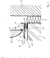
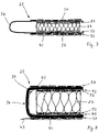
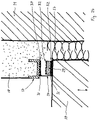
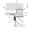
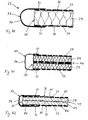
- a component 10 for example a door or window frame (in 1 shown schematically) is inserted into a wall opening of a wall 11 and connected to the wall 11.
- a joint 12 between the peripheral side 13 of the component 10 and the wall 11 at the soffit is filled by means of a joint filling material 14, e.g. B. a filling foam filled.
- a profile connection strip 17 known per se is arranged as a connection to an outer covering layer applied to the wall 11 , for example a plaster layer 18 .
- the profile connecting strip 17 has an approximately U-shaped cross section with a fastening base 19 and a front plastering leg 20 and a rear plastering leg 21 .
- the profile connection strip 17 is connected to the outside 16 of the component 10 by means of a sealing device 22, which is also referred to as a sealing strip unit, so that the sealing device 22 forms or contains a supporting body 29 between the component 10 and the fastening base 19 of the profile connection strip 17.
- a joint 23 extending between the profile connection strip 17 and the component 10 is thus filled and sealed by the sealing device 22 attached in a sealing manner.
- the profile connecting strip 17 Before the plaster layer 18 is applied to the wall 11, the profile connecting strip 17 is fixed in a stable position to the component 10 by means of the sealing device 22 in its intended position, which is to be maintained during plastering.
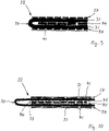
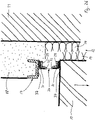
- the profile connecting strip 17 has, for example, a tab 24 that is known per se (see FIG 2 ), which can be separated from the profile connection strip 17 at a material weakening 25 after plastering and on which a protective film 26 covering the component 10 or the window is glued by means of an adhesive layer 27 .
- the Sealing device 22 holds the profile terminal strip 17 in a substantially stable position against a deforming force (shown schematically with arrow F 1 ), z. B. is generated by the weight of the profile terminal strip 17 and the protective film 26 and in particular by a wind load against the protective film 26 or can be.
- the front plaster leg 20 serves as a plastering aid for a plastering tool 28 (see 2 ) that presses with a force F 2 against the plaster leg 20 of the profile connection strip 17.
- the sealing device 22 holds the profile connection strip 17 in its position against this applied deformation force F 2 of the usual magnitude.
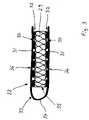
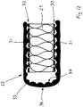
- the sealing device 22 is according to a first embodiment (see the enlarged view in accordance with 3 ) is constructed essentially in layers and contains a foam strip 29 as the central layer or inner support layer, on the two opposite surfaces 30 of which a sealing tape strip 31 is attached by means of an adhesive device 32 as part of the support body.
- the two sealing tape strips 31 are the spaced-apart edge strips of a sealing tape 33 which is folded in a U-shape and whose central section 34 forms a closed fold or bend as a joint cover in front of a narrow end face 35 of the foam strip 29, with end face 35 being laid according to the installation example in 1 and 2 referred to as the outer face 35 since it is directed away from the wall 11 outwards towards the exterior space 15.
- the sealing device 22 contains an adhesive device 37 on the outer surfaces 36 of the two sealing tape strips 31 (see 1 and 2 , in 3 not shown), by means of which the sealing device 22 is attached to the profile connection strip 17 and to the component 10 in a sealing manner.
- the sealing device 22 is arranged in such a way that the closed middle section 34 covers the joint 23 on the visible side. This ensures that the joint 23 is securely sealed by the sealing strip 33 , which forms a joint cover that is in particular flush with the outer surface of the front plaster leg 20 .
- the door or window frame and the wall 11 have different expansion or movement behavior due to their different technical characteristics. At the joint 11 are therefore preferably caused by a different expansion behavior z.
- the door or window frame and the wall 11 are sufficiently movably connected to each other. Due to its elastic properties, the sealing device 22 enables compensating movements between the component 10 and the profile connecting strip 17 or the plaster layer 18.
- the joint 23 is narrowed and the sealing device 22 is compressed, with the elastic foam strip 29 being squeezed and compressed.
- the fold-like central section 34 of the sealing strip 33 adapts to the squeezing movement by bulging out of the joint 23 and also forms a joint cover.
- the sealing effect of the sealing tape 33 or the sealing device 22 is retained, since the two sealing tape strips 31 do not detach from or from their adhesive attachments.
- the viewing interface has a uniform design. The appearance or the optical presentation is improved compared to the prior art and/or is flawless.
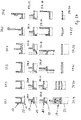
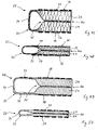
- the sealing device 22 is stressed by shearing forces, since the profile connecting strip 17 maintains its position on the plaster layer 18.
- the two outer adhesive devices 37 which hold the two sealing tape strips 31 on the profile connection strip 17 or the component 10, have a greater holding or adhesive force than the inner adhesive devices 32 between the two sealing tape strips 31 and the inner foam strip 29, so that the adhesive connection at least one of the two inner adhesive devices 32 tears open (in 21 the adhesive connections of the two adhesive devices 32 are shown torn open in a schematic representation). Consequently, the shifts Sealing tape strips 31 attached to the component 10 parallel to the sealing tape strips 31 attached to the profile connecting strip 17.
- the folded middle section 34 of the sealing tape 33 assumes an almost tensioned position, for example 21 and retains the sealing function and its function as a joint cover.
- the foam strip 29 will either remain on the profile connection strip 17 or it will be displaced with the component 10 .
- the viewing surface or the visible surface is designed uniformly. The appearance or the optical presentation is improved compared to the prior art and/or is flawless.
- the sealing device 22 is also stressed by shearing forces, since the profile connecting strip 17 maintains its position on the plaster layer 18.
- the two outer adhesive devices 37 which hold the two sealing tape strips 31 on the profile connection strip 17 or the component 10, in turn have a greater holding or adhesive force than the inner adhesive devices 32 between the two sealing tape strips 31 and the inner foam strip 29, so that the Adhesive connection of at least one of the two inner adhesive devices 32 tears open (in 22 the adhesive connection 32 between the foam strip 29 and the sealing tape strip 31 fastened to the component 10 is shown torn open).
- the sealing tape strip 31 attached to the component 10 is shifted parallel to the sealing tape strip 31 attached to the profile connection strip 17 and the middle section 34 of the sealing tape 33 takes up the in 22 shown position and retains the sealing function or its function as a joint cover.
- the viewing surface or the visible surface is designed uniformly. The appearance or the optical presentation is improved compared to the prior art and/or is flawless.
- the sealing device 22 is subjected to tension perpendicular to the sealing tape strips 31. in the in 23 In the position shown, the middle section 34 of the sealing strip 33 is almost stretched compared to the originally bulged position and the movement reserve due to bending of the middle section 34 of the sealing strip 33 that has not been bonded is thus largely used up.
- the central portion 34 of the sealing tape 33 is essentially free of tension, is not stretched and forms a seam panel.
- the non-adhered middle section 34 of the sealing strip 33 is stretched at least somewhat over the joint 23 and its movement reserve is used up.
- the foam strip 29 on the adhesive device 32 has previously become detached from the sealing tape strip 31 attached to the profile connecting strip 17 .
- the sealing function of the sealing device 22 for the significantly widening joint 23 is retained.
- the sealing strip 33 is elastic and stretchable at least in its middle section 34 or detaches from a component in sections, the component 10 can also move further away from the profile connection strip 17, while the middle section 34 seals the joint 23 tightly and thus forms a joint cover.
- the viewing interface has a uniform design. The appearance or the optical presentation is improved compared to the prior art and/or is flawless.
- the sealing device 22 can also react in such a way that (see 25 ) the foam strip 29 or supporting body tears open over an area between the two sealing tape strips 31, since the adhesive forces of the two adhesive devices 32 are greater than the material strength of the foam strip 29.
- the adhesive forces of the adhesive devices 37 are preferably also greater than the adhesive forces of the adhesive devices 32 and/or greater than the material strength of the foam strip 29. If the middle section 34 of the sealing strip 33 is not elastic, the tensioned middle section 34 can have a correspondingly large expansion of the joint 23 cause at least one of the two sealing tape strips 31 to detach slightly from the component 10 and/or from the profile connecting strip 17 and thereby form a joint cover.
- a sealing device 22 with a suitable middle section 34 is selected according to the requirements for the possible widening of the joint 23 .
- the viewing interface has a uniform design. The visual presentation is improved and/or flawless compared to the prior art.
- the sealing device 22 reacts in such a way that the tensioned middle section 34 pulls the two sealing tape strips 31 from the component 10 and from the profile connecting strip 17 over a certain length against the adhesive force of the two adhesive devices 37 and thus forms a significantly widened joint cover.
- the sealing device 22 is matched to a maximum expansion path of the joint 23, so that the sealing of the joint 23 is retained.
- the viewing interface has a uniform design. The visual presentation is improved and/or flawless compared to the prior art.
- the sealing device 22 can have a position according to FIG 27 take in.
- the foam strip 29 has become detached from the sealing tape strip 31 attached to the component 10 at the adhesive device 32 and remains on the sealing tape strip 31 attached to the profile connecting strip 17.
- the middle section 34 of the sealing tape 33 is stretched and has moved about 10 to the adhesive device 37 on the component 10 half the width of the associated sealing tape strip 31 is released.
- the sealing of the extended joint 23 is retained and a visually appealing joint panel is formed.
- the viewing interface has a uniform design. the visual presentation is improved over the prior art and/or flawless.
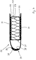
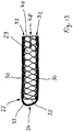
- a further modified embodiment contains the sealing device 22 two sealing tape strips 31, which in contrast to the example of 3 are not formed in one piece with one another, but rather overlap in a respective edge section 38 and are firmly and tightly connected to one another in the overlapping region by means of an adhesive bond 39 .
- a central section 34 of the sealing strip 33 formed from two individual sealing strip strips 31 in this embodiment is thus also formed as a closed fold or bulge in front of the lateral end face 35 of the foam strip 29 .
- the movement behavior of this sealing device 22 corresponds to the exemplary embodiment described above.
- the two sealing tape strips 31 can protrude beyond the foam strip 29 on the inner end face 40 of the foam strip 29 opposite the outer end face 35 .
- the outer gluing devices 37 are not shown. These can, for example, also only be applied during the processing of the sealing device 22 .
- a sealing device 22 can also be produced in whole or in part at the installation site.
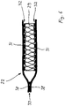
- a sealing tape 33 provided with an adhesive coating 32 on one side can be used, from which a protective film (not shown) covering the adhesive coating 32 is removed before it is folded in a V-shape.
- a foam strip 29 or other carrier body is placed between the two legs or sealing tape strips 31, which are then pressed against the foam strip 29 and glued to it by means of the adhesive devices 32 formed by the adhesive coating.
- the two front side protruding sealing tape strips 31 are firmly and tightly connected to each other in their edge portions 38, wherein in contrast to 4 the Inner sides of the two sealing tape strips 31 are connected to each other.
- the connection 39 can, for example, by means of an adhesive device or by welding the two sealing tape strips 31 z. B. done by heating or by adding welding material.
- the width of the overhang of the sealing tape strips 31 beyond the foam strips 29 and the width of their adhesion with the adhesive device 32 can be selected with regard to the required length of the middle section 34 of the sealing tape 33 to be formed.
- the adhesive-free middle section 34 is formed comparatively long and contains a large movement reserve.
- the two outer adhesive devices 37 extend beyond the foam strip 29 and are therefore longer or wider than the inner adhesive devices 32.
- the outer adhesive devices 37 have a greater adhesive force than the inner adhesive devices 32, so that when a movement of the sealing device 22 in the joint 23 the inner adhesive devices 32 will always come loose and the outer adhesive devices 37 will maintain the adhesion of the sealing tape strips 31 .
- the adhesive properties can also be different (see schematic representation).
- the according to 7 lower gluing device 37 is provided with a cover 41, e.g. B.
- the covering paper 41 preferably has different adhesive strengths on both sides and is in particular siliconized and accordingly provided with different adhesive qualities or adhesive forces that when the sealing device 22 is unwound or unwound, the covering paper 41 detaches itself from the next underlying layer while it is in its covering position of the outer gluing device 37 is retained.
- the sealing device 22 points towards that of 7 differently dimensioned components.
- the sealing tape strip 31 of the sealing tape 33 as well as the foam strip 29 are made thicker and they can have a reinforcement layer 42 such as. B. contain a glass fiber fabric, which is also called Scrim is referred to and which serves as an inner layer for a tensile force transmission at the central portion 34 when the sealing device 22 is deformed during movement in the joint 23.
- a cover film 41 of the lower outer adhesive device 37 has a free edge section 43 protruding beyond the adhesive device 37 in the area of the middle section 34, which is also referred to as a finger lift and is used for easier gripping of the cover film 41 when it is to be removed.
- the movement reserve is comparatively small here, as a result of which the overall shape of the sealing device 22 is given a more angular shape in the cross section shown, with a more planar arrangement of the central section 34 . This improves the visual appearance, especially when installed.
- the sealing device 22 according to 9 contains a thick sealing tape 33 folded in a U-shape with an intermediate layer 44 as the central connecting means in the form of a thick layer of adhesive instead of a foam strip.
- This sealing device 22 is almost incompressible.
- the middle section 34 has a small movement reserve.
- the adhesive force of the outer adhesive devices 37 is greater than that of the inner adhesive layer, so that when the sealing device 22 is deformed according to FIGS Figures 21 to 27 the connection between the two sealing tape strips 31 will loosen.
- the sealing device 22 according to 10 contains a thinner sealing tape 33 folded in a U-shape, which has a coating 45 on the insides of its two sealing tape strips 31, for example made of a fleece or fibers.
- An intermediate layer 44 as a central connecting device for example in the form of a strong adhesive layer, connects the two sealing tape strips 31 in the area of the two coatings 45.
- the coatings 45 determine the adhesive force and thus the forces that can be transmitted. As a result, the ratio of the forces can be set very reliably.
- the outer adhesive devices 37 are longer than the inner central adhesive layer 44 and, with otherwise identical conditions, have a lower, the same or higher adhesive force in comparison.
- the decisive factor here is the relationship to the adhesive force through the coatings 45. Due to the coatings 45, the external adhesive force is certainly higher than the internal adhesive force. Depending on the requirement, one or more identical or different coatings 45 can be arranged.
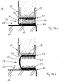
- the sealing device 22 according to 11 contains a U-shaped folded sealing tape 33 with two sealing tape strips 31, between which an intermediate layer 44 as a central connecting device in the form of a voluminous pasty sealant or adhesive 46, z. B. made of acrylic, silicone or PU adhesive, is arranged, which is adhesively connected to the two sealing tape strips 31.
- the initially pasty mass binds after some time and hardens in a product-specific manner and thus gives the sealing device 22 sufficient deformation stability in the assembled position, so that a profile connecting strip 17 is held in position before and during plastering.
- the mass 46 is also compressible over a certain distance if a deformation due to a movement of the component according to FIG 20 occurs.
- the mass 46 can adapt flexibly and elastically to the two sealing tape strips 31 that are moving away from one another. If, for example, mass 46 continues to harden after a longer installation time, mass 46 can tear off one of the two sealing tape strips 31, for example, while the outer adhesive devices 37 (not shown) hold sealing tape strips 31 firmly on component 10 or profile connection strip 17.
- the sealing device 22 contains a U-shaped folded sealing tape 33, the two sealing tape strips 31 are connected via a respective adhesive device 32 with a foam strip 29 as the inner support layer.
- the sealing strip 33 contains a surface structure 47 with elevations and depressions, so that the adhesive devices 32 essentially only have adhesive contact with the sealing strip strips 31 via the elevations. Due to the smaller adhesive surface, the adhesive strength is therefore lower compared to full-surface adhesion.
- the adhesive force of the adhesive device 32 is preferably lower than the adhesive force of the outer adhesive device 37 (not shown) for gluing the sealing tape strips 31 to the component 10 or the profile connecting strip 17.
- the elevations and depressions of the surface structure 47 can be formed, for example, in the manner of a knurled structure or as wavy elevations and depressions lying next to one another.
- the sealing device 22 contains a sealing tape 33 folded in a U-shape, the two sealing tape strips 31 of which are connected to the foam strip 29 via a respective adhesive device 32 .
- the foam strip 29 has a notch or slot 48 that extends inward from one narrow end face 40 of the foam strip 29 parallel to its surfaces 30 and weakens the foam material in such a way that when the sealing device 22 is deformed according to the invention, the foam strip 29 starts from the Slot 48 tears open as a predetermined breaking point and is divided into two parts over a large area (see 25 ).
- the two parts 29a and 29b of the foam strip 29 remained connected to the sealing tape strip 31 via the respective adhesive device 32 .
- the slot 48 can also be at the opposite (according to the 13 left) end face 35 can be provided and a slot 48 or generally a weakening or separating aid 49 can also be formed in each of the two end faces 35, 40.
- the sealing device 22 in turn contains a sealing tape 33 folded in a U-shape, the two sealing tape strips 31 of which are connected to the foam strip 29 via a respective adhesive device 32 .
- a tear cord 49 is provided, which is inserted between the sealing tape strip 31 and the foam strip 29 on the adhesive device 32, for example when the sealing tape strip 31 is glued on, and the gripping end of which protrudes laterally.
- three tear cords 49 are shown only schematically and by way of example in different installation positions.
- this adhesive device 32 is thus weakened, so that with an inventive Deformation of the sealing device 22, the entire adhesive connection of this adhesive device 32 is preferably separated.
- the lower center tear cord 49 separates a larger separating area 51 when pulled off to the right.
- the left-hand tear cord 49 is incorporated into the foam strip 29 in such a way that, when it is torn open, it at least partially or even completely separates the foam strip 29 into two halves or layers.
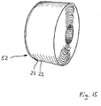
- the sealing device 22 wound up into a coil 52.
- the sealing device 22 can be e.g. B. be wound up in a length of 500 m to 4000 m.
- a cross-section through the coil layers is shown in 16 shown.
- the sealing device 22, z. B. according to 3 is formed, contains a U-shaped folded sealing tape 33, the two sealing tape strips 31 are connected via a respective adhesive device 32 with the foam strip 29.
- an adhesive device is provided on the upper side of the upper sealing tape strip 31, which contains a thin foam adhesive tape 53 and is covered with a covering film 54 on the upper side. Due to its thickness, this adhesive device provides the distance that is required so that the U-shaped middle section 34 of the sealing strip 33 cannot stick to the uncovered lower adhesive device 37 of the layer of the sealing device 22 lying above it (see double arrow).
- the cover film 54 contains surfaces with different adhesive strengths on both sides, e.g. B. is achieved by different siliconization of the surfaces.
- the lower adhesive device 37 is peeled away from the cover film 54 of the next underlying layer of the sealing device 22 to which it is adhesively resting and is ready for adhesion to a component.
- the cover film 54 must not become detached from the adhesive device on the upper sealing tape strip 31.
- FIG. 17 shows a sealing device 22, as z.
- Am 10 is shown in its installed position in a joint 23 between two components 10a and 10b.
- the two sealing tape strips 31 are on the one hand via a respective adhesive device 32 with the foam strip 29 and on the other hand connected via a respective adhesive device 37 with the component 10a and 10b.
- the middle section 34 of the sealing tape 33 is arranged on the visible side and merges almost directly into the two glued sealing tape strips 31 on both sides, so that there is little movement reserve before at least one of the sealing tape strips 31 is detached from its component 10a or 10b by a certain length.
- An adhesive device can be a sealing or adhesive compound, for example. This is particularly advantageous if a component has a mineral surface (eg plaster, paint or the like).
- the surface of the component can also have bumps and/or a powdery, sandy or dusty surface. Such surfaces are usually poorly suited for bonding with conventional adhesive tapes or foam adhesive tapes.
- a construction adhesive eg polyurethane adhesive
- a hybrid sealant can produce a sufficiently intensive connection here.
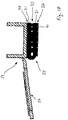
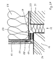
- connection strip 17 of an ETICS (thermal insulation composite system) shown which has a lip 55 on the visible side to cover a joint
- the sealing device 22 is glued on in such a way that the closed middle section 34 of the sealing strip 33 on the rear or inner side opposite the visible side in front of the inner front side 40 of the foam strip 29 is arranged.
- the joint 23 is thus sealed inside or behind the sealing device 22 or the foam strip 29 . Since the sealing device 22 is covered on the visible side by the lip 55 on its open and optically inferior end face 35, this arrangement can be selected.
- each sealing device 22 can be arranged in the installed state in such a way that the middle section 34 of the sealing strip 33 is on the inside with respect to the joint 23 and is therefore not visible to the eye. Also in this position a secure sealing of the joint 23 is guaranteed.
- a profile connection strip 17 has a rectangular cross-section with a component attachment leg 57 and a plastering leg 58 projecting upwards therefrom at right angles and to which a reinforcing fabric strip 59 is attached.
- a rigid cover leg 60 formed on the profile connection strip 17 covers the sealing device 22, which forms a sealing flexible connection between the profile connection strip 17 provides on the component 10 and the joint 23 seals in the manner already described.
- the covering leg 60 thus essentially covers the sealing device 22 .
- the visible part of the gap 23 or the sealing device 22 can be formed, for example, as a shadow gap.
- at least the middle section 34 of the sealing strip 33 should preferably be dark or black. In the case of relative movements in particular, the middle section 34 forms a visually appealing joint cover.
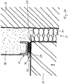
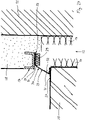
- a component 10 such. B. a window frame is fixed to a wall 11, wherein a joint 12 between the component 10 and the wall 11 is filled with joint filler 14. Above the joint 12 there is still an old layer of plaster 62 on the wall 11, which was limited in the area of the joint 12 by the old window frame previously located there. Since the component 10 is subsequently installed during the renovation, the thickness of the plaster layer 62 must also be taken into account when determining the size of the window frame 10, so that a comparatively wide joint 12 arises.
- the profile connection strip 17 is an angle profile with a component fastening leg 57 and a fixing leg 63.
- the profile connection strip 17 is fixed to the component 10 by means of a sealing device 22 via the component fastening leg 57 and is sealed thereto.
- a joint 64 between the fixing leg 63 and the plaster layer 62 is sealed with an adhesive sealing material 65 or a sealant or adhesive such as z. B. acrylic or silicone, which sets or hardens product-specifically after application and creates an essentially firm connection, so that when relative movements occur between the component 10 and the wall 11 or the plaster layer 62, the profile connection strip 17 on the wall 11 in the Is essentially or completely immovable and the movement compensation is preferably carried out via the sealing device 22. Therefore, the adhesive forces of the inner adhesive device 32 on the sealing device 22 (see e.g. 8 ) must not be greater than the adhesive forces of the adhesive sealing material 65 on the plaster layer 62.
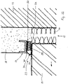
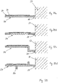
- FIG. 30 shows a horizontal cross-section of a sealing device 22 in a vertical joint, as z. B. is present between the thermal insulation layers 56 on the outer walls of two adjacent houses or semi-detached houses.
- This sealing device or profile strip is also suitable for horizontal joints.
- the sealing device 22 is arranged in the joint 23 between two profile strips 17 of an expansion joint profile and tightly fastened to a fastening base 19 of the associated profile strip 17 in each case by means of an external adhesive device 37 .
- Each profile strip 17 contains a plaster leg 58, which extends at right angles from the fastening base 19 and can have recesses 66 for plaster or filler material 61, which is applied to the thermal insulation layer 56 and to the profile strip 17 placed on the corner of the thermal insulation layer 56 when plastering the profile strip 17 .
- a reinforcing fabric strip 59 is also attached to the plaster leg 58 and is anchored in the filler material 61 .
- the fastening base 19 protrudes towards the outside of the wall beyond the plastering leg 58 and serves on its face 67 when plastering as a pull-off edge for a plastering tool. In the plastered installation state are thus the end faces 67 of the mounting bases 19 of the two profile strips 17 plan with the Surface 68 or outside of the spatula or plastering material 61 z.
- B. contains a finishing plaster layer.
- the sealing device 22 In the assembled state prior to installation, the sealing device 22 thus holds the two fastening bases 19 of the profile strips 17 parallel to one another in the space required for installation in the joint 23 which, for. B. may have a width of 6 to 10 mm, correct distance.
- the middle section 34 of the sealing device 22 is located approximately in a plane between the two end faces 67 of the fastening bases 19 and forms a joint panel.
- a removable protective film 69 can be glued to the end faces 67 of the fastening bases 19, which is removed after the profile strips 17 have been plastered.
- the adhesive force of the outer adhesive device 37 is set to be greater than the adhesive force of the inner adhesive device 32, so that when the two profile strips 17 move relative to each other, the support body or foam strip 29, for example, will detach from one of the two sealing tape strips 31, while the sealing tape strips 31 will be detached at least in a remaining section remain sealingly stuck to the mounting base 19 and thus ensure the tightness of the joint seal.
- 31 shows the sealing of an expansion joint 23 in an inside corner on two thermal insulation layers 56 which are arranged at right angles to one another and are spaced apart from one another at a distance of the joint 23.
- the joint sealing basically corresponds to the exemplary embodiment in FIG 30 , however, according to 31 left profile bar 17 modified in such a way that the plastering leg 58 is formed as a flat extension of the mounting base 19 and a short plaster strip 70 protrudes at right angles from the mounting base 19 and the plastering leg 58 .
- the central section 34 of the sealing strip 33 borders on the plaster strip 70 in the installed state, so that a gap-free and therefore visually appealing joint seal and joint cover is created.
- the sealing device 22 is located in the joint 23 and is firmly connected to the fastening base 19 of the profile connecting strip 17 on the one hand and to a base part 72 of the roller blind rail 71 on the other by means of the two sealing tape strips 31 and associated external adhesive devices 37 .
- the sealing device 22 is positioned in such a way that the middle section 34 of the sealing strip 33 is approximately at the same height as an outer leg 73 of the roller blind rail 71 and is adjacent to a plastering leg 58 which protrudes from the fastening base 19 at approximately a right angle.
- a strip-shaped tab 24 is formed on the plaster leg 58 via a weakened zone 25, extends over the outer leg 73 of the roller blind rail 71 and is supported on the leg 73 by means of a support rib 74.
- a protective film 26 is attached to the tab 24 by means of an adhesive layer 27, spans the entire window or frame 10 when plastered and is removed after plastering together with the tab 24, which is severed at the weakened zone 25.
- the roller blind rail 71 is arranged relative to the profile connecting strip 17 via the sealing device 22 in such a way that the surface 75 of its base part 72 is at a distance from the upper side 76 of the plaster leg 58 or the surface 68 of the plaster or filler layer 61 when the roller blind rail 71 z. B. is pivoted away from the window frame 10 when a belt of the roller blind needs to be repaired (in 32 from the component 10 vertically upwards past the plastering leg 58).
- the seal with the sealing device 22 can be partially or completely destroyed.
- a required subsequent sealing z. B. be made by a compriband or by applying a silicone strip to the space between the roller blind rail 71 and the plaster leg 58.
- Figure 33 shows a modification of the embodiment of FIG 32 , wherein the profile connecting strip 17 has a fastening base 19 and a plastering leg which is set back from the fastening base 19 and is preferably parallel to it 58 has.
- the surface of the mounting base 19 is in the installed position coplanar with the surface 68 of the plaster or putty layer 61.
- the middle section 34 of the sealing tape 33 sealingly arranged in the joint 23 covers the joint 23 approximately parallel to the outer leg 73 of the roller blind rail 71 and offers a flawless appearance.
- the base part 72 of the roller blind rail 71 has a greater distance from the surface 68 of the plaster or filler layer 61, the distance corresponding to the joint 23 in which the sealing device 22 is arranged in a sealing manner.
- the middle section 34 of the sealing strip 33 can follow this movement without destroying the sealing device 22 if there is a sufficiently large movement reserve.
- This movement reserve consists z. B. in the case when the central portion 34 as shown in FIG Figure 33 is not glued to the roller blind rail 71 and the profile connection strip 17 in a large area. If the roller blind rail 71 is removed by a distance that exceeds the movement reserve, the middle section 34 can first detach from its adhesive bond, so that the sealing device 22 remains functional even after the roller blind rail 71 has been installed in its original position. In addition, the sealing device 22 according to the embodiment of 32 destroyed and preferably subsequently sealed again. In any case, a displacement or pivoting of the roller blind rail 71 is possible.
- 34 12 shows an embodiment in which a sealing device 22 is arranged between a window frame 10 and a profile connecting strip 17 which has a U-shaped cross-section and receives a drywall panel 77 which is attached to a building surface or wall 11.
- the profile connecting strip 17 is attached to the wall 11 by means of a layer of adhesive or filler 78 .
- the sealing device 22, which basically corresponds to the exemplary embodiments described above, is about halfway on the window frame 10 glued and with the other half without adhesive connection with a component or in connection with the joint filling material 14.
- a sealing device 22 is fastened with its central section 34 of the sealing strip 33 flush between the component 10 and a front plaster leg 20 of a profile connection strip 17, with the surface 68 of the plaster layer 62 adjoining the profile connection strip 17 also running in this plane.
- This solution is also suitable, for example, for sealing joints in components that are flush with the facade, such as windows or doors.
- the Figures 36a and 36b show an embodiment of a sealing device 22 in its sealing arrangement between a component 10 and a profile terminal strip 17, wherein the 36a shows the sealing device 22 after the profile connection strip 17 has been installed or plastered in.
- the outer adhesive devices 37 hold the sealing tape strips 31 firmly on the component 10 or the plaster connecting strip 17 and leave the middle section 34 with a larger movement or deformation reserve.
- the distance between the profile connection bar 17 and the component 10 and thus the joint width of the joint 23 is z. B. 4 mm and the width of the adhesive layer of the outer adhesive means 37 is z. B. 7.5 mm with a width of the mounting base 19 of the profile terminal strip 17 of z. 10mm.
- the central section 34 is thus not glued on both sides in a non-adhesive area 79 of approximately 2.5 mm and is therefore free for a movement adjustment and deformation with the formation of a joint panel.
- Figure 36b shows the sealing device 22 away from the profile connection strip 17 after a relative movement of the component 10 .
- the supporting body or foam strip 29 is torn open and the middle section 34 has adapted to the widened joint 23 with a changed shape of a joint cover, in that its unglued sections resting on the component 10 or the profile connecting strip 17 have lifted off.
- the sealing tape strips 31 are still over the adhesive devices 37 firmly glued.
- the middle section 34 is slightly curved, there is still a small movement or deformation reserve for a further small expansion of the joint 23 Figure 36b
- the central section 34 first stretches and then the taut central section 34 will release the sealing tape strips 31 from their adhesion to the outer adhesive device 37 in accordance with the widening of the joint 23 when the tensile force that can be transmitted by the central section 34 is greater than the adhesive force of the outer adhesive devices 37.
- a profile strip 17 can have one or more plaster removal edges.
- a profile strip can have openings or punched-out sections or a reinforcing fabric section.
- a profile bar can be narrow or medium wide or wide.
- a profile strip can have a connecting device for plaster, spatula, tiles, sheet metal, adhesive or the like.
- a profile strip can be in one piece or in several pieces.
- a sealing device 22 can be arranged visibly or concealed on a profile strip.
- a sealing device 22 can be narrow or wide, thick or thin, transverse or elongated, rectangular or square in cross-section in relation to a profile strip 17 .
- 38 shows various adhesive devices and their detachability in a basic representation to explain the adhesive behavior (without sealing device).
- 38a shows a gluing device 80 such.
- B an adhesive tape or an adhesive coating in the installed state between two components 10 'and 10 ".
- Figures 38b and 38c show the two components 10 and 10' of FIG 38a after they move apart.
- the adhesive device 80 has completely detached from one of the components.
- the gluing device 80 has divided.
- Figure 38d shows a sealing or adhesive compound 81 in the installed state between two components 10' and 10".
- 38e and 38f show the condition after yourself have spaced the two components 10' and 10" apart.
- the adhesive compound 81 has completely detached itself from the one component 10'.
- the adhesive 81 has divided.
- 38g shows a foam adhesive tape 82 with two adhesive devices 83 in the installed state between two components 10' and 10".
- Fig. 38h and 38i show the position of the components 10' and 10" of 38g after they move apart.
- an adhesive device 83 has completely detached itself from one component 10'.
- the carrier material here for example the foam strip 82, has divided, while both adhesive devices 83 remain in adhesive connection.
- the carrier material can, for example, also be paper, cardboard, fleece, felt, fabric, fabric, foil or the like. Mixed forms or multi-layer combinations can also provide the desired properties.
- the adhesive devices can also be arranged in a mixed form.
- An adhesive coating is preferably an adhesive layer to be applied.
- the adhesive is applied, for example, from a container of a suitable device during manufacture of the sealing device.
- Adhesives are, for example, hot-melt adhesives or solvent-based adhesives or acrylate adhesives.
- Adhesive tapes usually provide a ready-to-use adhesive device with a defined dimension.
- Adhesive tapes are preferably provided as adhesive transfer tapes or as foam adhesive tapes. These are usually manufactured as rolls or spools and applied to an adhesive substrate by unwinding.
- a sealing or adhesive compound is mostly pasty during the manufacture of the adhesive device and sets after processing. After setting, the sealant or adhesive is often elastic. Household silicone, acrylic, polyurethane or hybrid sealants in cartridges belong to the sealants or adhesives.
- Figure 39 shows several cross-sectional views of different configurations of pull-off strips or tabs 24.
- a schematically illustrated profile strip 17 with a sealing device 22 according to the invention can have a known pull-off strip 24 in a preferred embodiment.
- a sealing device 22 (see figure 40 ) a foam strip as a supporting body 29, which has adhesive devices 37 on its two outer surfaces or surfaces 30 to be attached to components.
- a sealing tape 33 is bent in an approximately U-shape and covers the end face 35 of the foam tape 29 at a distance.
- the two sealing tape strips 31 on the edge each preferably only extend over a section of the outer or surface 30 and are sealed in this section with the adhesive device 37 glued.
- the sealing device 22 is thus fastened or bonded to the respective component via the adhesive device 37 that is not covered by the sealing tape 33.
- a section of the sealing tape strip 31 can also be bonded to a component.
- the sealing device 22 according to Figure 41 contains two foam tapes, foam strips or foam adhesive tapes 29 as the supporting body, which are connected to one another via a comparatively thick connecting or adhesive device 44 .
- the sealing strip 33 is with its central portion 34 compared to the embodiment of figure 40 closer to the end face 35 and, with this arrangement and design, has a smaller movement reserve, but a more angular shape.
- a separation of the supporting body 29 in the installed position in the event of a joint widening can preferably be carried out at the central connecting or adhesive device 44 .
- the sealing device 22 contains a supporting body 29 with a separation aid 49 in the form of a weakened zone, at which the supporting body 29 can tear open if necessary, as well as an outer adhesive device 37 on each of the two outer surfaces 30.
- the supporting body 29 is z. B. an extruded plastic soft material or foam material in which a plurality of slot-shaped cavities 84 are formed in a central plane, between which webs of material 85 the connect the two layers or halves of the supporting body 29 to one another in a simplified, detachable manner.
- the sealing tape 33 is glued with its sealing tape strips 31 on a larger section of the outer surfaces 30 of the support body 29 .
- sealing device 22 shown as a further exemplary embodiment contains a supporting body 29 which, for. B. made of extruded soft plastic, silicone foam or the like, and has a separating aid 49 in the form of a particularly eccentric weakened zone with slot-shaped cavities 84 formed therein.
- the sealing band 33 is formed integrally and of the same material with the supporting body 29 .
- the sealing strip 33 can be formed with a certain inherent stability and in front of the end face 35, for example, in a rectangular cross-section, so that its flat middle section 34 can cover a joint between two components flat and with a visually advantageous appearance as a joint cover.
- the transition 86 of the sealing strip 33 to the supporting body 29 is formed with increasing thickness in order to improve the stability or the arrangement of the sealing strip 33 .
- Adhesive devices 37 can be applied to the two outer surfaces 30 in the area of the supporting body 29 .
- the cross section of this sealing device 22 can preferably be in the range of about 8 times 4 mm to 20 times 10 mm, for example in the case of soffit connection profiles or in the case of expansion joint profiles for EIFS.
- sealing device 22 which is opposite to that of Figure 43 is designed for slimmer joints, also contains a support body 29, which is preferably made of an extruded soft material and on which the sealing strip 33 is integrally formed.
- the sealing tape 33 has a central portion 34 which is formed thicker in comparison to the sealing tape strip 31 so that it z. B. can contain a larger proportion of plasticizers, giving him the required flexibility and durability of the plastic material is retained over a longer period of use. This increases the weather resistance.
- a separation aid 49 is formed as a weakened zone in the center of the support body 29 by a plurality of cavities 84 .
- the adhesive device 37 can be on either of the two Outer surfaces 30 may be formed with different thicknesses, whereby different adhesive forces on or along the two outer surfaces 30 can be achieved even with otherwise identical adhesive materials.
- the sealing tape strips 31 can thus have a lower adhesive force than the supporting body 29 .
- the sealing device 22 shown contains an inner support layer 87 of the support body 29 made of a foam tape or foam adhesive tape.
- An extruded sealing tape 33 has a generally U-shaped central section 34 made of soft plastic material and coextruded sealing tape strips 31 forming part of the support body 29 .
- the sealing tape strips 31 are made of hard plastic material and are fixed to the outer surfaces 30 of the inner supporting layer 87 of the supporting body 29 by means of the adhesive devices 32 .
- the sealing tape 33 is also glued in sections to the inner support layer 87 at its two transition sections 88 to the sealing tape strips 31, as a result of which the softer sealing tape 33 is kept in shape.
- the sealing device 22 is formed from a sealing strip 33 which is extruded in a U-shape from soft plastic material and the two legs of which are connected to one another via an adhesive device as the central connecting device.
- the middle section 34 has a greater thickness at its end face for greater resistance or a greater proportion of plasticizers.
- the two adjoining leg sections are made thinner for better mobility and deformability.
- the adjoining sealing tape strips 31 are in turn made thicker and, although made of soft material, form the stable supporting body 29.
- One end section 89 of each sealing tape strip 31 is coextruded from hard material, giving the supporting body 29 greater stability here.
- the adhesive bond connecting the two sealing tape strips 31 consists, for. B.
- the end face 35 of the supporting body 29 covered by the sealing strip 33 is in this exemplary embodiment formed by the inner shoulders of the two sealing tape strips 31.
- the gluing device 37 at the according Figure 46 The upper outer surface 30 leaves a wider section towards the central section 34 of the sealing strip 33 free of adhesive compared to the lower outer surface 30, so that when the sealing device 22 is installed and the joint widens, the sealing strip 33 initially detaches predominantly on its upper side from its contact with the associated component, before one of the two outer adhesive bonds 37 is separated in sections.
- the sealing device 22 contains a supporting body 29 which is formed from two spaced edge sections of a foam strip which are placed against one another when the foam strip is folded and which are connected to one another by means of a central connecting device 44, for example an adhesive device.
- the central middle portion 34 of the sealing tape 33 is z. B. is compressed mechanically or by the action of heat and has a higher strength than the uncompacted foam material, whereas the comparatively thick edge sections are very compressible when the joint narrows during operation.
- the foam material is z. B. a PU foam, a polyolefin foam or a silicone foam.
- the thickening transition area from the middle section 34 of the sealing strip 33 to the supporting body 29 is not glued to a component, so that the easy mobility of the middle section 34 is retained.
- the sealing strip 33 or its middle section 34 can have a coating which can improve the sealing properties or the appearance of the sealing strip 33 .
- the sealing device according to the embodiment of Figure 48 differs from the sealing device of Figure 47 with a comparable manufacturing method essentially due to the changed design and the changed dimensions.
- the sealing strip 33 which adapts to movements, is comparatively thin and less resistant to deformation.
- the two outer adhesive devices 37 therefore extend very far forward to the sealing tape 33 in order to stabilize it on the components.
- the two layers of the supporting body 29 can, for example, be welded by heat or they are connected to one another by an adhesive device 44 and can be attached to this connection tear open again.
- the two outer adhesive devices 37 can be formed for adhesive bonding to different component surfaces with different adhesiveness.
- the sealing device 22 according to Figure 49 is preferably extruded from plastic soft material.
- the two layers of the support body 29 are z. B. connected to each other by a weld or heating and fusing the material.
- the integrally formed adaptable sealing band 33 is formed so that it projects very far from the end face 35 of the support body 29 and thus has a large reserve of movement.
- the adhesive devices 37 on the outer surfaces 30 of the support body 29 extend very far forward to the middle section 34, the adhesive force being lower in the front adhesive area (represented by thinner lines).
- the thickness of the sealing strip 33 increases continuously at its transition to the supporting body 29 and thus has greater stability.
- the two adhesive devices 37 therefore do not have to reach as far as the deformation area of the sealing strip 33 .
- the two layers of the support body 29 are connected by means of a non-full-surface connecting device 44 z. B. connected to each other by gluing.
- Figure 51 shows a sealing device 22 in an installed position in a wedge-shaped or triangular in cross-section joint 23 between two components 10.
- the sealing device 22 is z. B. accordingly 11 constructed and can adapt to the desired wedge-shaped shape of the joint 23 between the two components 10 due to the flexible material of the support body 29 and the inner support layer.
- the portion of the sealing strip 33 of the sealing device 22 that is visible on the left side is very small when installed, which means that the appearance is an.
- Figure 52 shows a further sealing device 22 also in an installed position in a joint 23 which is wedge-shaped or trapezoidal in cross-section.
- the sealing device 22 is basically comparable to that of Figure 43 constructed, but is extruded in the illustrated wedge-shaped configuration with non-parallel outer surfaces 30.
- the outer adhesive devices 37 connect the supporting body 29 to the two components 10.
- the sealing strip 33 is adhesively bonded to its section adjoining the lower component, so that when the joint 23 widens, the section adjoining the upper component 10 follows the relative movement first.
- the sealing device 22 has a separating aid 49 .
- Figure 53 shows a sealing device 22 similar to the embodiment of FIG Figure 45 , However, the U-shaped sealing tape 33 with its two sealing tape strips 31, which are attached or glued as part of the support body 29 on the outer surfaces of the inner support layer, extruded in one piece from hard plastic.
- the section of the sealing strip 33 protruding beyond the end face 35 of the supporting body 29 contains two joints 91 or film hinges at the transitions to the bonded sealing strip strips 31 and two joints 92 or film hinges at the transitions between the central section 34 and the lateral sections. These joints 91 and 92 enable the relatively stiff sealing strip 33 to adapt its movement, in particular in the joints 91 and 92.
Landscapes
- Engineering & Computer Science (AREA)
- Architecture (AREA)
- Civil Engineering (AREA)
- Structural Engineering (AREA)
- Building Environments (AREA)
Applications Claiming Priority (2)
| Application Number | Priority Date | Filing Date | Title |
|---|---|---|---|
| DE202009002918U DE202009002918U1 (de) | 2009-03-02 | 2009-03-02 | Dichtvorrichtung zur Fugenabdichtung zwischen zwei Bauteilen |
| PCT/EP2010/001290 WO2010099936A2 (de) | 2009-03-02 | 2010-03-02 | Dichtvorrichtung zur fugenabdichtung zwischen zwei bauteilen |
Publications (2)
| Publication Number | Publication Date |
|---|---|
| EP2404010A2 EP2404010A2 (de) | 2012-01-11 |
| EP2404010B1 true EP2404010B1 (de) | 2022-06-29 |
Family
ID=42356931
Family Applications (5)
| Application Number | Title | Priority Date | Filing Date |
|---|---|---|---|
| EP10708117.6A Active EP2404010B1 (de) | 2009-03-02 | 2010-03-02 | Profilanschlussleiste mit einer dichtvorrichtung zur fugenabdichtung |
| EP20187867.5A Withdrawn EP3757311A1 (de) | 2009-03-02 | 2010-03-02 | Profilleiste mit einer dichtvorrichtung zur fugenabdichtung zwischen zwei bauteilen |
| EP10707469.2A Active EP2404008B1 (de) | 2009-03-02 | 2010-03-02 | Dichtanordnung an einer fuge an einem bauwerk |
| EP10707468.4A Active EP2404007B1 (de) | 2009-03-02 | 2010-03-02 | Profilleiste mit einer dichtvorrichtung zur fugenabdichtung zwischen zwei bauteilen |
| EP10708116.8A Active EP2404009B1 (de) | 2009-03-02 | 2010-03-02 | Profilanschlussleiste mit einer dichtvorrichtung zur fugenabdichtung |
Family Applications After (4)
| Application Number | Title | Priority Date | Filing Date |
|---|---|---|---|
| EP20187867.5A Withdrawn EP3757311A1 (de) | 2009-03-02 | 2010-03-02 | Profilleiste mit einer dichtvorrichtung zur fugenabdichtung zwischen zwei bauteilen |
| EP10707469.2A Active EP2404008B1 (de) | 2009-03-02 | 2010-03-02 | Dichtanordnung an einer fuge an einem bauwerk |
| EP10707468.4A Active EP2404007B1 (de) | 2009-03-02 | 2010-03-02 | Profilleiste mit einer dichtvorrichtung zur fugenabdichtung zwischen zwei bauteilen |
| EP10708116.8A Active EP2404009B1 (de) | 2009-03-02 | 2010-03-02 | Profilanschlussleiste mit einer dichtvorrichtung zur fugenabdichtung |
Country Status (5)
| Country | Link |
|---|---|
| EP (5) | EP2404010B1 (pl) |
| DE (1) | DE202009002918U1 (pl) |
| LT (1) | LT2404007T (pl) |
| PL (2) | PL2404008T3 (pl) |
| WO (4) | WO2010099933A1 (pl) |
Families Citing this family (15)
| Publication number | Priority date | Publication date | Assignee | Title |
|---|---|---|---|---|
| DK2415942T3 (da) | 2010-08-05 | 2013-05-27 | Iso Chemie Gmbh | Tætningsbånd |
| DE102010051274A1 (de) * | 2010-11-12 | 2012-05-16 | Jörg Krüger | Siliconband zum elastischen Verschließen von Fugen |
| EP2669459B1 (de) * | 2012-05-30 | 2016-08-10 | STO SE & Co. KGaA | Vorrichtung zum Schließen einer in einer Fassadenebene eines Gebäudes liegenden Dehnungsfuge |
| ITAN20130240A1 (it) * | 2013-12-12 | 2015-06-13 | Luigi Verdini | Profilo di partenza antimuffa per sistemi termoisolanti |
| EP2886739A1 (de) * | 2013-12-18 | 2015-06-24 | STO SE & Co. KGaA | Vorrichtung und Verfahren zur Ausbildung eines Anschlusses einer ein- oder mehrlagigen Putzschicht an eine Blechverwahrung |
| DE202018103502U1 (de) * | 2018-06-21 | 2018-10-25 | August Braun | Anputzleisten-Anordnung |
| DE102019125064A1 (de) * | 2019-09-18 | 2021-03-18 | Protektorwerk Florenz Maisch Gmbh & Co. Kg | Profilelement |
| AT523110A1 (de) | 2019-10-31 | 2021-05-15 | Mick Mag Christian | Anschlussprofilleiste |
| DE102019008630A1 (de) * | 2019-12-13 | 2021-06-17 | Mabo Steuerungselemente Gmbh | Schnittschutzbandeinrichtung, insbesondere für ein Wannendichtbad |
| US11732465B2 (en) * | 2020-05-19 | 2023-08-22 | Pre-Form Systems | System and method for modular construction |
| DE102020115799A1 (de) | 2020-06-16 | 2021-12-16 | Zahner Holding GmbH | Sockelputzleiste |
| DE102020120016A1 (de) | 2020-07-29 | 2022-02-03 | Zahner Holding GmbH | Putzprofilleiste |
| AT523847B1 (de) * | 2021-02-01 | 2021-12-15 | K Uni Kunststoffproduktions Und Handels Gmbh | Anschlussprofil für an putz angrenzende bauteile |
| DE102021134353A1 (de) * | 2021-12-22 | 2023-06-22 | Saint-Gobain Isover G+H Aktiengesellschaft | Selbstklebendes dichtungsband umfassend ein füllmaterial |
| AT527680B1 (de) | 2024-04-08 | 2025-05-15 | Mick Mag Christian | Anputzdichtleiste |
Family Cites Families (23)
| Publication number | Priority date | Publication date | Assignee | Title |
|---|---|---|---|---|
| US2071299A (en) * | 1933-12-22 | 1937-02-16 | John R Gammeter | Joint for roadways |
| SE213596C1 (sv) * | 1963-11-08 | 1967-06-13 | Trelleborgs Gummifabriks Ab | Förfaringssätt för täting av sprickor och fogar samt tätningsmembran för sättets genomförande |
| FR1446278A (fr) * | 1965-09-07 | 1966-07-15 | Servicised Ltd | Garniture d'étanchéité |
| CA1145131A (en) * | 1980-04-05 | 1983-04-26 | Hajime Yamaji | Aqueously-swelling water stopper and a process of stopping water thereby |
| DE3414180A1 (de) * | 1984-04-14 | 1985-10-24 | Georg Prinzing GmbH & Co KG Betonformen- und Maschinenfabrik, 7902 Blaubeuren | Dichtungseinrichtung fuer aneinanderstossende, zumindest etwa rohrfoermige bauteile, insbesondere fuer betonformteile |
| DE19616061C1 (de) * | 1996-04-23 | 1997-09-11 | Gima Gipser Und Malerbedarf Gm | Dehnfugenprofil |
| US6422575B1 (en) * | 2000-03-14 | 2002-07-23 | L&L Products, Inc. | Expandable pre-formed plug |
| AU2001242491A1 (en) * | 2000-03-20 | 2001-10-03 | Josef Klemens | Sealing and insulating system having a sealing and insulating profile |
| DE20114499U1 (de) * | 2001-09-03 | 2002-02-14 | Lorentz, Doris, 66333 Völklingen | Befestigung für Putzanschlußleisten |
| DE10317414A1 (de) | 2003-04-15 | 2004-11-25 | Lehrhuber, Konrad, Dipl.-Ing. (FH) | Profilanschlußleiste für einen Übergang von einem Bauteil zu einer Gebäudewand |
| DE10317443A1 (de) * | 2003-04-16 | 2004-11-04 | Illbruck Gmbh | Aufnahmeelement |
| AT6819U1 (de) | 2003-05-22 | 2004-04-26 | Peter Kassmannhuber | Laibungsanschlussprofil für an putz angrenzende bauteile |
| US20050102941A1 (en) * | 2003-11-04 | 2005-05-19 | E.M.E.H., Inc. | Fire barrier system for building panels |
| DE102004015556B4 (de) | 2004-03-30 | 2005-12-22 | August Braun | Putzanschlussleiste für Fensterrahmen oder dgl. mit Basisteil und Anputzteil |
| DE102004059522A1 (de) | 2004-12-09 | 2006-06-14 | Hanno-Werk Gmbh & Co. Kg | Klebendes Erzeugnis zur Abdichtung und/oder zum Anschluss von Materialien |
| DE202005020164U1 (de) * | 2005-12-23 | 2006-03-16 | Vws-Befestigungstechnik Gmbh | Bewegungsausgleichsprofil |
| DE102006002054A1 (de) | 2006-01-16 | 2007-07-19 | Konrad Lehrhuber | Abdichtungsanordnung und Profilleiste für eine Abdichtungsanordnung |
| AT504237B1 (de) * | 2006-10-11 | 2010-05-15 | Peter Kassmannhuber | Laibungsanschlussprofil für an putz angrenzende bauteile |
| EP1936246B2 (de) | 2006-12-18 | 2013-04-03 | ISO-Chemie GmbH | Dichtband aus Weichschaum und Verfahren zu seiner Herstellung |
| DE202007000895U1 (de) * | 2007-01-16 | 2007-04-12 | Lehrhuber Konrad | Profilanschlussleiste für einen Übergang von einem Bauteil zu einer Gebäudewand |
| DE202007001697U1 (de) * | 2007-02-06 | 2007-04-05 | Vws-Befestigungstechnik Gmbh | Anschlussprofil, insbesondere Putzanschlussprofil |
| DE102007009945A1 (de) * | 2007-03-01 | 2008-09-04 | Tremco Illbruck Produktion Gmbh | Anputzleiste für Blendrahmen |
| DE102007023431B4 (de) * | 2007-05-16 | 2012-07-26 | Roman Zahner | Anschlussprofilleiste, insbesondere Laibungsanschlussprofilleiste |
-
2009
- 2009-03-02 DE DE202009002918U patent/DE202009002918U1/de not_active Expired - Lifetime
-
2010
- 2010-03-02 WO PCT/EP2010/001287 patent/WO2010099933A1/de not_active Ceased
- 2010-03-02 WO PCT/EP2010/001290 patent/WO2010099936A2/de not_active Ceased
- 2010-03-02 WO PCT/EP2010/001289 patent/WO2010099935A1/de not_active Ceased
- 2010-03-02 PL PL10707469T patent/PL2404008T3/pl unknown
- 2010-03-02 PL PL10707468T patent/PL2404007T3/pl unknown
- 2010-03-02 EP EP10708117.6A patent/EP2404010B1/de active Active
- 2010-03-02 EP EP20187867.5A patent/EP3757311A1/de not_active Withdrawn
- 2010-03-02 WO PCT/EP2010/001288 patent/WO2010099934A1/de not_active Ceased
- 2010-03-02 EP EP10707469.2A patent/EP2404008B1/de active Active
- 2010-03-02 LT LTEP10707468.4T patent/LT2404007T/lt unknown
- 2010-03-02 EP EP10707468.4A patent/EP2404007B1/de active Active
- 2010-03-02 EP EP10708116.8A patent/EP2404009B1/de active Active
Also Published As
| Publication number | Publication date |
|---|---|
| EP3757311A1 (de) | 2020-12-30 |
| EP2404008A1 (de) | 2012-01-11 |
| DE202009002918U1 (de) | 2010-07-22 |
| WO2010099933A1 (de) | 2010-09-10 |
| WO2010099935A1 (de) | 2010-09-10 |
| EP2404010A2 (de) | 2012-01-11 |
| PL2404007T3 (pl) | 2021-03-08 |
| WO2010099936A2 (de) | 2010-09-10 |
| EP2404008B1 (de) | 2021-05-26 |
| EP2404007B1 (de) | 2020-07-29 |
| WO2010099934A1 (de) | 2010-09-10 |
| PL2404008T3 (pl) | 2021-10-04 |
| EP2404007A1 (de) | 2012-01-11 |
| WO2010099936A3 (de) | 2010-12-09 |
| EP2404009A1 (de) | 2012-01-11 |
| EP2404009B1 (de) | 2021-12-08 |
| LT2404007T (lt) | 2020-12-10 |
Similar Documents
| Publication | Publication Date | Title |
|---|---|---|
| EP2404010B1 (de) | Profilanschlussleiste mit einer dichtvorrichtung zur fugenabdichtung | |
| EP1507950B1 (de) | Dichtungsband | |
| EP1808565B1 (de) | Abdichtungsanordnung und Profilleiste für eine Abdichtungsanordnung | |
| DE102007010997A1 (de) | Fugenband für Sanitäreinrichtungen | |
| EP1947280B1 (de) | Profilanschlussleiste für einen übergang von einem bauteil zu einer gebäudewand | |
| DE10255598B4 (de) | Selbstklebendes Dichtungsband | |
| EP3372133B1 (de) | Dicht- und montageband-anordnung | |
| DE10310326B4 (de) | Eckstück zur Verwendung mit einem Dichtungsband zum Abdichten von Anschlussfugen zwischen einem Fensterrahmen und einer Fensterlaibung eines Bauwerks | |
| EP1722064B1 (de) | Anschlussprofilleiste, insbesondere Laibungsanschlussprofilleiste | |
| AT501439B1 (de) | Laibungsanschlussprofil für an putz und an eine dämmschicht angrenzende bauteile | |
| EP1707727A2 (de) | Abdichtungsanordnung und Verfahren zum Herstellen einer Abdichtung | |
| EP1741867A1 (de) | Dichteinrichtung | |
| DE10333823A1 (de) | Abdichtende Folienbahn, Fensterrahmen mit einer solchen Bahn und Verwendung dieser Bahn | |
| EP4194638B1 (de) | Anputzdichtleiste | |
| DE202009013120U1 (de) | Einteilige Anputzleiste sowie Übergang zwischen zwei Bestandteilen eines Gebäudes | |
| DE202005004044U1 (de) | Foliensystem zur Abdichtung von Anschlussfugen | |
| EP3473782A1 (de) | Anschlussprofil für an putz angrenzende bauteile | |
| DE102023105542A1 (de) | Anputzdichtleiste | |
| DE29716477U1 (de) | Dichtband | |
| EP1676014A1 (de) | Knickfolienbahn für den baubereich | |
| EP1795687A1 (de) | Dichteinrichtung | |
| EP1835116A1 (de) | Leiste |
Legal Events
| Date | Code | Title | Description |
|---|---|---|---|
| PUAI | Public reference made under article 153(3) epc to a published international application that has entered the european phase |
Free format text: ORIGINAL CODE: 0009012 |
|
| 17P | Request for examination filed |
Effective date: 20110831 |
|
| AK | Designated contracting states |
Kind code of ref document: A2 Designated state(s): AT BE BG CH CY CZ DE DK EE ES FI FR GB GR HR HU IE IS IT LI LT LU LV MC MK MT NL NO PL PT RO SE SI SK SM TR |
|
| DAX | Request for extension of the european patent (deleted) | ||
| 17Q | First examination report despatched |
Effective date: 20150227 |
|
| STAA | Information on the status of an ep patent application or granted ep patent |
Free format text: STATUS: EXAMINATION IS IN PROGRESS |
|
| GRAP | Despatch of communication of intention to grant a patent |
Free format text: ORIGINAL CODE: EPIDOSNIGR1 |
|
| STAA | Information on the status of an ep patent application or granted ep patent |
Free format text: STATUS: GRANT OF PATENT IS INTENDED |
|
| RAP3 | Party data changed (applicant data changed or rights of an application transferred) |
Owner name: LEHRHUBER, KONRAD |
|
| RIN1 | Information on inventor provided before grant (corrected) |
Inventor name: LEHRHUBER, KONRAD |
|
| INTG | Intention to grant announced |
Effective date: 20220128 |
|
| GRAS | Grant fee paid |
Free format text: ORIGINAL CODE: EPIDOSNIGR3 |
|
| GRAA | (expected) grant |
Free format text: ORIGINAL CODE: 0009210 |
|
| STAA | Information on the status of an ep patent application or granted ep patent |
Free format text: STATUS: THE PATENT HAS BEEN GRANTED |
|
| AK | Designated contracting states |
Kind code of ref document: B1 Designated state(s): AT BE BG CH CY CZ DE DK EE ES FI FR GB GR HR HU IE IS IT LI LT LU LV MC MK MT NL NO PL PT RO SE SI SK SM TR |
|
| REG | Reference to a national code |
Ref country code: GB Ref legal event code: FG4D Free format text: NOT ENGLISH |
|
| REG | Reference to a national code |
Ref country code: CH Ref legal event code: EP |
|
| REG | Reference to a national code |
Ref country code: DE Ref legal event code: R096 Ref document number: 502010017005 Country of ref document: DE |
|
| REG | Reference to a national code |
Ref country code: AT Ref legal event code: REF Ref document number: 1501455 Country of ref document: AT Kind code of ref document: T Effective date: 20220715 |
|
| REG | Reference to a national code |
Ref country code: IE Ref legal event code: FG4D Free format text: LANGUAGE OF EP DOCUMENT: GERMAN |
|
| REG | Reference to a national code |
Ref country code: LT Ref legal event code: MG9D |
|
| PG25 | Lapsed in a contracting state [announced via postgrant information from national office to epo] |
Ref country code: SE Free format text: LAPSE BECAUSE OF FAILURE TO SUBMIT A TRANSLATION OF THE DESCRIPTION OR TO PAY THE FEE WITHIN THE PRESCRIBED TIME-LIMIT Effective date: 20220629 Ref country code: NO Free format text: LAPSE BECAUSE OF FAILURE TO SUBMIT A TRANSLATION OF THE DESCRIPTION OR TO PAY THE FEE WITHIN THE PRESCRIBED TIME-LIMIT Effective date: 20220929 Ref country code: LT Free format text: LAPSE BECAUSE OF FAILURE TO SUBMIT A TRANSLATION OF THE DESCRIPTION OR TO PAY THE FEE WITHIN THE PRESCRIBED TIME-LIMIT Effective date: 20220629 Ref country code: HR Free format text: LAPSE BECAUSE OF FAILURE TO SUBMIT A TRANSLATION OF THE DESCRIPTION OR TO PAY THE FEE WITHIN THE PRESCRIBED TIME-LIMIT Effective date: 20220629 Ref country code: GR Free format text: LAPSE BECAUSE OF FAILURE TO SUBMIT A TRANSLATION OF THE DESCRIPTION OR TO PAY THE FEE WITHIN THE PRESCRIBED TIME-LIMIT Effective date: 20220930 Ref country code: FI Free format text: LAPSE BECAUSE OF FAILURE TO SUBMIT A TRANSLATION OF THE DESCRIPTION OR TO PAY THE FEE WITHIN THE PRESCRIBED TIME-LIMIT Effective date: 20220629 Ref country code: BG Free format text: LAPSE BECAUSE OF FAILURE TO SUBMIT A TRANSLATION OF THE DESCRIPTION OR TO PAY THE FEE WITHIN THE PRESCRIBED TIME-LIMIT Effective date: 20220929 |
|
| REG | Reference to a national code |
Ref country code: NL Ref legal event code: MP Effective date: 20220629 |
|
| PG25 | Lapsed in a contracting state [announced via postgrant information from national office to epo] |
Ref country code: LV Free format text: LAPSE BECAUSE OF FAILURE TO SUBMIT A TRANSLATION OF THE DESCRIPTION OR TO PAY THE FEE WITHIN THE PRESCRIBED TIME-LIMIT Effective date: 20220629 |
|
| PG25 | Lapsed in a contracting state [announced via postgrant information from national office to epo] |
Ref country code: NL Free format text: LAPSE BECAUSE OF FAILURE TO SUBMIT A TRANSLATION OF THE DESCRIPTION OR TO PAY THE FEE WITHIN THE PRESCRIBED TIME-LIMIT Effective date: 20220629 |
|
| PG25 | Lapsed in a contracting state [announced via postgrant information from national office to epo] |
Ref country code: SM Free format text: LAPSE BECAUSE OF FAILURE TO SUBMIT A TRANSLATION OF THE DESCRIPTION OR TO PAY THE FEE WITHIN THE PRESCRIBED TIME-LIMIT Effective date: 20220629 Ref country code: SK Free format text: LAPSE BECAUSE OF FAILURE TO SUBMIT A TRANSLATION OF THE DESCRIPTION OR TO PAY THE FEE WITHIN THE PRESCRIBED TIME-LIMIT Effective date: 20220629 Ref country code: RO Free format text: LAPSE BECAUSE OF FAILURE TO SUBMIT A TRANSLATION OF THE DESCRIPTION OR TO PAY THE FEE WITHIN THE PRESCRIBED TIME-LIMIT Effective date: 20220629 Ref country code: PT Free format text: LAPSE BECAUSE OF FAILURE TO SUBMIT A TRANSLATION OF THE DESCRIPTION OR TO PAY THE FEE WITHIN THE PRESCRIBED TIME-LIMIT Effective date: 20221031 Ref country code: ES Free format text: LAPSE BECAUSE OF FAILURE TO SUBMIT A TRANSLATION OF THE DESCRIPTION OR TO PAY THE FEE WITHIN THE PRESCRIBED TIME-LIMIT Effective date: 20220629 Ref country code: EE Free format text: LAPSE BECAUSE OF FAILURE TO SUBMIT A TRANSLATION OF THE DESCRIPTION OR TO PAY THE FEE WITHIN THE PRESCRIBED TIME-LIMIT Effective date: 20220629 |
|
| REG | Reference to a national code |
Ref country code: DE Ref legal event code: R082 Ref document number: 502010017005 Country of ref document: DE Representative=s name: KILIAN KILIAN & PARTNER MBB PATENTANWAELTE, DE |
|
| PG25 | Lapsed in a contracting state [announced via postgrant information from national office to epo] |
Ref country code: PL Free format text: LAPSE BECAUSE OF FAILURE TO SUBMIT A TRANSLATION OF THE DESCRIPTION OR TO PAY THE FEE WITHIN THE PRESCRIBED TIME-LIMIT Effective date: 20220629 Ref country code: IS Free format text: LAPSE BECAUSE OF FAILURE TO SUBMIT A TRANSLATION OF THE DESCRIPTION OR TO PAY THE FEE WITHIN THE PRESCRIBED TIME-LIMIT Effective date: 20221029 |
|
| REG | Reference to a national code |
Ref country code: DE Ref legal event code: R097 Ref document number: 502010017005 Country of ref document: DE |
|
| PG25 | Lapsed in a contracting state [announced via postgrant information from national office to epo] |
Ref country code: DK Free format text: LAPSE BECAUSE OF FAILURE TO SUBMIT A TRANSLATION OF THE DESCRIPTION OR TO PAY THE FEE WITHIN THE PRESCRIBED TIME-LIMIT Effective date: 20220629 Ref country code: CZ Free format text: LAPSE BECAUSE OF FAILURE TO SUBMIT A TRANSLATION OF THE DESCRIPTION OR TO PAY THE FEE WITHIN THE PRESCRIBED TIME-LIMIT Effective date: 20220629 |
|
| PLBE | No opposition filed within time limit |
Free format text: ORIGINAL CODE: 0009261 |
|
| STAA | Information on the status of an ep patent application or granted ep patent |
Free format text: STATUS: NO OPPOSITION FILED WITHIN TIME LIMIT |
|
| 26N | No opposition filed |
Effective date: 20230330 |
|
| PG25 | Lapsed in a contracting state [announced via postgrant information from national office to epo] |
Ref country code: SI Free format text: LAPSE BECAUSE OF FAILURE TO SUBMIT A TRANSLATION OF THE DESCRIPTION OR TO PAY THE FEE WITHIN THE PRESCRIBED TIME-LIMIT Effective date: 20220629 |
|
| PG25 | Lapsed in a contracting state [announced via postgrant information from national office to epo] |
Ref country code: MC Free format text: LAPSE BECAUSE OF FAILURE TO SUBMIT A TRANSLATION OF THE DESCRIPTION OR TO PAY THE FEE WITHIN THE PRESCRIBED TIME-LIMIT Effective date: 20220629 |
|
| REG | Reference to a national code |
Ref country code: CH Ref legal event code: PL |
|
| GBPC | Gb: european patent ceased through non-payment of renewal fee |
Effective date: 20230302 |
|
| REG | Reference to a national code |
Ref country code: BE Ref legal event code: MM Effective date: 20230331 |
|
| PG25 | Lapsed in a contracting state [announced via postgrant information from national office to epo] |
Ref country code: LU Free format text: LAPSE BECAUSE OF NON-PAYMENT OF DUE FEES Effective date: 20230302 |
|
| REG | Reference to a national code |
Ref country code: IE Ref legal event code: MM4A |
|
| PG25 | Lapsed in a contracting state [announced via postgrant information from national office to epo] |
Ref country code: GB Free format text: LAPSE BECAUSE OF NON-PAYMENT OF DUE FEES Effective date: 20230302 |
|
| PG25 | Lapsed in a contracting state [announced via postgrant information from national office to epo] |
Ref country code: LI Free format text: LAPSE BECAUSE OF NON-PAYMENT OF DUE FEES Effective date: 20230331 Ref country code: IT Free format text: LAPSE BECAUSE OF FAILURE TO SUBMIT A TRANSLATION OF THE DESCRIPTION OR TO PAY THE FEE WITHIN THE PRESCRIBED TIME-LIMIT Effective date: 20220629 Ref country code: IE Free format text: LAPSE BECAUSE OF NON-PAYMENT OF DUE FEES Effective date: 20230302 Ref country code: GB Free format text: LAPSE BECAUSE OF NON-PAYMENT OF DUE FEES Effective date: 20230302 Ref country code: FR Free format text: LAPSE BECAUSE OF NON-PAYMENT OF DUE FEES Effective date: 20230331 Ref country code: CH Free format text: LAPSE BECAUSE OF NON-PAYMENT OF DUE FEES Effective date: 20230331 |
|
| PG25 | Lapsed in a contracting state [announced via postgrant information from national office to epo] |
Ref country code: BE Free format text: LAPSE BECAUSE OF NON-PAYMENT OF DUE FEES Effective date: 20230331 |
|
| PG25 | Lapsed in a contracting state [announced via postgrant information from national office to epo] |
Ref country code: BG Free format text: LAPSE BECAUSE OF FAILURE TO SUBMIT A TRANSLATION OF THE DESCRIPTION OR TO PAY THE FEE WITHIN THE PRESCRIBED TIME-LIMIT Effective date: 20220629 |
|
| PG25 | Lapsed in a contracting state [announced via postgrant information from national office to epo] |
Ref country code: BG Free format text: LAPSE BECAUSE OF FAILURE TO SUBMIT A TRANSLATION OF THE DESCRIPTION OR TO PAY THE FEE WITHIN THE PRESCRIBED TIME-LIMIT Effective date: 20220629 |
|
| PGFP | Annual fee paid to national office [announced via postgrant information from national office to epo] |
Ref country code: DE Payment date: 20250321 Year of fee payment: 16 |
|
| PGFP | Annual fee paid to national office [announced via postgrant information from national office to epo] |
Ref country code: AT Payment date: 20250319 Year of fee payment: 16 |
|
| PG25 | Lapsed in a contracting state [announced via postgrant information from national office to epo] |
Ref country code: CY Free format text: LAPSE BECAUSE OF FAILURE TO SUBMIT A TRANSLATION OF THE DESCRIPTION OR TO PAY THE FEE WITHIN THE PRESCRIBED TIME-LIMIT; INVALID AB INITIO Effective date: 20100302 |
|
| PG25 | Lapsed in a contracting state [announced via postgrant information from national office to epo] |
Ref country code: HU Free format text: LAPSE BECAUSE OF FAILURE TO SUBMIT A TRANSLATION OF THE DESCRIPTION OR TO PAY THE FEE WITHIN THE PRESCRIBED TIME-LIMIT; INVALID AB INITIO Effective date: 20100302 |
|
| PG25 | Lapsed in a contracting state [announced via postgrant information from national office to epo] |
Ref country code: TR Free format text: LAPSE BECAUSE OF FAILURE TO SUBMIT A TRANSLATION OF THE DESCRIPTION OR TO PAY THE FEE WITHIN THE PRESCRIBED TIME-LIMIT Effective date: 20220629 |