EP1936246B2 - Dichtband aus Weichschaum und Verfahren zu seiner Herstellung - Google Patents
Dichtband aus Weichschaum und Verfahren zu seiner Herstellung Download PDFInfo
- Publication number
- EP1936246B2 EP1936246B2 EP20060026192 EP06026192A EP1936246B2 EP 1936246 B2 EP1936246 B2 EP 1936246B2 EP 20060026192 EP20060026192 EP 20060026192 EP 06026192 A EP06026192 A EP 06026192A EP 1936246 B2 EP1936246 B2 EP 1936246B2
- Authority
- EP
- European Patent Office
- Prior art keywords
- tape
- film
- flexible foam
- sealing
- sealing tape
- Prior art date
- Legal status (The legal status is an assumption and is not a legal conclusion. Google has not performed a legal analysis and makes no representation as to the accuracy of the status listed.)
- Active
Links
Images
Classifications
-
- F—MECHANICAL ENGINEERING; LIGHTING; HEATING; WEAPONS; BLASTING
- F16—ENGINEERING ELEMENTS AND UNITS; GENERAL MEASURES FOR PRODUCING AND MAINTAINING EFFECTIVE FUNCTIONING OF MACHINES OR INSTALLATIONS; THERMAL INSULATION IN GENERAL
- F16J—PISTONS; CYLINDERS; SEALINGS
- F16J15/00—Sealings
- F16J15/02—Sealings between relatively-stationary surfaces
- F16J15/021—Sealings between relatively-stationary surfaces with elastic packing
- F16J15/022—Sealings between relatively-stationary surfaces with elastic packing characterised by structure or material
-
- E—FIXED CONSTRUCTIONS
- E04—BUILDING
- E04B—GENERAL BUILDING CONSTRUCTIONS; WALLS, e.g. PARTITIONS; ROOFS; FLOORS; CEILINGS; INSULATION OR OTHER PROTECTION OF BUILDINGS
- E04B1/00—Constructions in general; Structures which are not restricted either to walls, e.g. partitions, or floors or ceilings or roofs
- E04B1/62—Insulation or other protection; Elements or use of specified material therefor
- E04B1/66—Sealings
- E04B1/68—Sealings of joints, e.g. expansion joints
- E04B1/6812—Compressable seals of solid form
-
- E—FIXED CONSTRUCTIONS
- E06—DOORS, WINDOWS, SHUTTERS, OR ROLLER BLINDS IN GENERAL; LADDERS
- E06B—FIXED OR MOVABLE CLOSURES FOR OPENINGS IN BUILDINGS, VEHICLES, FENCES OR LIKE ENCLOSURES IN GENERAL, e.g. DOORS, WINDOWS, BLINDS, GATES
- E06B1/00—Border constructions of openings in walls, floors, or ceilings; Frames to be rigidly mounted in such openings
- E06B1/62—Tightening or covering joints between the border of openings and the frame or between contiguous frames
-
- E—FIXED CONSTRUCTIONS
- E06—DOORS, WINDOWS, SHUTTERS, OR ROLLER BLINDS IN GENERAL; LADDERS
- E06B—FIXED OR MOVABLE CLOSURES FOR OPENINGS IN BUILDINGS, VEHICLES, FENCES OR LIKE ENCLOSURES IN GENERAL, e.g. DOORS, WINDOWS, BLINDS, GATES
- E06B7/00—Special arrangements or measures in connection with doors or windows
- E06B7/16—Sealing arrangements on wings or parts co-operating with the wings
- E06B7/22—Sealing arrangements on wings or parts co-operating with the wings by means of elastic edgings, e.g. elastic rubber tubes; by means of resilient edgings, e.g. felt or plush strips, resilient metal strips
- E06B7/23—Plastic, sponge rubber, or like strips or tubes
-
- F—MECHANICAL ENGINEERING; LIGHTING; HEATING; WEAPONS; BLASTING
- F16—ENGINEERING ELEMENTS AND UNITS; GENERAL MEASURES FOR PRODUCING AND MAINTAINING EFFECTIVE FUNCTIONING OF MACHINES OR INSTALLATIONS; THERMAL INSULATION IN GENERAL
- F16J—PISTONS; CYLINDERS; SEALINGS
- F16J15/00—Sealings
- F16J15/02—Sealings between relatively-stationary surfaces
- F16J15/06—Sealings between relatively-stationary surfaces with solid packing compressed between sealing surfaces
- F16J15/068—Sealings between relatively-stationary surfaces with solid packing compressed between sealing surfaces the packing swelling under working conditions
-
- E—FIXED CONSTRUCTIONS
- E06—DOORS, WINDOWS, SHUTTERS, OR ROLLER BLINDS IN GENERAL; LADDERS
- E06B—FIXED OR MOVABLE CLOSURES FOR OPENINGS IN BUILDINGS, VEHICLES, FENCES OR LIKE ENCLOSURES IN GENERAL, e.g. DOORS, WINDOWS, BLINDS, GATES
- E06B1/00—Border constructions of openings in walls, floors, or ceilings; Frames to be rigidly mounted in such openings
- E06B1/62—Tightening or covering joints between the border of openings and the frame or between contiguous frames
- E06B2001/626—Tightening or covering joints between the border of openings and the frame or between contiguous frames comprising expanding foam strips
-
- Y—GENERAL TAGGING OF NEW TECHNOLOGICAL DEVELOPMENTS; GENERAL TAGGING OF CROSS-SECTIONAL TECHNOLOGIES SPANNING OVER SEVERAL SECTIONS OF THE IPC; TECHNICAL SUBJECTS COVERED BY FORMER USPC CROSS-REFERENCE ART COLLECTIONS [XRACs] AND DIGESTS
- Y10—TECHNICAL SUBJECTS COVERED BY FORMER USPC
- Y10T—TECHNICAL SUBJECTS COVERED BY FORMER US CLASSIFICATION
- Y10T156/00—Adhesive bonding and miscellaneous chemical manufacture
- Y10T156/10—Methods of surface bonding and/or assembly therefor
- Y10T156/1052—Methods of surface bonding and/or assembly therefor with cutting, punching, tearing or severing
-
- Y—GENERAL TAGGING OF NEW TECHNOLOGICAL DEVELOPMENTS; GENERAL TAGGING OF CROSS-SECTIONAL TECHNOLOGIES SPANNING OVER SEVERAL SECTIONS OF THE IPC; TECHNICAL SUBJECTS COVERED BY FORMER USPC CROSS-REFERENCE ART COLLECTIONS [XRACs] AND DIGESTS
- Y10—TECHNICAL SUBJECTS COVERED BY FORMER USPC
- Y10T—TECHNICAL SUBJECTS COVERED BY FORMER US CLASSIFICATION
- Y10T428/00—Stock material or miscellaneous articles
- Y10T428/14—Layer or component removable to expose adhesive
-
- Y—GENERAL TAGGING OF NEW TECHNOLOGICAL DEVELOPMENTS; GENERAL TAGGING OF CROSS-SECTIONAL TECHNOLOGIES SPANNING OVER SEVERAL SECTIONS OF THE IPC; TECHNICAL SUBJECTS COVERED BY FORMER USPC CROSS-REFERENCE ART COLLECTIONS [XRACs] AND DIGESTS
- Y10—TECHNICAL SUBJECTS COVERED BY FORMER USPC
- Y10T—TECHNICAL SUBJECTS COVERED BY FORMER US CLASSIFICATION
- Y10T428/00—Stock material or miscellaneous articles
- Y10T428/24—Structurally defined web or sheet [e.g., overall dimension, etc.]
- Y10T428/2419—Fold at edge
-
- Y—GENERAL TAGGING OF NEW TECHNOLOGICAL DEVELOPMENTS; GENERAL TAGGING OF CROSS-SECTIONAL TECHNOLOGIES SPANNING OVER SEVERAL SECTIONS OF THE IPC; TECHNICAL SUBJECTS COVERED BY FORMER USPC CROSS-REFERENCE ART COLLECTIONS [XRACs] AND DIGESTS
- Y10—TECHNICAL SUBJECTS COVERED BY FORMER USPC
- Y10T—TECHNICAL SUBJECTS COVERED BY FORMER US CLASSIFICATION
- Y10T428/00—Stock material or miscellaneous articles
- Y10T428/24—Structurally defined web or sheet [e.g., overall dimension, etc.]
- Y10T428/24273—Structurally defined web or sheet [e.g., overall dimension, etc.] including aperture
- Y10T428/24322—Composite web or sheet
- Y10T428/24331—Composite web or sheet including nonapertured component
-
- Y—GENERAL TAGGING OF NEW TECHNOLOGICAL DEVELOPMENTS; GENERAL TAGGING OF CROSS-SECTIONAL TECHNOLOGIES SPANNING OVER SEVERAL SECTIONS OF THE IPC; TECHNICAL SUBJECTS COVERED BY FORMER USPC CROSS-REFERENCE ART COLLECTIONS [XRACs] AND DIGESTS
- Y10—TECHNICAL SUBJECTS COVERED BY FORMER USPC
- Y10T—TECHNICAL SUBJECTS COVERED BY FORMER US CLASSIFICATION
- Y10T428/00—Stock material or miscellaneous articles
- Y10T428/24—Structurally defined web or sheet [e.g., overall dimension, etc.]
- Y10T428/24479—Structurally defined web or sheet [e.g., overall dimension, etc.] including variation in thickness
- Y10T428/24496—Foamed or cellular component
-
- Y—GENERAL TAGGING OF NEW TECHNOLOGICAL DEVELOPMENTS; GENERAL TAGGING OF CROSS-SECTIONAL TECHNOLOGIES SPANNING OVER SEVERAL SECTIONS OF THE IPC; TECHNICAL SUBJECTS COVERED BY FORMER USPC CROSS-REFERENCE ART COLLECTIONS [XRACs] AND DIGESTS
- Y10—TECHNICAL SUBJECTS COVERED BY FORMER USPC
- Y10T—TECHNICAL SUBJECTS COVERED BY FORMER US CLASSIFICATION
- Y10T428/00—Stock material or miscellaneous articles
- Y10T428/24—Structurally defined web or sheet [e.g., overall dimension, etc.]
- Y10T428/24777—Edge feature
-
- Y—GENERAL TAGGING OF NEW TECHNOLOGICAL DEVELOPMENTS; GENERAL TAGGING OF CROSS-SECTIONAL TECHNOLOGIES SPANNING OVER SEVERAL SECTIONS OF THE IPC; TECHNICAL SUBJECTS COVERED BY FORMER USPC CROSS-REFERENCE ART COLLECTIONS [XRACs] AND DIGESTS
- Y10—TECHNICAL SUBJECTS COVERED BY FORMER USPC
- Y10T—TECHNICAL SUBJECTS COVERED BY FORMER US CLASSIFICATION
- Y10T428/00—Stock material or miscellaneous articles
- Y10T428/249921—Web or sheet containing structurally defined element or component
- Y10T428/249953—Composite having voids in a component [e.g., porous, cellular, etc.]
- Y10T428/249982—With component specified as adhesive or bonding agent
- Y10T428/249983—As outermost component
Definitions
- the invention relates to a sealing strip made of soft foam.
- Sealing tapes made of soft and flexible foam material are used in structural engineering for sealing against draft and driving rain.
- foam tapes of usually a few millimeters thick, which are provided on one side with a self-adhesive layer covered by a release film and are wound uncompressed on rollers. They are used for sealing leaking windows and doors between window or door leaf and window or door frame. For this purpose, they are glued at the appropriate place on the wing or on the frame.
- sealing strips which are mostly impregnated, are made of soft and flexible foam between window and door frames and masonry.
- Such sealing tapes can be up to a few centimeters thick and are usually provided on one side with a self-adhesive layer, with which they can be adhered to the frame profile elements of windows and doors.
- Sealing tapes of this type are often impregnated with a material that retards the recovery of the foam material from a compressed state in which they are delivered to roll in a relaxed state to facilitate the assembly of the provided with the sealing tape component on site.
- Out DE 196 41 415 C2 is a sealing tape made of open-pored material in rolled-up to a disc shape for sealing joints or gaps against draft and / or driving rain is known in which at least one barrier layer within the sealing strip is arranged in such a configuration that they and the adjacent open-pore regions in the axial direction lined up. The barrier layer thus extends in the radial direction of the sealing tape roll.
- large-area barrier layers are formed by layer-by-layer lamination and / or bonding of plate or web of an open-pored raw foam material into laminate blocks.
- the laminate blocks are then separated into sheets with barrier layers orthogonal to the large-area barrier layers of lamination material and / or adhesive such that after separation the barrier layers extend parallel to an edge of the panel and perpendicularly through the panel.
- Such a sheet is then wound into a roll under compression so that the barrier layers and the open-pore material are lined up on the circumference of the roll in the axial direction.
- the roll is then sliced between individual barrier layers. This procedure is relatively complicated and requires a high dimensional stability of the foam material during processing, otherwise there is a risk of damaging the barrier layers when separating the roll into slices.
- the WO 98/45565 shows a sealing tape with a removable film coating, which covers the sealing tape in a compressed state on three sides.
- the invention has for its object to provide a finished with a foil strip sealing tape that can be easily produced, and to provide methods and apparatus for its production.
- compressed and uncompressed supplied sealing strips made of soft and flexible foam material can be distinguished.
- the invention can be applied almost equally for both forms of delivery.
- the film strip When compressed supplied sealing tapes, the film strip is attached with at least one edge strip on the underside of the foam tape, which is usually intended to glue the sealing tape to a component to be sealed, such as the frame profile element of a window or door.
- This side of the foam tape is provided with a self-adhesive layer, which then also holds the foil strip.
- the film strip is wide enough, even in the installed state of the device in which the foam tape, which is the main component of the sealing strip, is partially relaxed, completely on the adjacent side edge of the adjacent To extend sealing tape.
- the film strip may be so wide that it extends over one of the broad sides in the compressed state, over the two side edges and over edge strips of the foam tape.
- the sealing tape according to the invention can take on the same function as in DE 196 41 415 C2 described sealing tape.
- the film strip may also be a UV barrier film, which is to protect the foam material covered by it against UV light. Even films that are selected from an aesthetic point of view, such as metallized or colored films, are conceivable.
- the invention can be practiced with any type of film-like, pliable sheet material selected according to individual needs, including textile materials or multi-layer laminates.
- a significant advantage of the sealing tape according to the invention is that a fully movable system is provided, consisting of a soft, elastic foam tape and a film strip, wherein the film strip is connected to the foam tape so that it can move over the entire functional area of the sealing strip.
- the sealing strip according to the invention is in the form of narrow sealing tape rolls, called because of their dimensions also sealing tape discs produced without the need for a special preparation of the foam material in the production of sealing tape, which differs from the usual, is required. On the contrary, it provides for such sealing tape disks to be retrofitted with a pliable film, for example a vapor barrier film, in the form of a film web.
- a pliable film for example a vapor barrier film
- sealing tape usually a broad soft foam web, which may be impregnated with an expansion retarding agent, on one side with a cover, such as silicone paper, covered.
- a cover such as silicone paper
- a self-adhesive layer will be applied to the foam material.
- the thus prepared foam sheet is optionally rolled up under mechanical pressure reducing the thickness of the foam sheet and secured, for example by gluing the end of the outermost sealing tape layer to the underlying sealing tape layer, for example by means of an adhesive strip.
- the thus formed, compressed or uncompressed foam roller is then separated into slices of a predetermined width, for example by sawing. From this best practice, the invention makes identical use. But there are special steps to follow.
- the connection between the self-adhesive layer and the covering film is progressively mechanically released within the sealing tape, for example with the aid of a plow-shaped shoe moving with respect to the sealing tape, and a slack film strip, for example a vapor barrier film strip, is inserted into the gap created thereby and attached to the self-adhesive layer exposed by the gap formation. Subsequently, the gap closes again by the provision of the foam material, as soon as the shoe has moved away.
- the film strip protruding from the sealing tape pane still has a remaining width, which preferably corresponds to the sum of the thickness of a foam layer in the compressed state and the width of the sealing strip disk.
- the foam tape may, after assembly of the component equipped with it, relax a maximum of the width of the sealing tape without the complete covering of the one side face thereof being lost by the film tape.
- This foil strip is now continuously applied to the sealing tape and inserted between the foam layer, with which the relevant section of the film strip is glued, and the adhesive on the adjacent foam layer release film, again for example with the aid of a plow-shaped shoe. But it is also possible to make the remaining width of the film strip larger and, for example, to put on the other side of the sealing tape or to insert in longitudinal folds between the turns of the sealing tape.
- the sealing tape has a starting height of the foam tape of 30 mm and is compressed in the winding to a height of 4 - 5 mm, then its area of use is often by the manufacturer to a certain gap width, e.g. limited by 15 mm, which is to be bridged by the sealing tape. Because you do not let the foam material relax further, so that it rests firmly against the building wall. In practice, the functional range of such a sealing tape is thus between 4 and 15 mm.
- the functional range of the sealing strip which determines the film width to be selected, is thus determined by the compression extent of the foam material within the coil and the maximum return of the Foam material determined after assembly of the device equipped therewith.
- the minimum thickness after compression of impregnated foams is currently about 10% of the original thickness. The recovery after compression sometimes does not reach the original thickness anymore.
- the film strip is attached to the flexible foam tape with only an edge strip, it can be pushed through to the other side of the sealing tape with sufficient width of the film strip and folded over with its other edge strip on the same side of the flexible foam tape to which the first edge strip is attached, there but not pinned, but placed on the tack-free side of the cover.
- the foil tape over the full width to the self-adhesive layer, if present, and to project it on both sides of the sealing tape, then to place both projecting portions around the turn of the foam tape at which the respective length portion of the foil tape is attached.
- either the film strip in the region in which it covers the adhesive layer must be provided with sufficiently large openings or holes so that the adhesive layer remains effectively accessible from the outside. This is necessary on the one hand to hold the cover film, and on the other hand, to allow for the peel-off of the cover, the self-adhesive mounting on the component to be sealed.
- the finished sealing disc is thus covered on at least one side by a foil strip, which winds like the worm material like a snail.
- the adhering of the film strip to the foam tape and the subsequent insertion of the sealing tape from the projecting film strip between the turns of the sealing tape is done in a single operation.
- the sealing tape is rewound comparable to the rewinding of an audio tape.
- the sealing tape is thus unwound from the sealing tape and immediately rewound onto a second bobbin.
- the foam material of the sealing tape is already compressed, it is kept in a compressed state in the interval between unwinding and rewinding, whether by mechanical means or by expansion of the foam material sufficient to expand it.
- the covering film is detached from the self-adhesive layer covered by it at least over part of its width, a partial width of a film strip of the desired type is inserted and tacked into the gap thus formed, and the gap is subsequently closed again.
- sealing strip roll or disc is thus each sheet material between the cover of the one turn and the foam material of the adjacent turn of the sealing strip.
- the width of the film strip is chosen as in the procedure described in the first place.
- an uncompressed sealing tape can also be processed, which is compressed prior to re-winding, along with the foil strip finishing, to yield a compressed sealing tape.
- the self-adhesive layer can be applied to the foam tape, either as an adhesive mass or as a two-sided adhesive tape, with subsequent coverage by the aforementioned cover sheet. It is also possible to use a film strip, which is provided on its outer side with a self-adhesive layer and a cover this covering film. In this case, located on the first roll, foam tape need not be provided with a cover.
- a first advantageous device for equipping a soft foam sealing strip of rectangular cross section in the aforementioned type with a film strip comprises a turntable for placing the sealing tape, a device for holding the sealing tape on the turntable in a centered on the axis of rotation thereof, at least one above the turntable on a Carrier attached, plow-shaped shoe having a drainage edge and a rear side, means for moving the carrier in the radial direction relative to the turntable, means for feeding the film strip to the shoe from the back thereof, means for lowering the carrier in the direction the turntable and means for rotating the turntable in the direction from the rear to the run-off edge of the shoe.
- the foil tape is fed from the back under the shoe, which has the shape of a plow or carving tool with a V-shaped cross-section.
- This shoe is lowered onto the sealing tape with its vertex protruding and between the self-adhesive layer and the introduced this covering cover a sealing tape layer, about 1 to 5 mm deep.
- a gap is formed, in which the shoe presses the film strip.
- the sealing tape is now rotated in the direction that the adhered by the shoe to the sealing tape foil strip is pulled past the trailing edge of the shoe and this away.
- the shoe then plows its course in pursuit of the turns of the sealing tape, comparable to the stylus of a traditional record game, following the turns of the sealing tape.
- the tracking can be done from outside to inside or from the inside to the outside, depending on the winding direction of the sealing strip.
- a second plow-shaped shoe is arranged on the carrier which holds the shoe, at a radial and angular distance offset, which surrounds the attached from the first shoe to the sealing tape foil tape on the sealing tape and immediately into the space between the already equipped winding layer and the adjacent, not yet equipped winding layer einschiebt.
- the second shoe should be kept radially adjustable relative to the first shoe in order to adapt the device different sealing strip thicknesses.
- the apparatus has two winding stands, one of which, the unwinding stand, is intended to receive a sealing tape to be processed, and the other, the winding stand, is intended to receive the winding body, on which the manner according to the invention fully finished sealing tape is to wind up, with the associated means for braking the first winding state and for driving the second winding state.
- a device is arranged with a shoe which is adapted to be inserted between the cover film and the self-adhesive layer at least in an edge region of the recirculated between the two winding stations foam material.
- a third winding stand is provided, which is provided for receiving a foil tape reel. Guide means for feeding a film strip from the third winding stand to said shoe extend between the third winding stand and the shoe. Between the shoe and the second winding stand are means for turning the film strip on the free surfaces of the foam tape.
- a sealing strip is to be processed whose foam material is not impregnated with a material delaying its recovery
- there are devices in the intermediate space between the first and second winding stations which are suitable for carrying out the sealing strip unwound from the first winding station in the compressed state in which it leaves the first winding state. This is necessary to ensure that the foil tape can be transferred to the exposed top of the foam material.
- a wide, soft elastic foam web is laminated on at least one side with a film web.
- the thus-equipped foam sheet is wound into a roll and then cut into individual slices of a width corresponding to the height of a sealing strip in the uncompressed state thereof.
- the foam discs thus produced are then unwound, and the foam tape is then wound under rotation by 90 ° and under compression again to a sealing disc in which the covered by the at least one foil side edge of the sealing strip forms a flat side of the sealing band disc.
- one of the surfaces of the foam tape adjacent to a film-covered side may be provided with a self-adhesive tape and a release film covering it.
- Smooth tapes can be used as foil tapes. It is also possible to use foil tapes which are provided with longitudinally extending folds at least in a partial region of their width. This has the advantage that even with a very wide recovery of the compressed flexible foam tape after assembly of the sealing strip, the total width of the film strip is sufficient to completely cover a side surface of the foam tape.
- the pleats may optionally be provided with a delayed-release adhesive, thereby making it possible to retard the recovery of the foam material from the compressed state even when the foam material is not impregnated with a recovery-retarding material.
- a further variant provides for the use of a foil strip which forms a longitudinal pocket on a partial region of its width.
- This bag is intended to lie after relaxing the sealing tape on one of the visible sides of the foam tape may be filled with a material of desired quality, for example with an intumescent material.
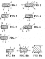
- FIG. 1 one recognizes a foam tape 1 that is shown in the compressed state. It has in the state shown a flat, rectangular cross-section and is provided on its one side, which is to be referred to here and in all the examples explained below as the bottom, with a self-adhesive layer 2, which is shown in dashed lines.
- a film strip 3 is attached by means of the self-adhesive layer 2, which is considerably wider than the foam tape 1.
- the over the width of the foam tape 1 outgoing side strips of the film strip 3 are wrapped around the foam tape 1 and overlap on the top of the Foam Tape 1.
- the film tape 3 is provided with a plurality of apertures or holes.
- the film strip 3 is covered by a cover 4.
- the breakthroughs or holes in the film strip 3 are sufficiently large that adherence of the covering film 4 achieves adhesion thereof through holes in the film strip 3 on the self-adhesive layer 2.
- FIG. 2 shows an embodiment of the invention in which a self-adhesive layer 2 on one side provided foam tape 1 is covered by a film strip 3, one edge between the self-adhesive layer 2 and an adhesive on the self-adhesive layer 2 cover 4 are inserted and is held by the self-adhesive layer 2 and the other edge of which lies on the covering film 4 and is held in the winding (not shown) between the separating film 4 and the foam tape 1 of the adjacent winding (not shown).
- the film strip 3 has in the region of the side edges 1a of the foam tape 1 a Aufgehreserve in the form of loose folds 3a, which can be realized by only a single fold or bulging of the film strip 3. If the foam tape 1 from the in Fig. 2 shown state rises, the film strip 3 on the in Fig. 2 slip right side edge 1a of the foam tape 1 and allows a total of an extremely strong rising of the foam tape 1, without the in Fig. 2 left side edge 1a of the same uncovered
- FIG. 3 shows a third embodiment of the invention, in which a film strip 3 is inserted at one edge of the underside of a foam tape 1 between a located on the underside of the foam tape 1 self-adhesive layer 2 and the edge of this covering cover 4.
- the film strip 3 is led up to a side edge 1a of the foam tape 1 and placed over the top thereof.
- FIG. 4 shows a modification of the embodiment of FIG. 3 , which differs from the latter in that on both sides of the foam tape 1 foil tapes 3 are attached to the self-adhesive layer 2 and covered by the edges of the cover 4. The two film strips 3 are wrapped around the foam tape 1 and overlap each other at the top.
- FIG. 5 shows a second variant of the embodiment of FIG. 3 , This differs from the embodiment according to FIG. 3 in that a longitudinal pocket 3b is formed on the foil strip 3, which can be filled with a material of predetermined quality, for example an intumescent material.
- a material of predetermined quality for example an intumescent material.
- this embodiment agrees with the FIG. 3 match.
- the embodiment according to FIG. 5 also in the sense of FIG. 4 can be modified, namely that two film strips 3 are provided, of which only one or both with a pocket 3b after FIG. 5 can be equipped.
- FIG. 6 shows a third variant of the embodiment from FIG. 3 ,
- the film strip 3 forms on the side edge 1a of the foam tape 1, a series of folds 3a, which allow the foam strip 1 when relaxing reaches a greater height than in the embodiment of FIG. 3 Without the side edge 1a remains uncovered by the film strip 3.
- This embodiment can again in the sense of the embodiment of FIG. 4 be symmetrical.
- the folds 3a can also be arranged on the upper side of the sealing strip like a loop (not shown in the drawing).
- the part of the fold 3a which touches the upper side of the sealing strip, there be selectively fixed or flat (eg glued), wherein the remaining part of the fold 3a forms the Aufgehreserve and is released upon expansion of the foam 1.
- FIG. 7 is a variant of the embodiment of FIG. 6 , It differs from the latter in that the pleats 3a are adhered internally to a retarding adhesive that allows the foam tape 1 to relax to a greater extent, but does so only at a speed determined by said adhesive.
- FIGS. 8a to 8c show the operation of a sealing tape according to the invention, wherein here as an example of the explanation here after that FIG. 3 is used.
- FIG. 8a shows the state of the sealing tape on the roll, but without representing the role. This state, the sealing tape also takes a directly after it has been released from the role, if the foam tape 1 is impregnated with a delaying its recovery impregnation. In the further course, the foam tape 1 then stands in the direction of the arrow A due to the elastic restoring force inherent in the foam material. This has the consequence that the film strip 3 slips over the upper edge, which connects the covered of the film strip 3 side edge 1a with the top of the foam tape 1. This movement is in FIG. 8b marked with the arrow B.
- the film strip 3 is almost completely slipped from the top of the foam tape 1 and still covers the entire side edge 1a of the foam tape 1.
- This condition exists, for example, when a equipped with the sealing tape frame component inserted into a building opening and is sealed by the sealing tape on the soffit of the building opening. It should be emphasized, however, that then the cover 4 is peeled off, since the sealing tape is adhered using the self-adhesive layer 2 to the respective frame component.
Landscapes
- Engineering & Computer Science (AREA)
- General Engineering & Computer Science (AREA)
- Structural Engineering (AREA)
- Civil Engineering (AREA)
- Architecture (AREA)
- Mechanical Engineering (AREA)
- Physics & Mathematics (AREA)
- Electromagnetism (AREA)
- Gasket Seals (AREA)
- Adhesive Tapes (AREA)
- Decoration Of Textiles (AREA)
- Sealing Material Composition (AREA)
- Laminated Bodies (AREA)
- Insulation, Fastening Of Motor, Generator Windings (AREA)
- Lining Or Joining Of Plastics Or The Like (AREA)
Description
- Die Erfindung betrifft ein Dichtband aus weichem Schaumstoff.
- Dichtbänder aus weichem und flexiblen Schaumstoffmaterial werden in der Bautechnik zum Abdichten gegen Luftzug und Schlagregen eingesetzt. Für den Hausgebrauch durch den Endverbraucher gibt es die allgemein bekannten Schaumstoffbänder von in der Regel wenigen Millimetern Dicke, die einseitig mit einer von einer Trennfolie abgedeckten Selbstklebeschicht versehen sind und unkomprimiert auf Rollen gewickelt sind. Sie werden für die Abdichtung undicht gewordener Fenster und Türen zwischen Fenster- bzw. Türflügel und Fenster- bzw. Türrahmen eingesetzt. Hierzu werden sie an passender Stelle am Flügel oder am Rahmen angeklebt.
- Im professionellen Hochbau werden Dichtbänder, die zumeist imprägniert sind, aus weichem und flexiblem Schaumstoff zwischen Fenster- und Türrahmen und einem Mauerwerk eingesetzt. Solche Dichtbänder können bis zu einigen Zentimetern dick sein und sind gewöhnlich einseitig mit einer Selbstklebeschicht versehen, mit der sie an den Rahmenprofilelementen von Fenstern und Türen angeklebt werden können. Dichtbänder dieser Art sind häufig mit einem Material imprägniert, das die Rückstellung des Schaumstoffmaterials aus einem komprimierten Zustand, in dem sie auf Rolle angeliefert werden, in einen entspannten Zustand verzögert, um die Montage des mit dem Dichtband versehenen Bauelements auf der Baustelle zu erleichtern.
- Zur Verhinderung einer Dampfdiffusion werden Dichtbänder der vorgenannten Art benötigt, die mit einer Dampfsperre versehen sind. Aus
DE 196 41 415 C2 ist ein Dichtband aus offenporigem Material in zu einer Scheibe aufgerollter Form zum Abdichten von Fugen oder Spalten gegen Luftzug und/oder Schlagregen bekannt, bei dem wenigstens eine Sperrschicht innerhalb des Dichtbandes in solcher Konfiguration angeordnet ist, dass sie und die angrenzenden offenporigen Bereiche in axialer Richtung aufgereiht sind. Die Sperrschicht verläuft also in radialer Richtung der Dichtbandrolle. - Um ein Dichtband der letztgenannten Art herzustellen, werden großflächige Sperrschichten durch lagenweises Laminieren und/oder Verkleben von Platten- oder Bahnware eines offenporigen Rohschaummaterials zu Laminatblöcken ausgebildet. Die Laminatblöcke werden dann orthogonal zu den großflächigen Sperrschichten aus Laminierungsmaterial und/oder Klebstoff zu Tafeln mit Sperrschichten getrennt, so dass sich nach dem Trennen die Sperrschichten parallel zu einem Rand der Tafel und senkrecht durch die Tafel erstrecken. Eine solche Tafel wird dann unter Kompression zu einer Rolle so aufgewickelt, dass die Sperrschichten und das offenporige Material auf dem Umfang der Rolle in axialer Richtung aufgereiht sind. Anschließen wird die Rolle zwischen einzelnen Sperrschichten in Scheiben getrennt. Diese Verfahrensweise ist relativ kompliziert und erfordert eine hohe Maßhaltigkeit des Schaumstoffmaterials bei der Verarbeitung, weil sonst beim Trennen der Rolle in Scheiben die Gefahr einer Beschädigung der Sperrschichten besteht.
- Aus
DE 24 57 322 A1 ist ein Verfahren bekannt, mit dem Kunststoffkörper aus offenporigem Schaumstoff an ihren Außenflächen durch Aufsprühen mit einem Polyurethanüberzug versehen werden können. Allerdings verlangt das Verfahren eine spezielle Vorbereitung des Schaumstoffs. Es ist nicht dafür geeignet, bei komprimierten Schaumstoffkörpern, die sich im Gebrauch entspannen sollen, angewendet zu werden, da der im komprimierten Zustand aufgebrachte Überzug das Entspannen behindern oder gar ganz unmöglich machen würde. Würde nur ein dünner Überzug aufgebracht, der das Entspannen des Schaumstoffs ermöglicht, bestünde die Gefahr einer Rissbildung im Überzug. Das Aufbringen des Überzugs durch Aufsprühen im entspannten Zustand ist bei Dichtbändern aus technischen Gründen unwirtschaftlich. - Die
WO 98/45565 - Der Erfindung liegt die Aufgabe zugrunde, ein mit einem Folienband ausgerüstetes Dichtband, das sich einfach herstellen lässt, sowie Verfahren und Vorrichtungen zu dessen Herstellung anzugeben.
- Diese Aufgabe wird hinsichtlich des Dichtbandes durch die in Anspruch 1 angegebene Erfindung gelöst. Verfahren und Vorrichtungen zum Herstellen des Dichtbandes sind Gegenstand weiterer Ansprüche. Vorteilhafte Ausgestaltungen der Erfindung sind Gegenstand der jeweils abhängigen Ansprüche.
- Grundsätzlich lassen sich komprimiert und unkomprimiert gelieferte Dichtbänder aus weichem und flexiblem Schaumstoffmaterial unterscheiden. Die Erfindung lässt sich grundsätzlich bei beiden Lieferformen nahezu gleichermassen anwenden.
- Bei komprimiert gelieferten Dichtbändern ist das Folienband mit wenigstens einem Randstreifen an der Unterseite des Schaumstoffbandes angeheftet, die üblicherweise dafür vorgesehen ist, das Dichtband an einem abzudichtenden Bauelement, etwa am Rahmenprofilelement eines Fensters oder einer Tür, anzukleben. Diese Seite des Schaumstoffbandes ist mit einer Selbstklebeschicht versehen, die dann auch das Folienband festhält.
- Das Folienband ist breit genug, sich auch im eingebauten Zustand des Bauelements, in dem das Schaumstoffband, das die Hauptkomponente des Dichtbandes bildet, teilentspannt ist, vollständig über die ihr benachbarte freiliegende Seitenflanke des Dichtbandes zu erstrecken. Gegebenenfalls kann das Folienband so breit sein, dass es sich über eine der im komprimierten Zustand breiten Seiten, über die beiden Seitenflanken und über Randstreifen des Schaumstoffbandes erstreckt.
- Als Folienband ist an erster Stelle an eine Dampfsperrfolie gedacht, womit dann das erfindungsgemäße Dichtband dieselbe Funktion übernehmen kann, wie das in
DE 196 41 415 C2 beschriebene Dichtband. Das Folienband kann aber auch eine UV-Sperrfolie sein, die das von ihr bedeckte Schaumstoffmaterial gegen UV-Lichteinflüsse schützen soll. Auch Folien, die unter ästhetischen Gesichtspunkten ausgewählt sind, etwa metallisierte oder farbige Folien, sind denkbar. Ganz allgemein, die Erfindung kann mit jeder Art folienhaftem, biegeschlaffem Bandmaterial realisiert werden, das nach den individuellen Bedürfnissen ausgewählt ist, einschließlich textiler Materialien oder aus mehreren Schichten bestehenden Laminaten. - Ein bedeutender Vorteil des erfindungsgemäßen Dichtbandes besteht darin, dass ein voll bewegungsfähiges System geschaffen ist, bestehend aus einem weichen, elastischen Schaumstoffband und einem Folienband, wobei das Folienband so mit dem Schaumstoffband verbunden ist, dass es sich über den gesamten Funktionsbereich des Dichtbandes bewegen kann. Beim Aufgehen des Weichschaumstoffbandes durch elastische Rückstellung nach Montage des damit ausgerüsteten Bauelements steht die seitliche Bewegungsreserve des Folienbandes zur Verfügung, die quasi verbraucht wird, ohne dass sich das Folienband dehnen muss.
- Das erfindungsgemäße Dichtband ist in Form von schmalen Dichtbandrollen, wegen ihrer Abmessungen auch Dichtbandscheiben genannt, herstellbar, ohne dass hierfür eine spezielle Vorbereitung des Schaumstoffmaterials bei der Herstellung von Dichtbandscheiben, die vom allgemein Üblichen abweicht, erforderlich ist. Sie sieht vielmehr vor, solche Dichtbandscheiben nachträglich mit einer biegeschlaffen Folie, beispielsweise einer Dampfsperrfolie, in Form einer Folienbahn auszurüsten.
- Anders als in
DE 196 41 415 C2 beschrieben, wird zur Herstellung von Dichtbandscheiben üblicherweise eine breite Weichschaumstoffbahn, die mit einem die Expansion verzögernden Mittel getränkt sein kann, einseitig mit einer Abdeckfolie, beispielsweise aus Silikonpapier, abgedeckt. Vor dem Aufbringen der Abdeckfolie wird auf das Schaumstoffmaterial eine Selbstklebeschicht aufgebracht werden. Die so vorbereitete Schaumstoffbahn wird ggf. unter mechanischem, die Dicke der Schaumstoffbahn verminderndem Druck aufgerollt und gesichert, beispielsweise indem das Ende der äußersten Dichtbandlage mit der darunter liegenden Dichtbandlage verklebt wird, etwa mit Hilfe eines Klebestreifens. Die so gebildete, komprimierte bzw. unkomprimierte Schaumstoffrolle wird dann in Scheiben einer vorgegebenen Breite getrennt, beispielsweise durch Zersägen. Von dieser bewährten Verfahrensweise macht die Erfindung identisch Gebrauch. Es folgen aber besondere Schritte. - Bei einer ersten Ausführungsform der erfindungsgemäßen Verfahrensweise wird davon ausgegangen, dass die Komprimierung des weichen Schaumstoffmaterials beim Wickeln der Rolle, aus der die Dichtbandscheiben geschnitten werden, nicht so fest ist, dass das Schaumstoffmaterial innerhalb der Scheibe in radialer Richtung nicht mehr weiter zusammengedrückt werden kann. Bei dem nun zu beschreibenden Verfahren wird innerhalb der Dichtbandscheibe die Verbindung zwischen der Selbstklebeschicht und der Abdeckfolie fortschreitend mechanisch gelöst, beispielsweise mit Hilfe eines pflugförmigen, gegenüber der Dichtbandscheibe bewegten Schuhs, und in den dadurch erzeugten Spalt wird ein biegeschlaffes Folienband, beispielsweise ein Dampfsperrfolienband, eingelegt und an die durch die Spaltbildung freigelegte Selbstklebeschicht angeheftet. Anschließend schließt sich der Spalt wieder von selbst durch die Rückstellung des Schaumstoffmaterials, sobald der Schuh sich fortbewegt hat.
- Das von der Dichtbandscheibe vorstehende Folienband hat noch eine Restbreite, die vorzugsweise der Summe der Dicke einer Schaumstofflage im komprimierten Zustand und der Breite der Dichtbandscheibe entspricht. Bei einem so dimensionierten Dichtband darf sich das Schaumstoffband nach der Montage des damit ausgerüsteten Bauelements maximal um die Breite des Dichtbandes entspannen, ohne dass die vollständige Bedeckung der einen Seitenfläche desselben durch das Folienband verloren geht. Dieses Folienband wird nun fortlaufend auf die Dichtbandscheibe umgelegt und zwischen die Schaumstofflage, mit der der betreffende Abschnitt des Folienbandes verklebt ist, und die auf der benachbarten Schaumstofflage klebenden Trennfolie eingeschoben, wieder beispielsweise mit Hilfe eines pflugförmigen Schuhs. Es ist aber auch möglich, die Restbreite des Folienbandes größer zu machen und beispielsweise auch auf die andere Seite der Dichtbandscheibe umzulegen oder in längs verlaufenden Falten zwischen die Windungen der Dichtbandscheibe einzuschieben.
- Hat das Dichtband beispielsweise eine Ausgangshöhe des Schaumstoffbandes von 30 mm und ist es im Wickel auf eine Höhe von 4 - 5 mm zusammengedrückt, dann ist sein Einsatzbereich häufig vom Hersteller auf eine bestimmte Spaltbreite, z.B. von 15 mm begrenzt, die von dem Dichtband überbrückt werden soll. Denn man lässt das Schaumstoffmaterial nicht weiter entspannen, damit es an der Gebäudewand fest anliegt. In der Praxis liegt der Funktionsbereich eines solchen Dichtbandes also zwischen 4 und 15 mm.
- Der Funktionsbereich des Dichtbandes, der die zu wählende Folienbandbreite bestimmt, ist somit durch den Kompressionsumfang des Schaumstoffmaterials innerhalb des Wickels und die maximale Rückstellung des Schaumstoffmaterials nach Montage des damit ausgerüsteten Bauelements bestimmt. Die minimale Dicke nach Kompression von getränkten Schaumstoffen liegt derzeit bei etwa 10% der Originaldicke. Die Rückstellung nach Kompression erreicht die Originaldicke manchmal nicht mehr.
- Wird das Folienband nur mit einem Randstreifen an das Weichschaumband angeheftet, kann bei ausreichender Breite des Folienbandes dieses bis auf die andere Seite der Dichtbandscheibe durchgeschoben und mit seinem anderen Randstreifen auf dieselbe Seite des Weichschaumbandes umgeschlagen werden, an der der erste Randstreifen angeheftet ist, wird dort jedoch nicht angeheftet, sondern auf die klebfreie Seite der Abdeckfolie gelegt.
- Es ist auch möglich, das Folienband über die volle Breite an das Selbstklebeschicht, sofern vorhanden, anzuheften und sie auf beiden Seiten der Dichtbandscheibe vorstehen zu lassen, um dann beide vorstehenden Abschnitte um die Windung des Schaumstoffbandes zu legen, an der der betreffende Längenabschnitt des Folienbandes angeheftet ist. Damit die Klebeeigenschaft des Dichtbandes erhalten bleibt, muss in diesem Falle allerdings entweder das Folienband in dem Bereich, in dem es die klebende Schicht bedeckt, mit ausreichend großen Durchbrüchen oder Löchern versehen sein, dass die klebende Schicht von außen wirksam zugänglich bleibt. Das ist zum einen notwendig, um die Abdeckfolie festzuhalten, und zum anderen, um nach dem Abziehen der Abdeckfolie die selbstklebende Montage am abzudichtenden Bauelement zu ermöglichen.
- Die fertige Dichtbandscheibe ist also wenigstens einseitig von einem Folienband bedeckt, das sich gleich dem Schaumstoffmaterial wie eine Schnecke windet.
- Vorzugweise erfolgt das Anheften des Folienbandes an das Schaumstoffband und das anschließende Einschieben des von der Dichtbandscheibe vorstehenden Folienbandes zwischen die Windungen des Dichtbandes in einem einzigen Arbeitsgang.
- Bei unkomprimierten Schaumstoffrollen lässt sich das Verfahren nahezu identisch anwenden.
- Bei einer zweiten erfindungsgemäßen Verfahrensweise wird das Dichtband vergleichbar dem Umspulen eines Tonbandes umgewickelt. Das Dichtband wird also von der Dichtbandscheibe abgewickelt und sogleich auf einen zweiten Wickelkörper wieder aufgewickelt. Sofern das Schaumstoffmaterial des Dichtbandes bereits komprimiert ist, wird es in dem Intervall zwischen dem Abwickeln und dem Wiederaufwickeln in komprimiertem Zustand gehalten, sei es durch mechanische Mittel oder durch eine das Expandieren ausreichend verzögernde Tränkung des Schaumstoffmaterials. In diesem Intervall wird vor dem Wiederaufwickeln die Abdeckfolie, von der von ihr bedeckten Selbstklebeschicht wenigstens auf einem Teil ihrer Breite gelöst, in den so gebildeten Spalt wird eine Teilbreite eines Folienbandes gewünschter Art eingeführt und angeheftet, und der Spalt anschließend wieder geschlossen. Dann wird die übrige Breite des Folienbandes auf das Schaumstoffband umgeschlagen, bevor das auf diese Weise fertig ausgerüstete Dichtband auf den sich neu bildenden scheibenförmigen Wickel gelangt. In der fertig gewickelten, in der erfindungsgemäßen Weise ausgerüsteten Dichtbandrolle oder -scheibe liegt somit jeweils Folienmaterial zwischen der Abdeckfolie der einen Windung und dem Schaumstoffmaterial der benachbarten Windung des Dichtbandes. Die Breite des Folienbandes ist wie bei der an erster Stelle beschriebenen Verfahrensweise gewählt.
- Bei Ausführung des Verfahrens mit Umwickeln des Dichtbandes von einer Rolle auf eine andere kann auch ein unkomprimiertes Dichtband verarbeitet werden, das einhergehend mit dem Ausrüsten mit dem Folienband vor dem Wiederaufwickeln komprimiert wird, um eine komprimierte Dichtbandscheibe zu ergeben.
- Beim Umwickeln des Schaumstoffbandes von der einen Rolle auf die andere Rolle kann die Selbstklebeschicht auf das Schaumstoffband aufgebracht werden, entweder als klebende Masse oder als ein zweiseitig klebendes Band, mit anschließender Abdeckung durch die erwähnte Abdeckfolie. Es ist ferner möglich, ein Folienband zu verwenden, das an seiner Wickelaußenseite mit einer Selbstklebeschicht und einer diese abdeckenden Abdeckfolie versehen ist. In diesem Falle braucht das auf der ersten Rolle befindliche, Schaumstoffband nicht mit einer Abdeckfolie versehen zu sein.
- Für ein ausreichend sicheres Anheften des Folienbandes an das Schaumstoffmaterial des Dichtbandes reicht es, wenn etwa 1 - 2 mm der Breite des Folienbandes in den bei der Ausrüstung vorübergehend erzeugten Spalt zwischen der Selbstklebeschicht und der Abdeckfolie eingeführt und an die Selbstklebeschicht angeheftet wird.
- Eine erste vorteilhafte Vorrichtung zum Ausrüsten eines Weichschaumdichtbandes rechteckigen Querschnitts in der vorgenannten Art mit einem Folienband umfasst einen Drehteller zum Auflegen der Dichtbandscheibe, eine Einrichtung zum Festhalten der Dichtbandscheibe auf dem Drehteller in einer auf die Drehachse desselben zentrierten Lage, wenigstens einen über dem Drehteller an einem Träger befestigten, pflugförmigen Schuh, der eine Ablaufkante und eine Rückseite aufweist, eine Einrichtung zum Bewegen des Trägers in radialer Richtung gegenüber dem Drehteller, eine Einrichtung zum Zuführen des Folienbandes zu dem Schuh von der Rückseite desselben, eine Einrichtung zum Absenken des Trägers in Richtung auf den Drehteller und eine Einrichtung zum Drehen des Drehtellers in der von der Rückseite zur Ablaufkante des Schuhs weisenden Richtung.
- Im Gebrauch dieser Vorrichtung wird das Folienband von der Rückseite her unter den Schuh zugeführt, der die Gestalt eines Pfluges oder Schnitzwerkzeugs mit V-förmigem Querschnitt hat. Dieser Schuh wird auf die Dichtbandscheibe mit seinem Scheitel voran abgesenkt und zwischen die Selbstklebeschicht und die diese abdeckende Abdeckfolie einer Dichtbandlage eingeführt, etwa 1 bis 5 mm tief. Durch die V-förmige Gestalt des Schuhs wird hierdurch ein Spalt gebildet, in den der Schuh das Folienband eindrückt. Die Dichtbandscheibe wird nun in der Richtung gedreht, dass das von dem Schuh an das Dichtband angeheftete Folienband an der Ablaufkante des Schuhs vorbei und diesem weg gezogen wird. Der Schuh pflügt sich dann seine Bahn in Verfolgung der Windungen des Dichtbandes, vergleichbar der Abtastnadel eines traditionellen Plattenspieles, die Windungen des Dichtbandes verfolgend. Dabei kann die Bahnverfolgung von außen nach innen oder von innen nach außen, je nach Wickelrichtung des Dichtstreifens, erfolgen.
- Vorzugsweise ist an dem Träger, der den Schuh hält, in radialem und im Drehwinkel versetztem Abstand ein zweiter pflugförmiger Schuh angeordnet, der das vom ersten Schuh an das Dichtband angeheftete Folienband auf die Dichtbandscheibe umlegt und sogleich in den Zwischenraum zwischen der bereits ausgerüsteten Wicklungslage und der benachbarten, noch nicht ausgerüsteten Wicklungslage einschiebt. Dabei sollte der zweite Schuh gegenüber dem ersten Schuh radial verstellbar gehalten sein, um die Vorrichtung unterschiedlichen Dichtbanddicken anpassen zu können.
- Sollen beide Seiten des Schaumstoffbandes in dieser Weise bearbeitet werden, ist eine entsprechende zweite Vorrichtung erforderlich, auf die die einseitig ausgerüstete Dichtbandscheibe umgelegt wird, um nachfolgend bearbeitet zu werden.
- In einer zweiten Ausführungsform hat die Vorrichtung zwei Wickelstände, von denen der eine, der Abwickelstand, dazu bestimmt ist, eine zu bearbeitende Dichtbandscheibe aufzunehmen, und der andere, der Aufwickelstand, dazu bestimmt ist, den Wickelkörper aufzunehmen, auf den das nach der erfindungsgemäßen Weise fertig ausgerüstete Dichtband aufzuwickeln ist, mit den zugehörigen Einrichtungen zum Abbremsen des ersten Wickelstandes und zum Antreiben des zweiten Wickelstandes. Zwischen den beiden Wickelständen ist eine Einrichtung angeordnet mit einem Schuh, der dazu eingerichtet ist, zwischen die Abdeckfolie und die Selbstklebeschicht wenigstens in einen Randbereich des zwischen den beiden Wickelständen umgespulten Schaumstoffmaterials eingeführt zu werden. Weiterhin ist ein dritter Wickelstand vorhanden, der zur Aufnahme einer Folienbandspule vorgesehen ist. Zwischen dem dritten Wickelstand und dem Schuh erstrecken sich Führungseinrichtungen zum Zuleiten eines Folienbandes vom dritten Wickelstand zu dem genannten Schuh. Zwischen dem Schuh und dem zweiten Wickelstand befinden sich Einrichtungen zum Umschlagen des Folienbandes auf die freien Flächen des Schaumstoffbandes.
- Sofern mit der zweiten Ausführungsform ein Dichtband verarbeitet werden soll, dessen Schaumstoffmaterial nicht mit einem seine Rückstellung verzögernden Material getränkt ist, befinden sich in dem Zwischenraum zwischen den ersten und zweiten Wickelständen Einrichtungen, die dazu geeignet sind, das von dem ersten Wickelstand abgewickelte Dichtband wenigstens weitgehend in dem komprimierten Zustand zu halten, in dem es den ersten Wickelstand verlässt. Dieses ist erforderlich um sicherzustellen, dass das Folienband auf die freiliegende Oberseite des Schaumstoffmaterials umgeschlagen werden kann.
- Gemäß einer weiteren Verfahrensvariante wird eine breite, weichelastische Schaumstoffbahn wenigstens einseitig mit einer Folienbahn laminiert. Die so ausgerüstete Schaumstoffbahn wird zur Rolle aufgewickelt und dann in einzelne Scheiben einer Breite zertrennt, die der Höhe eines Dichtbandes im unkomprimierten Zustand desselben entspricht. Die so hergestellten Schaumstoffscheiben werden dann abgewickelt, und das Schaumstoffband wird dann unter Verdrehung um 90° und unter Kompression wieder zu einer Dichtungsscheibe aufgewickelt, in der die von der wenigstens einen Folie bedeckte Seitenflanke des Dichtbandes eine flache Seite der Dichtbandscheibe bildet. Vor dem Wiederaufwickeln des Dichtbandes kann eine der Flächen des Schaumstoffbandes, die einer mit Folienband bedeckten Seiten benachbart ist, mit einem Selbstklebestreifen und einer diesen abdeckenden Trennfolie versehen werden.
- Als Folienbänder können glatte Bänder verwendet werden. Es ist auch möglich, Folienbänder zu verwenden, die wenigstens in einem Teilbereich ihrer Breite mit längs verlaufenden Falten versehen sind. Das hat den Vorteil, dass auch bei einem sehr weiten Rückstellen des komprimierten Weichschaumstoffbandes nach der Montage des Dichtbandes die Gesamtbreite des Folienbandes ausreicht, eine Seitenfläche des Schaumstoffbandes vollständig zu bedecken. Die Falten können ggf. mit einem sich verzögert nachgebenden Kleber versehen sein, wodurch es möglich wird, die Rückstellung des Schaumstoffmaterials aus dem komprimierten Zustand auch dann zu verzögern, wenn das Schaumstoffmaterial nicht mit einem die Rückstellung verzögernden Material imprägniert ist.
- Eine weitere Variante sieht vor, ein Folienband zu verwenden, das auf einem Teilbereich seiner Breite eine längs verlaufende Tasche ausbildet. Diese Tasche ist dazu bestimmt, nach dem Entspannen des Dichtbandes auf einer der sichtbaren Seiten des Schaumstoffbandes zu liegen, kann mit einem Material gewünschter Qualität gefüllt sein, beispielsweise mit einem intumeszierenden Material.
- In den Zeichnungen sind schematisch einige Ausführungsbeispiele von erfindungsgemäßen Dichtbändern im Querschnitt dargestellt. Es zeigt:
- Fig. 1
- eine erste Ausführungsform mit einem Folienband, das mit Löchern versehen ist und im Übrigen vollflächig an der Selbstklebeschicht des Schaumstoffbandes haftet;
- Fig. 2
- eine zweite Ausführungsform mit einem Folienband, deren einer Rand unter der Abdeckfolie und deren anderer Rand über der Abdeckfolie liegt;
- Fig. 3
- eine dritte Ausführungsform mit einem Folienband, das das Weichschaumband nur einseitig bedeckt;
- Fig. 4
- eine vierte Ausführungsform mit zwei Folienbändern, die beide Seiten des Weichschaumbandes bedecken;
- Fig. 5
- eine fünfte Ausführungsform mit einer Folienband, das eine längs verlaufende Tasche aufweist;
- Fig. 6
- eine sechste Ausführungsform mit einem Folienband, das längs verlaufenden Falten hat;
- Fig. 7
- eine Variante von
Fig. 6 , bei der die Falten des Folienbandes mit einem verzögert nachgebenden Klebstoff gefüllt sind; und - Fig .8a bis 8c
- den Vorgang des Entspannens des komprimierten Weichschaumbandes bei einem erfindungsgemäßen Dichtband der Ausführungsform von
Fig. 3 . - In allen Zeichnungen sind ein Schaumstoffband, eine Klebeschicht, das Folienband bzw. die Folienbänder und die Abdeckfolie mit gegenseitigem Abstand dargestellt, um die Lage dieser Elemente im Bezug zueinander deutlich zu machen. Es sei daher betont, dass in Wirklichkeit die Elemente dicht aufeinander liegen, d. h. sich gegenseitig berühren und aufeinander gedrückt sind. Es ist weiter hervorzuheben, dass die Figuren stets den Querschnitt eines Dichtbandes zeigen, und zwar in den
Figuren 1 bis 7 und 8a in einem Zustand, wie er anzutreffen ist, wenn das Dichtband in komprimiertem Zustand auf einen Wickelkörper gewickelt ist. - In
Figur 1 erkennt man ein Schaumstoffband 1, dass im komprimierten Zustand dargestellt ist. Es hat in dem gezeigten Zustand einen flachen, rechteckigen Querschnitt und ist an seiner einen Seite, die hier und bei allen nachfolgend erläuterten Beispielen als Unterseite bezeichnet werden soll, mit einer Selbstklebeschicht 2 versehen, die gestrichelt eingezeichnet ist. An der Unterseite des Schaumstoffbandes 1 ist mittels der Selbstklebeschicht 2 ein Folienband 3 befestigt, das erheblich breiter ist als das Schaumstoffband 1. Die über die Breite des Schaumstoffbandes 1 hinausgehenden Seitenstreifen des Folienbandes 3 sind um das Schaumstoffband 1 herumgelegt und überdecken sich auf der Oberseite des Schaumstoffbandes 1. In dem an der Selbstklebeschicht 2 haftenden Bereich ist das Folienband 3 mit einer Vielzahl von Durchbrüchen oder Löchern versehen. An der Unterseite des Schaumstoffbandes 1 ist das Folienband 3 von einer Abdeckfolie 4 abgedeckt. Die Durchbrüche oder Löcher in dem Folienband 3 sind ausreichend groß, dass durch Andrücken der Abdeckfolie 4 eine Haftung derselben durch Löcher des Folienbandes 3 hindurch an der Selbstklebeschicht 2 erzielt ist. -
Figur 2 zeigt eine Ausführungsform der Erfindung, bei der ein mit einer Selbstklebeschicht 2 einseitig versehenes Schaumstoffband 1 von einem Folienband 3 umhüllt ist, dessen einer Rand zwischen die Selbstklebeschicht 2 und einer auf der Selbstklebeschicht 2 klebenden Abdeckfolie 4 eingefügt sind und von der Selbstklebeschicht 2 gehalten wird und dessen anderer Rand auf der Abdeckfolie 4 liegt und in dem Wickel (nicht gezeigt) zwischen der Trennfolie 4 und dem Schaumstoffband 1 der benachbarten Windung (nicht gezeigt) gehalten ist. Das Folienband 3 hat im Bereich der Seitenflanken 1a des Schaumstoffbandes 1 eine Aufgehreserve in Form von lockeren Falten 3a, die auch durch nur eine einzige Falte oder Ausbauchung des Folienbandes 3 realisiert sein können. Wenn das Schaumstoffband 1 aus dem inFig. 2 gezeigten Zustand aufgeht, kann das Folienband 3 über die inFig. 2 rechte Seitenflanke 1a des Schaumstoffbandes 1 nachrutschen und ermöglicht insgesamt ein extrem starkes Aufgehen des Schaumstoffbandes 1, ohne die inFig. 2 linke Seitenflanke 1a desselben unbedeckt zu lassen. -
Figur 3 zeigt eine dritte Ausführungsform der Erfindung, bei der ein Folienband 3 an einem Rand der Unterseite eines Schaumstoffbandes 1 zwischen einer an der Unterseite des Schaumstoffbandes 1 befindlichen Selbstklebeschicht 2 und dem Rand einer diese abdeckenden Abdeckfolie 4 eingefügt ist. Das Folienband 3 ist an einer Seitenflanke 1a des Schaumstoffbandes 1 hoch geführt und über die Oberseite desselben gelegt. -
Figur 4 zeigt eine Abwandlung der Ausführungsform vonFigur 3 , die sich von letzterer dadurch unterscheidet, dass an der Unterseite des Schaumstoffbandes 1 beidseitig Folienbänder 3 an die Selbstklebeschicht 2 angeheftet und von den Rändern der Abdeckfolie 4 abgedeckt sind. Die beiden Folienbänder 3 sind um das Schaumstoffband 1 geschlungen und überdecken sich einander an dessen Oberseite. -
Figur 5 zeigt eine zweite Variante der Ausführungsform vonFigur 3 . Diese unterscheidet sich von der Ausführungsform nachFigur 3 dadurch, dass an dem Folienband 3 eine längslaufende Tasche 3b ausgebildet ist, die mit einem Material vorbestimmter Qualität gefüllt sein kann, beispielsweise einem intumeszierenden Material. Im Übrigen stimmt diese Ausführungsform mit der nachFigur 3 überein. Es sei an dieser Stelle betont, dass die Ausführungsform nachFigur 5 auch im Sinne derFigur 4 abgewandelt werden kann, dass nämlich zwei Folienbänder 3 vorgesehen sind, von denen nur eine oder auch beide mit einer Tasche 3b nachFigur 5 ausgerüstet sein können. -
Figur 6 zeigt eine dritte Variante der Ausführungsform vonFigur 3 . Bei dieser Ausführungsform bildet das Folienband 3 an der Seitenflanke 1a des Schaumstoffbandes 1 eine Reihe von Falten 3a aus, die es zulassen, dass das Schaumstoffband 1 beim Entspannen eine größere Höhe erreicht, als bei der Ausführungsform vonFigur 3 , ohne dass die Seitenflanke 1a vom Folienband 3 unbedeckt bleibt. Auch diese Ausführungsform kann wieder im Sinne der Ausführungsform vonFigur 4 symmetrisch aufgebaut sein. Die Falten 3a können auch auf der Oberseite des Dichtbandes wie eine Art Schlaufe angeordnet sein (in der Zeichnung nicht dargestellt). Dabei kann zusätzlich der Teil der Falte 3a, der die Oberseite des Dichtbandes berührt, dort punktuell oder flächig befestigt sein (z.B. geklebt), wobei der restliche Teil der Falte 3a die Aufgehreserve bildet und bei Expansion des Schaumstoffes 1 freigegeben wird. - Die Ausführungsform von
Figur 7 ist eine Variante der Ausführungsform vonFigur 6 . Sie unterscheidet sich von letzterer dadurch, dass die Falten 3a im Inneren mit einem verzögernd nachgebenden Klebstoff verklebt sind, der es zulässt, dass sich das Schaumstoffband 1 in einem größeren Umfang entspannt, dies jedoch nur mit einer von dem genannten Klebstoff bestimmten Geschwindigkeit tut. - Die
Figuren 8a bis 8c zeigen die Wirkungsweise eines Dichtbandes nach der Erfindung, wobei hier als Beispiel für die Erläuterung hier jenes nachFigur 3 herangezogen wird.Figur 8a zeigt den Zustand des Dichtbandes auf der Rolle, ohne allerdings die Rolle darzustellen. Diesen Zustand nimmt das Dichtband auch noch ein unmittelbar, nachdem man es von der Rolle gelöst hat, ein, sofern das Schaumstoffband 1 mit einer seiner Rückstellung verzögernde Imprägnierung getränkt ist. Im weiteren Verlauf steht dann aufgrund der dem Schaumstoffmaterial innewohnenden, elastischen Rückstellkraft das Schaumstoffband 1 in Richtung des Pfeils A auf. Das hat zur Folge, dass das Folienband 3 über die obere Kante rutscht, die die von dem Folienband 3 bedeckte Seitenflanke 1a mit der Oberseite des Schaumstoffbandes 1 verbindet. Diese Bewegung ist inFigur 8b mit dem Pfeil B gekennzeichnet. Am Ende der zulässigen Entspannung des Schaumstoffbandes 1 ist das Folienband 3 fast vollständig von der Oberseite des Schaumstoffbandes 1 abgerutscht und bedeckt noch die gesamte Seitenflanke 1a des Schaumstoffbandes 1. Dieser Zustand liegt beispielsweise vor, wenn ein mit dem Dichtband ausgerüstetes Rahmenbauelement in eine Gebäudeöffnung eingesetzt und durch das Dichtband an der Leibung der Gebäudeöffnung abgedichtet ist. Es ist allerdings zu betonen, dass dann die Abdeckfolie 4 abgezogen ist, da das Dichtband mithilfe der Selbstklebeschicht 2 an dem betreffenden Rahmenbauelement angeklebt ist.
Claims (24)
- Dichtbandrolle mit einem zum Wickel geformten Weichschaumband (1) rechteckigen Querschnitts, das zwei am Wickel außen liegende Seitenflanken (1a), eine Oberseite und eine Unterseite hat, und mit mindestens einem Folienband (3), das wenigstens eine der Seitenflanken (1a) des Weichschaumbandes (1) bedeckt und zwei längslaufende Ränder aufweist,
wobei
die Dichtbandrolle scheibenförmig ist,
sich das Folienband (3) gleich dem Weichschaumband (1) wie eine Schnecke windet,
an der Unterseite des Weichschaumbandes (1) eine Selbstklebeschicht (2) angeordnet ist, an der mindestens ein Abschnitt des Folienbandes (3) befestigt ist, und
beide Ränder des Folienbandes (3) zwischen einander benachbarten Windungen innerhalb des Wickels liegen. - Dichtbandrolle nach Anspruch 1, dadurch gekennzeichnet, dass eine Abdeckfolie (4) die Unterseite des Weichschaumbandes (1) und die Selbstklebeschicht (2) überdeckt.
- Dichtbandrolle nach Anspruch 1 oder 2, dadurch gekennzeichnet, dass das Folienband (3) die Selbstklebeschicht (2) des Weichschaumbandes (1) vollständig bedeckt, beiderseits aus dem Wickel herausgeführt ist, an der Windung, an der es unten angeklebt ist, beiderseits auf die Oberseite des Weichschaumbandes (1) umgeschlagen und mit seinen beiden Rändern zwischen diese Windung und die ihr benachbarte Windung eingefügt ist.
- Dichtbandrolle nach Anspruch 3, dadurch gekennzeichnet, dass das Folienband (3) in seinem an der Selbstklebeschicht (2) haftenden Abschnitt mit einer Vielzahl von Durchbrüchen versehen ist und an seiner der Selbstklebeschicht (2) gegenüberliegenden Seite von einer Abdeckfolie (4) abgedeckt ist.
- Dichtbandrolle nach Anspruch 1, dadurch gekennzeichnet, dass das Weichschaumband (1) einseitig klebend ausgerüstet und mit einer Abdeckfolie (4) versehen ist und dass das Folienband (3) eine Breite aufweist, die wenigstens der Breite des Weichschaumbandes (1) zuzüglich dessen Höhe im komprimierten Zustand entspricht, und dass der Abschnitt des Folienbandes (3) an mindestens einer Seite des Weichschaumbandes (1) in dessen Randbereich unter die Abdeckfolie (4) eingefügt ist.
- Dichtbandrolle nach Anspruch 5, dadurch gekennzeichnet, dass der nicht an der Selbstklebeschicht (2) haftende Bereich des Folienbandes (3) eine Seitenflanke (1a) und die Oberseite des Weichschaumbandes (1) bedeckt.
- Dichtbandrolle nach Anspruch 6, dadurch gekennzeichnet, dass der nicht an der Selbstklebeschicht (2) haftende Bereich des Folienbandes (3) auch die zweite Seitenflanke (1a) des Weichschaumbandes (1) bedeckt.
- Dichtbandrolle nach Anspruch 7, dadurch gekennzeichnet, dass der zweite Rand des Folienbandes (3) zwischen die der Selbstklebeschicht (2) abgewandte Seite der Abdeckfolie (4) und die Oberseite des Weichschaumbandes (1) der benachbarten Windung eingefügt ist.
- Dichtbandrolle nach einem der vorhergehenden Ansprüche, dadurch gekennzeichnet, dass das Folienband (3) in seinem an der Seitenflanke (1a) des Weichschaumbandes (1) anliegenden Abschnitt mit mehreren längslaufenden Falten (3a) versehen ist.
- Dichtbandrolle nach einem der vorhergehenden Ansprüche, dadurch gekennzeichnet, dass das Folienband (3) auf der Oberseite des Weichschaumbandes (1) eine zu einer Schlaufe ausgebildete Falte aufweist, die eine Aufgehreserve bildet.
- Dichtbandrolle nach Anspruch 9, dadurch gekennzeichnet, dass die Falten (3a) jeweils in sich mit einem sich verzögernd lösenden, das Aufgehen des komprimierten Weichschaumbandes (1) verzögernden Klebstoff verklebt sind.
- Dichtbandrolle nach einem der Ansprüche 1 bis 8, dadurch gekennzeichnet, dass das Folienband (3) in seinem an der Seitenflanke (1a) des Weichschaumbandes (1) anliegenden Bereich mit einer längslaufenden Tasche (3b) versehen ist.
- Dichtbandrolle nach Anspruch 12, dadurch gekennzeichnet, dass die Tasche (3b) mit einem intumeszierenden Material gefüllt ist.
- Dichtbandrolle nach einem der vorhergehenden Ansprüche, dadurch gekennzeichnet, dass das Weichschaumband (1) innerhalb der Rolle elastisch rückstellfähig komprimiert ist.
- Verfahren zum Herstellen einer Dichtbandrolle nach Anspruch 1 mit folgenden Schritten:Aufbringen einer Selbstklebeschicht (2) und einer Abdeckfolie (4) auf einer Unterseite einer breiten Bahn aus Weichschaumstoff (1),Aufrollen der Weichschaumstoffbahn und Sicherung der so gebildeten Weichschaumstoffrollenbahn,Schneiden der Weichschaumstoffrollenbahn in scheibenförmige Dichtbandrollen einer vorgegebenen Breite,fortschreitendes mechanisches Lösen der Verbindung zwischen der Selbstklebeschicht (2) und der Abdeckfolie (4) jeder Dichtbandrolle auf mindestens einem Teil ihrer Breite,Einlegen eines biegeschlaffen Folienbandes (3) in den dadurch erzeugten Spalt, wobei das Folienband (3) eine Breite aufweist, die wenigstens der Summe aus der Breite des in den Spalt eingelegten Abschnitts des Folienbandes (3) und der Dicke einer Weichschaumstofflage im komprimierten Zustand und zumindest einem Teil der Breite der Dichtbandrolle entspricht,Anheften des Folienbandes (3) an der Selbstklebeschicht (2) und Schließen des Spalts undfortlaufendes Umlegen des von der Dichtbandrolle vorstehenden Bereichs des Folienbandes (3) auf die Dichtbandrolle und Einschieben des Folienbandes (3) zwischen die Oberseite der Weichschaumstofflage, mit der das Folienband (3) verklebt ist, und die auf der benachbarten Weichschaumstofflage klebende Abdeckfolie (4).
- Verfahren nach Anspruch 15, dadurch gekennzeichnet, dass das Anheften des Folienbandes (3) an der Selbstklebeschicht (2) und die weitere Behandlung des von dem Dichtband abstehenden, angehefteten Folienbandes (3) in einem einzigen Arbeitsgang ausgeführt werden.
- Verfahren zum Herstellen einer Dichtbandrolle nach Anspruch 1 mit folgenden Schritten:Aufbringen einer Selbstklebeschicht (2) und einer Abdeckfolie (4) auf einer Unterseite einer breiten Bahn aus Weichschaumstoff (1),Aufrollen der Weichschaumstoffbahn und Sicherung der so gebildeten Weichschaumstoffrollenbahn,Schneiden der Weichschaumstoffrollenbahn in scheibenförmige Dichtbandrollen einer vorgegebenen Breite,Abwickeln einer scheibenförmigen Dichtbandrolle,fortschreitendes mechanisches Lösen der Verbindung zwischen der Selbstklebeschicht (2) und der Abdeckfolie (4) jedes abgewickelten Dichtbands auf mindestens einem Teil seiner Breite,Einlegen eines biegeschlaffen Folienbandes (3) in den dadurch erzeugten Spalt, wobei das Folienband (3) eine Breite aufweist, die wenigstens der Summe aus der Breite des in den Spalt eingelegten Abschnitts des Folienbandes (3) und der Dicke einer Weichschaumstofflage im komprimierten Zustand und zumindest einem Teil der Breite des Dichtbands entspricht,Anheften des Folienbandes (3) an der Selbstklebeschicht (2) auf mindestens einem Teil ihrer Breite und Schließen des Spalts,fortlaufendes Umlegen des von der Dichtbandrolle vorstehenden Bereichs des Folienbandes (3) auf das Dichtband undAufwickeln des komprimierten Dichtbands zu einer Dichtbandrolle.
- Verfahren nach einem der Ansprüche 15 bis 17, dadurch gekennzeichnet, dass die Klebeverbindung zwischen der Selbstklebeschicht (2) und der Abdeckfolie (4) nur auf einer Seite des Dichtbands und nur auf einem Teil seiner Breite fortschreitend mechanisch gelöst wird und in den dadurch erzeugten Spalt nur ein Randabschnitt des Folienbandes (3) eingelegt wird.
- Verfahren nach einem der Ansprüche 15 bis 17, dadurch gekennzeichnet, dass die Klebeverbindung zwischen der Selbstklebeschicht (2) und der Abdeckfolie (4) zunächst auf einer ersten Seite des Dichtbands und nur auf einem Teil seiner Breite fortschreitend mechanisch gelöst wird, in den dadurch erzeugten Spalt ein erster Randabschnitt eines Folienbandes (3) eingelegt und angeheftet wird, wobei das Folienband (3) eine Breite hat, die die Summe aus dem Zweifachen der Breite des eingelegten Randstreifens, dem Zweifachen der Dicke des Weichschaumbandes (1) im komprimierten Zustand und der Breite des Weichschaumbandes (1) ist, dass das Folienband (3) um die Windung des Weichschaumbandes (1) geschlungen wird, an der es angeheftet ist, dass die Klebeverbindung zwischen der Selbstklebeschicht (2) und der Abdeckfolie (4) auf der anderen Seite des Dichtbands und nur auf einem Teil seiner Breite fortschreitend mechanisch gelöst wird und in den dadurch erzeugten Spalt der zweite Randabschnitt des Folienbandes (3) eingelegt und angeheftet wird.
- Verfahren nach einem der Ansprüche 15 bis 19, dadurch gekennzeichnet, dass beim Anheften des Randabschnittes des Folienbandes (3) etwa 2 mm seiner Breite in den Spalt eingelegt und an der klebenden Fläche angeheftet werden.
- Vorrichtung zum Herstellen einer Dichtbandrolle nach Anspruch 1 durch Ausrüsten einer Dichtbandrolle, die ein Weichschaumband (1) rechteckigen Querschnitts umfasst, das an einer Unterseite mit einer von einer Abdeckfolie (4) bedeckten Selbstklebeschicht (2) versehen ist und im komprimierten Zustand auf einem runden Wickelkörper derart zu der Dichtbandrolle aufgewickelt ist, dass sich Weichschaumband (1) und Abdeckfolie (4) in radialer Richtung abwechseln, mit einem Folienband (3), mit:einem Drehteller zum Auflegen einer Dichtbandrolle,einer Einrichtung zum Festhalten der Dichtbandrolle auf dem Drehteller in einer auf seine Drehachse zentrierten Lage,wenigstens einen über den Drehteller an einem Träger befestigten, pflugförmigen Schuh, der eine Ablaufkante und eine Rückseite aufweist,einer Einrichtung zum Bewegen des Trägers in radialer Richtung gegenüber dem Drehteller,einer Einrichtung zum Zuführen eines Folienbandes (3) zu dem Schuh von dessen Rückseite,einer Einrichtung zum Absenken des Trägers in Richtung auf den Drehteller undeiner Einrichtung zum Drehen des Drehtellers in der von der Rückseite zur Ablaufkante des Schuhs weisenden Richtung.
- Vorrichtung nach Anspruch 21, bei der an dem Träger zwei pflugförmige Schuhe in gegenseitigem radialen Abstand und Drehwinkelabstand angeordnet sind.
- Vorrichtung zum Herstellen einer Dichtbandrolle nach Anspruch 1 durch Ausrüsten einer Dichtbandrolle, die ein Weichschaumband (1) rechteckigen Querschnitts umfasst, das an einer Unterseite mit einer von einer Abdeckfolie (4) bedeckten Selbstklebeschicht (2) versehen ist und im komprimierten Zustand auf einem runden Wickelkörper derart zu der Dichtbandrolle aufgewickelt ist, dass sich Weichschaumband (1) und Abdeckfolie (4) in radialer Richtung abwechseln, mit einem Folienband (3), mit:zwei Wickelständen, von denen ein Abwickelstand dazu geeignet ist, eine zu bearbeitende Dichtbandrolle aufzunehmen, und ein Aufwickelstand dazu geeignet ist, einen Wickelkörper aufzunehmen, auf den die erfindungsgemäße Dichtbandrolle aufzuwickeln ist, mit zugehörigen Einrichtungen zum Abbremsen des ersten Wickelstandes und zum Antreiben des zweiten Wickelstandes,einer zwischen den beiden Wickelständen angeordneten Einrichtung mit einem Schuh, der dazu eingerichtet ist, zwischen die Abdeckfolie (4) und die Selbstklebeschicht (2) des zwischen den beiden Wickelständen verlaufenden abgewickelten Dichtbands eingeführt zu werden,einem dritten Wickelstand, der zur Aufnahme einer Spule für ein Folienband (3) vorgesehen ist,Führungseinrichtungen zwischen dem dritten Wickelstand und dem Schuh, die dazu eingerichtet sind, ein Folienband (3) vom dritten Wickelstand zum Schuh zu leiten, undzwischen dem Schuh und dem zweiten Wickelstand angeordneten Umschlageinrichtungen zum Umschlagen des Folienbandes (3) auf die freie Oberseite des Weichschaumbandes (1).
- Vorrichtung nach Anspruch 23, dadurch gekennzeichnet, dass sich in dem Zwischenraum zwischen dem ersten und zweiten Wickelstand Einrichtungen befinden, die dazu geeignet sind, das von dem ersten Wickelstand abgewickelte Dichtband weitgehend in dem komprimierten Zustand zu halten, in dem es den ersten Wickelstand verlässt.
Priority Applications (17)
| Application Number | Priority Date | Filing Date | Title |
|---|---|---|---|
| DE200650003781 DE502006003781D1 (de) | 2006-12-18 | 2006-12-18 | Dichtband aus Weichschaum und Verfahren zu seiner Herstellung |
| EP20060026192 EP1936246B2 (de) | 2006-12-18 | 2006-12-18 | Dichtband aus Weichschaum und Verfahren zu seiner Herstellung |
| DE200620020097 DE202006020097U1 (de) | 2006-12-18 | 2006-12-18 | Dichtbandrolle aus Weichschaumstoff |
| PL06026192T PL1936246T5 (pl) | 2006-12-18 | 2006-12-18 | Taśma uszczelniająca z miękkiego tworzywa piankowego i sposób jej wytwarzania |
| DK06026192T DK1936246T4 (da) | 2006-12-18 | 2006-12-18 | Tætningsbånd af skummateriale og fremgangsmåde til fremstilling deraf |
| AT06026192T ATE431912T1 (de) | 2006-12-18 | 2006-12-18 | Dichtband aus weichschaum und verfahren zu seiner herstellung |
| DE200750001239 DE502007001239D1 (de) | 2006-12-18 | 2007-09-27 | Dichtband aus weichem Schaumstoff |
| AT07019056T ATE438819T1 (de) | 2006-12-18 | 2007-09-27 | Dichtband aus weichem schaumstoff |
| PL07019056T PL1936247T3 (pl) | 2006-12-18 | 2007-09-27 | Taśma uszczelniająca z miękkiego tworzywa piankowego |
| DK07019056T DK1936247T3 (da) | 2006-12-18 | 2007-09-27 | Tætningsbånd af blödt skum |
| EP20070019056 EP1936247B1 (de) | 2006-12-18 | 2007-09-27 | Dichtband aus weichem Schaumstoff |
| PCT/EP2007/010432 WO2008074389A1 (de) | 2006-12-18 | 2007-11-30 | Dichtband aus weichem schaumstoff |
| US12/448,381 US8318280B2 (en) | 2006-12-18 | 2007-11-30 | Sealing tape of soft foam and method for its production |
| US12/448,382 US8349426B2 (en) | 2006-12-18 | 2007-11-30 | Sealing tape of soft foam |
| PCT/EP2007/010433 WO2008074390A1 (de) | 2006-12-18 | 2007-11-30 | Dichtband aus weichschaum und verfahren zu seiner herstellung |
| NO20092532A NO343822B1 (no) | 2006-12-18 | 2009-07-03 | Tettebånd av mykskum og fremgangsmåte for dets tilvirkning |
| NO20092531A NO339993B1 (no) | 2006-12-18 | 2009-07-03 | Tettebånd med mykt skumstoff |
Applications Claiming Priority (1)
| Application Number | Priority Date | Filing Date | Title |
|---|---|---|---|
| EP20060026192 EP1936246B2 (de) | 2006-12-18 | 2006-12-18 | Dichtband aus Weichschaum und Verfahren zu seiner Herstellung |
Publications (3)
| Publication Number | Publication Date |
|---|---|
| EP1936246A1 EP1936246A1 (de) | 2008-06-25 |
| EP1936246B1 EP1936246B1 (de) | 2009-05-20 |
| EP1936246B2 true EP1936246B2 (de) | 2013-04-03 |
Family
ID=38016916
Family Applications (1)
| Application Number | Title | Priority Date | Filing Date |
|---|---|---|---|
| EP20060026192 Active EP1936246B2 (de) | 2006-12-18 | 2006-12-18 | Dichtband aus Weichschaum und Verfahren zu seiner Herstellung |
Country Status (8)
| Country | Link |
|---|---|
| US (1) | US8318280B2 (de) |
| EP (1) | EP1936246B2 (de) |
| AT (2) | ATE431912T1 (de) |
| DE (2) | DE502006003781D1 (de) |
| DK (2) | DK1936246T4 (de) |
| NO (1) | NO343822B1 (de) |
| PL (1) | PL1936246T5 (de) |
| WO (1) | WO2008074390A1 (de) |
Families Citing this family (30)
| Publication number | Priority date | Publication date | Assignee | Title |
|---|---|---|---|---|
| DK2138664T3 (da) * | 2008-06-23 | 2015-07-13 | Iso Chemie Gmbh | Forkomprimeret tætningsbånd |
| DE202009002918U1 (de) | 2009-03-02 | 2010-07-22 | Lehrhuber, Konrad | Dichtvorrichtung zur Fugenabdichtung zwischen zwei Bauteilen |
| CN102667287A (zh) * | 2009-11-09 | 2012-09-12 | 费德罗-莫格尔动力系公司 | 用于使细长元件相对固定且间隔的薄型可缠绕垫片及方法 |
| EP2415942B1 (de) | 2010-08-05 | 2013-02-20 | ISO-Chemie GmbH | Dichtband |
| DE202011104063U1 (de) | 2011-08-04 | 2014-12-09 | Tremco Illbruck Produktion Gmbh | Fugendichtband sowie Bauwerk mit derartigem Dichtband |
| DE202012005049U1 (de) | 2012-05-23 | 2013-08-26 | Tremco Illbruck Produktion Gmbh | Dichtband |
| DE202012104454U1 (de) | 2012-11-19 | 2014-02-25 | Tremco Illbruck Produktion Gmbh | Zwangsbelüftetes Gebäude mit Wandaufbau umfassend Dichtungsband |
| US10150251B2 (en) | 2013-02-22 | 2018-12-11 | Aeroflex Usa | Connecting systems for adjacent ends of insulation tubing |
| HUE037839T2 (hu) | 2014-08-26 | 2018-09-28 | Iso Chemie Gmbh | Eljárás tömítõszalag tekercs elõállítására és tömítõszalag tekercs |
| PL2990553T3 (pl) | 2014-08-26 | 2020-06-29 | Iso-Chemie Gmbh | Sposób wytwarzania rolki taśmy uszczelniającej |
| PL2990575T3 (pl) | 2014-08-26 | 2020-05-18 | Iso-Chemie Gmbh | Taśma uszczelniająca do uszczelniania szczeliny |
| DK2990576T3 (da) | 2014-08-26 | 2020-01-27 | Iso Chemie Gmbh | Tætningsbånd til tætning af en sammenføjning |
| PL2990551T3 (pl) * | 2014-08-26 | 2019-11-29 | Iso Chemie Gmbh | Sposób wytwarzania rolki taśmy uszczelniającej |
| EP3056626A1 (de) * | 2015-02-13 | 2016-08-17 | HILTI Aktiengesellschaft | Fugendichtband mit vorbestimmter Geometrie und Dichtanordnung mit derartigem Fugendichtband |
| WO2016135128A1 (en) | 2015-02-23 | 2016-09-01 | Tesa Se | Bridge tape and method for sealing holes in sheet metal or plastic parts of automobile bodies |
| DE102015116667A1 (de) | 2015-10-01 | 2017-04-06 | Tremco Illbruck Produktion Gmbh | Verfahren zum Herstellen eines Abdichtbands und Abdichtband |
| DE102016111284A1 (de) * | 2016-06-20 | 2017-12-21 | Tremco Illbruck Produktion Gmbh | Dichtband |
| US10480656B2 (en) * | 2016-08-22 | 2019-11-19 | Tesa Se | Bridge tape with directed foam expansion and method for sealing holes in sheet metal or plastic parts of automobile bodies |
| DE102017105033A1 (de) * | 2017-03-09 | 2018-09-13 | Tremco Illbruck Produktion Gmbh | Mit Liner aufgewickeltes Dichtband |
| DE102017110856A1 (de) | 2017-05-18 | 2018-12-06 | tremco illbruck GmbH | Herstellungsverfahren für Dichtband und Dichtband |
| PL3450642T3 (pl) | 2017-09-01 | 2020-06-01 | Iso-Chemie Gmbh | Sposób wytwarzania rolki taśmy uszczelniającej |
| US20190085547A1 (en) * | 2017-09-18 | 2019-03-21 | Jose Guadalupe Valedez Magana | Self-Adhering Toilet Base Seal with Moisture Indicator |
| DK3567176T3 (da) | 2018-05-07 | 2020-05-18 | Iso Chemie Gmbh | Fremgangsmåde til fremstilling af tætningsbåndruller |
| DE102018118854A1 (de) | 2018-08-02 | 2020-02-06 | tremco illbruck GmbH | Herstellungsverfahren für Dichtband und Dichtband |
| DE102019100686B4 (de) * | 2019-01-11 | 2022-03-10 | Tremco CPG Germany GmbH | Verfahren und Vorrichtung zur Herstellung eines Dichtbandes |
| PL3825483T3 (pl) | 2019-11-22 | 2024-06-17 | Iso-Chemie Gmbh | Taśma uszczelniająca |
| EP3825484A1 (de) | 2019-11-22 | 2021-05-26 | ISO-Chemie GmbH | Dichtband |
| PL3825501T3 (pl) * | 2019-11-22 | 2023-10-30 | Iso-Chemie Gmbh | Taśma uszczelniająca |
| EP3825482B1 (de) | 2019-11-22 | 2025-04-09 | ISO-Chemie GmbH | Dichtband |
| EP3851625B1 (de) | 2020-01-20 | 2023-06-07 | ISO-Chemie GmbH | Dichtbandrolle und verfahren zu deren herstellung |
Citations (2)
| Publication number | Priority date | Publication date | Assignee | Title |
|---|---|---|---|---|
| EP0219296A1 (de) † | 1985-10-07 | 1987-04-22 | C.I. Kasei Co., Ltd | Dichtung |
| WO2001055279A1 (en) † | 2000-01-25 | 2001-08-02 | Kunimine Industries Co., Ltd. | Water stopping material having water resistance |
Family Cites Families (15)
| Publication number | Priority date | Publication date | Assignee | Title |
|---|---|---|---|---|
| US3713263A (en) | 1971-05-07 | 1973-01-30 | W Mullen | Expansion joints for roofs |
| DE2457322A1 (de) | 1974-12-04 | 1976-06-10 | Guenther Kruepper | Verfahren zum ueberziehen von kunststoffkoerpern mit einer lederartigen kunststoffschicht |
| US4181711A (en) | 1976-07-30 | 1980-01-01 | Nitto Electric Industrial Co., Ltd. | Sealing material |
| US4204373A (en) * | 1978-09-08 | 1980-05-27 | Davidson James D | Compressed expandable insulation tape and method |
| US4344265A (en) * | 1980-07-14 | 1982-08-17 | Davidson James D | Energy conserving building structural elements normally called window or door frames |
| DE3133271A1 (de) * | 1981-08-22 | 1983-03-03 | Irbit Holding AG, 1701 Fribourg | Zu einer rolle aufgewickelter schaumstoff-streifen, vorzugsweise zu abdichtungszwecken |
| US4356676A (en) * | 1981-09-21 | 1982-11-02 | Norton Company | Sealant strip |
| DE4123647B4 (de) | 1991-06-01 | 2004-03-18 | Irbit Research + Consulting Ag | Dichtband |
| DE4307528A1 (de) * | 1993-03-10 | 1994-09-15 | Illbruck Gmbh | Fugendichtungsband |
| DE19641415C5 (de) | 1996-10-08 | 2017-02-09 | Hanno-Werk Gmbh & Co. Kg | Dichtungsband und Verfahren zur Herstellung des Dichtungsbandes und seine Verwendung |
| SE9701292D0 (sv) * | 1997-04-09 | 1997-04-09 | Johan Stroemberg | Tätningsremsa mellan två konstruktionsdelar |
| DE29715660U1 (de) | 1997-09-01 | 1999-05-27 | Illbruck Bau-Technik GmbH & Co. KG, 51381 Leverkusen | Bandartiges Verbindungselement |
| DE19944611A1 (de) | 1999-09-17 | 2001-03-22 | Illbruck Gmbh | Dichtstreifen zur Abdichtung einer Fuge |
| US8097310B2 (en) * | 2003-02-07 | 2012-01-17 | 3M Innovative Properties Company | Firestop article with attachment surface |
| DE102004012473A1 (de) | 2004-03-15 | 2005-10-06 | Illbruck Building Systems Gmbh | Bandartiges Verbindungselement |
-
2006
- 2006-12-18 EP EP20060026192 patent/EP1936246B2/de active Active
- 2006-12-18 DK DK06026192T patent/DK1936246T4/da active
- 2006-12-18 AT AT06026192T patent/ATE431912T1/de active
- 2006-12-18 DE DE200650003781 patent/DE502006003781D1/de active Active
- 2006-12-18 PL PL06026192T patent/PL1936246T5/pl unknown
-
2007
- 2007-09-27 AT AT07019056T patent/ATE438819T1/de active
- 2007-09-27 DK DK07019056T patent/DK1936247T3/da active
- 2007-09-27 DE DE200750001239 patent/DE502007001239D1/de active Active
- 2007-11-30 US US12/448,381 patent/US8318280B2/en active Active
- 2007-11-30 WO PCT/EP2007/010433 patent/WO2008074390A1/de not_active Ceased
-
2009
- 2009-07-03 NO NO20092532A patent/NO343822B1/no unknown
Patent Citations (2)
| Publication number | Priority date | Publication date | Assignee | Title |
|---|---|---|---|---|
| EP0219296A1 (de) † | 1985-10-07 | 1987-04-22 | C.I. Kasei Co., Ltd | Dichtung |
| WO2001055279A1 (en) † | 2000-01-25 | 2001-08-02 | Kunimine Industries Co., Ltd. | Water stopping material having water resistance |
Non-Patent Citations (18)
| Title |
|---|
| "Auszug des Besprechungsprotokol", 13 October 2005 (2005-10-13) † |
| "Brockhaus Enzyklopädie", vol. 19 † |
| "Flyer Messe Bau", January 2005 (2005-01-01) † |
| "Flyer Messe Fensterbau", March 2004 (2004-03-01) † |
| "Formblatt Erfassung Externe Reklamationen", 4 October 2005 (2005-10-04) † |
| "Lueger Techniklexikon", April 1972 † |
| "Lueger Techniklexikon", August 1972 † |
| "Meyers ENZYKLOPÄDISCHES LEXIKON", LEXIKONVERLAG † |
| "Meyers Lexikon der Technik", ALLGEMEINER VERLAG † |
| "Planungsordner Abdichtungsssysteme", February 2004 (2004-02-01) † |
| "Preisliste illbruck", June 2001 (2001-06-01) † |
| "Rechnung", 22 November 2006 (2006-11-22) † |
| KWD FENSTER, November 2004 (2004-11-01) † |
| PROSPEKT TREMCO ILLBRUCK, vol. 03, 2002 † |
| PROSPEKT TREMCO ILLBRUCK, vol. 03, 2004 † |
| PROSPEKT TREMCO ILLBRUCK, vol. 04, 2005 † |
| PROSPEKT TREMCO ILLBRUCK, vol. 07, 2005 † |
| PROSPEKT TREMCO ILLBRUCK, vol. 08, 2003 † |
Also Published As
| Publication number | Publication date |
|---|---|
| NO343822B1 (no) | 2019-06-11 |
| DK1936246T3 (da) | 2009-08-24 |
| EP1936246A1 (de) | 2008-06-25 |
| DK1936246T4 (da) | 2013-06-24 |
| DE502006003781D1 (de) | 2009-07-02 |
| ATE431912T1 (de) | 2009-06-15 |
| US8318280B2 (en) | 2012-11-27 |
| PL1936246T3 (pl) | 2009-10-30 |
| EP1936246B1 (de) | 2009-05-20 |
| NO20092532L (no) | 2009-09-09 |
| DK1936247T3 (da) | 2009-12-07 |
| PL1936246T5 (pl) | 2013-07-31 |
| WO2008074390A1 (de) | 2008-06-26 |
| US20100009118A1 (en) | 2010-01-14 |
| ATE438819T1 (de) | 2009-08-15 |
| DE502007001239D1 (de) | 2009-09-17 |
Similar Documents
| Publication | Publication Date | Title |
|---|---|---|
| EP1936246B2 (de) | Dichtband aus Weichschaum und Verfahren zu seiner Herstellung | |
| EP1936247B1 (de) | Dichtband aus weichem Schaumstoff | |
| EP2107176B1 (de) | Herstellung eines Dichtbandes aus weichem Schaumstoff | |
| DE19641415C5 (de) | Dichtungsband und Verfahren zur Herstellung des Dichtungsbandes und seine Verwendung | |
| EP2333177A1 (de) | Vorkomprimiertes Dichtband | |
| DE4033850A1 (de) | Zu einer rolle endlos aufgewickeltes, zusammengesetztes laminatklebeband und verfahren zur herstellung der rolle des laminatklebebandes | |
| EP2065548A2 (de) | Schaumstoff-Dichtstreifen | |
| EP2666947A2 (de) | Dichtband | |
| DE102015108702A1 (de) | Halb vorgeschnittenes, doppelseitiges Bandprodukt und Verfahren zum Herstellen desselben | |
| DE102008003337A1 (de) | Handgerät zum Abrollen von einem Klebeband mit einem doppelseitig klebend ausgerüsteten Träger, wobei zumindest eine der beiden klebenden Seiten des Trägers mit einem Trennmaterial eingedeckt ist | |
| EP2990552A1 (de) | Verfahren zur Herstellung einer Dichtbandrolle und Dichtbandrolle | |
| DE69405445T2 (de) | Verfahren und Vorrichtung zum Verkleben eines Kantenschutzklebebandes auf dem Rand einer mehrschichtigen Verbundplatte, wie eine Wärmeschutzplatte eines Raumfahrzeuges | |
| EP0513720B1 (de) | Abdeck- und Dichtungsband | |
| EP3567177B1 (de) | Verfahren zur herstellung von dichtbandrollen | |
| EP3404156A1 (de) | Herstellungsverfahren für dichtband und dichtband | |
| EP3450642B1 (de) | Verfahren zur herstellung einer dichtbandrolle | |
| DE60209524T2 (de) | Eingekapseltes isolierungsprodukt und dessen herstellungsverfahren | |
| EP1167257B1 (de) | Verfahren zum Aufwickeln einer Materialbahn und Wickelvorrichtung | |
| DE102019100686B4 (de) | Verfahren und Vorrichtung zur Herstellung eines Dichtbandes | |
| EP2164436B1 (de) | Lagerstabile laminatabschnitte | |
| WO2021073906A1 (de) | Dichtband zum abdichten von bauwerksfugen | |
| DE202006020097U1 (de) | Dichtbandrolle aus Weichschaumstoff | |
| DE102021101899A1 (de) | Dichtband zum Abdichten von Bauwerksfugen | |
| EP2409855A1 (de) | Methode und Zuschnitt von Trägerfolien zum vereinfachten Anbringen von dekorativen Klebefolien auf Rolladen | |
| EP2011757A1 (de) | Setzeinheit und ein Verfahren zur Montage eines Bandes |
Legal Events
| Date | Code | Title | Description |
|---|---|---|---|
| PUAI | Public reference made under article 153(3) epc to a published international application that has entered the european phase |
Free format text: ORIGINAL CODE: 0009012 |
|
| 17P | Request for examination filed |
Effective date: 20070827 |
|
| AK | Designated contracting states |
Kind code of ref document: A1 Designated state(s): AT BE BG CH CY CZ DE DK EE ES FI FR GB GR HU IE IS IT LI LT LU LV MC NL PL PT RO SE SI SK TR |
|
| AX | Request for extension of the european patent |
Extension state: AL BA HR MK RS |
|
| GRAP | Despatch of communication of intention to grant a patent |
Free format text: ORIGINAL CODE: EPIDOSNIGR1 |
|
| AKX | Designation fees paid |
Designated state(s): AT BE BG CH CY CZ DE DK EE ES FI FR GB GR HU IE IS IT LI LT LU LV MC NL PL PT RO SE SI SK TR |
|
| GRAS | Grant fee paid |
Free format text: ORIGINAL CODE: EPIDOSNIGR3 |
|
| GRAA | (expected) grant |
Free format text: ORIGINAL CODE: 0009210 |
|
| AK | Designated contracting states |
Kind code of ref document: B1 Designated state(s): AT BE BG CH CY CZ DE DK EE ES FI FR GB GR HU IE IS IT LI LT LU LV MC NL PL PT RO SE SI SK TR |
|
| REG | Reference to a national code |
Ref country code: GB Ref legal event code: FG4D Free format text: NOT ENGLISH |
|
| REG | Reference to a national code |
Ref country code: CH Ref legal event code: EP |
|
| REG | Reference to a national code |
Ref country code: RO Ref legal event code: EPE |
|
| REG | Reference to a national code |
Ref country code: IE Ref legal event code: FG4D Free format text: LANGUAGE OF EP DOCUMENT: GERMAN |
|
| REF | Corresponds to: |
Ref document number: 502006003781 Country of ref document: DE Date of ref document: 20090702 Kind code of ref document: P |
|
| REG | Reference to a national code |
Ref country code: DK Ref legal event code: T3 |
|
| REG | Reference to a national code |
Ref country code: SE Ref legal event code: TRGR |
|
| PG25 | Lapsed in a contracting state [announced via postgrant information from national office to epo] |
Ref country code: ES Free format text: LAPSE BECAUSE OF FAILURE TO SUBMIT A TRANSLATION OF THE DESCRIPTION OR TO PAY THE FEE WITHIN THE PRESCRIBED TIME-LIMIT Effective date: 20090831 Ref country code: LT Free format text: LAPSE BECAUSE OF FAILURE TO SUBMIT A TRANSLATION OF THE DESCRIPTION OR TO PAY THE FEE WITHIN THE PRESCRIBED TIME-LIMIT Effective date: 20090520 Ref country code: PT Free format text: LAPSE BECAUSE OF FAILURE TO SUBMIT A TRANSLATION OF THE DESCRIPTION OR TO PAY THE FEE WITHIN THE PRESCRIBED TIME-LIMIT Effective date: 20090920 |
|
| REG | Reference to a national code |
Ref country code: PL Ref legal event code: T3 |
|
| PG25 | Lapsed in a contracting state [announced via postgrant information from national office to epo] |
Ref country code: IS Free format text: LAPSE BECAUSE OF FAILURE TO SUBMIT A TRANSLATION OF THE DESCRIPTION OR TO PAY THE FEE WITHIN THE PRESCRIBED TIME-LIMIT Effective date: 20090920 Ref country code: SI Free format text: LAPSE BECAUSE OF FAILURE TO SUBMIT A TRANSLATION OF THE DESCRIPTION OR TO PAY THE FEE WITHIN THE PRESCRIBED TIME-LIMIT Effective date: 20090520 Ref country code: LV Free format text: LAPSE BECAUSE OF FAILURE TO SUBMIT A TRANSLATION OF THE DESCRIPTION OR TO PAY THE FEE WITHIN THE PRESCRIBED TIME-LIMIT Effective date: 20090520 |
|
| REG | Reference to a national code |
Ref country code: HU Ref legal event code: AG4A Ref document number: E006390 Country of ref document: HU |
|
| PG25 | Lapsed in a contracting state [announced via postgrant information from national office to epo] |
Ref country code: EE Free format text: LAPSE BECAUSE OF FAILURE TO SUBMIT A TRANSLATION OF THE DESCRIPTION OR TO PAY THE FEE WITHIN THE PRESCRIBED TIME-LIMIT Effective date: 20090520 |
|
| PLBI | Opposition filed |
Free format text: ORIGINAL CODE: 0009260 |
|
| 26 | Opposition filed |
Opponent name: TREMCO ILLBRUCK PRODUKTION GMBH Effective date: 20100218 |
|
| PLAX | Notice of opposition and request to file observation + time limit sent |
Free format text: ORIGINAL CODE: EPIDOSNOBS2 |
|
| PG25 | Lapsed in a contracting state [announced via postgrant information from national office to epo] |
Ref country code: BG Free format text: LAPSE BECAUSE OF FAILURE TO SUBMIT A TRANSLATION OF THE DESCRIPTION OR TO PAY THE FEE WITHIN THE PRESCRIBED TIME-LIMIT Effective date: 20090820 |
|
| PLBB | Reply of patent proprietor to notice(s) of opposition received |
Free format text: ORIGINAL CODE: EPIDOSNOBS3 |
|
| PG25 | Lapsed in a contracting state [announced via postgrant information from national office to epo] |
Ref country code: MC Free format text: LAPSE BECAUSE OF NON-PAYMENT OF DUE FEES Effective date: 20100701 |
|
| PG25 | Lapsed in a contracting state [announced via postgrant information from national office to epo] |
Ref country code: LU Free format text: LAPSE BECAUSE OF NON-PAYMENT OF DUE FEES Effective date: 20091218 |
|
| PG25 | Lapsed in a contracting state [announced via postgrant information from national office to epo] |
Ref country code: TR Free format text: LAPSE BECAUSE OF FAILURE TO SUBMIT A TRANSLATION OF THE DESCRIPTION OR TO PAY THE FEE WITHIN THE PRESCRIBED TIME-LIMIT Effective date: 20090520 |
|
| PG25 | Lapsed in a contracting state [announced via postgrant information from national office to epo] |
Ref country code: CY Free format text: LAPSE BECAUSE OF FAILURE TO SUBMIT A TRANSLATION OF THE DESCRIPTION OR TO PAY THE FEE WITHIN THE PRESCRIBED TIME-LIMIT Effective date: 20090520 |
|
| PLAB | Opposition data, opponent's data or that of the opponent's representative modified |
Free format text: ORIGINAL CODE: 0009299OPPO |
|
| R26 | Opposition filed (corrected) |
Opponent name: TREMCO ILLBRUCK PRODUKTION GMBH Effective date: 20100218 |
|
| APAH | Appeal reference modified |
Free format text: ORIGINAL CODE: EPIDOSCREFNO |
|
| APBM | Appeal reference recorded |
Free format text: ORIGINAL CODE: EPIDOSNREFNO |
|
| APBP | Date of receipt of notice of appeal recorded |
Free format text: ORIGINAL CODE: EPIDOSNNOA2O |
|
| APBU | Appeal procedure closed |
Free format text: ORIGINAL CODE: EPIDOSNNOA9O |
|
| PUAH | Patent maintained in amended form |
Free format text: ORIGINAL CODE: 0009272 |
|
| STAA | Information on the status of an ep patent application or granted ep patent |
Free format text: STATUS: PATENT MAINTAINED AS AMENDED |
|
| 27A | Patent maintained in amended form |
Effective date: 20130403 |
|
| AK | Designated contracting states |
Kind code of ref document: B2 Designated state(s): AT BE BG CH CY CZ DE DK EE ES FI FR GB GR HU IE IS IT LI LT LU LV MC NL PL PT RO SE SI SK TR |
|
| REG | Reference to a national code |
Ref country code: CH Ref legal event code: AELC |
|
| REG | Reference to a national code |
Ref country code: DE Ref legal event code: R102 Ref document number: 502006003781 Country of ref document: DE Effective date: 20130403 |
|
| REG | Reference to a national code |
Ref country code: DK Ref legal event code: T4 |
|
| REG | Reference to a national code |
Ref country code: SE Ref legal event code: RPEO |
|
| REG | Reference to a national code |
Ref country code: PL Ref legal event code: T5 |
|
| REG | Reference to a national code |
Ref country code: SK Ref legal event code: T5 Ref document number: E 5899 Country of ref document: SK |
|
| REG | Reference to a national code |
Ref country code: NL Ref legal event code: T3 |
|
| PG25 | Lapsed in a contracting state [announced via postgrant information from national office to epo] |
Ref country code: LV Free format text: LAPSE BECAUSE OF FAILURE TO SUBMIT A TRANSLATION OF THE DESCRIPTION OR TO PAY THE FEE WITHIN THE PRESCRIBED TIME-LIMIT Effective date: 20130403 |
|
| PG25 | Lapsed in a contracting state [announced via postgrant information from national office to epo] |
Ref country code: GR Free format text: LAPSE BECAUSE OF FAILURE TO SUBMIT A TRANSLATION OF THE DESCRIPTION OR TO PAY THE FEE WITHIN THE PRESCRIBED TIME-LIMIT Effective date: 20090520 |
|
| REG | Reference to a national code |
Ref country code: FR Ref legal event code: PLFP Year of fee payment: 10 |
|
| REG | Reference to a national code |
Ref country code: FR Ref legal event code: PLFP Year of fee payment: 11 |
|
| REG | Reference to a national code |
Ref country code: FR Ref legal event code: PLFP Year of fee payment: 12 |
|
| P01 | Opt-out of the competence of the unified patent court (upc) registered |
Effective date: 20230427 |
|
| PGFP | Annual fee paid to national office [announced via postgrant information from national office to epo] |
Ref country code: DE Payment date: 20241220 Year of fee payment: 19 |
|
| PGFP | Annual fee paid to national office [announced via postgrant information from national office to epo] |
Ref country code: CH Payment date: 20250101 Year of fee payment: 19 |
|
| PGFP | Annual fee paid to national office [announced via postgrant information from national office to epo] |
Ref country code: IT Payment date: 20241227 Year of fee payment: 19 |
|
| REG | Reference to a national code |
Ref country code: CH Ref legal event code: U11 Free format text: ST27 STATUS EVENT CODE: U-0-0-U10-U11 (AS PROVIDED BY THE NATIONAL OFFICE) Effective date: 20260101 |
|
| PGFP | Annual fee paid to national office [announced via postgrant information from national office to epo] |
Ref country code: GB Payment date: 20251229 Year of fee payment: 20 |
|
| PGFP | Annual fee paid to national office [announced via postgrant information from national office to epo] |
Ref country code: AT Payment date: 20251222 Year of fee payment: 20 |
|
| PGFP | Annual fee paid to national office [announced via postgrant information from national office to epo] |
Ref country code: FI Payment date: 20251227 Year of fee payment: 20 Ref country code: DK Payment date: 20251223 Year of fee payment: 20 |
|
| PGFP | Annual fee paid to national office [announced via postgrant information from national office to epo] |
Ref country code: HU Payment date: 20251209 Year of fee payment: 20 Ref country code: NL Payment date: 20251223 Year of fee payment: 20 Ref country code: FR Payment date: 20251223 Year of fee payment: 20 |
|
| PGFP | Annual fee paid to national office [announced via postgrant information from national office to epo] |
Ref country code: BE Payment date: 20251222 Year of fee payment: 20 |
|
| PGFP | Annual fee paid to national office [announced via postgrant information from national office to epo] |
Ref country code: SE Payment date: 20251223 Year of fee payment: 20 |
|
| PGFP | Annual fee paid to national office [announced via postgrant information from national office to epo] |
Ref country code: CZ Payment date: 20251126 Year of fee payment: 20 Ref country code: IE Payment date: 20251217 Year of fee payment: 20 |
|
| PGFP | Annual fee paid to national office [announced via postgrant information from national office to epo] |
Ref country code: PL Payment date: 20251126 Year of fee payment: 20 |
|
| PGFP | Annual fee paid to national office [announced via postgrant information from national office to epo] |
Ref country code: SK Payment date: 20251126 Year of fee payment: 20 Ref country code: RO Payment date: 20251209 Year of fee payment: 20 |