EP2360761B1 - Sealing structure and fuel cell comprising the sealing structure - Google Patents
Sealing structure and fuel cell comprising the sealing structure Download PDFInfo
- Publication number
- EP2360761B1 EP2360761B1 EP09828960.6A EP09828960A EP2360761B1 EP 2360761 B1 EP2360761 B1 EP 2360761B1 EP 09828960 A EP09828960 A EP 09828960A EP 2360761 B1 EP2360761 B1 EP 2360761B1
- Authority
- EP
- European Patent Office
- Prior art keywords
- hard carbon
- carbon film
- sealing structure
- sealing
- structure according
- Prior art date
- Legal status (The legal status is an assumption and is not a legal conclusion. Google has not performed a legal analysis and makes no representation as to the accuracy of the status listed.)
- Not-in-force
Links
Images


Classifications
-
- H—ELECTRICITY
- H01—ELECTRIC ELEMENTS
- H01M—PROCESSES OR MEANS, e.g. BATTERIES, FOR THE DIRECT CONVERSION OF CHEMICAL ENERGY INTO ELECTRICAL ENERGY
- H01M8/00—Fuel cells; Manufacture thereof
- H01M8/02—Details
- H01M8/0202—Collectors; Separators, e.g. bipolar separators; Interconnectors
- H01M8/0204—Non-porous and characterised by the material
- H01M8/0223—Composites
- H01M8/0228—Composites in the form of layered or coated products
-
- C—CHEMISTRY; METALLURGY
- C23—COATING METALLIC MATERIAL; COATING MATERIAL WITH METALLIC MATERIAL; CHEMICAL SURFACE TREATMENT; DIFFUSION TREATMENT OF METALLIC MATERIAL; COATING BY VACUUM EVAPORATION, BY SPUTTERING, BY ION IMPLANTATION OR BY CHEMICAL VAPOUR DEPOSITION, IN GENERAL; INHIBITING CORROSION OF METALLIC MATERIAL OR INCRUSTATION IN GENERAL
- C23C—COATING METALLIC MATERIAL; COATING MATERIAL WITH METALLIC MATERIAL; SURFACE TREATMENT OF METALLIC MATERIAL BY DIFFUSION INTO THE SURFACE, BY CHEMICAL CONVERSION OR SUBSTITUTION; COATING BY VACUUM EVAPORATION, BY SPUTTERING, BY ION IMPLANTATION OR BY CHEMICAL VAPOUR DEPOSITION, IN GENERAL
- C23C14/00—Coating by vacuum evaporation, by sputtering or by ion implantation of the coating forming material
- C23C14/02—Pretreatment of the material to be coated
- C23C14/021—Cleaning or etching treatments
- C23C14/022—Cleaning or etching treatments by means of bombardment with energetic particles or radiation
-
- C—CHEMISTRY; METALLURGY
- C23—COATING METALLIC MATERIAL; COATING MATERIAL WITH METALLIC MATERIAL; CHEMICAL SURFACE TREATMENT; DIFFUSION TREATMENT OF METALLIC MATERIAL; COATING BY VACUUM EVAPORATION, BY SPUTTERING, BY ION IMPLANTATION OR BY CHEMICAL VAPOUR DEPOSITION, IN GENERAL; INHIBITING CORROSION OF METALLIC MATERIAL OR INCRUSTATION IN GENERAL
- C23C—COATING METALLIC MATERIAL; COATING MATERIAL WITH METALLIC MATERIAL; SURFACE TREATMENT OF METALLIC MATERIAL BY DIFFUSION INTO THE SURFACE, BY CHEMICAL CONVERSION OR SUBSTITUTION; COATING BY VACUUM EVAPORATION, BY SPUTTERING, BY ION IMPLANTATION OR BY CHEMICAL VAPOUR DEPOSITION, IN GENERAL
- C23C14/00—Coating by vacuum evaporation, by sputtering or by ion implantation of the coating forming material
- C23C14/02—Pretreatment of the material to be coated
- C23C14/024—Deposition of sublayers, e.g. to promote adhesion of the coating
- C23C14/025—Metallic sublayers
-
- C—CHEMISTRY; METALLURGY
- C23—COATING METALLIC MATERIAL; COATING MATERIAL WITH METALLIC MATERIAL; CHEMICAL SURFACE TREATMENT; DIFFUSION TREATMENT OF METALLIC MATERIAL; COATING BY VACUUM EVAPORATION, BY SPUTTERING, BY ION IMPLANTATION OR BY CHEMICAL VAPOUR DEPOSITION, IN GENERAL; INHIBITING CORROSION OF METALLIC MATERIAL OR INCRUSTATION IN GENERAL
- C23C—COATING METALLIC MATERIAL; COATING MATERIAL WITH METALLIC MATERIAL; SURFACE TREATMENT OF METALLIC MATERIAL BY DIFFUSION INTO THE SURFACE, BY CHEMICAL CONVERSION OR SUBSTITUTION; COATING BY VACUUM EVAPORATION, BY SPUTTERING, BY ION IMPLANTATION OR BY CHEMICAL VAPOUR DEPOSITION, IN GENERAL
- C23C14/00—Coating by vacuum evaporation, by sputtering or by ion implantation of the coating forming material
- C23C14/06—Coating by vacuum evaporation, by sputtering or by ion implantation of the coating forming material characterised by the coating material
- C23C14/0605—Carbon
-
- C—CHEMISTRY; METALLURGY
- C23—COATING METALLIC MATERIAL; COATING MATERIAL WITH METALLIC MATERIAL; CHEMICAL SURFACE TREATMENT; DIFFUSION TREATMENT OF METALLIC MATERIAL; COATING BY VACUUM EVAPORATION, BY SPUTTERING, BY ION IMPLANTATION OR BY CHEMICAL VAPOUR DEPOSITION, IN GENERAL; INHIBITING CORROSION OF METALLIC MATERIAL OR INCRUSTATION IN GENERAL
- C23C—COATING METALLIC MATERIAL; COATING MATERIAL WITH METALLIC MATERIAL; SURFACE TREATMENT OF METALLIC MATERIAL BY DIFFUSION INTO THE SURFACE, BY CHEMICAL CONVERSION OR SUBSTITUTION; COATING BY VACUUM EVAPORATION, BY SPUTTERING, BY ION IMPLANTATION OR BY CHEMICAL VAPOUR DEPOSITION, IN GENERAL
- C23C14/00—Coating by vacuum evaporation, by sputtering or by ion implantation of the coating forming material
- C23C14/22—Coating by vacuum evaporation, by sputtering or by ion implantation of the coating forming material characterised by the process of coating
- C23C14/34—Sputtering
- C23C14/35—Sputtering by application of a magnetic field, e.g. magnetron sputtering
-
- C—CHEMISTRY; METALLURGY
- C23—COATING METALLIC MATERIAL; COATING MATERIAL WITH METALLIC MATERIAL; CHEMICAL SURFACE TREATMENT; DIFFUSION TREATMENT OF METALLIC MATERIAL; COATING BY VACUUM EVAPORATION, BY SPUTTERING, BY ION IMPLANTATION OR BY CHEMICAL VAPOUR DEPOSITION, IN GENERAL; INHIBITING CORROSION OF METALLIC MATERIAL OR INCRUSTATION IN GENERAL
- C23C—COATING METALLIC MATERIAL; COATING MATERIAL WITH METALLIC MATERIAL; SURFACE TREATMENT OF METALLIC MATERIAL BY DIFFUSION INTO THE SURFACE, BY CHEMICAL CONVERSION OR SUBSTITUTION; COATING BY VACUUM EVAPORATION, BY SPUTTERING, BY ION IMPLANTATION OR BY CHEMICAL VAPOUR DEPOSITION, IN GENERAL
- C23C16/00—Chemical coating by decomposition of gaseous compounds, without leaving reaction products of surface material in the coating, i.e. chemical vapour deposition [CVD] processes
- C23C16/02—Pretreatment of the material to be coated
- C23C16/0227—Pretreatment of the material to be coated by cleaning or etching
- C23C16/0236—Pretreatment of the material to be coated by cleaning or etching by etching with a reactive gas
-
- C—CHEMISTRY; METALLURGY
- C23—COATING METALLIC MATERIAL; COATING MATERIAL WITH METALLIC MATERIAL; CHEMICAL SURFACE TREATMENT; DIFFUSION TREATMENT OF METALLIC MATERIAL; COATING BY VACUUM EVAPORATION, BY SPUTTERING, BY ION IMPLANTATION OR BY CHEMICAL VAPOUR DEPOSITION, IN GENERAL; INHIBITING CORROSION OF METALLIC MATERIAL OR INCRUSTATION IN GENERAL
- C23C—COATING METALLIC MATERIAL; COATING MATERIAL WITH METALLIC MATERIAL; SURFACE TREATMENT OF METALLIC MATERIAL BY DIFFUSION INTO THE SURFACE, BY CHEMICAL CONVERSION OR SUBSTITUTION; COATING BY VACUUM EVAPORATION, BY SPUTTERING, BY ION IMPLANTATION OR BY CHEMICAL VAPOUR DEPOSITION, IN GENERAL
- C23C16/00—Chemical coating by decomposition of gaseous compounds, without leaving reaction products of surface material in the coating, i.e. chemical vapour deposition [CVD] processes
- C23C16/02—Pretreatment of the material to be coated
- C23C16/0272—Deposition of sub-layers, e.g. to promote the adhesion of the main coating
- C23C16/0281—Deposition of sub-layers, e.g. to promote the adhesion of the main coating of metallic sub-layers
-
- C—CHEMISTRY; METALLURGY
- C23—COATING METALLIC MATERIAL; COATING MATERIAL WITH METALLIC MATERIAL; CHEMICAL SURFACE TREATMENT; DIFFUSION TREATMENT OF METALLIC MATERIAL; COATING BY VACUUM EVAPORATION, BY SPUTTERING, BY ION IMPLANTATION OR BY CHEMICAL VAPOUR DEPOSITION, IN GENERAL; INHIBITING CORROSION OF METALLIC MATERIAL OR INCRUSTATION IN GENERAL
- C23C—COATING METALLIC MATERIAL; COATING MATERIAL WITH METALLIC MATERIAL; SURFACE TREATMENT OF METALLIC MATERIAL BY DIFFUSION INTO THE SURFACE, BY CHEMICAL CONVERSION OR SUBSTITUTION; COATING BY VACUUM EVAPORATION, BY SPUTTERING, BY ION IMPLANTATION OR BY CHEMICAL VAPOUR DEPOSITION, IN GENERAL
- C23C16/00—Chemical coating by decomposition of gaseous compounds, without leaving reaction products of surface material in the coating, i.e. chemical vapour deposition [CVD] processes
- C23C16/04—Coating on selected surface areas, e.g. using masks
-
- C—CHEMISTRY; METALLURGY
- C23—COATING METALLIC MATERIAL; COATING MATERIAL WITH METALLIC MATERIAL; CHEMICAL SURFACE TREATMENT; DIFFUSION TREATMENT OF METALLIC MATERIAL; COATING BY VACUUM EVAPORATION, BY SPUTTERING, BY ION IMPLANTATION OR BY CHEMICAL VAPOUR DEPOSITION, IN GENERAL; INHIBITING CORROSION OF METALLIC MATERIAL OR INCRUSTATION IN GENERAL
- C23C—COATING METALLIC MATERIAL; COATING MATERIAL WITH METALLIC MATERIAL; SURFACE TREATMENT OF METALLIC MATERIAL BY DIFFUSION INTO THE SURFACE, BY CHEMICAL CONVERSION OR SUBSTITUTION; COATING BY VACUUM EVAPORATION, BY SPUTTERING, BY ION IMPLANTATION OR BY CHEMICAL VAPOUR DEPOSITION, IN GENERAL
- C23C16/00—Chemical coating by decomposition of gaseous compounds, without leaving reaction products of surface material in the coating, i.e. chemical vapour deposition [CVD] processes
- C23C16/22—Chemical coating by decomposition of gaseous compounds, without leaving reaction products of surface material in the coating, i.e. chemical vapour deposition [CVD] processes characterised by the deposition of inorganic material, other than metallic material
- C23C16/26—Deposition of carbon only
-
- C—CHEMISTRY; METALLURGY
- C23—COATING METALLIC MATERIAL; COATING MATERIAL WITH METALLIC MATERIAL; CHEMICAL SURFACE TREATMENT; DIFFUSION TREATMENT OF METALLIC MATERIAL; COATING BY VACUUM EVAPORATION, BY SPUTTERING, BY ION IMPLANTATION OR BY CHEMICAL VAPOUR DEPOSITION, IN GENERAL; INHIBITING CORROSION OF METALLIC MATERIAL OR INCRUSTATION IN GENERAL
- C23C—COATING METALLIC MATERIAL; COATING MATERIAL WITH METALLIC MATERIAL; SURFACE TREATMENT OF METALLIC MATERIAL BY DIFFUSION INTO THE SURFACE, BY CHEMICAL CONVERSION OR SUBSTITUTION; COATING BY VACUUM EVAPORATION, BY SPUTTERING, BY ION IMPLANTATION OR BY CHEMICAL VAPOUR DEPOSITION, IN GENERAL
- C23C16/00—Chemical coating by decomposition of gaseous compounds, without leaving reaction products of surface material in the coating, i.e. chemical vapour deposition [CVD] processes
- C23C16/44—Chemical coating by decomposition of gaseous compounds, without leaving reaction products of surface material in the coating, i.e. chemical vapour deposition [CVD] processes characterised by the method of coating
- C23C16/50—Chemical coating by decomposition of gaseous compounds, without leaving reaction products of surface material in the coating, i.e. chemical vapour deposition [CVD] processes characterised by the method of coating using electric discharges
-
- C—CHEMISTRY; METALLURGY
- C23—COATING METALLIC MATERIAL; COATING MATERIAL WITH METALLIC MATERIAL; CHEMICAL SURFACE TREATMENT; DIFFUSION TREATMENT OF METALLIC MATERIAL; COATING BY VACUUM EVAPORATION, BY SPUTTERING, BY ION IMPLANTATION OR BY CHEMICAL VAPOUR DEPOSITION, IN GENERAL; INHIBITING CORROSION OF METALLIC MATERIAL OR INCRUSTATION IN GENERAL
- C23C—COATING METALLIC MATERIAL; COATING MATERIAL WITH METALLIC MATERIAL; SURFACE TREATMENT OF METALLIC MATERIAL BY DIFFUSION INTO THE SURFACE, BY CHEMICAL CONVERSION OR SUBSTITUTION; COATING BY VACUUM EVAPORATION, BY SPUTTERING, BY ION IMPLANTATION OR BY CHEMICAL VAPOUR DEPOSITION, IN GENERAL
- C23C28/00—Coating for obtaining at least two superposed coatings either by methods not provided for in a single one of groups C23C2/00 - C23C26/00 or by combinations of methods provided for in subclasses C23C and C25C or C25D
- C23C28/30—Coatings combining at least one metallic layer and at least one inorganic non-metallic layer
- C23C28/32—Coatings combining at least one metallic layer and at least one inorganic non-metallic layer including at least one pure metallic layer
- C23C28/322—Coatings combining at least one metallic layer and at least one inorganic non-metallic layer including at least one pure metallic layer only coatings of metal elements only
-
- C—CHEMISTRY; METALLURGY
- C23—COATING METALLIC MATERIAL; COATING MATERIAL WITH METALLIC MATERIAL; CHEMICAL SURFACE TREATMENT; DIFFUSION TREATMENT OF METALLIC MATERIAL; COATING BY VACUUM EVAPORATION, BY SPUTTERING, BY ION IMPLANTATION OR BY CHEMICAL VAPOUR DEPOSITION, IN GENERAL; INHIBITING CORROSION OF METALLIC MATERIAL OR INCRUSTATION IN GENERAL
- C23C—COATING METALLIC MATERIAL; COATING MATERIAL WITH METALLIC MATERIAL; SURFACE TREATMENT OF METALLIC MATERIAL BY DIFFUSION INTO THE SURFACE, BY CHEMICAL CONVERSION OR SUBSTITUTION; COATING BY VACUUM EVAPORATION, BY SPUTTERING, BY ION IMPLANTATION OR BY CHEMICAL VAPOUR DEPOSITION, IN GENERAL
- C23C28/00—Coating for obtaining at least two superposed coatings either by methods not provided for in a single one of groups C23C2/00 - C23C26/00 or by combinations of methods provided for in subclasses C23C and C25C or C25D
- C23C28/30—Coatings combining at least one metallic layer and at least one inorganic non-metallic layer
- C23C28/34—Coatings combining at least one metallic layer and at least one inorganic non-metallic layer including at least one inorganic non-metallic material layer, e.g. metal carbide, nitride, boride, silicide layer and their mixtures, enamels, phosphates and sulphates
- C23C28/343—Coatings combining at least one metallic layer and at least one inorganic non-metallic layer including at least one inorganic non-metallic material layer, e.g. metal carbide, nitride, boride, silicide layer and their mixtures, enamels, phosphates and sulphates with at least one DLC or an amorphous carbon based layer, the layer being doped or not
-
- H—ELECTRICITY
- H01—ELECTRIC ELEMENTS
- H01M—PROCESSES OR MEANS, e.g. BATTERIES, FOR THE DIRECT CONVERSION OF CHEMICAL ENERGY INTO ELECTRICAL ENERGY
- H01M8/00—Fuel cells; Manufacture thereof
- H01M8/02—Details
- H01M8/0271—Sealing or supporting means around electrodes, matrices or membranes
- H01M8/0273—Sealing or supporting means around electrodes, matrices or membranes with sealing or supporting means in the form of a frame
-
- H—ELECTRICITY
- H01—ELECTRIC ELEMENTS
- H01M—PROCESSES OR MEANS, e.g. BATTERIES, FOR THE DIRECT CONVERSION OF CHEMICAL ENERGY INTO ELECTRICAL ENERGY
- H01M8/00—Fuel cells; Manufacture thereof
- H01M8/02—Details
- H01M8/0271—Sealing or supporting means around electrodes, matrices or membranes
- H01M8/0276—Sealing means characterised by their form
-
- H—ELECTRICITY
- H01—ELECTRIC ELEMENTS
- H01M—PROCESSES OR MEANS, e.g. BATTERIES, FOR THE DIRECT CONVERSION OF CHEMICAL ENERGY INTO ELECTRICAL ENERGY
- H01M8/00—Fuel cells; Manufacture thereof
- H01M8/02—Details
- H01M8/0271—Sealing or supporting means around electrodes, matrices or membranes
- H01M8/028—Sealing means characterised by their material
- H01M8/0282—Inorganic material
-
- H—ELECTRICITY
- H01—ELECTRIC ELEMENTS
- H01M—PROCESSES OR MEANS, e.g. BATTERIES, FOR THE DIRECT CONVERSION OF CHEMICAL ENERGY INTO ELECTRICAL ENERGY
- H01M8/00—Fuel cells; Manufacture thereof
- H01M8/02—Details
- H01M8/0271—Sealing or supporting means around electrodes, matrices or membranes
- H01M8/028—Sealing means characterised by their material
- H01M8/0284—Organic resins; Organic polymers
-
- H—ELECTRICITY
- H01—ELECTRIC ELEMENTS
- H01M—PROCESSES OR MEANS, e.g. BATTERIES, FOR THE DIRECT CONVERSION OF CHEMICAL ENERGY INTO ELECTRICAL ENERGY
- H01M8/00—Fuel cells; Manufacture thereof
- H01M8/24—Grouping of fuel cells, e.g. stacking of fuel cells
- H01M8/241—Grouping of fuel cells, e.g. stacking of fuel cells with solid or matrix-supported electrolytes
- H01M8/242—Grouping of fuel cells, e.g. stacking of fuel cells with solid or matrix-supported electrolytes comprising framed electrodes or intermediary frame-like gaskets
-
- H—ELECTRICITY
- H01—ELECTRIC ELEMENTS
- H01M—PROCESSES OR MEANS, e.g. BATTERIES, FOR THE DIRECT CONVERSION OF CHEMICAL ENERGY INTO ELECTRICAL ENERGY
- H01M8/00—Fuel cells; Manufacture thereof
- H01M8/24—Grouping of fuel cells, e.g. stacking of fuel cells
- H01M8/2465—Details of groupings of fuel cells
- H01M8/2483—Details of groupings of fuel cells characterised by internal manifolds
-
- H—ELECTRICITY
- H01—ELECTRIC ELEMENTS
- H01M—PROCESSES OR MEANS, e.g. BATTERIES, FOR THE DIRECT CONVERSION OF CHEMICAL ENERGY INTO ELECTRICAL ENERGY
- H01M8/00—Fuel cells; Manufacture thereof
- H01M8/10—Fuel cells with solid electrolytes
- H01M2008/1095—Fuel cells with polymeric electrolytes
-
- H—ELECTRICITY
- H01—ELECTRIC ELEMENTS
- H01M—PROCESSES OR MEANS, e.g. BATTERIES, FOR THE DIRECT CONVERSION OF CHEMICAL ENERGY INTO ELECTRICAL ENERGY
- H01M8/00—Fuel cells; Manufacture thereof
- H01M8/02—Details
- H01M8/0202—Collectors; Separators, e.g. bipolar separators; Interconnectors
- H01M8/0204—Non-porous and characterised by the material
- H01M8/0206—Metals or alloys
-
- Y—GENERAL TAGGING OF NEW TECHNOLOGICAL DEVELOPMENTS; GENERAL TAGGING OF CROSS-SECTIONAL TECHNOLOGIES SPANNING OVER SEVERAL SECTIONS OF THE IPC; TECHNICAL SUBJECTS COVERED BY FORMER USPC CROSS-REFERENCE ART COLLECTIONS [XRACs] AND DIGESTS
- Y02—TECHNOLOGIES OR APPLICATIONS FOR MITIGATION OR ADAPTATION AGAINST CLIMATE CHANGE
- Y02E—REDUCTION OF GREENHOUSE GAS [GHG] EMISSIONS, RELATED TO ENERGY GENERATION, TRANSMISSION OR DISTRIBUTION
- Y02E60/00—Enabling technologies; Technologies with a potential or indirect contribution to GHG emissions mitigation
- Y02E60/30—Hydrogen technology
- Y02E60/50—Fuel cells
Definitions
- the present invention relates to a sealing structure and a fuel cell having the sealing structure.
- a fuel cell is a type of device that generates electricity by electrochemically oxidizing a fuel such as hydrogen and methanol to extract electrical energy. Recently, a fuel cell has attracted attention as a clean energy supply source.
- fuel cells are classified into: phosphoric acid type, molten carbonate type, solid oxide type, polymer electrolyte type, and so forth.
- the polymer electrolyte fuel cell is a type of fuel cell including a membrane electrode assembly (MEA) in which electrodes are disposed respectively on both surfaces of an electrolyte membrane.
- the polymer electrolyte fuel cell generates electricity when hydrogen (fuel gas) is supplied to one surface of this membrane electrode assembly (MEA) and oxygen (oxidizing gas) is supplied to the other surface. Since having a power density equivalent to that of an internal combustion engine, the PEFC is now being researched extensively for its practical use as a power source of electric vehicles and the like.
- Various types are proposed in a method of packaging an MEA, such as stack type, pleat type, and hollow fiber type.
- fuel cells of the stack type are widely used in which sheet-shaped MEAs are stacked one above the other while being isolated by sheet-shaped separators.
- seal members are provided between the MEA and the separator stacked on each other and between the separators to thereby hermetically seal the fuel gas and the oxidizing gas inside the fuel cell.
- a stack type fuel cell described in JP-A 2006-107862 has a sealing structure in which an adhesive is used as a seal member.
- the adhesive has an improved adhesion as a result of direct application of the adhesive to a base member of a metal separator with no surface treatment performed on a surface of the separator where the adhesive is applied.
- a sealing structure according to the preamble portion of claim 1 is know from JP 2008-041390 A .
- the adhesion between the metal separators is improved in the above sealing structure, it is difficult to ensure a sufficient adhesion between the metal separator and another component (for example, a resin film of a MEA, or the like). For this reason, in cases where multiple components need to adhere and bond to each other, where the material of the separator is altered, or in other cases, multiple different adhesives have to be used, depending on adhesion spots.
- the above structure is disadvantageous in terms of facility and cost.
- the present invention has been made to solve the above problems, and an object thereof is to provide: a sealing structure having improved adhesiveness without a variety of seal members and achieving cost reduction; and a fuel cell having the sealing structure.
- a first aspect of the present invention is a sealing structure according to claim 1.
- a second aspect of the present invention is a fuel cell according to claim 13.
- Fig. 1 is a cross-sectional view showing a sealing structure according to a first embodiment.
- the sealing structure according to the first embodiment hermetically seals a gap between a first component 1 and a second component 2.
- the first component 1 and the second component 2 respectively include: base members 4 and 5; and hard carbon films (DLC, diamond-like carbon) 6 and 7 covering surfaces of the base members 4 and 5, the surfaces facing each other.
- the surfaces of the hard carbon films 6 and 7 respectively serve as sealing surfaces 8 and 9 that closely adhere to a seal member 3. Between the sealing surfaces 8 and 9, the seal member 3 is interposed to make the two sealing surfaces 8 and 9 closely adhere to each other.
- the material of the base members 4 and 5 of the first component 1 and the second component 2 is not limited, as long as the hard carbon films 6 and 7 can be formed thereon.
- the material of the first component 1 may differ from that of the second component 2. Additionally, the hard carbon films 6 and 7 do not have to cover the entire surfaces of the base members 4 and 5. It is only necessary to cover regions including portions closely adhering to the seal member 3.
- a nonconductive or conductive hard carbon film can be used, depending on the usage of the components. Note that a hard carbon film having a conductive property will be described later.
- the hard carbon films 6 and 7 are formed on the respective sealing surfaces of the first component 1 and the second component 2. Accordingly, even if base members having different surface properties are used for the first component 1 and the second component 2, the seal member 3 can uniformly demonstrate its adhesiveness, and a stable sealing performance can be obtained.
- the hard carbon films 6 and 7 are excellent in adhesiveness to the seal member 3 made of a resin or the like, a sealing structure excellent in adhesiveness can be provided.
- Fig. 2 is a cross-sectional view showing a sealing structure according to a second embodiment.
- the sealing structure according to the second embodiment is a structure in which the same first component 1 as that in the first embodiment closely adheres to two (multiple) components of the second component 2 and a third component 11 by the seal member 3.
- the second component 2 and the third component 11 respectively include base members 5 and 12 whose surfaces facing the first component 1 are covered with hard carbon films 7 and 13.
- the surfaces covered with the hard carbon films 7 and 13 respectively serve as sealing surfaces 9 and 14 that closely adhere to the seal member 3.
- the application of the sealing structure according to the present invention can improve the adhesiveness of the seal member.
- Fig. 3 is a cross-sectional view showing a sealing structure according to a third embodiment.
- the seal member 3 makes the first component 1 and a second component 16 closely adhere to each other as in the first embodiment.
- this embodiment is different from the first embodiment in that no hard carbon film is formed on a sealing surface 17 of the second component 16.
- the material of the base member 4 of the first component 1 is not limited, as long as a hard carbon film can be formed thereon. Additionally, the material of the base member of the second component 16 may differ from that of the base member 4 of the first component 1. For the seal member 3, a material having high adhesiveness to the base member of the second component 16 is preferably selected.
- the hard carbon film 6 capable of demonstrating high adhesiveness even when the seal member 3 is altered is formed on the first component 1. Accordingly, the selection of the seal member 3 in accordance with the base member of the second component having no hard carbon film formed thereon can lead to favorable adhesiveness of the seal member 3.
- Fig. 4 is a cross-sectional view showing a sealing structure according to a fourth embodiment.
- a seal member 18 makes the first component 1 and the second component 2 closely adhere to each other as in the first embodiment.
- this embodiment is different from the first embodiment in that a width W1 of the seal member 18 is formed smaller than a width W2 each of the hard carbon films 6 and 7 of the first component 1 and the second component 2.
- the width W1 is one in a direction parallel to the sealing surfaces 8 and 9 in the cross section of the seal member 18 perpendicular to the sealing surfaces 8 and 9.
- the width W2 is one in a direction parallel to the sealing surfaces 8 and 9 in the cross sections of the hard carbon films 6 and 7 perpendicular to the sealing surfaces 8 and 9.
- the seal member 18 surely closely adheres only to the hard carbon films. Accordingly, the seal member can uniformly demonstrate excellent adhesiveness, and a stable sealing performance can be obtained.
- Fig. 5 is a cross-sectional view showing a sealing structure according to a fifth embodiment.
- Fig. 6 is a cross-sectional view showing a modified example of the sealing structure according to the fifth embodiment.
- Fig. 7 is a cross-sectional view showing another modified example of the sealing structure according to the fifth embodiment.
- Fig. 8 is a cross-sectional view showing still another modified example of the sealing structure according to the fifth embodiment.
- the sealing structure according to the fifth embodiment is different from those of the first to the fourth embodiments in that a protruding portion or a recessed portion is formed on at least one of surfaces of components facing each other, and that a seal member closely adheres to the protruding portion or the recessed portion.
- protruding portions 23 and 24 are respectively formed on surfaces of base members 26 and 27 of a first component 21 and a second component 22, the surfaces facing each other.
- the protruding portions 23 and 24 protrude in a direction perpendicular to the surfaces.
- the surfaces of the base members 26 and 27 facing each other are respectively covered with hard carbon films 28 and 29.
- Top end surfaces of the protruding portions 23 and 24 covered with the hard carbon films 28 and 29 are substantially parallel to and face each other, and serve as sealing surfaces 30 and 31 that closely adhere to a seal member 25.
- the seal member 25 is interposed between the sealing surfaces 30 and 31 to make the two sealing surfaces 30 and 31 closely adhere to each other.
- the material of the base members 26 and 27 of the first component 21 and the second component 22 is not limited, as long as the hard carbon films 28 and 29 can be formed.
- the material of the first component 21 may differ from that of the second component 22.
- recessed portions 35 and 36 are respectively formed on surfaces of base members 38 and 39 of a first component 33 and a second component 34, the surfaces facing each other.
- the surfaces of the base members 38 and 39 facing each other are respectively covered with hard carbon films 40 and 41.
- Bottom surfaces of the recessed portions 35 and 36 covered with the hard carbon films 40 and 41 are substantially parallel to and face each other, and serve as sealing surfaces 42 and 43 that closely adhere to a seal member 37.
- the seal member 37 is interposed between the sealing surfaces 42 and 43 to make the two sealing surfaces 42 and 43 closely adhere to each other.
- the second component 34 having the recessed portion 36 closely adheres to a first component 44 having a flat surface 45.
- Surfaces of base members 39 and 47 of the first component 44 and the second component 34 facing each other are respectively covered with hard carbon films 41 and 48.
- the bottom surface of the recessed portion 36 and the flat surface 45 which are covered with the hard carbon films 41 and 48 are substantially parallel to and face each other, and serve as sealing surfaces 43 and 49 that closely adhere to a seal member 46.
- the seal member 46 is interposed between the sealing surfaces 43 and 49 to make the two sealing surfaces 43 and 49 closely adhere to each other.
- the first component 21 having the protruding portion 23 closely adheres to the second component 34 having the recessed portion 36.
- the surfaces of the base members 26 and 39 of the first component 21 and the second component facing each other are respectively covered with the hard carbon films 28 and 41.
- the top end surface of the protruding portion 23 and the bottom surface of the recessed portion 36 which are covered with the hard carbon films 28 and 41 are substantially parallel to and face each other, and serve as the sealing surfaces 30 and 43 that closely adhere to a seal member 50.
- the seal member 50 is interposed between the sealing surfaces 30 and 43 to make the two sealing surfaces 30 and 43 closely adhere to each other.
- the hard carbon film covers the surface having a recessed or protruding shape of the component.
- the surface can serve as the sealing surface, and a stable sealing performance can be obtained.
- the hard carbon films are excellent in adhesiveness to the seal members, a sealing structure excellent in adhesiveness can be provided.
- the hard carbon films do not always have to cover the base members entirely. Accordingly, it is only necessary to cover regions including portions closely adhering to the seal members.
- the hard carbon film may be formed only on a portion having a recessed or protruding shape, for example.
- the critical surface tension of a metal surface having a hard carbon film formed thereon was compared with the critical surface tension of a metal surface having gold plating to evaluate the wettability of a hard carbon film.
- the metal surface having a hard carbon film formed thereon had a critical surface tension approximately 1.3 times higher than the metal surface having gold plating and thus a hard carbon film had a higher wettability than a seal member.
- Figs. 9 to 16 relate to sealing structures according to sixth to eighth embodiments. These embodiments differ from the above-described embodiments in that groove portions are formed in a sealing surface where a hard carbon film is formed.
- Fig. 9 is a cross-sectional view showing the sealing structure according to the sixth embodiment.
- a seal member 55 makes a first component 51 and a second component 52 closely adhere to each other as in the first embodiment.
- this embodiment is different from the first embodiment in that cracks 56 are formed in hard carbon films 53 and 54 respectively of the first component 51 and the second component 52.
- the cracks 56 are formed in each of the hard carbon films 53 and 54, the cracks 56 may be formed only in one of the hard carbon films. The cracks 56 may or may not reach the base members 4 and 5 respectively of the first component 51 and the second component 52.
- Fig. 10 is a cross-sectional view showing the sealing structure according to the seventh embodiment.
- Fig. 11 is a process drawing illustrating steps of forming cracks in hard carbon films.
- cracks 68 are formed in hard carbon films 66 and 67 respectively of a first component 61 and a second component 62 having recessed portions 63 and 64 as in the sixth embodiment.
- a seal member 65 is provided between the recessed portions 63 and 64 that face each other.
- the first component 61 and the second component 62 respectively include base members 69 and 70 whose surfaces facing each other are covered with the hard carbon films 66 and 67. Bottom surfaces of the recessed portions 63 and 64 covered with the hard carbon films 66 and 67 serve as sealing surfaces 71 and 72 that closely adhere to the seal member 65.
- base members each having a predetermined shape are first cut out from a plate-shaped member (base member processing step: S1).
- hard carbon films are formed on surfaces of the base members, the surfaces serving as sealing surfaces (hard carbon film forming step: S2).
- a final molding processing is performed so as to deform the hard carbon films at least on surfaces that serve as the sealing surfaces 71 and 72 (final molding step: S3).
- the final molding step S3 is performed by, for example, press working to mold the base member into the shape of a flow path or the like. If press working is adopted, a tension or compression force is exerted on a hard carbon film, and thus cracks can be formed in the hard carbon film formed on the sealing surface.
- the hard carbon films 66 and 67 cover the components each having a recessed or protruding shape to thereby form the sealing surfaces 71 and 72, and a stable sealing performance can be obtained. Further, the cracks 68 are formed in the hard carbon films 66 and 67. This increases the contact areas between the seal member 65 and the hard carbon films 66 and 67, and an anchoring effect is also produced. Thus, the adhesiveness is improved, and a stable sealing performance can be obtained.
- seal member 65 instead of providing the seal member 65 between the recessed portions 63 and 64 as described above, other configurations can be adopted, as long as sealing surfaces are formed on portions where cracks can be formed by deformation, such as pairs of a protruding portion and a recessed portion and of protruding portions.
- the above sealing-surface forming method is a sealing-surface forming method in which a sealing surface is formed to make a component closely adhere to another component.
- a hard carbon film is formed in advance on a surface of a base material the surface serving as the sealing surface. Then, at least a surface where the hard carbon film is formed is deformed. Thereby, cracks are formed in the hard carbon film to form the sealing surface.
- the surface where the hard carbon film is formed is intentionally deformed, and thereby cracks are formed in the hard carbon film to form the sealing surface. Accordingly, cracks are formed in a desired portion of the surface serving as the sealing surface, and the adhesiveness of the portion to the seal member can be improved. Hence, this eliminates the need to consider the adhesiveness between the seal member and the base member covered with the hard carbon film when the sealing surfaces closely adhere by the seal member. Consequently, the kind of seal member is reduced to achieve cost reduction.
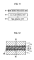
- Fig. 12 is a cross-sectional view showing a sealing structure according to an eighth embodiment which is according to the present invention.
- a seal member 79 makes a first component 73 and a second component 74 closely adhere to each other as in the first embodiment.
- the first component 73 and the second component 74 respectively include the base members 4 and 5 and hard carbon films 77 and 78 as well as intermediate layers 75 and 76 interposed therebetween.
- the intermediate layers 75 and 76 each have a columnar crystal structure, and gaps 80 constituting the groove portions are formed between the crystals.
- gaps 80 are formed in both sealing surfaces of the first component 73 and the second component 74 as shown in Fig. 12 , the gaps 80 may be formed only in one of the sealing surfaces.
- the configuration of the second component 74 will be described based on Figs. 13 to 16 .
- the configuration of the first component 73 is the same as that of the second component 74, and the description thereof will be omitted herein.
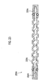
- Fig. 13 is an enlarged view of an XIII portion in Fig. 12 .
- the second component 74 includes: the base member 5; the hard carbon film 78 formed on the outermost surface of the second component 74; the intermediate layer 76 interposed therebetween and having a columnar crystal structure; and the gaps 80 between the crystals.
- the intermediate layer 76 has a function of improving the adhesiveness between the base member 5 and the hard carbon film 78 and a function of preventing ion elusion from the base member 5. These functions are further noticeably demonstrated when the base member 5 is made of aluminum or an alloy thereof.
- the material for the intermediate layer 76 is preferably one that provides the above adhesiveness.
- Examples thereof include Group 4 metals (Ti, Zr, Hf), Group 5 metals (V, Nb, Ta) and Group 6 metals (Cr, Mo, W) in the periodic table, carbides, nitrides, and carbonitrides thereof, and the like.
- a metal having less ion elution such as chromium(Cr), tungsten (W), titanium (Ti), molybdenum (Mo), niobium (Nb) or hafnium (Hf), or a nitride, carbide, or carbonitride thereof.
- More preferably used is Cr, Ti, or a carbide or nitride thereof.
- the roles of the intermediate layer 76 are to ensure the adhesiveness to the hard carbon film 78 on the upper side and the anticorrosive effect on the underlying base member 5.
- the base member 5 is formed of aluminum or an alloy thereof, the water content having reached near the interface causes corrosion to proceed, and an aluminum oxide film is formed.
- Chromium and titanium (or carbides or nitrides thereof) are particularly useful in that elution of such metals themselves is hardly observed even if a portion thereof is exposed due to formation of a passivation film.
- the corrosion resistance of the base member 5 can be significantly improved.
- the thickness of the intermediate layer 76 is not particularly limited. However, from the viewpoint of making the size of the final product as small as possible by forming the second component 74 more thinly, the thickness of the intermediate layer 76 is preferably 0.01 ⁇ m to 10 ⁇ m, more preferably 0.02 ⁇ m to 5 ⁇ m, further preferably 0.05 ⁇ m to 5 ⁇ m, and particularly preferably 0.1 ⁇ m to 1 ⁇ m. If the thickness of the intermediate layer 76 is 0.01 ⁇ m or larger, a uniform layer is formed. This makes it possible to effectively improve the corrosion resistance of the base member 5.
- the thickness of the intermediate layer 76 is 10 ⁇ m or smaller, an increase in the film stress on the film intermediate layer 76 is suppressed, and a decrease in the film followability to the base member 5 and the generation of peeling and cracks associated with the decrease are prevented.
- the columnar crystal structure of the intermediate layer 76 refers to a structure in which crystals of the metal for forming the intermediate layer 76 grow columnarly in a film thickness direction.
- the average thickness of columnar crystals in the cross section of the intermediate layer 76 is preferably 35 nm (upper limit: 80 nm, lower limit: 20 nm).
- the gaps 80 are gaps formed between the columnar crystals of the intermediate layer 76.
- the width of each gap is not particularly limited, but preferably 0.1 nm to 20 nm in a plan view, and the length is preferably in a range of 0.01 ⁇ m to 10 ⁇ m. Moreover, it is preferable that a large number of the gaps 80 be uniformly distributed in the surface of the intermediate layer 76.
- the depth of the gap 80 is not particularly limited, but from the viewpoint of enhancing the anchoring effect, the gap 80 is preferably formed as deep as possible within the thickness range of the intermediate layer 76.
- Fig. 13 is a view schematically representing the shape of the columnar crystals.
- the gap 80 includes a gap having a width widened from the base member side toward the outermost surface side, a gap having a width widened from the outermost surface side toward the base member side, and further a gap having a width irregularly changing from the end portion on the outermost surface side to the end portion on the base member side.
- the adjacent columnar crystals sandwiching the gap 80 therebetween are illustrated as if the columnar crystals are not in contact with each other.
- the adjacent columnar crystals sandwiching the gap 80 therebetween include those that are in contact with each other in an integrated manner at one spot or multiple spots on their side surfaces from the end portion on the outermost surface side to the end portion on the base member side.
- the gaps 80 are distributed as if a three-dimensional gap network is formed within the intermediate layer 76.
- the hard carbon film 78 formed on the outermost surface of the second component 74 is formed of particles 78a each having a diameter of 50 nm to 100 nm. Meanwhile, the hard carbon film 78 is not formed on the gaps 80 having sufficiently large widths in the outermost surface of the intermediate layer 76. The portion where the hard carbon film 78 is not formed and the gap 80 constitute the groove portion.
- a film forming method for the intermediate layer 76 having the columnar crystal structures and the hard carbon film 78 will be described below.
- an aluminum plate, its alloy plate, a titanium plate, a stainless steel plate, or the like having a desired thickness is prepared.
- degreasing and cleaning processes are performed on the surface of the prepared constituent material of the base member 5.
- the solvent it is possible to use ethanol, ethers, acetone, isopropyl alcohol, trichloroethylene, caustic alkali agent, and the like.
- the degreasing and cleaning processes include ultrasonic cleaning and the like.
- the processing time is approximately 1 to 10 minutes
- the frequency is approximately 30 to 50 kHz
- the power is approximately 30 to 50 W.
- an oxide film formed on the surface of the constituent material of the base member 5 is removed.
- Examples of the approach to remove the oxide film include a cleaning process with acid, a dissolution process by electric potential application, an ion bombardment process, and the like.
- the following method is preferably used in which: alkaline immersion cleaning, oxide film removal with alkali (alkali etching), and surface activation with a mixed acid solution containing hydrofluoric acid are performed; then, zincate treatment is performed in a zinc displacement bath.
- the conditions for the zincate treatment are not particularly limited.
- the bath temperature is 10 to 40°C
- the immersion time is 20 to 90 seconds.
- the above oxide film removal step may be omitted.
- the intermediate layer 76 and the hard carbon film 78 are sequentially formed.
- the constituent material for example, chromium
- the chromium intermediate layer 76 is stacked on the surface of the base member 5 (for example, aluminum or an alloy thereof) with a bias voltage to be described later.
- the constituent material for example, graphite
- a layer containing carbon is stacked at an atomic level on the surface of the intermediate layer 76.
- the adhesiveness of the interfaces between the hard carbon film 78, the intermediate layer 76 and the base member 5, which directly adhere to each other, and the adhesiveness therearound are retained over a long period of time by the intermolecular force and intrusion of a slight amount of carbon atoms.
- Examples of the approach suitably adopted in stacking the intermediate layer 76 and the hard carbon film 78 include physical vapor deposition (PVD) processes such as a sputtering process and an ion plating process; ion beam deposition processes such as a filtered cathodic vacuum arc (FCVA) process; and the like.
- PVD physical vapor deposition
- FCVA filtered cathodic vacuum arc
- Examples of the sputtering process include a magnetron sputtering process, an unbalanced magnetron sputtering (UBMS) process, a dual magnetron sputtering process, an ECR sputtering process, and the like.
- examples of the ion plating process include an arc ion plating process, and the like.
- the sputtering process and the ion plating process are preferably used, and the sputtering process is particularly preferably used.
- a carbon layer with less hydrogen content can be formed.
- the proportion of bonds between carbon atoms (sp 2 hybridized carbons) can be increased.
- the hard carbon film is requested to have a conductive property, an excellent conductive property can be achieved, and thus such a process is useful.
- the intermediate layer 76 having the above columnar crystal structure can be obtained by controlling the bias voltage or the like.
- the intermediate layer 76 and the hard carbon film 78 are formed by the sputtering process, a negative bias voltage should be applied to the base member 5 during the sputtering.
- the intermediate layer 76 having the columnar crystal structure and the hard carbon film 78 formed of densely assembled graphite clusters are formed by an ion irradiation effect.
- Such an intermediate layer 76 can enhance the anticorrosive effect on the base member 5, and enables even a corrosion susceptible metal such as aluminum to be employed as the base member 5.
- the component 74 is employed as a conductive member, there is an advantage that the contact resistance to another conductive member is made lower because the hard carbon film 78 demonstrates an excellent conductive property.
- the absolute value of the negative bias voltage to be applied is not particularly limited, and a voltage that enables the formation of the hard carbon film 78 is chosen.
- the magnitude of the voltage to be applied is preferably 50 to 500 V, more preferably 100 to 300 V.
- the intermediate layer 76 is formed with such a low bias voltage (should be over 0 V, or over 0 V to 50 V) as not to deteriorate the coarseness of the interface with the base member 5.
- the optimum columnar crystal structure can be controlled through a preparatory experiment or the like.
- the other conditions during the film formation are not particularly limited, and conventionally known findings can be referred as appropriate.
- the hard carbon film 78 is preferably formed on the intermediate layer 76 formed in advance using the same apparatus and formation method.
- the intermediate layer 76 and the hard carbon film 78 excellent in adhesiveness to the base member 5 are formed.
- the hard carbon film 78 may be formed using another apparatus and formation method on the intermediate layer 76 formed using different approach and apparatus. Even in this case, the intermediate layer 76 and the hard carbon film 78 excellent in adhesiveness to the base member 5 are formed.
- the intermediate layer 76 and the hard carbon film 78 are formed on one surface of the base member 5.
- the intermediate layer 76 and the hard carbon film 78 may be formed on the other surface of the base member 5 by the same approach.
- commercially available film forming apparatuses film forming apparatuses sputtering both surfaces simultaneously
- the intermediate layer 76 and the hard carbon film 78 are formed on one surface of the base member 5 followed by sequential formation of the intermediate layer 76 and the hard carbon film 78 on the other surface of the base member 5.
- the intermediate layer 76 is formed on one surface of the base member 5; subsequently, the intermediate layer 76 is formed on the other surface; the target is thereafter switched to carbon, and the hard carbon film 78 is formed on the intermediate layer 76 having been formed on the one surface; subsequently, the hard carbon film 78 is formed on the other surface.
- the same approach as those for the film formation on one surface can be adopted.
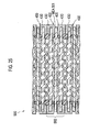
- Figs. 14 to 16 are a TEM photograph and SEM photographs for observing the surface of the base member 5 after the film formation.
- an aluminum plate (aluminum A1050) was prepared as the material of the base member 5.
- the thickness of the aluminum plate was 200 ⁇ m. This aluminum plate was used and subjected to ultrasonic cleaning in an ethanol solution for 3 minutes as a pretreatment. Then, the base member 5 was further placed in a vacuum chamber and subjected to an ion bombardment process with Ar gas to remove an oxide film on the surface.
- the hard carbon films 78 each having a thickness of 0.2 ⁇ m were formed on the Cr layers (the intermediate layers 76) on the respective surfaces of the aluminum plate, while a negative bias voltage with the magnitude of 140 V is being applied to the aluminum plate.
- the following state can be observed that the micro-particles 78a each having a diameter of 50 to 100 nm are present on the outermost surface, and the gaps 80 each having a width of approximately 20 nm and a length of approximately 1 ⁇ m are formed therebetween.
- the average thickness of the columnar crystals in the cross section of the intermediate layer 76 (i.e., the average value of the columnar thicknesses of the columnar crystals in the cross section of the intermediate layer 76) is 35 nm (upper limit: 80 nm, lower limit: 20 nm), and that the width of the gap formed therebetween is 50 nm. Furthermore, it can also be observed that the thickness of the Cr intermediate layer 76 is in a range of 0.02 ⁇ m to 5 ⁇ m.
- the hard carbon films 77 and 78 are formed on the outermost surfaces of the components 73 and 74. This improves the wettability of the seal member on the sealing surface. Further, in the sealing structure according to the eighth embodiment, the gaps 80 are formed between the columnar crystals in the intermediate layers 75 and 76. This increases the contact areas between the seal member 79 and the components 73 and 74 (specifically, the hard carbon film 77, 78 and the intermediate layer 75, 76), and an anchoring effect is also produced. Since the width of the gap 80 irregularly changes in the film thickness direction as described above, the anchoring effect is further enhanced. Thus, the adhesiveness of the seal member on the sealing surface is further improved, and a more stable sealing performance can be obtained.
- a bonding strength test was conducted on the sealing structure according to this embodiment in accordance with the method specified in Japanese Industrial Standards (JIS-K-6850).
- the adherends used were: ones each obtained by forming the Cr intermediate layer and the hard carbon film according to this embodiment on the surface of a plate made of a stainless steel (Examples 1, 2); and one obtained by performing gold plating on the surface of the same plate made of a stainless steel directly, that is, with no intermediate layer provided thereon (Comparative Example).
- the adhesive used were an olefin-based adhesive and a silicone-based adhesive. The maximum load at the time when each test piece is ruptured is proportional to the bonding strength of each test piece.
- the "columnar crystal thickness” refers to an average value of the thicknesses of columns of columnar crystals in the cross section of the intermediate layer. From Table 2, it can be seen that the bonding strengths in Examples 1 and 2 were 1.3 to 1.5 times higher than that in Comparative Example, and that the sealing structure according to this embodiment demonstrates more excellent adhesiveness.
- Fig. 17 is a cross-sectional view showing a sealing structure of a fuel cell according to a ninth embodiment of the present invention.
- the sealing structure according to the ninth embodiment is employed for a polymer electrolyte fuel cell (PEFC).
- PEFC polymer electrolyte fuel cell
- a fuel cell 90 is a stack type fuel cell that is a stack formed by stacking multiple single cells 94 one above the other.
- the single cell 94 is a single unit of the fuel cell in which a pair of sheet-shaped separators 95 (reference numeral 95 is not described in the drawing) and a sheet-shaped membrane electrode assembly 96 are stacked.
- the number of the cells in the stack is not particularly limited, and the fuel cell stack may be formed of only a single unit of the single cell 94, or multiples of the single cells 94 stacked.
- Separators 95a and 95c are each obtained by, for example, molding by pressing a thin plate having a thickness of 0.5 mm or smaller into a recessed and protruding shape as shown in Fig. 17 .
- the protruding portions, seen from the MEA side, of the separators 95a and 95c are in contact with the membrane electrode assembly 96. This ensures electrical connection to the membrane electrode assembly 96.
- the recessed portions, seen from the MEA side, of the separators 95a and 95c i.e., spaces which are formed between the MEA and the separators in accordance with the recessed and protruding shape of the separators
- fuel gas for example, hydrogen or the like
- oxidant gas for example, air or the like
- the fuel cell 90 first has a polymer electrolyte membrane 97, and a pair of catalytic layers (an anode catalytic layer 98a and a cathode catalytic layer 98c) sandwiching the polymer electrolyte membrane 97. Moreover, the stack of the polymer electrolyte membrane 97 and the catalytic layers 98a and 98c is further sandwiched by a pair of gas diffusion layers (GDLs) (an anode gas diffusion layer 99a and a cathode gas diffusion layer 99c).
- GDLs gas diffusion layers
- An electrolyte membrane supporter 100 is bonded to an edge portion of the stack of the polymer electrolyte membrane 97, the pair of catalytic layers 98a and 98c and the pair of gas diffusion layers 99a and 99c in the above state.
- the membrane electrode assembly (MEA) 96 is formed.
- the electrolyte membrane supporter 100 is formed of, for example, a thermosetting resin.
- the membrane electrode assembly 96 is sandwiched by the pair of separators (the anode separator 95a and the cathode separator 95c).
- the membrane electrode assembly 96 is sequentially stacked on another membrane electrode assembly 96 with the separator 95 interposed therebetween, and thus the stack is formed.
- the recessed portions, seen from a side opposite to the MEA side, of the separators 95a and 95c are formed to serve as coolant flow paths 101 for allowing a coolant (for example, water) to flow for cooling the fuel cell 90 during the operation of the fuel cell.
- a manifold (unillustrated) is generally provided in the separator 95. The manifold functions as connection means for connecting each cell to the other when the stack is formed. Such a configuration can ensure the mechanical strength of the fuel cell stack.
- the conductive member constituting the separators 95a and 95c has a metal base member layer 102 (base member) and conductive carbon layers 103 (hard carbon films) formed on both surfaces of the metal base member layer 102.
- a metal base member layer 102 base member
- conductive carbon layers 103 hard carbon films
- an intermediate layer made of another material may be interposed between the metal base member layer 102 and the conductive carbon layer 103, as described above.
- a first seal member 104 makes the separator 95 and the electrolyte membrane supporter 100 (part of the membrane electrode assembly 96) closely adhere to each other. Edge portions of the separators 95a and 95c lying on each other are made to closely adhere to each other by a second seal member 105. Further, edge portions of the electrolyte membrane supporters 100 lying on each other are made to closely adhere to each other by a third seal member 106.
- the metal base member layer 102 is a main layer of the conductive member constituting the separator 95, and contributes to ensuring the conductive property and the mechanical strength.
- the metal for forming the metal base member layer 102 is not particularly limited, and those conventionally used as the constituent material of a metal separator can be used as appropriate.
- the constituent material of the metal base member layer include iron, titanium, aluminum, and alloys thereof. These materials can be preferably used from the viewpoints of mechanical strength, versatility, cost performance, processing easiness, or the like.
- the iron alloys include stainless steels.
- the metal base member layer is preferably formed of a stainless steel, aluminum or an aluminum alloy. Furthermore, particularly when a stainless steel is used for the metal base member layer, the conductive property of the contact surface with a gas diffusion base member that is the constituent material of the gas diffusion layer can be sufficiently ensured. As a result, even if water content intrudes into a film gap at a shoulder rib portion or the like, the durability can be retained by the corrosion resistance of the oxide film formed on the metal base member layer itself that is formed of the stainless steel.
- the thickness of the metal base member layer 102 is not particularly limited. From the viewpoints of processing easiness, mechanical strength, improvement in energy density of the cell attributed to thinly formed separator itself, and the like, the thickness is preferably 50 to 500 ⁇ m, more preferably 80 to 300 ⁇ m, and further preferably 80 to 200 ⁇ m. Particularly, when a stainless steel is used for the constituent material, the thickness of the metal base member layer 102 is preferably 80 to 150 ⁇ m. Meanwhile, when aluminum is used for the constituent material, the thickness of the metal base member layer 102 is preferably 100 to 300 ⁇ m. When the thickness is within the above-described range, the metal base member layer 102 is excellent in processing easiness and can have a favorable thickness, while having a sufficient strength as the separator.
- the conductive carbon layer 103 is a layer containing conductive carbon. The presence of this layer ensures the conductive property of the conductive member constituting the separator 95. Moreover, the corrosion resistance is improved and the adhesiveness to the seal member can be improved in comparison with a case of the metal base member layer 102 alone. Note that, in this embodiment, the conductive carbon layer is employed as the hard carbon film that closely adheres to the seal member; however, if the hard carbon film is provided only at a portion contacting the seal member, the hard carbon film does not need to have a conductive property. Thus, the conductive property does not always have to be provided thereto.
- the conductive carbon layer 103 is preferably specified by a strength ratio R (I D /I G ) of a D-band peak strength (I D ) to a G-band peak strength (I G ) measured by Raman scattering spectroscopic analysis.
- the strength ratio R (I D /I G ) is preferably 1.3 or higher.
- peaks When a carbon material is analyzed by Raman spectroscopy, peaks generally appear around 1350 cm -1 and around 1584 cm -1 .
- a graphite having a high crystallinity has a single peak around 1584 cm -1 . This peak is generally referred to as a "G band.”
- a peak around 1350 cm -1 appears. This peak is generally referred to as a "D band” (note that the peak of a diamond is strictly at 1333 cm -1 , and distinguished from the D band).
- the strength ratio R (I D /I G ) of the D-band peak strength (I D ) to the G-band peak strength (I G ) is used as an index for the size of graphite cluster of a carbon material, how much the graphite structure is disturbed (defects in the crystal structure), the proportion of sp 2 bonds, or the like.
- the strength ratio R (I D /I G ) can serve as the index for the contact resistance of the conductive carbon layer 103, and can be used as a film parameter for controlling the conductive property of the conductive carbon layer 103.
- the R (I D /I G ) value is calculated by measuring the Raman spectrum of the carbon material using a Raman microspectroscope. Specifically, the R (I D /I G ) value is obtained by calculating the relative strength ratio (peak area ratio (I D /I G )) of the peak strength (I D ) of 1300 to 1400 cm -1 called the D band to the peak strength (I G ) of 1500 to 1600 cm -1 called the G band.
- the R value is preferably 1.3 or higher. Moreover, the R value is more preferably 1.4 to 2.0, further preferably 1.4 to 1.9, and further still preferably 1.5 to 1.8.
- the conductive carbon layer having a conductive property in the stacking direction sufficiently ensure is obtained.
- the R value is 2.0 or lower, a decrease in the graphite component can be suppressed. Further, an increase in the internal stress of the conductive carbon layer itself can also be suppressed, and the adhesiveness to the underlying metal base member layer (or an intermediate layer if the intermediate layer is present) can be further improved.
- the conductive carbon layer 103 may be formed substantially only of a polycrystalline graphite or only of a polycrystalline graphite.
- the conductive carbon layer 103 may also contain a material other than the polycrystalline graphite.
- Examples of the carbon material other than the polycrystalline graphite, which may be contained in the conductive carbon layer 103 include graphite blocks (high crystallinity graphite), carbon blacks, fullerenes, carbon nanotubes, carbon nanofibers, carbon nanohoms, carbon fibrils, and the like.
- specific examples of the carbon black include, but are not limited to, the followings: ketjen black, acetylene black, channel black, lamp black, oil furnace black, thermal black, and the like.
- the carbon black may be subjected to graphitization.
- these carbon materials may be used in the form of complex with a resin such as a polyester based resin, an aramid based resin, and a polypropylene based resin.
- a resin such as a polyester based resin, an aramid based resin, and a polypropylene based resin.
- Other examples of the material other than the carbon material, which may be contained in the conductive carbon layer 103, include noble metals such as gold (Au), silver (Ag), platinum (Pt), ruthenium (Ru), palladium (Pd), rhodium (Rh), and indium (In); water repellent substances such as polytetrafluoroethylene (PTFE); conductive oxides; and the like.
- the material other than the polycrystalline graphite may be used alone or in combination of two or more kinds.
- the thickness of the conductive carbon layer 103 is not particularly limited. However, the thickness is preferably 1 to 1000 nm, more preferably 2 to 500 nm, and further preferably 5 to 200 nm. When the value of the thickness of the conductive carbon layer is within such a range, a sufficient conductive property can be ensured between the gas diffusion base member and the separator. Additionally, it is possible to achieve such an advantageous effect of a high anticorrosive function provided to the metal base member layer.
- the Vickers hardness of the conductive carbon layer 103 is specified.
- the "Vickers hardness (Hv)" is a value for specifying the hardness of a substance, and a unique value to a substance.
- the Vickers hardness means a value measured by a nanoindentation method.
- the nanoindentation method is an approach in which a diamond indenter with an extremely small load is continuously loaded or unloaded on a sample surface, and the hardness is measured from a load-displacement curve thus obtained.
- the higher Hv means that the substance is harder.
- the Vickers hardness of the conductive carbon layer 103 is preferably 1500 Hv or lower, more preferably 1200 Hv or lower, further preferably 1000 Hv or lower, and particularly preferably 800 Hv or lower.
- the value of the Vickers hardness is within such a range, excessive intrusion of sp 3 carbon not having a conductive property is suppressed, and a decrease in the conductive property of the conductive carbon layer 103 can be prevented.
- the lower limit value of the Vickers hardness is not particularly limited. However, if the Vickers hardness is 50 Hv or higher, the hardness of the conductive carbon layer 103 is sufficiently ensured.
- the conductive carbon layer 103 can more firmly closely adhere to the intermediate layer, and an excellent conductive member can be provided.
- the Vickers hardness of the conductive carbon layer 103 is more preferably 80 Hv or higher, further preferably 100 Hv or higher, and particularly preferably 200 Hv or higher. Note that, herein, the Vickers hardness of the hard carbon film preferably falls within the above range.
- a method for producing the above-described conductive member is not particularly limited, and the production is possible by referring to conventionally known approaches as appropriate.
- an example of producing the conductive member will be illustrated. Meanwhile, conditions such as the material of each constituent of the conductive member constituting the separator 95 are as described above, and the description thereof will be omitted here.
- a stainless steel plate or the like having a desired thickness is prepared as the constituent material of the metal base member layer. Then, using an appropriate solvent, degreasing and cleaning processes are performed on the surface of the prepared constituent material of the metal base member layer. Subsequently, an oxide film formed on a surface (or both surfaces) of the constituent material of the metal base member layer is removed. Thereafter, a conductive carbon layer is formed on the surface of the constituent material of the metal base member layer having being subjected to the above-described processes.
- the details of these steps and the approach suitably used for stacking the conductive carbon (film formation) have been described in detail in the eighth embodiment, and the descriptions thereof will be omitted here.
- a negative bias voltage should be applied to the metal base member layer during the sputtering.
- a conductive carbon layer having a structure in which graphite clusters are densely assembled can be formed by an ion irradiation effect.
- Such a conductive carbon layer can demonstrate an excellent conductive property.
- the magnitude (absolute value) of the negative bias voltage to be applied is not particularly limited, and a voltage that enables the formation of the conductive carbon layer can be chosen.
- the magnitude of the voltage to be applied is preferably 50 to 500 V, more preferably 100 to 300 V.
- specific modes such as other conditions in the film formation are not particularly limited, and conventionally known findings can be referred as appropriate.
- the conductive carbon layer 103 is formed by the UBMS process, the conductive carbon layer is preferably formed on an intermediate layer formed in advance. Thereby, a conductive carbon layer excellent in adhesiveness to the underlying layer can be formed. Nonetheless, even when the conductive carbon layer is formed by another approach, the conductive carbon layer excellent in adhesiveness to the metal base member layer can be formed even in the absence of an intermediate layer.
- An electrolyte layer is constituted from, for example, the polymer electrolyte membrane 97.
- the polymer electrolyte membrane 97 has a function of selectively permeating protons generated at the anode catalytic layer 98a during the operation of the fuel cell into the cathode catalytic layer 98c in the film thickness direction. Additionally, the polymer electrolyte membrane 97 also has a function as a partition not to mix fuel gas supplied to the anode side with oxidant gas supplied to the cathode side.
- the polymer electrolyte membrane 97 is roughly classified into a fluorinated polymer electrolyte membrane and a hydrocarbon based polymer electrolyte membrane according to the type of the ion-exchange resin that is a constituent material thereof.
- the ion-exchange resin constituting the fluorinated polymer electrolyte membrane include perfluorocarbon sulfonic acid based polymers such as Nafion (registered trademark, manufactured by E. I.
- du Pont de Nemours & Company Inc.
- Aciplex registered trademark, manufactured by Asahi Kasei Corporation
- Flemion registered trademark, manufactured by Asahi Glass Co., Ltd.
- perfluorocarbon phosphonic acid based polymers trifluorostyrene sulfonic acid based polymers, ethylene tetrafluoroethylene-g-styrene sulfonic acid based polymers, ethylene-tetrafluoroethylene copolymers, polyvinylidene fluoride-perfluorocarbon sulfonic acid based polymers, and the like.
- these fluorinated polymer electrolyte membranes are preferably used, and a fluorinated polymer electrolyte membrane formed of a perfluorocarbon sulfonic acid based polymer is particularly preferably used.
- hydrocarbon based electrolyte examples include sulfonated polyethersulfone (S-PES), sulfonated polyaryletherketone, alkyl sulfonated polybenzimidazole, alkyl phosphonated polybenzimidazole, sulfonated polybenzimidazole alkyl, phosphonated polybenzimidazole alkyl, sulfonated polystyrene, sulfonated polyetheretherketone (S-PEEK), sulfonated polyphenylene (S-PPP), and the like.
- S-PES sulfonated polyethersulfone
- S-PEEK sulfonated polyaryletherketone
- S-PEEK sulfonated polyphenylene
- these hydrocarbon based polymer electrolyte membranes are preferably used.
- the above-described ion-exchange resins may be used alone or in combination of two or more kinds.
- the material is not limited only to the above-described materials, and other materials may be used.
- the thickness of the electrolyte layer should be determined as appropriate in consideration of the properties of the fuel cell to be obtained, and is not particularly limited.
- the thickness of the electrolyte layer is generally approximately 5 to 300 ⁇ m. When the value of the thickness of the electrolyte layer is within such a range, the balance between the strength during the film formation, the durability during the use, and the output property during the use can be controlled properly.
- the catalytic layers are layers where actually cell reactions proceed. Specifically, a hydrogen oxidation reaction proceeds in the anode catalytic layer 98a, and an oxygen reduction reaction proceeds in the cathode catalytic layer 98c.
- Each catalytic layer includes a catalyst component, a conductive catalyst support for supporting the catalyst component, and an electrolyte.
- a complex of the catalyst component and the catalyst support supporting the catalyst component is also referred to as an "electrode catalyst.”
- the catalyst component used in the anode catalytic layer is not particularly limited, as long as it has a catalytic action for the hydrogen oxidation reaction.
- Known catalysts can be used similarly.
- the catalyst component used in the cathode catalytic layer is also not particularly limited, as long as it has a catalytic action for the oxygen reduction reaction.
- Known catalysts can be used similarly.
- the catalyst components can be selected from metals such as platinum, ruthenium, iridium, rhodium, palladium, osmium, tungsten, lead, iron, chromium, cobalt, nickel, manganese, vanadium, molybdenum, gallium and aluminum, alloys thereof, and the like.
- one containing at least platinum is preferably used to improve the catalytic activity, poisoning resistance to carbon monoxide or the like, heat resistance, and so forth.
- the composition of the alloy although depending on the type of metal to be alloyed, preferably contains 30 to 90 atom% of platinum and 10 to 70 atom% of a metal alloyed with platinum. Note that the alloy is generally composed of a metal element and one or more kinds of metal element or non-metal element added thereto, and is a collective term for those having metallic properties.
- the constitution of the alloy examples include a eutectic alloy that may be called a mixture of component elements respectively forming crystals, a solid solution in which component elements are completely blended together, an intermetallic compound formed of component elements, a compound of metallic and non-metallic component elements, and the like.
- a eutectic alloy that may be called a mixture of component elements respectively forming crystals
- a solid solution in which component elements are completely blended together an intermetallic compound formed of component elements, a compound of metallic and non-metallic component elements, and the like.
- the catalyst component used in the anode catalytic layer and the catalyst component used in the cathode catalytic layer can be selected as appropriate from the above. Unless otherwise specified herein, the same definition will be given in both the descriptions of the catalyst components for the anode catalytic layer and for the cathode catalytic layer.
- catalyst component both are collectively referred to as a "catalyst component.” Nevertheless, the catalyst components for the anode catalytic layer and for the cathode catalytic layer do not have to be the same.
- the catalyst components can be selected as appropriate so as to have desired actions as described above.
- the shape and size of the catalyst component are not particularly limited, and the same shape and size as those of known catalyst components can be adopted.
- the shape of the catalyst component is preferably particulate.
- the average particle diameter of the catalyst particles is preferably 1 to 30 nm. When the value of the average particle diameter of the catalyst particles is within such a range, the balance between the catalyst utilization efficiency associated with the effective electrode area where the electrochemical reaction proceeds and the supporting easiness can be controlled properly.
- the "average particle diameter of catalyst particles” can be measured as a crystallite diameter obtained from a half width of a diffraction peak of the catalyst component in an X-ray diffraction, or as an average value of particle diameters of the catalyst component examined from a transmission electron microscope image.
- the catalyst support functions as a support for supporting the above-described catalyst component and as an electron conduction path involved in electron transfer between the catalyst component and another member.
- the catalyst support should have a specific surface area for supporting the catalyst component in a desired dispersed state and have a sufficient electron conductivity.
- the main component thereof is preferably carbon. Specific examples thereof include carbon particles formed of carbon black, activated carbon, coke, natural graphite, artificial graphite, and the like.
- the phrase "main component is carbon” means that carbon atoms are contained as the main component, and is a concept including both that the main component is composed of only carbon atoms and that the main component is substantially composed of carbon atoms. Depending on cases, an element other than the carbon atoms may be contained to enhance the properties of the fuel cell. Note that the phrase "substantially composed of carbon atoms" means that the inclusion of an impurity by approximately 2 to 3% by mass or less is acceptable.
- the specific surface area of the catalyst support should be sufficient to support the catalyst component in a highly dispersed state, and is preferably 20 to 1600 m 2 /g, more preferably 80 to 1200 m 2 /g.
- the value of the specific surface area of the catalyst support is within such a range, the balance between the dispersibility of the catalyst component on the catalyst support and the effective utilization efficiency of the catalyst component can be controlled properly.
- the size of the catalyst support is not particularly limited. However, from the viewpoints of supporting easiness, catalyst utilization efficiency, controlling the thickness of the catalytic layer in a proper range, and the like, the average particle diameter should be approximately 5 to 200 nm, preferably approximately 10 to 100 nm.
- the amount of the catalyst component supported is preferably 10 to 80% by mass, more preferably 30 to 70% by mass, relative to the total amount of the electrode catalyst.
- the value of the amount of the catalyst component supported is within such a range, the balance between the catalytic performance of the catalyst component on the catalyst support and the dispersibility can be controlled properly.
- the amount of the catalyst component supported in the electrode catalyst can be measured by inductively coupled plasma spectrometry (ICP).
- the catalytic layer includes an ion conductive polymer electrolyte in addition to the electrode catalyst.
- the polymer electrolyte is not particularly limited, and conventionally known findings can be referred as appropriate.
- the above-described ion-exchange resin constituting the electrolyte layer may be added as the polymer electrolyte to the catalytic layer.
- the gas diffusion layers (the anode gas diffusion layer 99a, the cathode gas diffusion layer 99c) have a function of promoting diffusion of gas (fuel gas or oxidant gas) supplied through the gas flow path 96a or 96c of the separator to the catalytic layers 98a and 98c, and a function as an electron conduction path.
- the material for the base members of the gas diffusion layers 99a and 99c is not particularly limited, and conventionally known findings can be referred as appropriate. Examples thereof include sheet-shaped materials having conductive property and porosity, such as carbon-made fabric, final paper product, felt, and nonwoven fabric.
- the thickness of the base member should be determined as appropriate in consideration of the properties of the gas diffusion layer to be obtained. However, the thickness should be approximately 30 to 500 ⁇ m. When the value of the thickness of the base member is within such a range, the balance between the mechanical strength and the diffuseness of gas, water, and the like can be controlled properly.
- the gas diffusion layer preferably includes a water repellent in order to further increase the water repellency, thus preventing a flooding phenomenon or the like.
- the water repellent is not particularly limited. Examples thereof include fluorinated polymer materials such as polytetrafluoroethylene (PTFE), polyvinylidene fluoride (PVdF), polyhexafluoropropylene, and tetrafluoroethylene-hexafluoropropylene copolymers (FEP), polypropylene, polyethylene, and the like.
- PTFE polytetrafluoroethylene
- PVdF polyvinylidene fluoride
- FEP tetrafluoroethylene-hexafluoropropylene copolymers
- the gas diffusion layer may have a carbon particle layer (micro-porous layer; MPL, unillustrated) on the catalytic layer side of the base member.
- the carbon particle layer is an assembly of carbon particles containing a water repellent.
- the carbon particles included in the carbon particle layer are not particularly limited, and conventionally known materials such as carbon blacks, graphites and expanded graphites can be employed as appropriate. Above all, having an excellent electron conductivity and a large specific surface area, carbon blacks such as oil furnace black, channel black, lamp black, thermal black, acetylene black can be preferably used.
- the average particle diameter of the carbon particles should be approximately 10 to 100 nm. Thereby, a high drainage capacity is obtained due to a capillary force, and contacting with the catalytic layer can also be improved.
- the water repellent used in the carbon particle layer may be the same as the above-described water repellent. Above all, being excellent in water repellency, the corrosion resistance during the electrode reaction, and the like, a fluorinated polymer material can be preferably used.
- the mixing ratio between the carbon particles and the water repellent in the carbon particle layer should be approximately 90:10 to 40:60 (carbon particle:water repellent) in terms of mass ratio in consideration of the balance between the water repellency and the electron conductivity.
- the thickness of the carbon particle layer is also not particularly limited, and should be determined as appropriate in consideration of the water repellency of the gas diffusion layer to be obtained.
- the seal member is not particularly limited.
- a thermosetting resin can be employed.
- the thermosetting resin it is possible to use, for example, an olefin resin, a urethane resin, a silicone resin, a phenol resin, an epoxy resin, an unsaturated polyester, or the like.
- the method for producing the fuel cell is not particularly limited, and conventionally known findings in the field of fuel cells can be referred as appropriate.
- the fuel used during the operation of the fuel cell is not particularly limited.
- hydrogen, methanol, ethanol, 1-propanol, 2-propanol, 1-butanol, secondary butanol, tertiary butanol, dimethyl ether, diethyl ether, ethylene glycol, diethylene glycol, or the like can be used.
- hydrogen or methanol is preferably used.
- a fuel cell stack may be formed, the fuel cell stack having a structure in which the multiple membrane electrode assemblies are stacked and connected in series with the separators interposed therebetween.
- the shape and the like of the fuel cell are not particularly limited, and should be determined as appropriate so as to obtain desired cell properties such as voltage.
- the conductive carbon layer 103 (hard carbon film) is formed in the separator 95.
- the first seal member 104 makes the hard carbon film and the resin member (electrolyte membrane supporter) closely adhere to each other
- the second seal member 105 makes the hard carbon films closely adhere to each other
- the third seal member 106 makes the resin members closely adhere to each other.
- closely adhering portions differ from each other in adhesiveness (sealing performance) due to the difference in the surface properties of the materials.
- the conductive carbon layer 103 (hard carbon film) having higher adhesiveness to the seal member than a resin member in a general sense is formed at least in the separator 95.
- the use of the conductive carbon layer 103 as the hard carbon film of the separator 95 can ensure the corrosion resistance and the conductive property of the separator 95. Thus, it is no longer necessary to form a hard carbon film only for improving the adhesiveness to the seal members 104 and 105.
- the separator 95 is molded in the recessed and protruding shape by performing press working on a plate-shaped conductive member (base member).
- a separator base member having a hard carbon film formed in advance to thus form cracks in a sealing surface as in the seventh embodiment (see Fig. 10 )
- the adhesiveness to the seal members 104 and 105 can be further improved by an increased surface area and an anchoring effect.
- Fig. 18 is a cross-sectional view showing a sealing structure of a polymer electrolyte fuel cell (PEFC) according to a tenth embodiment of the present invention.
- PEFC polymer electrolyte fuel cell
- a fuel cell 109 according to the tenth embodiment has substantially the same configuration as that of the fuel cell 90 according to the ninth embodiment, but differs only in a configuration that a hard carbon film 108 is formed on an electrolyte membrane supporter 107. Note that since electrolyte membrane supporter 107 is not required to have a conductive property, the hard carbon film 108 formed is desirably nonconductive.
- all the first to the third seal members 104, 105, 106 make hard carbon films closely adhere to each other.
- the same sealing material can be employed for the first to the third seal members 104, 105, 106 to provide high adhesiveness to all the seal members.
- Fig. 19 is a perspective view of a fuel cell separator according to an eleventh embodiment.
- Fig. 20 is a cross-sectional view taken along the line XX-XX in Fig. 19 .
- Fig. 21 is a graph illustrating contact resistance.
- a fuel cell separator 110 has a flat base member 111.
- the base member 111 has: a surface 113 (first surface) extending in a plane direction of the base member 111; and a peripheral edge surface 114 extending in a thickness direction of the base member 111 from a peripheral edge of the surface 113.
- manifold openings 115 each for allowing fuel gas, oxidant gas or cooling water to flow therethrough; and flow path grooves 112 for forming flow paths communicating with the manifold openings 115.
- the fuel gas is for example hydrogen or methanol.
- the oxidant gas is for example air.
- the surfaces of the flow path grooves 112 are covered with a conductive hard carbon film 120 having a conductive property.
- an active area 116 of the surface 113 is covered with the conductive hard carbon film 120.
- the active area 116 is a region on the surface 113 including the flow path grooves 112.
- the separator 110 further has an insulating hard carbon film 130 having an insulative property.
- the insulating hard carbon film 130 covers the peripheral edge surface 114 of the base member 111 and a region around the region of the surface 113 covered with the conductive hard carbon film 120.
- a seal member 140 is disposed on the surface 113 in such a manner as to surround the region covered with the conductive hard carbon film 120.
- the insulating hard carbon film 130 covers the peripheral edge surface 114 and a region from the peripheral edge of the surface 113 to the seal member 140.
- a peripheral edge portion, in a plane direction, of the conductive hard carbon film 120 is in contact with the seal member 140.
- seal member 140 is disposed on the surface 113 in such a manner as to surround peripheries of the flow path grooves 112 and the manifold openings 115 communicating with the flow path grooves 112 and a periphery of the other manifold openings 115.
- the base member 111 is made of a metal, and contributes to ensuring the conductive property and the mechanical strength.
- the metal for forming the base member 111 is not particularly limited, and known metals can be used as appropriate. Examples of the constituent material of the base member 111 include iron, titanium, aluminum, and alloys thereof.
- the conductive hard carbon film 120 is a film containing conductive carbon.
- the conductive hard carbon film 120 is specified by a strength ratio R (ID/IG) of a D-band peak strength (ID) to a G-band peak strength (IG) measured by Raman scattering spectroscopic analysis.
- the strength ratio R (ID/IG) is 1.3 or higher.
- the R is preferably 1.4 to 2.0, more preferably 1.4 to 1.9, and further preferably 1.5 to 1.8.
- the R value is 1.3 or higher, the conductive hard carbon film 120 having a conductive property in the stacking direction sufficiently ensured is obtained.
- the R value is 2.0 or lower, a decrease in the graphite component can be suppressed. Further, an increase in the internal stress of the conductive hard carbon film 120 itself can also be suppressed, and the adhesiveness to the underlying base member 111 can be further improved.
- the conductive hard carbon film 120 has a polycrystalline graphite structure.
- the "polycrystalline graphite” microscopically has an anisotropic graphite crystal structure (graphite cluster) in which graphene planes (hexagonal net planes) are stacked one above the other, and is macroscopically isotropic crystal body that is an assembly of the multiple graphite structures.
- the polycrystalline graphite is a type of diamond-like carbon (DLC; Diamond-Like Carbon).
- the conductive hard carbon film 120 may be formed only of a polycrystalline graphite, but the conductive hard carbon film 120 may also contain a material other than the polycrystalline graphite.
- Examples of the carbon material other than the polycrystalline graphite, which may be contained in the conductive hard carbon film 120, include carbon blacks, fullerenes, carbon nanotubes, carbon nanofibers, carbon nanohorns, carbon fibrils, and the like.
- the insulating hard carbon film 130 is a carbon film containing an insulating carbon and excellent in insulative property.
- the insulating hard carbon film 130 is for example a carbon film having a diamond-like crystal structure or a carbon film containing hydrogen.
- the thickness of the insulating carbon layer 130 is not particularly limited. However, the thickness is preferably 1 to 1000 nm, more preferably 2 to 500 nm, and further preferably 5 to 200 nm. When the value of the thickness of the insulating carbon layer is within this range, sufficient insulation can be ensured. Additionally, it is possible to achieve such an advantageous effect of a higher corrosion resistance provided to the metal base member layer.
- Fig. 21 is a graph illustrating the contact resistance of the hard carbon film under a condition where the contact surface pressure was at 1 MPa. As shown in Fig. 21 , while the contact resistance of the oxide film formed as a result of the acid cleaning process was 100 to 1000 m ⁇ cm 2 , the contact resistance of the insulating hard carbon film 130 was 5000 to 11000 m ⁇ cm 2 . Thus, the insulating hard carbon film 130 has an excellent insulative property in comparison with the oxide film. Note that the contact resistance of the conductive hard carbon film 120 was 20 m ⁇ cm 2 or lower.
- the fuel cell separator has functions of electrically connecting the single cells to each other and also allowing fuel gas or oxidant gas to flow into the fuel cell stack. For this reason, the fuel cell separator is preferably excellent in both conductive property and corrosion resistance.
- the separator 110 of the eleventh embodiment the insulating hard carbon film 130 demonstrating an excellent insulative property in comparison with, for example, an oxide film covers the peripheral edge surface 114 of the base member 111.
- the separator 110 is capable of inhibiting the electrical connection to another article, device, or the like because of the insulating hard carbon film 130, and has an excellent insulative property.
- the insulation at the peripheral portion is favorable, it is no longer necessary to additionally provide, for example, an insulating cover or the like, and a reduction in device size or cost can be achieved.
- the separator 110 Since having the conductive hard carbon film 120, the separator 110 has a high corrosion resistance in comparison with a case of the base member 111 alone, while ensuring the conductive property.
- the insulating hard carbon film 130 covers not only the peripheral edge surface 114 of the base member 111 but also the region around the region of the surface 113 covered with the conductive hard carbon film 120.
- the insulating hard carbon film 130 covers not only the peripheral edge surface 114 but also the region from the peripheral edge of the surface 113 to the seal member 140.
- Fig. 22 is a cross-sectional view of a fuel cell separator of a twelfth embodiment.
- a fuel cell separator 200 of the twelfth embodiment is substantially the same as that of the eleventh embodiment. However, a region of a base member 210 covered with an insulating hard carbon film 230 in this embodiment is different from that in the eleventh embodiment.
- the insulating hard carbon film 230 covers a peripheral edge surface 213, a region from a peripheral edge of a surface 212 (first surface) to a seal member 240, and a region from the seal member 240 on the surface 212 to a peripheral edge portion of a conductive hard carbon film 220.
- a boundary between the conductive hard carbon film 220 and the insulating hard carbon film 230 is located inwardly of the seal member 240.
- Fig. 23 is a cross-sectional view of a fuel cell separator according to a modified example of the twelfth embodiment.
- the position of a boundary between a region covered with an insulating hard carbon film 230A and a region covered with a conductive hard carbon film 220A may be shifted in a plane direction on one surface of a separator 200A from the other surface thereof.
- Fig. 24 is cross-sectional view of a fuel cell separator of a thirteenth embodiment.
- a separator 300 of the thirteenth embodiment is substantially the same as that of the eleventh embodiment. However, this embodiment is different from the eleventh embodiment in a region of a base member 310 covered with an insulating hard carbon film 330 and a region of the base member 310 covered with a conductive hard carbon film 320.
- the insulating hard carbon film 330 covers only a peripheral edge surface 313, while the conductive hard carbon film 320 covers a surface 312 (first surface) entirely.
- the thirteenth embodiment With such a configuration of the thirteenth embodiment, substantially the same effects as those in the eleventh embodiment are achieved. Further, in the thirteenth embodiment, since the insulating hard carbon film 330 does not cover the surface 312, the time of forming the insulating hard carbon film 330 can be shortened in comparison with the eleventh embodiment.
- the insulating hard carbon film and the conductive hard carbon film are formed so as not to overlap each other. Nevertheless, the insulating hard carbon film may be formed to overlap the conductive hard carbon film. For example, after the conductive hard carbon film is formed on the entire surface 113 of the base member 111, the insulating hard carbon film 130 may be formed so as to overlap a region of the conductive hard carbon film where insulation is needed.
- Fig. 25 is a schematic cross-sectional view of a fuel cell stack.
- a fuel cell stack 500 has a structure in which multiple single cells 502 having a power generating function are stacked one above the other.
- Each of the single cells 502 has a membrane electrode assembly 501 for an electrochemical reaction to proceed and a pair of separators 400 sandwiching the membrane electrode assembly 501 therebetween.
- the separators 400 each have the same configuration as that in the eleventh embodiment.
- the separator 400 may have the same configuration as that in the twelfth embodiment.
- the fuel cell stack 500 has a configuration in which the separators 400 lie on each other at portions where the single cells 502 are in contact with each other. Between these separators 400 lying on each other, insulating hard carbon films 430 are in contact with each other.
- the fuel cell stack 500 has the separators 400 each having the same configuration as that of the separator of the eleventh embodiment or the twelfth embodiment, the same effects as in these embodiments are achieved. Further, since the insulating hard carbon films 430 are in contact with each other between the separators 400 lying on each other, intrusion of water is suppressed, and insulation can be ensured inside and outside the fuel cell stack 500.
- Fig. 26 is a flowchart illustrating a method for producing a fuel cell separator.
- Fig. 27 is a cross-sectional view for explaining how base members are stacked.
- Fig. 28 is a cross-sectional view with an insulating hard carbon film being formed.
- some of the above-described members are shown in simplified forms.
- the base members 111 are molded (S 11). Then, the base members 111 are placed in a film forming apparatus for conductive hard carbon film, and the conductive hard carbon films 120 are formed (S12). Next, the base members 111 are taken out (S 13), and the base members 111 each having a buffer member disposed on the surface 113 are stacked one above the other with the buffer member interposed therebetween (stacking step: S14). The stacked base members 111 (stack) are placed in a film forming apparatus for insulating hard carbon film, and the insulating hard carbon film is formed (insulating hard carbon film-forming step: S15). Thereafter, the stack is taken out (S16).
- a plate member made of a metal such as a stainless steel or titanium is pressed and thus molded to the base member 111 having a predetermined shape.
- the base member 111 is subjected to ultrasonic cleaning in ethanol as a pretreatment. Then, the base member 111 is placed in a vacuum chamber and subjected to an ion bombardment process with Ar gas to remove an oxide film and impurities on the surface.
- an unbalanced magnetron sputtering (UBMS) process using Cr as a target Cr films are formed on both surfaces of the base member 111. Further, by the UBMS process using a solid graphite as a target, the conductive hard carbon films 120 are formed at required spots on both the surfaces of the base member 111, while a negative bias voltage at 110 V is being applied to the base member 111.
- UBMS unbalanced magnetron sputtering
- the base members 111 when the base members 111 are stacked, the base members 111 are stacked with the buffer member interposed between the stacked members.
- the buffer member is disposed on the surface 113 in such a manner as to surround the flow path grooves 112; in addition, covers 520 for covering the flow path grooves 112 are disposed on the outer surfaces 113 of the base members 111 positioned at both ends in the stacking direction between the multiple base members 111 thus stacked.
- the cover 20 may be either a resin film or a metallic plate, as long as the cover can mask the flow path grooves 112.
- the seal member 140 is used as the buffer member.
- Forming the insulating hard carbon film 130 is the same as the forming the conductive hard carbon film 120 from the pretreatment to the formation of Cr films.
- a plasma is created by high-frequency discharge in a vacuum chamber, and carbon and hydrogen are deposited on the base member 111 by the plasma CVD process.
- the insulating hard carbon film 130 is formed on the peripheral edge surface 114 and on the region from the peripheral edge of the surface 113 to the seal member 140.
- the insulating hard carbon film 130 may be formed to overlap the conductive hard carbon film 120. Specifically, the insulating hard carbon film may be formed in S 15 so as to overlap a region of the conductive hard carbon film where insulation is needed, the conductive hard carbon film having been formed on the entire surface of the surface 113 of the base member 111 in S12.
- the separator 110 In the above-described method for producing the separator 110, the insulating hard carbon film 130 is formed on the peripheral edge surface 114 of the base member 111 and on the region from the peripheral edge of the surface 113 to the seal member 140.
- the separator 110 thus produced has the operational effects described in the eleventh embodiment.
- the method for producing a fuel cell separator of the present invention can provide a fuel cell separator having an excellent insulative property.
- the insulating film 130 is formed with the base members 111 being stacked. Accordingly, the multiple base members 111 can be formed at once, and the productivity is favorable.
- the covers 520 cover the flow path grooves 112 formed in the outer surfaces 113 of the base members 111 positioned at both the ends in the stacking direction, while the other flow path grooves 112 are sealed by the seal members 140 (buffer members) positioned between the layers. Accordingly, the insulating hard carbon film 130 is not formed on the flow path grooves 112, but can be formed surely at required spots.
- the seal member 140 is used as the buffer member disposed between the base member 111 and the base member 111. Accordingly, it is no longer necessary to prepare other buffer members than the seal member 140, and a reduction in cost can be achieved.
- the fuel cell or the fuel cell stack according to the above-described embodiments can be mounted as a driving power source in a vehicle, for example.
- Fig. 29 is a conceptual drawing of a vehicle in which the fuel cell stack of the above-described embodiments is mounted.
- the fuel cell stack 801 when a fuel cell stack 801 is mounted in such a vehicle as a fuel cell vehicle 800, the fuel cell stack 801 may be mounted, for example, under a seat at a central portion of the body of the fuel cell vehicle 800. As the fuel cell stack 801 is mounted under the seat, a large space is available for the vehicle compartment space and the trunk room.
- the location where the fuel cell stack 801 is mounted is not limited to the location under the seat, and may be in a lower portion of the rear trunk room or in an engine room on the front side of the vehicle.
- the vehicle in which the fuel cell in the above-described form is mounted in this manner is also included in the technical scope of the present invention.
- the sealing structure of the embodiments can be used not only for a fuel cell but for various usages.
- the sealing structure can be employed for a phosphoric acid fuel cell (PAFC), a molten carbonate fuel cell (MCFC), a solid oxide fuel cell (SOFC), an alkaline fuel cell (AFC), or the like other than PEFC.
- PAFC phosphoric acid fuel cell
- MCFC molten carbonate fuel cell
- SOFC solid oxide fuel cell
- AFC alkaline fuel cell
- the technical scope of the present invention also includes appropriate combinations of each component of the above embodiments as well as the above embodiments.
- the sealing structures, the fuel cell separators, the fuel cells, and the vehicle according to the first to the fifth and the ninth to the thirteenth embodiments employing the features of the eighth embodiments are included in the technical scope of the present invention.
- a hard carbon film is formed on sealing surfaces that face and closely adhere to each other.
- a sealing structure having further improved adhesiveness to a seal member is provided.
- the sealing structure eliminates the need to consider the adhesiveness of a base member to the seal member, and the kinds of seal member are reduced to achieve cost reduction.
- a fuel cell having the sealing structure has a simple structure and is excellent in productivity, and thus can be suitably utilized for many usages, irrespective of mobile, stationary, and automobile fuel cells.
Landscapes
- Chemical & Material Sciences (AREA)
- Engineering & Computer Science (AREA)
- Chemical Kinetics & Catalysis (AREA)
- General Chemical & Material Sciences (AREA)
- Materials Engineering (AREA)
- Mechanical Engineering (AREA)
- Metallurgy (AREA)
- Organic Chemistry (AREA)
- Life Sciences & Earth Sciences (AREA)
- Manufacturing & Machinery (AREA)
- Sustainable Development (AREA)
- Sustainable Energy (AREA)
- Electrochemistry (AREA)
- Inorganic Chemistry (AREA)
- Physics & Mathematics (AREA)
- Plasma & Fusion (AREA)
- Composite Materials (AREA)
- Fuel Cell (AREA)
- Gasket Seals (AREA)
Applications Claiming Priority (3)
| Application Number | Priority Date | Filing Date | Title |
|---|---|---|---|
| JP2008304983 | 2008-11-28 | ||
| JP2008305400 | 2008-11-28 | ||
| PCT/JP2009/068651 WO2010061711A1 (ja) | 2008-11-28 | 2009-10-30 | シール構造および該シール構造を備えた燃料電池 |
Publications (3)
| Publication Number | Publication Date |
|---|---|
| EP2360761A1 EP2360761A1 (en) | 2011-08-24 |
| EP2360761A4 EP2360761A4 (en) | 2013-12-11 |
| EP2360761B1 true EP2360761B1 (en) | 2014-08-27 |
Family
ID=42225592
Family Applications (1)
| Application Number | Title | Priority Date | Filing Date |
|---|---|---|---|
| EP09828960.6A Not-in-force EP2360761B1 (en) | 2008-11-28 | 2009-10-30 | Sealing structure and fuel cell comprising the sealing structure |
Country Status (6)
| Country | Link |
|---|---|
| US (1) | US9350027B2 (zh) |
| EP (1) | EP2360761B1 (zh) |
| JP (2) | JP5003823B2 (zh) |
| CN (1) | CN102227842B (zh) |
| CA (1) | CA2744995C (zh) |
| WO (1) | WO2010061711A1 (zh) |
Families Citing this family (15)
| Publication number | Priority date | Publication date | Assignee | Title |
|---|---|---|---|---|
| JP5412804B2 (ja) * | 2008-11-19 | 2014-02-12 | 日産自動車株式会社 | 燃料電池スタック |
| JP5003823B2 (ja) * | 2008-11-28 | 2012-08-15 | 日産自動車株式会社 | シール構造および該シール構造を備えた燃料電池 |
| US8251373B2 (en) * | 2009-07-17 | 2012-08-28 | GM Global Technology Operations LLC | Seal performance for hydrogen storage and supply systems |
| KR20140010175A (ko) * | 2011-06-15 | 2014-01-23 | 가부시키가이샤 고베 세이코쇼 | 전기적 접점 부재 |
| US8921007B2 (en) * | 2011-11-15 | 2014-12-30 | Saint-Gobain Ceramics & Plastics, Inc. | Solid oxide fuel cell interconnect cells |
| CN104170132B (zh) * | 2012-03-09 | 2016-08-24 | 日产自动车株式会社 | 燃料电池堆和用于该燃料电池堆的密封板 |
| WO2014007182A1 (ja) * | 2012-07-02 | 2014-01-09 | 日産自動車株式会社 | 燃料電池スタック |
| JP2015168724A (ja) * | 2014-03-05 | 2015-09-28 | 日東シンコー株式会社 | シール材、及び、ホットメルト接着剤 |
| US10003089B2 (en) | 2015-02-11 | 2018-06-19 | Ford Global Technologies, Llc | Multilayer coating for corrosion resistant metal bipolar plate for a PEMFC |
| US10135077B2 (en) * | 2015-02-12 | 2018-11-20 | Ford Global Technologies, Llc | Corrosion resistant metal bipolar plate for a PEMFC including a radical scavenger |
| JP6485547B2 (ja) * | 2015-07-13 | 2019-03-20 | 日産自動車株式会社 | 燃料電池のシール構造 |
| US10697552B2 (en) | 2017-01-26 | 2020-06-30 | Toto Ltd. | Faucet valve |
| CN110998947B (zh) * | 2017-08-10 | 2022-12-13 | 日产自动车株式会社 | 燃料电池堆 |
| CN112219301A (zh) * | 2018-06-12 | 2021-01-12 | 日本碍子株式会社 | 电池堆及电化学单电池 |
| JP2022073337A (ja) | 2020-10-30 | 2022-05-17 | 本田技研工業株式会社 | 燃料電池セパレータ及び燃料電池セパレータの製造方法 |
Family Cites Families (34)
| Publication number | Priority date | Publication date | Assignee | Title |
|---|---|---|---|---|
| JPS63181455A (ja) | 1987-01-23 | 1988-07-26 | Hitachi Cable Ltd | Icパツケ−ジの封止方法 |
| JPH0325857A (ja) * | 1989-06-23 | 1991-02-04 | Idemitsu Petrochem Co Ltd | 燃料電池用セパレータ |
| JPH04330796A (ja) | 1991-05-02 | 1992-11-18 | Nippon Steel Corp | 金属ベースプリント配線板及びその製造方法 |
| JP3201124B2 (ja) * | 1994-01-31 | 2001-08-20 | ぺんてる株式会社 | 結晶質酸化アルミニウム薄膜体の製造方法 |
| US6001481A (en) * | 1995-03-08 | 1999-12-14 | Southwest Research Institute | Porous anodized aluminum surfaces sealed with diamond-like carbon coatings |
| DE19713250C2 (de) * | 1997-03-29 | 2002-04-18 | Ballard Power Systems | Elektrochemischer Energiewandler mit Polymerelektrolytmembran |
| US6491987B2 (en) * | 1999-05-03 | 2002-12-10 | Guardian Indusries Corp. | Process for depositing DLC inclusive coating with surface roughness on substrate |
| CN1352812A (zh) * | 1999-07-19 | 2002-06-05 | 住友电气工业株式会社 | 用于固体聚合物电解质型燃料电池的分离器 |
| JP4730753B2 (ja) * | 2000-03-23 | 2011-07-20 | 株式会社神戸製鋼所 | ダイヤモンドライクカーボン硬質多層膜および耐摩耗性、耐摺動性に優れた部材 |
| EP1160900A3 (en) * | 2000-05-26 | 2007-12-12 | Kabushiki Kaisha Riken | Embossed current collector separator for electrochemical fuel cell |
| JP4348501B2 (ja) * | 2000-10-27 | 2009-10-21 | Nok株式会社 | 燃料電池用セパレータ |
| JP2002170582A (ja) | 2000-12-04 | 2002-06-14 | Nisshin Steel Co Ltd | 燃料電池用セパレータ及びその製造方法 |
| JP2008305400A (ja) | 2001-05-25 | 2008-12-18 | Toshiba Corp | 顔画像記録装置、及び顔画像記録方法 |
| DE10230395A1 (de) * | 2002-07-05 | 2004-01-15 | General Motors Corp., Detroit | Leitfähiges Bauteil für elektrochemische Zellen sowie Verfahren zur Herstellung eines solchen Bauteils |
| US8007949B2 (en) * | 2002-10-08 | 2011-08-30 | Bhaskar Sompalli | Edge-protected catalyst-coated diffusion media and membrane electrode assemblies |
| JP2004284121A (ja) | 2003-03-20 | 2004-10-14 | Fuji Xerox Co Ltd | インクジェット記録ヘッド |
| US6942941B2 (en) | 2003-08-06 | 2005-09-13 | General Motors Corporation | Adhesive bonds for metalic bipolar plates |
| JP2005061426A (ja) | 2003-08-11 | 2005-03-10 | Nissan Motor Co Ltd | メカニカルシール及びその製造方法 |
| JP2005093172A (ja) * | 2003-09-16 | 2005-04-07 | Nippon Steel Corp | 燃料電池用セパレータおよび燃料電池 |
| JP4595476B2 (ja) | 2004-10-04 | 2010-12-08 | トヨタ自動車株式会社 | 燃料電池 |
| JP4945936B2 (ja) * | 2005-06-28 | 2012-06-06 | トヨタ自動車株式会社 | 燃料電池 |
| JP2007207718A (ja) * | 2006-02-06 | 2007-08-16 | Tokai Univ | 燃料電池用セパレータおよびその製造方法 |
| JP2007305573A (ja) | 2006-04-11 | 2007-11-22 | Dainippon Printing Co Ltd | 燃料電池用のセパレータ |
| US7919212B2 (en) * | 2006-04-11 | 2011-04-05 | Dai Nippon Printing Co., Ltd. | Separator for fuel cells |
| JP5126867B2 (ja) | 2006-05-25 | 2013-01-23 | 独立行政法人産業技術総合研究所 | 炭素膜の製造方法 |
| JP2008041390A (ja) | 2006-08-04 | 2008-02-21 | Nissan Motor Co Ltd | 燃料電池および燃料電池の導電性セパレータの製造方法 |
| JP4930176B2 (ja) * | 2007-05-07 | 2012-05-16 | トヨタ自動車株式会社 | 燃料電池、燃料電池用メタルセパレータ及び燃料電池の製造方法 |
| JP2008286135A (ja) | 2007-05-18 | 2008-11-27 | Denso Corp | 圧縮機 |
| JP4989319B2 (ja) | 2007-06-05 | 2012-08-01 | パイオニア株式会社 | 交通規制情報生成装置及び交通規制情報生成プログラム |
| JP2009037977A (ja) | 2007-08-03 | 2009-02-19 | Honda Motor Co Ltd | 燃料電池用シール、燃料電池用セパレータ、それを備えた燃料電池の製造方法 |
| WO2009038328A2 (en) * | 2007-09-20 | 2009-03-26 | Kukje Pharm. Ind. Co., Ltd. | Acid addition salts of synthetic intermediates for carbapenem antibiotics and processes for preparing the same |
| US9136545B2 (en) * | 2008-02-27 | 2015-09-15 | GM Global Technology Operations LLC | Low cost fuel cell bipolar plate and process of making the same |
| WO2010061696A1 (ja) | 2008-11-25 | 2010-06-03 | 日産自動車株式会社 | 導電部材及びこれを用いた固体高分子形燃料電池 |
| JP5003823B2 (ja) * | 2008-11-28 | 2012-08-15 | 日産自動車株式会社 | シール構造および該シール構造を備えた燃料電池 |
-
2009
- 2009-10-30 JP JP2010540433A patent/JP5003823B2/ja not_active Expired - Fee Related
- 2009-10-30 WO PCT/JP2009/068651 patent/WO2010061711A1/ja active Application Filing
- 2009-10-30 US US13/131,706 patent/US9350027B2/en not_active Expired - Fee Related
- 2009-10-30 CA CA2744995A patent/CA2744995C/en not_active Expired - Fee Related
- 2009-10-30 CN CN200980147689.8A patent/CN102227842B/zh not_active Expired - Fee Related
- 2009-10-30 EP EP09828960.6A patent/EP2360761B1/en not_active Not-in-force
-
2011
- 2011-08-01 JP JP2011168459A patent/JP5365669B2/ja not_active Expired - Fee Related
Also Published As
| Publication number | Publication date |
|---|---|
| JP2012023042A (ja) | 2012-02-02 |
| US9350027B2 (en) | 2016-05-24 |
| JP5003823B2 (ja) | 2012-08-15 |
| CN102227842A (zh) | 2011-10-26 |
| WO2010061711A1 (ja) | 2010-06-03 |
| JP5365669B2 (ja) | 2013-12-11 |
| JPWO2010061711A1 (ja) | 2012-04-26 |
| US20110229791A1 (en) | 2011-09-22 |
| CN102227842B (zh) | 2014-03-12 |
| EP2360761A4 (en) | 2013-12-11 |
| CA2744995C (en) | 2013-08-06 |
| CA2744995A1 (en) | 2010-06-03 |
| EP2360761A1 (en) | 2011-08-24 |
Similar Documents
| Publication | Publication Date | Title |
|---|---|---|
| EP2360761B1 (en) | Sealing structure and fuel cell comprising the sealing structure | |
| CA2619237C (en) | Electrolyte membrane-electrode assembly and production method thereof | |
| EP2604717B1 (en) | Conductive member, manufacturing method therefor, separator for fuel cell, and solid polymer fuel cell | |
| JP6649675B2 (ja) | 導電部材、その製造方法、並びにこれを用いた燃料電池用セパレータおよび固体高分子形燃料電池 | |
| JP5391855B2 (ja) | 導電部材、その製造方法、並びにこれを用いた燃料電池用セパレータおよび固体高分子形燃料電池 | |
| WO2010061696A1 (ja) | 導電部材及びこれを用いた固体高分子形燃料電池 | |
| CA2702015C (en) | Cell for fuel cell having improved gas sealing properties and fuel cell | |
| CA3002453C (en) | Method for producing fuel cell separator | |
| JP5353205B2 (ja) | 導電部材、その製造方法、ならびにこれを用いた燃料電池用セパレータおよび固体高分子形燃料電池 | |
| JP5439965B2 (ja) | 導電部材、その製造方法、並びにこれを用いた燃料電池用セパレータおよび固体高分子形燃料電池 | |
| JP5332554B2 (ja) | 燃料電池用ガス拡散層及びその製造方法、並びにこれを用いた燃料電池 | |
| JP5493341B2 (ja) | 導電部材、その製造方法、ならびにこれを用いた燃料電池用セパレータおよび固体高分子形燃料電池 | |
| JP2013143325A (ja) | 燃料電池及び燃料電池用セパレータ | |
| JP5332550B2 (ja) | 導電部材、その製造方法、ならびにこれを用いた燃料電池用セパレータおよび固体高分子形燃料電池 | |
| JP2017073218A (ja) | 導電部材、その製造方法、ならびにこれを用いた燃料電池用セパレータおよび固体高分子形燃料電池 | |
| WO2009118991A1 (en) | Fuel cell separator | |
| WO2013042429A1 (ja) | 固体高分子形燃料電池 | |
| JP2010033969A (ja) | 燃料電池用セパレータ | |
| JP2017021907A (ja) | 燃料電池構成部品用表面処理部材 | |
| JP5287180B2 (ja) | 積層構造体、その製造方法、ならびにこれを用いた燃料電池 | |
| JP2010129396A (ja) | 導電部材、その製造方法、並びにこれを用いた燃料電池用セパレータおよび固体高分子形燃料電池 |
Legal Events
| Date | Code | Title | Description |
|---|---|---|---|
| PUAI | Public reference made under article 153(3) epc to a published international application that has entered the european phase |
Free format text: ORIGINAL CODE: 0009012 |
|
| 17P | Request for examination filed |
Effective date: 20110616 |
|
| AK | Designated contracting states |
Kind code of ref document: A1 Designated state(s): AT BE BG CH CY CZ DE DK EE ES FI FR GB GR HR HU IE IS IT LI LT LU LV MC MK MT NL NO PL PT RO SE SI SK SM TR |
|
| DAX | Request for extension of the european patent (deleted) | ||
| A4 | Supplementary search report drawn up and despatched |
Effective date: 20131112 |
|
| RIC1 | Information provided on ipc code assigned before grant |
Ipc: C23C 28/04 20060101ALI20131106BHEP Ipc: H01M 8/10 20060101ALN20131106BHEP Ipc: H01M 8/02 20060101AFI20131106BHEP Ipc: F16J 15/00 20060101ALI20131106BHEP Ipc: H01M 8/24 20060101ALI20131106BHEP |
|
| RIC1 | Information provided on ipc code assigned before grant |
Ipc: C23C 16/26 20060101ALI20140314BHEP Ipc: H01M 8/10 20060101ALN20140314BHEP Ipc: H01M 8/02 20060101AFI20140314BHEP Ipc: C23C 14/06 20060101ALI20140314BHEP Ipc: C23C 14/02 20060101ALI20140314BHEP Ipc: C23C 16/02 20060101ALI20140314BHEP Ipc: C23C 16/50 20060101ALI20140314BHEP Ipc: C23C 28/00 20060101ALI20140314BHEP Ipc: H01M 8/24 20060101ALI20140314BHEP Ipc: C23C 14/35 20060101ALI20140314BHEP Ipc: C23C 16/04 20060101ALI20140314BHEP |
|
| GRAP | Despatch of communication of intention to grant a patent |
Free format text: ORIGINAL CODE: EPIDOSNIGR1 |
|
| INTG | Intention to grant announced |
Effective date: 20140519 |
|
| GRAS | Grant fee paid |
Free format text: ORIGINAL CODE: EPIDOSNIGR3 |
|
| GRAA | (expected) grant |
Free format text: ORIGINAL CODE: 0009210 |
|
| AK | Designated contracting states |
Kind code of ref document: B1 Designated state(s): AT BE BG CH CY CZ DE DK EE ES FI FR GB GR HR HU IE IS IT LI LT LU LV MC MK MT NL NO PL PT RO SE SI SK SM TR |
|
| REG | Reference to a national code |
Ref country code: GB Ref legal event code: FG4D |
|
| REG | Reference to a national code |
Ref country code: CH Ref legal event code: EP |
|
| REG | Reference to a national code |
Ref country code: AT Ref legal event code: REF Ref document number: 684894 Country of ref document: AT Kind code of ref document: T Effective date: 20140915 |
|
| REG | Reference to a national code |
Ref country code: IE Ref legal event code: FG4D |
|
| REG | Reference to a national code |
Ref country code: DE Ref legal event code: R096 Ref document number: 602009026346 Country of ref document: DE Effective date: 20141009 |
|
| REG | Reference to a national code |
Ref country code: AT Ref legal event code: MK05 Ref document number: 684894 Country of ref document: AT Kind code of ref document: T Effective date: 20140827 |
|
| REG | Reference to a national code |
Ref country code: LT Ref legal event code: MG4D |
|
| REG | Reference to a national code |
Ref country code: NL Ref legal event code: VDEP Effective date: 20140827 |
|
| PG25 | Lapsed in a contracting state [announced via postgrant information from national office to epo] |
Ref country code: FI Free format text: LAPSE BECAUSE OF FAILURE TO SUBMIT A TRANSLATION OF THE DESCRIPTION OR TO PAY THE FEE WITHIN THE PRESCRIBED TIME-LIMIT Effective date: 20140827 Ref country code: NO Free format text: LAPSE BECAUSE OF FAILURE TO SUBMIT A TRANSLATION OF THE DESCRIPTION OR TO PAY THE FEE WITHIN THE PRESCRIBED TIME-LIMIT Effective date: 20141127 Ref country code: BG Free format text: LAPSE BECAUSE OF FAILURE TO SUBMIT A TRANSLATION OF THE DESCRIPTION OR TO PAY THE FEE WITHIN THE PRESCRIBED TIME-LIMIT Effective date: 20141127 Ref country code: SE Free format text: LAPSE BECAUSE OF FAILURE TO SUBMIT A TRANSLATION OF THE DESCRIPTION OR TO PAY THE FEE WITHIN THE PRESCRIBED TIME-LIMIT Effective date: 20140827 Ref country code: ES Free format text: LAPSE BECAUSE OF FAILURE TO SUBMIT A TRANSLATION OF THE DESCRIPTION OR TO PAY THE FEE WITHIN THE PRESCRIBED TIME-LIMIT Effective date: 20140827 Ref country code: GR Free format text: LAPSE BECAUSE OF FAILURE TO SUBMIT A TRANSLATION OF THE DESCRIPTION OR TO PAY THE FEE WITHIN THE PRESCRIBED TIME-LIMIT Effective date: 20141128 Ref country code: LT Free format text: LAPSE BECAUSE OF FAILURE TO SUBMIT A TRANSLATION OF THE DESCRIPTION OR TO PAY THE FEE WITHIN THE PRESCRIBED TIME-LIMIT Effective date: 20140827 Ref country code: PT Free format text: LAPSE BECAUSE OF FAILURE TO SUBMIT A TRANSLATION OF THE DESCRIPTION OR TO PAY THE FEE WITHIN THE PRESCRIBED TIME-LIMIT Effective date: 20141229 |
|
| PG25 | Lapsed in a contracting state [announced via postgrant information from national office to epo] |
Ref country code: LV Free format text: LAPSE BECAUSE OF FAILURE TO SUBMIT A TRANSLATION OF THE DESCRIPTION OR TO PAY THE FEE WITHIN THE PRESCRIBED TIME-LIMIT Effective date: 20140827 Ref country code: CY Free format text: LAPSE BECAUSE OF FAILURE TO SUBMIT A TRANSLATION OF THE DESCRIPTION OR TO PAY THE FEE WITHIN THE PRESCRIBED TIME-LIMIT Effective date: 20140827 Ref country code: HR Free format text: LAPSE BECAUSE OF FAILURE TO SUBMIT A TRANSLATION OF THE DESCRIPTION OR TO PAY THE FEE WITHIN THE PRESCRIBED TIME-LIMIT Effective date: 20140827 Ref country code: IS Free format text: LAPSE BECAUSE OF FAILURE TO SUBMIT A TRANSLATION OF THE DESCRIPTION OR TO PAY THE FEE WITHIN THE PRESCRIBED TIME-LIMIT Effective date: 20141227 Ref country code: AT Free format text: LAPSE BECAUSE OF FAILURE TO SUBMIT A TRANSLATION OF THE DESCRIPTION OR TO PAY THE FEE WITHIN THE PRESCRIBED TIME-LIMIT Effective date: 20140827 |
|
| PG25 | Lapsed in a contracting state [announced via postgrant information from national office to epo] |
Ref country code: NL Free format text: LAPSE BECAUSE OF FAILURE TO SUBMIT A TRANSLATION OF THE DESCRIPTION OR TO PAY THE FEE WITHIN THE PRESCRIBED TIME-LIMIT Effective date: 20140827 |
|
| PG25 | Lapsed in a contracting state [announced via postgrant information from national office to epo] |
Ref country code: EE Free format text: LAPSE BECAUSE OF FAILURE TO SUBMIT A TRANSLATION OF THE DESCRIPTION OR TO PAY THE FEE WITHIN THE PRESCRIBED TIME-LIMIT Effective date: 20140827 Ref country code: IT Free format text: LAPSE BECAUSE OF FAILURE TO SUBMIT A TRANSLATION OF THE DESCRIPTION OR TO PAY THE FEE WITHIN THE PRESCRIBED TIME-LIMIT Effective date: 20140827 Ref country code: DK Free format text: LAPSE BECAUSE OF FAILURE TO SUBMIT A TRANSLATION OF THE DESCRIPTION OR TO PAY THE FEE WITHIN THE PRESCRIBED TIME-LIMIT Effective date: 20140827 Ref country code: CZ Free format text: LAPSE BECAUSE OF FAILURE TO SUBMIT A TRANSLATION OF THE DESCRIPTION OR TO PAY THE FEE WITHIN THE PRESCRIBED TIME-LIMIT Effective date: 20140827 Ref country code: RO Free format text: LAPSE BECAUSE OF FAILURE TO SUBMIT A TRANSLATION OF THE DESCRIPTION OR TO PAY THE FEE WITHIN THE PRESCRIBED TIME-LIMIT Effective date: 20140827 Ref country code: SK Free format text: LAPSE BECAUSE OF FAILURE TO SUBMIT A TRANSLATION OF THE DESCRIPTION OR TO PAY THE FEE WITHIN THE PRESCRIBED TIME-LIMIT Effective date: 20140827 |
|
| REG | Reference to a national code |
Ref country code: DE Ref legal event code: R097 Ref document number: 602009026346 Country of ref document: DE |
|
| PG25 | Lapsed in a contracting state [announced via postgrant information from national office to epo] |
Ref country code: MC Free format text: LAPSE BECAUSE OF FAILURE TO SUBMIT A TRANSLATION OF THE DESCRIPTION OR TO PAY THE FEE WITHIN THE PRESCRIBED TIME-LIMIT Effective date: 20140827 Ref country code: LU Free format text: LAPSE BECAUSE OF FAILURE TO SUBMIT A TRANSLATION OF THE DESCRIPTION OR TO PAY THE FEE WITHIN THE PRESCRIBED TIME-LIMIT Effective date: 20141030 Ref country code: PL Free format text: LAPSE BECAUSE OF FAILURE TO SUBMIT A TRANSLATION OF THE DESCRIPTION OR TO PAY THE FEE WITHIN THE PRESCRIBED TIME-LIMIT Effective date: 20140827 |
|
| REG | Reference to a national code |
Ref country code: CH Ref legal event code: PL |
|
| PG25 | Lapsed in a contracting state [announced via postgrant information from national office to epo] |
Ref country code: BE Free format text: LAPSE BECAUSE OF NON-PAYMENT OF DUE FEES Effective date: 20141031 |
|
| PLBE | No opposition filed within time limit |
Free format text: ORIGINAL CODE: 0009261 |
|
| STAA | Information on the status of an ep patent application or granted ep patent |
Free format text: STATUS: NO OPPOSITION FILED WITHIN TIME LIMIT |
|
| REG | Reference to a national code |
Ref country code: IE Ref legal event code: MM4A |
|
| PG25 | Lapsed in a contracting state [announced via postgrant information from national office to epo] |
Ref country code: CH Free format text: LAPSE BECAUSE OF NON-PAYMENT OF DUE FEES Effective date: 20141031 Ref country code: LI Free format text: LAPSE BECAUSE OF NON-PAYMENT OF DUE FEES Effective date: 20141031 |
|
| 26N | No opposition filed |
Effective date: 20150528 |
|
| PG25 | Lapsed in a contracting state [announced via postgrant information from national office to epo] |
Ref country code: IE Free format text: LAPSE BECAUSE OF NON-PAYMENT OF DUE FEES Effective date: 20141030 |
|
| PG25 | Lapsed in a contracting state [announced via postgrant information from national office to epo] |
Ref country code: SI Free format text: LAPSE BECAUSE OF FAILURE TO SUBMIT A TRANSLATION OF THE DESCRIPTION OR TO PAY THE FEE WITHIN THE PRESCRIBED TIME-LIMIT Effective date: 20140827 |
|
| PG25 | Lapsed in a contracting state [announced via postgrant information from national office to epo] |
Ref country code: SM Free format text: LAPSE BECAUSE OF FAILURE TO SUBMIT A TRANSLATION OF THE DESCRIPTION OR TO PAY THE FEE WITHIN THE PRESCRIBED TIME-LIMIT Effective date: 20140827 |
|
| PG25 | Lapsed in a contracting state [announced via postgrant information from national office to epo] |
Ref country code: HU Free format text: LAPSE BECAUSE OF FAILURE TO SUBMIT A TRANSLATION OF THE DESCRIPTION OR TO PAY THE FEE WITHIN THE PRESCRIBED TIME-LIMIT; INVALID AB INITIO Effective date: 20091030 Ref country code: TR Free format text: LAPSE BECAUSE OF FAILURE TO SUBMIT A TRANSLATION OF THE DESCRIPTION OR TO PAY THE FEE WITHIN THE PRESCRIBED TIME-LIMIT Effective date: 20140827 Ref country code: MT Free format text: LAPSE BECAUSE OF FAILURE TO SUBMIT A TRANSLATION OF THE DESCRIPTION OR TO PAY THE FEE WITHIN THE PRESCRIBED TIME-LIMIT Effective date: 20140827 Ref country code: BE Free format text: LAPSE BECAUSE OF FAILURE TO SUBMIT A TRANSLATION OF THE DESCRIPTION OR TO PAY THE FEE WITHIN THE PRESCRIBED TIME-LIMIT Effective date: 20140827 |
|
| REG | Reference to a national code |
Ref country code: FR Ref legal event code: PLFP Year of fee payment: 8 |
|
| REG | Reference to a national code |
Ref country code: FR Ref legal event code: PLFP Year of fee payment: 9 |
|
| PGFP | Annual fee paid to national office [announced via postgrant information from national office to epo] |
Ref country code: FR Payment date: 20170918 Year of fee payment: 9 |
|
| PGFP | Annual fee paid to national office [announced via postgrant information from national office to epo] |
Ref country code: DE Payment date: 20171025 Year of fee payment: 9 |
|
| PGFP | Annual fee paid to national office [announced via postgrant information from national office to epo] |
Ref country code: GB Payment date: 20171025 Year of fee payment: 9 |
|
| PG25 | Lapsed in a contracting state [announced via postgrant information from national office to epo] |
Ref country code: MK Free format text: LAPSE BECAUSE OF FAILURE TO SUBMIT A TRANSLATION OF THE DESCRIPTION OR TO PAY THE FEE WITHIN THE PRESCRIBED TIME-LIMIT Effective date: 20140827 |
|
| REG | Reference to a national code |
Ref country code: DE Ref legal event code: R119 Ref document number: 602009026346 Country of ref document: DE |
|
| GBPC | Gb: european patent ceased through non-payment of renewal fee |
Effective date: 20181030 |
|
| PG25 | Lapsed in a contracting state [announced via postgrant information from national office to epo] |
Ref country code: DE Free format text: LAPSE BECAUSE OF NON-PAYMENT OF DUE FEES Effective date: 20190501 |
|
| PG25 | Lapsed in a contracting state [announced via postgrant information from national office to epo] |
Ref country code: FR Free format text: LAPSE BECAUSE OF NON-PAYMENT OF DUE FEES Effective date: 20181031 |
|
| PG25 | Lapsed in a contracting state [announced via postgrant information from national office to epo] |
Ref country code: GB Free format text: LAPSE BECAUSE OF NON-PAYMENT OF DUE FEES Effective date: 20181030 |