EP2340774A2 - Appareil chirurgical électrique et procédé pour la fabrication d'un appareil chirurgical électrique - Google Patents
Appareil chirurgical électrique et procédé pour la fabrication d'un appareil chirurgical électrique Download PDFInfo
- Publication number
- EP2340774A2 EP2340774A2 EP10180362A EP10180362A EP2340774A2 EP 2340774 A2 EP2340774 A2 EP 2340774A2 EP 10180362 A EP10180362 A EP 10180362A EP 10180362 A EP10180362 A EP 10180362A EP 2340774 A2 EP2340774 A2 EP 2340774A2
- Authority
- EP
- European Patent Office
- Prior art keywords
- handle
- hub
- cutting blade
- irrigation fluid
- tube
- Prior art date
- Legal status (The legal status is an assumption and is not a legal conclusion. Google has not performed a legal analysis and makes no representation as to the accuracy of the status listed.)
- Withdrawn
Links
Images


Classifications
-
- A—HUMAN NECESSITIES
- A61—MEDICAL OR VETERINARY SCIENCE; HYGIENE
- A61B—DIAGNOSIS; SURGERY; IDENTIFICATION
- A61B17/00—Surgical instruments, devices or methods, e.g. tourniquets
- A61B17/16—Bone cutting, breaking or removal means other than saws, e.g. Osteoclasts; Drills or chisels for bones; Trepans
- A61B17/1613—Component parts
- A61B17/162—Chucks or tool parts which are to be held in a chuck
-
- A—HUMAN NECESSITIES
- A61—MEDICAL OR VETERINARY SCIENCE; HYGIENE
- A61B—DIAGNOSIS; SURGERY; IDENTIFICATION
- A61B17/00—Surgical instruments, devices or methods, e.g. tourniquets
- A61B17/16—Bone cutting, breaking or removal means other than saws, e.g. Osteoclasts; Drills or chisels for bones; Trepans
- A61B17/1613—Component parts
- A61B17/1622—Drill handpieces
-
- A—HUMAN NECESSITIES
- A61—MEDICAL OR VETERINARY SCIENCE; HYGIENE
- A61B—DIAGNOSIS; SURGERY; IDENTIFICATION
- A61B17/00—Surgical instruments, devices or methods, e.g. tourniquets
- A61B17/16—Bone cutting, breaking or removal means other than saws, e.g. Osteoclasts; Drills or chisels for bones; Trepans
- A61B17/1613—Component parts
- A61B17/1626—Control means; Display units
-
- A—HUMAN NECESSITIES
- A61—MEDICAL OR VETERINARY SCIENCE; HYGIENE
- A61B—DIAGNOSIS; SURGERY; IDENTIFICATION
- A61B17/00—Surgical instruments, devices or methods, e.g. tourniquets
- A61B17/16—Bone cutting, breaking or removal means other than saws, e.g. Osteoclasts; Drills or chisels for bones; Trepans
- A61B17/1662—Bone cutting, breaking or removal means other than saws, e.g. Osteoclasts; Drills or chisels for bones; Trepans for particular parts of the body
- A61B17/1679—Bone cutting, breaking or removal means other than saws, e.g. Osteoclasts; Drills or chisels for bones; Trepans for particular parts of the body for the ear
-
- A—HUMAN NECESSITIES
- A61—MEDICAL OR VETERINARY SCIENCE; HYGIENE
- A61B—DIAGNOSIS; SURGERY; IDENTIFICATION
- A61B17/00—Surgical instruments, devices or methods, e.g. tourniquets
- A61B17/16—Bone cutting, breaking or removal means other than saws, e.g. Osteoclasts; Drills or chisels for bones; Trepans
- A61B17/1662—Bone cutting, breaking or removal means other than saws, e.g. Osteoclasts; Drills or chisels for bones; Trepans for particular parts of the body
- A61B17/1688—Bone cutting, breaking or removal means other than saws, e.g. Osteoclasts; Drills or chisels for bones; Trepans for particular parts of the body for the sinus or nose
-
- A—HUMAN NECESSITIES
- A61—MEDICAL OR VETERINARY SCIENCE; HYGIENE
- A61B—DIAGNOSIS; SURGERY; IDENTIFICATION
- A61B17/00—Surgical instruments, devices or methods, e.g. tourniquets
- A61B17/32—Surgical cutting instruments
- A61B17/320016—Endoscopic cutting instruments, e.g. arthroscopes, resectoscopes
- A61B17/32002—Endoscopic cutting instruments, e.g. arthroscopes, resectoscopes with continuously rotating, oscillating or reciprocating cutting instruments
-
- A—HUMAN NECESSITIES
- A61—MEDICAL OR VETERINARY SCIENCE; HYGIENE
- A61B—DIAGNOSIS; SURGERY; IDENTIFICATION
- A61B34/00—Computer-aided surgery; Manipulators or robots specially adapted for use in surgery
- A61B34/70—Manipulators specially adapted for use in surgery
- A61B34/74—Manipulators with manual electric input means
-
- A—HUMAN NECESSITIES
- A61—MEDICAL OR VETERINARY SCIENCE; HYGIENE
- A61M—DEVICES FOR INTRODUCING MEDIA INTO, OR ONTO, THE BODY; DEVICES FOR TRANSDUCING BODY MEDIA OR FOR TAKING MEDIA FROM THE BODY; DEVICES FOR PRODUCING OR ENDING SLEEP OR STUPOR
- A61M1/00—Suction or pumping devices for medical purposes; Devices for carrying-off, for treatment of, or for carrying-over, body-liquids; Drainage systems
- A61M1/84—Drainage tubes; Aspiration tips
- A61M1/86—Connectors between drainage tube and handpiece, e.g. drainage tubes detachable from handpiece
-
- A—HUMAN NECESSITIES
- A61—MEDICAL OR VETERINARY SCIENCE; HYGIENE
- A61B—DIAGNOSIS; SURGERY; IDENTIFICATION
- A61B17/00—Surgical instruments, devices or methods, e.g. tourniquets
- A61B17/16—Bone cutting, breaking or removal means other than saws, e.g. Osteoclasts; Drills or chisels for bones; Trepans
- A61B17/1613—Component parts
- A61B17/1622—Drill handpieces
- A61B17/1624—Drive mechanisms therefor
-
- A—HUMAN NECESSITIES
- A61—MEDICAL OR VETERINARY SCIENCE; HYGIENE
- A61B—DIAGNOSIS; SURGERY; IDENTIFICATION
- A61B17/00—Surgical instruments, devices or methods, e.g. tourniquets
- A61B17/16—Bone cutting, breaking or removal means other than saws, e.g. Osteoclasts; Drills or chisels for bones; Trepans
- A61B17/1613—Component parts
- A61B17/1633—Sleeves, i.e. non-rotating parts surrounding the bit shaft, e.g. the sleeve forming a single unit with the bit shaft
-
- A—HUMAN NECESSITIES
- A61—MEDICAL OR VETERINARY SCIENCE; HYGIENE
- A61B—DIAGNOSIS; SURGERY; IDENTIFICATION
- A61B17/00—Surgical instruments, devices or methods, e.g. tourniquets
- A61B17/16—Bone cutting, breaking or removal means other than saws, e.g. Osteoclasts; Drills or chisels for bones; Trepans
- A61B17/1695—Trepans or craniotomes, i.e. specially adapted for drilling thin bones such as the skull
-
- A—HUMAN NECESSITIES
- A61—MEDICAL OR VETERINARY SCIENCE; HYGIENE
- A61B—DIAGNOSIS; SURGERY; IDENTIFICATION
- A61B17/00—Surgical instruments, devices or methods, e.g. tourniquets
- A61B17/24—Surgical instruments, devices or methods, e.g. tourniquets for use in the oral cavity, larynx, bronchial passages or nose; Tongue scrapers
-
- A—HUMAN NECESSITIES
- A61—MEDICAL OR VETERINARY SCIENCE; HYGIENE
- A61B—DIAGNOSIS; SURGERY; IDENTIFICATION
- A61B17/00—Surgical instruments, devices or methods, e.g. tourniquets
- A61B17/28—Surgical forceps
- A61B17/29—Forceps for use in minimally invasive surgery
- A61B17/2909—Handles
-
- A—HUMAN NECESSITIES
- A61—MEDICAL OR VETERINARY SCIENCE; HYGIENE
- A61B—DIAGNOSIS; SURGERY; IDENTIFICATION
- A61B17/00—Surgical instruments, devices or methods, e.g. tourniquets
- A61B2017/00017—Electrical control of surgical instruments
- A61B2017/00199—Electrical control of surgical instruments with a console, e.g. a control panel with a display
-
- A—HUMAN NECESSITIES
- A61—MEDICAL OR VETERINARY SCIENCE; HYGIENE
- A61B—DIAGNOSIS; SURGERY; IDENTIFICATION
- A61B17/00—Surgical instruments, devices or methods, e.g. tourniquets
- A61B2017/00367—Details of actuation of instruments, e.g. relations between pushing buttons, or the like, and activation of the tool, working tip, or the like
- A61B2017/00398—Details of actuation of instruments, e.g. relations between pushing buttons, or the like, and activation of the tool, working tip, or the like using powered actuators, e.g. stepper motors, solenoids
-
- A—HUMAN NECESSITIES
- A61—MEDICAL OR VETERINARY SCIENCE; HYGIENE
- A61B—DIAGNOSIS; SURGERY; IDENTIFICATION
- A61B17/00—Surgical instruments, devices or methods, e.g. tourniquets
- A61B2017/0042—Surgical instruments, devices or methods, e.g. tourniquets with special provisions for gripping
- A61B2017/00424—Surgical instruments, devices or methods, e.g. tourniquets with special provisions for gripping ergonomic, e.g. fitting in fist
-
- A—HUMAN NECESSITIES
- A61—MEDICAL OR VETERINARY SCIENCE; HYGIENE
- A61B—DIAGNOSIS; SURGERY; IDENTIFICATION
- A61B17/00—Surgical instruments, devices or methods, e.g. tourniquets
- A61B2017/0046—Surgical instruments, devices or methods, e.g. tourniquets with a releasable handle; with handle and operating part separable
-
- A—HUMAN NECESSITIES
- A61—MEDICAL OR VETERINARY SCIENCE; HYGIENE
- A61B—DIAGNOSIS; SURGERY; IDENTIFICATION
- A61B17/00—Surgical instruments, devices or methods, e.g. tourniquets
- A61B2017/00477—Coupling
-
- A—HUMAN NECESSITIES
- A61—MEDICAL OR VETERINARY SCIENCE; HYGIENE
- A61B—DIAGNOSIS; SURGERY; IDENTIFICATION
- A61B17/00—Surgical instruments, devices or methods, e.g. tourniquets
- A61B2017/00526—Methods of manufacturing
-
- A—HUMAN NECESSITIES
- A61—MEDICAL OR VETERINARY SCIENCE; HYGIENE
- A61B—DIAGNOSIS; SURGERY; IDENTIFICATION
- A61B17/00—Surgical instruments, devices or methods, e.g. tourniquets
- A61B2017/00973—Surgical instruments, devices or methods, e.g. tourniquets pedal-operated
-
- A—HUMAN NECESSITIES
- A61—MEDICAL OR VETERINARY SCIENCE; HYGIENE
- A61B—DIAGNOSIS; SURGERY; IDENTIFICATION
- A61B2217/00—General characteristics of surgical instruments
- A61B2217/002—Auxiliary appliance
- A61B2217/005—Auxiliary appliance with suction drainage system
-
- A—HUMAN NECESSITIES
- A61—MEDICAL OR VETERINARY SCIENCE; HYGIENE
- A61B—DIAGNOSIS; SURGERY; IDENTIFICATION
- A61B2217/00—General characteristics of surgical instruments
- A61B2217/002—Auxiliary appliance
- A61B2217/007—Auxiliary appliance with irrigation system
-
- A—HUMAN NECESSITIES
- A61—MEDICAL OR VETERINARY SCIENCE; HYGIENE
- A61M—DEVICES FOR INTRODUCING MEDIA INTO, OR ONTO, THE BODY; DEVICES FOR TRANSDUCING BODY MEDIA OR FOR TAKING MEDIA FROM THE BODY; DEVICES FOR PRODUCING OR ENDING SLEEP OR STUPOR
- A61M1/00—Suction or pumping devices for medical purposes; Devices for carrying-off, for treatment of, or for carrying-over, body-liquids; Drainage systems
- A61M1/84—Drainage tubes; Aspiration tips
- A61M1/85—Drainage tubes; Aspiration tips with gas or fluid supply means, e.g. for supplying rinsing fluids or anticoagulants
-
- Y—GENERAL TAGGING OF NEW TECHNOLOGICAL DEVELOPMENTS; GENERAL TAGGING OF CROSS-SECTIONAL TECHNOLOGIES SPANNING OVER SEVERAL SECTIONS OF THE IPC; TECHNICAL SUBJECTS COVERED BY FORMER USPC CROSS-REFERENCE ART COLLECTIONS [XRACs] AND DIGESTS
- Y10—TECHNICAL SUBJECTS COVERED BY FORMER USPC
- Y10T—TECHNICAL SUBJECTS COVERED BY FORMER US CLASSIFICATION
- Y10T279/00—Chucks or sockets
- Y10T279/17—Socket type
- Y10T279/17666—Radially reciprocating jaws
- Y10T279/17692—Moving-cam actuator
- Y10T279/17743—Reciprocating cam sleeve
- Y10T279/17752—Ball or roller jaws
Definitions
- the invention relates to a powered surgical apparatus, a method of manufacturing the powered surgical apparatus, and a method of using the powered surgical apparatus.
- the invention relates to such a powered surgical apparatus usable to shave, cut and/or remove tissue, bone and/or any other bodily material.
- Surgical apparatus are powered to enhance shaving, cutting and/or removal of tissue, bone and/or other bodily material.
- Such powered surgical apparatus can include a shaving or cutting instrument, such as a rotating blade, for example.
- the rotating blade can be connected to a handpiece which is held by an operator of the apparatus, such as a surgeon, for example. The surgeon, by holding the handpiece in the surgeon's hand, can thereby manipulate the rotating blade to shave or cut desired tissue, bone and/or other bodily material.
- the 527 patent is specifically directed to a surgical shaver, for use in endoscopic surgical procedures, that drives an elongated rotatable surgical instrument and aspirates material from a surgical work site.
- the surgical shaver includes a handpiece 10 with a body 12 having a distal end 14, a proximal end 16, a collet assembly 18, a motor seal assembly 20 and a cable assembly 22.
- a shaver blade assembly 172 which is attached to the body 12 of the handpiece 10 by the collet assembly 18, includes an elongated rotatable inner blade 174 and an elongated outer blade 176.
- the elongated outer blade 176 defines a cutting window 188 facing a direction that is traverse to the axis of the shaver.
- the collet assembly 18 is manually rotatable to enable rotation of the cutting window 188.
- a surgeon grasps the elongated body 12 of the handpiece 10 in a manner similar to gripping a writing apparatus, such as a pencil or pen. While gripping the body 12 of the handpiece 10 in this manner, the surgeon is able to direct the distal end of the shaver blade assembly to the bodily material to be cut. With the tips of the surgeon's fingers, the surgeon can also rotate the collet assembly 18 to rotate the cutting window 188 to an appropriate position to cut the bodily material.
- the body of the handpiece of a surgical apparatus is typically more heavy than a common writing apparatus, such as a pencil or a pen.
- a common writing apparatus such as a pencil or a pen.
- the hand muscles of an operator such as a surgeon, used to grasp the body of the handpiece of the surgical apparatus in this manner may tire during a surgical operation, which can take a considerable amount of time.
- the surgeon may find it difficult to rotate the collet assembly to move the cutting window of the outer blade while supporting the weight of the surgical apparatus by grasping the body of the handpiece as if it was a writing instrument.
- the surgeon may find the operation of gripping the body of the handpiece of the surgical apparatus as if it was a writing apparatus to be otherwise cumbersome, unnatural or troublesome.
- the invention addresses the above and/or other concerns and can provide a powered surgical apparatus, method of manufacturing the powered surgical apparatus, and method of using the powered surgical apparatus that facilitates ease of operation and/or promotes utility of operation.
- the invention can also provide apparatus and methods that facilitate and promote ease and effectiveness of cleaning and/or sterilization of at least a portion of the apparatus.
- the invention can be used to cut, shave and/or remove tissue, bone and/or any other bodily material in a variety of surgical procedures, such as general ear, nose and throat (hereinafter "ENT"), head and neck, and oteneurologic procedures, for example.
- ENT general ear, nose and throat
- oteneurologic procedures for example.
- it is used as a sinus debrider.
- the invention can be used in other surgical procedures. More specifically, the invention can be used in sinus procedures, such as ethmoidectomy/ sphenoethmoidectomy, polypectomy, septoplasty, antrostomy, endoscopic DCR, frontal sinus drill-out, frontal sinus trephination and irrigation, septal spurs removal, and trans-spehnoidal procedures, for example.
- the invention can be used in nasopharyngeal/laryngeal procedures, such as adenoidectomy, laryngeal lesion de-bulking, laryngeal polypectomy, tracheal procedures, and tonsillectomy, for example.
- the invention can be used in head and neck procedures, such as soft tissue shaving, rhinoplasty (narrowing the bony valut and revision of the bony pyramid), removal of fatty (adipose) tissue (lipodebridement) in the maxillary and mandibular regions of the face, and acoustic neuroma removal, for example.
- the invention can also be used in otology procedures, such as mastoidectomy, and mastoidotomy, for example.
- the apparatus is intended to be usable in a variety of other applications, for convenience of explanation it is described below in the context of human surgery, such as ear, nose and throat surgery, and in particular sinus surgery.
- the apparatus and methods in accordance with the invention can be provided to comply with, but do not necessarily need to be provided to comply with, standards for surgical instruments, such as the following current voluntary standards: UL 2601-1: Medical Electrical Equipment, Part 1: General Requirements for Safety Australian Deviations, CSA 22.2 No.
- IEC 601 Canadian Standards
- IEC 601-1-1 (EN 60601-1): Medical Electrical Equipment, Part 1: General Requirements for Safety
- IEC 601-1-2 Medical Safety Equipment
- Part 2 Particular Requirements for Safety
- IEC 601-1-4 (EN 60601-1-2) Medical Electrical Equipment, Part 1: General Requirements for Safety 4.
- the invention includes a handle that is usable as a powered surgical apparatus with a movable cutting blade assembly.
- the handle includes an upper portion defining a distal section connectable to the cutting blade assembly.
- the handle also includes a lower portion that extends downwardly from the upper portion so as to define an angle of less than 90° with the distal section of the upper portion.
- This structure provides ergonomic advantages over other handle structures.
- the operator of the above handle may grasp the handle as if was a pistol, and find the pistol grip easier to hold for long periods of time, easier to operate with one hand or easier to precisely manipulate the cutting blade assembly to its desired area, for example.
- the orientation of the lower portion relative to the upper portion also reduces, minimises or prevents interference between the lower portion and the patient's chin during certain surgical procedures, such as sinus surgery.
- This orientation also enables at least one of a surgeon's fingers to be disposed at a position to facilitate manipulation of a collet assembly, which can be provided to form a distal section of the upper portion and enables rotation of a cutting window of the cutting blade assembly.
- the invention also provides a method of manufacturing the above handle.
- the method includes forming an upper portion having a distal section that is connectable to the movable cutting blade assembly, and connecting a lower portion to the upper portion such that the lower portion extends downwardly from the upper portion so as to define an angle of less than 90° with the distal section of the upper portion.
- the invention also provides a handle that is usable as a powered surgical apparatus with a movable cutting blade assembly and a source of irrigation fluid.
- the handle includes an upper portion defining a distal section connectable to the cutting blade assembly.
- the upper portion includes a proximal end that defines an irrigation fluid coupling that is connectable to the source of irrigation fluid.
- the upper portion defines an irrigation fluid channel that extends from the irrigation fluid coupling to the cutting blade assembly.
- the handle also includes a lower portion that extends downwardly from the upper portion.
- This handle provides various advantages. For example, this handle provides ergonomic advantages while also enabling the use of irrigation fluid.
- the invention also provides a method of manufacturing this handle.
- the method includes forming an upper portion having a distal section that is connectable to the movable cutting blade assembly, forming an irrigation fluid coupling that is connectable to the source of irrigation fluid at a proximal end of the upper portion, forming an irrigation fluid channel from the irrigation fluid coupling to the cutting blade assembly, and connecting a lower portion to the upper portion so as to extend downwardly from the upper portion.
- the invention also provides a handle assembly that is usable as a powered surgical apparatus with a movable cutting blade assembly and a source of irrigation fluid.
- the handle assembly includes a handle having a distal section that is connectable to the movable cutting blade assembly.
- the handle includes a proximal end that defines an irrigation fluid coupling.
- the handle defines an irrigation fluid channel that extends from the irrigation fluid coupling to the cutting blade assembly.
- the handle assembly also includes a connector that is connectable to the proximal end of the handle at the irrigation fluid coupling.
- the connector defines an irrigation fluid entry channel that is contiguous with the irrigation fluid channel of the handle.
- the invention also provides a method of manufacturing this handle assembly.
- the method includes forming a handle having a distal section that is connectable to the movable cutting blade assembly, forming an irrigation fluid coupling at a proximal end of the handle, forming an irrigation fluid channel in the handle from the irrigation fluid coupling to the cutting blade assembly, connecting a connector to the proximal end of the handle at the irrigation fluid coupling, and forming an irrigation fluid entry channel in the connector that is contiguous with the irrigation fluid channel of the handle.
- the invention also provides a handle assembly that is usable as a powered surgical apparatus with a movable cutting blade assembly.
- the handle assembly includes an upper portion defining a distal section that is connectable to the cutting blade assembly and a lower portion that extends downwardly from the upper portion.
- the handle assembly also includes a trigger switch assembly that is connected to the lower portion that provides at least one output signal relevant to operation of the powered surgical apparatus.
- This handle assembly provides various advantages. For example, because of its disposition on the lower portion of the handle, the trigger switch assembly can be easier to operate than other types of actuating mechanisms, such as a footswitch, for example.
- the invention also provides a method of manufacturing this handle assembly.
- the method includes forming an upper portion that has a distal section connectable to the cutting blade assembly, connecting a lower portion to the upper portion so as to extend downwardly from the upper portion, and connecting a trigger switch assembly to the lower portion that provides at least one output signal relevant to operation of the powered surgical apparatus.
- the invention also provides a cutting blade assembly that is usable with a handle as a powered surgical apparatus.
- the handle can have an interior surface that defines at least one channel and a motor that rotates the interior surface.
- the cutting blade assembly includes an outer tube defining a cutting window and an outer hub secured to the outer tube.
- the cutting blade assembly also includes an inner tube that extends within the outer tube and defines a cutting surface.
- the cutting blade assembly also includes an inner hub that is secured to the inner tube.
- the inner tube defines an exterior and at least one drive spline extending longitudinally along the exterior. The at least one drive spline communicates with the at least one channel of the handle to enable rotation of the inner hub and the inner tube.
- This cutting blade assembly provides various advantages.
- the communication between the at least one drive spline and the at least one channel provides sufficient surface area to effectively communicate the motor torque to the inner hub.
- the invention also provides a method of manufacturing this cutting blade assembly.
- the method includes forming an outer tube that includes a cutting window, securing an outer hub to the outer tube, forming an inner tube that defines a cutting surface, extending the inner tube within the outer tube, securing the inner tube to an inner hub, and forming at least one drive spline that extends longitudinally on an exterior of the inner hub, wherein the at least one drive spline communicates with the at least one channel of the handle to enable rotation of the inner hub and the inner tube.
- the invention also provides a cutting blade assembly that is usable with a handle as a powered surgical apparatus.
- the handle can include a manually rotatable collet assembly and at least one retention ball.
- the cutting blade assembly includes an inner tube defining a cutting surface, an inner hub secured to the inner tube, an outer tube defining a cutting window such that the inner tube extends within the outer tube, and an outer hub that is secured to the outer tube.
- the outer hub has an exterior that defines at least one dimple that is engageable with the at least one retention ball to secure the outer hub to the collet assembly.
- This cutting blade assembly provides various advantages.
- the communication between the at least one retention ball and the at least one dimple provides increased surface area to effectively secure the outer hub to the collet assembly.
- the invention also provides a method of manufacturing this cutting blade assembly.
- the method includes forming an inner tube that defines a cutting surface, securing the inner tube to an inner hub, forming an outer tube that defines a cutting window, extending the inner tube within the outer tube, securing the outer tube to the outer hub, and forming at least one dimple in an exterior of the outer hub that is engageable with the at least one retention ball to secure the outer hub to the collet assembly.
- the invention also provides a cutting blade assembly that is usable with a handle and a source of irrigation fluid as a powered surgical apparatus.
- the handle can include a barrel that defines an irrigation fluid channel that defines a longitudinal section and a transverse section.
- the cutting blade assembly includes an inner tube defining a cutting surface, an inner hub secured to the inner tube, an outer tube defining a cutting window such that the inner tube extends within the outer tube so as to define a tube gap therebetween, and an outer hub secured to the outer tube.
- the outer hub defines a transverse through hole that communicates with the transverse section of the irrigation fluid channel of the barrel and the tube gap, such that irrigation fluid can flow through the irrigation fluid channel of the barrel into the tube gap via the transverse through hole of the outer hub.
- the cutting blade assembly provides various advantages.
- the cutting blade assembly provides a structure that does not require the source of irrigation fluid to directly be connected to it, which enables the cutting blade assembly to be changed without requiring that the source of irrigation fluid be disconnected from the handle.
- the invention also includes a method of manufacturing this cutting blade assembly.
- the method includes forming an inner tube that defines a cutting surface, securing an inner hub to the inner tube, forming an outer tube that defines a cutting window, extending the inner tube within the outer tube so as to define a gap therebetween, securing an outer hub to the outer tube, and forming a transverse through hole in the outer hub that communicates with the transverse section of the irrigation fluid channel of the barrel and the tube gap, such that irrigation fluid can flow through the irrigation fluid channel of the barrel into the tube gap via the transverse through hole of the outer hub.
- the invention also provides a powered surgical apparatus system for use with a source of irrigation fluid and a source of suction.
- the system includes a cutting blade assembly and a handle.
- the handle includes an upper portion defining a distal section connectable to the cutting blade assembly and a lower portion extending downwardly from the upper portion.
- the handle is connectable to the source of irrigation fluid and the source of suction.
- the system also includes a manually actuable input device that provides at least one signal relevant to at least one operation of the system, and a controller that receives the at least one signal and provides an output signal to perform the at least one operation of the system.
- the powered surgical apparatus system provides various advantages, such as advantages discussed above, for example.
- Fig. 1 is a schematic of a powered surgical apparatus 1 in accordance with an exemplary embodiment of the invention.
- the apparatus 1 includes a handle 2, a footswitch 4 and a controller 6.
- a handle 2 As shown in Fig. 1 , the apparatus 1 includes a handle 2, a footswitch 4 and a controller 6.
- a controller 6 A general description of these elements as well as their interrelationship is provided below.
- the handle 2 includes a cutting blade assembly 8 at its distal end.
- the distal end of the cutting blade assembly 8 is usable to cut, shave and/or remove bodily material during a surgical procedure or operation.
- the distal end of the cutting blade assembly 8 can perform the cutting, shaving and/or removal in any manner, such as by rotation, for example.
- a surgeon grasps the handle 2 as if grasping a pistol and brings the distal end of the cutting blade assembly 8 into contact with the bodily material to be shaved, cut and/or removed.
- the footswitch 4 is connected to the controller 6 via a footswitch signal line 10, such as an electric cable, for example.
- the footswitch 4 is typically disposed on the floor of a surgical room within reach of the surgeon's foot.
- the footswitch 4 includes an actuator member, such as a foot pedal 12, the actuation of which results in an input signal being transmitted to the controller 6 via the footswitch signal line 10.
- the surgeon places his or her foot on the footswitch 4 and depresses the foot pedal 12 to provide an input signal to the controller for the purpose of controlling at least one operation of the apparatus, such as energising/de-energising rotation of the cutting blade assembly 8, or speed of rotation of the cutting blade assembly 8, for example.
- the footswitch signal line 10 can be used for any other purpose, such as to transmit other types of signals to the controller 6, to transmit signals from the controller 6 to the footswitch 4, or to supply power to the footswitch 4, for example.
- a trigger switch assembly (not shown in Fig. 1 ) can be attached to the handle 2 and used in lieu of, or in addition to, the footswitch 4.
- the trigger switch assembly can be actuable such that, while the surgeon grasps the handle as if grasping a pistol, one or more of the surgeon's fingers can press a part of the trigger switch assembly toward the handle as if pulling the trigger of the pistol.
- the controller 6 is also connected to the handle 2 via a handle signal line 14, such as an electric cable, for example.
- the controller 6 can output signals to the handle via the handle signal line 14, such as control signals controlling on/off status of the cutting blade assembly, and/or rotation speed of the cutting blade assembly 8 based upon input signals received by the controller 6 from the footswitch 4, for example.
- the handle signal line 14 can be used for any other purpose, such as to transmit other types of signals to the handle 2, to transmit signals from the handle 2 to the controller 6, or to supply power to the handle 2, for example.
- the handle supply line 14 can be used to transmit signals to the controller 6 indicating the type of handle 2 that is currently connected to the controller 6.
- the controller 6 is also connected to a power source 16 via a power source supply line 18, such as a standard electric cable or hospital grade power cord, for example.
- the controller 6 receives and utilises a source of AC electric voltage from the power source 16.
- the controller can also receive and utilise a source of DC electric voltage.
- the AC or DC power source 16 does not have to be remote from the controller 6, and instead can be integral therewith.
- the controller 6 can be slidably disposed on a vertical rail 20. Slidably disposing the controller 6 on the vertical rail 20 enables the mounting height of the controller to adjusted to facilitate viewing data on the face of the controller, to take into account space constraints, or for any other purpose.
- the controller 6 does not have to be mounted on the vertical rail 20. Instead, the controller can be mounted on a horizontal rail. In fact, the controller 6 can be disposed and/or mounted in any manner or location. The controller can even be mounted at a location remote from the surgical room or location of the other elements of the surgical apparatus.
- the handpiece can be connected to a source of irrigation fluid 22 by an irrigation fluid supply tube 24.
- the irrigation fluid can be provided to travel through the handle 2 and to the cutting blade assembly 8 and/or the surgical site for the purpose of lubricating the blade or blades for enhanced cutting or shaving efficiency, for example.
- the irrigation fluid can be provided for any other purpose, such as flushing out the surgical site for enhanced removal of cut or shaven bodily material, for example.
- the irrigation fluid can be supplied from the irrigation fluid source 22 to the handle 2 by any method.
- the irrigation fluid may be supplied to the handle 2 by an irrigation fluid supply mechanism 26 disposed on a side of the controller 6.
- the handle 2 can also be connected to a source of suction 28 by a suction supply tube 30.
- the suction can be provided so as to extend through the handle 2 and to the cutting blade assembly 8 and/or the surgical site for the purpose or removing cut or shaven bodily material and/or irrigation fluid, for example.
- the suction can be provided for any other purpose.
- the above overall system description of the apparatus 1 is provided for exemplary purposes only.
- the invention is not only intended to cover the above described overall system, but also various other aspects of the individual elements or combinations of the individual elements of the overall system.
- any of the other aspects of the individual elements of the invention can be utilised individually, with combinations of the above individual elements or in conjunction with systems that are quite different than the overall system discussed above and still be within the spirit and scope of the invention.
- FIG. 2 is a schematic showing the exterior of the handle
- Fig. 3 is a perspective view of the exterior of the handle
- Fig. 4 is an exploded perspective view showing various sub-elements of the handle 2
- Fig. 5 is a sectional side view showing various sub-elements of the handle 2
- Fig. 6 is a sectional top view showing various sub-elements of the handle 2.
- An exemplary embodiment of the handle 2 is described below in conjunction with Figs. 2-6 .
- the handle 2 includes an upper portion 32 and a lower portion 34 that define a pistol grip.
- the operator such as a surgeon grasps the handle 2 as if gripping a pistol.
- the specific manner of grasping the handle 2 may be determined by the operator's preference. However, an exemplary method of grasping the handle 2 is described below. For example, when grasping the handle 2, the surgeon's palm can be pressed against a rear end of the lower portion 34, while one or more of the surgeon's fingers can wrap around a front end of the lower portion 34. One or more of the surgeon's fingers may also extend along the upper portion 32.
- the pistol grip provides ergonomic advantages over other handle structures, such as those requiring an operator to grasp the handle as if grasping a writing instrument, for example.
- the operator may find the pistol grip easier to hold for long periods of time, easier to operate with one hand or easier to precisely manipulate the cutting blade assembly 8 to its desired target area, for example.
- these advantages are only provided for exemplary purposes, and the pistol grip may provide other advantages and conveniences.
- the upper portion 32 extends approximately or generally parallel to the cutting blade assembly 8, while the lower portion 34 extends at an angle, relative to the upper portion 32.
- the angle, defined between the upper and lower portions 32 and 34 is less than 90° such that the lower portion 34 extends forward of the handle 2 and generally towards a surgical site in operation.
- Orienting the lower portion 34 at the angle, (less than 90°) relative to the upper portion 32 can provide advantages over other possible orientations. For example, this orientation reduces, minimises or prevents interference between the lower portion 34 and a patient's chin during certain surgical procedures, such as sinus surgery. This orientation also enables at least one of a surgeon's fingers to be disposed at a position to facilitate manipulation of the collet assembly 36, which as is discussed in one of the succeeding sections, rotates a cutting window of the cutting blade assembly 8.
- these advantages are only provided for exemplary purposes, and this orientation can provide other advantages in sinus surgery or other applications.
- a motor assembly 38 is disposed within the lower portion 34.
- the motor assembly 38 can be relatively heavy in comparison to other sub-elements of the handle 2. Disposing the relatively heavy motor assembly 38 in the lower portion lowers the disposition of weight of the handle 2 and thereby makes the handle 2 easier to hold since, for example, the relatively heavy lower portion 34 may be grasped between an operator's palm and one or more fingers.
- disposing the motor assembly 38 within the lower portion 34 may provide other advantages over other dispositions.
- this disposition enables the irrigation fluid and/or suction to travel along a relatively straight path through the handle 2 substantially or generally parallel to the cutting blade assembly 8.
- This relatively straight path can enhance regularity of fluid supply or suction, and/or reduce, minimise or prevent obstructions or blockages in the fluid supply or suction.
- the motor assembly 38 can be disposed within a handle chassis 40, which in turn is disposed within a handle shell 42 of the lower portion 34.
- the handle shell 42 defines the exterior of the lower portion 34.
- the exterior of the upper portion is defined by a barrel 44.
- the upper and lower portions 32 and 34 are secured together by handle fasteners 46 and internal fasteners 48.
- the handle and internal fasteners 46 and 48 communicate with apertures defined in the handle shell 42, handle chassis 40 and a bracket 50 of the barrel 44 to secure the upper and lower portions 32 and 34 together.
- handle and internal fasteners 46 and 48 are only provided for exemplary purposes, and the upper and lower portions 32 and 34 can be secured together in any manner. In fact, the upper and lower portions 32 and 34 do not even have to be separate elements and instead can be integral.
- the irrigation fluid and suction are provided to extend through the barrel 44 and collet 36 of the handle 2.
- the irrigation fluid is supplied to the handle 2 via an irrigation fluid coupling 52 at a rear end of the barrel 44.
- the suction is supplied to the handle 2 via a suction coupling 54 adjacent and below the irrigation fluid coupling 52 at the rear end of the barrel 44.
- the suction is provided within the handle 2 through a suction channel 56 defined in the suction coupling 54 and extends along a substantially straight path through the barrel 44 and collet 36 to the cutting blade assembly 8.
- the suction path extends generally along a central axis of barrel 44, collet 36 and cutting blade assembly 8.
- the irrigation fluid is provided within the handle 2 through an irrigation fluid channel 58 which extends generally parallel to the suction channel 56 to a front section of the barrel 44, and then extends substantially transverse to the suction channel 56 along a transverse channel 60.
- the irrigation fluid then travels through the collet 36 substantially parallel to the suction channel 56 to the cutting blade assembly 8.
- the handle signal line 14 is connected to the handle 2 via a cable assembly 62, which is then electrically connected to the motor assembly 38.
- the controller 6 can thereby send control signals to the motor assembly 38 via the handle signal line 14 and cable assembly 62 to actuate the motor on and off and to regulate the speed of the motor.
- the controller 6 can send and/or receive any other signals to or from the motor assembly 38 via the handle signal line 14 and cable assembly 62.
- the cable assembly 62 is disposed at a rear end of the handle adjacent to and beneath the irrigation fluid coupling 52 and the suction coupling 54. Disposing the cable assembly 62 at this location enables the handle supply line 14, irrigation fluid supply tube 24 and suction supply tube 30 to extend from the rear end of the handle 2 substantially together and substantially parallel to each other as shown in Fig. 2 .
- This disposition and direction of extension facilitates case of operation of the handle 2 during surgery since the handle signal line 14, irrigation fluid supply tube 24 and suction supply tube 30 are collectively away from the surgical site.
- other advantages may be provided by this disposition and direction of extension, such as reducing, minimising or preventing the line and tubes from becoming intertangled with each other and/or other lines, wires or tubes, for example.
- Some or all of the sub-elements of the handle 2 can be made of lightweight materials, such as aluminum or ceramic, for example. Forming at least some of the sub-elements out of light weight materials reduces the overall weight of the handle 2 and thereby enhances its ease of operation.
- the handle can include various other sub-elements. As shown in Figs. 4-6 , these sub-elements can include an irrigation dowel pin 64, rear seals 66 and 68, a rear shim 70, a tolerance ring 72, a gear shaft 74, a rear bearing 76, a front bearing 78, a front bearing holder 80, and front seals 82 and 84, for example.
- the irrigation supply bore may be drilled into the housing and the irrigation dowel pin 64 provides a means to close the irrigation supply hole to prevent unwanted leakage of irrigation fluid from the open end of the hole.
- the gear shaft 74 is mounted inside the handle 2 with its axis in line with the main axis of the handle and is supported on a front bearing 78 and rear bearing 76 such that it is free to rotate.
- a gear is formed as a part of the gear shaft, with gear teeth placed radially around the gear shaft. These gear teeth engage with the motor assembly 38 by means of a pinion gear mounted to the output shaft of the motor.
- a face gear is used to provide for easier alignment of the motor assembly to the gear shaft
- the pinion of the face gear may be a straight spur gear and its axial position relative to the gear shaft is not critical, provided that the faces of the spur teeth fully overlap the teeth on the gear. This means allows for easier assembly and alignment during manufacture.
- the assembly of the motor assembly 38, gear shaft 74, front bearing 78 and rear bearing 76 form a mechanical transmission which may be designed to engage at any angle to suit the preference of the operator or the task.
- the transmission may utilise a lubricant material such as an oil or grease.
- Front seals 82 and 84 and rear seals 66 and 68 provide a means to prevent such lubricant from leaving the transmission and also to prevent the contamination of the transmission housing and gears by foreign material that may be present in the device during use or cleaning.
- the gears that form the transmission are optimally assembled in close contact to provide the best performance.
- One means of providing repeatable adjustment of such mechanical elements is the use of a shim 70 or shims to axially align the gear shaft 74 to the motor assembly 38. Once the correct shim size has been determined it may be used repeatedly to provide a consistent assembly location for the gear shaft into the housing 2.
- the bearings 76 and 78 that are used to support the gear shaft are optimally mounted with precise concentricity in the housing 2 such that relative movement of the outer race of the bearings with respect to the housing 2 is prevented.
- One means to achieve such is to use an adhesive to bond the outer race of the bearing to the inner bore of the housing 2.
- Another preferred means to mount the bearings that may employed is the use of a tolerance ring 72 placed in to the housing 2.
- the tolerance ring 72 provides a means to maintain a tight fit between the outer race of the bearing and the inside diameter of the housing to prevent relative movement of the bearing outer race relative to the housing and further provides a means to repeatedly dis-assemble and reassemble the bearing into the housing without damage to the bearing or housing or the necessity of removing adhesive
- FIG. 7 is an exploded perspective view showing various sub-elements of the collet assembly 36
- Fig. 8 is a perspective view showing the exterior of the collet assembly 36
- Fig. 9 is a front plan view showing some sub-elements of the collet assembly 36.
- An exemplary embodiment of the collet assembly 36 is described below in conjunction with Figs. 7-9 .
- the collet assembly 36 is provided at the front end of the upper portion 32 of the handle 2. Disposing the collet assembly 36 at this location enables an operator, such as a surgeon, holding the handle 2 in a pistol grip manner, to touch and rotate the assembly collet 36 or a portion thereof with the tip of at least one of the surgeon's fingers. Rotating at least a portion of the collet assembly 36 in this manner enables the cutting window of the cutting blade assembly 8 to rotate, thereby orienting the direction of the shaving and/or cutting of the desired bodily material.
- the orientation of the cutting window of the cutting blade assembly 8 does not need to be changed by rotating at least a portion of the collet assembly 36. Instead, the orientation of the cutting window of the cutting blade assembly 8 can be changed in accordance with any other method. For example, the orientation of the cutting window can be changed by moving the collet assembly 36, or one or more of the sub-elements thereof, in a linear direction. However, an exemplary embodiment is described below wherein rotation of at least a part of the collet assembly 36 changes the orientation of the cutting window.
- the collet assembly 36 includes a swivel shell 86 that defines at least one gripping channel 88.
- the at least one gripping channel 88 enhances the surgeon's ability to grip the collet assembly 36 with the tip of at least one of the surgeon's fingers so as to rotate at least a part of the collet assembly 36.
- a single gripping channel 88 can be defined at the exterior of the swivel shell 86, or alternatively two or more gripping channels 88 can be provided to enhance ease of rotation or to address or accomplish any other purpose.
- the swivel shell 86 does not have to include the at least one gripping channel 88. Instead, the swivel shell 86 can define a smooth exterior and not provide any method to enhance rotation of at least part of the collet assembly 36.
- any other method of enhancing rotation of at least part of the collet assembly 36 can be provided.
- the exterior of the swivel shell 86 can define a rough exterior to enhance gripping ability.
- the exterior of the swivel shell 86 can define ridges, bumps or any other projections to enhance gripping ability, for example.
- the collet assembly 36 can be provided such that only a portion of the collet assembly 36 is rotatable to enable the orientation of the cutting window of the cutting blade assembly 8 to be changed while an inner blade of the cutting blade assembly 8 rotates.
- the swivel shell 86 can be mechanically separated from the outer hub of the cutting blade assembly 8 so that in the event of a jam the swivel shell 86 does not rotate.
- the collet assembly 36 can also be provided so that the entire assembly is rotatable.
- Figs. 7 and 9 show a combination of sub-elements that enable manual rotation of the swivel shell 86 to change the orientation of the cutting window while the inner blade of the cutting blade assembly 8 rotates.
- the collet assembly can include release pins 90, a release ring 92, retention balls 94, a lock spring 96, unlocking balls 98, a sliding cam 100, a stationary cam 102, a retention sleeve 104, a retaining clip 106, the swivel shell 86, a base mount 108, and base mount seals 110.
- release pins 90 release pins 90
- a release ring 92 retention balls 94
- a lock spring 96 unlocking balls 98
- a sliding cam 100 a stationary cam 102
- a retention sleeve 104 a retention sleeve 104
- a retaining clip 106 the swivel shell 86
- base mount 108 base mount seals 110.
- the collet assembly can include a stationary cam 102 which is attached to the base mount 108 such that an interior gap defines a location for the retention of a flange on the proximal end of the retention sleeve 104, thus capturing the retention sleeve and preventing it from moving axially, but allowing it to rotate freely and concentrically with respect to the main axis of the collet assembly.
- One method of capturing the flange on the retention sleeve is to use a retaining clip 106 which fits into an internal groove in the stationary cam and defines a gap which ensures that rotation is free, but that axial movement is restricted.
- the use of the retaining clip further facilitates the assembly of the mechanism, by allowing the base mount 108 to be assembled into contact with the retaining clip 106 thereby setting the relative position of the base mount to the stationary cam and eliminating the need to adjust this engagement by manual means.
- the sliding cam 100 also has two interior grooves which engage with the keys on the exterior of the retention sleeve 104 preventing relative rotational motion of these parts, but allowing the sliding cam to slide freely in an axial direction along the length of the retention sleeve. This engagement is the means by which rotational motion is transmitted between the sliding cam and the retention sleeve and subsequently to the blade hub when the swivel shell is rotated.
- the sliding cam engages with the stationary cam by means of teeth that are located on the faces of each part facing towards each other.
- the teeth are held in engagement by the spring 96 which is in turn retained by the release ring 92 which is retained by the release pins 90 which are engaged in holes in the release ring 90 and whose ends are placed in slots in the retention sleeve 104.
- the release pins 90 are retained by the assembly of the swivel shell 86 which prevents the pins from falling out the holes which capture them in the release ring 92.
- the teeth on the cams that engage with each other have geometry which when urged into engagement by the lock spring 96, are not permitted to slide against each other by means of friction.
- the contact angle of the teeth is substantially less than 45 degrees and in this case is 15 degrees.
- the contact angle can be adjusted to be as low as zero degrees or even to an negative angle if desired to further prevent the possibility of sliding of the cam teeth, however reduction of the angle to near zero degrees has the undesirable effect of introducing backlash between the teeth which would correspond to backlash in the retention of the blade hub.
- an angle is chosen that provides for strong retention and no sliding, whilst minimising or eliminating backlash between the teeth.
- An angle of 15 degrees for example permits excellent retention of the teeth with respect to each other and also permits the lock spring 96 to push the angled teeth into engagement with each other eliminating virtually all backlash from the tooth engagement.
- the grooves on the exterior of the sliding cam are shaped with a V profile and receive the unlocking balls 98 which engage in pockets inside the swivel shell.
- the balls slide in the V shaped grooves in the sliding cam when the swivel shell is rotated.
- the angle of the V shaped groove is important to facilitate the optimal feel of the swivel in surgeons fingers. If the V groove is too steep with an included angle of much less that 90 degrees, the friction will prevent easy sliding of the balls in the V groove and the swivel will not rotate and lift the sliding cam up.
- Rotation of the swivel shell 86 by the surgeon causes a corresponding rotation of the sliding cam 100, lifting the sliding cam 100 out of engagement with the stationary cam 102.
- the sliding cam Once the sliding cam is free from the stationary cam, it can cause a corresponding rotation of the retention sleeve 104.
- a rotation of the swivel shell 86 causes a reorientation of the cutting window in the cutting blade assembly, via retention sleeve 104.
- the retention sleeve be urged to rotate, for example by the cutting blade assembly becoming jammed, the rotation will be prevented by the engagement of the sliding cam 100 in the stationary cam 102.
- the action of the swivel shell 86 to lift the sliding cam 100 out of engagement with the stationary cam 102 means that while a rotation of the swivel shell will cause a corresponding rotation of the retention sleeve 104, the reverse will not be permitted (i.e. an attempt to rotate the retention sleeve 104 will not cause a corresponding rotation of the swivel shell 86). This provides the assurance that in the event of a jam the swivel shell will be prevented from rotating, thereby avoiding the possibility of injury to the surgeon.
- the collet assembly also provides a mechanism for the removal and replacement of the cutting blade assembly.
- the blade hub has a number of radially disposed dimples 144 which are engaged by the retention balls 94.
- the retention balls are held into engagement with the blade hub by an angled surface on the interior of the release ring 92 which functions as a wedge.
- the wedge is held into engagement with the retention balls by the lock spring and further the lock spring forces the wedge to press on the retention balls pushing them radially inward and in to contact with the blade hub with a force substantially greater than the axial force of the lock spring due to the shallow angle of the wedge surface on the interior of the release ring 92.
- the surgeon or nurse presses the release ring in a proximal direction, compressing the lock spring 96 and sliding the wedge surface away from contact with the retention balls.
- the blade may be retracted from the collet assembly and as it is retracted, the shallow angle of the dimples pushes the retention balls radially outward such that they no longer engage the dimples and permit the blade hub to be removed.
- the spring pushes on the proximal end of the release ring and moves it in a distal direction.
- the release pins 90 may be made to contact the end of the slots in the retention sleeve, such that pressure on the balls is relieved at the end of the travel. This may be desirable to discourage the retention balls from sticking in the pockets provided in the retention sleeve.
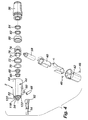
- FIG. 10 is a perspective view showing the exterior of the tube connector 112
- Fig. 11 is a rear plan view of the tube connector 112
- Fig. 12 is a side sectional view of the tube connector 112 taken along plane A-A of Fig. 11 .
- An exemplary embodiment of the tube connector 112 is described below in conjunction with Figs. 10-12 .
- the tube connector 112 shown in Figs. 10-12 is connected to a rear end of the barrel 44 shown in Figs. 3 and 4 . Specifically, when connected, surface 114 of the tube connector 112 abuts against, or is disposed adjacent to, surface 116 of the barrel 114, such that the irrigation fluid coupling 52 of the barrel 44 extends within irrigation fluid entry channel 118, and the suction coupling 54 extends within suction entry channel 120.
- the irrigation fluid coupling 52 and the suction coupling 54 can be formed of an elastic or substantially elastic material, such as rubber, for example, so as to provide a leak-proof or substantially leak-proof fitting within the irrigation fluid entry channel 118 and the suction entry channel 120.
- any method can be used to provide a leak-proof or substantially leak-proof fitting between these elements.
- the irrigation fluid entry channel 118 and the suction entry channel 120 can be formed of an elastic or substantially elastic material, such as rubber, for example, in addition to, or instead of, the irrigation fluid coupling 52 and the suction coupling 54.
- the irrigation fluid coupling 52 and the suction coupling 54 are formed from a rigid material such as aluminum, and rubber O-rings are inserted in channels 118 and 120 to provide a leak-proof fitting. All of these fitting methods provide the advantage of enabling the couplings 52 and 54 to be easily and quickly removed from the channels 118 and 120.
- the couplings 52 and 54 can be permanently or semi-permanently fixed to the channels 118 and 120.
- the irrigation fluid coupling 52 and the suction coupling 54 can be bonded to either interior or exterior walls that define the irrigation fluid entry channel 118 and the suction entry channel 120 by any other method, such as by glue, epoxy, press fitting, melting, or welding, for example.
- the tube connector 112 can be secured to the barrel 44 by any method.
- one or more detents 122 disposed on a periphery of the barrel 44 snap into, or are otherwise engaged with, corresponding apertures 124 defined in the tube connector 112.
- any other method can be used to secure the tube connector 112 to the barrel, such as providing the tube connector 112 with detents that snap into, or are otherwise engaged with, corresponding apertures defined in the barrel 44. Both of these methods provide the advantage of enabling the tube connector 112 to be easily and quickly removed from the barrel 44.
- the tube connector 112 can be permanently or semi-permanently secured to the barrel 44.
- the tube connector 112 can be secured to the barrel 44 by any other method, such as by glue, epoxy, press fitting, melting, or welding, for example.
- the tube connector 112 defines an irrigation fluid projection 126 and a suction projection 128.
- the projections 126 and 128 are formed to be an appropriate size such that the irrigation fluid supply tube 24 can snugly fit inside the irrigation fluid projection 126, and the suction supply tube 30 can snugly fit inside the suction projection 128 and are glued in position so as to provide leak-proof or substantially leak-proof fittings.
- any other method of attachment can be provided between these elements, including push fit attachments which allow the irrigation fluid supply tube and the suction supply tube to be disconnected from the irrigation fluid projection 126 and the suction projection 128.
- the correct orientation of the tube connector 112 is ensured by the angled surface 114, and by the different sizes of the couplings 52 and 54.
- the size of the irrigation fluid coupling 52 matches the size of the irrigation fluid entry channel 118, but not that of the suction entry channel 120.
- the size of the suction coupling 54 matches the size of the suction entry channel 120, but not that of the irrigation fluid entry channel 118.
- the tube connector can be attached to the handpiece in one orientation only.
- the angled surface 114 on the tube connector 112 matches the angled surface 116 on the barrel 44 of the handpiece, again preventing attachment of the tube connector in an incorrect orientation.
- the tube connector 112 enables the irrigation fluid supply tube 24 and the suction supply tube 30 to be connected to the rear end of the handle 2.
- the irrigation fluid supply tube 24 and/or the suction supply tube 30 are not directly connected to the cutting blade assembly 8.
- This structure provides an advantage of enabling the cutting blade assembly 8 or a part thereof to be changed without requiring that the irrigation fluid supply tube 24 and/or the suction supply tube 30 be disconnected from the handle 2, which enhances operation of the apparatus 1.
- This feature is especially advantageous in surgical procedures that require the cutting blade assembly 8 or a part thereof to be changed during the surgical procedure or operation, such as in sinus surgery which may require the use of more than one blade during a single operation or procedure.
- FIG. 13 is a perspective view showing the exterior of the cutting blade assembly 8
- Fig. 14 is a partial perspective view showing a portion of the exterior of the cutting blade assembly 8
- Fig. 15 is a sectional view of the cutting blade assembly 8 taken along plane BB of Fig. 14
- Fig. 16 is a perspective view of the outer hub 138 of the cutting blade assembly 8
- Fig. 17 is side plan view of the outer hub 138 shown in Fig. 16
- Fig. 18 is a sectional view of the outer hub 138 taken along plane CC of Fig. 17
- Fig. 13 is a perspective view showing the exterior of the cutting blade assembly 8
- Fig. 14 is a partial perspective view showing a portion of the exterior of the cutting blade assembly 8
- Fig. 15 is a sectional view of the cutting blade assembly 8 taken along plane BB of Fig. 14
- Fig. 16 is a perspective view of the outer hub 138 of the cutting blade assembly 8
- Fig. 17 is side plan view of the outer hub
- FIG. 19 is a side plan view of an irrigation hole 142 defined in the outer hub 138 shown in Fig. 17 ;
- Fig. 20 is a side plan view of a portion of the outer hub 38 defining retention channels 146 shown in Fig. 17 ;
- Fig. 21 is a sectional view of a portion of the outer hub 138 defining the proximal end 160 shown in Fig. 18 ;
- Fig. 22 is a sectional view of the outer hub 138 taken along plane DD of Fig. 17 ;
- Fig. 23 is a perspective view of the inner hub 162 of the cutting blade assembly 8;
- Fig. 24 is a side plan view of the inner hub 162 shown in Fig. 23;
- FIG. 25 is another side plan view of the inner hub 162 that is rotated 90° relative to the view of Fig. 24; and Fig. 26 is a sectional view of the inner hub 162 taken along plane EE of Fig. 25 .
- An exemplary embodiment of the cutting blade assembly 8 is described below in conjunction with Figs. 13-28 .
- the cutting blade assembly 8 in accordance with the invention can be used to shave, cut and/or remove bodily tissue from a surgical site.
- the invention is intended to cover any structure that can accomplish this and/or other operations.
- Fig. 13 depicts a cutting blade assembly 8 that includes a straight blade structure.
- any other blade structure can be used, such as a bent blade structure, for example, that may provide other advantages, such as providing access to bodily tissue that would be difficult or impossible to reach via a straight blade structure, for example.
- a blade structure can be used that defines a sharp uniform of substantially uniform cutting surface at and/or adjacent to its distal end.
- other cutting surfaces can be used, such as a cutting surface that defines one or more cutting teeth, for example.
- the blade structure does not even have to define a sharp cutting surface, and instead can define another structure, such as a burr, for example, that may provide other advantages, such as facilitating the shaving and/or cutting of muscle and/or bone, for example.
- the cutting blade structure of the cutting blade assembly 8 can be manufactured from rigid material, such as stainless steel, for example.
- the cutting blade can be manufactured from other materials, such as elastic and/or bendable materials for example, that may provide advantages over rigid materials, such as providing enhanced access to certain surgical sites, for example.
- One common arrangement is to provide a flexible shaft, typically of a mesh or wound spring construction, covered by a sealing sleeve.
- an exemplary embodiment is described below that includes a rotating cutting surface.
- any other type of cutting surface can be provided, such as a cutting surface that is linearly movable.
- All or part of the cutting blade assembly 8 can be provided as sterile, and can be sterilised using ethylene oxide gas (EO), for example. All or part of the cutting blade assembly can be placed in a protective tray, that is heat sealed inside a Tyvek and ionomer pouch, which in turn is placed inside of a paperboard carton and shrink-wrapped.
- EO ethylene oxide gas
- the cutting blade assembly 8 includes an inner tube 130 that extends within an outer tube 132.
- a gap 134 is defined between the inner and outer tubes 130 and 132.
- Both the inner and outer tubes 130 and 132 are hollow, such that a distal suction channel 136 is defined within the inner tube 132.
- the distal suction channel 136 communicates with the suction channel 56 shown in Fig. 5 .
- bodily material and/or irrigation fluid can be removed from the surgical site by suction provided to the surgical site via the suction source 28, the suction supply tube 30, the suction channel 56 and the distal suction channel 136.
- the distal suction channel 136 and the suction channel 56 generally extend through a central portion of each of the cutting blade assembly 8 and the upper portion 32 of the handle 2.
- the distal suction channel 136 and the suction channel 56 are generally coaxial with the cutting blade assembly 8 and the upper portion 32 of the handle 2. This enables the bodily material and/or irrigation fluid to be removed along a generally straight path which enhances operation and reduces, minimises or prevents blockages between the surgical site and the suction source 28.
- the invention is intended to cover other methods and structures to remove the bodily material and/or irrigation fluid from the surgical site.
- the distal suction channel 136 and the suction channel 56 do not have to be coaxial with the cutting blade assembly 8 and the upper portion 32 of the handle 2.
- the distal suction channel 136 and the suction channel 56 do not even have to define a straight or substantially straight path between the surgical site and the suction supply tube 30.
- This communication which is discussed in more detail below with regard to other sub-elements of the cutting blade assembly 8, enables irrigation fluid to be supplied to the cutting surface and/or the surgical site via the irrigation fluid source 22 and the irrigation fluid supply tube 24.
- Defining and utilising the gap 134 between the inner and outer tubes 130 and 132 provides a convenient and simple structure to supply irrigation fluid to the cutting surface and/or the surgical site.
- the invention is intended to cover other structures and methods of supplying irrigation fluid to the cutting surface and/or the surgical site.
- the invention is intended to cover an apparatus that does not even utilise irrigation fluid.
- the distal end of the inner tube 130 defines a cutting surface.
- the distal end of the outer tube 132 defines a cutting window, such as an opening, to expose the cutting surface of the inner tube 130 to the bodily tissue to be shaved, cut and/or removed.
- the cutting window can define any sized opening, such as an opening that extends along approximately half of the cross-sectional area of the outer tube 132, for example.
- a cutting opening of this size provides an advantage of enabling a surgeon to expose a significant amount of bodily tissue to the cutting surface of the inner tube 130 while also shielding other tissue that is not to be cut, shaved and/or removed.
- the cutting surface of the inner tube 130 can define a sharp uniform or substantially uniform edge or can have any other appropriate shape, such as a shape defining one or more teeth, for example.
- the walls of the outer tube 132 that define the cutting window can cooperate with the cutting surface of the inner tube 130.
- the outer tube 132 walls can define sharp uniform or substantially uniform edges, or can have any other appropriate shape, such as a shape defining one or more teeth which, in one exemplary embodiment, may cooperate with teeth of the cutting surface of the inner tube 130.
- the inner tube 130 is rotated such that its cutting surface contacts and thereby cuts and/or shaves bodily tissue via the cutting window of the outer tube 132.
- the inner tube 130 is rotated via the motor assembly 38 shown in Fig. 4 .
- the motor assembly 38 can rotate the inner tube 130 at any rotational speed, such as up to 44,000 rpm, for example.
- the communication between the inner tube 130 and the motor assembly 38 is discussed previously in detail with regard to other sub-elements of the cutting blade assembly 8.
- the outer tube 132 is isolated from the inner tube 130 such that the outer tube 132 does not rotate with the inner tube 130. However, the outer tube 132 can be manually rotated by the surgeon via the collet assembly 36 so as to reorient the cutting window.
- the communication between the collet assembly 36 and the outer tube 132 as well as its isolation from the inner blade 130 is discussed in detail previously with regard to other sub-elements of the cutting blade assembly 8.
- the cutting blade assembly also includes an outer hub 138.
- the outer tube 132 extends partially through a longitudinal channel 139, which is defined in the outer hub 138 and shown in Figs. 16 and 18 .
- An exemplary embodiment of the outer hub 138 is more fully shown in Figs. 13-15 with other sub-elements of the cutting blade assembly 8, while Figs. 16-22 exclusively shown the outer hub 138 and sub-elements thereof.
- the outer tube 132 is secured to an interior surface of the outer hub 138 at a location such that the proximal end of the outer tube 132 is distal to a through hole 142, which extends through the outer hub 132 transverse to the longitudinal channel 139. Thus, the outer tube 132 does not extend entirely through the outer hub 138.
- These elements can be secured together by any method, such as by overmoulding, glue, epoxy, press fitting, or welding, for example.
- the outer hub 138 is received within a longitudinal channel defined within the collet assembly 36.
- the proximal end of the outer hub 138 is flared and defines flared guides 140 that communicate with corresponding grooves defined in the interior surface of the collet assembly 36.
- the exterior of the outer hub 138 defines dimples 144 that communicate with retention balls 94, which are shown in Fig. 7 and disposed inside of the collet assembly 36.
- the retention balls 94 are disposed in the dimples 144 and apply a pressing force between an interior surface of the collet assembly 36 and an exterior surface of the outer hub 138 in a direction transverse to longitudinal axis of these elements. As shown in Fig.
- the dimples 144 are substantially uniformly defined around a circumference of the outer hub 138, and are spaced apart from each other at angles of approximately 45°. Disposing the dimples 144 around the circumference of the outer hub 138 provides an advantage of enabling a substantially uniformly distributed pressing force to be applied around the circumference of the outer hub 138.
- any number of one or more dimples 144 and retention balls 94 can be used. Further, if multiple dimples 144 and retention balls 94 are used, the dimples 144 can be spaced apart from each other by any distance.
- the exemplary embodiment shown in the figures provides the dimples 144 at substantially the same longitudinal position around the periphery of the outer hub 138. However, the dimples can be provided at different longitudinal positions along the periphery of the outer hub 138.
- the communication between the above structures enables the outer hub 138 to remain substantially static relative to the collet assembly 36, and in particular enables rotation of the collet assembly 36 to cause a corresponding rotation of the outer hub 138. Further, since the outer tube 132 is secured to the outer hub 138, rotation of the collet assembly 36 causes a corresponding rotation of the outer tube 132, which enables a surgeon to reorient the cutting window.
- the communication between the dimples 144 and the retention balls 94 is advantages in that it provides a rather uniformly distributed transverse pressure over a relatively large surface area of the collet assembly 36 and the outer hub 138.
- other structures can be used to retain the outer hub 138 within the collet assembly 36.
- the exterior of the outer hub 138 can define grooves to communicate with a corresponding structure to provide a pressure fitting between the outer hub 138 and the collet assembly 36.
- the exterior of the outer hub 138 defines retention channels 146 on opposing sides of the through hole 142.
- static O-rings 148 are disposed and held within the retention channels 146.
- a through hole channel 150 is defined by the exterior of the outer hub 138 at substantially the same longitudinal position as the through hole 142.
- a pair of ribs 152 separate the retention channels 146 and corresponding O-rings 148 from the through hole 142 and the through hole channel 150.
- the through hole 142 and the through hole channel 150 are disposed at substantially the same longitudinal position as the transverse channel 60 defined in the barrel 44.
- irrigation fluid flowing distally along the irrigation fluid channel 58 and the transverse channel 60 enters the through hole channel 150 and the through hole 142.
- the irrigation fluid then travels distally along the exterior of the inner tube 130 and the gap 134 defined between the inner and outer tubes 132 and 134 to the cutting window of the outer tube 132.
- the irrigation fluid entering the through hole channel 150 is prevented or substantially prevented from leaking out and traveling longitudinally along the exterior of the outer hub 138 by the static O-rings 148.
- the static O-rings 148 do not have to be used, and any other structure can be provided to prevent or substantially prevent the irrigation fluid from leaking out of the through hole channel 150 and traveling longitudinally along the exterior of the outer hub 138.
- a dynamic O-ring 154 is disposed at a proximal end of the outer hub 138.
- the dynamic O-ring 154 seals the proximal end of the gap 156 defined between the exterior surface of the inner tube 130 and the interior surface of the outer hub 138. This seal prevents or substantially prevents irrigation fluid that has passed down the through hole 142 from traveling proximally along the exterior of the inner blade 130 beyond the proximal end of the outer hub 138.
- the dynamic O-ring 154 is held in place by a donut 158 that is secured to the proximal end 160 of the outer hub 138.
- the donut 158 can be secured to the proximal end of the outer hub 138 by any method, such as by ultrasonic welding. As shown in Fig. 21 , the proximal end 160 can be shaped to enhance acceptance of the donut 158 by ultrasonic welding. However, any other method can be used to secure the donut 158 in place, such as with glue, epoxy, or press fitting, for example.
- the cutting blade assembly 8 also includes an inner hub 162.
- the inner tube 130 extends entirely through a longitudinal channel 164, which is defined in the inner hub 162 and shown in Figs. 23 and 26 .
- An exemplary embodiment of the inner hub 162 is more fully shown in Figs. 23-26 , and sub-elements of the inner hub 162 are shown in Figs. 27 and 27 .
- the inner tube 130 is secured to an interior surface of the inner hub 162, such that proximal end of the inner tube 130 extends beyond the proximal end of the inner hub 162, and the distal end of the inner tube 130 is distal to the distal end of the inner hub 162.
- These elements can be secured together by any method, such as by overmoulding, glue, epoxy, press fitting, or welding, for example.
- the inner hub 162 is received within a longitudinal channel defined within the collet assembly 36 and the barrel 44. Structures that enable the inner hub 162 to be received and held within the collet assembly 36 and the barrel 44 are discussed below.
- the exterior of the inner hub 162 defines an annular hub 165 at its distal end, and a pair of first ribs 166 that extend longitudinally along the inner hub 162.
- the first ribs 166 include drive splines 168 that extend from a position approximately adjacent the proximal end of the inner hub 162 to approximately the longitudinal midpoint of the inner hub 162.
- the first ribs 166 also include spring retention sections 170 that extend from the distal end of the drive splines 168 to the annular hub 165.
- Spring retention projections 172 are defined on the spring retention sections 170 adjacent and spaced from the annular hub 165 so as to define spring retention channels 174 therebetween, an enlarged view of which is shown in Fig. 28 .
- a spring 176 shown in Figs. 13-15 , is retained along the spring retention sections 170. Specifically, a distal end of the spring 176 is held in the spring retention channels 174 between the spring retention projections 172 and the annular hub 165.
- the spring retention projections 172 can be tapered to facilitate insertion of the spring 176.
- the distal end of the drive splines 168 can also serve to hold the proximal end of the spring within the spring retention sections 170.
- the spring 176 provides axial pressure on the inner hub 162 helping to guarantee good contact between the bearing surfaces at the distal end of the shaver blades. In the case of burrs, the same function is performed, but the bearing surface with the pair of washers. The axial force is applied as the blade is engaged. The proximal end of the spring 176 comes into contact with a shoulder machined into the drive shaft. The purpose of this shoulder is to be a positive location for initiating compression of the spring 176. The spring 176 can be compressed 100% in extreme cases with no detrimental effects. In this case, the annular hub 165 of the inner hub 162 will eventually contact the shaft or the distal end of the solid height of the spring.
- the exemplary embodiment discussed above includes a pair of first ribs 166 that are disposed on opposite sides of the circumference of the periphery of the inner hub 162, such that they are spaced approximately 180° from each other.
- This disposition of the first ribs 166 is advantageous in that it provides substantially uniform retention of the spring 176 and provides for substantially uniform operation of the drive splines, which is discussed in more detail below.
- any number of one or more first ribs 166 can be used. Further, if multiple first ribs 166 are used, then they can be spaced any distance from each other around the circumference of the periphery of the inner hub 162.
- first ribs 166 do not have to include the drive splines 168, the spring retention sections 170 and the spring retention projections 172 discussed above. Instead, the first ribs 166 can be any shape and include any structures to retain the spring 176 and perform the operation of the drive splines, which is discussed in more detail below.
- the exterior of the inner hub 162 also defines a pair of second ribs 178.
- the pair of second ribs 178 extend longitudinally and proximally from the annular hub 165 to approximately the longitudinal midpoint of the drive splines 168.
- a proximal end of the second ribs 178 is tapered.
- the drive splines 168 are received within corresponding channels defined in an interior surface of the gear shaft 74, which is rotated by the motor assembly 38, shown in Figs. 4-6 . Receiving the drive splines 168 within the channels of the gear shaft 74 enables the inner hub 162, and thus the inner tube 130 which is served thereto, to be rotated by the motor assembly 38.
- the drive splines 168 are advantageous over some other structures, such as a T-bar arrangement defined at the proximal end of the inner hub 162, in that they provide the inner hub 162 with a relatively large engageable surface area relative to the driving mechanism, i.e., the motor assembly 38 and the gear shaft 74.
- the drive splines 168 are also advantageous in that they provide for an axial tolerance which may facilitate insertion of the inner hub 162 within the barrel 44 and/or provide other benefits.
- the drive splines 168 do not have to be used, and instead any other structure can be provided that enables rotation of the inner hub 162.
- the substantially continuous drive splines 168 shown in the exemplary embodiment can each be replaced with one or more discretely defined blocks, for example.
- the drive splines can be square, triangular lobes, hex drive, etc.
- the cutting blade assembly 8 is intended to be mounted into and secured in the handle 2 in accordance with any acceptable method.
- the cutting blade assembly 8 can be mounted by pulling the collet assembly 36 rearwardly toward the rear of the handle 2, rotating the hub until the key aligns on the chucking mechanism, inserting the inner hub 162 into the handle 2 until it stops completely, releasing the collet assembly 36 and firmly pushing the cutting blade assembly 8 into the handle 2 until the collet assembly 36 springs back into its original position.
- the inner hub 162 begins to engage the spline geometry of the inner diameter of the drive shaft.
- the pair of ribs 140 must be aligned by the operator with any two of the slots present in the fixed lock sleeve 104.
- the retention sleeve must be retracted as described in the application for any of this to be possible. Otherwise, the retention balls will interfere with the outer hub as it is inserted. After inserting the blade fully, releasing the release ring will allow the retention balls to seat into the dimples on the outer hub. These relative locations are defined by the ribs 140.
- the retention sleeve is spring loaded and will return to its locked position upon release. The operator should gently pull on the outer tube of the blade assembly to make sure it is properly retained.
- the cutting blade assembly 8 can similarly be disengaged from the handle 2. This can be accomplished by pulling the collet assembly 36 rearwardly toward the rear of the handle 2, and then pulling the cutting blade assembly 8 out of the handle 2.
- the operator must only retract the retention sleeve and pull on the blade.
- the spring 176 will push the blade assembly out a small amount increasing the amount of outer hub available for handling during removal.
- the cutting blade assembly 8 can be disposable. Thus, after a surgical procedure or operation, the cutting blade assembly 8 can be disengaged from the handle 2 as discussed above and disposed of.
- the handle 2 and other associated or connected elements that are intended on being reused need to be cleaned and sterilised in an acceptable manner.
- An exemplary method of cleaning and sterilisation is discussed below.
- All cleaning should be performed in a manner designed to minimise exposure to blood borne pathogens.
- Reusable medical devices should be kept moist immediately after use until cleaning. Devices capable of disassembly must be disassembled prior to cleaning. Thorough cleaning and rinsing should be carried out as soon as possible. Manual cleaning should be done while the instrument is immersed (if applicable). The purpose of cleaning and rinsing is to remove all adherent visible soil and to reduce particulate matter, microorganisms and pyrogens. Furthermore, thorough rinsing is necessary to remove any residual cleaning agents from the medical devices that could protect microorganisms from destruction and reduce the lethality of the sterilisation process. Medical devices that will be stored between cleaning and decontamination should be dried with low linting, nonabrasive soft cloth to prevent microbial contamination that could result from wet instruments.
- Enzymatic detergents with a pH range between 6.0 and 8.0 should be used. These detergents have nonionic surfactants. Detergents should be used at the concentration level recommend by the manufacturer. Undiluted detergents and ones with pHs greater than 8.0 can strip the coloration from metal instruments.
- the quality of water should be carefully considered for use in preparing enzymatic detergents and for rinsing in the cleaning procedure.
- Water hardness is a concern because deposits left on medical devices may result in ineffective cleaning decontamination.
- Demonised water can help prevent discoloration and staining associated with mineral residues found in tap water.
- the handle 2 and/or associated reusable elements can be cleaned using the exemplary cleaning method as follows:
- the handle can be sterilised by steam sterilisation.
- FIG. 29 is an exploded perspective view of the trigger switch assembly 180 and related sub-elements of the handle 2
- Fig. 30 is a schematic of the sensor strip 192 of the trigger switch assembly 180
- Fig. 31 is a side perspective schematic view of the trigger switch assembly 180 mounted on the handle 2
- Fig. 32 is a front schematic view of the trigger switch assembly 180 mounted on the handle 2.
- An exemplary embodiment of the trigger switch assembly 180 is described below in conjunction with Figs. 2932.
- the trigger switch assembly 180 can be used in lieu of, or in addition to, the footswitch 4 shown in Fig. 1 .
- the trigger switch assembly 180 includes an exterior trigger 182 that is disposed at an exterior of the lower portion 34 (specifically the handle shell 42 shown in Fig. 29 ) of the handle 2.
- the exterior trigger 182 includes a lower annular end cap 184 that is formed to surround the base of the lower portion 34 (specifically the handle shell 42 shown in Fig. 29 ) of the handle 2.
- the end cap 184 can be sized such that the base of the lower portion 34 can be press fitted into the end cap 184 to secure the exterior trigger 182 to the handle 2.
- the exterior trigger 182 also includes an elongated trigger 186. While the lower portion 34 is press fitted to the end cap 184, the elongated trigger 186 extends generally longitudinally along the exterior of the lower portion 34 (specifically the handle shell 42 shown in Fig. 29 ). The bottom of the elongated trigger 186, which is adjacent to the end cap 184, is either in contact with, or disposed close to, the lower portion 34 of the handle 2. However, the elongated trigger 186 is shaped so that it defines an increasing gap with the lower portion 34 of the handle 2 as it extends upwardly toward the upper portion 32 of the handle 2.
- the bottom of the elongated trigger 186 which is adjacent to the end cap 184, forms a fulcrum with regard to the remaining upwardly extending section of the elongated trigger 186.
- a surgeon while grasping the handle 2 as if it was a pistol, can pull an upper section of the elongated trigger 186 toward the lower portion 34 of the handle 2 with one or more of the surgeon's fingers. In this operation, the upper section of the elongated trigger 186 pivots about its bottom.
- lower magnet 188 is disposed at or on an interior surface of the end cap 184, such that the lower magnet 188 is disposed between the interior surface of the end cap 184 and an exterior surface of the bottom of the handle shell 42 of the lower portion 34 of the handle 2.
- An upper magnet 190 is disposed at or on an interior surface of the elongated trigger 186, such that the upper magnet 190 is disposed between the interior surface of the elongated trigger 186 and an exterior surface of the handle shell 42 of the lower portion 34 of the handle 2.
- the lower magnet 188 remains substantially static relative thereto. However, the distance separating the upper magnet 190 and the handle shell 42 as the surgeon presses the elongated trigger 186 toward the handle shell 42 decreases.
- the trigger switch assembly 180 also includes a flexible sensor strip 192 shown in Figs. 29 and 30 .
- the flexible sensor strip 192 includes a rear portion 194, a bottom portion 196, a lower front portion 198, and an upper front portion 200.
- the flexible sensor strip 192 is fixed to the exterior of the handle chassis 40, which is itself disposed inside of the handle shell 42 of the lower portion 34 of the handle 2.
- a strip of insulation tape 202 is attached to the handle chassis 40 so as to extend longitudinally along a rear surface thereof.
- the rear portion 194 of the flexible sensor strip 192 contacts and may be connected to the insulation tape 202 as to aid in securing the flexible sensor strip 192 to the handle chassis 40.
- the bottom of the handle chassis 40 may apply downward pressure to the bottom portion 196 of the flexible sensor strip 192 to also aid in securing the flexible sensor strip 192 to the handle chassis 40.
- a fastener 204 can also be used to further secure the flexible sensor strip 192 to the handle chassis 40 by extending through an aperture 206 defined in the handle chassis 40 and a corresponding aperture 208 defined in the upper front portion 200 of the flexible sensor strip 192.
- the invention is intended to cover any one or more of the above securing methods discussed above.
- the invention is not limited thereto, and any other method of securing the flexible sensor strip 192 to the handle chassis 40 can be used.
- the flexible sensor strip 192 does not even have to be secured to the handle chassis 40.
- the flexible sensor strip 192 can be statically or substantially statically disposed within the handle shell 42 in accordance with any method or structure.
- the flexible sensor strip 192 also includes a lower sensor 210 and an upper sensor 212, which can be Hall sensors that sense a magnetic field.
- the lower sensor 210 is disposed at or on the bottom portion 196 so as to generally oppose the lower magnet 188.
- the upper sensor 212 is disposed at or on the lower front portion 198 so as to generally oppose the upper magnet 190. The operation of the lower and upper sensors 210 and 212 is discussed below.
- the lower magnet 188 While exterior trigger 182 is secured to the handle shell 42, the lower magnet 188 remains in close proximity to the lower sensor 210. In this state, the lower sensor 210 senses the close proximity of the magnetic field of the lower magnet 188. However, if the exterior trigger 182 is removed and/or spaced from the handle shell, the lower sensor 210 fails to sense the magnetic field of the lower magnet 188. Under this circumstance, the lower sensor 210 can provide an output signal indicating that the exterior trigger 182 is not properly secured to the handle shell 42.
- the invention is intended to cover any method of determining whether the exterior trigger 182 is properly secured to the handle shell 42.
- the lower sensor 210 can continuously provide an appropriate output signal, such that cessation of the output signal can be construed as an indication that the exterior trigger 182 is no longer properly secured to the handle shell 42.
- the upper magnet 190 In operation, while the exterior trigger 182 is secured to the handle shell 42, and the surgeon is not actuating the elongated trigger 186, the upper magnet 190 is spaced from the upper sensor 212. However, as the surgeon presses the elongated trigger 186 toward the handle shell 42, the upper magnet 190 moves into close proximity with the upper sensor 212 such that the upper sensor 212 senses its magnetic field. Under this circumstance, the upper sensor 212 can provide an output signal for the purpose of energising the motor assembly 38 to rotate the inner hub 162 and the inner tube 130. Upon the surgeon releasing the elongated trigger 186, the upper magnet 190 moves away from the upper sensor 212 such that the upper sensor 212 no longer senses the magnetic field of the upper magnet 190. Under this circumstance, the upper sensor 212 ceases providing the output signal such that the motor assembly 38 is de-energised.
- the exemplary embodiment of the trigger switch assembly 180 shown in Figs. 29-32 is especially advantageous over other actuating mechanisms, such as a footswitch, since it is easy for a surgeon to operate.
- actuating mechanisms such as a footswitch
- the operation of grasping the handle 2 as a pistol, and pressing the elongated trigger 186 toward the handle shell 42 as if it was the trigger of the pistol, is easier than searching for and depressing a pedal on a footswitch disposed under an operating table.
- any or all of the sub-elements of the trigger switch assembly 180 can be manufactured relatively inexpensively.
- any or all of the sub-elements of the trigger switch assembly 180 can be considered disposable after one or more operations, which makes sterilisation of the apparatus easier and more effective.
- the disposability of any or all of the sub-elements of the trigger switch assembly 180 is enhanced by the fact that the trigger switch assembly 180 is easy to install at the lower portion 34 of the handle 2.
- installing a new trigger switch assembly 180, or a portion thereof, prior to a surgical procedure can be accomplished quickly, easily and/or inexpensively.
- the invention is intended to cover any method of determining whether the surgeon has pressed the elongated trigger 186 toward the handle shell 42 for the purpose of energising/de-energising the motor assembly.
- any or all of the elements discussed above can be replaced with other elements to provide this operation.
- the gap separating the upper section of the elongated trigger 186 can be maintained via a spring or similar compressible mechanism, instead of being maintained by virtue of the shape of the elongated trigger 186.
- the flexible sensor strip 192 does not have to be flexible, and instead can be rigid and preformed into an appropriate shape, such as that shown in Fig. 29 .
- the elongated trigger 186, the upper magnet 190 and the upper sensor 212 can be used to also control the speed of rotation of the motor assembly 38.
- the surgeon gradually releasing pressure on the elongated trigger 186 may cause the upper sensor 212 to provide output signals to decrease the speed of rotation of the motor assembly 38.
- Fig. 33 is a perspective view showing the exterior of an exemplary embodiment of the footswitch 4 in accordance with the invention.
- the exemplary embodiment of the footswitch 4 is described below in conjunction with Fig. 33 .
- the footswitch 4 includes a base 214 which is supported on the floor of the surgical room by feet 216, sides 218 disposed on or above a rear portion of the base 214, and a top 220 disposed on or above the sides 218.
- the foot pedal 12 is movably supported in an upright orientation via a bar assembly 222 that extends through apertures defined in the sides 218.
- a spring or any other mechanism can be used with, or in lieu of, the bar assembly 222 to support the foot pedal 12 in this orientation.
- the foot pedal 12 is operationally connected to a signal generating device (not shown) disposed in the space defined by the sides 218 and the top 220, such that depressing the foot pedal 12 so that it rotates downwardly about the bar assembly 222 causes the signal generating device to generate an input signal to be input to the controller 6 via the footswitch signal line 10.
- the surgeon In operation, the surgeon, after placing the heel or his or her foot on or adjacent to the front of the base 214, depresses the foot pedal 12 with the front and/or toes of the surgeon's foot so that the foot pedal 12 rotates downwardly toward the base 214.
- the signal generating device (not shown) is actuated to provide an appropriate input signal to the controller 6 via the footswitch signal line 10.
- the controller 6 Upon receipt of the appropriate input signal, the controller 6 outputs an output signal to the motor assembly 38 of the handle 2 via the handle signal line 14 to energise the motor assembly 38 and thereby rotate the inner hub 162 and inner tube 130. Releasing the foot pedal 12 enables it to rotate back to its upright orientation, thereby causing the signal generating device to provide an appropriate input signal to the controller 6, which in turn de-energises the motor assembly 38.
- the footswitch 4 can also include a light (not shown).
- the light can be disposed at an appropriate location and be of a sufficient brightness to illuminate all or a part of the footswitch 4. Illuminating the footswitch 4 in this manner is advantageous over non-lighted footswitches, or footswitches that only include LEDs for indicating on/off status, in that it enables the surgeon to more easily find the lighted footswitch 4, which may be disposed among other footswitches and similar devices during surgery or in a surgical room. This advantage is enhanced if the footswitch 4 is provided with a light of a distinctive color, such as blue, for example.
- the base 214 of the footswitch 4 can also define an opening 224 which can be used for a variety of purposes.
- the opening 224 can be used by the surgeon to reorient the footswitch 4, or maintain the surgeon's foot at an appropriate position during operation.
- the opening 224 can also be used to hang the footswitch up in a vertical orientation when not in operation.
- the footswitch 4 can also include a button 225 to perform an operation.
- the button 225 can actuate the creation of an input signal to be input to the controller 6 for the purpose of changing the mode of operation of the cutting blade assembly 8.
- the controller 6 can actuate the motor assembly 38 between a constant mode where the inner hub 162 and the inner tube 130 are rotated at a constant or substantially constant speed, and a variable mode where the inner hub 162 and the inner tube 130 are rotated at a variable speed.
- the invention is not limited to the structure of the footswitch 4 discussed above.
- the invention is intended to cover any method of providing an appropriate input signal to the controller 6 enabling the controller 6 to perform an operation, such as to energise/de-energise the motor assembly 38, for example.
- the footswitch 4 can be used to send other types of input signals to the controller 6 via the footswitch signal line 10.
- the signal generating device may provide the controller 6 with a variable input signal based upon the amount of depression of the foot pedal 12 to vary the speed of rotation of the inner hub 160 and the inner tube 130.
- the irrigation fluid supply tube 24 and the suction supply tube 30 can be provided as integrated strippable twin tubing 226.
- Figs. 34-36 Various views of an exemplary embodiment of the twin tubing are shown in Figs. 34-36 , wherein Fig. 34 is a perspective view of the twin tubing 226 as well as devices connected thereto, Fig. 35 is a perspective view showing a section 236 of the twin tubing 226 in a connected state, and Fig. 36 is a sectional view of the twin tubing 226 taken along plane G-G of Fig. 35 .
- An exemplary embodiment of the twin tubing 226 is discussed below in conjunction with Figs. 34-36 .
- the twin tubing 226 can be disposable. Thus, the twin tubing 226 can be disposed of subsequent to each surgical procedure or operation.
- the irrigation fluid supply tube 24 supplies irrigation fluid from the irrigation fluid source 22, via a vented spike cap 228 and a non-vented irrigation spike 230, to the irrigation fluid entry channel 118 of the tube connector 112 that is provided at the rear end of the upper portion 32 of the handle 2.
- the suction supply tube 30 supplies suction from the suction source 28, via a suction connector 232, to the suction entry channel 120 of the tube connector 112.
- Adhesive 234 can be used to connect the irrigation fluid supply tube 24 to the tube connector 112 and the non-vented irrigation spike 230, as well as the suction supply tube 30 to the tube connector 112 and the suction connector 232.
- the twin tubing 226 can have an integrated tubing portion 236, wherein the irrigation fluid supply tube 24 is connected to the suction supply tube 30 via a connection section 238.
- Figs. 35 and 36 specifically show the integrated tubing portion 236 as well as the connection section 238.
- the integrated tubing portion 236 keeps the irrigation fluid supply tube 24 and the suction supply tube 30 together, which saves space and/or enhances organisation in and/or around the surgical area.
- connection section 238 can be split, separated and/or stripped so as to separate the irrigation fluid supply tube 24 and the suction supply tube 30.
- the tubes 24 and 30 can be separated at or near their ends to facilitate their respective direct or indirect connections to the tube connector 112, irrigation fluid source 22 and suction source 28.
- the tubes 24 and 30 can be separated at any other location or for any other purpose.
- the integrated strippable twin tubing 226 provides advantages as discussed above, the invention is intended to cover any other medium to supply irrigation fluid and suction to the handle 2.
- the tubes 24 and 30 can be either completely separated or completely connected across their entire lengths.
- one or more of the vented spike cap 228, the non-vented irrigation spike 230 and the suction connector 232 can either be obviated or replaced with any appropriate structure to facilitate or accomplish any purpose.
- Figs. 34-36 show the irrigation fluid supply tube 24 as being smaller than the suction supply tube 30. However, the invention is intended to cover each of the tubes 24 and 30 as being any respective size. The irrigation fluid supply tube 24 is also shown as being disposed above the suction supply tube 30. However, the invention is intended to cover any respective orientation between the tubes 24 and 30.
- the irrigation fluid supply tube 24 is manufactured from a deformable material, such as a rubber-based material, for example. This material is advantageous since it facilitates connection to the various devices and enables the use of a simple irrigation fluid supply mechanism 26.
- the irrigation fluid supply tube 24 can be manufactured from any other material, such as a semi-deformable or non-deformable material.
- FIG. 37 is a perspective view showing the front of the irrigation fluid supply mechanism 26
- Fig. 38 is a perspective view showing the rear of the irrigation fluid supply mechanism 26.
- An exemplary embodiment of the irrigation fluid supply mechanism 26 is discussed below in conjunction with Figs. 37 and 38 .
- the exemplary embodiment of the irrigation fluid supply mechanism 26 supplies irrigation fluid from the irrigation fluid source 22, via the irrigation fluid supply tube 24, to the irrigation fluid entry channel 118 of the tube connector 112 that is provided at the rear end of the upper portion 32 of the handle 2 (refer to Figs. 1 and 12 ). As shown in Figs. 37 and 38 , the exemplary embodiment of the irrigation fluid supply mechanism 26 is disposed at or on a side of the controller 6.
- the irrigation fluid supply mechanism 26 does not have to be disposed at this location. Instead, the irrigation fluid supply mechanism can be disposed at any location, such as at or on the irrigation fluid source 22.
- the irrigation fluid supply mechanism 26 defines a tube channel 240 through which the irrigation fluid supply tube 24 extends.
- the tube channel 240 can be an inverted L-shape that includes a horizontal portion and a vertical portion.
- the irrigation fluid supply tube 24 can be inserted into the tube channel 240 via the horizontal portion and ultimately disposed at the bottom of the vertical portion.
- the irrigation fluid supply mechanism 26 also includes a cam 242 that is extendible into the vertical portion of the tube channel 240.
- the cam 242 can increase the pressure of the irrigation fluid supplied to the handle 2 by extending into the vertical portion of the tube channel 240 and contacting the irrigation fluid supply tube 24 disposed therein so as to compress and thereby reduce the opening defined by the inner diameter of the tube 24.
- the cam 242 presses one side of the irrigation fluid supply tube 24 while the opposite side of the tube 24 is held against the bottom surface of the vertical portion of the tube channel 240. Reducing the inner diameter of the irrigation fluid supply tube 24 correspondingly increases the pressure of the irrigation fluid supplied to the handle 2.
- the pressure of the irrigation fluid supplied to the handle 2 can be reduced by moving the cam 242 out of contact with the irrigation fluid supply tube 24 so as to increase its inner diameter.
- the amount of contact pressure provided by the cam 242 to the irrigation fluid supply tube 24 can be varied to supply irrigation fluid to the handle 2 at a specific pressure.
- An embodiment enables the contact pressure, and thus the irrigation fluid supply pressure, to be manually regulated by a knob 244.
- the knob 244 communicates with the cam 242, such that rotating the knob 244 in one direction, such as clockwise, for example, moves the cam 242 downwardly within the vertical portion of the tube channel 240 and into contact with the irrigation fluid supply tube 24, while rotating the knob 244 in the opposite direction, such as counterclockwise, for example, moves the cam 242 upwardly and away from the tube 24.
- the surgeon or member of the surgical team may provide the desired irrigation fluid supply pressure.
- the knob 244 is only used to move the cam 242 out of the way to enable insertion of the irrigation fluid supply 24, and the irrigation fluid supply mechanism 26 is controlled by the controller 6 to provide a desired fluid pressure.
- the exemplary embodiment of the irrigation fluid supply mechanism 26 is described above as utilising a cam mechanism, the invention is intended to cover any method of supplying irrigation fluid to the handle 2.
- the irrigation fluid supply mechanism 26 can be a rotary type peristaltic pump.
- the invention is even intended to cover an apparatus that does not utilise irrigation fluid.
- FIG. 37 is a perspective view showing the front of the controller 6
- Fig. 38 is a perspective view showing the rear of the controller 6.
- An exemplary embodiment of the controller 6 is discussed below in conjunction with Figs. 37 and 38 .
- the controller 6 can be used to receive input signals and/or provide output signals relevant to the operation of the apparatus.
- the controller 6 can be an electronic device to provide this function.
- the power source supply line 18 can be plugged into the rear of the controller 6.
- a source of AC or DC power can be provided to the controller 6 from the power source 16 via the power source supply line 18 to supply power for operation of the controller 6.
- the controller can operate from a source of 100-240 VIC, 50-60 Hz.
- the remote power source 16 can be replaced with a power source that is integral with the controller 6, such as a battery, for example.
- the body of the controller 6 can be made from any material.
- the body of the controller 6 can be molded from flame retardant plastic (synthetic resin).
- the controller 6 can also include a grounding post 246, as well as a serial port 248 for connection to any electronic device.
- a label 253 providing relevant data can also be provided at the rear of the controller 6.
- the controller is vertically mounted in the surgical room at or on a vertical rail 20, such as an IV pole, that extends through a mounting channel 252 defined in the rear of the controller 6.
- An attachment clamp 250 can be provided to secure the controller 6 in place on the vertical rail 20.
- the controller 6 can be movably mounted at or on the vertical rail 20, and may include a handle 254 provided at its upper surface to facilitate an operator manually moving the controller 6 along the vertical rail 20.
- Movably mounting the controller 6 on the vertical rail 20 is advantageous in that it enhances viewability of the controller 6 and may satisfy space constraints.
- the controller 6 does not have to be mounted on the vertical rail 6, and instead can be mounted to anything or anywhere.
- the controller 6 does not even have to be mounted on anything, and can be disposed on the surgical room floor, for example. In fact, the controller 6 can even be disposed remote from the surgical site.
- the front face of the controller 6 can be used to provide various input/output connections, buttons, and displays, for example, which are discussed below.
- the footswitch signal line 10 can be connected to the controller 6 via a footswitch input connector 256, which enables various sub-elements of the footswitch 4, such as the signal generating device, for example, to send and/or receive signals to/from the controller 6.
- the trigger switch assembly 180 is used in lieu of, or in addition to, the footswitch 4, it can similarly be connected to the controller 6.
- Handle input connectors 258 can also be provided for connection of the handle signal line 14 to the controller 6, which enable the controller 6 to send and/or receive signals to/from sub-elements of the handle 2, such as to energise/de-energise the motor assembly 38, and/or to receive identification information to enable the controller 6 to determine the type of handle 2 current being used, which can be provided by an EEPROM.
- Multiple handle input connectors 258 can be provided to enable the connection of multiple handles 2 to the controller 6.
- the front face of the controller 6 can also include a power on/off button 260 to turn the controller 6 on/off. If the type of handle 2 is determined, a display 262 can display the maximum RPM provided by the motor assembly 38 of the identified handle 2. Handle speed adjustment buttons 264 can be provided to increase/reduce the speed of rotation of the inner hub 162 and the inner tube 130.
- Active handle selection buttons 266 can also be provided if multiple handles 2 are connected to the controller 6 via the handle input connectors 258. In this circumstance, pressing either of the active handle selection buttons 266 can select one of the connected handles 2 for operation.
- Another display 268 can also be provided on the front face of the controller 6 to display the actual handle 2 RPM. Specifically, this display 268 indicates the actual or current RPM being provided by the motor assembly 38 to rotate the inner hub 162 and the inner tube 130 of the cutting blade assembly 8.
- Handle operating mode buttons 270 can be provided to change the operating mode of the handle 2.
- these buttons 270 can be used to change the rotation of the inner hub 162 and the inner tube 130 of the cutting blade assembly 8 between a forward direction, a reverse direction, and/or an oscillating type of rotation.
- Footswitch operating mode buttons 272 can also be provided to change the mode of operation of the footswitch 4. For example, these buttons 272 can be used to actuate the footswitch 4 between a constant mode, wherein any depression of the foot pedal 12 results in a constant speed of rotation of the inner hub 162 and the inner tube 130 of the cutting blade assembly 8, and a variable mode, wherein the amount of depression of the foot pedal 12 varies the speed of rotation of the inner hub 162 and the inner tube 130.
- An irrigating pump on/off button 274 can be provided to enable the irrigation fluid supply mechanism 26 to provide irrigation fluid to entry channel 118 of the tube connector 112 at the handle 2, or prevent the supply thereof.
- An irrigation pump flow rate display 276 can be provided to indicate the irrigation fluid flow rate currently being provided by the irrigation fluid supply mechanism 26.
- Irrigation pump flow rate buttons 278 can further be provided in lieu of, or in addition to, the knob 244, to increase/decrease the irrigation fluid flow rate provided by the irrigation fluid supply mechanism 26. If the knob 244 is used in conjunction with the irrigation fluid flow rate buttons 278, the knob 244 may solely be used to move the cam 242 out of the way to enable insertion of the irrigation fluid supply tube 24 into the vertical portion of the tube channel 240, for example.
- An irrigation pump prime button 280 can also be provided to prime the irrigation fluid supply mechanism 26. Specifically, activating this button 280 allows continuous operation of the irrigation fluid supply mechanism 26 to fill all tubing and/or the handle 2 with irrigation fluid to facilitate easy setup of the irrigation fluid supply mechanism 26.
- buttons and displays have been discussed above in the context of the exemplary embodiment of the controller 6 shown in Figs. 37 and 38 .
- the invention is intended to cover any method of performing the functions discussed above.
- the invention is intended to cover any method of providing any relevant function in relation to the surgical apparatus.
- the controller 6 can be configured so as to be divided into two main components, such as a handle motor controller and a coordinating/main controller.
- the handle motor controller can contain an embedded module that implements its particular responsibilities and provides an interface to the main controller.
- the main controller can be responsible for managing the user interface and related device configuration, detecting the presence and type of handle 2 and other peripheral components, and coordinating the response of the handle 2, and the irrigation fluid supply mechanism 26 in response to user input. Because of the simplicity of the device, the main controller can be directly responsible for the control of the irrigation fluid supply mechanism 26.
- the handle controller can be responsible for meeting most of the performance and safety requirements of the handle 2. It can directly control the motor assembly 38 and can interpret high level commands from the main controller into the appropriate signals to provide forward, reverse and oscillating rotation of the motor assembly 38 at the required speed. The handle controller can also be responsible for detecting faults in the motor assembly 38 and responding to them appropriately.
- the connector of the handle assembly may be formed of synthetic resin.
- the invention also provides a handle assembly usable with a movable cutting blade assembly, the handle assembly comprising:
- the trigger switch may include an exterior trigger, the exterior trigger including a lower annular end cap that is engageable with a base of the lower portion to secure the exterior trigger to the lower portion.
- the exterior trigger includes an elongated trigger having one free end and one end connected to the end cap, the exterior trigger extending longitudinally along an exterior of the lower portion such that a gap separating the elongated trigger and the lower portion is greater at the free end than at the end connected to the end cap.
- the lower portion includes a handle shell, a handle chassis disposed within the handle shell, and a motor assembly disposed within the handle chassis.
- the trigger switch may include a sensor strip secured to the handle chassis, and the sensor strip may be flexible.
- the exterior trigger includes a first magnet disposed at the end cap and a second magnet disposed at the elongated trigger spaced from the end cap.
- the sensor strip includes a first sensor opposing the first magnet and a second sensor opposing the second magnet.
- the first and second sensors may be Hall sensors.
- the invention further provides a method of manufacturing a handle assembly that is usable with a movable cutting blade assembly, as a powered surgical apparatus, the method comprising:
- the invention still further provides a cutting blade assembly usable with a handle as a powered surgical apparatus, the handle having an interior surface that defines at least one channel and a motor that rotates the interior surface, the cutting blade assembly comprising:
- the at least one drive spline may be elongated.
- the at least one channel is two channels, and the at least one drive spline is two splines that are disposed on opposite sides of the inner hub.
- the at least one drive spline extends distally along the exterior of the inner hub from a location adjacent to a proximal end of the inner hub, the inner hub defining an annular hub at a distal end of the inner hub.
- This cutting blade assembly may further comprise a spring, wherein the inner hub defines at least one spring retention projection spaced from the annular hub so as to define at least one spring retention channel therebetween, one end of the spring being retained within the at least one spring retention channel and an opposite end of the spring being retained by a distal end of the at least one drive spline.
- the inner hub and the outer hub are formed from synthetic resin, or from metal.
- the invention also provides a cutting blade assembly usable with a handle as a powered surgical apparatus, the handle including a manually-rotatable collet assembly and at least one retention ball, the cutting blade assembly comprising:
- the at least one dimple may be at least one semi-spherical indentation in the exterior of the outer hub, and the at least one retention ball is at least one sphere.
- the at least one detent includes multiple detents equidistantly spaced around an outer circumference of the outer hub.
- the outer hub may have a tapered distal end.
- an interior surface of a distal section of the collet assembly defines at least one channel, the exterior surface of the outer hub defining at least one elongated projection that communicates with the at least one channel.
- the at least one elongated projection may include two elongated projections that are spaced on opposite sides of the exterior of the outer hub.
- the invention still further provides a method of manufacturing a cutting blade assembly usable with a handle as a powered surgical apparatus, the handle having an interior surface that defines at least one channel and a motor that rotates the interior surface, the method comprising:
- the invention still further provides a method of manufacturing a cutting blade assembly usable with a handle as a powered surgical apparatus, the handle including a manually-rotatable collet assembly and at least one retention ball, the method comprising:
- the invention also provides a cutting blade assembly usable with a handle and a source of irrigation fluid as a powered surgical apparatus, the handle including a barrel that defines an irrigation fluid channel, the irrigation fluid channel including a longitudinal section and a transverse section, the cutting blade assembly comprising:
- the outer hub may define a circumferentially-extending through hole channel at the transverse through hole and circumferentially-extending O-ring retention channels on opposite sides of the through hole channel, the O-ring retention channels being separated from the through hole channel by a pair of circumferentially-extending ribs.
- This cutting blade assembly may further comprise O-rings disposed in the O-ring retention channels.
- the O-rings are sized to seal a gap separating the exterior of the outer hub and an interior surface of the barrel.
- This cutting blade assembly may further comprise a dynamic O-ring and a donut securing the dynamic O-ring to a proximal end of the outer hub, the dynamic O-ring sealing the gap separating the exterior of the inner tube and the interior of the outer hub.
- the donut is secured to the proximal end of the outer hub by ultrasonic welding.
- the inner hub and the outer hub are formed from synthetic resin, or from metal.
- the invention further provides a method of manufacturing a cutting blade assembly usable with a handle and a source of irrigation fluid as a powered surgical apparatus, the handle including a barrel that defines an irrigation fluid channel, the irrigation fluid channel including a longitudinal section and a transverse section, the method comprising:
- the invention still further provides a powered surgical apparatus system for use with a source of irrigation fluid and a source of suction, the system comprising:
- the manually-actuable input device may be a footswitch, or a trigger switch assembly disposed at the handle.
- the invention also provides a collet assembly usable with a powered surgical apparatus that includes a handle and a movable cutting blade assembly that includes an outer hub secured to an outer tube that defines a cutting window, the collet assembly comprising:
- the at least one groove of the sliding cam may include two grooves.
- the at least one groove of the sliding cam is V-shaped.
- the retention sleeve includes a flange that is trapped in a gap defined between the stationary cam and the base mount, the retention sleeve being rotatable relative to the stationary cam and the base mount.
- the retention sleeve defines at least one key that communicates with at least one interior groove of the sliding cam so as to secure the sliding cam to the retention sleeve.
- This collet assembly may further comprise a spring that applies a pressing force to the sliding cam such that the teeth of the sliding cam are engaged with the teeth of the stationary cam preventing relative rotation therebetween unless the swivel shell is rotated to overcome the pressing force and thereby disengage the teeth of the sliding cam from the teeth of the stationary cam.
Applications Claiming Priority (4)
| Application Number | Priority Date | Filing Date | Title |
|---|---|---|---|
| US36622402P | 2002-03-22 | 2002-03-22 | |
| US10/103,104 US7247161B2 (en) | 2002-03-22 | 2002-03-22 | Powered surgical apparatus, method of manufacturing powered surgical apparatus, and method of using powered surgical apparatus |
| EP03704774A EP1487359B1 (fr) | 2002-03-22 | 2003-02-10 | Appareil chirurgical a fonctionnement electrique |
| EP07075181A EP1803406B1 (fr) | 2002-03-22 | 2003-02-10 | Ensemble de poignée pour appareil chirurgical électrique |
Related Parent Applications (2)
| Application Number | Title | Priority Date | Filing Date |
|---|---|---|---|
| EP03704774.3 Division | 2003-02-10 | ||
| EP07075181.3 Division | 2007-03-12 |
Publications (2)
| Publication Number | Publication Date |
|---|---|
| EP2340774A2 true EP2340774A2 (fr) | 2011-07-06 |
| EP2340774A3 EP2340774A3 (fr) | 2011-11-30 |
Family
ID=28456586
Family Applications (5)
| Application Number | Title | Priority Date | Filing Date |
|---|---|---|---|
| EP07075181A Expired - Lifetime EP1803406B1 (fr) | 2002-03-22 | 2003-02-10 | Ensemble de poignée pour appareil chirurgical électrique |
| EP03704774A Expired - Lifetime EP1487359B1 (fr) | 2002-03-22 | 2003-02-10 | Appareil chirurgical a fonctionnement electrique |
| EP10179304.0A Expired - Lifetime EP2292163B1 (fr) | 2002-03-22 | 2003-02-10 | Appareil chirurgical électrique et procédé pour la fabrication d'un appareil chirurgical électrique |
| EP10179404.8A Expired - Lifetime EP2292164B1 (fr) | 2002-03-22 | 2003-02-10 | Appareil chirurgical électrique et procédé pour la fabrication d'un appareil chirurgical électrique |
| EP10180362A Withdrawn EP2340774A3 (fr) | 2002-03-22 | 2003-02-10 | Appareil chirurgical électrique et procédé pour la fabrication d'un appareil chirurgical électrique |
Family Applications Before (4)
| Application Number | Title | Priority Date | Filing Date |
|---|---|---|---|
| EP07075181A Expired - Lifetime EP1803406B1 (fr) | 2002-03-22 | 2003-02-10 | Ensemble de poignée pour appareil chirurgical électrique |
| EP03704774A Expired - Lifetime EP1487359B1 (fr) | 2002-03-22 | 2003-02-10 | Appareil chirurgical a fonctionnement electrique |
| EP10179304.0A Expired - Lifetime EP2292163B1 (fr) | 2002-03-22 | 2003-02-10 | Appareil chirurgical électrique et procédé pour la fabrication d'un appareil chirurgical électrique |
| EP10179404.8A Expired - Lifetime EP2292164B1 (fr) | 2002-03-22 | 2003-02-10 | Appareil chirurgical électrique et procédé pour la fabrication d'un appareil chirurgical électrique |
Country Status (10)
| Country | Link |
|---|---|
| US (8) | US7247161B2 (fr) |
| EP (5) | EP1803406B1 (fr) |
| JP (2) | JP4394458B2 (fr) |
| CN (2) | CN1301087C (fr) |
| AT (2) | ATE503430T1 (fr) |
| AU (1) | AU2003207302B2 (fr) |
| BR (1) | BR0308648A (fr) |
| DE (2) | DE60336601D1 (fr) |
| ES (1) | ES2292935T3 (fr) |
| WO (1) | WO2003079911A1 (fr) |
Families Citing this family (797)
| Publication number | Priority date | Publication date | Assignee | Title |
|---|---|---|---|---|
| US11229472B2 (en) | 2001-06-12 | 2022-01-25 | Cilag Gmbh International | Modular battery powered handheld surgical instrument with multiple magnetic position sensors |
| US8599250B2 (en) * | 2002-03-12 | 2013-12-03 | Karl Storz Imaging, Inc. | Wireless camera coupling |
| US9510740B2 (en) * | 2002-03-12 | 2016-12-06 | Karl Storz Endovision, Inc. | Auto recognition of a shaver blade for medical use |
| US8723936B2 (en) | 2002-03-12 | 2014-05-13 | Karl Storz Imaging, Inc. | Wireless camera coupling with rotatable coupling |
| US8194122B2 (en) * | 2002-03-12 | 2012-06-05 | Karl Storz Imaging, Inc. | Universal scope reader |
| US7247161B2 (en) * | 2002-03-22 | 2007-07-24 | Gyrus Ent L.L.C. | Powered surgical apparatus, method of manufacturing powered surgical apparatus, and method of using powered surgical apparatus |
| EP1380265A1 (fr) * | 2002-07-11 | 2004-01-14 | Olympus Optical Corporation Limited | Appareil pour le traitement de calculs |
| US6929619B2 (en) * | 2002-08-02 | 2005-08-16 | Liebel-Flarshiem Company | Injector |
| US8100823B2 (en) * | 2002-09-27 | 2012-01-24 | Surgitech, Llc | Surgical file system with a visualization instrument |
| US7794408B2 (en) * | 2003-03-28 | 2010-09-14 | Ethicon, Inc. | Tissue collection device and methods |
| US20070084897A1 (en) | 2003-05-20 | 2007-04-19 | Shelton Frederick E Iv | Articulating surgical stapling instrument incorporating a two-piece e-beam firing mechanism |
| US9060770B2 (en) | 2003-05-20 | 2015-06-23 | Ethicon Endo-Surgery, Inc. | Robotically-driven surgical instrument with E-beam driver |
| US20040254588A1 (en) * | 2003-06-10 | 2004-12-16 | Kim Yong Seong | Skincare apparatus |
| US7611473B2 (en) | 2003-09-11 | 2009-11-03 | Ethicon, Inc. | Tissue extraction and maceration device |
| US8034003B2 (en) | 2003-09-11 | 2011-10-11 | Depuy Mitek, Inc. | Tissue extraction and collection device |
| US10041822B2 (en) | 2007-10-05 | 2018-08-07 | Covidien Lp | Methods to shorten calibration times for powered devices |
| US9113880B2 (en) * | 2007-10-05 | 2015-08-25 | Covidien Lp | Internal backbone structural chassis for a surgical device |
| US9055943B2 (en) | 2007-09-21 | 2015-06-16 | Covidien Lp | Hand held surgical handle assembly, surgical adapters for use between surgical handle assembly and surgical end effectors, and methods of use |
| US8182501B2 (en) | 2004-02-27 | 2012-05-22 | Ethicon Endo-Surgery, Inc. | Ultrasonic surgical shears and method for sealing a blood vessel using same |
| WO2005094283A2 (fr) * | 2004-03-25 | 2005-10-13 | Hauser David L | Dispositif de filtrage vasculaire |
| US8277474B2 (en) * | 2004-05-26 | 2012-10-02 | Medtronic, Inc. | Surgical cutting instrument |
| US8905977B2 (en) | 2004-07-28 | 2014-12-09 | Ethicon Endo-Surgery, Inc. | Surgical stapling instrument having an electroactive polymer actuated medical substance dispenser |
| US11890012B2 (en) | 2004-07-28 | 2024-02-06 | Cilag Gmbh International | Staple cartridge comprising cartridge body and attached support |
| US8215531B2 (en) | 2004-07-28 | 2012-07-10 | Ethicon Endo-Surgery, Inc. | Surgical stapling instrument having a medical substance dispenser |
| US7226460B2 (en) | 2004-08-02 | 2007-06-05 | Karl Storz Endovision, Inc. | Surgical instrument attachment system |
| US8657808B2 (en) * | 2004-08-31 | 2014-02-25 | Medtronic, Inc. | Surgical apparatus including a hand-activated, cable assembly and method of using same |
| US7598696B2 (en) | 2004-08-31 | 2009-10-06 | Medtronic, Inc. | Surgical apparatus including a hand-activated, control assembly and method of using same |
| EP1802245B8 (fr) | 2004-10-08 | 2016-09-28 | Ethicon Endo-Surgery, LLC | Instrument chirurgical ultrasonique |
| US8628534B2 (en) * | 2005-02-02 | 2014-01-14 | DePuy Synthes Products, LLC | Ultrasonic cutting device |
| AU2005332279A1 (en) * | 2005-05-25 | 2006-11-30 | Synthes Gmbh | Device for controlled operation of a surgical or dental drive unit |
| US9237891B2 (en) | 2005-08-31 | 2016-01-19 | Ethicon Endo-Surgery, Inc. | Robotically-controlled surgical stapling devices that produce formed staples having different lengths |
| US8800838B2 (en) | 2005-08-31 | 2014-08-12 | Ethicon Endo-Surgery, Inc. | Robotically-controlled cable-based surgical end effectors |
| US7669746B2 (en) | 2005-08-31 | 2010-03-02 | Ethicon Endo-Surgery, Inc. | Staple cartridges for forming staples having differing formed staple heights |
| US7673781B2 (en) | 2005-08-31 | 2010-03-09 | Ethicon Endo-Surgery, Inc. | Surgical stapling device with staple driver that supports multiple wire diameter staples |
| US7934630B2 (en) | 2005-08-31 | 2011-05-03 | Ethicon Endo-Surgery, Inc. | Staple cartridges for forming staples having differing formed staple heights |
| US10159482B2 (en) | 2005-08-31 | 2018-12-25 | Ethicon Llc | Fastener cartridge assembly comprising a fixed anvil and different staple heights |
| US11246590B2 (en) | 2005-08-31 | 2022-02-15 | Cilag Gmbh International | Staple cartridge including staple drivers having different unfired heights |
| US11484312B2 (en) | 2005-08-31 | 2022-11-01 | Cilag Gmbh International | Staple cartridge comprising a staple driver arrangement |
| US8991676B2 (en) | 2007-03-15 | 2015-03-31 | Ethicon Endo-Surgery, Inc. | Surgical staple having a slidable crown |
| US20070191713A1 (en) | 2005-10-14 | 2007-08-16 | Eichmann Stephen E | Ultrasonic device for cutting and coagulating |
| US20070106317A1 (en) | 2005-11-09 | 2007-05-10 | Shelton Frederick E Iv | Hydraulically and electrically actuated articulation joints for surgical instruments |
| US7621930B2 (en) | 2006-01-20 | 2009-11-24 | Ethicon Endo-Surgery, Inc. | Ultrasound medical instrument having a medical ultrasonic blade |
| US8763879B2 (en) | 2006-01-31 | 2014-07-01 | Ethicon Endo-Surgery, Inc. | Accessing data stored in a memory of surgical instrument |
| US20110024477A1 (en) | 2009-02-06 | 2011-02-03 | Hall Steven G | Driven Surgical Stapler Improvements |
| US7845537B2 (en) | 2006-01-31 | 2010-12-07 | Ethicon Endo-Surgery, Inc. | Surgical instrument having recording capabilities |
| US11278279B2 (en) | 2006-01-31 | 2022-03-22 | Cilag Gmbh International | Surgical instrument assembly |
| US11793518B2 (en) | 2006-01-31 | 2023-10-24 | Cilag Gmbh International | Powered surgical instruments with firing system lockout arrangements |
| US8708213B2 (en) | 2006-01-31 | 2014-04-29 | Ethicon Endo-Surgery, Inc. | Surgical instrument having a feedback system |
| US20120292367A1 (en) | 2006-01-31 | 2012-11-22 | Ethicon Endo-Surgery, Inc. | Robotically-controlled end effector |
| US20110295295A1 (en) | 2006-01-31 | 2011-12-01 | Ethicon Endo-Surgery, Inc. | Robotically-controlled surgical instrument having recording capabilities |
| US9861359B2 (en) | 2006-01-31 | 2018-01-09 | Ethicon Llc | Powered surgical instruments with firing system lockout arrangements |
| US11224427B2 (en) | 2006-01-31 | 2022-01-18 | Cilag Gmbh International | Surgical stapling system including a console and retraction assembly |
| US8820603B2 (en) | 2006-01-31 | 2014-09-02 | Ethicon Endo-Surgery, Inc. | Accessing data stored in a memory of a surgical instrument |
| US8186555B2 (en) | 2006-01-31 | 2012-05-29 | Ethicon Endo-Surgery, Inc. | Motor-driven surgical cutting and fastening instrument with mechanical closure system |
| US8161977B2 (en) | 2006-01-31 | 2012-04-24 | Ethicon Endo-Surgery, Inc. | Accessing data stored in a memory of a surgical instrument |
| US7753904B2 (en) | 2006-01-31 | 2010-07-13 | Ethicon Endo-Surgery, Inc. | Endoscopic surgical instrument with a handle that can articulate with respect to the shaft |
| GB0602469D0 (en) * | 2006-02-07 | 2006-03-22 | Orthomedex Ltd | Method of manufacturing electrically powered surgicalinstruments, and electrically powered surgical instruments manufactured thereby |
| US8992422B2 (en) | 2006-03-23 | 2015-03-31 | Ethicon Endo-Surgery, Inc. | Robotically-controlled endoscopic accessory channel |
| US8236010B2 (en) | 2006-03-23 | 2012-08-07 | Ethicon Endo-Surgery, Inc. | Surgical fastener and cutter with mimicking end effector |
| CA2653976A1 (fr) * | 2006-06-01 | 2007-12-13 | Osteo Innovations, Llc | Dispositif, systeme et methode de traitement vertebral |
| US8574252B2 (en) | 2006-06-01 | 2013-11-05 | Ethicon Endo-Surgery, Inc. | Ultrasonic blade support |
| US8322455B2 (en) | 2006-06-27 | 2012-12-04 | Ethicon Endo-Surgery, Inc. | Manually driven surgical cutting and fastening instrument |
| US7740159B2 (en) | 2006-08-02 | 2010-06-22 | Ethicon Endo-Surgery, Inc. | Pneumatically powered surgical cutting and fastening instrument with a variable control of the actuating rate of firing with mechanical power assist |
| US10568652B2 (en) | 2006-09-29 | 2020-02-25 | Ethicon Llc | Surgical staples having attached drivers of different heights and stapling instruments for deploying the same |
| US8220690B2 (en) | 2006-09-29 | 2012-07-17 | Ethicon Endo-Surgery, Inc. | Connected surgical staples and stapling instruments for deploying the same |
| US10130359B2 (en) | 2006-09-29 | 2018-11-20 | Ethicon Llc | Method for forming a staple |
| US20110087276A1 (en) | 2009-10-09 | 2011-04-14 | Ethicon Endo-Surgery, Inc. | Method for forming a staple |
| US8647349B2 (en) | 2006-10-18 | 2014-02-11 | Hologic, Inc. | Systems for performing gynecological procedures with mechanical distension |
| US20080146872A1 (en) | 2006-11-07 | 2008-06-19 | Gruber William H | Mechanical distension systems for performing a medical procedure in a remote space |
| US8025656B2 (en) | 2006-11-07 | 2011-09-27 | Hologic, Inc. | Methods, systems and devices for performing gynecological procedures |
| EP2094167B1 (fr) * | 2006-11-30 | 2011-06-29 | Wilson-Cook Medical, Inc. | Ancres viscérales pour la fermeture en bourse de perforations |
| US7682360B2 (en) * | 2006-12-07 | 2010-03-23 | Tyco Healthcare Group Lp | Bipolar tissue debrider and method |
| US9326665B2 (en) | 2007-01-09 | 2016-05-03 | Medtronic Xomed, Inc. | Surgical instrument, system, and method for biofilm removal |
| US8206349B2 (en) | 2007-03-01 | 2012-06-26 | Medtronic Xomed, Inc. | Systems and methods for biofilm removal, including a biofilm removal endoscope for use therewith |
| US20080167527A1 (en) | 2007-01-09 | 2008-07-10 | Slenker Dale E | Surgical systems and methods for biofilm removal, including a sheath for use therewith |
| US11291441B2 (en) | 2007-01-10 | 2022-04-05 | Cilag Gmbh International | Surgical instrument with wireless communication between control unit and remote sensor |
| US8684253B2 (en) | 2007-01-10 | 2014-04-01 | Ethicon Endo-Surgery, Inc. | Surgical instrument with wireless communication between a control unit of a robotic system and remote sensor |
| US8652120B2 (en) | 2007-01-10 | 2014-02-18 | Ethicon Endo-Surgery, Inc. | Surgical instrument with wireless communication between control unit and sensor transponders |
| US8459520B2 (en) | 2007-01-10 | 2013-06-11 | Ethicon Endo-Surgery, Inc. | Surgical instrument with wireless communication between control unit and remote sensor |
| US20080169332A1 (en) | 2007-01-11 | 2008-07-17 | Shelton Frederick E | Surgical stapling device with a curved cutting member |
| US11039836B2 (en) | 2007-01-11 | 2021-06-22 | Cilag Gmbh International | Staple cartridge for use with a surgical stapling instrument |
| DE502007005829D1 (de) * | 2007-01-17 | 2011-01-13 | W & H Dentalwerk Buermoos Gmbh | Medizinischer Handgriff |
| US8057498B2 (en) | 2007-11-30 | 2011-11-15 | Ethicon Endo-Surgery, Inc. | Ultrasonic surgical instrument blades |
| US8911460B2 (en) | 2007-03-22 | 2014-12-16 | Ethicon Endo-Surgery, Inc. | Ultrasonic surgical instruments |
| US20080234709A1 (en) | 2007-03-22 | 2008-09-25 | Houser Kevin L | Ultrasonic surgical instrument and cartilage and bone shaping blades therefor |
| US8142461B2 (en) | 2007-03-22 | 2012-03-27 | Ethicon Endo-Surgery, Inc. | Surgical instruments |
| US8226675B2 (en) | 2007-03-22 | 2012-07-24 | Ethicon Endo-Surgery, Inc. | Surgical instruments |
| US8893946B2 (en) | 2007-03-28 | 2014-11-25 | Ethicon Endo-Surgery, Inc. | Laparoscopic tissue thickness and clamp load measuring devices |
| US9259233B2 (en) | 2007-04-06 | 2016-02-16 | Hologic, Inc. | Method and device for distending a gynecological cavity |
| US8574253B2 (en) | 2007-04-06 | 2013-11-05 | Hologic, Inc. | Method, system and device for tissue removal |
| US20090270895A1 (en) * | 2007-04-06 | 2009-10-29 | Interlace Medical, Inc. | Low advance ratio, high reciprocation rate tissue removal device |
| US9095366B2 (en) | 2007-04-06 | 2015-08-04 | Hologic, Inc. | Tissue cutter with differential hardness |
| US9050123B2 (en) * | 2007-04-16 | 2015-06-09 | Smith & Nephew, Inc. | Powered surgical system |
| USD767353S1 (en) | 2007-05-22 | 2016-09-27 | Ethicon Endo-Surgery, Llc | Torque wrench for ultrasonic instrument |
| US8157145B2 (en) | 2007-05-31 | 2012-04-17 | Ethicon Endo-Surgery, Inc. | Pneumatically powered surgical cutting and fastening instrument with electrical feedback |
| US7832408B2 (en) | 2007-06-04 | 2010-11-16 | Ethicon Endo-Surgery, Inc. | Surgical instrument having a directional switching mechanism |
| US8534528B2 (en) | 2007-06-04 | 2013-09-17 | Ethicon Endo-Surgery, Inc. | Surgical instrument having a multiple rate directional switching mechanism |
| US8931682B2 (en) | 2007-06-04 | 2015-01-13 | Ethicon Endo-Surgery, Inc. | Robotically-controlled shaft based rotary drive systems for surgical instruments |
| US11857181B2 (en) | 2007-06-04 | 2024-01-02 | Cilag Gmbh International | Robotically-controlled shaft based rotary drive systems for surgical instruments |
| US7905380B2 (en) | 2007-06-04 | 2011-03-15 | Ethicon Endo-Surgery, Inc. | Surgical instrument having a multiple rate directional switching mechanism |
| US8308040B2 (en) | 2007-06-22 | 2012-11-13 | Ethicon Endo-Surgery, Inc. | Surgical stapling instrument with an articulatable end effector |
| US7753245B2 (en) | 2007-06-22 | 2010-07-13 | Ethicon Endo-Surgery, Inc. | Surgical stapling instruments |
| US11849941B2 (en) | 2007-06-29 | 2023-12-26 | Cilag Gmbh International | Staple cartridge having staple cavities extending at a transverse angle relative to a longitudinal cartridge axis |
| US8523889B2 (en) | 2007-07-27 | 2013-09-03 | Ethicon Endo-Surgery, Inc. | Ultrasonic end effectors with increased active length |
| US8882791B2 (en) | 2007-07-27 | 2014-11-11 | Ethicon Endo-Surgery, Inc. | Ultrasonic surgical instruments |
| US8808319B2 (en) | 2007-07-27 | 2014-08-19 | Ethicon Endo-Surgery, Inc. | Surgical instruments |
| US8430898B2 (en) | 2007-07-31 | 2013-04-30 | Ethicon Endo-Surgery, Inc. | Ultrasonic surgical instruments |
| US8252012B2 (en) | 2007-07-31 | 2012-08-28 | Ethicon Endo-Surgery, Inc. | Ultrasonic surgical instrument with modulator |
| US9044261B2 (en) | 2007-07-31 | 2015-06-02 | Ethicon Endo-Surgery, Inc. | Temperature controlled ultrasonic surgical instruments |
| US8512365B2 (en) | 2007-07-31 | 2013-08-20 | Ethicon Endo-Surgery, Inc. | Surgical instruments |
| US9023014B2 (en) * | 2007-09-21 | 2015-05-05 | Covidien Lp | Quick connect assembly for use between surgical handle assembly and surgical accessories |
| CN101883531B (zh) * | 2007-10-05 | 2014-07-02 | 伊西康内外科公司 | 人体工程学外科手术器械 |
| US20110022032A1 (en) * | 2007-10-05 | 2011-01-27 | Tyco Healthcare Group Lp | Battery ejection design for a surgical device |
| US20090099660A1 (en) * | 2007-10-10 | 2009-04-16 | Warsaw Orthopedic, Inc. | Instrumentation to Facilitate Access into the Intervertebral Disc Space and Introduction of Materials Therein |
| US8906053B2 (en) * | 2007-11-12 | 2014-12-09 | Medtronic Xomed, Inc. | Systems and methods for surgical removal of brain tumors |
| US8262645B2 (en) | 2007-11-21 | 2012-09-11 | Actuated Medical, Inc. | Devices for clearing blockages in in-situ artificial lumens |
| US10010339B2 (en) | 2007-11-30 | 2018-07-03 | Ethicon Llc | Ultrasonic surgical blades |
| US7905381B2 (en) | 2008-09-19 | 2011-03-15 | Ethicon Endo-Surgery, Inc. | Surgical stapling instrument with cutting member arrangement |
| US7766209B2 (en) | 2008-02-13 | 2010-08-03 | Ethicon Endo-Surgery, Inc. | Surgical stapling instrument with improved firing trigger arrangement |
| US8561870B2 (en) | 2008-02-13 | 2013-10-22 | Ethicon Endo-Surgery, Inc. | Surgical stapling instrument |
| US8540133B2 (en) | 2008-09-19 | 2013-09-24 | Ethicon Endo-Surgery, Inc. | Staple cartridge |
| US8453908B2 (en) | 2008-02-13 | 2013-06-04 | Ethicon Endo-Surgery, Inc. | Surgical stapling instrument with improved firing trigger arrangement |
| US7866527B2 (en) | 2008-02-14 | 2011-01-11 | Ethicon Endo-Surgery, Inc. | Surgical stapling apparatus with interlockable firing system |
| US8657174B2 (en) | 2008-02-14 | 2014-02-25 | Ethicon Endo-Surgery, Inc. | Motorized surgical cutting and fastening instrument having handle based power source |
| US8459525B2 (en) | 2008-02-14 | 2013-06-11 | Ethicon Endo-Sugery, Inc. | Motorized surgical cutting and fastening instrument having a magnetic drive train torque limiting device |
| US8584919B2 (en) | 2008-02-14 | 2013-11-19 | Ethicon Endo-Sugery, Inc. | Surgical stapling apparatus with load-sensitive firing mechanism |
| US9179912B2 (en) | 2008-02-14 | 2015-11-10 | Ethicon Endo-Surgery, Inc. | Robotically-controlled motorized surgical cutting and fastening instrument |
| US7793812B2 (en) | 2008-02-14 | 2010-09-14 | Ethicon Endo-Surgery, Inc. | Disposable motor-driven loading unit for use with a surgical cutting and stapling apparatus |
| US8622274B2 (en) | 2008-02-14 | 2014-01-07 | Ethicon Endo-Surgery, Inc. | Motorized cutting and fastening instrument having control circuit for optimizing battery usage |
| US8636736B2 (en) | 2008-02-14 | 2014-01-28 | Ethicon Endo-Surgery, Inc. | Motorized surgical cutting and fastening instrument |
| US8758391B2 (en) | 2008-02-14 | 2014-06-24 | Ethicon Endo-Surgery, Inc. | Interchangeable tools for surgical instruments |
| US8752749B2 (en) | 2008-02-14 | 2014-06-17 | Ethicon Endo-Surgery, Inc. | Robotically-controlled disposable motor-driven loading unit |
| BRPI0901282A2 (pt) | 2008-02-14 | 2009-11-17 | Ethicon Endo Surgery Inc | instrumento cirúrgico de corte e fixação dotado de eletrodos de rf |
| US8573465B2 (en) | 2008-02-14 | 2013-11-05 | Ethicon Endo-Surgery, Inc. | Robotically-controlled surgical end effector system with rotary actuated closure systems |
| US7819298B2 (en) | 2008-02-14 | 2010-10-26 | Ethicon Endo-Surgery, Inc. | Surgical stapling apparatus with control features operable with one hand |
| US20090206131A1 (en) | 2008-02-15 | 2009-08-20 | Ethicon Endo-Surgery, Inc. | End effector coupling arrangements for a surgical cutting and stapling instrument |
| US20090206126A1 (en) | 2008-02-15 | 2009-08-20 | Ethicon Endo-Surgery, Inc. | Buttress material with alignment and retention features for use with surgical end effectors |
| US11272927B2 (en) | 2008-02-15 | 2022-03-15 | Cilag Gmbh International | Layer arrangements for surgical staple cartridges |
| US8608044B2 (en) | 2008-02-15 | 2013-12-17 | Ethicon Endo-Surgery, Inc. | Feedback and lockout mechanism for surgical instrument |
| US10390823B2 (en) | 2008-02-15 | 2019-08-27 | Ethicon Llc | End effector comprising an adjunct |
| US20090270894A1 (en) * | 2008-04-25 | 2009-10-29 | Joshua David Rubin | Surgical instrument with internal irrigation |
| US9827367B2 (en) | 2008-04-29 | 2017-11-28 | Medtronic Xomed, Inc. | Surgical instrument, system, and method for frontal sinus irrigation |
| US8058771B2 (en) | 2008-08-06 | 2011-11-15 | Ethicon Endo-Surgery, Inc. | Ultrasonic device for cutting and coagulating with stepped output |
| US9089360B2 (en) | 2008-08-06 | 2015-07-28 | Ethicon Endo-Surgery, Inc. | Devices and techniques for cutting and coagulating tissue |
| US8083120B2 (en) | 2008-09-18 | 2011-12-27 | Ethicon Endo-Surgery, Inc. | End effector for use with a surgical cutting and stapling instrument |
| PL3476312T3 (pl) | 2008-09-19 | 2024-03-11 | Ethicon Llc | Stapler chirurgiczny z urządzeniem do dopasowania wysokości zszywek |
| US9386983B2 (en) | 2008-09-23 | 2016-07-12 | Ethicon Endo-Surgery, Llc | Robotically-controlled motorized surgical instrument |
| US11648005B2 (en) | 2008-09-23 | 2023-05-16 | Cilag Gmbh International | Robotically-controlled motorized surgical instrument with an end effector |
| US8210411B2 (en) | 2008-09-23 | 2012-07-03 | Ethicon Endo-Surgery, Inc. | Motor-driven surgical cutting instrument |
| US9005230B2 (en) | 2008-09-23 | 2015-04-14 | Ethicon Endo-Surgery, Inc. | Motorized surgical instrument |
| US9050083B2 (en) | 2008-09-23 | 2015-06-09 | Ethicon Endo-Surgery, Inc. | Motorized surgical instrument |
| US8608045B2 (en) | 2008-10-10 | 2013-12-17 | Ethicon Endo-Sugery, Inc. | Powered surgical cutting and stapling apparatus with manually retractable firing system |
| US9622765B2 (en) | 2008-10-23 | 2017-04-18 | Covidien Lp | Vacuum assisted surgical dissection tools |
| US20100198200A1 (en) * | 2009-01-30 | 2010-08-05 | Christopher Horvath | Smart Illumination for Surgical Devices |
| US8485413B2 (en) | 2009-02-05 | 2013-07-16 | Ethicon Endo-Surgery, Inc. | Surgical stapling instrument comprising an articulation joint |
| US8414577B2 (en) | 2009-02-05 | 2013-04-09 | Ethicon Endo-Surgery, Inc. | Surgical instruments and components for use in sterile environments |
| US8397971B2 (en) | 2009-02-05 | 2013-03-19 | Ethicon Endo-Surgery, Inc. | Sterilizable surgical instrument |
| US8517239B2 (en) | 2009-02-05 | 2013-08-27 | Ethicon Endo-Surgery, Inc. | Surgical stapling instrument comprising a magnetic element driver |
| US8444036B2 (en) | 2009-02-06 | 2013-05-21 | Ethicon Endo-Surgery, Inc. | Motor driven surgical fastener device with mechanisms for adjusting a tissue gap within the end effector |
| US8453907B2 (en) | 2009-02-06 | 2013-06-04 | Ethicon Endo-Surgery, Inc. | Motor driven surgical fastener device with cutting member reversing mechanism |
| WO2010090940A1 (fr) | 2009-02-06 | 2010-08-12 | Ethicon Endo-Surgery, Inc. | Améliorations d'agrafeuse chirurgicale commandée |
| US8066167B2 (en) | 2009-03-23 | 2011-11-29 | Ethicon Endo-Surgery, Inc. | Circular surgical stapling instrument with anvil locking system |
| CN101507649B (zh) * | 2009-03-23 | 2011-04-13 | 徐生源 | 用于切骨手术的电动切除器 |
| US11903602B2 (en) | 2009-04-29 | 2024-02-20 | Hologic, Inc. | Uterine fibroid tissue removal device |
| US9700339B2 (en) * | 2009-05-20 | 2017-07-11 | Ethicon Endo-Surgery, Inc. | Coupling arrangements and methods for attaching tools to ultrasonic surgical instruments |
| CH701321B1 (it) | 2009-06-16 | 2013-10-15 | Frii S A | Dispositivo per trattamenti di resezione/rimozione endoscopica dei tessuti. |
| US8334635B2 (en) * | 2009-06-24 | 2012-12-18 | Ethicon Endo-Surgery, Inc. | Transducer arrangements for ultrasonic surgical instruments |
| US8663220B2 (en) * | 2009-07-15 | 2014-03-04 | Ethicon Endo-Surgery, Inc. | Ultrasonic surgical instruments |
| US9017326B2 (en) * | 2009-07-15 | 2015-04-28 | Ethicon Endo-Surgery, Inc. | Impedance monitoring apparatus, system, and method for ultrasonic surgical instruments |
| US8461744B2 (en) * | 2009-07-15 | 2013-06-11 | Ethicon Endo-Surgery, Inc. | Rotating transducer mount for ultrasonic surgical instruments |
| EP2281516B1 (fr) * | 2009-07-29 | 2011-12-14 | TMT Tschida Medizin Technik | Instrument chirurgical |
| US10383629B2 (en) * | 2009-08-10 | 2019-08-20 | Covidien Lp | System and method for preventing reprocessing of a powered surgical instrument |
| JP2013503723A (ja) | 2009-09-08 | 2013-02-04 | サリエント・サージカル・テクノロジーズ・インコーポレーテッド | 電気手術デバイスのためのカートリッジアセンブリ、電気手術ユニット、およびそれらの使用方法 |
| US11090104B2 (en) | 2009-10-09 | 2021-08-17 | Cilag Gmbh International | Surgical generator for ultrasonic and electrosurgical devices |
| US10441345B2 (en) | 2009-10-09 | 2019-10-15 | Ethicon Llc | Surgical generator for ultrasonic and electrosurgical devices |
| USRE47996E1 (en) | 2009-10-09 | 2020-05-19 | Ethicon Llc | Surgical generator for ultrasonic and electrosurgical devices |
| US9168054B2 (en) | 2009-10-09 | 2015-10-27 | Ethicon Endo-Surgery, Inc. | Surgical generator for ultrasonic and electrosurgical devices |
| US8986302B2 (en) | 2009-10-09 | 2015-03-24 | Ethicon Endo-Surgery, Inc. | Surgical generator for ultrasonic and electrosurgical devices |
| US8899466B2 (en) | 2009-11-19 | 2014-12-02 | Ethicon Endo-Surgery, Inc. | Devices and methods for introducing a surgical circular stapling instrument into a patient |
| US8136712B2 (en) | 2009-12-10 | 2012-03-20 | Ethicon Endo-Surgery, Inc. | Surgical stapler with discrete staple height adjustment and tactile feedback |
| US9358328B2 (en) * | 2009-12-15 | 2016-06-07 | Prabhat K. Ahluwalia | Suction device |
| US8851354B2 (en) | 2009-12-24 | 2014-10-07 | Ethicon Endo-Surgery, Inc. | Surgical cutting instrument that analyzes tissue thickness |
| US8220688B2 (en) | 2009-12-24 | 2012-07-17 | Ethicon Endo-Surgery, Inc. | Motor-driven surgical cutting instrument with electric actuator directional control assembly |
| US8267300B2 (en) | 2009-12-30 | 2012-09-18 | Ethicon Endo-Surgery, Inc. | Dampening device for endoscopic surgical stapler |
| US8608046B2 (en) | 2010-01-07 | 2013-12-17 | Ethicon Endo-Surgery, Inc. | Test device for a surgical tool |
| US8579928B2 (en) | 2010-02-11 | 2013-11-12 | Ethicon Endo-Surgery, Inc. | Outer sheath and blade arrangements for ultrasonic surgical instruments |
| US8419759B2 (en) * | 2010-02-11 | 2013-04-16 | Ethicon Endo-Surgery, Inc. | Ultrasonic surgical instrument with comb-like tissue trimming device |
| US8486096B2 (en) | 2010-02-11 | 2013-07-16 | Ethicon Endo-Surgery, Inc. | Dual purpose surgical instrument for cutting and coagulating tissue |
| US8469981B2 (en) | 2010-02-11 | 2013-06-25 | Ethicon Endo-Surgery, Inc. | Rotatable cutting implement arrangements for ultrasonic surgical instruments |
| US8951272B2 (en) | 2010-02-11 | 2015-02-10 | Ethicon Endo-Surgery, Inc. | Seal arrangements for ultrasonically powered surgical instruments |
| US8531064B2 (en) | 2010-02-11 | 2013-09-10 | Ethicon Endo-Surgery, Inc. | Ultrasonically powered surgical instruments with rotating cutting implement |
| US9259234B2 (en) | 2010-02-11 | 2016-02-16 | Ethicon Endo-Surgery, Llc | Ultrasonic surgical instruments with rotatable blade and hollow sheath arrangements |
| US8961547B2 (en) * | 2010-02-11 | 2015-02-24 | Ethicon Endo-Surgery, Inc. | Ultrasonic surgical instruments with moving cutting implement |
| US8409235B2 (en) | 2010-04-30 | 2013-04-02 | Medtronic Xomed, Inc. | Rotary cutting tool with improved cutting and reduced clogging on soft tissue and thin bone |
| DE102010020927A1 (de) * | 2010-05-10 | 2011-11-10 | Karl Storz Gmbh & Co. Kg | Medizinisches Instrument mit abnehmbarem Griff |
| US8663259B2 (en) | 2010-05-13 | 2014-03-04 | Rex Medical L.P. | Rotational thrombectomy wire |
| US8764779B2 (en) | 2010-05-13 | 2014-07-01 | Rex Medical, L.P. | Rotational thrombectomy wire |
| GB2480498A (en) | 2010-05-21 | 2011-11-23 | Ethicon Endo Surgery Inc | Medical device comprising RF circuitry |
| US8956341B2 (en) | 2010-06-10 | 2015-02-17 | Carefusion 2200, Inc. | Surgical device with reusable handle |
| US8795327B2 (en) | 2010-07-22 | 2014-08-05 | Ethicon Endo-Surgery, Inc. | Electrosurgical instrument with separate closure and cutting members |
| US9192431B2 (en) | 2010-07-23 | 2015-11-24 | Ethicon Endo-Surgery, Inc. | Electrosurgical cutting and sealing instrument |
| US8789740B2 (en) | 2010-07-30 | 2014-07-29 | Ethicon Endo-Surgery, Inc. | Linear cutting and stapling device with selectively disengageable cutting member |
| US20120029272A1 (en) | 2010-07-30 | 2012-02-02 | Shelton Iv Frederick E | Apparatus and methods for protecting adjacent structures during the insertion of a surgical instrument into a tubular organ |
| US8783543B2 (en) | 2010-07-30 | 2014-07-22 | Ethicon Endo-Surgery, Inc. | Tissue acquisition arrangements and methods for surgical stapling devices |
| US8360296B2 (en) | 2010-09-09 | 2013-01-29 | Ethicon Endo-Surgery, Inc. | Surgical stapling head assembly with firing lockout for a surgical stapler |
| US9289212B2 (en) | 2010-09-17 | 2016-03-22 | Ethicon Endo-Surgery, Inc. | Surgical instruments and batteries for surgical instruments |
| US8632525B2 (en) | 2010-09-17 | 2014-01-21 | Ethicon Endo-Surgery, Inc. | Power control arrangements for surgical instruments and batteries |
| US20120078244A1 (en) | 2010-09-24 | 2012-03-29 | Worrell Barry C | Control features for articulating surgical device |
| US8733613B2 (en) | 2010-09-29 | 2014-05-27 | Ethicon Endo-Surgery, Inc. | Staple cartridge |
| US9307989B2 (en) | 2012-03-28 | 2016-04-12 | Ethicon Endo-Surgery, Llc | Tissue stapler having a thickness compensator incorportating a hydrophobic agent |
| US11849952B2 (en) | 2010-09-30 | 2023-12-26 | Cilag Gmbh International | Staple cartridge comprising staples positioned within a compressible portion thereof |
| US9204880B2 (en) | 2012-03-28 | 2015-12-08 | Ethicon Endo-Surgery, Inc. | Tissue thickness compensator comprising capsules defining a low pressure environment |
| US10213198B2 (en) | 2010-09-30 | 2019-02-26 | Ethicon Llc | Actuator for releasing a tissue thickness compensator from a fastener cartridge |
| US11812965B2 (en) | 2010-09-30 | 2023-11-14 | Cilag Gmbh International | Layer of material for a surgical end effector |
| AU2011308701B2 (en) | 2010-09-30 | 2013-11-14 | Ethicon Endo-Surgery, Inc. | Fastener system comprising a retention matrix and an alignment matrix |
| US9517063B2 (en) | 2012-03-28 | 2016-12-13 | Ethicon Endo-Surgery, Llc | Movable member for use with a tissue thickness compensator |
| US9220501B2 (en) | 2010-09-30 | 2015-12-29 | Ethicon Endo-Surgery, Inc. | Tissue thickness compensators |
| US9301755B2 (en) | 2010-09-30 | 2016-04-05 | Ethicon Endo-Surgery, Llc | Compressible staple cartridge assembly |
| US9320523B2 (en) | 2012-03-28 | 2016-04-26 | Ethicon Endo-Surgery, Llc | Tissue thickness compensator comprising tissue ingrowth features |
| US9332974B2 (en) | 2010-09-30 | 2016-05-10 | Ethicon Endo-Surgery, Llc | Layered tissue thickness compensator |
| US8893949B2 (en) | 2010-09-30 | 2014-11-25 | Ethicon Endo-Surgery, Inc. | Surgical stapler with floating anvil |
| US9364233B2 (en) | 2010-09-30 | 2016-06-14 | Ethicon Endo-Surgery, Llc | Tissue thickness compensators for circular surgical staplers |
| US11298125B2 (en) | 2010-09-30 | 2022-04-12 | Cilag Gmbh International | Tissue stapler having a thickness compensator |
| US9301752B2 (en) | 2010-09-30 | 2016-04-05 | Ethicon Endo-Surgery, Llc | Tissue thickness compensator comprising a plurality of capsules |
| US9277919B2 (en) | 2010-09-30 | 2016-03-08 | Ethicon Endo-Surgery, Llc | Tissue thickness compensator comprising fibers to produce a resilient load |
| US8763877B2 (en) | 2010-09-30 | 2014-07-01 | Ethicon Endo-Surgery, Inc. | Surgical instruments with reconfigurable shaft segments |
| US9314246B2 (en) | 2010-09-30 | 2016-04-19 | Ethicon Endo-Surgery, Llc | Tissue stapler having a thickness compensator incorporating an anti-inflammatory agent |
| US9629814B2 (en) | 2010-09-30 | 2017-04-25 | Ethicon Endo-Surgery, Llc | Tissue thickness compensator configured to redistribute compressive forces |
| US9211120B2 (en) | 2011-04-29 | 2015-12-15 | Ethicon Endo-Surgery, Inc. | Tissue thickness compensator comprising a plurality of medicaments |
| US20120080498A1 (en) | 2010-09-30 | 2012-04-05 | Ethicon Endo-Surgery, Inc. | Curved end effector for a stapling instrument |
| US10945731B2 (en) | 2010-09-30 | 2021-03-16 | Ethicon Llc | Tissue thickness compensator comprising controlled release and expansion |
| USD650074S1 (en) | 2010-10-01 | 2011-12-06 | Ethicon Endo-Surgery, Inc. | Surgical instrument |
| US8695866B2 (en) | 2010-10-01 | 2014-04-15 | Ethicon Endo-Surgery, Inc. | Surgical instrument having a power control circuit |
| US9308013B2 (en) | 2010-11-03 | 2016-04-12 | Gyrus Ent, L.L.C. | Surgical tool with sheath |
| DE102010050352A1 (de) * | 2010-11-05 | 2012-05-10 | Hopp-Elektronik Gmbh & Co. Kg | Chirurgisches Instrument |
| US9119655B2 (en) | 2012-08-03 | 2015-09-01 | Stryker Corporation | Surgical manipulator capable of controlling a surgical instrument in multiple modes |
| US20120172877A1 (en) * | 2011-01-04 | 2012-07-05 | Gyrus Ent, L.L.C. | Surgical tool coupling |
| US8377086B2 (en) | 2011-01-25 | 2013-02-19 | Gyrus Ent L.L.C. | Surgical cutting instrument with distal suction passage forming member |
| US8585724B2 (en) | 2011-01-25 | 2013-11-19 | Gyrus Ent, L.L.C. | Surgical cutting instrument with distal suction capability |
| US8475482B2 (en) | 2011-02-17 | 2013-07-02 | Gyrus Ent L.L.C. | Surgical instrument with distal suction capability |
| US8858590B2 (en) | 2011-03-14 | 2014-10-14 | Ethicon Endo-Surgery, Inc. | Tissue manipulation devices |
| US8926598B2 (en) | 2011-03-15 | 2015-01-06 | Ethicon Endo-Surgery, Inc. | Surgical instruments with articulatable and rotatable end effector |
| US9044229B2 (en) | 2011-03-15 | 2015-06-02 | Ethicon Endo-Surgery, Inc. | Surgical fastener instruments |
| US8800841B2 (en) | 2011-03-15 | 2014-08-12 | Ethicon Endo-Surgery, Inc. | Surgical staple cartridges |
| US8857693B2 (en) | 2011-03-15 | 2014-10-14 | Ethicon Endo-Surgery, Inc. | Surgical instruments with lockable articulating end effector |
| US8540131B2 (en) | 2011-03-15 | 2013-09-24 | Ethicon Endo-Surgery, Inc. | Surgical staple cartridges with tissue tethers for manipulating divided tissue and methods of using same |
| US8690876B2 (en) | 2011-04-07 | 2014-04-08 | DePuy Synthes Products, LLC | Cutting burr shank configuration |
| US8801713B2 (en) | 2011-04-07 | 2014-08-12 | DePuy Synthes Products, LLC | Surgical drill instrument with motor and locking mechanism to receive an attachment and a cutting burr |
| CA2834649C (fr) | 2011-04-29 | 2021-02-16 | Ethicon Endo-Surgery, Inc. | Cartouche d'agrafes comprenant des agrafes positionnees a l'interieur d'une partie compressible de celle-ci |
| JP6092191B2 (ja) * | 2011-05-13 | 2017-03-08 | バイオクライン アーベーBiocrine Ab | 電動式注入および吸引用システムおよび方法 |
| US9072535B2 (en) | 2011-05-27 | 2015-07-07 | Ethicon Endo-Surgery, Inc. | Surgical stapling instruments with rotatable staple deployment arrangements |
| US11207064B2 (en) | 2011-05-27 | 2021-12-28 | Cilag Gmbh International | Automated end effector component reloading system for use with a robotic system |
| CH705201B1 (it) * | 2011-06-22 | 2015-02-27 | Frii S A | Dispositivo per trattamenti di resezione/rimozione endoscopica dei tessuti. |
| US9259265B2 (en) | 2011-07-22 | 2016-02-16 | Ethicon Endo-Surgery, Llc | Surgical instruments for tensioning tissue |
| US8940005B2 (en) | 2011-08-08 | 2015-01-27 | Gyrus Ent L.L.C. | Locking flexible surgical instruments |
| US9198685B2 (en) | 2011-08-24 | 2015-12-01 | Gyrus Ent, L.L.C. | Surgical instrument with malleable tubing |
| US9198661B2 (en) | 2011-09-06 | 2015-12-01 | Ethicon Endo-Surgery, Inc. | Stapling instrument comprising a plurality of staple cartridges stored therein |
| US9050084B2 (en) | 2011-09-23 | 2015-06-09 | Ethicon Endo-Surgery, Inc. | Staple cartridge including collapsible deck arrangement |
| US8568418B2 (en) | 2011-10-03 | 2013-10-29 | Gyrus Ent L.L.C. | Apparatus for controlling position of rotary surgical instrument |
| US8968312B2 (en) | 2011-11-16 | 2015-03-03 | Covidien Lp | Surgical device with powered articulation wrist rotation |
| US11076840B2 (en) | 2011-12-02 | 2021-08-03 | Interscope, Inc. | Surgical console, specimen receiver, and insertable endoscopic instrument for tissue removal |
| US9204868B2 (en) | 2011-12-02 | 2015-12-08 | Interscope, Inc. | Methods and apparatus for removing material from within a mammalian cavity using an insertable endoscopic instrument |
| US9033864B2 (en) | 2011-12-02 | 2015-05-19 | Interscope, Inc. | Endoscope including a torque generation component or torque delivery component disposed within an insertable portion of the endoscope and a surgical cutting assembly insertable within the endoscope |
| US9033895B2 (en) | 2011-12-02 | 2015-05-19 | Interscope, Inc. | Endoscope including an torque generation component or torque delivery component disposed within an insertable portion of the endoscope and a surgical cutting assembly insertable within the endoscope |
| US9808146B2 (en) | 2011-12-02 | 2017-11-07 | Interscope, Inc. | Endoscopic tool for debriding and removing polyps |
| US8882680B2 (en) | 2011-12-02 | 2014-11-11 | Interscope, Inc. | Insertable endoscopic instrument for tissue removal |
| US9028424B2 (en) | 2011-12-02 | 2015-05-12 | Interscope, Inc. | Endoscope including a torque generation component or torque delivery component disposed within an insertable portion of the endoscope and a surgical cutting assembly insertable within the endoscope |
| USD855802S1 (en) | 2011-12-23 | 2019-08-06 | Interscope, Inc. | Disposable tool |
| JP6165780B2 (ja) | 2012-02-10 | 2017-07-19 | エシコン・エンド−サージェリィ・インコーポレイテッドEthicon Endo−Surgery,Inc. | ロボット制御式の手術器具 |
| US9044230B2 (en) | 2012-02-13 | 2015-06-02 | Ethicon Endo-Surgery, Inc. | Surgical cutting and fastening instrument with apparatus for determining cartridge and firing motion status |
| US10456122B2 (en) | 2012-03-13 | 2019-10-29 | Medtronic Xomed, Inc. | Surgical system including powered rotary-type handpiece |
| US9744276B2 (en) | 2012-03-20 | 2017-08-29 | Prabhat Kumar Ahluwalia | Suction device |
| US8945093B2 (en) | 2012-03-20 | 2015-02-03 | Minimally Invasive Surgical Technologies, Inc. | Suction device |
| US9078653B2 (en) | 2012-03-26 | 2015-07-14 | Ethicon Endo-Surgery, Inc. | Surgical stapling device with lockout system for preventing actuation in the absence of an installed staple cartridge |
| JP6224070B2 (ja) | 2012-03-28 | 2017-11-01 | エシコン・エンド−サージェリィ・インコーポレイテッドEthicon Endo−Surgery,Inc. | 組織厚さコンペンセータを含む保持具アセンブリ |
| CN104321024B (zh) | 2012-03-28 | 2017-05-24 | 伊西康内外科公司 | 包括多个层的组织厚度补偿件 |
| US9198662B2 (en) | 2012-03-28 | 2015-12-01 | Ethicon Endo-Surgery, Inc. | Tissue thickness compensator having improved visibility |
| JP6105041B2 (ja) | 2012-03-28 | 2017-03-29 | エシコン・エンド−サージェリィ・インコーポレイテッドEthicon Endo−Surgery,Inc. | 低圧環境を画定するカプセルを含む組織厚コンペンセーター |
| US9237921B2 (en) | 2012-04-09 | 2016-01-19 | Ethicon Endo-Surgery, Inc. | Devices and techniques for cutting and coagulating tissue |
| US9724118B2 (en) | 2012-04-09 | 2017-08-08 | Ethicon Endo-Surgery, Llc | Techniques for cutting and coagulating tissue for ultrasonic surgical instruments |
| US9226766B2 (en) | 2012-04-09 | 2016-01-05 | Ethicon Endo-Surgery, Inc. | Serial communication protocol for medical device |
| US9241731B2 (en) | 2012-04-09 | 2016-01-26 | Ethicon Endo-Surgery, Inc. | Rotatable electrical connection for ultrasonic surgical instruments |
| US9439668B2 (en) | 2012-04-09 | 2016-09-13 | Ethicon Endo-Surgery, Llc | Switch arrangements for ultrasonic surgical instruments |
| US20130289595A1 (en) * | 2012-04-26 | 2013-10-31 | Gyrus Ent, L.L.C. | Surgical instrument |
| US9226792B2 (en) | 2012-06-12 | 2016-01-05 | Medtronic Advanced Energy Llc | Debridement device and method |
| US9101358B2 (en) | 2012-06-15 | 2015-08-11 | Ethicon Endo-Surgery, Inc. | Articulatable surgical instrument comprising a firing drive |
| US9078664B2 (en) | 2012-06-20 | 2015-07-14 | Gyrus Acmi, Inc. | Bipolar surgical instrument with two half tube electrodes |
| US9125662B2 (en) | 2012-06-28 | 2015-09-08 | Ethicon Endo-Surgery, Inc. | Multi-axis articulating and rotating surgical tools |
| US9561038B2 (en) | 2012-06-28 | 2017-02-07 | Ethicon Endo-Surgery, Llc | Interchangeable clip applier |
| US20140005705A1 (en) | 2012-06-29 | 2014-01-02 | Ethicon Endo-Surgery, Inc. | Surgical instruments with articulating shafts |
| US11202631B2 (en) | 2012-06-28 | 2021-12-21 | Cilag Gmbh International | Stapling assembly comprising a firing lockout |
| US20140001231A1 (en) | 2012-06-28 | 2014-01-02 | Ethicon Endo-Surgery, Inc. | Firing system lockout arrangements for surgical instruments |
| US9101385B2 (en) | 2012-06-28 | 2015-08-11 | Ethicon Endo-Surgery, Inc. | Electrode connections for rotary driven surgical tools |
| US20140005718A1 (en) | 2012-06-28 | 2014-01-02 | Ethicon Endo-Surgery, Inc. | Multi-functional powered surgical device with external dissection features |
| US9028494B2 (en) | 2012-06-28 | 2015-05-12 | Ethicon Endo-Surgery, Inc. | Interchangeable end effector coupling arrangement |
| US20140005678A1 (en) | 2012-06-28 | 2014-01-02 | Ethicon Endo-Surgery, Inc. | Rotary drive arrangements for surgical instruments |
| US9289256B2 (en) | 2012-06-28 | 2016-03-22 | Ethicon Endo-Surgery, Llc | Surgical end effectors having angled tissue-contacting surfaces |
| RU2636861C2 (ru) | 2012-06-28 | 2017-11-28 | Этикон Эндо-Серджери, Инк. | Блокировка пустой кассеты с клипсами |
| US9282974B2 (en) | 2012-06-28 | 2016-03-15 | Ethicon Endo-Surgery, Llc | Empty clip cartridge lockout |
| BR112014032776B1 (pt) | 2012-06-28 | 2021-09-08 | Ethicon Endo-Surgery, Inc | Sistema de instrumento cirúrgico e kit cirúrgico para uso com um sistema de instrumento cirúrgico |
| US8747238B2 (en) | 2012-06-28 | 2014-06-10 | Ethicon Endo-Surgery, Inc. | Rotary drive shaft assemblies for surgical instruments with articulatable end effectors |
| US9072536B2 (en) | 2012-06-28 | 2015-07-07 | Ethicon Endo-Surgery, Inc. | Differential locking arrangements for rotary powered surgical instruments |
| US9119657B2 (en) | 2012-06-28 | 2015-09-01 | Ethicon Endo-Surgery, Inc. | Rotary actuatable closure arrangement for surgical end effector |
| US9198714B2 (en) | 2012-06-29 | 2015-12-01 | Ethicon Endo-Surgery, Inc. | Haptic feedback devices for surgical robot |
| US9326788B2 (en) | 2012-06-29 | 2016-05-03 | Ethicon Endo-Surgery, Llc | Lockout mechanism for use with robotic electrosurgical device |
| US9820768B2 (en) | 2012-06-29 | 2017-11-21 | Ethicon Llc | Ultrasonic surgical instruments with control mechanisms |
| JP5696259B2 (ja) | 2012-06-29 | 2015-04-08 | ジャイラス・エーシーエムアイ・インコーポレーテッド | 手術器具のためのブレード保持機構 |
| US9226767B2 (en) | 2012-06-29 | 2016-01-05 | Ethicon Endo-Surgery, Inc. | Closed feedback control for electrosurgical device |
| US20140005702A1 (en) | 2012-06-29 | 2014-01-02 | Ethicon Endo-Surgery, Inc. | Ultrasonic surgical instruments with distally positioned transducers |
| US9283045B2 (en) | 2012-06-29 | 2016-03-15 | Ethicon Endo-Surgery, Llc | Surgical instruments with fluid management system |
| US9408622B2 (en) | 2012-06-29 | 2016-08-09 | Ethicon Endo-Surgery, Llc | Surgical instruments with articulating shafts |
| US9393037B2 (en) | 2012-06-29 | 2016-07-19 | Ethicon Endo-Surgery, Llc | Surgical instruments with articulating shafts |
| US9351754B2 (en) | 2012-06-29 | 2016-05-31 | Ethicon Endo-Surgery, Llc | Ultrasonic surgical instruments with distally positioned jaw assemblies |
| CN104470449B (zh) * | 2012-07-31 | 2017-03-15 | 奥林巴斯株式会社 | 医疗用操作装置 |
| US9226796B2 (en) | 2012-08-03 | 2016-01-05 | Stryker Corporation | Method for detecting a disturbance as an energy applicator of a surgical instrument traverses a cutting path |
| CA2879414A1 (fr) | 2012-08-03 | 2014-02-06 | Stryker Corporation | Systemes et procedes pour chirurgie robotique |
| IN2015DN02432A (fr) | 2012-09-28 | 2015-09-04 | Ethicon Endo Surgery Inc | |
| US8702702B1 (en) | 2012-10-05 | 2014-04-22 | Gyrus Acmi, Inc. | Surgical cutting instrument with electromechanical cutting |
| WO2014059340A1 (fr) * | 2012-10-11 | 2014-04-17 | Actuated Medical, Inc. | Système actif pour nettoyage in-situ de secrétions et d'occlusions dans des tubes |
| US9386985B2 (en) | 2012-10-15 | 2016-07-12 | Ethicon Endo-Surgery, Llc | Surgical cutting instrument |
| US9095367B2 (en) | 2012-10-22 | 2015-08-04 | Ethicon Endo-Surgery, Inc. | Flexible harmonic waveguides/blades for surgical instruments |
| US10201365B2 (en) | 2012-10-22 | 2019-02-12 | Ethicon Llc | Surgeon feedback sensing and display methods |
| US20140135804A1 (en) | 2012-11-15 | 2014-05-15 | Ethicon Endo-Surgery, Inc. | Ultrasonic and electrosurgical devices |
| CN102940516B (zh) * | 2012-11-28 | 2014-10-22 | 重庆西山科技有限公司 | 骨科钻锯动力手机 |
| US8920419B2 (en) | 2012-11-30 | 2014-12-30 | Gyrus Acmi, Inc. | Apparatus and method for tubeset with drive axle |
| CH707372B1 (it) | 2012-12-19 | 2016-07-29 | Frii Sa | Dispositivo per trattamenti di resezione/rimozione endoscopica dei tessuti. |
| US9386984B2 (en) | 2013-02-08 | 2016-07-12 | Ethicon Endo-Surgery, Llc | Staple cartridge comprising a releasable cover |
| CN107252340B (zh) | 2013-02-26 | 2020-04-21 | 捷锐士阿希迈公司(以奥林巴斯美国外科技术名义) | 具有闭锁机构的可更换式清创器刀片模块 |
| US10092292B2 (en) | 2013-02-28 | 2018-10-09 | Ethicon Llc | Staple forming features for surgical stapling instrument |
| US9326767B2 (en) | 2013-03-01 | 2016-05-03 | Ethicon Endo-Surgery, Llc | Joystick switch assemblies for surgical instruments |
| RU2669463C2 (ru) | 2013-03-01 | 2018-10-11 | Этикон Эндо-Серджери, Инк. | Хирургический инструмент с мягким упором |
| JP6382235B2 (ja) | 2013-03-01 | 2018-08-29 | エシコン・エンド−サージェリィ・インコーポレイテッドEthicon Endo−Surgery,Inc. | 信号通信用の導電路を備えた関節運動可能な外科用器具 |
| US9358036B2 (en) | 2013-03-12 | 2016-06-07 | Gyrus Acmi, Inc. | Blade positioning device |
| US20140263552A1 (en) | 2013-03-13 | 2014-09-18 | Ethicon Endo-Surgery, Inc. | Staple cartridge tissue thickness sensor system |
| US9259260B2 (en) * | 2013-03-14 | 2016-02-16 | Megadyne Medical Products, Inc. | Fluid evacuation device |
| US10226273B2 (en) | 2013-03-14 | 2019-03-12 | Ethicon Llc | Mechanical fasteners for use with surgical energy devices |
| US9629629B2 (en) | 2013-03-14 | 2017-04-25 | Ethicon Endo-Surgey, LLC | Control systems for surgical instruments |
| US9351726B2 (en) | 2013-03-14 | 2016-05-31 | Ethicon Endo-Surgery, Llc | Articulation control system for articulatable surgical instruments |
| US9241728B2 (en) | 2013-03-15 | 2016-01-26 | Ethicon Endo-Surgery, Inc. | Surgical instrument with multiple clamping mechanisms |
| JP6572202B2 (ja) | 2013-03-15 | 2019-09-04 | ストライカー・コーポレイション | 外科用ロボットマニピュレータのエンドエフェクタ |
| US9572577B2 (en) | 2013-03-27 | 2017-02-21 | Ethicon Endo-Surgery, Llc | Fastener cartridge comprising a tissue thickness compensator including openings therein |
| US9332984B2 (en) | 2013-03-27 | 2016-05-10 | Ethicon Endo-Surgery, Llc | Fastener cartridge assemblies |
| US9795384B2 (en) | 2013-03-27 | 2017-10-24 | Ethicon Llc | Fastener cartridge comprising a tissue thickness compensator and a gap setting element |
| US9801626B2 (en) | 2013-04-16 | 2017-10-31 | Ethicon Llc | Modular motor driven surgical instruments with alignment features for aligning rotary drive shafts with surgical end effector shafts |
| BR112015026109B1 (pt) | 2013-04-16 | 2022-02-22 | Ethicon Endo-Surgery, Inc | Instrumento cirúrgico |
| US10004556B2 (en) * | 2013-05-10 | 2018-06-26 | Corinth MedTech, Inc. | Tissue resecting devices and methods |
| WO2014186736A1 (fr) * | 2013-05-17 | 2014-11-20 | Interscope, Inc. | Instrument endoscopique pouvant être introduit pour un retrait de tissu |
| US9574644B2 (en) | 2013-05-30 | 2017-02-21 | Ethicon Endo-Surgery, Llc | Power module for use with a surgical instrument |
| MX369362B (es) | 2013-08-23 | 2019-11-06 | Ethicon Endo Surgery Llc | Dispositivos de retraccion de miembros de disparo para instrumentos quirurgicos electricos. |
| US9775609B2 (en) | 2013-08-23 | 2017-10-03 | Ethicon Llc | Tamper proof circuit for surgical instrument battery pack |
| US20140171986A1 (en) | 2013-09-13 | 2014-06-19 | Ethicon Endo-Surgery, Inc. | Surgical Clip Having Comliant Portion |
| US9814514B2 (en) | 2013-09-13 | 2017-11-14 | Ethicon Llc | Electrosurgical (RF) medical instruments for cutting and coagulating tissue |
| US20150083772A1 (en) * | 2013-09-23 | 2015-03-26 | Ethicon Endo-Surgery, Inc. | Surgical stapler with rotary cam drive and return |
| US10709452B2 (en) | 2013-09-23 | 2020-07-14 | Ethicon Llc | Methods and systems for performing circular stapling |
| US9713469B2 (en) * | 2013-09-23 | 2017-07-25 | Ethicon Llc | Surgical stapler with rotary cam drive |
| US9265926B2 (en) | 2013-11-08 | 2016-02-23 | Ethicon Endo-Surgery, Llc | Electrosurgical devices |
| GB2521228A (en) | 2013-12-16 | 2015-06-17 | Ethicon Endo Surgery Inc | Medical device |
| GB2521229A (en) | 2013-12-16 | 2015-06-17 | Ethicon Endo Surgery Inc | Medical device |
| US9839428B2 (en) | 2013-12-23 | 2017-12-12 | Ethicon Llc | Surgical cutting and stapling instruments with independent jaw control features |
| US20150173756A1 (en) | 2013-12-23 | 2015-06-25 | Ethicon Endo-Surgery, Inc. | Surgical cutting and stapling methods |
| US10314647B2 (en) | 2013-12-23 | 2019-06-11 | Medtronic Advanced Energy Llc | Electrosurgical cutting instrument |
| US9642620B2 (en) | 2013-12-23 | 2017-05-09 | Ethicon Endo-Surgery, Llc | Surgical cutting and stapling instruments with articulatable end effectors |
| US9681870B2 (en) | 2013-12-23 | 2017-06-20 | Ethicon Llc | Articulatable surgical instruments with separate and distinct closing and firing systems |
| US9724092B2 (en) | 2013-12-23 | 2017-08-08 | Ethicon Llc | Modular surgical instruments |
| US9549735B2 (en) | 2013-12-23 | 2017-01-24 | Ethicon Endo-Surgery, Llc | Fastener cartridge comprising a firing member including fastener transfer surfaces |
| US9795436B2 (en) | 2014-01-07 | 2017-10-24 | Ethicon Llc | Harvesting energy from a surgical generator |
| GB201402020D0 (en) * | 2014-02-06 | 2014-03-26 | Automotive Ltd Spa | Coupling |
| US9962161B2 (en) | 2014-02-12 | 2018-05-08 | Ethicon Llc | Deliverable surgical instrument |
| US20140166725A1 (en) | 2014-02-24 | 2014-06-19 | Ethicon Endo-Surgery, Inc. | Staple cartridge including a barbed staple. |
| JP6462004B2 (ja) | 2014-02-24 | 2019-01-30 | エシコン エルエルシー | 発射部材ロックアウトを備える締結システム |
| US10813686B2 (en) | 2014-02-26 | 2020-10-27 | Medtronic Advanced Energy Llc | Electrosurgical cutting instrument |
| US9554854B2 (en) | 2014-03-18 | 2017-01-31 | Ethicon Endo-Surgery, Llc | Detecting short circuits in electrosurgical medical devices |
| US9913642B2 (en) | 2014-03-26 | 2018-03-13 | Ethicon Llc | Surgical instrument comprising a sensor system |
| US20150272557A1 (en) | 2014-03-26 | 2015-10-01 | Ethicon Endo-Surgery, Inc. | Modular surgical instrument system |
| US9826977B2 (en) | 2014-03-26 | 2017-11-28 | Ethicon Llc | Sterilization verification circuit |
| BR112016021943B1 (pt) | 2014-03-26 | 2022-06-14 | Ethicon Endo-Surgery, Llc | Instrumento cirúrgico para uso por um operador em um procedimento cirúrgico |
| US20150272571A1 (en) | 2014-03-26 | 2015-10-01 | Ethicon Endo-Surgery, Inc. | Surgical instrument utilizing sensor adaptation |
| US10463421B2 (en) | 2014-03-27 | 2019-11-05 | Ethicon Llc | Two stage trigger, clamp and cut bipolar vessel sealer |
| US10092310B2 (en) | 2014-03-27 | 2018-10-09 | Ethicon Llc | Electrosurgical devices |
| US9737355B2 (en) | 2014-03-31 | 2017-08-22 | Ethicon Llc | Controlling impedance rise in electrosurgical medical devices |
| US9913680B2 (en) | 2014-04-15 | 2018-03-13 | Ethicon Llc | Software algorithms for electrosurgical instruments |
| US10010324B2 (en) | 2014-04-16 | 2018-07-03 | Ethicon Llc | Fastener cartridge compromising fastener cavities including fastener control features |
| CN106456159B (zh) | 2014-04-16 | 2019-03-08 | 伊西康内外科有限责任公司 | 紧固件仓组件和钉保持器盖布置结构 |
| US10426476B2 (en) | 2014-09-26 | 2019-10-01 | Ethicon Llc | Circular fastener cartridges for applying radially expandable fastener lines |
| US20150297222A1 (en) | 2014-04-16 | 2015-10-22 | Ethicon Endo-Surgery, Inc. | Fastener cartridges including extensions having different configurations |
| BR112016023825B1 (pt) | 2014-04-16 | 2022-08-02 | Ethicon Endo-Surgery, Llc | Cartucho de grampos para uso com um grampeador cirúrgico e cartucho de grampos para uso com um instrumento cirúrgico |
| JP6636452B2 (ja) | 2014-04-16 | 2020-01-29 | エシコン エルエルシーEthicon LLC | 異なる構成を有する延在部を含む締結具カートリッジ |
| EP3527180B1 (fr) * | 2014-05-09 | 2021-01-06 | 3M Innovative Properties Company | Pansement de débridement pour utilisation avec pression négative et instillation de fluide |
| US10045781B2 (en) | 2014-06-13 | 2018-08-14 | Ethicon Llc | Closure lockout systems for surgical instruments |
| US10285724B2 (en) | 2014-07-31 | 2019-05-14 | Ethicon Llc | Actuation mechanisms and load adjustment assemblies for surgical instruments |
| US20160066913A1 (en) | 2014-09-05 | 2016-03-10 | Ethicon Endo-Surgery, Inc. | Local display of tissue parameter stabilization |
| BR112017004361B1 (pt) | 2014-09-05 | 2023-04-11 | Ethicon Llc | Sistema eletrônico para um instrumento cirúrgico |
| US11311294B2 (en) | 2014-09-05 | 2022-04-26 | Cilag Gmbh International | Powered medical device including measurement of closure state of jaws |
| US10105142B2 (en) | 2014-09-18 | 2018-10-23 | Ethicon Llc | Surgical stapler with plurality of cutting elements |
| US11523821B2 (en) | 2014-09-26 | 2022-12-13 | Cilag Gmbh International | Method for creating a flexible staple line |
| BR112017005981B1 (pt) | 2014-09-26 | 2022-09-06 | Ethicon, Llc | Material de escora para uso com um cartucho de grampos cirúrgicos e cartucho de grampos cirúrgicos para uso com um instrumento cirúrgico |
| EP3785598A1 (fr) * | 2014-09-30 | 2021-03-03 | Interscope, Inc. | Endoscope comprenant un composant de génération de couple ou un composant de distribution de couple disposé à l'intérieur d'une partie insérable de l'endoscope et un ensemble de coupe chirurgicale pouvant être inséré à l'intérieur de l'endoscope |
| US10076325B2 (en) | 2014-10-13 | 2018-09-18 | Ethicon Llc | Surgical stapling apparatus comprising a tissue stop |
| US9924944B2 (en) | 2014-10-16 | 2018-03-27 | Ethicon Llc | Staple cartridge comprising an adjunct material |
| US11141153B2 (en) | 2014-10-29 | 2021-10-12 | Cilag Gmbh International | Staple cartridges comprising driver arrangements |
| US10517594B2 (en) | 2014-10-29 | 2019-12-31 | Ethicon Llc | Cartridge assemblies for surgical staplers |
| US9844376B2 (en) | 2014-11-06 | 2017-12-19 | Ethicon Llc | Staple cartridge comprising a releasable adjunct material |
| US10639092B2 (en) | 2014-12-08 | 2020-05-05 | Ethicon Llc | Electrode configurations for surgical instruments |
| US10736636B2 (en) | 2014-12-10 | 2020-08-11 | Ethicon Llc | Articulatable surgical instrument system |
| US10117649B2 (en) | 2014-12-18 | 2018-11-06 | Ethicon Llc | Surgical instrument assembly comprising a lockable articulation system |
| US9844374B2 (en) | 2014-12-18 | 2017-12-19 | Ethicon Llc | Surgical instrument systems comprising an articulatable end effector and means for adjusting the firing stroke of a firing member |
| US9844375B2 (en) | 2014-12-18 | 2017-12-19 | Ethicon Llc | Drive arrangements for articulatable surgical instruments |
| BR112017012996B1 (pt) | 2014-12-18 | 2022-11-08 | Ethicon Llc | Instrumento cirúrgico com uma bigorna que é seletivamente móvel sobre um eixo geométrico imóvel distinto em relação a um cartucho de grampos |
| US9943309B2 (en) | 2014-12-18 | 2018-04-17 | Ethicon Llc | Surgical instruments with articulatable end effectors and movable firing beam support arrangements |
| US10085748B2 (en) | 2014-12-18 | 2018-10-02 | Ethicon Llc | Locking arrangements for detachable shaft assemblies with articulatable surgical end effectors |
| US9987000B2 (en) | 2014-12-18 | 2018-06-05 | Ethicon Llc | Surgical instrument assembly comprising a flexible articulation system |
| US10188385B2 (en) | 2014-12-18 | 2019-01-29 | Ethicon Llc | Surgical instrument system comprising lockable systems |
| USD785794S1 (en) | 2014-12-23 | 2017-05-02 | Gyrus Acmi, Inc. | Adapter for a surgical device |
| US10245095B2 (en) | 2015-02-06 | 2019-04-02 | Ethicon Llc | Electrosurgical instrument with rotation and articulation mechanisms |
| US10188456B2 (en) | 2015-02-18 | 2019-01-29 | Medtronic Xomed, Inc. | Electrode assembly for RF energy enabled tissue debridement device |
| CN107438411A (zh) | 2015-02-18 | 2017-12-05 | 美敦力施美德公司 | 由rf能量实现的组织清创装置 |
| US10376302B2 (en) | 2015-02-18 | 2019-08-13 | Medtronic Xomed, Inc. | Rotating electrical connector for RF energy enabled tissue debridement device |
| US9820825B2 (en) | 2015-02-20 | 2017-11-21 | Gyrus Acmi Inc. | Surgical system having plurality of detachably attachable components and circuit for detecting target states of detachably attachable components and performing control based on detected target states, and method for providing surgical system |
| US11154301B2 (en) | 2015-02-27 | 2021-10-26 | Cilag Gmbh International | Modular stapling assembly |
| US10045779B2 (en) | 2015-02-27 | 2018-08-14 | Ethicon Llc | Surgical instrument system comprising an inspection station |
| US10180463B2 (en) | 2015-02-27 | 2019-01-15 | Ethicon Llc | Surgical apparatus configured to assess whether a performance parameter of the surgical apparatus is within an acceptable performance band |
| US9993258B2 (en) | 2015-02-27 | 2018-06-12 | Ethicon Llc | Adaptable surgical instrument handle |
| US9924961B2 (en) | 2015-03-06 | 2018-03-27 | Ethicon Endo-Surgery, Llc | Interactive feedback system for powered surgical instruments |
| US9895148B2 (en) | 2015-03-06 | 2018-02-20 | Ethicon Endo-Surgery, Llc | Monitoring speed control and precision incrementing of motor for powered surgical instruments |
| US10045776B2 (en) | 2015-03-06 | 2018-08-14 | Ethicon Llc | Control techniques and sub-processor contained within modular shaft with select control processing from handle |
| US10441279B2 (en) | 2015-03-06 | 2019-10-15 | Ethicon Llc | Multiple level thresholds to modify operation of powered surgical instruments |
| US9901342B2 (en) | 2015-03-06 | 2018-02-27 | Ethicon Endo-Surgery, Llc | Signal and power communication system positioned on a rotatable shaft |
| US10052044B2 (en) | 2015-03-06 | 2018-08-21 | Ethicon Llc | Time dependent evaluation of sensor data to determine stability, creep, and viscoelastic elements of measures |
| JP2020121162A (ja) | 2015-03-06 | 2020-08-13 | エシコン エルエルシーEthicon LLC | 測定の安定性要素、クリープ要素、及び粘弾性要素を決定するためのセンサデータの時間依存性評価 |
| US9808246B2 (en) | 2015-03-06 | 2017-11-07 | Ethicon Endo-Surgery, Llc | Method of operating a powered surgical instrument |
| US10687806B2 (en) | 2015-03-06 | 2020-06-23 | Ethicon Llc | Adaptive tissue compression techniques to adjust closure rates for multiple tissue types |
| US10617412B2 (en) | 2015-03-06 | 2020-04-14 | Ethicon Llc | System for detecting the mis-insertion of a staple cartridge into a surgical stapler |
| US10245033B2 (en) | 2015-03-06 | 2019-04-02 | Ethicon Llc | Surgical instrument comprising a lockable battery housing |
| US9993248B2 (en) | 2015-03-06 | 2018-06-12 | Ethicon Endo-Surgery, Llc | Smart sensors with local signal processing |
| US10321950B2 (en) | 2015-03-17 | 2019-06-18 | Ethicon Llc | Managing tissue treatment |
| US10342602B2 (en) | 2015-03-17 | 2019-07-09 | Ethicon Llc | Managing tissue treatment |
| US10595929B2 (en) | 2015-03-24 | 2020-03-24 | Ethicon Llc | Surgical instruments with firing system overload protection mechanisms |
| US10433844B2 (en) | 2015-03-31 | 2019-10-08 | Ethicon Llc | Surgical instrument with selectively disengageable threaded drive systems |
| US10034684B2 (en) | 2015-06-15 | 2018-07-31 | Ethicon Llc | Apparatus and method for dissecting and coagulating tissue |
| US11020140B2 (en) | 2015-06-17 | 2021-06-01 | Cilag Gmbh International | Ultrasonic surgical blade for use with ultrasonic surgical instruments |
| US10182818B2 (en) | 2015-06-18 | 2019-01-22 | Ethicon Llc | Surgical end effectors with positive jaw opening arrangements |
| US11141213B2 (en) | 2015-06-30 | 2021-10-12 | Cilag Gmbh International | Surgical instrument with user adaptable techniques |
| US10034704B2 (en) | 2015-06-30 | 2018-07-31 | Ethicon Llc | Surgical instrument with user adaptable algorithms |
| US11051873B2 (en) | 2015-06-30 | 2021-07-06 | Cilag Gmbh International | Surgical system with user adaptable techniques employing multiple energy modalities based on tissue parameters |
| US10357303B2 (en) | 2015-06-30 | 2019-07-23 | Ethicon Llc | Translatable outer tube for sealing using shielded lap chole dissector |
| US10898256B2 (en) | 2015-06-30 | 2021-01-26 | Ethicon Llc | Surgical system with user adaptable techniques based on tissue impedance |
| US11129669B2 (en) | 2015-06-30 | 2021-09-28 | Cilag Gmbh International | Surgical system with user adaptable techniques based on tissue type |
| US10154852B2 (en) | 2015-07-01 | 2018-12-18 | Ethicon Llc | Ultrasonic surgical blade with improved cutting and coagulation features |
| EP3892321A1 (fr) * | 2015-08-12 | 2021-10-13 | Vesatek, Llc | Système pour manipuler un dispositif médical allongé |
| US11058425B2 (en) | 2015-08-17 | 2021-07-13 | Ethicon Llc | Implantable layers for a surgical instrument |
| US10470769B2 (en) | 2015-08-26 | 2019-11-12 | Ethicon Llc | Staple cartridge assembly comprising staple alignment features on a firing member |
| MX2022009705A (es) | 2015-08-26 | 2022-11-07 | Ethicon Llc | Metodo para formar una grapa contra un yunque de un instrumento de engrapado quirurgico. |
| JP6828018B2 (ja) | 2015-08-26 | 2021-02-10 | エシコン エルエルシーEthicon LLC | ステープルの特性変更を可能にし、カートリッジへの充填を容易にする外科用ステープルストリップ |
| MX2022006191A (es) | 2015-09-02 | 2022-06-16 | Ethicon Llc | Configuraciones de grapas quirurgicas con superficies de leva situadas entre porciones que soportan grapas quirurgicas. |
| US10172619B2 (en) | 2015-09-02 | 2019-01-08 | Ethicon Llc | Surgical staple driver arrays |
| US10085751B2 (en) | 2015-09-23 | 2018-10-02 | Ethicon Llc | Surgical stapler having temperature-based motor control |
| US10238386B2 (en) | 2015-09-23 | 2019-03-26 | Ethicon Llc | Surgical stapler having motor control based on an electrical parameter related to a motor current |
| US10076326B2 (en) | 2015-09-23 | 2018-09-18 | Ethicon Llc | Surgical stapler having current mirror-based motor control |
| US10363036B2 (en) | 2015-09-23 | 2019-07-30 | Ethicon Llc | Surgical stapler having force-based motor control |
| US10105139B2 (en) | 2015-09-23 | 2018-10-23 | Ethicon Llc | Surgical stapler having downstream current-based motor control |
| US10327769B2 (en) | 2015-09-23 | 2019-06-25 | Ethicon Llc | Surgical stapler having motor control based on a drive system component |
| US10299878B2 (en) | 2015-09-25 | 2019-05-28 | Ethicon Llc | Implantable adjunct systems for determining adjunct skew |
| US10980539B2 (en) | 2015-09-30 | 2021-04-20 | Ethicon Llc | Implantable adjunct comprising bonded layers |
| US11890015B2 (en) | 2015-09-30 | 2024-02-06 | Cilag Gmbh International | Compressible adjunct with crossing spacer fibers |
| US10751108B2 (en) | 2015-09-30 | 2020-08-25 | Ethicon Llc | Protection techniques for generator for digitally generating electrosurgical and ultrasonic electrical signal waveforms |
| US10524788B2 (en) | 2015-09-30 | 2020-01-07 | Ethicon Llc | Compressible adjunct with attachment regions |
| US10433846B2 (en) | 2015-09-30 | 2019-10-08 | Ethicon Llc | Compressible adjunct with crossing spacer fibers |
| US10595930B2 (en) | 2015-10-16 | 2020-03-24 | Ethicon Llc | Electrode wiping surgical device |
| US10342902B2 (en) | 2015-10-19 | 2019-07-09 | Actuated Medical, Inc. | Device for in situ clearing of occlusions in tubing |
| US11147944B2 (en) | 2015-10-19 | 2021-10-19 | Actuated Medical, Inc. | Handset for occlusion clearing device |
| US10716612B2 (en) | 2015-12-18 | 2020-07-21 | Medtronic Advanced Energy Llc | Electrosurgical device with multiple monopolar electrode assembly |
| US10292704B2 (en) | 2015-12-30 | 2019-05-21 | Ethicon Llc | Mechanisms for compensating for battery pack failure in powered surgical instruments |
| US10179022B2 (en) | 2015-12-30 | 2019-01-15 | Ethicon Llc | Jaw position impedance limiter for electrosurgical instrument |
| US10368865B2 (en) | 2015-12-30 | 2019-08-06 | Ethicon Llc | Mechanisms for compensating for drivetrain failure in powered surgical instruments |
| US10265068B2 (en) | 2015-12-30 | 2019-04-23 | Ethicon Llc | Surgical instruments with separable motors and motor control circuits |
| US10575892B2 (en) | 2015-12-31 | 2020-03-03 | Ethicon Llc | Adapter for electrical surgical instruments |
| CN105688336B (zh) * | 2016-01-14 | 2018-03-16 | 北京爱看到美科技有限公司 | 一种美容仪器及其工作头、手柄和手具 |
| US11129670B2 (en) | 2016-01-15 | 2021-09-28 | Cilag Gmbh International | Modular battery powered handheld surgical instrument with selective application of energy based on button displacement, intensity, or local tissue characterization |
| US11229471B2 (en) | 2016-01-15 | 2022-01-25 | Cilag Gmbh International | Modular battery powered handheld surgical instrument with selective application of energy based on tissue characterization |
| US10716615B2 (en) | 2016-01-15 | 2020-07-21 | Ethicon Llc | Modular battery powered handheld surgical instrument with curved end effectors having asymmetric engagement between jaw and blade |
| US10779849B2 (en) | 2016-01-15 | 2020-09-22 | Ethicon Llc | Modular battery powered handheld surgical instrument with voltage sag resistant battery pack |
| US10433837B2 (en) | 2016-02-09 | 2019-10-08 | Ethicon Llc | Surgical instruments with multiple link articulation arrangements |
| JP6911054B2 (ja) | 2016-02-09 | 2021-07-28 | エシコン エルエルシーEthicon LLC | 非対称の関節構成を備えた外科用器具 |
| US11213293B2 (en) | 2016-02-09 | 2022-01-04 | Cilag Gmbh International | Articulatable surgical instruments with single articulation link arrangements |
| US10258331B2 (en) | 2016-02-12 | 2019-04-16 | Ethicon Llc | Mechanisms for compensating for drivetrain failure in powered surgical instruments |
| US11224426B2 (en) | 2016-02-12 | 2022-01-18 | Cilag Gmbh International | Mechanisms for compensating for drivetrain failure in powered surgical instruments |
| US10448948B2 (en) | 2016-02-12 | 2019-10-22 | Ethicon Llc | Mechanisms for compensating for drivetrain failure in powered surgical instruments |
| US10555769B2 (en) | 2016-02-22 | 2020-02-11 | Ethicon Llc | Flexible circuits for electrosurgical instrument |
| EP4238526A3 (fr) | 2016-03-24 | 2023-11-22 | Stryker European Operations Holdings LLC | Ensemble de coupe pour instrument chirurgical |
| US10542991B2 (en) | 2016-04-01 | 2020-01-28 | Ethicon Llc | Surgical stapling system comprising a jaw attachment lockout |
| US11064997B2 (en) | 2016-04-01 | 2021-07-20 | Cilag Gmbh International | Surgical stapling instrument |
| US11284890B2 (en) | 2016-04-01 | 2022-03-29 | Cilag Gmbh International | Circular stapling system comprising an incisable tissue support |
| US10307159B2 (en) | 2016-04-01 | 2019-06-04 | Ethicon Llc | Surgical instrument handle assembly with reconfigurable grip portion |
| US10617413B2 (en) | 2016-04-01 | 2020-04-14 | Ethicon Llc | Closure system arrangements for surgical cutting and stapling devices with separate and distinct firing shafts |
| US10405859B2 (en) | 2016-04-15 | 2019-09-10 | Ethicon Llc | Surgical instrument with adjustable stop/start control during a firing motion |
| US10426467B2 (en) | 2016-04-15 | 2019-10-01 | Ethicon Llc | Surgical instrument with detection sensors |
| US10456137B2 (en) | 2016-04-15 | 2019-10-29 | Ethicon Llc | Staple formation detection mechanisms |
| US11607239B2 (en) | 2016-04-15 | 2023-03-21 | Cilag Gmbh International | Systems and methods for controlling a surgical stapling and cutting instrument |
| US10357247B2 (en) | 2016-04-15 | 2019-07-23 | Ethicon Llc | Surgical instrument with multiple program responses during a firing motion |
| US11179150B2 (en) | 2016-04-15 | 2021-11-23 | Cilag Gmbh International | Systems and methods for controlling a surgical stapling and cutting instrument |
| US10492783B2 (en) | 2016-04-15 | 2019-12-03 | Ethicon, Llc | Surgical instrument with improved stop/start control during a firing motion |
| US10335145B2 (en) | 2016-04-15 | 2019-07-02 | Ethicon Llc | Modular surgical instrument with configurable operating mode |
| US10828028B2 (en) | 2016-04-15 | 2020-11-10 | Ethicon Llc | Surgical instrument with multiple program responses during a firing motion |
| US10368867B2 (en) | 2016-04-18 | 2019-08-06 | Ethicon Llc | Surgical instrument comprising a lockout |
| US11317917B2 (en) | 2016-04-18 | 2022-05-03 | Cilag Gmbh International | Surgical stapling system comprising a lockable firing assembly |
| US20170296173A1 (en) | 2016-04-18 | 2017-10-19 | Ethicon Endo-Surgery, Llc | Method for operating a surgical instrument |
| US10646269B2 (en) | 2016-04-29 | 2020-05-12 | Ethicon Llc | Non-linear jaw gap for electrosurgical instruments |
| US10485607B2 (en) | 2016-04-29 | 2019-11-26 | Ethicon Llc | Jaw structure with distal closure for electrosurgical instruments |
| US10702329B2 (en) | 2016-04-29 | 2020-07-07 | Ethicon Llc | Jaw structure with distal post for electrosurgical instruments |
| US10456193B2 (en) | 2016-05-03 | 2019-10-29 | Ethicon Llc | Medical device with a bilateral jaw configuration for nerve stimulation |
| USD847989S1 (en) | 2016-06-24 | 2019-05-07 | Ethicon Llc | Surgical fastener cartridge |
| USD826405S1 (en) | 2016-06-24 | 2018-08-21 | Ethicon Llc | Surgical fastener |
| JP6957532B2 (ja) | 2016-06-24 | 2021-11-02 | エシコン エルエルシーEthicon LLC | ワイヤステープル及び打ち抜き加工ステープルを含むステープルカートリッジ |
| US10542979B2 (en) | 2016-06-24 | 2020-01-28 | Ethicon Llc | Stamped staples and staple cartridges using the same |
| USD850617S1 (en) | 2016-06-24 | 2019-06-04 | Ethicon Llc | Surgical fastener cartridge |
| US10245064B2 (en) | 2016-07-12 | 2019-04-02 | Ethicon Llc | Ultrasonic surgical instrument with piezoelectric central lumen transducer |
| US10893883B2 (en) | 2016-07-13 | 2021-01-19 | Ethicon Llc | Ultrasonic assembly for use with ultrasonic surgical instruments |
| AU2017294760B2 (en) * | 2016-07-14 | 2022-07-14 | Stryker European Operations Holdings Llc | Cutting assembly for surgical instrument with clog reducing tip |
| US10842522B2 (en) | 2016-07-15 | 2020-11-24 | Ethicon Llc | Ultrasonic surgical instruments having offset blades |
| US10376305B2 (en) | 2016-08-05 | 2019-08-13 | Ethicon Llc | Methods and systems for advanced harmonic energy |
| US10285723B2 (en) | 2016-08-09 | 2019-05-14 | Ethicon Llc | Ultrasonic surgical blade with improved heel portion |
| USD847990S1 (en) | 2016-08-16 | 2019-05-07 | Ethicon Llc | Surgical instrument |
| US10952759B2 (en) | 2016-08-25 | 2021-03-23 | Ethicon Llc | Tissue loading of a surgical instrument |
| US10828056B2 (en) | 2016-08-25 | 2020-11-10 | Ethicon Llc | Ultrasonic transducer to waveguide acoustic coupling, connections, and configurations |
| CN106377306A (zh) * | 2016-09-21 | 2017-02-08 | 河北医科大学第三医院 | 一种具有同步吸液和冲洗功能的椎板咬骨钳 |
| US10603064B2 (en) | 2016-11-28 | 2020-03-31 | Ethicon Llc | Ultrasonic transducer |
| US11266430B2 (en) | 2016-11-29 | 2022-03-08 | Cilag Gmbh International | End effector control and calibration |
| WO2018112025A1 (fr) | 2016-12-16 | 2018-06-21 | Mako Surgical Corp. | Techniques pour modifier le fonctionnement d'un outil dans un système robotisé chirurgical sur la base de la comparaison des états réels et commandés de l'outil par rapport à un site chirurgical |
| US20180168650A1 (en) | 2016-12-21 | 2018-06-21 | Ethicon Endo-Surgery, Llc | Connection portions for disposable loading units for surgical stapling instruments |
| US10426471B2 (en) | 2016-12-21 | 2019-10-01 | Ethicon Llc | Surgical instrument with multiple failure response modes |
| US11179155B2 (en) | 2016-12-21 | 2021-11-23 | Cilag Gmbh International | Anvil arrangements for surgical staplers |
| CN110087565A (zh) | 2016-12-21 | 2019-08-02 | 爱惜康有限责任公司 | 外科缝合系统 |
| US10945727B2 (en) | 2016-12-21 | 2021-03-16 | Ethicon Llc | Staple cartridge with deformable driver retention features |
| US10568625B2 (en) | 2016-12-21 | 2020-02-25 | Ethicon Llc | Staple cartridges and arrangements of staples and staple cavities therein |
| US10779823B2 (en) | 2016-12-21 | 2020-09-22 | Ethicon Llc | Firing member pin angle |
| US20180168609A1 (en) | 2016-12-21 | 2018-06-21 | Ethicon Endo-Surgery, Llc | Firing assembly comprising a fuse |
| US10588630B2 (en) | 2016-12-21 | 2020-03-17 | Ethicon Llc | Surgical tool assemblies with closure stroke reduction features |
| JP7010956B2 (ja) | 2016-12-21 | 2022-01-26 | エシコン エルエルシー | 組織をステープル留めする方法 |
| US20180168577A1 (en) | 2016-12-21 | 2018-06-21 | Ethicon Endo-Surgery, Llc | Axially movable closure system arrangements for applying closure motions to jaws of surgical instruments |
| US10675025B2 (en) | 2016-12-21 | 2020-06-09 | Ethicon Llc | Shaft assembly comprising separately actuatable and retractable systems |
| US10888322B2 (en) | 2016-12-21 | 2021-01-12 | Ethicon Llc | Surgical instrument comprising a cutting member |
| US10687810B2 (en) | 2016-12-21 | 2020-06-23 | Ethicon Llc | Stepped staple cartridge with tissue retention and gap setting features |
| US20180168625A1 (en) | 2016-12-21 | 2018-06-21 | Ethicon Endo-Surgery, Llc | Surgical stapling instruments with smart staple cartridges |
| US10993715B2 (en) | 2016-12-21 | 2021-05-04 | Ethicon Llc | Staple cartridge comprising staples with different clamping breadths |
| US20180168615A1 (en) | 2016-12-21 | 2018-06-21 | Ethicon Endo-Surgery, Llc | Method of deforming staples from two different types of staple cartridges with the same surgical stapling instrument |
| US11090048B2 (en) | 2016-12-21 | 2021-08-17 | Cilag Gmbh International | Method for resetting a fuse of a surgical instrument shaft |
| US11134942B2 (en) | 2016-12-21 | 2021-10-05 | Cilag Gmbh International | Surgical stapling instruments and staple-forming anvils |
| CN110099619B (zh) | 2016-12-21 | 2022-07-15 | 爱惜康有限责任公司 | 用于外科端部执行器和可替换工具组件的闭锁装置 |
| US20180168598A1 (en) | 2016-12-21 | 2018-06-21 | Ethicon Endo-Surgery, Llc | Staple forming pocket arrangements comprising zoned forming surface grooves |
| US11160551B2 (en) | 2016-12-21 | 2021-11-02 | Cilag Gmbh International | Articulatable surgical stapling instruments |
| US11419606B2 (en) | 2016-12-21 | 2022-08-23 | Cilag Gmbh International | Shaft assembly comprising a clutch configured to adapt the output of a rotary firing member to two different systems |
| US11684367B2 (en) | 2016-12-21 | 2023-06-27 | Cilag Gmbh International | Stepped assembly having and end-of-life indicator |
| US9956021B1 (en) * | 2017-01-03 | 2018-05-01 | DePuy Synthes Products, Inc. | Tensioning and crimping tool for orthopedic cable tensioning |
| US10499972B2 (en) | 2017-01-03 | 2019-12-10 | DePuy Synthes Products, Inc. | Mini cable tensioner for orthopedic cable tensioning |
| WO2018144565A1 (fr) | 2017-02-01 | 2018-08-09 | Interscope, Inc. | Mécanismes de commande de la rotation d'une canule externe pour utilisation dans un outil endoscopique |
| US10874416B2 (en) * | 2017-02-02 | 2020-12-29 | Biosense Webster (Israel) Ltd. | Surgical cutting instrument with extended blades |
| EP3614931A1 (fr) | 2017-04-28 | 2020-03-04 | Stryker Corporation | Système et procédé d'indication de mappage de systèmes chirurgicaux à base de console |
| US10624633B2 (en) | 2017-06-20 | 2020-04-21 | Ethicon Llc | Systems and methods for controlling motor velocity of a surgical stapling and cutting instrument |
| US10813639B2 (en) | 2017-06-20 | 2020-10-27 | Ethicon Llc | Closed loop feedback control of motor velocity of a surgical stapling and cutting instrument based on system conditions |
| USD879809S1 (en) | 2017-06-20 | 2020-03-31 | Ethicon Llc | Display panel with changeable graphical user interface |
| US10307170B2 (en) | 2017-06-20 | 2019-06-04 | Ethicon Llc | Method for closed loop control of motor velocity of a surgical stapling and cutting instrument |
| US10646220B2 (en) | 2017-06-20 | 2020-05-12 | Ethicon Llc | Systems and methods for controlling displacement member velocity for a surgical instrument |
| US11382638B2 (en) | 2017-06-20 | 2022-07-12 | Cilag Gmbh International | Closed loop feedback control of motor velocity of a surgical stapling and cutting instrument based on measured time over a specified displacement distance |
| US11090046B2 (en) | 2017-06-20 | 2021-08-17 | Cilag Gmbh International | Systems and methods for controlling displacement member motion of a surgical stapling and cutting instrument |
| US10368864B2 (en) | 2017-06-20 | 2019-08-06 | Ethicon Llc | Systems and methods for controlling displaying motor velocity for a surgical instrument |
| US11071554B2 (en) | 2017-06-20 | 2021-07-27 | Cilag Gmbh International | Closed loop feedback control of motor velocity of a surgical stapling and cutting instrument based on magnitude of velocity error measurements |
| US10881396B2 (en) | 2017-06-20 | 2021-01-05 | Ethicon Llc | Surgical instrument with variable duration trigger arrangement |
| USD890784S1 (en) | 2017-06-20 | 2020-07-21 | Ethicon Llc | Display panel with changeable graphical user interface |
| US10888321B2 (en) | 2017-06-20 | 2021-01-12 | Ethicon Llc | Systems and methods for controlling velocity of a displacement member of a surgical stapling and cutting instrument |
| US10390841B2 (en) | 2017-06-20 | 2019-08-27 | Ethicon Llc | Control of motor velocity of a surgical stapling and cutting instrument based on angle of articulation |
| US10980537B2 (en) | 2017-06-20 | 2021-04-20 | Ethicon Llc | Closed loop feedback control of motor velocity of a surgical stapling and cutting instrument based on measured time over a specified number of shaft rotations |
| US11653914B2 (en) | 2017-06-20 | 2023-05-23 | Cilag Gmbh International | Systems and methods for controlling motor velocity of a surgical stapling and cutting instrument according to articulation angle of end effector |
| US10881399B2 (en) | 2017-06-20 | 2021-01-05 | Ethicon Llc | Techniques for adaptive control of motor velocity of a surgical stapling and cutting instrument |
| US10327767B2 (en) | 2017-06-20 | 2019-06-25 | Ethicon Llc | Control of motor velocity of a surgical stapling and cutting instrument based on angle of articulation |
| US10779820B2 (en) | 2017-06-20 | 2020-09-22 | Ethicon Llc | Systems and methods for controlling motor speed according to user input for a surgical instrument |
| US11517325B2 (en) | 2017-06-20 | 2022-12-06 | Cilag Gmbh International | Closed loop feedback control of motor velocity of a surgical stapling and cutting instrument based on measured displacement distance traveled over a specified time interval |
| USD879808S1 (en) | 2017-06-20 | 2020-03-31 | Ethicon Llc | Display panel with graphical user interface |
| US10993716B2 (en) | 2017-06-27 | 2021-05-04 | Ethicon Llc | Surgical anvil arrangements |
| US11324503B2 (en) | 2017-06-27 | 2022-05-10 | Cilag Gmbh International | Surgical firing member arrangements |
| US11090049B2 (en) | 2017-06-27 | 2021-08-17 | Cilag Gmbh International | Staple forming pocket arrangements |
| US11266405B2 (en) | 2017-06-27 | 2022-03-08 | Cilag Gmbh International | Surgical anvil manufacturing methods |
| US10856869B2 (en) | 2017-06-27 | 2020-12-08 | Ethicon Llc | Surgical anvil arrangements |
| US10772629B2 (en) | 2017-06-27 | 2020-09-15 | Ethicon Llc | Surgical anvil arrangements |
| USD851762S1 (en) | 2017-06-28 | 2019-06-18 | Ethicon Llc | Anvil |
| USD906355S1 (en) | 2017-06-28 | 2020-12-29 | Ethicon Llc | Display screen or portion thereof with a graphical user interface for a surgical instrument |
| US11696759B2 (en) | 2017-06-28 | 2023-07-11 | Cilag Gmbh International | Surgical stapling instruments comprising shortened staple cartridge noses |
| USD854151S1 (en) | 2017-06-28 | 2019-07-16 | Ethicon Llc | Surgical instrument shaft |
| US10903685B2 (en) | 2017-06-28 | 2021-01-26 | Ethicon Llc | Surgical shaft assemblies with slip ring assemblies forming capacitive channels |
| EP3420947B1 (fr) | 2017-06-28 | 2022-05-25 | Cilag GmbH International | Instrument chirurgical comprenant des coupleurs rotatifs actionnables de façon sélective |
| US11259805B2 (en) | 2017-06-28 | 2022-03-01 | Cilag Gmbh International | Surgical instrument comprising firing member supports |
| US11564686B2 (en) | 2017-06-28 | 2023-01-31 | Cilag Gmbh International | Surgical shaft assemblies with flexible interfaces |
| US10765427B2 (en) | 2017-06-28 | 2020-09-08 | Ethicon Llc | Method for articulating a surgical instrument |
| USD869655S1 (en) | 2017-06-28 | 2019-12-10 | Ethicon Llc | Surgical fastener cartridge |
| US10211586B2 (en) | 2017-06-28 | 2019-02-19 | Ethicon Llc | Surgical shaft assemblies with watertight housings |
| US10639037B2 (en) | 2017-06-28 | 2020-05-05 | Ethicon Llc | Surgical instrument with axially movable closure member |
| US10716614B2 (en) | 2017-06-28 | 2020-07-21 | Ethicon Llc | Surgical shaft assemblies with slip ring assemblies with increased contact pressure |
| US11246592B2 (en) | 2017-06-28 | 2022-02-15 | Cilag Gmbh International | Surgical instrument comprising an articulation system lockable to a frame |
| US10398434B2 (en) | 2017-06-29 | 2019-09-03 | Ethicon Llc | Closed loop velocity control of closure member for robotic surgical instrument |
| US11007022B2 (en) | 2017-06-29 | 2021-05-18 | Ethicon Llc | Closed loop velocity control techniques based on sensed tissue parameters for robotic surgical instrument |
| US10898183B2 (en) | 2017-06-29 | 2021-01-26 | Ethicon Llc | Robotic surgical instrument with closed loop feedback techniques for advancement of closure member during firing |
| US10932772B2 (en) | 2017-06-29 | 2021-03-02 | Ethicon Llc | Methods for closed loop velocity control for robotic surgical instrument |
| US10258418B2 (en) | 2017-06-29 | 2019-04-16 | Ethicon Llc | System for controlling articulation forces |
| US10820920B2 (en) | 2017-07-05 | 2020-11-03 | Ethicon Llc | Reusable ultrasonic medical devices and methods of their use |
| CN116327310A (zh) | 2017-07-25 | 2023-06-27 | 史赛克欧洲运营有限责任公司 | 用于与外科手术系统一起使用的冲洗套管 |
| US11304695B2 (en) | 2017-08-03 | 2022-04-19 | Cilag Gmbh International | Surgical system shaft interconnection |
| US11471155B2 (en) | 2017-08-03 | 2022-10-18 | Cilag Gmbh International | Surgical system bailout |
| US11974742B2 (en) | 2017-08-03 | 2024-05-07 | Cilag Gmbh International | Surgical system comprising an articulation bailout |
| US11944300B2 (en) | 2017-08-03 | 2024-04-02 | Cilag Gmbh International | Method for operating a surgical system bailout |
| USD917500S1 (en) | 2017-09-29 | 2021-04-27 | Ethicon Llc | Display screen or portion thereof with graphical user interface |
| USD907647S1 (en) | 2017-09-29 | 2021-01-12 | Ethicon Llc | Display screen or portion thereof with animated graphical user interface |
| US10765429B2 (en) | 2017-09-29 | 2020-09-08 | Ethicon Llc | Systems and methods for providing alerts according to the operational state of a surgical instrument |
| US10743872B2 (en) | 2017-09-29 | 2020-08-18 | Ethicon Llc | System and methods for controlling a display of a surgical instrument |
| US10729501B2 (en) | 2017-09-29 | 2020-08-04 | Ethicon Llc | Systems and methods for language selection of a surgical instrument |
| US10796471B2 (en) | 2017-09-29 | 2020-10-06 | Ethicon Llc | Systems and methods of displaying a knife position for a surgical instrument |
| USD907648S1 (en) | 2017-09-29 | 2021-01-12 | Ethicon Llc | Display screen or portion thereof with animated graphical user interface |
| US11399829B2 (en) | 2017-09-29 | 2022-08-02 | Cilag Gmbh International | Systems and methods of initiating a power shutdown mode for a surgical instrument |
| US11134944B2 (en) | 2017-10-30 | 2021-10-05 | Cilag Gmbh International | Surgical stapler knife motion controls |
| US11090075B2 (en) | 2017-10-30 | 2021-08-17 | Cilag Gmbh International | Articulation features for surgical end effector |
| US10842490B2 (en) | 2017-10-31 | 2020-11-24 | Ethicon Llc | Cartridge body design with force reduction based on firing completion |
| US10779903B2 (en) | 2017-10-31 | 2020-09-22 | Ethicon Llc | Positive shaft rotation lock activated by jaw closure |
| US10932791B2 (en) * | 2017-11-03 | 2021-03-02 | Covidien Lp | Reposable multi-fire surgical clip applier |
| US10687813B2 (en) | 2017-12-15 | 2020-06-23 | Ethicon Llc | Adapters with firing stroke sensing arrangements for use in connection with electromechanical surgical instruments |
| US10779826B2 (en) | 2017-12-15 | 2020-09-22 | Ethicon Llc | Methods of operating surgical end effectors |
| US10743874B2 (en) | 2017-12-15 | 2020-08-18 | Ethicon Llc | Sealed adapters for use with electromechanical surgical instruments |
| US10743875B2 (en) | 2017-12-15 | 2020-08-18 | Ethicon Llc | Surgical end effectors with jaw stiffener arrangements configured to permit monitoring of firing member |
| US10966718B2 (en) | 2017-12-15 | 2021-04-06 | Ethicon Llc | Dynamic clamping assemblies with improved wear characteristics for use in connection with electromechanical surgical instruments |
| US10828033B2 (en) | 2017-12-15 | 2020-11-10 | Ethicon Llc | Handheld electromechanical surgical instruments with improved motor control arrangements for positioning components of an adapter coupled thereto |
| US10779825B2 (en) | 2017-12-15 | 2020-09-22 | Ethicon Llc | Adapters with end effector position sensing and control arrangements for use in connection with electromechanical surgical instruments |
| US11006955B2 (en) | 2017-12-15 | 2021-05-18 | Ethicon Llc | End effectors with positive jaw opening features for use with adapters for electromechanical surgical instruments |
| US10869666B2 (en) | 2017-12-15 | 2020-12-22 | Ethicon Llc | Adapters with control systems for controlling multiple motors of an electromechanical surgical instrument |
| US11197670B2 (en) | 2017-12-15 | 2021-12-14 | Cilag Gmbh International | Surgical end effectors with pivotal jaws configured to touch at their respective distal ends when fully closed |
| US11033267B2 (en) | 2017-12-15 | 2021-06-15 | Ethicon Llc | Systems and methods of controlling a clamping member firing rate of a surgical instrument |
| US11071543B2 (en) | 2017-12-15 | 2021-07-27 | Cilag Gmbh International | Surgical end effectors with clamping assemblies configured to increase jaw aperture ranges |
| US10835330B2 (en) | 2017-12-19 | 2020-11-17 | Ethicon Llc | Method for determining the position of a rotatable jaw of a surgical instrument attachment assembly |
| US10716565B2 (en) | 2017-12-19 | 2020-07-21 | Ethicon Llc | Surgical instruments with dual articulation drivers |
| USD910847S1 (en) | 2017-12-19 | 2021-02-16 | Ethicon Llc | Surgical instrument assembly |
| US11020112B2 (en) | 2017-12-19 | 2021-06-01 | Ethicon Llc | Surgical tools configured for interchangeable use with different controller interfaces |
| US11045270B2 (en) | 2017-12-19 | 2021-06-29 | Cilag Gmbh International | Robotic attachment comprising exterior drive actuator |
| US10729509B2 (en) | 2017-12-19 | 2020-08-04 | Ethicon Llc | Surgical instrument comprising closure and firing locking mechanism |
| US11311290B2 (en) | 2017-12-21 | 2022-04-26 | Cilag Gmbh International | Surgical instrument comprising an end effector dampener |
| US11129680B2 (en) | 2017-12-21 | 2021-09-28 | Cilag Gmbh International | Surgical instrument comprising a projector |
| US11076853B2 (en) | 2017-12-21 | 2021-08-03 | Cilag Gmbh International | Systems and methods of displaying a knife position during transection for a surgical instrument |
| US10743868B2 (en) | 2017-12-21 | 2020-08-18 | Ethicon Llc | Surgical instrument comprising a pivotable distal head |
| DE102018100859A1 (de) * | 2018-01-16 | 2019-07-18 | Roland Rist | Trägerschablone mit Hülse |
| RU2695265C1 (ru) * | 2018-02-01 | 2019-07-22 | Федеральное государственное бюджетное образовательное учреждение высшего образования "Оренбургский государственный медицинский университет" Министерства здравоохранения Российской Федерации | Способ определения границ резекции задней стенки внутреннего слухового канала в хирургии неврином вестибуло-кохлеарного нерва |
| FR3077209A1 (fr) * | 2018-02-01 | 2019-08-02 | Hemodia | Dispositifs et systemes de lavage / aspiration pulse jetable pour la chirurgie orthopedique |
| JP6466607B1 (ja) * | 2018-02-09 | 2019-02-06 | 株式会社ナカニシ | 医療機器 |
| US11369406B2 (en) | 2018-02-28 | 2022-06-28 | Gyrus Acmi, Inc. | Medical device |
| CN108671285A (zh) * | 2018-06-07 | 2018-10-19 | 丁艳 | 一种乳腺科护理刮吸器 |
| CN109077775B (zh) * | 2018-07-10 | 2020-04-21 | 杭州电子科技大学 | 仿食蚁兽舌头的生物骨刺磨削装置 |
| US11241286B2 (en) | 2018-08-06 | 2022-02-08 | Medtronic Xomed, Inc. | System and method for navigating an instrument |
| US11389184B2 (en) * | 2018-08-06 | 2022-07-19 | Medtronic Xomed, Inc. | System and method for connecting an instrument |
| US11013526B2 (en) * | 2018-08-06 | 2021-05-25 | Medtronic Xomed, Inc. | System and method for connecting an instrument |
| US10856870B2 (en) | 2018-08-20 | 2020-12-08 | Ethicon Llc | Switching arrangements for motor powered articulatable surgical instruments |
| USD914878S1 (en) | 2018-08-20 | 2021-03-30 | Ethicon Llc | Surgical instrument anvil |
| US11324501B2 (en) | 2018-08-20 | 2022-05-10 | Cilag Gmbh International | Surgical stapling devices with improved closure members |
| US11253256B2 (en) | 2018-08-20 | 2022-02-22 | Cilag Gmbh International | Articulatable motor powered surgical instruments with dedicated articulation motor arrangements |
| US11083458B2 (en) | 2018-08-20 | 2021-08-10 | Cilag Gmbh International | Powered surgical instruments with clutching arrangements to convert linear drive motions to rotary drive motions |
| US11039834B2 (en) | 2018-08-20 | 2021-06-22 | Cilag Gmbh International | Surgical stapler anvils with staple directing protrusions and tissue stability features |
| US11207065B2 (en) | 2018-08-20 | 2021-12-28 | Cilag Gmbh International | Method for fabricating surgical stapler anvils |
| US10779821B2 (en) | 2018-08-20 | 2020-09-22 | Ethicon Llc | Surgical stapler anvils with tissue stop features configured to avoid tissue pinch |
| US10912559B2 (en) | 2018-08-20 | 2021-02-09 | Ethicon Llc | Reinforced deformable anvil tip for surgical stapler anvil |
| US11045192B2 (en) | 2018-08-20 | 2021-06-29 | Cilag Gmbh International | Fabricating techniques for surgical stapler anvils |
| US11291440B2 (en) | 2018-08-20 | 2022-04-05 | Cilag Gmbh International | Method for operating a powered articulatable surgical instrument |
| US10842492B2 (en) | 2018-08-20 | 2020-11-24 | Ethicon Llc | Powered articulatable surgical instruments with clutching and locking arrangements for linking an articulation drive system to a firing drive system |
| CN109770999B (zh) * | 2019-01-28 | 2024-04-16 | 逸思(苏州)医疗科技有限公司 | 一种手术切割器 |
| US11147551B2 (en) | 2019-03-25 | 2021-10-19 | Cilag Gmbh International | Firing drive arrangements for surgical systems |
| US11147553B2 (en) | 2019-03-25 | 2021-10-19 | Cilag Gmbh International | Firing drive arrangements for surgical systems |
| US11696761B2 (en) | 2019-03-25 | 2023-07-11 | Cilag Gmbh International | Firing drive arrangements for surgical systems |
| US11172929B2 (en) | 2019-03-25 | 2021-11-16 | Cilag Gmbh International | Articulation drive arrangements for surgical systems |
| CN110082234B (zh) * | 2019-04-24 | 2021-07-20 | 莱州市蔚仪试验器械制造有限公司 | 一种洛氏硬度计初试验力加载防过冲方法 |
| US11426251B2 (en) | 2019-04-30 | 2022-08-30 | Cilag Gmbh International | Articulation directional lights on a surgical instrument |
| US11432816B2 (en) | 2019-04-30 | 2022-09-06 | Cilag Gmbh International | Articulation pin for a surgical instrument |
| US11648009B2 (en) | 2019-04-30 | 2023-05-16 | Cilag Gmbh International | Rotatable jaw tip for a surgical instrument |
| US11253254B2 (en) | 2019-04-30 | 2022-02-22 | Cilag Gmbh International | Shaft rotation actuator on a surgical instrument |
| US11903581B2 (en) | 2019-04-30 | 2024-02-20 | Cilag Gmbh International | Methods for stapling tissue using a surgical instrument |
| US11452528B2 (en) | 2019-04-30 | 2022-09-27 | Cilag Gmbh International | Articulation actuators for a surgical instrument |
| US11471157B2 (en) | 2019-04-30 | 2022-10-18 | Cilag Gmbh International | Articulation control mapping for a surgical instrument |
| US11638587B2 (en) | 2019-06-28 | 2023-05-02 | Cilag Gmbh International | RFID identification systems for surgical instruments |
| US11298127B2 (en) | 2019-06-28 | 2022-04-12 | Cilag GmbH Interational | Surgical stapling system having a lockout mechanism for an incompatible cartridge |
| US11241235B2 (en) | 2019-06-28 | 2022-02-08 | Cilag Gmbh International | Method of using multiple RFID chips with a surgical assembly |
| US11376098B2 (en) | 2019-06-28 | 2022-07-05 | Cilag Gmbh International | Surgical instrument system comprising an RFID system |
| US11771419B2 (en) | 2019-06-28 | 2023-10-03 | Cilag Gmbh International | Packaging for a replaceable component of a surgical stapling system |
| US11497492B2 (en) | 2019-06-28 | 2022-11-15 | Cilag Gmbh International | Surgical instrument including an articulation lock |
| US11298132B2 (en) | 2019-06-28 | 2022-04-12 | Cilag GmbH Inlernational | Staple cartridge including a honeycomb extension |
| US11399837B2 (en) | 2019-06-28 | 2022-08-02 | Cilag Gmbh International | Mechanisms for motor control adjustments of a motorized surgical instrument |
| US11219455B2 (en) | 2019-06-28 | 2022-01-11 | Cilag Gmbh International | Surgical instrument including a lockout key |
| US11478241B2 (en) | 2019-06-28 | 2022-10-25 | Cilag Gmbh International | Staple cartridge including projections |
| US11684434B2 (en) | 2019-06-28 | 2023-06-27 | Cilag Gmbh International | Surgical RFID assemblies for instrument operational setting control |
| US11246678B2 (en) | 2019-06-28 | 2022-02-15 | Cilag Gmbh International | Surgical stapling system having a frangible RFID tag |
| US11224497B2 (en) | 2019-06-28 | 2022-01-18 | Cilag Gmbh International | Surgical systems with multiple RFID tags |
| US11523822B2 (en) | 2019-06-28 | 2022-12-13 | Cilag Gmbh International | Battery pack including a circuit interrupter |
| US11660163B2 (en) | 2019-06-28 | 2023-05-30 | Cilag Gmbh International | Surgical system with RFID tags for updating motor assembly parameters |
| US11553971B2 (en) | 2019-06-28 | 2023-01-17 | Cilag Gmbh International | Surgical RFID assemblies for display and communication |
| US11051807B2 (en) | 2019-06-28 | 2021-07-06 | Cilag Gmbh International | Packaging assembly including a particulate trap |
| US11464601B2 (en) | 2019-06-28 | 2022-10-11 | Cilag Gmbh International | Surgical instrument comprising an RFID system for tracking a movable component |
| US11259803B2 (en) | 2019-06-28 | 2022-03-01 | Cilag Gmbh International | Surgical stapling system having an information encryption protocol |
| US11291451B2 (en) | 2019-06-28 | 2022-04-05 | Cilag Gmbh International | Surgical instrument with battery compatibility verification functionality |
| US11426167B2 (en) | 2019-06-28 | 2022-08-30 | Cilag Gmbh International | Mechanisms for proper anvil attachment surgical stapling head assembly |
| US11627959B2 (en) | 2019-06-28 | 2023-04-18 | Cilag Gmbh International | Surgical instruments including manual and powered system lockouts |
| US11504122B2 (en) | 2019-12-19 | 2022-11-22 | Cilag Gmbh International | Surgical instrument comprising a nested firing member |
| US11701111B2 (en) | 2019-12-19 | 2023-07-18 | Cilag Gmbh International | Method for operating a surgical stapling instrument |
| US11607219B2 (en) | 2019-12-19 | 2023-03-21 | Cilag Gmbh International | Staple cartridge comprising a detachable tissue cutting knife |
| US11464512B2 (en) | 2019-12-19 | 2022-10-11 | Cilag Gmbh International | Staple cartridge comprising a curved deck surface |
| US11931033B2 (en) | 2019-12-19 | 2024-03-19 | Cilag Gmbh International | Staple cartridge comprising a latch lockout |
| US11911032B2 (en) | 2019-12-19 | 2024-02-27 | Cilag Gmbh International | Staple cartridge comprising a seating cam |
| US11529137B2 (en) | 2019-12-19 | 2022-12-20 | Cilag Gmbh International | Staple cartridge comprising driver retention members |
| US11559304B2 (en) | 2019-12-19 | 2023-01-24 | Cilag Gmbh International | Surgical instrument comprising a rapid closure mechanism |
| US11446029B2 (en) | 2019-12-19 | 2022-09-20 | Cilag Gmbh International | Staple cartridge comprising projections extending from a curved deck surface |
| US11304696B2 (en) | 2019-12-19 | 2022-04-19 | Cilag Gmbh International | Surgical instrument comprising a powered articulation system |
| US11576672B2 (en) | 2019-12-19 | 2023-02-14 | Cilag Gmbh International | Surgical instrument comprising a closure system including a closure member and an opening member driven by a drive screw |
| US11234698B2 (en) | 2019-12-19 | 2022-02-01 | Cilag Gmbh International | Stapling system comprising a clamp lockout and a firing lockout |
| US11291447B2 (en) | 2019-12-19 | 2022-04-05 | Cilag Gmbh International | Stapling instrument comprising independent jaw closing and staple firing systems |
| US11844520B2 (en) | 2019-12-19 | 2023-12-19 | Cilag Gmbh International | Staple cartridge comprising driver retention members |
| US11529139B2 (en) | 2019-12-19 | 2022-12-20 | Cilag Gmbh International | Motor driven surgical instrument |
| US11950797B2 (en) | 2019-12-30 | 2024-04-09 | Cilag Gmbh International | Deflectable electrode with higher distal bias relative to proximal bias |
| US11937863B2 (en) | 2019-12-30 | 2024-03-26 | Cilag Gmbh International | Deflectable electrode with variable compression bias along the length of the deflectable electrode |
| US11707318B2 (en) | 2019-12-30 | 2023-07-25 | Cilag Gmbh International | Surgical instrument with jaw alignment features |
| US11937866B2 (en) | 2019-12-30 | 2024-03-26 | Cilag Gmbh International | Method for an electrosurgical procedure |
| US11812957B2 (en) | 2019-12-30 | 2023-11-14 | Cilag Gmbh International | Surgical instrument comprising a signal interference resolution system |
| US11944366B2 (en) | 2019-12-30 | 2024-04-02 | Cilag Gmbh International | Asymmetric segmented ultrasonic support pad for cooperative engagement with a movable RF electrode |
| US11660089B2 (en) | 2019-12-30 | 2023-05-30 | Cilag Gmbh International | Surgical instrument comprising a sensing system |
| US11786291B2 (en) | 2019-12-30 | 2023-10-17 | Cilag Gmbh International | Deflectable support of RF energy electrode with respect to opposing ultrasonic blade |
| US11452525B2 (en) | 2019-12-30 | 2022-09-27 | Cilag Gmbh International | Surgical instrument comprising an adjustment system |
| US11786294B2 (en) | 2019-12-30 | 2023-10-17 | Cilag Gmbh International | Control program for modular combination energy device |
| US11911063B2 (en) | 2019-12-30 | 2024-02-27 | Cilag Gmbh International | Techniques for detecting ultrasonic blade to electrode contact and reducing power to ultrasonic blade |
| US20210196359A1 (en) | 2019-12-30 | 2021-07-01 | Ethicon Llc | Electrosurgical instruments with electrodes having energy focusing features |
| US11723716B2 (en) | 2019-12-30 | 2023-08-15 | Cilag Gmbh International | Electrosurgical instrument with variable control mechanisms |
| US11779387B2 (en) | 2019-12-30 | 2023-10-10 | Cilag Gmbh International | Clamp arm jaw to minimize tissue sticking and improve tissue control |
| US11696776B2 (en) | 2019-12-30 | 2023-07-11 | Cilag Gmbh International | Articulatable surgical instrument |
| US11779329B2 (en) | 2019-12-30 | 2023-10-10 | Cilag Gmbh International | Surgical instrument comprising a flex circuit including a sensor system |
| CN111265282B (zh) * | 2020-01-21 | 2021-07-16 | 江苏邦士医疗科技有限公司 | 超声手术手柄以及超声手术设备 |
| USD967421S1 (en) | 2020-06-02 | 2022-10-18 | Cilag Gmbh International | Staple cartridge |
| USD966512S1 (en) | 2020-06-02 | 2022-10-11 | Cilag Gmbh International | Staple cartridge |
| USD975851S1 (en) | 2020-06-02 | 2023-01-17 | Cilag Gmbh International | Staple cartridge |
| USD976401S1 (en) | 2020-06-02 | 2023-01-24 | Cilag Gmbh International | Staple cartridge |
| USD974560S1 (en) | 2020-06-02 | 2023-01-03 | Cilag Gmbh International | Staple cartridge |
| USD975850S1 (en) | 2020-06-02 | 2023-01-17 | Cilag Gmbh International | Staple cartridge |
| USD975278S1 (en) | 2020-06-02 | 2023-01-10 | Cilag Gmbh International | Staple cartridge |
| WO2021255554A1 (fr) * | 2020-06-19 | 2021-12-23 | Johnson & Johnson Surgical Vision, Inc. | Pièce à main chirurgicale pour chirurgie oculaire |
| US20220031320A1 (en) | 2020-07-28 | 2022-02-03 | Cilag Gmbh International | Surgical instruments with flexible firing member actuator constraint arrangements |
| US11617577B2 (en) | 2020-10-29 | 2023-04-04 | Cilag Gmbh International | Surgical instrument comprising a sensor configured to sense whether an articulation drive of the surgical instrument is actuatable |
| US11931025B2 (en) | 2020-10-29 | 2024-03-19 | Cilag Gmbh International | Surgical instrument comprising a releasable closure drive lock |
| US11844518B2 (en) | 2020-10-29 | 2023-12-19 | Cilag Gmbh International | Method for operating a surgical instrument |
| US11779330B2 (en) | 2020-10-29 | 2023-10-10 | Cilag Gmbh International | Surgical instrument comprising a jaw alignment system |
| US11517390B2 (en) | 2020-10-29 | 2022-12-06 | Cilag Gmbh International | Surgical instrument comprising a limited travel switch |
| US11717289B2 (en) | 2020-10-29 | 2023-08-08 | Cilag Gmbh International | Surgical instrument comprising an indicator which indicates that an articulation drive is actuatable |
| US11534259B2 (en) | 2020-10-29 | 2022-12-27 | Cilag Gmbh International | Surgical instrument comprising an articulation indicator |
| US11452526B2 (en) | 2020-10-29 | 2022-09-27 | Cilag Gmbh International | Surgical instrument comprising a staged voltage regulation start-up system |
| USD980425S1 (en) | 2020-10-29 | 2023-03-07 | Cilag Gmbh International | Surgical instrument assembly |
| USD1013170S1 (en) | 2020-10-29 | 2024-01-30 | Cilag Gmbh International | Surgical instrument assembly |
| US11896217B2 (en) | 2020-10-29 | 2024-02-13 | Cilag Gmbh International | Surgical instrument comprising an articulation lock |
| US11890010B2 (en) | 2020-12-02 | 2024-02-06 | Cllag GmbH International | Dual-sided reinforced reload for surgical instruments |
| US11627960B2 (en) | 2020-12-02 | 2023-04-18 | Cilag Gmbh International | Powered surgical instruments with smart reload with separately attachable exteriorly mounted wiring connections |
| US11744581B2 (en) | 2020-12-02 | 2023-09-05 | Cilag Gmbh International | Powered surgical instruments with multi-phase tissue treatment |
| US11737751B2 (en) | 2020-12-02 | 2023-08-29 | Cilag Gmbh International | Devices and methods of managing energy dissipated within sterile barriers of surgical instrument housings |
| US11653920B2 (en) | 2020-12-02 | 2023-05-23 | Cilag Gmbh International | Powered surgical instruments with communication interfaces through sterile barrier |
| US11653915B2 (en) | 2020-12-02 | 2023-05-23 | Cilag Gmbh International | Surgical instruments with sled location detection and adjustment features |
| US11944296B2 (en) | 2020-12-02 | 2024-04-02 | Cilag Gmbh International | Powered surgical instruments with external connectors |
| US11849943B2 (en) | 2020-12-02 | 2023-12-26 | Cilag Gmbh International | Surgical instrument with cartridge release mechanisms |
| US11678882B2 (en) | 2020-12-02 | 2023-06-20 | Cilag Gmbh International | Surgical instruments with interactive features to remedy incidental sled movements |
| US11744583B2 (en) | 2021-02-26 | 2023-09-05 | Cilag Gmbh International | Distal communication array to tune frequency of RF systems |
| US11950779B2 (en) | 2021-02-26 | 2024-04-09 | Cilag Gmbh International | Method of powering and communicating with a staple cartridge |
| US11701113B2 (en) | 2021-02-26 | 2023-07-18 | Cilag Gmbh International | Stapling instrument comprising a separate power antenna and a data transfer antenna |
| US11793514B2 (en) | 2021-02-26 | 2023-10-24 | Cilag Gmbh International | Staple cartridge comprising sensor array which may be embedded in cartridge body |
| US11812964B2 (en) | 2021-02-26 | 2023-11-14 | Cilag Gmbh International | Staple cartridge comprising a power management circuit |
| US11730473B2 (en) | 2021-02-26 | 2023-08-22 | Cilag Gmbh International | Monitoring of manufacturing life-cycle |
| US11925349B2 (en) | 2021-02-26 | 2024-03-12 | Cilag Gmbh International | Adjustment to transfer parameters to improve available power |
| US11950777B2 (en) | 2021-02-26 | 2024-04-09 | Cilag Gmbh International | Staple cartridge comprising an information access control system |
| US11749877B2 (en) | 2021-02-26 | 2023-09-05 | Cilag Gmbh International | Stapling instrument comprising a signal antenna |
| US11696757B2 (en) | 2021-02-26 | 2023-07-11 | Cilag Gmbh International | Monitoring of internal systems to detect and track cartridge motion status |
| US11751869B2 (en) | 2021-02-26 | 2023-09-12 | Cilag Gmbh International | Monitoring of multiple sensors over time to detect moving characteristics of tissue |
| US11723657B2 (en) | 2021-02-26 | 2023-08-15 | Cilag Gmbh International | Adjustable communication based on available bandwidth and power capacity |
| US11723658B2 (en) | 2021-03-22 | 2023-08-15 | Cilag Gmbh International | Staple cartridge comprising a firing lockout |
| US11717291B2 (en) | 2021-03-22 | 2023-08-08 | Cilag Gmbh International | Staple cartridge comprising staples configured to apply different tissue compression |
| US11806011B2 (en) | 2021-03-22 | 2023-11-07 | Cilag Gmbh International | Stapling instrument comprising tissue compression systems |
| US11826042B2 (en) | 2021-03-22 | 2023-11-28 | Cilag Gmbh International | Surgical instrument comprising a firing drive including a selectable leverage mechanism |
| US11737749B2 (en) | 2021-03-22 | 2023-08-29 | Cilag Gmbh International | Surgical stapling instrument comprising a retraction system |
| US11759202B2 (en) | 2021-03-22 | 2023-09-19 | Cilag Gmbh International | Staple cartridge comprising an implantable layer |
| US11826012B2 (en) | 2021-03-22 | 2023-11-28 | Cilag Gmbh International | Stapling instrument comprising a pulsed motor-driven firing rack |
| US11786239B2 (en) | 2021-03-24 | 2023-10-17 | Cilag Gmbh International | Surgical instrument articulation joint arrangements comprising multiple moving linkage features |
| US11849945B2 (en) | 2021-03-24 | 2023-12-26 | Cilag Gmbh International | Rotary-driven surgical stapling assembly comprising eccentrically driven firing member |
| US11944336B2 (en) | 2021-03-24 | 2024-04-02 | Cilag Gmbh International | Joint arrangements for multi-planar alignment and support of operational drive shafts in articulatable surgical instruments |
| US11793516B2 (en) | 2021-03-24 | 2023-10-24 | Cilag Gmbh International | Surgical staple cartridge comprising longitudinal support beam |
| US11786243B2 (en) | 2021-03-24 | 2023-10-17 | Cilag Gmbh International | Firing members having flexible portions for adapting to a load during a surgical firing stroke |
| US11832816B2 (en) | 2021-03-24 | 2023-12-05 | Cilag Gmbh International | Surgical stapling assembly comprising nonplanar staples and planar staples |
| US11744603B2 (en) | 2021-03-24 | 2023-09-05 | Cilag Gmbh International | Multi-axis pivot joints for surgical instruments and methods for manufacturing same |
| US11896219B2 (en) | 2021-03-24 | 2024-02-13 | Cilag Gmbh International | Mating features between drivers and underside of a cartridge deck |
| US11849944B2 (en) | 2021-03-24 | 2023-12-26 | Cilag Gmbh International | Drivers for fastener cartridge assemblies having rotary drive screws |
| US11857183B2 (en) | 2021-03-24 | 2024-01-02 | Cilag Gmbh International | Stapling assembly components having metal substrates and plastic bodies |
| US11896218B2 (en) | 2021-03-24 | 2024-02-13 | Cilag Gmbh International | Method of using a powered stapling device |
| US11903582B2 (en) | 2021-03-24 | 2024-02-20 | Cilag Gmbh International | Leveraging surfaces for cartridge installation |
| WO2022226103A1 (fr) * | 2021-04-20 | 2022-10-27 | Procept Biorobotics Corporation | Sonde chirurgicale avec sources d'énergie indépendantes |
| US20220378426A1 (en) | 2021-05-28 | 2022-12-01 | Cilag Gmbh International | Stapling instrument comprising a mounted shaft orientation sensor |
| US11877745B2 (en) | 2021-10-18 | 2024-01-23 | Cilag Gmbh International | Surgical stapling assembly having longitudinally-repeating staple leg clusters |
| US11957337B2 (en) | 2021-10-18 | 2024-04-16 | Cilag Gmbh International | Surgical stapling assembly with offset ramped drive surfaces |
| US11937816B2 (en) | 2021-10-28 | 2024-03-26 | Cilag Gmbh International | Electrical lead arrangements for surgical instruments |
Citations (1)
| Publication number | Priority date | Publication date | Assignee | Title |
|---|---|---|---|---|
| US5492527A (en) | 1994-09-09 | 1996-02-20 | Linvatec Corporation | Arthroscopic shaver with rotatable collet and slide aspiration control valve |
Family Cites Families (104)
| Publication number | Priority date | Publication date | Assignee | Title |
|---|---|---|---|---|
| US33258A (en) * | 1861-09-10 | Improvement in gas-burners | ||
| US2065932A (en) * | 1932-11-22 | 1936-12-29 | Lawrence F Baash | Safety joint |
| US2089168A (en) * | 1934-10-12 | 1937-08-03 | Perry W Brown | Spline connection |
| US2532829A (en) * | 1946-05-14 | 1950-12-05 | Earl W Winans | Torque transmitting shaft coupling |
| US2885232A (en) * | 1958-02-05 | 1959-05-05 | Sperry Rand Corp | Coupling |
| US3732858A (en) * | 1968-09-16 | 1973-05-15 | Surgical Design Corp | Apparatus for removing blood clots, cataracts and other objects from the eye |
| US3844272A (en) * | 1969-02-14 | 1974-10-29 | A Banko | Surgical instruments |
| US3618611A (en) * | 1969-03-05 | 1971-11-09 | Julius C Urban | Vacuum rotary dissector |
| US3882872A (en) * | 1970-01-05 | 1975-05-13 | Nicholas G Douvas | Method and apparatus for cataract surgery |
| US3734099A (en) * | 1971-04-07 | 1973-05-22 | H Bender | Powered surgical cutter |
| US3776238A (en) * | 1971-08-24 | 1973-12-04 | Univ California | Ophthalmic instrument |
| US3847154A (en) * | 1972-09-22 | 1974-11-12 | Weck & Co Edward | Surgical drill with detachable hand-piece |
| US3906954A (en) * | 1973-09-14 | 1975-09-23 | Nasa | Ophthalmic liquifaction pump |
| US3975032A (en) * | 1974-04-15 | 1976-08-17 | Minnesota Mining And Manufacturing Company | Surgical wire driving assembly |
| US3984033A (en) * | 1975-12-29 | 1976-10-05 | Wear-Ever Aluminum, Inc. | Electric gun for dispensing of comestibles |
| US4188041A (en) * | 1977-05-23 | 1980-02-12 | The Boeing Company | Motor quick-change chuck system for tool having cylindrically shaped adapter portion |
| US4316465A (en) * | 1979-03-30 | 1982-02-23 | Dotson Robert S Jun | Ophthalmic handpiece with pneumatically operated cutter |
| US4428748A (en) * | 1980-04-09 | 1984-01-31 | Peyman Gholam A | Combined ultrasonic emulsifier and mechanical cutter for surgery |
| US4517977A (en) * | 1981-07-24 | 1985-05-21 | Unisearch Limited | Co-axial tube surgical infusion/suction cutter tip |
| US4601290A (en) * | 1983-10-11 | 1986-07-22 | Cabot Medical Corporation | Surgical instrument for cutting body tissue from a body area having a restricted space |
| USRE33258E (en) * | 1984-07-23 | 1990-07-10 | Surgical Dynamics Inc. | Irrigating, cutting and aspirating system for percutaneous surgery |
| US4630847A (en) * | 1984-10-05 | 1986-12-23 | Colder Products Company | Multiple tube connector |
| US4700702A (en) * | 1985-12-09 | 1987-10-20 | Tatiana Nilsson | Instrument for cutting tissues in surgery |
| US4694828A (en) * | 1986-04-21 | 1987-09-22 | Eichenbaum Daniel M | Laser system for intraocular tissue removal |
| US4844088A (en) * | 1987-12-11 | 1989-07-04 | Parviz Kambin | Surgical cutting device with reciprocating cutting member |
| US4955882A (en) * | 1988-03-30 | 1990-09-11 | Hakky Said I | Laser resectoscope with mechanical and laser cutting means |
| US5020606A (en) * | 1988-12-27 | 1991-06-04 | Rockwell International Corporation | Reciprocating rotary tool driver |
| US5112299A (en) * | 1989-10-25 | 1992-05-12 | Hall Surgical Division Of Zimmer, Inc. | Arthroscopic surgical apparatus and method |
| US5505210A (en) * | 1989-11-06 | 1996-04-09 | Mectra Labs, Inc. | Lavage with tissue cutting cannula |
| US5176677A (en) * | 1989-11-17 | 1993-01-05 | Sonokinetics Group | Endoscopic ultrasonic rotary electro-cauterizing aspirator |
| US5167619A (en) * | 1989-11-17 | 1992-12-01 | Sonokineticss Group | Apparatus and method for removal of cement from bone cavities |
| US5984939A (en) * | 1989-12-05 | 1999-11-16 | Yoon; Inbae | Multifunctional grasping instrument with cutting member and operating channel for use in endoscopic and non-endoscopic procedures |
| EP0448857A1 (fr) * | 1990-03-27 | 1991-10-02 | Jong-Khing Huang | Résectoscope rotatif pour prostatectomie |
| US5147292A (en) * | 1991-02-05 | 1992-09-15 | C. R. Bard, Inc. | Control handle with locking means for surgical irrigation |
| US5268622A (en) * | 1991-06-27 | 1993-12-07 | Stryker Corporation | DC powered surgical handpiece having a motor control circuit |
| CN2103993U (zh) * | 1991-08-10 | 1992-05-13 | 章惠南 | 骨科手术切割器 |
| US5395312A (en) * | 1991-10-18 | 1995-03-07 | Desai; Ashvin | Surgical tool |
| WO1993015703A1 (fr) * | 1992-02-05 | 1993-08-19 | Inventive Systems, Inc. | Porte-outil ameliore de phacoemulsification |
| CN2119203U (zh) * | 1992-04-15 | 1992-10-21 | 第二汽车制造厂 | 双喷孔水喷流切割手术刀及装置 |
| US5186714A (en) * | 1992-05-18 | 1993-02-16 | Yab Revo-Tech Inc. | Multifunctional surgical instrument |
| GB2267828A (en) * | 1992-06-18 | 1993-12-22 | Spembly Medical Ltd | Ultrasonic surgical aspirator with vacuum control |
| US5286253A (en) * | 1992-10-09 | 1994-02-15 | Linvatec Corporation | Angled rotating surgical instrument |
| US5282822A (en) * | 1993-01-19 | 1994-02-01 | Sherwood Medical Company | Lancet ejector for lancet injector |
| US5833692A (en) * | 1993-01-29 | 1998-11-10 | Smith & Nephew, Inc. | Surgical instrument |
| DE69409565T2 (de) * | 1993-01-29 | 1998-10-01 | Smith & Nephew Inc | Schwenkbares gekrümmtes Instrument |
| US5405348A (en) * | 1993-02-12 | 1995-04-11 | Anspach, Jr.; William E. | Surgical cutting instrument |
| CA2121861A1 (fr) * | 1993-04-23 | 1994-10-24 | William D. Fox | Dispositif de fragmentation mecanique |
| US5472439A (en) * | 1993-10-06 | 1995-12-05 | American Cyanamid Company | Endoscopic surgical instrument with rotatable inner shaft |
| DE4335779C1 (de) * | 1993-10-20 | 1995-04-06 | Daimler Benz Ag | Preßpassung |
| US5490860A (en) * | 1993-12-08 | 1996-02-13 | Sofamor Danek Properties, Inc. | Portable power cutting tool |
| US5634933A (en) * | 1994-09-29 | 1997-06-03 | Stryker Corporation | Powered high speed rotary surgical handpiece chuck and tools therefore |
| US5591184A (en) * | 1994-10-13 | 1997-01-07 | Sentinel Medical, Inc. | Fluid jet surgical cutting instrument |
| US5814044A (en) * | 1995-02-10 | 1998-09-29 | Enable Medical Corporation | Apparatus and method for morselating and removing tissue from a patient |
| US5569256A (en) * | 1995-02-10 | 1996-10-29 | Midas Rex Pneumatic Tools, Inc. | Surgical resection tool with a double quick release |
| US5611798A (en) * | 1995-03-02 | 1997-03-18 | Eggers; Philip E. | Resistively heated cutting and coagulating surgical instrument |
| US5873886A (en) * | 1995-04-04 | 1999-02-23 | United States Surgical Corporation | Surgical cutting apparatus |
| US5569254A (en) * | 1995-04-12 | 1996-10-29 | Midas Rex Pneumatic Tools, Inc. | Surgical resection tool having an irrigation, lighting, suction and vision attachment |
| US5685838A (en) * | 1995-04-17 | 1997-11-11 | Xomed-Treace, Inc. | Sinus debrider apparatus |
| US6567582B1 (en) * | 1995-08-31 | 2003-05-20 | Biolase Tech Inc | Fiber tip fluid output device |
| US5871493A (en) * | 1995-10-31 | 1999-02-16 | Smith & Nephew Endoscopy Inc. | Surgical instrument handpiece and system |
| US5712543A (en) * | 1995-10-31 | 1998-01-27 | Smith & Nephew Endoscopy Inc. | Magnetic switching element for controlling a surgical device |
| WO1997018745A2 (fr) * | 1995-11-20 | 1997-05-29 | Storz Endoskop Gmbh | Instrument de raclage et de coupe |
| US5697158A (en) * | 1995-12-21 | 1997-12-16 | Minnesota Mining And Manufacturing Company | Orthopedic surgical device having a rotatable portion and lock |
| US5609573A (en) * | 1996-02-28 | 1997-03-11 | Conmed Corporation | Electrosurgical suction/irrigation instrument |
| US5888200A (en) * | 1996-08-02 | 1999-03-30 | Stryker Corporation | Multi-purpose surgical tool system |
| US6017354A (en) * | 1996-08-15 | 2000-01-25 | Stryker Corporation | Integrated system for powered surgical tools |
| US5913857A (en) * | 1996-08-29 | 1999-06-22 | Ethicon End0-Surgery, Inc. | Methods and devices for collection of soft tissue |
| US5792167A (en) * | 1996-09-13 | 1998-08-11 | Stryker Corporation | Surgical irrigation pump and tool system |
| DE69727183T2 (de) * | 1996-09-24 | 2004-11-04 | Xomed Surgical Products, Inc., North Jacksonville | Angetriebenes Handstück |
| FR2754716B1 (fr) * | 1996-10-18 | 1998-11-13 | Synthelabo | Piece a main pour dispositif chirurgical d'aspirations-lavages |
| US5957937A (en) * | 1996-11-27 | 1999-09-28 | Yoon; Inbae | Suturing instrument with spreadable needle holder mounted for arcuate movement |
| US5899915A (en) * | 1996-12-02 | 1999-05-04 | Angiotrax, Inc. | Apparatus and method for intraoperatively performing surgery |
| JPH10328197A (ja) * | 1997-06-04 | 1998-12-15 | Morita Mfg Co Ltd | レーザ医療装置およびこれに用いるレーザプローブ |
| US6086542A (en) * | 1997-07-01 | 2000-07-11 | Linvatec Corporation | Pressure sensing input/output scope sheath |
| US6099494A (en) * | 1997-08-20 | 2000-08-08 | Stryker Corporation | Pulsed irrigator useful for surgical and medical procedures |
| US5942527A (en) * | 1997-08-27 | 1999-08-24 | K & K Biosciences, Inc. | Hydrazones, hydrazines, semicarbazones and thiosemicarbazones derived from pyridyl ketones as anticonvulsant drugs and excitatory amino acid antagonists |
| US6436116B1 (en) * | 1997-10-06 | 2002-08-20 | Smith & Nephew, Inc. | Methods and apparatus for removing veins |
| US5993464A (en) * | 1998-01-23 | 1999-11-30 | Ethicon Endo-Surgery, Inc. | Surgical stapling instrument |
| US6050558A (en) * | 1998-01-19 | 2000-04-18 | Agra; Luis Alberto | Inertial suspension stabilizer |
| US6152941A (en) * | 1998-04-10 | 2000-11-28 | Stryker Corporation | Endoscopic cannulated handpiece motor with integrated suction control |
| US6132448A (en) * | 1998-06-19 | 2000-10-17 | Stryker Corporation | Endoscopic irrigated bur |
| US6050989A (en) * | 1998-08-24 | 2000-04-18 | Linvatec Corporation | Angularly adjustable powered surgical handpiece |
| US6312441B1 (en) * | 1999-03-04 | 2001-11-06 | Stryker Corporation | Powered handpiece for performing endoscopic surgical procedures |
| US6689146B1 (en) * | 1999-04-29 | 2004-02-10 | Stryker Corporation | Powered surgical handpiece with integrated irrigator and suction application |
| US6375635B1 (en) * | 1999-05-18 | 2002-04-23 | Hydrocision, Inc. | Fluid jet surgical instruments |
| US6139554A (en) * | 1999-06-10 | 2000-10-31 | Karkar; Maurice N. | Multipurpose tissue resurfacing handpiece |
| CN2402273Y (zh) * | 1999-12-25 | 2000-10-25 | 李保灿 | 颈椎椎间盘自动旋切抽吸治疗仪 |
| US6511493B1 (en) * | 2000-01-10 | 2003-01-28 | Hydrocision, Inc. | Liquid jet-powered surgical instruments |
| US6451017B1 (en) * | 2000-01-10 | 2002-09-17 | Hydrocision, Inc. | Surgical instruments with integrated electrocautery |
| WO2001058355A1 (fr) * | 2000-02-07 | 2001-08-16 | Matsushita Electric Industrial Co., Ltd. | Sonde de collecte d'informations biologiques, instrument de mesure d'informations biologiques, procede de production d'une sonde de collecte d'informations biologiques et procede de mesure d'informations biologiques |
| US6562055B2 (en) * | 2000-02-18 | 2003-05-13 | Stryker Corporation | Cutting attachment for a surgical handpiece designed to be selectively coupled to the handpiece |
| IT251804Y1 (it) * | 2000-11-10 | 2004-01-20 | Meccanica Arnes Sas Di Tralli | Pinza compensata per mandrino maschiatore. |
| AU2002243612A1 (en) * | 2001-01-18 | 2002-07-30 | The Regents Of The University Of California | Minimally invasive glaucoma surgical instrument and method |
| US6482094B2 (en) * | 2001-03-16 | 2002-11-19 | Schenck Rotec Gmbh | Self-aligning splined male shaft head and engagement method |
| US7011661B2 (en) * | 2001-03-21 | 2006-03-14 | Medtronic, Inc. | Surgical instrument with rotary cutting member and quick release coupling arrangement |
| US7367973B2 (en) * | 2003-06-30 | 2008-05-06 | Intuitive Surgical, Inc. | Electro-surgical instrument with replaceable end-effectors and inhibited surface conduction |
| US6668952B2 (en) * | 2001-04-26 | 2003-12-30 | Caterpillar Inc | Shaft assembly which retains a reversible shaft |
| US6719619B2 (en) * | 2001-05-01 | 2004-04-13 | Taiwan Semiconductor Manufacturing Co., Ltd | Quick coupler for mounting a rotational disk |
| US7247161B2 (en) * | 2002-03-22 | 2007-07-24 | Gyrus Ent L.L.C. | Powered surgical apparatus, method of manufacturing powered surgical apparatus, and method of using powered surgical apparatus |
| US6958071B2 (en) * | 2002-07-13 | 2005-10-25 | Stryker Corporation | Surgical tool system |
| US7090030B2 (en) * | 2002-09-03 | 2006-08-15 | Microtorq L.L.C. | Tranducerized torque wrench |
| US20040243163A1 (en) * | 2003-04-02 | 2004-12-02 | Gyrus Ent L.L.C | Surgical instrument |
| JP4892546B2 (ja) * | 2005-04-16 | 2012-03-07 | アエスキュラップ アーゲー | 外科用機械及び外科用機械の制御及び/又は調整方法 |
| US7717312B2 (en) * | 2005-06-03 | 2010-05-18 | Tyco Healthcare Group Lp | Surgical instruments employing sensors |
-
2002
- 2002-03-22 US US10/103,104 patent/US7247161B2/en active Active
-
2003
- 2003-02-10 EP EP07075181A patent/EP1803406B1/fr not_active Expired - Lifetime
- 2003-02-10 DE DE60336601T patent/DE60336601D1/de not_active Expired - Lifetime
- 2003-02-10 BR BR0308648-8A patent/BR0308648A/pt not_active IP Right Cessation
- 2003-02-10 EP EP03704774A patent/EP1487359B1/fr not_active Expired - Lifetime
- 2003-02-10 DE DE60316778T patent/DE60316778T2/de not_active Expired - Lifetime
- 2003-02-10 ES ES03704774T patent/ES2292935T3/es not_active Expired - Lifetime
- 2003-02-10 JP JP2003577747A patent/JP4394458B2/ja not_active Expired - Fee Related
- 2003-02-10 AT AT07075181T patent/ATE503430T1/de not_active IP Right Cessation
- 2003-02-10 CN CNB038092409A patent/CN1301087C/zh not_active Expired - Fee Related
- 2003-02-10 EP EP10179304.0A patent/EP2292163B1/fr not_active Expired - Lifetime
- 2003-02-10 EP EP10179404.8A patent/EP2292164B1/fr not_active Expired - Lifetime
- 2003-02-10 AU AU2003207302A patent/AU2003207302B2/en not_active Ceased
- 2003-02-10 CN CNB2007100044739A patent/CN100536794C/zh not_active Expired - Fee Related
- 2003-02-10 WO PCT/GB2003/000570 patent/WO2003079911A1/fr active IP Right Grant
- 2003-02-10 EP EP10180362A patent/EP2340774A3/fr not_active Withdrawn
- 2003-02-10 AT AT03704774T patent/ATE375124T1/de not_active IP Right Cessation
-
2004
- 2004-09-03 US US10/933,381 patent/US7462187B2/en not_active Expired - Lifetime
-
2005
- 2005-01-31 US US11/045,138 patent/US20050131436A1/en not_active Abandoned
- 2005-01-31 US US11/045,255 patent/US7473263B2/en not_active Expired - Lifetime
- 2005-01-31 US US11/045,135 patent/US8454640B2/en active Active
- 2005-01-31 US US11/045,256 patent/US7799044B2/en not_active Expired - Fee Related
-
2007
- 2007-02-28 US US11/711,787 patent/US7416539B2/en not_active Expired - Lifetime
-
2008
- 2008-01-15 US US12/007,756 patent/US20080114389A1/en not_active Abandoned
-
2009
- 2009-08-21 JP JP2009192010A patent/JP5091204B2/ja not_active Expired - Fee Related
Patent Citations (1)
| Publication number | Priority date | Publication date | Assignee | Title |
|---|---|---|---|---|
| US5492527A (en) | 1994-09-09 | 1996-02-20 | Linvatec Corporation | Arthroscopic shaver with rotatable collet and slide aspiration control valve |
Also Published As
Similar Documents
| Publication | Publication Date | Title |
|---|---|---|
| EP2292164B1 (fr) | Appareil chirurgical électrique et procédé pour la fabrication d'un appareil chirurgical électrique | |
| US20220151597A1 (en) | Surgical system including powered rotary-type handpiece | |
| US9993259B2 (en) | Systems, devices, and methods for accessing body tissue | |
| US6958071B2 (en) | Surgical tool system | |
| US8821459B2 (en) | Removable suction assembly for medical handpieces | |
| US20140155897A1 (en) | Surgical instrument | |
| US8840596B2 (en) | Removable suction assembly for medical handpieces | |
| US9636131B2 (en) | Surgical tool arrangement and surgical cutting accessory for use therewith | |
| US20180256174A1 (en) | Diamond tip bur |
Legal Events
| Date | Code | Title | Description |
|---|---|---|---|
| PUAI | Public reference made under article 153(3) epc to a published international application that has entered the european phase |
Free format text: ORIGINAL CODE: 0009012 |
|
| AC | Divisional application: reference to earlier application |
Ref document number: 1803406 Country of ref document: EP Kind code of ref document: P Ref document number: 1487359 Country of ref document: EP Kind code of ref document: P |
|
| AK | Designated contracting states |
Kind code of ref document: A2 Designated state(s): AT BE BG CH CY CZ DE DK EE ES FI FR GB GR HU IE IT LI LU MC NL PT SE SI SK TR |
|
| PUAL | Search report despatched |
Free format text: ORIGINAL CODE: 0009013 |
|
| AK | Designated contracting states |
Kind code of ref document: A3 Designated state(s): AT BE BG CH CY CZ DE DK EE ES FI FR GB GR HU IE IT LI LU MC NL PT SE SI SK TR |
|
| RIC1 | Information provided on ipc code assigned before grant |
Ipc: A61M 1/00 20060101ALI20111025BHEP Ipc: A61B 17/32 20060101AFI20111025BHEP Ipc: A61B 17/16 20060101ALI20111025BHEP |
|
| RIC1 | Information provided on ipc code assigned before grant |
Ipc: A61B 17/32 20060101AFI20120308BHEP Ipc: A61B 17/16 20060101ALI20120308BHEP Ipc: A61M 1/00 20060101ALI20120308BHEP |
|
| STAA | Information on the status of an ep patent application or granted ep patent |
Free format text: STATUS: THE APPLICATION IS DEEMED TO BE WITHDRAWN |
|
| 18D | Application deemed to be withdrawn |
Effective date: 20120531 |