EP2319606B2 - Filtre à particules diesel doté de propriétés de pression dynamique améliorées - Google Patents
Filtre à particules diesel doté de propriétés de pression dynamique améliorées Download PDFInfo
- Publication number
- EP2319606B2 EP2319606B2 EP11000800.0A EP11000800A EP2319606B2 EP 2319606 B2 EP2319606 B2 EP 2319606B2 EP 11000800 A EP11000800 A EP 11000800A EP 2319606 B2 EP2319606 B2 EP 2319606B2
- Authority
- EP
- European Patent Office
- Prior art keywords
- wall
- flow filter
- filter substrate
- value
- oxide
- Prior art date
- Legal status (The legal status is an assumption and is not a legal conclusion. Google has not performed a legal analysis and makes no representation as to the accuracy of the status listed.)
- Active
Links
- 239000000758 substrate Substances 0.000 claims abstract description 68
- 239000002245 particle Substances 0.000 claims abstract description 49
- 239000011148 porous material Substances 0.000 claims abstract description 44
- 238000000576 coating method Methods 0.000 claims abstract description 42
- 239000011248 coating agent Substances 0.000 claims abstract description 38
- 238000009826 distribution Methods 0.000 claims abstract description 36
- 239000004071 soot Substances 0.000 claims abstract description 35
- 239000000463 material Substances 0.000 claims abstract description 11
- 239000000919 ceramic Substances 0.000 claims abstract description 9
- 239000000725 suspension Substances 0.000 claims description 24
- 238000000034 method Methods 0.000 claims description 15
- 239000007787 solid Substances 0.000 claims description 12
- XLYOFNOQVPJJNP-UHFFFAOYSA-N water Substances O XLYOFNOQVPJJNP-UHFFFAOYSA-N 0.000 claims description 9
- 238000011068 loading method Methods 0.000 claims description 7
- GWEVSGVZZGPLCZ-UHFFFAOYSA-N Titan oxide Chemical compound O=[Ti]=O GWEVSGVZZGPLCZ-UHFFFAOYSA-N 0.000 claims description 6
- GNTDGMZSJNCJKK-UHFFFAOYSA-N divanadium pentaoxide Chemical compound O=[V](=O)O[V](=O)=O GNTDGMZSJNCJKK-UHFFFAOYSA-N 0.000 claims description 6
- JKQOBWVOAYFWKG-UHFFFAOYSA-N molybdenum trioxide Chemical compound O=[Mo](=O)=O JKQOBWVOAYFWKG-UHFFFAOYSA-N 0.000 claims description 6
- 229910052761 rare earth metal Inorganic materials 0.000 claims description 6
- 150000002910 rare earth metals Chemical class 0.000 claims description 6
- ZNOKGRXACCSDPY-UHFFFAOYSA-N tungsten trioxide Chemical compound O=[W](=O)=O ZNOKGRXACCSDPY-UHFFFAOYSA-N 0.000 claims description 6
- 238000001354 calcination Methods 0.000 claims description 5
- 238000000227 grinding Methods 0.000 claims description 5
- 239000000203 mixture Substances 0.000 claims description 5
- 238000004519 manufacturing process Methods 0.000 claims description 4
- 238000003801 milling Methods 0.000 claims description 4
- 238000005086 pumping Methods 0.000 claims description 4
- 229910000505 Al2TiO5 Inorganic materials 0.000 claims description 3
- QUEDYRXQWSDKKG-UHFFFAOYSA-M [O-2].[O-2].[V+5].[OH-] Chemical compound [O-2].[O-2].[V+5].[OH-] QUEDYRXQWSDKKG-UHFFFAOYSA-M 0.000 claims description 3
- 239000007900 aqueous suspension Substances 0.000 claims description 3
- RCFVMJKOEJFGTM-UHFFFAOYSA-N cerium zirconium Chemical compound [Zr].[Ce] RCFVMJKOEJFGTM-UHFFFAOYSA-N 0.000 claims description 3
- QSHDDOUJBYECFT-UHFFFAOYSA-N mercury Chemical compound [Hg] QSHDDOUJBYECFT-UHFFFAOYSA-N 0.000 claims description 3
- 229910052753 mercury Inorganic materials 0.000 claims description 3
- 238000002459 porosimetry Methods 0.000 claims description 3
- AABBHSMFGKYLKE-SNAWJCMRSA-N propan-2-yl (e)-but-2-enoate Chemical compound C\C=C\C(=O)OC(C)C AABBHSMFGKYLKE-SNAWJCMRSA-N 0.000 claims description 3
- 239000006228 supernatant Substances 0.000 claims description 3
- 229910052878 cordierite Inorganic materials 0.000 claims description 2
- JSKIRARMQDRGJZ-UHFFFAOYSA-N dimagnesium dioxido-bis[(1-oxido-3-oxo-2,4,6,8,9-pentaoxa-1,3-disila-5,7-dialuminabicyclo[3.3.1]nonan-7-yl)oxy]silane Chemical compound [Mg++].[Mg++].[O-][Si]([O-])(O[Al]1O[Al]2O[Si](=O)O[Si]([O-])(O1)O2)O[Al]1O[Al]2O[Si](=O)O[Si]([O-])(O1)O2 JSKIRARMQDRGJZ-UHFFFAOYSA-N 0.000 claims description 2
- 238000001035 drying Methods 0.000 claims description 2
- 239000011819 refractory material Substances 0.000 claims description 2
- 238000004062 sedimentation Methods 0.000 claims description 2
- RMAQACBXLXPBSY-UHFFFAOYSA-N silicic acid Chemical compound O[Si](O)(O)O RMAQACBXLXPBSY-UHFFFAOYSA-N 0.000 claims description 2
- HBMJWWWQQXIZIP-UHFFFAOYSA-N silicon carbide Chemical compound [Si+]#[C-] HBMJWWWQQXIZIP-UHFFFAOYSA-N 0.000 claims description 2
- 229910010271 silicon carbide Inorganic materials 0.000 claims description 2
- TWNQGVIAIRXVLR-UHFFFAOYSA-N oxo(oxoalumanyloxy)alumane Chemical compound O=[Al]O[Al]=O TWNQGVIAIRXVLR-UHFFFAOYSA-N 0.000 claims 2
- FGUUSXIOTUKUDN-IBGZPJMESA-N C1(=CC=CC=C1)N1C2=C(NC([C@H](C1)NC=1OC(=NN=1)C1=CC=CC=C1)=O)C=CC=C2 Chemical compound C1(=CC=CC=C1)N1C2=C(NC([C@H](C1)NC=1OC(=NN=1)C1=CC=CC=C1)=O)C=CC=C2 FGUUSXIOTUKUDN-IBGZPJMESA-N 0.000 claims 1
- 230000000903 blocking effect Effects 0.000 claims 1
- 239000007767 bonding agent Substances 0.000 claims 1
- RVTZCBVAJQQJTK-UHFFFAOYSA-N oxygen(2-);zirconium(4+) Chemical compound [O-2].[O-2].[Zr+4] RVTZCBVAJQQJTK-UHFFFAOYSA-N 0.000 claims 1
- 235000012239 silicon dioxide Nutrition 0.000 claims 1
- 239000004408 titanium dioxide Substances 0.000 claims 1
- 229910001928 zirconium oxide Inorganic materials 0.000 claims 1
- 238000002844 melting Methods 0.000 abstract description 3
- 230000035515 penetration Effects 0.000 abstract description 2
- 238000011118 depth filtration Methods 0.000 description 17
- 239000007789 gas Substances 0.000 description 12
- PNEYBMLMFCGWSK-UHFFFAOYSA-N aluminium oxide Inorganic materials [O-2].[O-2].[O-2].[Al+3].[Al+3] PNEYBMLMFCGWSK-UHFFFAOYSA-N 0.000 description 9
- 239000012071 phase Substances 0.000 description 8
- 230000003197 catalytic effect Effects 0.000 description 7
- 230000000052 comparative effect Effects 0.000 description 7
- 230000018109 developmental process Effects 0.000 description 7
- 238000001914 filtration Methods 0.000 description 7
- MCMNRKCIXSYSNV-UHFFFAOYSA-N Zirconium dioxide Chemical compound O=[Zr]=O MCMNRKCIXSYSNV-UHFFFAOYSA-N 0.000 description 6
- 239000010410 layer Substances 0.000 description 6
- MWUXSHHQAYIFBG-UHFFFAOYSA-N nitrogen oxide Inorganic materials O=[N] MWUXSHHQAYIFBG-UHFFFAOYSA-N 0.000 description 6
- 239000000843 powder Substances 0.000 description 6
- 239000012065 filter cake Substances 0.000 description 5
- UGFAIRIUMAVXCW-UHFFFAOYSA-N Carbon monoxide Chemical compound [O+]#[C-] UGFAIRIUMAVXCW-UHFFFAOYSA-N 0.000 description 4
- 230000015572 biosynthetic process Effects 0.000 description 4
- 229910002091 carbon monoxide Inorganic materials 0.000 description 4
- 239000000446 fuel Substances 0.000 description 4
- MRELNEQAGSRDBK-UHFFFAOYSA-N lanthanum(3+);oxygen(2-) Chemical compound [O-2].[O-2].[O-2].[La+3].[La+3] MRELNEQAGSRDBK-UHFFFAOYSA-N 0.000 description 4
- 239000007864 aqueous solution Substances 0.000 description 3
- 239000000470 constituent Substances 0.000 description 3
- 239000000835 fiber Substances 0.000 description 3
- 239000002657 fibrous material Substances 0.000 description 3
- 229930195733 hydrocarbon Natural products 0.000 description 3
- 150000002430 hydrocarbons Chemical class 0.000 description 3
- VYPSYNLAJGMNEJ-UHFFFAOYSA-N Silicium dioxide Chemical compound O=[Si]=O VYPSYNLAJGMNEJ-UHFFFAOYSA-N 0.000 description 2
- 230000004913 activation Effects 0.000 description 2
- 230000008901 benefit Effects 0.000 description 2
- 238000002485 combustion reaction Methods 0.000 description 2
- 150000001875 compounds Chemical class 0.000 description 2
- 238000010276 construction Methods 0.000 description 2
- HNPSIPDUKPIQMN-UHFFFAOYSA-N dioxosilane;oxo(oxoalumanyloxy)alumane Chemical compound O=[Si]=O.O=[Al]O[Al]=O HNPSIPDUKPIQMN-UHFFFAOYSA-N 0.000 description 2
- 230000000694 effects Effects 0.000 description 2
- 238000005470 impregnation Methods 0.000 description 2
- 239000007791 liquid phase Substances 0.000 description 2
- 230000003647 oxidation Effects 0.000 description 2
- 238000007254 oxidation reaction Methods 0.000 description 2
- BASFCYQUMIYNBI-UHFFFAOYSA-N platinum Chemical compound [Pt] BASFCYQUMIYNBI-UHFFFAOYSA-N 0.000 description 2
- 239000010970 precious metal Substances 0.000 description 2
- 238000002360 preparation method Methods 0.000 description 2
- 238000007789 sealing Methods 0.000 description 2
- 238000003756 stirring Methods 0.000 description 2
- 238000011144 upstream manufacturing Methods 0.000 description 2
- 239000004215 Carbon black (E152) Substances 0.000 description 1
- 239000012696 Pd precursors Substances 0.000 description 1
- 208000003443 Unconsciousness Diseases 0.000 description 1
- 229910021536 Zeolite Inorganic materials 0.000 description 1
- 238000010521 absorption reaction Methods 0.000 description 1
- 239000011149 active material Substances 0.000 description 1
- 230000001464 adherent effect Effects 0.000 description 1
- 239000003054 catalyst Substances 0.000 description 1
- 239000003795 chemical substances by application Substances 0.000 description 1
- 230000003247 decreasing effect Effects 0.000 description 1
- 238000010586 diagram Methods 0.000 description 1
- 230000002708 enhancing effect Effects 0.000 description 1
- 239000003344 environmental pollutant Substances 0.000 description 1
- 230000001747 exhibiting effect Effects 0.000 description 1
- 238000011049 filling Methods 0.000 description 1
- 238000005259 measurement Methods 0.000 description 1
- 229910000510 noble metal Inorganic materials 0.000 description 1
- 230000001473 noxious effect Effects 0.000 description 1
- JRTYPQGPARWINR-UHFFFAOYSA-N palladium platinum Chemical compound [Pd].[Pt] JRTYPQGPARWINR-UHFFFAOYSA-N 0.000 description 1
- 239000013618 particulate matter Substances 0.000 description 1
- 229910052697 platinum Inorganic materials 0.000 description 1
- 231100000719 pollutant Toxicity 0.000 description 1
- 239000002243 precursor Substances 0.000 description 1
- 239000011241 protective layer Substances 0.000 description 1
- 230000008929 regeneration Effects 0.000 description 1
- 238000011069 regeneration method Methods 0.000 description 1
- 239000000377 silicon dioxide Substances 0.000 description 1
- 239000004575 stone Substances 0.000 description 1
- 239000000126 substance Substances 0.000 description 1
- 239000010457 zeolite Substances 0.000 description 1
Images


Classifications
-
- F—MECHANICAL ENGINEERING; LIGHTING; HEATING; WEAPONS; BLASTING
- F01—MACHINES OR ENGINES IN GENERAL; ENGINE PLANTS IN GENERAL; STEAM ENGINES
- F01N—GAS-FLOW SILENCERS OR EXHAUST APPARATUS FOR MACHINES OR ENGINES IN GENERAL; GAS-FLOW SILENCERS OR EXHAUST APPARATUS FOR INTERNAL COMBUSTION ENGINES
- F01N3/00—Exhaust or silencing apparatus having means for purifying, rendering innocuous, or otherwise treating exhaust
- F01N3/02—Exhaust or silencing apparatus having means for purifying, rendering innocuous, or otherwise treating exhaust for cooling, or for removing solid constituents of, exhaust
- F01N3/021—Exhaust or silencing apparatus having means for purifying, rendering innocuous, or otherwise treating exhaust for cooling, or for removing solid constituents of, exhaust by means of filters
- F01N3/022—Exhaust or silencing apparatus having means for purifying, rendering innocuous, or otherwise treating exhaust for cooling, or for removing solid constituents of, exhaust by means of filters characterised by specially adapted filtering structure, e.g. honeycomb, mesh or fibrous
- F01N3/0222—Exhaust or silencing apparatus having means for purifying, rendering innocuous, or otherwise treating exhaust for cooling, or for removing solid constituents of, exhaust by means of filters characterised by specially adapted filtering structure, e.g. honeycomb, mesh or fibrous the structure being monolithic, e.g. honeycombs
-
- C—CHEMISTRY; METALLURGY
- C04—CEMENTS; CONCRETE; ARTIFICIAL STONE; CERAMICS; REFRACTORIES
- C04B—LIME, MAGNESIA; SLAG; CEMENTS; COMPOSITIONS THEREOF, e.g. MORTARS, CONCRETE OR LIKE BUILDING MATERIALS; ARTIFICIAL STONE; CERAMICS; REFRACTORIES; TREATMENT OF NATURAL STONE
- C04B35/00—Shaped ceramic products characterised by their composition; Ceramics compositions; Processing powders of inorganic compounds preparatory to the manufacturing of ceramic products
- C04B35/01—Shaped ceramic products characterised by their composition; Ceramics compositions; Processing powders of inorganic compounds preparatory to the manufacturing of ceramic products based on oxide ceramics
- C04B35/16—Shaped ceramic products characterised by their composition; Ceramics compositions; Processing powders of inorganic compounds preparatory to the manufacturing of ceramic products based on oxide ceramics based on silicates other than clay
- C04B35/18—Shaped ceramic products characterised by their composition; Ceramics compositions; Processing powders of inorganic compounds preparatory to the manufacturing of ceramic products based on oxide ceramics based on silicates other than clay rich in aluminium oxide
- C04B35/195—Alkaline earth aluminosilicates, e.g. cordierite or anorthite
-
- C—CHEMISTRY; METALLURGY
- C04—CEMENTS; CONCRETE; ARTIFICIAL STONE; CERAMICS; REFRACTORIES
- C04B—LIME, MAGNESIA; SLAG; CEMENTS; COMPOSITIONS THEREOF, e.g. MORTARS, CONCRETE OR LIKE BUILDING MATERIALS; ARTIFICIAL STONE; CERAMICS; REFRACTORIES; TREATMENT OF NATURAL STONE
- C04B35/00—Shaped ceramic products characterised by their composition; Ceramics compositions; Processing powders of inorganic compounds preparatory to the manufacturing of ceramic products
- C04B35/01—Shaped ceramic products characterised by their composition; Ceramics compositions; Processing powders of inorganic compounds preparatory to the manufacturing of ceramic products based on oxide ceramics
- C04B35/46—Shaped ceramic products characterised by their composition; Ceramics compositions; Processing powders of inorganic compounds preparatory to the manufacturing of ceramic products based on oxide ceramics based on titanium oxides or titanates
- C04B35/462—Shaped ceramic products characterised by their composition; Ceramics compositions; Processing powders of inorganic compounds preparatory to the manufacturing of ceramic products based on oxide ceramics based on titanium oxides or titanates based on titanates
- C04B35/478—Shaped ceramic products characterised by their composition; Ceramics compositions; Processing powders of inorganic compounds preparatory to the manufacturing of ceramic products based on oxide ceramics based on titanium oxides or titanates based on titanates based on aluminium titanates
-
- C—CHEMISTRY; METALLURGY
- C04—CEMENTS; CONCRETE; ARTIFICIAL STONE; CERAMICS; REFRACTORIES
- C04B—LIME, MAGNESIA; SLAG; CEMENTS; COMPOSITIONS THEREOF, e.g. MORTARS, CONCRETE OR LIKE BUILDING MATERIALS; ARTIFICIAL STONE; CERAMICS; REFRACTORIES; TREATMENT OF NATURAL STONE
- C04B35/00—Shaped ceramic products characterised by their composition; Ceramics compositions; Processing powders of inorganic compounds preparatory to the manufacturing of ceramic products
- C04B35/515—Shaped ceramic products characterised by their composition; Ceramics compositions; Processing powders of inorganic compounds preparatory to the manufacturing of ceramic products based on non-oxide ceramics
- C04B35/56—Shaped ceramic products characterised by their composition; Ceramics compositions; Processing powders of inorganic compounds preparatory to the manufacturing of ceramic products based on non-oxide ceramics based on carbides or oxycarbides
- C04B35/565—Shaped ceramic products characterised by their composition; Ceramics compositions; Processing powders of inorganic compounds preparatory to the manufacturing of ceramic products based on non-oxide ceramics based on carbides or oxycarbides based on silicon carbide
-
- C—CHEMISTRY; METALLURGY
- C04—CEMENTS; CONCRETE; ARTIFICIAL STONE; CERAMICS; REFRACTORIES
- C04B—LIME, MAGNESIA; SLAG; CEMENTS; COMPOSITIONS THEREOF, e.g. MORTARS, CONCRETE OR LIKE BUILDING MATERIALS; ARTIFICIAL STONE; CERAMICS; REFRACTORIES; TREATMENT OF NATURAL STONE
- C04B38/00—Porous mortars, concrete, artificial stone or ceramic ware; Preparation thereof
- C04B38/0006—Honeycomb structures
- C04B38/0009—Honeycomb structures characterised by features relating to the cell walls, e.g. wall thickness or distribution of pores in the walls
-
- B—PERFORMING OPERATIONS; TRANSPORTING
- B01—PHYSICAL OR CHEMICAL PROCESSES OR APPARATUS IN GENERAL
- B01D—SEPARATION
- B01D2279/00—Filters adapted for separating dispersed particles from gases or vapours specially modified for specific uses
- B01D2279/30—Filters adapted for separating dispersed particles from gases or vapours specially modified for specific uses for treatment of exhaust gases from IC Engines
-
- C—CHEMISTRY; METALLURGY
- C04—CEMENTS; CONCRETE; ARTIFICIAL STONE; CERAMICS; REFRACTORIES
- C04B—LIME, MAGNESIA; SLAG; CEMENTS; COMPOSITIONS THEREOF, e.g. MORTARS, CONCRETE OR LIKE BUILDING MATERIALS; ARTIFICIAL STONE; CERAMICS; REFRACTORIES; TREATMENT OF NATURAL STONE
- C04B2111/00—Mortars, concrete or artificial stone or mixtures to prepare them, characterised by specific function, property or use
- C04B2111/00474—Uses not provided for elsewhere in C04B2111/00
- C04B2111/00793—Uses not provided for elsewhere in C04B2111/00 as filters or diaphragms
-
- C—CHEMISTRY; METALLURGY
- C04—CEMENTS; CONCRETE; ARTIFICIAL STONE; CERAMICS; REFRACTORIES
- C04B—LIME, MAGNESIA; SLAG; CEMENTS; COMPOSITIONS THEREOF, e.g. MORTARS, CONCRETE OR LIKE BUILDING MATERIALS; ARTIFICIAL STONE; CERAMICS; REFRACTORIES; TREATMENT OF NATURAL STONE
- C04B2111/00—Mortars, concrete or artificial stone or mixtures to prepare them, characterised by specific function, property or use
- C04B2111/00474—Uses not provided for elsewhere in C04B2111/00
- C04B2111/0081—Uses not provided for elsewhere in C04B2111/00 as catalysts or catalyst carriers
-
- F—MECHANICAL ENGINEERING; LIGHTING; HEATING; WEAPONS; BLASTING
- F01—MACHINES OR ENGINES IN GENERAL; ENGINE PLANTS IN GENERAL; STEAM ENGINES
- F01N—GAS-FLOW SILENCERS OR EXHAUST APPARATUS FOR MACHINES OR ENGINES IN GENERAL; GAS-FLOW SILENCERS OR EXHAUST APPARATUS FOR INTERNAL COMBUSTION ENGINES
- F01N2510/00—Surface coverings
- F01N2510/10—Surface coverings for preventing carbon deposits, e.g. chromium
-
- Y—GENERAL TAGGING OF NEW TECHNOLOGICAL DEVELOPMENTS; GENERAL TAGGING OF CROSS-SECTIONAL TECHNOLOGIES SPANNING OVER SEVERAL SECTIONS OF THE IPC; TECHNICAL SUBJECTS COVERED BY FORMER USPC CROSS-REFERENCE ART COLLECTIONS [XRACs] AND DIGESTS
- Y02—TECHNOLOGIES OR APPLICATIONS FOR MITIGATION OR ADAPTATION AGAINST CLIMATE CHANGE
- Y02T—CLIMATE CHANGE MITIGATION TECHNOLOGIES RELATED TO TRANSPORTATION
- Y02T10/00—Road transport of goods or passengers
- Y02T10/10—Internal combustion engine [ICE] based vehicles
- Y02T10/12—Improving ICE efficiencies
Definitions
- the invention relates to a method for producing a diesel particulate filter with improved dynamic pressure properties, which is suitable for removing diesel soot from the exhaust gas of diesel engines, especially in vehicles.
- the exhaust gas of diesel-powered motor vehicles also contains components resulting from incomplete combustion of the fuel in the combustion chamber of the cylinder.
- these include particulate emissions, also referred to as “diesel soot” or “soot particles”.
- Diesel soot or “soot particles”.
- These are complex agglomerates of predominantly carbonaceous solid particles and an adherent liquid phase, which mostly consists mostly of longer-chain hydrocarbon condensates.
- the liquid phase adhering to the solid components is also referred to as "Soluble Organic Fraction SOF” or "Volatile Organic Fraction VOF”.
- Particulate filters are used to remove these particulate emissions.
- ceramic wall-flow filter substrates are increasingly being used, which are distinguished by a high filter efficiency even compared to small particles.
- These Wandmannfiltersubstrate are ceramic honeycomb body with mutually gas-tight sealed inlet and outlet channels.
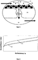
- FIG. 1 schematically shows such a wall flow filter substrate.
- the particle-containing exhaust gas flowing into the inflow channels (1) is forced to pass through the porous wall (4) through the gastight sealing plug (3) located on the outlet side and exits from the wall flow filter substrate from the outflow channels (2) closed on the inflow side out. This diesel soot is filtered out of the exhaust.
- the soot filtration in the wall flow filter substrate as it passes through the wall can be described as a two-step process.
- a first phase the so-called “depth filtration phase”
- soot particles stick in the pores of the wall as the particle-containing exhaust gas passes through the wall [ FIG. 2b ].
- filter cake formation [ Figure 2c ] in the entire inflow channel.
- the dynamic pressure above the wall flow filter substrate only increases linearly with the filtered amount of diesel soot.
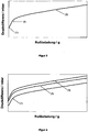
- FIG. 3 shows schematically the development of the dynamic pressure over the wall flow filter, starting from the soot-free filter as a function of the absorbed amount of soot. (1) shows the back pressure of the unfiltered filter, (2) the rise during the depth filtration phase, and (3) the linear back pressure increase during the filter cake formation phase.
- the above-described two-step process of soot filtration in the wall flow filter substrate is generally valid; he will be at non-coated Wall flow filter substrates are also observed, as with catalytically active wall flow filter substrates, with soot fire-wall coating, or with coatings having particular anchor structures to improve filtration efficiency.
- the output configuration of the wallflow filter primarily affects the output stall pressure of the component in an inaccessible condition, such as FIG. 4 can be seen.
- Catalytically coated wall flow filter substrates or those with a typical soot ignition coating (2) exhibit a significantly higher initial back pressure than uncoated wall flow filter substrates (1) in the unconscious state; the course of the dynamic pressure curve with increasing soot loading but is comparable to the course of the back pressure curve of the uncoated substrate (1).
- a substrate having a filtration efficiency enhancing coating (3) typically exhibits an inoperative initial stagnation pressure comparable to the initial stagnation pressure of catalytically coated wallflow filters.
- the increase in the back pressure during the depth filtration phase is significantly steeper, since the pore radius narrows even faster due to the deliberately installed anchor structures.
- a high dynamic pressure as well as a rapid increase in back pressure in diesel particulate filters used in motor vehicles is undesirable because, in use, it requires engine power to be expended to force exhaust gas through the exhaust gas purifier. This engine power is lost for driving the vehicle.
- optimum utilization of engine power for the drive is equivalent to an increase in effective fuel economy and fuel economy benefits, and thus also reduced CO 2 emissions of the vehicle.
- a catalyst loaded with a filter comprises a layer lying on the substrate walls, which has a pore diameter which is smaller than that of the substrate wall and the soot particles can intercept.
- the document DE 10 2006 040739 A1 describes filter substrates which are coated with a protective layer which prevents the penetration of particles.
- FIG. 6 shows schematically the effect achieved by the applied coating.
- the concept of backpressure reduction by applying a depth filtration reducing coating in the inflow channels can basically be applied to all wall flow filter substrates.
- Preferred embodiments of the components according to the invention comprise wall flow filter substrates which are made of silicon carbide, cordierite or aluminum titanate and which have pores in the walls between inlet and outlet channels with an average diameter of between 5 and 50 ⁇ m, particularly preferably between 10 and 25 ⁇ m.
- overcoat The coating according to the invention, the function of which is to significantly reduce the depth filtration, is referred to below as "overcoat”.
- Particulate filters produced according to the invention have an overcoat which contains a majority of one or more refractory oxides. So that the overcoat is such that the pores connecting the inflow and outflow ducts are closed for soot particles, without preventing the passage of the gaseous exhaust gas constituents, the materials used for the overcoat must be carefully selected. In particular, the oxides to be used must have a particle size distribution which is adapted to the pore size distribution in the wall of the substrate.
- the intended function of the overcoat is then fulfilled if the d 50 value of the particle size distribution of the oxides is equal to or greater than the d 5 value of the pore size distribution of the wall flow filter substrate, and at the same time the d 90 value of the particle size distribution of the oxides is equal to or greater than the d 95 .
- Value of the pore size distribution of the wall flow filter substrate is. (What is meant by the corresponding d x values of the particle size distribution on the one hand, and the pore size distribution on the other hand, has already been explained above.)
- the oxides have a d 50 value between 10 and 15 microns and a d 90 value, which is between 25 and 40 microns is. These are characterized not only by optimized functionality with regard to the reduction of the depth filtration but also by a particularly good adhesion to the wall flow filter substrate.
- the required particle size ranges can be well adjusted by targeted pre-milling of the oxide prior to introduction into the wall flow filter substrate.
- the oxides of the overcoate are preferably selected from the group consisting of alumina, rare earth-stabilized alumina, rare earth sesquioxide, titania, zirconia, cerium-zirconium mixed oxide, vanadium pentoxide, vanadium trioxide, tungsten trioxide , Molybdenum trioxide and mixtures thereof.
- Particularly preferred are oxides selected from the group consisting of alumina, rare earth stabilized alumina, rare earth sesquioxide, zirconia and mixtures thereof.
- Zeolite-based materials are generally not suitable as oxidic overcoat since the particle sizes of synthetic zeolites, usually with average particle sizes of d 50 ⁇ 3 ⁇ m, are significantly below the values required here.
- the overcoat is preferably applied with a layer thickness of 10 to 150 .mu.m, more preferably 20 to 100 .mu.m in the inflow channels of Wandtikfiltersubstrates.
- a layer thickness of 10 to 150 .mu.m more preferably 20 to 100 .mu.m in the inflow channels of Wandtikfiltersubstrates.
- corresponding layer thicknesses at a loading of 1 to 50 g / L solids, based on the volume of the wall flow filter substrate can be represented.
- Particularly preferred are loadings of 1 to 20 g / L solids, very particularly advantageous Layer thicknesses of 1 to 10 g / L solids, based on the volume of the wall flow filter substrate.
- a suitable oxide is selected and suspended in an amount of water that is at least twice the pore volume of the selected oxide. If appropriate, the resulting aqueous suspension of the oxide is ground with the aid of a Dyno mill until the required particle size distribution has been established.
- auxiliaries to increase the sedimentation stability of the suspension at this stage of the production process is harmless to the function of the overcoate to be produced, provided that these auxiliaries can be removed completely thermally during the calcination in the last preparation step.
- adhesion-promoting agents such as silica and other inorganic sols is harmless and may be advantageous in some embodiments.
- the suspension is pumped into the inflow channels of the wall flow filter substrate to be coated after any adjustment of the particle size distribution by grinding. After complete filling of the inflow channels with the suspension, the supernatant suspension is sucked out of the wall flow filter substrate again.
- the suction power is to be selected so that at the end of the process, the predetermined amount of solids remains in the inflow duct.
- the coated wall flow filter substrate thus produced is dried at 80 to 180 ° C in a hot air stream and then calcined at 250 to 600 ° C, preferably at 300 to 500 ° C. It is ready for use after calcination without further treatment.
- the concept of reducing the dynamic pressure by applying a deep-filtration-reducing coating (overlay) in the inflow channels can basically be applied to all wall-flow filter substrates.
- These include catalytically coated wall flow filter substrates or wall flow filter substrates with the soot ignition temperature lowering coatings.
- overcoats of refractory oxide material may be applied to wallflow filter substrates containing a catalytically active coating and / or a soot ignition temperature lowering coating predominantly present in the pores of the wall between the inlet and outlet channels.
- the layer thicknesses of which are preferred for optimum effectiveness of the oxide overcoating can lead to the initial stagnation pressure of the unimported part increasing more than would be achieved by reducing the depth of the back pressure by avoiding depth filtration.
- an additional catalytically active coating or / and an additional coating which lowers the soot ignition temperature to an inventive diesel particulate filter with overcoat.
- an embodiment basically has the disadvantage that the initial stagnation pressure of the unfiltered filter increases exorbitantly due to the superposed arrangement of two layers in the inflow channels. Therefore, such embodiments are only for special vehicle applications in question, in which the fuel consumption is irrelevant, but for the for example due to low average operating conditions of a soot ignition at very low temperatures and / or a high degree of continuous particulate trap regeneration (CRT ® effect) is required, such as for construction and other so-called "non-road” applications.
- CRT ® effect continuous particulate trap regeneration
- the oxides of the overcoate are preferably selected from the group consisting of alumina, rare earth stabilized alumina, rare earth metal sesquioxide, titania, zirconia, cerium-zirconium mixed oxide, vanadium pentoxide, vanadium trioxide, tungsten trioxide, molybdenum trioxide, and mixtures thereof ,
- These oxides often form the basis for the Rußzündtemperatur lowering coatings and / or for oxidation catalytic or reduction catalytic coatings that can be used to convert the pollutants contained in diesel exhaust except diesel soot carbon monoxide, residual hydrocarbons and nitrogen oxides into non-harmful components.
- additional catalytic activation of the depth filtration reducing coating can be achieved by admixture or impregnation of oxidation or reduction catalytic components and / or of components that can lower the soot ignition temperature.
- Example 1 (not according to the invention):
- a natural stone fiber material with a mean fiber length of 125 microns and an average mass-related diameter of the fibers of 9 microns was suspended in water.
- silica sol ST-OUP from Nissan Chemical
- the suspension was pumped through the wall flow filter substrate on the inflow channel, the amount of suspension pumped through the substrate being exactly the total amount of fiber material to be applied at 5 g / L , based on the component volume contained.
- the thus provided with a fiber mat component was dried at 120 ° C in a fan heater and then calcined in the fan heater for a period of one hour at 350 ° C.
- the filter so produced exhibited a significantly reduced back pressure rise due to depth filtration compared to the uncoated substrate, measured as a function of the amount of soot loaded.
- a precious metal-containing powder was first prepared as a catalytically active component of the coating.
- a ⁇ -alumina stabilized with 3% by weight of lanthanum sesquioxide was pore-filled with a mixture of an aqueous solution of a platinum precursor compound and an aqueous solution of a palladium precursor compound, whereby the total amount of the aqueous solution with which the ⁇ -alumina was treated, was chosen so that the flowability of the powder was maintained.
- the wet powder resulting from the impregnation was dried for 10 hours at 120 ° C and then calcined for four hours at 300 ° C.
- the finished noble metal-containing powder contained 11 wt .-% of precious metal, based on the total powder amount, with a platinum: palladium ratio of 2: 1.
- the thus obtained catalytically active component of the coating was suspended with stirring in an amount of water, which corresponded to about two and a half times the water absorption of the powder.
- the resulting suspension was milled with the aid of a Dyno mill until the particle size distribution showed a d 100 value smaller than 7 ⁇ m.
- the suspension was introduced into the walls of the abovementioned wall-flow filter substrates by pumping into the inflow channels and subsequent suction.
- the filters were then dried at 120 ° C in a fan heater and calcined for four hours at 300 ° C in a stationary oven.
- the applied amount of catalytically active coating in the finished diesel particulate filters was about 28 g / L, based on the volume of the component.
- one of the catalytically coated diesel particulate filters obtained in the comparative example was provided with an oxidic overcoat.
- FIG. 8 shows the particle size distribution of the final milled suspended oxide as measured by LS230 Particle Sizer from Beckman Coulter.
- the suspension was applied to one of the already catalytically coated diesel particle filters from the comparative example by pumping the coating suspension into the inflow channels and subsequent suction.
- the filter was then dried at 120 ° C in a fan heater and calcined for four hours at 350 ° C in a stationary oven.
- the load to be assigned to the overcoat in the finished diesel particulate filter was 5 g / L based on the volume of the component.
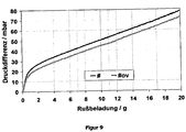
- the dynamic pressure behavior under soot loading was investigated comparatively on the catalytically coated diesel particle filter according to the prior art prepared in the comparative example and on the diesel particle filter according to the invention from example 2.
- the recording of the dynamic pressure curves during the loading of the filters with soot was carried out with the "Diesel Particulate Generator" DPG from Cambustion, whose measuring principle and methodology is familiar to the person skilled in the art, under the standard conditions recommended by the supplier of the device.
- FIG. 9 shows the result of the comparative study of the back pressure as a function of the amount of soot taken up.
- # designates the diesel particulate filter without overcoat from the comparative example, #ov the diesel particulate filter with overcoat from example 2.
- Both measured curves were corrected by subtracting the 1-axis reduced intercept value of the component # curve without overcoat to show the direct influence of the overcoat.
Landscapes
- Engineering & Computer Science (AREA)
- Chemical & Material Sciences (AREA)
- Ceramic Engineering (AREA)
- Organic Chemistry (AREA)
- Materials Engineering (AREA)
- Structural Engineering (AREA)
- Manufacturing & Machinery (AREA)
- Combustion & Propulsion (AREA)
- Mechanical Engineering (AREA)
- General Engineering & Computer Science (AREA)
- Filtering Materials (AREA)
- Processes For Solid Components From Exhaust (AREA)
- Exhaust Gas After Treatment (AREA)
- Catalysts (AREA)
- Nanotechnology (AREA)
Claims (7)
- Procédé de fabrication d'un filtre à particules diesel contenant un substrat de filtre à paroi filtrante à base de céramique et un revêtement en matériau à haut point de fusion appliqué dans les canaux d'admission, conçu de sorte qu'il ferme les pores, reliant les canaux d'admission et les canaux d'évacuation dans la paroi, côté admission pour les particules de suie, tout en permettant le passage des constituants gazeux des gaz d'échappement, le revêtement contenant majoritairement un ou plusieurs oxydes à haut point de fusion, dont les tailles des particules sont adaptées aux dimensions des pores dans la paroi du substrat de filtre à paroi filtrante, présentant les étapes de procédé suivantes :a. mise en suspension d'un oxyde dans une quantité d'eau qui est au moins deux fois supérieure au volume des pores de l'oxyde ;b. broyage de la suspension aqueuse obtenue dans l'étape a. jusqu'à ce que l'oxyde présente une distribution granulométrique des particules qui est adaptée à la distribution des dimensions des pores dans la paroi du substrat de filtre à paroi filtrante ;c. pompage de la suspension obtenue dans les canaux d'admission du substrat de filtre à paroi filtrante, jusqu'à ce que ceux-ci soient totalement remplis par la suspension ;d. extraction par aspiration de la suspension résiduelle hors du substrat de filtre à paroi filtrante, la puissance d'aspiration étant à choisir de sorte qu'à la fin du processus, une quantité de charge prédéfinie de solide reste dans le canal d'admission ;e. séchage du substrat de filtre à paroi filtrante résultant de l'étape d. dans un flux d'air chaud à 80 °C jusqu'à 180 °C ;f. calcination du substrat de filtre à paroi filtrante résultant de l'étape e. à 250 jusqu'à 600 °C, le broyage dans l'étape b. ayant lieu jusqu'à ce que la valeur d50 de la distribution granulométrique des particules de l'oxyde soit supérieure ou égale à la valeur d5 de la distribution des dimensions des pores du substrat de filtre à paroi filtrante, la valeur d90 de la distribution granulométrique des particules de l'oxyde étant simultanément identique ou supérieure à la valeur d95 de la distribution des dimensions des pores du substrat de filtre à paroi filtrante,la valeur d50 ou, selon le cas, la valeur d90 de la distribution granulométrique des particules de l'oxyde signifiant que 50 % ou, selon le cas, 90 % du volume total de l'oxyde ne contiennent que des particules dont le diamètre est inférieur ou égal à la valeur indiquée comme d50 ou, selon le cas, d90,
et la valeur d5 ou, selon le cas, la valeur d95 de la répartition des dimensions des pores du substrat de filtre à paroi filtrante signifiant que 5 % ou, selon le cas, 95 % du volume total des pores, pouvant être déterminé par porosimétrie au mercure, sont formés par des pores dont le diamètre est inférieur ou égal à la valeur indiquée respectivement comme d5 ou d95 et l'oxyde présentant, après le broyage, une distribution granulométrique présentant une valeur d50 entre 10 et 15 µm et une valeur d90 entre 25 et 40 µm. - Procédé selon la revendication 1,
caractérisé en ce que
l'oxyde est choisi dans le groupe constitué par l'oxyde d'aluminium, l'oxyde d'aluminium stabilisé par des terres rares, le sesquioxyde de métal des terres rares, le dioxyde de titane, l'oxyde de zirconium, l'oxyde mixte de cérium et zirconium, le pentoxyde de vanadium, le trioxyde de vanadium, le trioxyde de tungstène, le trioxyde de molybdène et leurs mélanges. - Procédé selon l'une quelconque des revendications 1 à 2,
caractérisé en ce que
le substrat de filtre à paroi filtrante est fabriqué à partir de carbure de silicium, de cordiérite ou de titanate d'aluminium et en ce que les parois présentent, entre les pores des canaux d'admission et d'évacuation, un diamètre moyen compris entre 5 µm et 50 µm. - Procédé selon la revendication 3,
caractérisé en ce que
le substrat de filtre à paroi filtrante contient un revêtement à action catalytique et/ou un revêtement faisant baisser la température d'allumage de la suie, qui est présent principalement dans les pores de la paroi entre les canaux d'admission et d'évacuation. - Procédé selon la revendication 1,
caractérisé en ce
des matières auxiliaires sont ajoutées à la suspension obtenue dans l'étape b. avant la réalisation de l'étape c. afin d'augmenter sa stabilité de sédimentation, dans lequel ces matières auxiliaires sont choisies de telle sorte qu'elles puissent être totalement éliminées par voie thermique lors de la calcination de l'étape f.. - Procédé selon la revendication 1,
caractérisé en ce que
des agents favorisant l'adhérence, tels que l'acide silicique et autres saumures inorganiques, sont ajoutés à la suspension obtenue dans l'étape b. avant la réalisation de l'étape c.. - Procédé selon la revendication 1,
caractérisé en ce que
l'épaisseur de couche du revêtement résultant de l'étape d. dans les canaux d'admission du substrat de filtre à paroi filtrante après traitement des étapes e. et f. est comprise entre 10 et 150 µm.
Priority Applications (3)
| Application Number | Priority Date | Filing Date | Title |
|---|---|---|---|
| EP15177154.0A EP2974779A1 (fr) | 2008-11-04 | 2008-11-04 | Filtre a particules diesel dote de proprietes de pression dynamique ameliorees |
| PL11000800T PL2319606T5 (pl) | 2008-11-04 | 2008-11-04 | Filtr drobin zawartych w spalinach silników wysokoprężnych ze zoptymalizowanymi właściwościami ciśnienia spiętrzania |
| EP11000800.0A EP2319606B2 (fr) | 2008-11-04 | 2008-11-04 | Filtre à particules diesel doté de propriétés de pression dynamique améliorées |
Applications Claiming Priority (2)
| Application Number | Priority Date | Filing Date | Title |
|---|---|---|---|
| EP08168287.4A EP2181749B2 (fr) | 2008-11-04 | 2008-11-04 | Filtre à particules diesel doté de propriétés de pression dynamique améliorées |
| EP11000800.0A EP2319606B2 (fr) | 2008-11-04 | 2008-11-04 | Filtre à particules diesel doté de propriétés de pression dynamique améliorées |
Related Parent Applications (3)
| Application Number | Title | Priority Date | Filing Date |
|---|---|---|---|
| EP08168287.4A Division EP2181749B2 (fr) | 2008-11-04 | 2008-11-04 | Filtre à particules diesel doté de propriétés de pression dynamique améliorées |
| EP08168287.4A Division-Into EP2181749B2 (fr) | 2008-11-04 | 2008-11-04 | Filtre à particules diesel doté de propriétés de pression dynamique améliorées |
| EP08168287.4 Division | 2008-11-04 |
Related Child Applications (2)
| Application Number | Title | Priority Date | Filing Date |
|---|---|---|---|
| EP15177154.0A Division-Into EP2974779A1 (fr) | 2008-11-04 | 2008-11-04 | Filtre a particules diesel dote de proprietes de pression dynamique ameliorees |
| EP15177154.0A Division EP2974779A1 (fr) | 2008-11-04 | 2008-11-04 | Filtre a particules diesel dote de proprietes de pression dynamique ameliorees |
Publications (3)
| Publication Number | Publication Date |
|---|---|
| EP2319606A1 EP2319606A1 (fr) | 2011-05-11 |
| EP2319606B1 EP2319606B1 (fr) | 2016-05-18 |
| EP2319606B2 true EP2319606B2 (fr) | 2019-08-07 |
Family
ID=40514051
Family Applications (3)
| Application Number | Title | Priority Date | Filing Date |
|---|---|---|---|
| EP15177154.0A Withdrawn EP2974779A1 (fr) | 2008-11-04 | 2008-11-04 | Filtre a particules diesel dote de proprietes de pression dynamique ameliorees |
| EP11000800.0A Active EP2319606B2 (fr) | 2008-11-04 | 2008-11-04 | Filtre à particules diesel doté de propriétés de pression dynamique améliorées |
| EP08168287.4A Active EP2181749B2 (fr) | 2008-11-04 | 2008-11-04 | Filtre à particules diesel doté de propriétés de pression dynamique améliorées |
Family Applications Before (1)
| Application Number | Title | Priority Date | Filing Date |
|---|---|---|---|
| EP15177154.0A Withdrawn EP2974779A1 (fr) | 2008-11-04 | 2008-11-04 | Filtre a particules diesel dote de proprietes de pression dynamique ameliorees |
Family Applications After (1)
| Application Number | Title | Priority Date | Filing Date |
|---|---|---|---|
| EP08168287.4A Active EP2181749B2 (fr) | 2008-11-04 | 2008-11-04 | Filtre à particules diesel doté de propriétés de pression dynamique améliorées |
Country Status (11)
| Country | Link |
|---|---|
| US (1) | US9051857B2 (fr) |
| EP (3) | EP2974779A1 (fr) |
| JP (1) | JP2012507402A (fr) |
| KR (1) | KR101643910B1 (fr) |
| CN (1) | CN102196853B (fr) |
| AT (1) | ATE503549T1 (fr) |
| BR (1) | BRPI0921618B1 (fr) |
| DE (1) | DE502008003033D1 (fr) |
| PL (1) | PL2319606T5 (fr) |
| RU (1) | RU2508154C2 (fr) |
| WO (1) | WO2010051877A1 (fr) |
Families Citing this family (25)
| Publication number | Priority date | Publication date | Assignee | Title |
|---|---|---|---|---|
| US8512657B2 (en) | 2009-02-26 | 2013-08-20 | Johnson Matthey Public Limited Company | Method and system using a filter for treating exhaust gas having particulate matter |
| GB0903262D0 (en) | 2009-02-26 | 2009-04-08 | Johnson Matthey Plc | Filter |
| PL2558691T3 (pl) * | 2010-04-14 | 2017-01-31 | Umicore Ag & Co. Kg | Filtr cząstek stałych z powłoką redukcyjno-katalityczną o polepszonych właściwościach |
| EP2772302A1 (fr) | 2013-02-27 | 2014-09-03 | Umicore AG & Co. KG | Catalyseur d'oxydation hexagonale |
| CN104043330B (zh) | 2013-03-15 | 2017-03-01 | 通用电气公司 | 氧化含碳物质的方法、柴油颗粒捕集器和排气装置 |
| CN103422947B (zh) * | 2013-05-31 | 2015-09-02 | 徐义联 | 一种汽车尾气净化装置 |
| JP2016530070A (ja) * | 2013-05-31 | 2016-09-29 | ジョンソン、マッセイ、パブリック、リミテッド、カンパニーJohnson Matthey Public Limited Company | 排ガスを処理するための触媒化フィルタ |
| DE102013013973A1 (de) | 2013-08-23 | 2015-02-26 | Clariant Produkte (Deutschland) Gmbh | Partikelfilter zur Reinigung von Abgasen, Abgasreinigungssystem und Verfahren zur Reinigung von Abgas |
| IN2014MN01020A (fr) * | 2014-01-17 | 2015-09-11 | Vida Holdings Corp Ltd | |
| CN107690352B9 (zh) | 2015-03-30 | 2021-06-11 | 巴斯夫公司 | 用于柴油发动机排放控制的多功能过滤器 |
| JP6654085B2 (ja) * | 2016-03-31 | 2020-02-26 | 日本碍子株式会社 | 多孔質材料、及び多孔質材料の製造方法並びにハニカム構造体 |
| EP3281699A1 (fr) * | 2016-08-11 | 2018-02-14 | Umicore AG & Co. KG | Filtre à particules avec catalyseur de réduction catalytique sélective |
| US10933373B2 (en) | 2017-03-23 | 2021-03-02 | Umicore Ag & Co. Kg | Catalytically active particulate filter |
| EP3501647A1 (fr) | 2017-12-19 | 2019-06-26 | Umicore Ag & Co. Kg | Filtre à particules catalityquement actif |
| EP3501648B1 (fr) | 2017-12-19 | 2023-10-04 | Umicore Ag & Co. Kg | Filtre à particules catalityquement actif |
| EP3501646A1 (fr) | 2017-12-19 | 2019-06-26 | Umicore Ag & Co. Kg | Filtre à particules catalityquement actif |
| DE102018110804B4 (de) * | 2018-05-04 | 2024-06-27 | Umicore Ag & Co. Kg | Beschichteter Wandflussfilter |
| CN108503367B (zh) * | 2018-06-29 | 2019-04-02 | 南通志乐新材料有限公司 | 一种高温烟气除尘用复合型陶瓷过滤材料 |
| DE102019200180A1 (de) * | 2018-07-25 | 2020-01-30 | Audi Ag | Filterelement für einen Partikelfilter, Abgaspartikelfilter, Verfahren zum Herstellen eines Filterelements sowie Verwendung eines Beschichtungsmaterials |
| DE102018127955A1 (de) * | 2018-11-08 | 2020-05-14 | Umicore Ag & Co. Kg | Katalytisch aktiver Partikelfilter mit hoher Filtrationseffizienz |
| KR20220095236A (ko) * | 2019-11-12 | 2022-07-06 | 바스프 코포레이션 | 미립자 필터 |
| EP4255605A1 (fr) * | 2020-12-04 | 2023-10-11 | BASF Corporation | Filtre à particules ayant une couche de matériau fonctionnel à distribution centralisée et son processus de préparation |
| CN112958067A (zh) * | 2021-02-06 | 2021-06-15 | 昆明贵研催化剂有限责任公司 | 一种汽油车颗粒捕集催化剂及其制备方法 |
| CN113277873A (zh) * | 2021-05-18 | 2021-08-20 | 山东大学 | 一种矿渣纤维基多孔过滤陶瓷的制备方法 |
| JP7144105B1 (ja) * | 2022-03-03 | 2022-09-29 | 浅田化学工業株式会社 | 中空多孔質アルミナ粒子の製造方法 |
Citations (2)
| Publication number | Priority date | Publication date | Assignee | Title |
|---|---|---|---|---|
| US4749671A (en) † | 1985-07-02 | 1988-06-07 | Nippon Shokubai Kagaku Kogyo Co., Ltd. | Exhaust gas cleaning catalyst and process for production thereof |
| JP2007144371A (ja) † | 2005-11-30 | 2007-06-14 | Toyota Motor Corp | 排ガス浄化用触媒及びその製造方法 |
Family Cites Families (36)
| Publication number | Priority date | Publication date | Assignee | Title |
|---|---|---|---|---|
| DE2951316A1 (de) * | 1979-12-20 | 1981-07-02 | Degussa Ag, 6000 Frankfurt | Katalytisches filter fuer die dieselabgasreinigung |
| JPH0633734A (ja) * | 1992-07-10 | 1994-02-08 | Ibiden Co Ltd | 排気ガス浄化装置 |
| RU2059841C1 (ru) * | 1993-08-24 | 1996-05-10 | Малое предприятие "Технология" | Фильтр для очистки выхлопных газов двигателей внутреннего сгорания |
| RU2094623C1 (ru) * | 1995-05-26 | 1997-10-27 | Иван Иванович Кутыш | Фильтрующий элемент с петлевым движением отработавших газов |
| JPH09173866A (ja) † | 1995-12-28 | 1997-07-08 | Nippon Soken Inc | ディーゼル排ガス浄化フィルタ |
| JPH09217618A (ja) | 1996-02-09 | 1997-08-19 | Isuzu Ceramics Kenkyusho:Kk | 排気ガス浄化装置 |
| GB9802504D0 (en) | 1998-02-06 | 1998-04-01 | Johnson Matthey Plc | Improvements in emission control |
| WO2002026379A1 (fr) * | 2000-09-29 | 2002-04-04 | Omg Ag & Co. Kg | Filtre catalytique de particules de suie et utilisation de celui-ci afin de traiter des gaz d'echappement pauvres |
| JP2002320807A (ja) * | 2001-04-27 | 2002-11-05 | Mitsui Eng & Shipbuild Co Ltd | ハニカムフィルタ及びその製造方法 |
| JP4174976B2 (ja) * | 2001-06-01 | 2008-11-05 | 日産自動車株式会社 | 排気浄化装置及びその製造方法 |
| JP3997825B2 (ja) * | 2001-06-28 | 2007-10-24 | 株式会社デンソー | セラミックフィルタおよび触媒付セラミックフィルタ |
| EP1458960B1 (fr) | 2001-12-20 | 2011-02-09 | Johnson Matthey Public Limited Company | Ameliorations dans la reduction catalytique selective |
| DE10216070C1 (de) | 2002-04-11 | 2003-04-24 | Hts Hoch Technologie Systeme G | Fahrzeugkindersitz mit ISOFIX-Befestigungssystem |
| DE10238770A1 (de) | 2002-08-23 | 2004-03-11 | Umicore Ag & Co.Kg | Vorrichtung zur Entfernung von Rußpartikeln aus dem Abgas eines Dieselmotors |
| US7332135B2 (en) | 2002-10-22 | 2008-02-19 | Ford Global Technologies, Llc | Catalyst system for the reduction of NOx and NH3 emissions |
| US6946013B2 (en) * | 2002-10-28 | 2005-09-20 | Geo2 Technologies, Inc. | Ceramic exhaust filter |
| JP4284588B2 (ja) | 2003-01-10 | 2009-06-24 | トヨタ自動車株式会社 | 排ガス浄化フィルタ触媒 |
| DE10323607B4 (de) | 2003-05-20 | 2019-05-09 | Robert Bosch Gmbh | Vorrichtung zur Reinigung von Abgasen eines Verbrennungsmotors |
| DE10335785A1 (de) | 2003-08-05 | 2005-03-10 | Umicore Ag & Co Kg | Katalysatoranordnung und Verfahren zur Reinigung des Abgases von mager betriebenen Verbrennungsmotoren |
| US7229597B2 (en) | 2003-08-05 | 2007-06-12 | Basfd Catalysts Llc | Catalyzed SCR filter and emission treatment system |
| JP4815108B2 (ja) | 2003-12-26 | 2011-11-16 | イビデン株式会社 | ハニカム構造体 |
| JP2008501496A (ja) | 2004-06-05 | 2008-01-24 | ユミコア・アクチエンゲゼルシャフト・ウント・コムパニー・コマンディットゲゼルシャフト | 触媒コーティングを備えた粒子フィルター |
| JP2006007117A (ja) * | 2004-06-25 | 2006-01-12 | Ne Chemcat Corp | 排気ガス浄化構造体および該構造体を用いた排気ガス浄化方法 |
| DE102004040551A1 (de) | 2004-08-21 | 2006-02-23 | Umicore Ag & Co. Kg | Verfahren zur Beschichtung eines Wandflußfilters mit einer Beschichtungszusammensetzung |
| JPWO2006035823A1 (ja) * | 2004-09-30 | 2008-05-15 | イビデン株式会社 | ハニカム構造体 |
| DE102004051099A1 (de) | 2004-10-19 | 2006-04-20 | Umicore Ag & Co. Kg | Verfahren und Vorrichtung zum Beschichten einer Serie von Tragkörpern |
| JP2007285295A (ja) | 2006-03-24 | 2007-11-01 | Ngk Insulators Ltd | 排気ガス浄化システム |
| JP2007296512A (ja) * | 2006-04-05 | 2007-11-15 | Ngk Insulators Ltd | ハニカムフィルタ |
| EP2038236B1 (fr) | 2006-06-30 | 2013-08-14 | Corning Incorporated | Structures poreuses en nid d'abeilles en céramique à faible fissuration |
| DE102006040739A1 (de) * | 2006-08-31 | 2008-03-06 | Robert Bosch Gmbh | Filter zur Entfernung von Partikeln aus einem Gasstrom sowie Verfahren zu seiner Herstellung |
| DE502007003465D1 (de) | 2007-02-23 | 2010-05-27 | Umicore Ag & Co Kg | Katalytisch aktiviertes Dieselpartikelfilter mit Ammoniak-Sperrwirkung |
| JP5616059B2 (ja) | 2007-04-27 | 2014-10-29 | 日本碍子株式会社 | ハニカムフィルタ |
| DE102007021468A1 (de) * | 2007-05-08 | 2008-11-13 | Robert Bosch Gmbh | Verfahren zur Herstellung eines Filters sowie Filter |
| JP5770409B2 (ja) | 2007-11-01 | 2015-08-26 | 日野自動車株式会社 | 排ガス浄化装置 |
| JP5208886B2 (ja) * | 2008-09-03 | 2013-06-12 | 日本碍子株式会社 | 触媒担持フィルタ |
| PL2558691T3 (pl) | 2010-04-14 | 2017-01-31 | Umicore Ag & Co. Kg | Filtr cząstek stałych z powłoką redukcyjno-katalityczną o polepszonych właściwościach |
-
2008
- 2008-11-04 EP EP15177154.0A patent/EP2974779A1/fr not_active Withdrawn
- 2008-11-04 EP EP11000800.0A patent/EP2319606B2/fr active Active
- 2008-11-04 EP EP08168287.4A patent/EP2181749B2/fr active Active
- 2008-11-04 AT AT08168287T patent/ATE503549T1/de active
- 2008-11-04 PL PL11000800T patent/PL2319606T5/pl unknown
- 2008-11-04 DE DE502008003033T patent/DE502008003033D1/de active Active
-
2009
- 2009-09-11 US US13/127,326 patent/US9051857B2/en active Active
- 2009-09-11 JP JP2011535016A patent/JP2012507402A/ja active Pending
- 2009-09-11 KR KR1020117012553A patent/KR101643910B1/ko active IP Right Grant
- 2009-09-11 RU RU2011122210/05A patent/RU2508154C2/ru active
- 2009-09-11 WO PCT/EP2009/006618 patent/WO2010051877A1/fr active Application Filing
- 2009-09-11 CN CN200980142826.9A patent/CN102196853B/zh active Active
- 2009-09-11 BR BRPI0921618-9A patent/BRPI0921618B1/pt active IP Right Grant
Patent Citations (2)
| Publication number | Priority date | Publication date | Assignee | Title |
|---|---|---|---|---|
| US4749671A (en) † | 1985-07-02 | 1988-06-07 | Nippon Shokubai Kagaku Kogyo Co., Ltd. | Exhaust gas cleaning catalyst and process for production thereof |
| JP2007144371A (ja) † | 2005-11-30 | 2007-06-14 | Toyota Motor Corp | 排ガス浄化用触媒及びその製造方法 |
Also Published As
| Publication number | Publication date |
|---|---|
| CN102196853A (zh) | 2011-09-21 |
| PL2319606T3 (pl) | 2017-09-29 |
| WO2010051877A1 (fr) | 2010-05-14 |
| RU2508154C2 (ru) | 2014-02-27 |
| EP2181749B2 (fr) | 2018-10-03 |
| BRPI0921618A2 (pt) | 2018-10-09 |
| EP2974779A1 (fr) | 2016-01-20 |
| ATE503549T1 (de) | 2011-04-15 |
| KR101643910B1 (ko) | 2016-07-29 |
| EP2319606B1 (fr) | 2016-05-18 |
| JP2012507402A (ja) | 2012-03-29 |
| DE502008003033D1 (de) | 2011-05-12 |
| RU2011122210A (ru) | 2012-12-27 |
| EP2181749B1 (fr) | 2011-03-30 |
| CN102196853B (zh) | 2014-01-08 |
| EP2319606A1 (fr) | 2011-05-11 |
| EP2181749A1 (fr) | 2010-05-05 |
| US9051857B2 (en) | 2015-06-09 |
| KR20110091736A (ko) | 2011-08-12 |
| US20120014842A1 (en) | 2012-01-19 |
| PL2319606T5 (pl) | 2020-01-31 |
| BRPI0921618B1 (pt) | 2020-08-25 |
Similar Documents
| Publication | Publication Date | Title |
|---|---|---|
| EP2319606B2 (fr) | Filtre à particules diesel doté de propriétés de pression dynamique améliorées | |
| EP2558691B1 (fr) | Filtre à particules diesel revêtu d'un réducteur catalytique ayant des propriétés améliorées | |
| EP2247385B1 (fr) | Procédé d'application d'un revêtement sur un filtre à particules diesel et filtre à particules diesel fabriqué par ce procédé | |
| EP1965917B1 (fr) | Procede de revetement catalytique de corps alveolaires ceramiques | |
| EP3877633A1 (fr) | Filtre à particules catalytiquement actif ayant une efficacité de filtration élevée | |
| DE102004040549A1 (de) | Katalytisch beschichtetes Partikelfilter und Verfahren zu seiner Herstellung sowie seine Verwendung | |
| DE102012220181A1 (de) | Partikelfilter | |
| DE102018110804A1 (de) | Beschichteter Wandflussfilter | |
| EP4015067A1 (fr) | Filtre à particules catalytiquement actif à efficacité de filtration élevée | |
| EP2059660A1 (fr) | Filtre destiné à éliminer des particules d'un flux gazeux et procédé de fabrication associé | |
| WO2022129010A1 (fr) | Filtre à particules catalytiquement actif à haut degré d'efficacité de filtration | |
| DE102006027578A1 (de) | Filter zur Reinigung von Gasgemischen sowie Verfahren zu dessen Herstellung | |
| WO2022129023A1 (fr) | Filtre à particules catalytiquement actif ayant un haut degré d'efficacité de filtration | |
| WO2022129014A1 (fr) | Filtre à particules catalytiquement actif ayant un haut degré d'efficacité de filtration | |
| EP3946691A1 (fr) | Filtre à particules à activité catalytique | |
| DE102007039249A1 (de) | Verfahren zur Herstellung eines keramischen Trägers sowie Filter | |
| DE102007039248A1 (de) | Verfahren zur Herstellung eines katalytisch aktiven, keramischen Trägers sowie Filter | |
| DE102021107130B4 (de) | Vorrichtung zur Erhöhung der Frischfiltration von Benzinpartikelfiltern | |
| WO2024028197A1 (fr) | Filtre à particules catalytiquement actif ayant un degré élevé d'efficacité de filtration et une fonction d'oxydation | |
| WO2007141072A1 (fr) | Filtre pour enlever des particules d'un flux de gaz ainsi que son procédé de fabrication |
Legal Events
| Date | Code | Title | Description |
|---|---|---|---|
| PUAI | Public reference made under article 153(3) epc to a published international application that has entered the european phase |
Free format text: ORIGINAL CODE: 0009012 |
|
| 17P | Request for examination filed |
Effective date: 20110202 |
|
| AC | Divisional application: reference to earlier application |
Ref document number: 2181749 Country of ref document: EP Kind code of ref document: P |
|
| AK | Designated contracting states |
Kind code of ref document: A1 Designated state(s): AT BE BG CH CY CZ DE DK EE ES FI FR GB GR HR HU IE IS IT LI LT LU LV MC MT NL NO PL PT RO SE SI SK TR |
|
| 17Q | First examination report despatched |
Effective date: 20140310 |
|
| REG | Reference to a national code |
Ref country code: DE Ref legal event code: R079 Ref document number: 502008014232 Country of ref document: DE Free format text: PREVIOUS MAIN CLASS: B01D0046240000 Ipc: C04B0035195000 |
|
| GRAP | Despatch of communication of intention to grant a patent |
Free format text: ORIGINAL CODE: EPIDOSNIGR1 |
|
| RIC1 | Information provided on ipc code assigned before grant |
Ipc: C04B 35/565 20060101ALI20160211BHEP Ipc: C04B 38/00 20060101ALI20160211BHEP Ipc: C04B 111/00 20060101ALI20160211BHEP Ipc: C04B 35/478 20060101ALI20160211BHEP Ipc: C04B 35/195 20060101AFI20160211BHEP Ipc: F01N 3/022 20060101ALI20160211BHEP |
|
| INTG | Intention to grant announced |
Effective date: 20160310 |
|
| GRAS | Grant fee paid |
Free format text: ORIGINAL CODE: EPIDOSNIGR3 |
|
| GRAA | (expected) grant |
Free format text: ORIGINAL CODE: 0009210 |
|
| AC | Divisional application: reference to earlier application |
Ref document number: 2181749 Country of ref document: EP Kind code of ref document: P |
|
| AK | Designated contracting states |
Kind code of ref document: B1 Designated state(s): AT BE BG CH CY CZ DE DK EE ES FI FR GB GR HR HU IE IS IT LI LT LU LV MC MT NL NO PL PT RO SE SI SK TR |
|
| REG | Reference to a national code |
Ref country code: GB Ref legal event code: FG4D Free format text: NOT ENGLISH |
|
| RIN1 | Information on inventor provided before grant (corrected) |
Inventor name: JESKE, GERALD, DR. Inventor name: FRANTZ, STEPHANIE DR. Inventor name: DORNHAUS, FRANZ, DR. |
|
| REG | Reference to a national code |
Ref country code: CH Ref legal event code: EP |
|
| REG | Reference to a national code |
Ref country code: IE Ref legal event code: FG4D Free format text: LANGUAGE OF EP DOCUMENT: GERMAN Ref country code: AT Ref legal event code: REF Ref document number: 800304 Country of ref document: AT Kind code of ref document: T Effective date: 20160615 |
|
| REG | Reference to a national code |
Ref country code: DE Ref legal event code: R096 Ref document number: 502008014232 Country of ref document: DE |
|
| REG | Reference to a national code |
Ref country code: NL Ref legal event code: MP Effective date: 20160518 |
|
| REG | Reference to a national code |
Ref country code: LT Ref legal event code: MG4D |
|
| REG | Reference to a national code |
Ref country code: FR Ref legal event code: PLFP Year of fee payment: 9 |
|
| PG25 | Lapsed in a contracting state [announced via postgrant information from national office to epo] |
Ref country code: LT Free format text: LAPSE BECAUSE OF FAILURE TO SUBMIT A TRANSLATION OF THE DESCRIPTION OR TO PAY THE FEE WITHIN THE PRESCRIBED TIME-LIMIT Effective date: 20160518 Ref country code: NO Free format text: LAPSE BECAUSE OF FAILURE TO SUBMIT A TRANSLATION OF THE DESCRIPTION OR TO PAY THE FEE WITHIN THE PRESCRIBED TIME-LIMIT Effective date: 20160818 Ref country code: NL Free format text: LAPSE BECAUSE OF FAILURE TO SUBMIT A TRANSLATION OF THE DESCRIPTION OR TO PAY THE FEE WITHIN THE PRESCRIBED TIME-LIMIT Effective date: 20160518 Ref country code: FI Free format text: LAPSE BECAUSE OF FAILURE TO SUBMIT A TRANSLATION OF THE DESCRIPTION OR TO PAY THE FEE WITHIN THE PRESCRIBED TIME-LIMIT Effective date: 20160518 |
|
| PG25 | Lapsed in a contracting state [announced via postgrant information from national office to epo] |
Ref country code: ES Free format text: LAPSE BECAUSE OF FAILURE TO SUBMIT A TRANSLATION OF THE DESCRIPTION OR TO PAY THE FEE WITHIN THE PRESCRIBED TIME-LIMIT Effective date: 20160518 Ref country code: HR Free format text: LAPSE BECAUSE OF FAILURE TO SUBMIT A TRANSLATION OF THE DESCRIPTION OR TO PAY THE FEE WITHIN THE PRESCRIBED TIME-LIMIT Effective date: 20160518 Ref country code: GR Free format text: LAPSE BECAUSE OF FAILURE TO SUBMIT A TRANSLATION OF THE DESCRIPTION OR TO PAY THE FEE WITHIN THE PRESCRIBED TIME-LIMIT Effective date: 20160819 Ref country code: PT Free format text: LAPSE BECAUSE OF FAILURE TO SUBMIT A TRANSLATION OF THE DESCRIPTION OR TO PAY THE FEE WITHIN THE PRESCRIBED TIME-LIMIT Effective date: 20160919 Ref country code: SE Free format text: LAPSE BECAUSE OF FAILURE TO SUBMIT A TRANSLATION OF THE DESCRIPTION OR TO PAY THE FEE WITHIN THE PRESCRIBED TIME-LIMIT Effective date: 20160518 Ref country code: LV Free format text: LAPSE BECAUSE OF FAILURE TO SUBMIT A TRANSLATION OF THE DESCRIPTION OR TO PAY THE FEE WITHIN THE PRESCRIBED TIME-LIMIT Effective date: 20160518 |
|
| PG25 | Lapsed in a contracting state [announced via postgrant information from national office to epo] |
Ref country code: SK Free format text: LAPSE BECAUSE OF FAILURE TO SUBMIT A TRANSLATION OF THE DESCRIPTION OR TO PAY THE FEE WITHIN THE PRESCRIBED TIME-LIMIT Effective date: 20160518 Ref country code: RO Free format text: LAPSE BECAUSE OF FAILURE TO SUBMIT A TRANSLATION OF THE DESCRIPTION OR TO PAY THE FEE WITHIN THE PRESCRIBED TIME-LIMIT Effective date: 20160518 Ref country code: CZ Free format text: LAPSE BECAUSE OF FAILURE TO SUBMIT A TRANSLATION OF THE DESCRIPTION OR TO PAY THE FEE WITHIN THE PRESCRIBED TIME-LIMIT Effective date: 20160518 Ref country code: DK Free format text: LAPSE BECAUSE OF FAILURE TO SUBMIT A TRANSLATION OF THE DESCRIPTION OR TO PAY THE FEE WITHIN THE PRESCRIBED TIME-LIMIT Effective date: 20160518 Ref country code: EE Free format text: LAPSE BECAUSE OF FAILURE TO SUBMIT A TRANSLATION OF THE DESCRIPTION OR TO PAY THE FEE WITHIN THE PRESCRIBED TIME-LIMIT Effective date: 20160518 |
|
| REG | Reference to a national code |
Ref country code: DE Ref legal event code: R026 Ref document number: 502008014232 Country of ref document: DE |
|
| PG25 | Lapsed in a contracting state [announced via postgrant information from national office to epo] |
Ref country code: BE Free format text: LAPSE BECAUSE OF NON-PAYMENT OF DUE FEES Effective date: 20161130 |
|
| PLBI | Opposition filed |
Free format text: ORIGINAL CODE: 0009260 |
|
| PLAX | Notice of opposition and request to file observation + time limit sent |
Free format text: ORIGINAL CODE: EPIDOSNOBS2 |
|
| 26 | Opposition filed |
Opponent name: JOHNSON MATTHEY PUBLIC LIMITED COMPANY Effective date: 20170218 |
|
| PG25 | Lapsed in a contracting state [announced via postgrant information from national office to epo] |
Ref country code: SI Free format text: LAPSE BECAUSE OF FAILURE TO SUBMIT A TRANSLATION OF THE DESCRIPTION OR TO PAY THE FEE WITHIN THE PRESCRIBED TIME-LIMIT Effective date: 20160518 |
|
| REG | Reference to a national code |
Ref country code: CH Ref legal event code: PL |
|
| PG25 | Lapsed in a contracting state [announced via postgrant information from national office to epo] |
Ref country code: LI Free format text: LAPSE BECAUSE OF NON-PAYMENT OF DUE FEES Effective date: 20161130 Ref country code: CH Free format text: LAPSE BECAUSE OF NON-PAYMENT OF DUE FEES Effective date: 20161130 |
|
| PLBB | Reply of patent proprietor to notice(s) of opposition received |
Free format text: ORIGINAL CODE: EPIDOSNOBS3 |
|
| REG | Reference to a national code |
Ref country code: IE Ref legal event code: MM4A |
|
| REG | Reference to a national code |
Ref country code: FR Ref legal event code: PLFP Year of fee payment: 10 |
|
| PG25 | Lapsed in a contracting state [announced via postgrant information from national office to epo] |
Ref country code: LU Free format text: LAPSE BECAUSE OF NON-PAYMENT OF DUE FEES Effective date: 20161130 |
|
| PG25 | Lapsed in a contracting state [announced via postgrant information from national office to epo] |
Ref country code: IE Free format text: LAPSE BECAUSE OF NON-PAYMENT OF DUE FEES Effective date: 20161104 |
|
| REG | Reference to a national code |
Ref country code: AT Ref legal event code: MM01 Ref document number: 800304 Country of ref document: AT Kind code of ref document: T Effective date: 20161104 |
|
| PG25 | Lapsed in a contracting state [announced via postgrant information from national office to epo] |
Ref country code: AT Free format text: LAPSE BECAUSE OF NON-PAYMENT OF DUE FEES Effective date: 20161104 |
|
| REG | Reference to a national code |
Ref country code: BE Ref legal event code: MM Effective date: 20161130 |
|
| PG25 | Lapsed in a contracting state [announced via postgrant information from national office to epo] |
Ref country code: HU Free format text: LAPSE BECAUSE OF FAILURE TO SUBMIT A TRANSLATION OF THE DESCRIPTION OR TO PAY THE FEE WITHIN THE PRESCRIBED TIME-LIMIT; INVALID AB INITIO Effective date: 20081104 Ref country code: CY Free format text: LAPSE BECAUSE OF FAILURE TO SUBMIT A TRANSLATION OF THE DESCRIPTION OR TO PAY THE FEE WITHIN THE PRESCRIBED TIME-LIMIT Effective date: 20160518 |
|
| PG25 | Lapsed in a contracting state [announced via postgrant information from national office to epo] |
Ref country code: MC Free format text: LAPSE BECAUSE OF FAILURE TO SUBMIT A TRANSLATION OF THE DESCRIPTION OR TO PAY THE FEE WITHIN THE PRESCRIBED TIME-LIMIT Effective date: 20160518 Ref country code: TR Free format text: LAPSE BECAUSE OF FAILURE TO SUBMIT A TRANSLATION OF THE DESCRIPTION OR TO PAY THE FEE WITHIN THE PRESCRIBED TIME-LIMIT Effective date: 20160518 Ref country code: IS Free format text: LAPSE BECAUSE OF FAILURE TO SUBMIT A TRANSLATION OF THE DESCRIPTION OR TO PAY THE FEE WITHIN THE PRESCRIBED TIME-LIMIT Effective date: 20160518 |
|
| PG25 | Lapsed in a contracting state [announced via postgrant information from national office to epo] |
Ref country code: BG Free format text: LAPSE BECAUSE OF FAILURE TO SUBMIT A TRANSLATION OF THE DESCRIPTION OR TO PAY THE FEE WITHIN THE PRESCRIBED TIME-LIMIT Effective date: 20160518 |
|
| REG | Reference to a national code |
Ref country code: FR Ref legal event code: PLFP Year of fee payment: 11 |
|
| PG25 | Lapsed in a contracting state [announced via postgrant information from national office to epo] |
Ref country code: MT Free format text: LAPSE BECAUSE OF FAILURE TO SUBMIT A TRANSLATION OF THE DESCRIPTION OR TO PAY THE FEE WITHIN THE PRESCRIBED TIME-LIMIT Effective date: 20160518 |
|
| PLAB | Opposition data, opponent's data or that of the opponent's representative modified |
Free format text: ORIGINAL CODE: 0009299OPPO |
|
| R26 | Opposition filed (corrected) |
Opponent name: JOHNSON MATTHEY PUBLIC LIMITED COMPANY Effective date: 20170218 |
|
| PUAH | Patent maintained in amended form |
Free format text: ORIGINAL CODE: 0009272 |
|
| STAA | Information on the status of an ep patent application or granted ep patent |
Free format text: STATUS: PATENT MAINTAINED AS AMENDED |
|
| 27A | Patent maintained in amended form |
Effective date: 20190807 |
|
| AK | Designated contracting states |
Kind code of ref document: B2 Designated state(s): AT BE BG CH CY CZ DE DK EE ES FI FR GB GR HR HU IE IS IT LI LT LU LV MC MT NL NO PL PT RO SE SI SK TR |
|
| REG | Reference to a national code |
Ref country code: DE Ref legal event code: R102 Ref document number: 502008014232 Country of ref document: DE |
|
| REG | Reference to a national code |
Ref country code: DE Ref legal event code: R084 Ref document number: 502008014232 Country of ref document: DE |
|
| P01 | Opt-out of the competence of the unified patent court (upc) registered |
Effective date: 20230602 |
|
| PGFP | Annual fee paid to national office [announced via postgrant information from national office to epo] |
Ref country code: GB Payment date: 20230914 Year of fee payment: 16 |
|
| PGFP | Annual fee paid to national office [announced via postgrant information from national office to epo] |
Ref country code: PL Payment date: 20230911 Year of fee payment: 16 Ref country code: FR Payment date: 20230911 Year of fee payment: 16 |
|
| PGFP | Annual fee paid to national office [announced via postgrant information from national office to epo] |
Ref country code: IT Payment date: 20231010 Year of fee payment: 16 Ref country code: DE Payment date: 20230912 Year of fee payment: 16 |