EP2318229B1 - Réaction d'accélérateur pour appareil de commande - Google Patents
Réaction d'accélérateur pour appareil de commande Download PDFInfo
- Publication number
- EP2318229B1 EP2318229B1 EP09802585.1A EP09802585A EP2318229B1 EP 2318229 B1 EP2318229 B1 EP 2318229B1 EP 09802585 A EP09802585 A EP 09802585A EP 2318229 B1 EP2318229 B1 EP 2318229B1
- Authority
- EP
- European Patent Office
- Prior art keywords
- accelerator
- vehicle
- threshold value
- opening
- degree
- Prior art date
- Legal status (The legal status is an assumption and is not a legal conclusion. Google has not performed a legal analysis and makes no representation as to the accuracy of the status listed.)
- Active
Links
- 238000006243 chemical reaction Methods 0.000 title claims description 90
- 230000001133 acceleration Effects 0.000 claims description 18
- 238000000034 method Methods 0.000 claims description 17
- 230000007423 decrease Effects 0.000 claims description 7
- 230000005540 biological transmission Effects 0.000 description 33
- 239000000446 fuel Substances 0.000 description 23
- 239000003570 air Substances 0.000 description 22
- 238000012937 correction Methods 0.000 description 21
- 230000000994 depressogenic effect Effects 0.000 description 10
- 238000010586 diagram Methods 0.000 description 10
- 238000002485 combustion reaction Methods 0.000 description 7
- 230000000881 depressing effect Effects 0.000 description 5
- 238000001514 detection method Methods 0.000 description 5
- 230000035807 sensation Effects 0.000 description 5
- 239000012080 ambient air Substances 0.000 description 2
- 230000001174 ascending effect Effects 0.000 description 2
- 238000005096 rolling process Methods 0.000 description 2
- 230000001276 controlling effect Effects 0.000 description 1
- 238000002347 injection Methods 0.000 description 1
- 239000007924 injection Substances 0.000 description 1
- 230000001105 regulatory effect Effects 0.000 description 1
Images


Classifications
-
- B—PERFORMING OPERATIONS; TRANSPORTING
- B60—VEHICLES IN GENERAL
- B60K—ARRANGEMENT OR MOUNTING OF PROPULSION UNITS OR OF TRANSMISSIONS IN VEHICLES; ARRANGEMENT OR MOUNTING OF PLURAL DIVERSE PRIME-MOVERS IN VEHICLES; AUXILIARY DRIVES FOR VEHICLES; INSTRUMENTATION OR DASHBOARDS FOR VEHICLES; ARRANGEMENTS IN CONNECTION WITH COOLING, AIR INTAKE, GAS EXHAUST OR FUEL SUPPLY OF PROPULSION UNITS IN VEHICLES
- B60K26/00—Arrangements or mounting of propulsion unit control devices in vehicles
- B60K26/02—Arrangements or mounting of propulsion unit control devices in vehicles of initiating means or elements
- B60K26/021—Arrangements or mounting of propulsion unit control devices in vehicles of initiating means or elements with means for providing feel, e.g. by changing pedal force characteristics
-
- F—MECHANICAL ENGINEERING; LIGHTING; HEATING; WEAPONS; BLASTING
- F02—COMBUSTION ENGINES; HOT-GAS OR COMBUSTION-PRODUCT ENGINE PLANTS
- F02D—CONTROLLING COMBUSTION ENGINES
- F02D11/00—Arrangements for, or adaptations to, non-automatic engine control initiation means, e.g. operator initiated
- F02D11/02—Arrangements for, or adaptations to, non-automatic engine control initiation means, e.g. operator initiated characterised by hand, foot, or like operator controlled initiation means
-
- G—PHYSICS
- G05—CONTROLLING; REGULATING
- G05G—CONTROL DEVICES OR SYSTEMS INSOFAR AS CHARACTERISED BY MECHANICAL FEATURES ONLY
- G05G1/00—Controlling members, e.g. knobs or handles; Assemblies or arrangements thereof; Indicating position of controlling members
- G05G1/30—Controlling members actuated by foot
- G05G1/38—Controlling members actuated by foot comprising means to continuously detect pedal position
-
- G—PHYSICS
- G05—CONTROLLING; REGULATING
- G05G—CONTROL DEVICES OR SYSTEMS INSOFAR AS CHARACTERISED BY MECHANICAL FEATURES ONLY
- G05G5/00—Means for preventing, limiting or returning the movements of parts of a control mechanism, e.g. locking controlling member
- G05G5/03—Means for enhancing the operator's awareness of arrival of the controlling member at a command or datum position; Providing feel, e.g. means for creating a counterforce
-
- F—MECHANICAL ENGINEERING; LIGHTING; HEATING; WEAPONS; BLASTING
- F02—COMBUSTION ENGINES; HOT-GAS OR COMBUSTION-PRODUCT ENGINE PLANTS
- F02D—CONTROLLING COMBUSTION ENGINES
- F02D11/00—Arrangements for, or adaptations to, non-automatic engine control initiation means, e.g. operator initiated
- F02D11/06—Arrangements for, or adaptations to, non-automatic engine control initiation means, e.g. operator initiated characterised by non-mechanical control linkages, e.g. fluid control linkages or by control linkages with power drive or assistance
- F02D11/10—Arrangements for, or adaptations to, non-automatic engine control initiation means, e.g. operator initiated characterised by non-mechanical control linkages, e.g. fluid control linkages or by control linkages with power drive or assistance of the electric type
- F02D11/106—Detection of demand or actuation
-
- F—MECHANICAL ENGINEERING; LIGHTING; HEATING; WEAPONS; BLASTING
- F02—COMBUSTION ENGINES; HOT-GAS OR COMBUSTION-PRODUCT ENGINE PLANTS
- F02D—CONTROLLING COMBUSTION ENGINES
- F02D2200/00—Input parameters for engine control
- F02D2200/60—Input parameters for engine control said parameters being related to the driver demands or status
- F02D2200/602—Pedal position
Definitions
- the present invention relates to an accelerator reaction force control apparatus which controls a reaction force of an accelerator of a vehicle, and to a method to control a vehicle, according to the preamble of claims 1 and 10.
- Patent Document 1 discloses a technique for calculating an optimum amount of operation (optimum amount of depression) of an accelerator on the basis of a driving environment in which a vehicle is being driven.
- the optimum amount of operation is an amount of operation at which an optimum specific fuel consumption can be obtained.
- the calculated optimum amount of operation is corrected in accordance with the condition of the road in front of the vehicle.
- an operational reaction force of the accelerator is increased stepwise.
- the optimum amount of operation is corrected such that the optimum amount of operation is reduced when the road in front of the vehicle is sloping downward or curved.
- a threshold of an accelerator opening degree or an accelerator depressing speed is set such that the optimum specific fuel consumption may be obtained, and the reaction force of the accelerator is increased at the threshold.
- the accelerator is a main device operated by the driver to operate the vehicle in a way that the driver desires. Therefore, the operational feel of the accelerator and the influence thereof on the vehicle driving performance directly affect the overall feeling of the driver. For this reason, this type of reaction-force control apparatus which contributes to the reduction in fuel consumption cannot be put into practical use unless the reduction in fuel consumption can be achieved together with satisfactory feel of the accelerator and operability of the vehicle.
- the closest prior art document JP 2005 132225 A discloses an accelerator pedalling force control device capable of informing the driver certainly about the changing-over of the vehicle operating characteristics.
- the present disclosure relates to a control apparatus of a vehicle including the features of claim 1.
- the present disclosure relates to a method to control a vehicle including the features of claim 10.
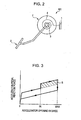
- An accelerator reaction force control apparatus 100 generally controls a reaction force (operational reaction force) of an accelerator 2 provided in a vehicle body 1 of a vehicle (not shown). While the term “accelerator pedal” or “accelerator” is used throughout this specification, it should be understood that such terms should not be limited to any particular embodiment or style of input device. In particular, while a “pedal” inside the passenger compartment is described, it should be understood that the “accelerator” may be a device in the engine compartment responsive to electrical, hydraulic, or mechanical signals produced by a pedal (or other device) in the passenger compartment.
- the accelerator reaction force control apparatus 100 may include means for detecting an opening degree (amount of depression) of the accelerator 2 provided in the vehicle, means for detecting a change rate of the opening degree (speed of depression) of the accelerator 2 provided in the vehicle, and means for changing the reaction force of the accelerator 2 from a basic reaction force.
- the basic reaction force may be an operational reaction force set relative to an amount of depression of the accelerator, such as a conventional accelerator.
- the basic reaction force may be set to be increased depending on the increase of the amount of depression of the accelerator approximately proportionally.
- the reaction force of the accelerator 2 may be increased from the basic reaction force amount.
- the increased reaction force amount is equal to the basic reaction force plus the added reaction force.
- the accelerator 2 may be provided on a rotating shaft 3 such that the accelerator 2 can pivot about the rotating shaft 3.
- the accelerator 2 may receive a reaction force in a closing direction thereof from a return spring 4 which may be fixed to the vehicle body 1 at one end thereof and to the rotating shaft 3 at the other end thereof.
- a return spring 4 which may be fixed to the vehicle body 1 at one end thereof and to the rotating shaft 3 at the other end thereof.
- Various types of springs may be used as the return spring 4.
- the rotating shaft 3 may be rotatably supported by a bearing 5 provided on the vehicle body 1 at one end thereof.
- An accelerator position sensor 6, which may serve as an accelerator-opening-degree detecting means and accelerator-opening-degree change-rate detecting means, may be provided near the other end of the rotating shaft 3.
- the accelerator position sensor 6 may output a signal corresponding to the position (opening degree) of the accelerator 2, and the change rate of the opening degree may be determined from the amount of change in the opening degree within a small period of time.
- an amount of depression of the accelerator 2 may be associated with an opening degree of a throttle valve (not shown) of an internal combustion engine (not shown) so that the throttle valve opening of the internal combustion engine increases in accordance with the amount of depression of the accelerator 2.
- the amount of fuel injection increases in accordance with the accelerator opening degree.
- a reaction-force changing mechanism 101 may include a variable friction plate 7 which may further include a pair of friction members 7a and 7b which face each other and which may apply a frictional force against the rotation of the rotating shaft 3.
- One friction member 7a may be mechanically fixed to an end portion of the rotating shaft 3, and the other friction member 7b may be supported by a fixed shaft 8 with a spline, or the like, provided therebetween so that the friction member 7b may be movable in an axial direction but is not rotatable.
- the fixed shaft 8 may be fixed to and supported by the vehicle body 1.
- An actuator (for example, an electromagnetic solenoid) 9 which is capable of urging the friction member 7b against the friction member 7a may be fixed to the vehicle body 1.
- the actuator 9 may operate to move the friction member 7b in the axial direction (direction shown by the arrow A1 in Figure 1 ), and thereby may change the frictional force applied between the friction member 7a and the friction member 7b.
- the operation of the actuator 9 may be controlled by a control unit 10.
- the control unit 10 may be capable of controlling the operation of the actuator 9 so as to change the reaction force applied to the accelerator 2 against the depression thereof by changing the frictional force applied to the rotating shaft 3.
- the control unit 10 may receive signals from various sensors including the accelerator position sensor 6 which detects the opening degree of the accelerator 2, an acceleration sensor 11 which determines an inclination of a road from an inclination of the vehicle, an atmospheric pressure sensor 12 which detects an ambient atmospheric pressure, an intake air temperature sensor 13 which detects an intake air temperature, a vehicle speed sensor 14 which detects a vehicle speed, a seat pressure sensor 15 which is installed in a vehicle seat (not shown) to detect whether or not an occupant is sitting in the seat, and a gear position sensor 16 which detects a speed-change ratio of a transmission.
- the control unit 10 may also receive information from a car navigation system 17 which may provide a current position of the vehicle and a map of an area around the current position and a signal from a laser radar 18 which may detect a following distance between the vehicle and a vehicle in front.
- the transmission may be, for example, a continuously variable transmission capable of continuously varying the gear ratio.
- the transmission may also be an automatic transmission including a multi-speed auxiliary transmission and a torque converter or a manual transmission.
- the speed-change ratio may be determined as a ratio between rotational speeds of an input shaft and an output shaft.
- FIG 3 schematically shows the characteristic of the accelerator reaction force according to a first exemplary embodiment.
- the basic reaction force substantially changes in proportion to the accelerator opening degree with a suitable hysteresis depending on whether the accelerator is operated in an opening-degree-increasing direction or in an opening-degree-reducing direction.
- the accelerator opening degree is increased, that is, when the accelerator is depressed, and the accelerator opening degree exceeds a predetermined accelerator-opening-degree threshold (denoted by SL in Figure 3 )
- the accelerator reaction force is increased stepwise from the basic reaction force.
- the shaded area B corresponds to the increase in the accelerator reaction force.
- the increase in the reaction force of the accelerator 2 for the accelerator-opening-degree increasing direction may be immediately eliminated when, for example, the operating direction of the accelerator 2 is changed to an accelerator-opening-degree reducing direction.
- the increase in the reaction force of the accelerator 2 for the accelerator-opening-degree increasing direction may be eliminated when the accelerator-opening-degree is reduced and becomes equal to or less than the above-described predetermined accelerator-opening-degree threshold.
- the control unit 10 may change the accelerator-opening-degree threshold at which the reaction force of the accelerator 2 is increased as follows. That is, the accelerator-opening-degree threshold may be changed in accordance with a vehicle speed at the time when the operation of increasing the opening degree of the accelerator 2 is started by the driver, that is, in accordance with an initial vehicle speed at the time when the accelerator 2 is depressed from a completely closed state or a partially opened state. More specifically, if the vehicle speed at the time when the opening degree of the accelerator 2 starts to increase is low, a first accelerator-opening-degree threshold, which is relatively low, may be selected. If the vehicle speed at the time when the opening degree of the accelerator 2 starts to increase is high, a second accelerator-opening-degree threshold, which is relatively high, may be selected.
- the reaction force may be increased at a relatively small accelerator opening degree. Therefore, a reaction-force increasing range between the accelerator-opening-degree threshold and a maximum accelerator opening degree is large. In contrast, in the case where the vehicle speed is high at the time when the operation of increasing the opening degree of the accelerator 2 is started, the reaction force is not increased until the accelerator opening degree exceeds a relatively large accelerator opening degree. Therefore, a reaction-force non-increasing range between the accelerator opening degree corresponding to the completely closed state and the accelerator-opening-degree threshold is relatively large.
- the accelerator-opening-degree threshold may continuously change from the first accelerator-opening-degree threshold to the second accelerator-opening-degree threshold in accordance with the vehicle speed, as shown in Figure 4 .
- Figure 4 is a schematic diagram illustrating the relationship between the accelerator-opening-degree threshold, the driving force characteristic at the maximum accelerator opening degree obtained under the assumption that speed change control is suitably performed, and the driving resistance, with respect to the vehicle speed represented by the horizontal axis.
- the speed-change ratio of the transmission is high. Therefore, the vehicle driving force obtained at the maximum accelerator opening degree is relatively large. Because a large vehicle driving force is generated even when the amount of operation of the accelerator is small, there is a high possibility that excessive vehicle driving force will be generated and unnecessary acceleration may be performed.
- the accelerator-opening-degree threshold may be set to the first accelerator-opening-degree threshold, which is relatively low. Because the reaction force of the accelerator 2 is increased at a relatively small accelerator opening degree, excessive depression of the accelerator 2 by the driver may be suppressed and the overall fuel consumption may be reduced.
- the speed-change ratio of the transmission is low. Therefore, the vehicle driving force obtained at the maximum accelerator opening degree is relatively small, and an amount of increase in the vehicle driving force corresponding to a certain amount of operation of the accelerator is also relatively small. Therefore, unnecessary acceleration does not easily occur.
- the driving resistance (air resistance and rolling resistance) of the vehicle is high, and therefore a large driving force may be required to maintain the vehicle speed.
- an allowance driving force which is a difference between the vehicle driving force at the maximum accelerator opening degree and the driving resistance, is small. If the reaction force of the accelerator 2 is increased in this state, it becomes difficult to further depress the accelerator 2 and the vehicle may not be accelerated.
- the accelerator-opening-degree threshold may be set to the second accelerator-opening-degree threshold, which is relatively high.
- the reaction force may be maintained at the basic reaction force and quick depression of the accelerator 2 may be allowed until the accelerator opening degree exceeds a relatively large accelerator opening degree. As a result, the vehicle may be smoothly accelerated.
- the accelerator-opening-degree threshold may continuously change between the first accelerator-opening-degree threshold and the second accelerator-opening-degree threshold in accordance with the vehicle speed. Therefore, the accelerator 2 may be operated without making the driver feel an uncomfortable sensation. Even when the vehicle speed is at the boundary between the low vehicle speed range and the intermediate-to-high vehicle speed range, the accelerator-opening-degree threshold is not changed stepwise at a certain vehicle speed. Therefore, the driver may operate the accelerator 2 without feeling an uncomfortable sensation.
- the accelerator-opening-degree threshold may be set based on two stages, that is, between the first accelerator-opening-degree threshold and the second accelerator-opening-degree threshold.
- the accelerator-opening-degree threshold may also be set based on three or more stages.
- the accelerator-opening-degree threshold may be set such that the accelerator-opening-degree threshold is continuously changed over the entire vehicle speed range.
- the vehicle speed is used as a parameter which shows the driving resistance of the vehicle and the driving force characteristic at the maximum accelerator opening degree. Therefore, the accelerator-opening-degree threshold is substantially set in consideration of both the driving resistance of the vehicle and the driving force characteristic at the maximum accelerator opening degree.
- the accelerator-opening-degree threshold may also be set on the basis of only the driving force characteristic at the maximum accelerator opening degree.
- the speed-change ratio of the transmission may be used as a parameter which shows the driving force characteristic at the maximum accelerator opening degree
- the accelerator-opening-degree threshold may be set in accordance with the current speed-change ratio.
- Figure 4 shows the driving force characteristic at the maximum accelerator opening degree in the case where, for example, the transmission is a continuously variable transmission.
- the driving force characteristic with respect to the vehicle speed in the case where the transmission is an automatic transmission including a multi-speed auxiliary transmission or a manual transmission is basically similar to the driving force characteristic shown in Figure 4 . More specifically, the vehicle driving force is large in the low vehicle speed range because the speed-change ratio is high, and the vehicle driving force is small in the intermediate-to-high vehicle speed range because the speed-change ratio is low. Therefore, in the case where, for example, the transmission is a multi-speed transmission, the accelerator-opening-degree threshold may be selected from a plurality of thresholds in accordance with the speed-change ratio of the transmission.
- the accelerator-opening-degree threshold may also be set using a parameter other than the vehicle speed as a parameter which shows the driving resistance.
- the driving resistance of the vehicle increases when the inclination of the road (the sign of the inclination is positive for the ascending road) is large or when the weight of load on the vehicle is large (for example, when a large number of people are on board). Therefore, the accelerator-opening-degree threshold for when the inclination is large may be set to be higher than the accelerator-opening-degree threshold for when the inclination is small.
- the accelerator-opening-degree threshold for when the weight of the load is large may be set to be higher than the accelerator-opening-degree threshold for when the weight of the load is small.
- the inclination of the road may be determined from a detection value obtained by the acceleration sensor 11 (inclination detecting means).
- the acceleration sensor 11 inclination detecting means
- the inclination of the road on which the vehicle is currently traveling may also be determined from the map information.
- the number of people on board may be determined from, for example, a signal from the seat pressure sensor 15 placed in each seat (vehicle load-weight detecting means).
- the accelerator-opening-degree threshold may be set on the basis of the driving resistance of the vehicle or the driving force characteristic at the maximum accelerator opening degree.
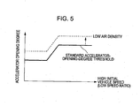
- the determined accelerator-opening-degree threshold may also be corrected in accordance with other factors, as shown in Figure 5 .
- the accelerator-opening-degree threshold may be corrected in accordance with, for example, a density of air introduced into the internal combustion engine, a driving mode, such as a sports mode and an economy mode, a following distance behind a vehicle in front, or a difference between the current speed and a legal speed.
- the correction based on the air density may be performed to compensate for a reduction in the output of the internal combustion engine due to a reduction in the air density, which may occur in a high-altitude environment or a high-temperature environment.
- the accelerator-opening-degree threshold is increased as the air density decreases.
- the air density may be determined by a known detection method on the basis of an ambient atmospheric pressure and an ambient temperature at the place where the vehicle is currently located (air-density detecting means).
- the altitude of the position where the vehicle is currently located may be calculated from a detection value obtained by the atmospheric pressure sensor 12.
- the altitude of the current position may be determined from the map information.
- the ambient temperature may be determined from a detection value obtained by the intake air temperature sensor 13.
- the air density may also be directly determined from the detection value obtained by the atmospheric pressure sensor 12.
- the accelerator-opening-degree threshold is increased, as in the case shown in Figure 5 , when the current driving mode is a mode which requires high acceleration performance.
- a speed-changing pattern or the like of the automatic transmission may be changed in accordance with the driving mode.
- the driving mode of the vehicle may be easily determined from the position of the driving-mode selection switch 19 (driving-mode determining means).
- the accelerator-opening-degree threshold for when the driving mode which requires high acceleration performance (for example, a sports mode) is selected by the switch operation may be set to be higher than the accelerator-opening-degree threshold for when a normal driving mode is selected.
- the driving tendency of the driver may be learned from the driving history of the driver, and it may be determined that the driver prefers a driving style which requires high acceleration performance if the driver tends to depress the accelerator 2 by a large amount. In such a case, it may be assumed that the driving mode which requires high acceleration performance is constantly selected.
- the accelerator-opening-degree threshold may be increased as the following distance increases.
- the following distance behind the vehicle in front may be detected by a following-distance detecting device which uses the laser radar 18.
- the following-distance detecting device determines the following distance behind the vehicle in front by emitting a laser beam toward the vehicle in front and receiving the laser beam reflected by the vehicle in front.
- the accelerator-opening-degree threshold may also be corrected on the basis of the difference between the current vehicle speed and the legal speed for the road on which the vehicle is currently traveling.
- the current vehicle speed is lower than the legal speed.
- the current position and the map information of the area around the current position may be obtained from the car navigation system 17, and the legal speed for the road on which the vehicle is currently traveling is determined from the map information (legal-speed detecting means).
- the correction may be performed such that the accelerator-opening-degree threshold is increased as the difference between the legal speed and the current vehicle speed increases. This correction may be performed to allow smooth acceleration to the legal speed and suppress the acceleration when the vehicle speed is equal to or higher than the legal speed.
- the accelerator-opening-degree threshold determined on the basis of the driving resistance or the driving force characteristic at the maximum accelerator opening degree may be corrected on the basis of, for example, the air density, the driving mode, the following distance behind the vehicle in front, or the difference between the current vehicle speed and the legal speed.
- the reaction force of the accelerator 2 may be adequately increased and the vehicle may be smoothly driven in accordance with the intention of the driver.
- the problem that the vehicle may not be accelerated as intended by the driver when, for example, a relatively large driving force is required to accelerate the vehicle may be prevented.
- the vehicle may be prevented from giving the driver a wrong impression that the vehicle simply has poor acceleration performance.
- FIG. 6 is a flowchart of an accelerator reaction force control process according to the present disclosure. The flowchart will now be described.
- Step 1 the vehicle speed at the time when the opening degree of the accelerator 2 has started to increase is detected. Then, a standard accelerator-opening-degree threshold (a base accelerator-opening-degree threshold) is set in accordance with the vehicle speed, as described above.
- the accelerator-opening-degree threshold may be corrected in accordance with the driving mode. More specifically, the standard accelerator-opening-degree threshold obtained in Step 1 may corrected such that the accelerator-opening-degree threshold is increased if the current driving mode is a driving mode which requires high acceleration performance.
- the accelerator-opening-degree threshold may be corrected in accordance with the ambient air density. More specifically, the accelerator-opening-degree threshold may be further corrected such that the accelerator-opening-degree threshold is increased as the air density decreases.
- Step 4 the correction based on the inclination of the road on which the vehicle is currently traveling and the weight of the load on the vehicle is performed. More specifically, the accelerator-opening-degree threshold may be further corrected such that the accelerator-opening-degree threshold is increased as the inclination of the road increases and as the weight of the load increases.
- Step 5 the correction based on the following distance behind the vehicle in front is performed. More specifically, the accelerator-opening-degree threshold may be further corrected such that the accelerator-opening-degree threshold is increased as the following distance behind the vehicle in front increases.
- Step 6 the correction based on the difference between the current vehicle speed and the legal speed is performed. More specifically, assuming that the current vehicle speed is lower than the legal speed for the road on which the vehicle is currently traveling, the accelerator-opening-degree threshold may be further corrected such that the accelerator-opening-degree threshold is increased as the difference between the legal speed and the current vehicle speed increases.
- the corrections may be performed by suitable methods, such as multiplication by a correction coefficient or addition of an amount of correction.
- Step 7 the actual opening degree of the accelerator 2, which may be constantly detected, is compared with the final accelerator-opening-degree threshold determined by performing Steps 1 through 6. In the case where the opening degree of the accelerator 2 is larger than the accelerator-opening-degree threshold, the process proceeds to Step 8, where the reaction force of the accelerator 2 is increased from the basic reaction force.
- the accelerator-opening-degree threshold is set in accordance with the initial vehicle speed at the time when the accelerator 2 is operated by the driver in the opening-degree-increasing direction (when the accelerator 2 is depressed from a completely closed state or a partially opened state).
- the accelerator-opening-degree threshold may also be set by constantly detecting the vehicle speed while the opening degree of the accelerator 2 is being increased.
- Figure 7 schematically shows the characteristic of the accelerator reaction force according to a second exemplary embodiment.
- the basic reaction force may substantially change in proportion to the accelerator opening degree with a suitable hysteresis depending on whether the opening is increased or reduced.
- the accelerator reaction force may be increased stepwise from the basic reaction force, as shown by the dashed line, provided that the accelerator opening degree exceeds a predetermined accelerator opening degree and an accelerator-opening-degree change rate exceeds a predetermined change-rate threshold.
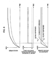
- Figure 8 is a time chart showing the example in which the accelerator reaction force is increased in accordance with the accelerator-opening-degree change rate after the vehicle is started from a stopped state.
- the reaction force of the accelerator 2 may be increased, as shown by the solid line in Figure 8 . If the depressing speed of the accelerator 2, that is, the accelerator-opening-degree change rate, is equal to or lower than the predetermined change-rate threshold, the reaction force of the accelerator 2 may not be increased, as shown by the dashed line in Figure 8 .
- the increase in the reaction force of the accelerator 2 for the accelerator-opening-degree increasing direction may be immediately eliminated when, for example, the operating direction of the accelerator 2 is changed to an accelerator-opening-degree reducing direction, or when the accelerator opening degree is reduced and becomes equal to or less than the above-described predetermined accelerator-opening-degree threshold.
- the depressing speed of the accelerator 2 that is, the accelerator-opening-degree change rate
- the accelerator-opening-degree change rate is a rate of change in the accelerator opening degree with time, and is represented by an inclination of the accelerator opening degree curve in Figure 8 . If the inclination is small, it means that the accelerator 2 is slowly depressed. If the inclination is large, it means that the accelerator 2 is quickly depressed.
- the control unit 10 may change the change-rate threshold at which the reaction force of the accelerator 2 is increased as follows. That is, the change-rate threshold may be changed in accordance with a vehicle speed at the time when the operation of increasing the opening degree of the accelerator 2 is started by the driver, that is, in accordance with an initial vehicle speed at the time when the accelerator 2 is depressed from a completely closed state or a partially opened state. More specifically, if the vehicle speed at the time when the opening degree of the accelerator 2 starts to increase is low, a first change-rate threshold, which is relatively low, may be selected. If the vehicle speed at the time when the opening degree of the accelerator 2 starts to increase is high, a second change-rate threshold, which is relatively high, may be selected.
- the reaction force may be increased at a relatively small accelerator-opening-degree change rate. Therefore, a reaction-force increasing range shown by the shaded area in Figure 9 is large. In contrast, in the case where the vehicle speed is high at the time when the operation of increasing the opening degree of the accelerator 2 is started, the reaction force may not increase until the accelerator-opening-degree change rate exceeds a relatively high accelerator-opening-degree change rate. Therefore, a reaction-force non-increasing range in which the reaction force is not increased is relatively large.
- the change-rate threshold may continuously change from the first change-rate threshold to the second change-rate threshold in accordance with the vehicle speed, as shown in Figure 9 .
- Figure 9 is a schematic diagram illustrating the relationship between the change-rate threshold, the driving force characteristic at the maximum accelerator opening degree obtained under the assumption that speed change control is suitably performed, and the driving resistance, with respect to the vehicle speed represented by the horizontal axis.
- the speed-change ratio of the transmission is high. Therefore, the vehicle driving force obtained at the maximum accelerator opening degree is large. Because a large vehicle driving force is generated even when the amount of operation of the accelerator is small, there is a high possibility that excessive vehicle driving force may be generated and unnecessary acceleration may be performed.
- the change-rate threshold may be set to the first change-rate threshold, which is relatively low. Because the reaction force of the accelerator 2 is increased at a relatively small accelerator-opening-degree change rate, excessive depression of the accelerator 2 by the driver may be suppressed and the overall fuel consumption may be reduced.
- the speed-change ratio of the transmission is low. Therefore, the vehicle driving force obtained at the maximum accelerator opening degree is small, and an amount of increase in the vehicle driving force corresponding to a certain amount of operation of the accelerator is also relatively small. Therefore, unnecessary acceleration may not easily occur.
- the driving resistance (air resistance and rolling resistance) of the vehicle is high, and therefore a large driving force is required to maintain the vehicle speed.
- an allowance driving force which is a difference between the vehicle driving force at the maximum accelerator opening degree and the driving resistance, is small. If the reaction force of the accelerator 2 is increased in this state, it may become difficult to further depress the accelerator 2 and the vehicle may not be accelerated.
- the change-rate threshold is set to the second change-rate threshold, which is relatively high.
- the reaction force may be maintained at the basic reaction force and quick depression of the accelerator 2 may be allowed until the accelerator-opening-degree change rate exceeds a relatively large change rate. As a result, the vehicle may be smoothly accelerated.
- the change-rate threshold may continuously change between the first change-rate threshold and the second change-rate threshold in accordance with the vehicle speed. Therefore, the accelerator 2 may be operated without making the driver feel an uncomfortable sensation. Even when the vehicle speed is at the boundary between the low vehicle speed range and the intermediate-to-high vehicle speed range, the change-rate threshold is not changed stepwise at a certain vehicle speed. Therefore, the driver may operate the accelerator 2 without feeling an uncomfortable sensation.
- the change-rate threshold is set based on two stages, that is, between the first change-rate threshold and the second change-rate threshold.
- the present disclosure is not limited to this, and the change-rate threshold may also be set based on three or more stages.
- the change-rate threshold may be set such that the change-rate threshold is continuously changed over the entire vehicle speed range.
- the vehicle speed is used as a parameter which shows the driving resistance of the vehicle and the driving force characteristic at the maximum accelerator opening degree. Therefore, the change-rate threshold is substantially set in consideration of both the driving resistance of the vehicle and the driving force characteristic at the maximum accelerator opening degree. However, the change-rate threshold may also be set on the basis of only the driving force characteristic at the maximum accelerator opening degree.
- the speed-change ratio of the transmission may be used as a parameter which shows the driving force characteristic at the maximum accelerator opening degree, and the change-rate threshold may be set in accordance with the current speed-change ratio.
- Figure 9 shows the driving force characteristic at the maximum accelerator opening degree in the case where, for example, the transmission is a continuously variable transmission.
- the driving force characteristic with respect to the vehicle speed in the case where the transmission is an automatic transmission including a multi-speed auxiliary transmission or a manual transmission is basically similar to the driving force characteristic shown in Figure 9 . More specifically, the vehicle driving force is large in the low vehicle speed range because the speed-change ratio is high, and the vehicle driving force is small in the intermediate-to-high vehicle speed range because the speed-change ratio is low. Therefore, in the case where, for example, the transmission is a multi-speed transmission, the change-rate threshold may be selected from a plurality of thresholds in accordance with the speed-change ratio of the transmission.
- the change-rate threshold may also be set using a parameter other than the vehicle speed as a parameter which shows the driving resistance.
- the driving resistance of the vehicle increases when the inclination of the road (the sign of the inclination is positive for the ascending road) is large or when the weight of load on the vehicle is large (for example, when a large number of people are on-board the vehicle). Therefore, the change-rate threshold for when the inclination is large may be set to be higher than the change-rate threshold for when the inclination is small. In addition, the change-rate threshold for when the weight of the load is large may be set to be higher than the change-rate threshold for when the weight of the load is small.
- the change-rate threshold may be set on the basis of the driving resistance of the vehicle or the driving force characteristic at the maximum accelerator opening degree.
- the determined change-rate threshold may also be corrected in accordance with other factors, as shown in Figure 5 .
- the change-rate threshold may be corrected in accordance with, for example, a density of air introduced into the internal combustion engine, a driving mode, such as a sports mode and an economy mode, a following distance behind a leading vehicle, or a difference between the current speed and a legal speed limit.
- the correction based on the air density may be performed to compensate for a reduction in the output of the internal combustion engine due to a reduction in the air density, which may occur in a high-altitude environment or a high-temperature environment. As shown by the dashed line in Figure 10 , the change-rate threshold is increased as the air density decreases.
- the change-rate threshold may be increased, as in the case shown in Figure 10 , when the current driving mode is a mode which requires high acceleration performance.
- the change-rate threshold may be increased as the following distance increases.
- the change-rate threshold may also be corrected on the basis of the difference between the current vehicle speed and the legal speed for the road on which the vehicle is currently traveling. Assuming that the current vehicle speed is lower than the legal speed, the correction may be performed such that the change-rate threshold is increased as the difference between the legal speed and the current vehicle speed increases.
- the change-rate threshold determined on the basis of the driving resistance or the driving force characteristic at the maximum accelerator opening degree may be corrected on the basis of, for example, the air density, the driving mode, the following distance behind the vehicle in front, and the difference between the current vehicle speed and the legal speed.
- the reaction force of the accelerator 2 may be adequately increased and the vehicle may be smoothly driven in accordance with the intention of the driver.
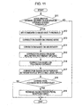
- FIG 11 is a flowchart of an accelerator reaction force control process according to the present embodiment. The flowchart will now be described.
- Step 11 it is determined whether or not the current position of the accelerator 2, that is, the current accelerator opening degree, exceeds a predetermined accelerator-opening-degree threshold.
- the process proceeds to Step 12 if the current accelerator opening degree exceeds the predetermined accelerator-opening-degree threshold. If the current accelerator opening degree is equal to or less than the predetermined accelerator-opening-degree threshold, the routine is terminated. If the accelerator opening degree is sufficiently small, no acceleration which reduces the fuel efficiency may be performed. Therefore, according to the present exemplary embodiment, the process of increasing the reaction force is not performed irrespective of the accelerator-opening-degree change rate.
- Step 12 the vehicle speed at the time when the opening degree of the accelerator 2 has started to increase is detected. Then, a standard change-rate threshold (a base change-rate threshold) is set in accordance with the vehicle speed, as described above.
- Step 13 the change-rate threshold is corrected in accordance with the driving mode. More specifically, the standard change-rate threshold obtained in Step 12 is corrected such that the change-rate threshold is increased if the current driving mode is a driving mode which requires high acceleration performance.
- Step 14 the change-rate threshold is corrected in accordance with the ambient air density. More specifically, the change-rate threshold is further corrected such that the change-rate threshold is increased as the air density decreases.
- Step 15 the correction based on the inclination of the road on which the vehicle is currently traveling and the weight of the load on the vehicle is performed. More specifically, the change-rate threshold is further corrected such that the change-rate threshold is increased as the inclination of the road increases and as the weight of the load increases.
- Step 16 the correction based on the following distance behind the vehicle in front is performed. More specifically, the change-rate threshold is further corrected such that the change-rate threshold is increased as the following distance behind the vehicle in front increases.
- Step 17 the correction based on the difference between the current vehicle speed and the legal speed is performed. More specifically, assuming that the current vehicle speed is lower than the legal speed for the road on which the vehicle is currently traveling, the change-rate threshold is further corrected such that the change-rate threshold is increased as the difference between the legal speed and the current vehicle speed increases.
- the corrections may be performed by suitable methods, such as multiplication by a correction coefficient or addition of an amount of correction.
- Step 18 the actual change rate of the opening degree of the accelerator 2, which is constantly calculated, is compared with the final change-rate threshold determined by performing Steps 12 through 17. In the case where the change rate of the opening degree of the accelerator 2 is larger than the change-rate threshold, the process proceeds to Step 19, where the reaction force of the accelerator 2 is increased from the basic reaction force.
- the change-rate threshold is set in accordance with the initial vehicle speed at the time when the accelerator 2 is operated by the driver in the opening-degree-increasing direction (when the accelerator 2 is depressed from a completely closed state or a partially opened state).
- the change-rate threshold may also be set by constantly detecting the vehicle speed while the opening degree of the accelerator 2 is being increased.
- the specific fuel consumption changes in accordance with the opening degree of the accelerator 2, and the instantaneous specific fuel consumption may be calculated from the opening degree of the accelerator 2 and the change rate thereof.
- the thus-calculated specific fuel consumption may be displayed on an instrument panel in front of the driver's seat or on a car navigation screen. In such a case, the driver may drive the vehicle while visually recognizing that the reaction force of the accelerator 2 increases when the fuel efficiency decreases. Therefore, the fuel consumption may be effectively reduced.
- the reaction force is increased in accordance with the accelerator opening degree or the change rate of the accelerator opening degree which affects the fuel consumption.
- the present disclosure may also be applied to the case in which a threshold is set directly for the specific fuel consumption and the reaction force is increased when the current specific fuel consumption exceeds the threshold.
- the position of the accelerator 2 itself (amount of depression) is detected as the accelerator opening degree. Therefore, in the above-described exemplary embodiment, the amount of depression of the accelerator 2 is substantially equivalent to the accelerator opening degree, and the change rate in the position of the accelerator 2 is substantially equivalent to the accelerator-opening-degree change rate.
- the control operation according to the present disclosure may also be performed by using, for example, an opening degree of the throttle valve, which is operationally associated with the accelerator 2, as the accelerator opening degree.
- the vehicle in which the accelerator reaction force control apparatus according to the present disclosure is used is not limited to a vehicle having an internal combustion engine as a drive source.
- the accelerator reaction force control apparatus according to the present disclosure may also be used in an electric automobile or a hybrid automobile.
- an accelerator reaction force control apparatus may set an accelerator reaction force to be greater than a basic reaction force when an accelerator opening degree exceeds an accelerator-opening-degree threshold or when a change rate in the accelerator opening degree exceeds a predetermined change-rate threshold.
- the accelerator-opening-degree threshold or the change-rate threshold may be set in consideration of the driving force characteristics of the vehicle at a predetermined accelerator opening degree.
- the accelerator-opening-degree threshold or the change-rate threshold may be set in accordance with the driving force characteristics of the vehicle.
- the accelerator-opening-degree threshold or the change-rate threshold for when the vehicle driving force at the predetermined accelerator opening degree is relatively small may be higher than the accelerator-opening-degree threshold or the change-rate threshold for when the vehicle driving force at the predetermined accelerator opening degree is relatively large.
- the reaction force of the accelerator may be increased from the basic reaction force if the accelerator opening degree exceeds the predetermined accelerator-opening-degree threshold or if the change rate of the accelerator opening degree exceeds the predetermined change-rate threshold. Therefore, excessive depression of the accelerator may be suppressed and fuel consumption may be reduced.
- the accelerator-opening-degree threshold or the change-rate threshold may be increased in such a case.
- the reaction force may be maintained at the basic reaction force until the accelerator opening degree exceeds a relatively large accelerator opening degree.
- the vehicle may be accelerated as intended by the driver.
Claims (10)
- Dispositif de commande d'un véhicule, comprenant :un détecteur pour détecter un degré d'ouverture d'un accélérateur (2) ; etun contrôleur (10) pour ajuster une force de réaction de l'accélérateur (2),dans lequel le contrôleur (10) est configuré pour augmenter la force de réaction de l'accélérateur (2) quand le degré d'ouverture de l'accélérateur excède une valeur seuil (SL) ;caractérisé en ce queune valeur seuil à une plage de vitesse de véhicule basse incluant un temps de démarrage est définie comme une première valeur seuil et une valeur seuil à une plage de vitesse de véhicule élevée est définie comme une seconde valeur seuil, eten ce que la seconde valeur seuil est supérieure à la première valeur seuil, la valeur seuil variant continuellement de la première valeur seuil à la seconde valeur seuil.
- Dispositif de commande selon la revendication 1, dans lequel la valeur seuil comprend au moins un d'un seuil de degré d'ouverture d'accélérateur (SL) et d'un seuil de variation de taux d'accélérateur.
- Dispositif de commande selon la revendication 1, dans lequel une valeur seuil quand le rapport de variations de vitesse est élevé est défini comme la première valeur seuil et une valeur seuil quand le rapport de variations de vitesse est bas est défini comme la seconde valeur seuil, dans lequel la seconde valeur seuil est supérieure à la première valeur seuil.
- Dispositif de commande selon la revendication 1, dans lequel la valeur seuil quand une inclinaison d'une route est grande est élevée par rapport à la valeur seuil quand l'inclinaison de la route est petite.
- Dispositif de commande selon la revendication 1, dans lequel la valeur seuil quand un poids de charge du véhicule est grand est élevée par rapport à la valeur seuil quand le poids de charge du véhicule est petit.
- Dispositif de commande selon la revendication 1, dans lequel la valeur seuil est réglée plus élevée pour un mode de traction dans lequel la demande accélération du véhicule est plus élevée.
- Dispositif de commande selon la revendication 1, dans lequel la valeur seuil est réglée plus élevée lorsqu'une distance entre le véhicule et le véhicule précédent est plus grande.
- Dispositif de commande selon la revendication 1, dans lequel la valeur seuil est réglée plus élevée lorsqu'une différence de vitesse entre la vitesse du véhicule actuelle et une vitesse légale pour la route sur laquelle le véhicule circule actuellement est plus grande.
- Dispositif de commande selon la revendication 1, dans lequel la valeur seuil est augmentée lorsqu'une densité d'air diminue.
- Procédé pour commander un véhicule, le procédé comprenant :la détection d'un degré d'ouverture d'un accélérateur (2) ;l'ajustement d'une force de réaction de l'accélérateur (2) ;caractérisé en ce que la force de réaction de l'accélérateur (2) est augmentée quand le degré d'ouverture de l'accélérateur (2) excède une première valeur seuil à une plage de vitesse du véhicule basse incluant un temps de démarrage du véhicule et la force de réaction de l'accélérateur (2) est augmentée quand le degré d'ouverture de l'accélérateur (2) excède une seconde valeur seuil à une plage de vitesse du véhicule élevée, et en ce quela seconde valeur seuil est réglée plus élevée que la première valeur seuil, la valeur seuil variant continuellement de la première valeur seuil à la seconde valeur seuil.
Applications Claiming Priority (5)
| Application Number | Priority Date | Filing Date | Title |
|---|---|---|---|
| JP2008197383 | 2008-07-31 | ||
| JP2008197384 | 2008-07-31 | ||
| JP2009123000A JP5326805B2 (ja) | 2008-07-31 | 2009-05-21 | アクセルペダル踏力制御装置 |
| JP2009122999A JP5381321B2 (ja) | 2008-07-31 | 2009-05-21 | アクセルペダル踏力制御装置 |
| PCT/IB2009/006423 WO2010013133A1 (fr) | 2008-07-31 | 2009-07-31 | Réaction d'accélérateur pour appareil de commande |
Publications (3)
| Publication Number | Publication Date |
|---|---|
| EP2318229A1 EP2318229A1 (fr) | 2011-05-11 |
| EP2318229A4 EP2318229A4 (fr) | 2014-03-19 |
| EP2318229B1 true EP2318229B1 (fr) | 2014-10-22 |
Family
ID=42069075
Family Applications (1)
| Application Number | Title | Priority Date | Filing Date |
|---|---|---|---|
| EP09802585.1A Active EP2318229B1 (fr) | 2008-07-31 | 2009-07-31 | Réaction d'accélérateur pour appareil de commande |
Country Status (9)
| Country | Link |
|---|---|
| US (1) | US9533572B2 (fr) |
| EP (1) | EP2318229B1 (fr) |
| JP (2) | JP5381321B2 (fr) |
| KR (1) | KR101379104B1 (fr) |
| CN (1) | CN102112336B (fr) |
| BR (1) | BRPI0916459A2 (fr) |
| MX (1) | MX2011001136A (fr) |
| RU (1) | RU2466881C2 (fr) |
| WO (1) | WO2010013133A1 (fr) |
Families Citing this family (34)
| Publication number | Priority date | Publication date | Assignee | Title |
|---|---|---|---|---|
| JP5302095B2 (ja) * | 2009-05-13 | 2013-10-02 | 本田技研工業株式会社 | 車両の燃料消費率向上支援装置 |
| FR2956756B1 (fr) * | 2010-02-23 | 2012-08-24 | Airbus Operations Sas | Dispositif generateur de couple resistif perfectionne |
| JP5471829B2 (ja) * | 2010-05-25 | 2014-04-16 | 日産自動車株式会社 | ハイブリッド車両のアクセルペダル踏力制御装置 |
| JP5471856B2 (ja) | 2010-06-07 | 2014-04-16 | 日産自動車株式会社 | アクセルペダル踏力制御装置及びアクセルペダル踏力制御方法 |
| EP2583853B1 (fr) * | 2010-06-15 | 2017-10-11 | Nissan Motor Co., Ltd | Procédé de réglage de force d'appui sur pédale d'accélération pour dispositif de commande de force d'appui sur pédale d'accélération |
| DE102010041537B4 (de) * | 2010-09-28 | 2021-04-15 | Bayerische Motoren Werke Aktiengesellschaft | Fahrerassistenzsystem zur Unterstützung des Fahrers zum verbrauchskontrollierten Fahren |
| DE102010041544B4 (de) | 2010-09-28 | 2023-05-04 | Bayerische Motoren Werke Aktiengesellschaft | Fahrerassistenzsystem zur Unterstützung des Fahrers zum verbrauchskontrollierten Fahren |
| JP5206802B2 (ja) * | 2011-01-20 | 2013-06-12 | トヨタ自動車株式会社 | 車両の走行制御装置 |
| JP5740175B2 (ja) * | 2011-02-21 | 2015-06-24 | 株式会社ミクニ | アクセルペダル装置 |
| JP4881482B1 (ja) * | 2011-06-02 | 2012-02-22 | 有限会社ジロウコレクション | 車輌用アクセルペダル踏み圧調節システム |
| US9176515B2 (en) * | 2011-07-05 | 2015-11-03 | Honda Motor Co., Ltd. | Accelerator pedal reaction force control device |
| DE102011088275A1 (de) * | 2011-12-12 | 2013-06-13 | Robert Bosch Gmbh | Fahrpedalsystem für ein Fahrzeug |
| CN104755305B (zh) | 2012-11-21 | 2017-06-13 | 本田技研工业株式会社 | 油门踏板反力控制装置及车辆 |
| KR101406489B1 (ko) * | 2013-04-23 | 2014-06-12 | 기아자동차주식회사 | 가속페달 장치의 답력 능동 조절방법 |
| RU2529923C1 (ru) * | 2013-04-25 | 2014-10-10 | федеральное государственное бюджетное образовательное учреждение высшего профессионального образования "Южно-Российский государственный технический университет (Новочеркасский политехнический институт)" | Устройство для управления многодвигательными электроприводами постоянного тока |
| DE102013214371A1 (de) * | 2013-07-23 | 2015-01-29 | Robert Bosch Gmbh | Haptisches Kraftfahrzeug-Fahrpedal mit elastisch angekoppeltem Aktuator sowie Verfahren und Regelungseinheit zum Regeln desselben |
| GB201318706D0 (en) * | 2013-10-23 | 2013-12-04 | Jaguar Land Rover Ltd | Improvements in vehicle speed control |
| US10025341B2 (en) * | 2013-10-30 | 2018-07-17 | Honda Motor Co., Ltd. | Pedal reactive force controller |
| EP3751181B1 (fr) | 2014-01-31 | 2022-01-12 | BRP-Rotax GmbH & Co. KG | Procédé de fonctionnement d'un véhicule |
| US9908409B2 (en) | 2014-08-29 | 2018-03-06 | Mazda Motor Corporation | Vehicle accelerator pedal reaction force control device |
| WO2016045687A1 (fr) * | 2014-09-24 | 2016-03-31 | Volvo Truck Corporation | Procédé pour commander la force de réaction d'un système de pédale d'accélération |
| JP6480762B2 (ja) * | 2015-03-06 | 2019-03-13 | 株式会社Subaru | 内燃機関の制御装置 |
| RU2676749C2 (ru) * | 2016-08-26 | 2019-01-11 | Вячеслав Иванович Новоковский | Способ регулирования двигателя внутреннего сгорания при эксплуатации |
| JP6787040B2 (ja) * | 2016-10-27 | 2020-11-18 | 株式会社アドヴィックス | 車両用操作装置 |
| JP6702157B2 (ja) * | 2016-11-25 | 2020-05-27 | トヨタ自動車株式会社 | アクセルペダルの反力付与装置 |
| CN110062842B (zh) * | 2016-12-07 | 2021-07-30 | 马自达汽车株式会社 | 车辆用控制装置 |
| JP2018149933A (ja) * | 2017-03-14 | 2018-09-27 | オムロン株式会社 | 制御装置、プログラム、支援装置および支援方法 |
| EP3656596A4 (fr) * | 2017-07-20 | 2021-03-24 | Mitsuba Corporation | Dispositif de prévention de démarrage soudain |
| KR20190049004A (ko) * | 2017-11-01 | 2019-05-09 | 현대자동차주식회사 | 차량 및 그 제어방법. |
| JP2019143539A (ja) * | 2018-02-21 | 2019-08-29 | 本田技研工業株式会社 | 車両 |
| KR102637599B1 (ko) * | 2018-10-08 | 2024-02-19 | 주식회사 에이치엘클레무브 | 차량간 통신 정보를 이용한 차선변경 제어장치 및 방법과, 그를 위한 성향 정보 산출 장치 |
| DE112019006781T5 (de) * | 2019-02-01 | 2021-10-21 | Mikuni Corporation | Fahrpedalvorrichtung |
| KR102163963B1 (ko) * | 2019-04-23 | 2020-10-13 | 현대자동차주식회사 | 자동차의 페달 답력 제어 시스템 및 방법 |
| JP2023031743A (ja) * | 2021-08-25 | 2023-03-09 | 株式会社デンソー | アクセルペダルシステム |
Family Cites Families (40)
| Publication number | Priority date | Publication date | Assignee | Title |
|---|---|---|---|---|
| JPH01130832U (fr) * | 1988-03-02 | 1989-09-06 | ||
| JP2658467B2 (ja) * | 1990-01-22 | 1997-09-30 | 日産自動車株式会社 | アクセル反力制御装置 |
| JPH05231194A (ja) * | 1992-02-26 | 1993-09-07 | Nippondenso Co Ltd | アクセルペダルの踏込反力制御装置 |
| RU2033931C1 (ru) * | 1992-11-25 | 1995-04-30 | Иван Николаевич Алешков | Педаль управления подачей топлива |
| US5517410A (en) * | 1993-07-08 | 1996-05-14 | Toyota Jidosha Kabushiki Kaisha | Apparatus for controlling vehicle drive force depending upon vehicle load determined by engine load and vehicle speed |
| JP3669036B2 (ja) * | 1996-03-18 | 2005-07-06 | 日産自動車株式会社 | 登降坂によるアクセル反力制御装置 |
| JPH10166890A (ja) * | 1996-12-04 | 1998-06-23 | Suzuki Motor Corp | 警報装置 |
| JP3785959B2 (ja) * | 2001-07-19 | 2006-06-14 | 日産自動車株式会社 | 車両用走行制御装置 |
| JP2003219230A (ja) * | 2002-01-24 | 2003-07-31 | Sumitomo Electric Ind Ltd | 乱反射防止機構付カメラ |
| JP3651793B2 (ja) * | 2002-04-03 | 2005-05-25 | 本田技研工業株式会社 | 車両用アクセルペダル装置 |
| JP3838166B2 (ja) * | 2002-06-20 | 2006-10-25 | 日産自動車株式会社 | 車両用運転操作補助装置 |
| JP3941640B2 (ja) * | 2002-09-18 | 2007-07-04 | 日産自動車株式会社 | 車両用運転操作補助装置、車両用運転操作補助方法、およびその方法を適用した車両 |
| JP2005090347A (ja) * | 2003-09-17 | 2005-04-07 | Honda Motor Co Ltd | 車両用アクセルペダル装置 |
| JP4367089B2 (ja) * | 2003-10-30 | 2009-11-18 | 日産自動車株式会社 | アクセルペダル踏力制御装置 |
| JP2005335648A (ja) * | 2004-05-31 | 2005-12-08 | Nissan Motor Co Ltd | 情報提示装置および方法 |
| JP4367254B2 (ja) * | 2004-06-16 | 2009-11-18 | 日産自動車株式会社 | 車両用運転操作補助装置および車両用運転操作補助装置を備えた車両 |
| JP2007076468A (ja) * | 2005-09-13 | 2007-03-29 | Toyota Motor Corp | 車両の制御装置 |
| JP5028789B2 (ja) * | 2005-11-04 | 2012-09-19 | トヨタ自動車株式会社 | 車両用運転操作補助装置 |
| JP4754969B2 (ja) | 2006-01-10 | 2011-08-24 | 株式会社小松製作所 | 作業車両のエンジン制御装置 |
| JP5082243B2 (ja) * | 2006-01-10 | 2012-11-28 | トヨタ自動車株式会社 | 車両用運転補助装置 |
| JP4765766B2 (ja) * | 2006-05-23 | 2011-09-07 | 日産自動車株式会社 | 車両用運転操作補助装置および車両用運転操作補助装置を備えた車両 |
| KR100863429B1 (ko) * | 2006-12-08 | 2008-10-16 | 현대자동차주식회사 | 가속 페달 시스템 |
| JP4835539B2 (ja) * | 2007-08-10 | 2011-12-14 | トヨタ自動車株式会社 | 駆動力制御装置 |
| JP4785818B2 (ja) * | 2007-11-02 | 2011-10-05 | 三菱電機株式会社 | 車両用運転操作補助装置 |
| JP5278161B2 (ja) * | 2008-07-29 | 2013-09-04 | 日産自動車株式会社 | アクセルペダル反力制御装置 |
| JP5256913B2 (ja) * | 2008-07-31 | 2013-08-07 | 日産自動車株式会社 | アクセルペダル踏力制御装置 |
| JP5278162B2 (ja) * | 2008-07-31 | 2013-09-04 | 日産自動車株式会社 | アクセルペダル踏力制御装置 |
| JP4553057B2 (ja) * | 2008-07-31 | 2010-09-29 | 日産自動車株式会社 | アクセルペダル踏力制御装置および方法 |
| JP4745418B2 (ja) * | 2009-04-23 | 2011-08-10 | 本田技研工業株式会社 | 反力装置 |
| JP5481933B2 (ja) * | 2009-05-25 | 2014-04-23 | 日産自動車株式会社 | アクセルペダル踏力制御装置 |
| JP5316339B2 (ja) * | 2009-09-18 | 2013-10-16 | 日産自動車株式会社 | アクセルペダル踏力制御装置 |
| WO2011105125A1 (fr) * | 2010-02-24 | 2011-09-01 | 日産自動車株式会社 | Dispositif de commande de la force exercée sur la pédale d'accélérateur |
| JP5471829B2 (ja) * | 2010-05-25 | 2014-04-16 | 日産自動車株式会社 | ハイブリッド車両のアクセルペダル踏力制御装置 |
| JP5471856B2 (ja) * | 2010-06-07 | 2014-04-16 | 日産自動車株式会社 | アクセルペダル踏力制御装置及びアクセルペダル踏力制御方法 |
| EP2583853B1 (fr) * | 2010-06-15 | 2017-10-11 | Nissan Motor Co., Ltd | Procédé de réglage de force d'appui sur pédale d'accélération pour dispositif de commande de force d'appui sur pédale d'accélération |
| JP5367155B2 (ja) * | 2010-09-21 | 2013-12-11 | 本田技研工業株式会社 | 車両用アクセルペダル装置及びペダル反力制御方法 |
| JP5206802B2 (ja) * | 2011-01-20 | 2013-06-12 | トヨタ自動車株式会社 | 車両の走行制御装置 |
| US9176515B2 (en) * | 2011-07-05 | 2015-11-03 | Honda Motor Co., Ltd. | Accelerator pedal reaction force control device |
| CN104755305B (zh) * | 2012-11-21 | 2017-06-13 | 本田技研工业株式会社 | 油门踏板反力控制装置及车辆 |
| US9358885B2 (en) * | 2014-07-28 | 2016-06-07 | Honda Motor Co., Ltd. | Variable ratio throttle pedal |
-
2009
- 2009-05-21 JP JP2009122999A patent/JP5381321B2/ja active Active
- 2009-05-21 JP JP2009123000A patent/JP5326805B2/ja active Active
- 2009-07-31 US US13/055,006 patent/US9533572B2/en active Active
- 2009-07-31 KR KR1020117002236A patent/KR101379104B1/ko not_active IP Right Cessation
- 2009-07-31 BR BRPI0916459A patent/BRPI0916459A2/pt not_active IP Right Cessation
- 2009-07-31 CN CN2009801305697A patent/CN102112336B/zh active Active
- 2009-07-31 MX MX2011001136A patent/MX2011001136A/es active IP Right Grant
- 2009-07-31 RU RU2011107196/11A patent/RU2466881C2/ru not_active IP Right Cessation
- 2009-07-31 EP EP09802585.1A patent/EP2318229B1/fr active Active
- 2009-07-31 WO PCT/IB2009/006423 patent/WO2010013133A1/fr active Application Filing
Also Published As
| Publication number | Publication date |
|---|---|
| RU2466881C2 (ru) | 2012-11-20 |
| KR20110036744A (ko) | 2011-04-08 |
| RU2011107196A (ru) | 2012-09-10 |
| EP2318229A1 (fr) | 2011-05-11 |
| JP5381321B2 (ja) | 2014-01-08 |
| KR101379104B1 (ko) | 2014-04-04 |
| JP2010052720A (ja) | 2010-03-11 |
| EP2318229A4 (fr) | 2014-03-19 |
| CN102112336B (zh) | 2013-12-25 |
| US20110125367A1 (en) | 2011-05-26 |
| US9533572B2 (en) | 2017-01-03 |
| MX2011001136A (es) | 2011-03-29 |
| JP5326805B2 (ja) | 2013-10-30 |
| CN102112336A (zh) | 2011-06-29 |
| BRPI0916459A2 (pt) | 2016-02-16 |
| WO2010013133A1 (fr) | 2010-02-04 |
| JP2010052719A (ja) | 2010-03-11 |
Similar Documents
| Publication | Publication Date | Title |
|---|---|---|
| EP2318229B1 (fr) | Réaction d'accélérateur pour appareil de commande | |
| EP2529971B1 (fr) | Dispositif de régulation de la force nécessaire pour enfoncer une pédale d'accélérateur | |
| JP5481933B2 (ja) | アクセルペダル踏力制御装置 | |
| EP2310223B1 (fr) | Appareil de commande de la force de réaction de la pédale d'accélérateur | |
| EP2304206B1 (fr) | Appareil de regulation de force de reaction de pedale d'accelerateur | |
| US9261042B2 (en) | Vehicle start control device | |
| EP2540549B1 (fr) | Dispositif de commande de la force exercée sur la pédale d'accélérateur | |
| EP2305987B1 (fr) | Appareil de contrôle de la force de réaction d'accélérateur | |
| US20130317718A1 (en) | Vehicle control system and manufacturing method therefor | |
| JP3050062B2 (ja) | 車両用定速走行制御装置 | |
| JPH10281278A (ja) | 車両駆動力制御装置 |
Legal Events
| Date | Code | Title | Description |
|---|---|---|---|
| PUAI | Public reference made under article 153(3) epc to a published international application that has entered the european phase |
Free format text: ORIGINAL CODE: 0009012 |
|
| 17P | Request for examination filed |
Effective date: 20110228 |
|
| AK | Designated contracting states |
Kind code of ref document: A1 Designated state(s): AT BE BG CH CY CZ DE DK EE ES FI FR GB GR HR HU IE IS IT LI LT LU LV MC MK MT NL NO PL PT RO SE SI SK SM TR |
|
| AX | Request for extension of the european patent |
Extension state: AL BA RS |
|
| DAX | Request for extension of the european patent (deleted) | ||
| A4 | Supplementary search report drawn up and despatched |
Effective date: 20140219 |
|
| RIC1 | Information provided on ipc code assigned before grant |
Ipc: B60K 26/02 20060101AFI20140213BHEP Ipc: G05G 5/03 20080401ALI20140213BHEP Ipc: F02D 11/04 20060101ALI20140213BHEP Ipc: F02D 11/02 20060101ALI20140213BHEP |
|
| GRAP | Despatch of communication of intention to grant a patent |
Free format text: ORIGINAL CODE: EPIDOSNIGR1 |
|
| GRAS | Grant fee paid |
Free format text: ORIGINAL CODE: EPIDOSNIGR3 |
|
| GRAA | (expected) grant |
Free format text: ORIGINAL CODE: 0009210 |
|
| INTG | Intention to grant announced |
Effective date: 20140826 |
|
| RIN1 | Information on inventor provided before grant (corrected) |
Inventor name: SHIOMI, MASAO Inventor name: SAKAGUCHI, SHIGEYUKI Inventor name: TAMURA, KENICHI |
|
| AK | Designated contracting states |
Kind code of ref document: B1 Designated state(s): AT BE BG CH CY CZ DE DK EE ES FI FR GB GR HR HU IE IS IT LI LT LU LV MC MK MT NL NO PL PT RO SE SI SK SM TR |
|
| REG | Reference to a national code |
Ref country code: GB Ref legal event code: FG4D |
|
| REG | Reference to a national code |
Ref country code: CH Ref legal event code: EP |
|
| REG | Reference to a national code |
Ref country code: AT Ref legal event code: REF Ref document number: 692451 Country of ref document: AT Kind code of ref document: T Effective date: 20141115 |
|
| REG | Reference to a national code |
Ref country code: IE Ref legal event code: FG4D |
|
| REG | Reference to a national code |
Ref country code: DE Ref legal event code: R096 Ref document number: 602009027361 Country of ref document: DE Effective date: 20141204 |
|
| REG | Reference to a national code |
Ref country code: NL Ref legal event code: VDEP Effective date: 20141022 |
|
| REG | Reference to a national code |
Ref country code: AT Ref legal event code: MK05 Ref document number: 692451 Country of ref document: AT Kind code of ref document: T Effective date: 20141022 |
|
| REG | Reference to a national code |
Ref country code: LT Ref legal event code: MG4D |
|
| PG25 | Lapsed in a contracting state [announced via postgrant information from national office to epo] |
Ref country code: NO Free format text: LAPSE BECAUSE OF FAILURE TO SUBMIT A TRANSLATION OF THE DESCRIPTION OR TO PAY THE FEE WITHIN THE PRESCRIBED TIME-LIMIT Effective date: 20150122 Ref country code: IS Free format text: LAPSE BECAUSE OF FAILURE TO SUBMIT A TRANSLATION OF THE DESCRIPTION OR TO PAY THE FEE WITHIN THE PRESCRIBED TIME-LIMIT Effective date: 20150222 Ref country code: NL Free format text: LAPSE BECAUSE OF FAILURE TO SUBMIT A TRANSLATION OF THE DESCRIPTION OR TO PAY THE FEE WITHIN THE PRESCRIBED TIME-LIMIT Effective date: 20141022 Ref country code: ES Free format text: LAPSE BECAUSE OF FAILURE TO SUBMIT A TRANSLATION OF THE DESCRIPTION OR TO PAY THE FEE WITHIN THE PRESCRIBED TIME-LIMIT Effective date: 20141022 Ref country code: PT Free format text: LAPSE BECAUSE OF FAILURE TO SUBMIT A TRANSLATION OF THE DESCRIPTION OR TO PAY THE FEE WITHIN THE PRESCRIBED TIME-LIMIT Effective date: 20150223 Ref country code: FI Free format text: LAPSE BECAUSE OF FAILURE TO SUBMIT A TRANSLATION OF THE DESCRIPTION OR TO PAY THE FEE WITHIN THE PRESCRIBED TIME-LIMIT Effective date: 20141022 Ref country code: LT Free format text: LAPSE BECAUSE OF FAILURE TO SUBMIT A TRANSLATION OF THE DESCRIPTION OR TO PAY THE FEE WITHIN THE PRESCRIBED TIME-LIMIT Effective date: 20141022 |
|
| PG25 | Lapsed in a contracting state [announced via postgrant information from national office to epo] |
Ref country code: CY Free format text: LAPSE BECAUSE OF FAILURE TO SUBMIT A TRANSLATION OF THE DESCRIPTION OR TO PAY THE FEE WITHIN THE PRESCRIBED TIME-LIMIT Effective date: 20141022 Ref country code: HR Free format text: LAPSE BECAUSE OF FAILURE TO SUBMIT A TRANSLATION OF THE DESCRIPTION OR TO PAY THE FEE WITHIN THE PRESCRIBED TIME-LIMIT Effective date: 20141022 Ref country code: AT Free format text: LAPSE BECAUSE OF FAILURE TO SUBMIT A TRANSLATION OF THE DESCRIPTION OR TO PAY THE FEE WITHIN THE PRESCRIBED TIME-LIMIT Effective date: 20141022 Ref country code: PL Free format text: LAPSE BECAUSE OF FAILURE TO SUBMIT A TRANSLATION OF THE DESCRIPTION OR TO PAY THE FEE WITHIN THE PRESCRIBED TIME-LIMIT Effective date: 20141022 Ref country code: LV Free format text: LAPSE BECAUSE OF FAILURE TO SUBMIT A TRANSLATION OF THE DESCRIPTION OR TO PAY THE FEE WITHIN THE PRESCRIBED TIME-LIMIT Effective date: 20141022 Ref country code: GR Free format text: LAPSE BECAUSE OF FAILURE TO SUBMIT A TRANSLATION OF THE DESCRIPTION OR TO PAY THE FEE WITHIN THE PRESCRIBED TIME-LIMIT Effective date: 20150123 Ref country code: SE Free format text: LAPSE BECAUSE OF FAILURE TO SUBMIT A TRANSLATION OF THE DESCRIPTION OR TO PAY THE FEE WITHIN THE PRESCRIBED TIME-LIMIT Effective date: 20141022 |
|
| REG | Reference to a national code |
Ref country code: DE Ref legal event code: R097 Ref document number: 602009027361 Country of ref document: DE |
|
| PG25 | Lapsed in a contracting state [announced via postgrant information from national office to epo] |
Ref country code: SK Free format text: LAPSE BECAUSE OF FAILURE TO SUBMIT A TRANSLATION OF THE DESCRIPTION OR TO PAY THE FEE WITHIN THE PRESCRIBED TIME-LIMIT Effective date: 20141022 Ref country code: CZ Free format text: LAPSE BECAUSE OF FAILURE TO SUBMIT A TRANSLATION OF THE DESCRIPTION OR TO PAY THE FEE WITHIN THE PRESCRIBED TIME-LIMIT Effective date: 20141022 Ref country code: DK Free format text: LAPSE BECAUSE OF FAILURE TO SUBMIT A TRANSLATION OF THE DESCRIPTION OR TO PAY THE FEE WITHIN THE PRESCRIBED TIME-LIMIT Effective date: 20141022 Ref country code: EE Free format text: LAPSE BECAUSE OF FAILURE TO SUBMIT A TRANSLATION OF THE DESCRIPTION OR TO PAY THE FEE WITHIN THE PRESCRIBED TIME-LIMIT Effective date: 20141022 Ref country code: RO Free format text: LAPSE BECAUSE OF FAILURE TO SUBMIT A TRANSLATION OF THE DESCRIPTION OR TO PAY THE FEE WITHIN THE PRESCRIBED TIME-LIMIT Effective date: 20141022 |
|
| PLBE | No opposition filed within time limit |
Free format text: ORIGINAL CODE: 0009261 |
|
| STAA | Information on the status of an ep patent application or granted ep patent |
Free format text: STATUS: NO OPPOSITION FILED WITHIN TIME LIMIT |
|
| PG25 | Lapsed in a contracting state [announced via postgrant information from national office to epo] |
Ref country code: IT Free format text: LAPSE BECAUSE OF FAILURE TO SUBMIT A TRANSLATION OF THE DESCRIPTION OR TO PAY THE FEE WITHIN THE PRESCRIBED TIME-LIMIT Effective date: 20141022 |
|
| 26N | No opposition filed |
Effective date: 20150723 |
|
| PG25 | Lapsed in a contracting state [announced via postgrant information from national office to epo] |
Ref country code: MC Free format text: LAPSE BECAUSE OF FAILURE TO SUBMIT A TRANSLATION OF THE DESCRIPTION OR TO PAY THE FEE WITHIN THE PRESCRIBED TIME-LIMIT Effective date: 20141022 Ref country code: SI Free format text: LAPSE BECAUSE OF FAILURE TO SUBMIT A TRANSLATION OF THE DESCRIPTION OR TO PAY THE FEE WITHIN THE PRESCRIBED TIME-LIMIT Effective date: 20141022 |
|
| REG | Reference to a national code |
Ref country code: CH Ref legal event code: PL |
|
| PG25 | Lapsed in a contracting state [announced via postgrant information from national office to epo] |
Ref country code: LU Free format text: LAPSE BECAUSE OF FAILURE TO SUBMIT A TRANSLATION OF THE DESCRIPTION OR TO PAY THE FEE WITHIN THE PRESCRIBED TIME-LIMIT Effective date: 20150731 |
|
| PG25 | Lapsed in a contracting state [announced via postgrant information from national office to epo] |
Ref country code: CH Free format text: LAPSE BECAUSE OF NON-PAYMENT OF DUE FEES Effective date: 20150731 Ref country code: LI Free format text: LAPSE BECAUSE OF NON-PAYMENT OF DUE FEES Effective date: 20150731 |
|
| REG | Reference to a national code |
Ref country code: IE Ref legal event code: MM4A |
|
| REG | Reference to a national code |
Ref country code: FR Ref legal event code: PLFP Year of fee payment: 8 |
|
| PG25 | Lapsed in a contracting state [announced via postgrant information from national office to epo] |
Ref country code: IE Free format text: LAPSE BECAUSE OF NON-PAYMENT OF DUE FEES Effective date: 20150731 |
|
| PG25 | Lapsed in a contracting state [announced via postgrant information from national office to epo] |
Ref country code: MT Free format text: LAPSE BECAUSE OF FAILURE TO SUBMIT A TRANSLATION OF THE DESCRIPTION OR TO PAY THE FEE WITHIN THE PRESCRIBED TIME-LIMIT Effective date: 20141022 |
|
| PG25 | Lapsed in a contracting state [announced via postgrant information from national office to epo] |
Ref country code: SM Free format text: LAPSE BECAUSE OF FAILURE TO SUBMIT A TRANSLATION OF THE DESCRIPTION OR TO PAY THE FEE WITHIN THE PRESCRIBED TIME-LIMIT Effective date: 20141022 Ref country code: HU Free format text: LAPSE BECAUSE OF FAILURE TO SUBMIT A TRANSLATION OF THE DESCRIPTION OR TO PAY THE FEE WITHIN THE PRESCRIBED TIME-LIMIT; INVALID AB INITIO Effective date: 20090731 Ref country code: BG Free format text: LAPSE BECAUSE OF FAILURE TO SUBMIT A TRANSLATION OF THE DESCRIPTION OR TO PAY THE FEE WITHIN THE PRESCRIBED TIME-LIMIT Effective date: 20141022 |
|
| REG | Reference to a national code |
Ref country code: FR Ref legal event code: PLFP Year of fee payment: 9 |
|
| PG25 | Lapsed in a contracting state [announced via postgrant information from national office to epo] |
Ref country code: TR Free format text: LAPSE BECAUSE OF FAILURE TO SUBMIT A TRANSLATION OF THE DESCRIPTION OR TO PAY THE FEE WITHIN THE PRESCRIBED TIME-LIMIT Effective date: 20141022 |
|
| PG25 | Lapsed in a contracting state [announced via postgrant information from national office to epo] |
Ref country code: BE Free format text: LAPSE BECAUSE OF FAILURE TO SUBMIT A TRANSLATION OF THE DESCRIPTION OR TO PAY THE FEE WITHIN THE PRESCRIBED TIME-LIMIT Effective date: 20141022 |
|
| REG | Reference to a national code |
Ref country code: FR Ref legal event code: PLFP Year of fee payment: 10 |
|
| PG25 | Lapsed in a contracting state [announced via postgrant information from national office to epo] |
Ref country code: MK Free format text: LAPSE BECAUSE OF FAILURE TO SUBMIT A TRANSLATION OF THE DESCRIPTION OR TO PAY THE FEE WITHIN THE PRESCRIBED TIME-LIMIT Effective date: 20141022 |
|
| RIC2 | Information provided on ipc code assigned after grant |
Ipc: F02D 11/04 20060101ALI20140213BHEP Ipc: F02D 11/02 20060101ALI20140213BHEP Ipc: B60K 26/02 20060101AFI20140213BHEP Ipc: G05G 5/03 20080401ALI20140213BHEP |
|
| PGFP | Annual fee paid to national office [announced via postgrant information from national office to epo] |
Ref country code: FR Payment date: 20230621 Year of fee payment: 15 |
|
| PGFP | Annual fee paid to national office [announced via postgrant information from national office to epo] |
Ref country code: GB Payment date: 20230620 Year of fee payment: 15 |
|
| PGFP | Annual fee paid to national office [announced via postgrant information from national office to epo] |
Ref country code: DE Payment date: 20230620 Year of fee payment: 15 |